US6959846B2 - Motor vehicle box and pickup truck - Google Patents
Motor vehicle box and pickup truckDownload PDFInfo
- Publication number
- US6959846B2 US6959846B2US10/284,038US28403802AUS6959846B2US 6959846 B2US6959846 B2US 6959846B2US 28403802 AUS28403802 AUS 28403802AUS 6959846 B2US6959846 B2US 6959846B2
- Authority
- US
- United States
- Prior art keywords
- latch
- move
- container
- release mechanism
- exterior
- Prior art date
- Legal status (The legal status is an assumption and is not a legal conclusion. Google has not performed a legal analysis and makes no representation as to the accuracy of the status listed.)
- Expired - Fee Related, expires
Links
- 230000001960triggered effectEffects0.000claimsabstractdescription12
- 230000000994depressogenic effectEffects0.000claims4
- 239000000463materialSubstances0.000description5
- 230000000881depressing effectEffects0.000description3
- 238000004519manufacturing processMethods0.000description3
- 238000003466weldingMethods0.000description2
- XAGFODPZIPBFFR-UHFFFAOYSA-NaluminiumChemical compound[Al]XAGFODPZIPBFFR-UHFFFAOYSA-N0.000description1
- 229910052782aluminiumInorganic materials0.000description1
- 238000004873anchoringMethods0.000description1
- 238000010276constructionMethods0.000description1
- 229910003460diamondInorganic materials0.000description1
- 239000010432diamondSubstances0.000description1
Images


Classifications
- B—PERFORMING OPERATIONS; TRANSPORTING
- B60—VEHICLES IN GENERAL
- B60P—VEHICLES ADAPTED FOR LOAD TRANSPORTATION OR TO TRANSPORT, TO CARRY, OR TO COMPRISE SPECIAL LOADS OR OBJECTS
- B60P3/00—Vehicles adapted to transport, to carry or to comprise special loads or objects
- B60P3/12—Vehicles adapted to transport, to carry or to comprise special loads or objects for salvaging damaged vehicles
- B60P3/122—Vehicles adapted to transport, to carry or to comprise special loads or objects for salvaging damaged vehicles by supporting the whole vehicle
- B—PERFORMING OPERATIONS; TRANSPORTING
- B60—VEHICLES IN GENERAL
- B60P—VEHICLES ADAPTED FOR LOAD TRANSPORTATION OR TO TRANSPORT, TO CARRY, OR TO COMPRISE SPECIAL LOADS OR OBJECTS
- B60P3/00—Vehicles adapted to transport, to carry or to comprise special loads or objects
- B60P3/06—Vehicles adapted to transport, to carry or to comprise special loads or objects for carrying vehicles
- B60P3/07—Vehicles adapted to transport, to carry or to comprise special loads or objects for carrying vehicles for carrying road vehicles
- B60P3/073—Vehicle retainers
- B60P3/075—Vehicle retainers for wheels, hubs, or axle shafts
- B—PERFORMING OPERATIONS; TRANSPORTING
- B60—VEHICLES IN GENERAL
- B60R—VEHICLES, VEHICLE FITTINGS, OR VEHICLE PARTS, NOT OTHERWISE PROVIDED FOR
- B60R9/00—Supplementary fittings on vehicle exterior for carrying loads, e.g. luggage, sports gear or the like
- Y—GENERAL TAGGING OF NEW TECHNOLOGICAL DEVELOPMENTS; GENERAL TAGGING OF CROSS-SECTIONAL TECHNOLOGIES SPANNING OVER SEVERAL SECTIONS OF THE IPC; TECHNICAL SUBJECTS COVERED BY FORMER USPC CROSS-REFERENCE ART COLLECTIONS [XRACs] AND DIGESTS
- Y10—TECHNICAL SUBJECTS COVERED BY FORMER USPC
- Y10S—TECHNICAL SUBJECTS COVERED BY FORMER USPC CROSS-REFERENCE ART COLLECTIONS [XRACs] AND DIGESTS
- Y10S292/00—Closure fasteners
- Y10S292/43—Rear deck lid latches
- Y—GENERAL TAGGING OF NEW TECHNOLOGICAL DEVELOPMENTS; GENERAL TAGGING OF CROSS-SECTIONAL TECHNOLOGIES SPANNING OVER SEVERAL SECTIONS OF THE IPC; TECHNICAL SUBJECTS COVERED BY FORMER USPC CROSS-REFERENCE ART COLLECTIONS [XRACs] AND DIGESTS
- Y10—TECHNICAL SUBJECTS COVERED BY FORMER USPC
- Y10S—TECHNICAL SUBJECTS COVERED BY FORMER USPC CROSS-REFERENCE ART COLLECTIONS [XRACs] AND DIGESTS
- Y10S292/00—Closure fasteners
- Y10S292/65—Emergency or safety
Definitions
- the inventionrelates to a motor vehicle box having an interior latch release mechanism and to a pickup truck having a motor vehicle box provided in the pickup truck bed.
- the interior latch release mechanismallows for opening the box from inside the motor vehicle box in the event a child finds himself or herself inside the box.
- Motor vehicle boxesare often found in pickup truck beds.
- the motor vehicle boxesare often located behind the cab of a pickup truck and extend from one sidewall of the bed the other sidewall. People often use the boxes for storing tools or other items that should be protected from elements or protected from theft.
- Pickup truck bed boxesare available from Lund Industries, Incorporated; Delta Consolidated, Incorporated; DeeZee, Inc.; and United Welding Supply.
- a motor vehicle box and a pickup truck having a motor vehicle box provided in the pickup truck bedare provided.
- the motor vehicle boxincludes a plurality of sidewalls and a bottom wall constructed to form a container having an opening wherein the container has an exterior side and an interior side; a lid constructed to cover the opening, wherein the lid is hingedly attached to at least one of the plurality of walls; and a latch mechanism comprising a latch member constructed and arranged to move between a first position and second position.
- the first positionis provided for holding the lid in place covering the opening.
- the second positionis provided for releasing the lid.
- the latch mechanismincludes an exterior latch release mechanism and an interior latch release mechanism.
- the exterior latch release mechanismextends to the exterior side of the container and is constructed to move the latch member to the second position when triggered.
- the interior latch release mechanismis provided within the interior side of the container and is constructed to move the latch member to the second position when triggered.
- the interior latch release mechanismallows someone, such as a small child, who becomes trapped in the box to release himself or herself from the box by using the interior latch release mechanism.
- FIG. 1is a perspective view of a motor vehicle box provided in the bed of a pickup truck according to the principles of the invention.
- FIG. 2is a sectional view of the box of FIG. 1 taken along lines 2 — 2 showing the latch mechanism with the lid removed.
- FIG. 3is a rear view of the latch release mechanism of FIG. 2 .
- FIG. 4is a side view of the latch release mechanism of FIG. 2 .
- FIG. 5is a rear, perspective view of the latch release mechanism of FIG. 2 .
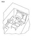
- FIG. 6is a perspective view of the exterior latch release mechanism of FIG. 2 .
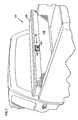
- FIG. 7is a perspective view of an alternative design of a motor vehicle box provided in the bed of a pickup truck according to the principles of the invention.
- FIG. 8is a perspective view of an alternative design of a motor vehicle box provided in the bed of a pickup truck according to the principles of the invention.
- a motor vehicle boxis shown at reference number 10 in the bed 12 of a pickup truck 14 .
- the motor vehicle box 10 shownis a truck bed box 16 because it is constructed to fit in a pickup truck bed 12 .
- the truck bed boxcan be constructed to fit directly behind the pickup truck cab 18 and between the pickup truck left bed sidewall 20 and the pickup truck bed right sidewall 22 .
- the truck bed box 16can be referred to as the box.
- the box 16is shown having a construction that extends between the left pickup truck sidewall 20 and the right pickup truck sidewall 22 , and over the left pickup truck sidewall top surface 24 and the right pickup truck sidewall top surface 26 .
- the box 16can be attached to the pickup truck 12 in a manner that is conventional for truck bed boxes.
- a gap 25can be provided between the box 16 and the pickup truck bed floor 28 .
- the box 16can be provided in a different location in the pickup truck bed 12 .
- the box 16can be provided along the left pickup truck sidewall 20 or the right pickup truck sidewall 22 .
- the box 16can have a different configuration than that shown in FIG. 1 .
- the box 16is fastened in place in the pickup truck bed 12 so that it does not move around during operation of the pickup truck.
- the box 16can be provided as an accessory that can be attached to the pickup truck bed 12 and later detached.
- the structure and operation of the box 16can be seen in reference to FIGS. 1-6 .
- the box 16includes a plurality of sidewalls 30 .
- the box 16includes a rear sidewall 32 , a left sidewall 34 , a right sidewall 36 , and a front sidewall (not shown) facing the pickup truck cab 18 .
- the boxincludes a bottom wall 38 and a lid 40 .
- the lid 40can be hingedly attached to one of the sidewalls.
- the walls and the lid of the box 16can be identical to the walls and lid of prior art boxes that are available from Lund Industries, Incorporated; Delta Consolidated, Incorporated; DeeZee, Inc.; and United Welding Supply.
- a common material that is available for manufacturing boxescan be referred to as diamond plate aluminum. This type of material can be used to manufacture the walls, bottom and lid of the box according to the invention.
- the lid 40can be manufactured according to U.S. application Ser. No. 10/210,784 that was filed with United States Patent and Trademark Office on Jul. 31, 2002. The entire disclosure of U.S. application Ser. No. 10/210,784 is incorporated herein by reference.
- the box 16includes a latch mechanism 50 that provides for latching the lid 40 in a closed position 42 and, when triggered, for releasing the lid 40 .
- the latch mechanism 50is shown latching the lid 40 to the rear sidewall 32 .
- a pin 49is provided extending from the lid 40 and engaging the latch mechanism 50 .
- the latch mechanism 50can be provided so that it latches the lid 40 to any of the sidewalls 30 .
- the latch mechanism 50includes a housing 51 , a latch member 52 and a latch release member 54 .
- the latch member 52can be spring-loaded and engages the pin 49 when the lid 40 is provided in the closed position 42 . In general, the latch member 52 engages the pin 49 , provided in the lid 40 , and the latch release member 54 causes the latch member 52 to disengage the pin 49 when the latch release member 54 is triggered.
- the latch release member 54can be triggered or activated by an exterior latch release mechanism 56 and/or an interior latch release mechanism 58 . It is expected that the exterior latch release mechanism 56 will be the mechanism most commonly used when opening the box 16 .
- the interior latch release mechanism 58is provided in the event that a person, such as a small child, finds himself or herself inside the box 16 with the lid 40 provided in the closed position 42 . The person inside the box 16 will be able to trigger the interior latch release mechanism 58 in order to get out of the box 16 .
- the exterior latch release mechanism 56can be triggered by depressing either or both of the buttons 60 and 62 . As shown in FIGS. 2 and 6 , depressing the button 62 moves the cam 70 causing the extension rod 72 to move in the direction of the arrow 74 .
- the button 62can include an extension or offset arm 63 that engages the first end 71 of the cam 70 . By anchoring the cam 70 at the rotation location 73 , the cam second end 75 can be provided to move through a desired degree of rotation.
- depressing the button 60causes the cam 64 to move the extension rod 66 in the direction of the arrow 68 .
- the extension rod 66 and the extension rod 72attached to the latch arm 80 at the first attachment location 82 and the second attachment location 84 , respectively.
- the latch arm 80rotates between the first latch position 86 and a second latch position provided when the latch arm 80 moves according to the arrows in FIG. 3 .
- the lid 40is capable of being latched in the closed position 42 .
- the lid 40can be opened. Moving the latch arm 80 to the second latch position causes the latch release member 54 to disengage the latch member 52 from the pin 49 .
- the interior latch release mechanism 58includes a lever arm 90 , a line 92 extending from the lever arm 90 , and a handle 94 attached to the line 92 .
- a personcan simply pull the handle 94 to cause the lever arm 90 to move between the first lever arm position 96 and the second lever on position provided when the lever arm 90 moves downward as shown by the arrow in FIG. 3 .
- the limit of movement of the lever arm 90can be determined by the size of the gap 99 shown in FIG. 5 .
- the first lever arm position 96allows the lid 40 to be latched in place in the closed position 42 .
- the second lever arm positionallows the lid 40 to be released so that the box 16 can be opened.
- the movement of the lever arm 90 to the second lever positioncauses the latch release member 54 to disengage the latch member 52 from the pin 49 .
- the handle 94can be provided from a material that glows in the dark. That is, the material used to form the handle 94 can be a material that gives off a sufficient amount of light when the lid 40 is attached to the rear sidewall 32 so that a person trapped within the box 16 will see the handle 94 and reach out to grab the handle and pull on it.
- the latch mechanism 50can be attached to the rear sidewall 32 by the bracket assembly 100 .
- the bracket 102can be provided to help attach the latch mechanism 50 to the bracket assembly 100 .
- the exterior latch release mechanism 56can be used in combination with a locking mechanism 110 .
- the locking mechanism 110can be locked and unlocked using a key that engages a keyhole 112 .
- the locking mechanism 110can be activated using an electronic control such as an electronic key fob.
- FIG. 7shows an alternative design of a box 120 according to the principles of the invention.
- the box 120includes a latch mechanism 122 having a lever 124 that, when lifted, releases the cover 126 from the box body 128 .
- the latch mechanism 122can include a keyhole 130 for locking and unlocking the box 120 .
- the box 120can be locked and unlocked using an electronic control such as an electronic key fob.
- FIG. 8shows an alternative embodiment of a box 140 according to the principles of the invention.
- the box 140includes a latch mechanism 142 that is provided as a rotating knob 144 .
- the rotating knobcan be locked and unlocked via the keyhole 146 .
- the box 140can be locked and unlocked using an electronic control such as an electronic key fob.
Landscapes
- Engineering & Computer Science (AREA)
- Mechanical Engineering (AREA)
- Health & Medical Sciences (AREA)
- Public Health (AREA)
- Transportation (AREA)
- Vehicle Step Arrangements And Article Storage (AREA)
- Closures For Containers (AREA)
Abstract
Description
Claims (8)
Priority Applications (3)
| Application Number | Priority Date | Filing Date | Title |
|---|---|---|---|
| US10/284,038US6959846B2 (en) | 2002-10-29 | 2002-10-29 | Motor vehicle box and pickup truck |
| MXPA03009822AMXPA03009822A (en) | 2002-10-29 | 2003-10-24 | Motor vehicle box and pickup truck. |
| CA002446482ACA2446482A1 (en) | 2002-10-29 | 2003-10-27 | Motor vehicle box and pickup truck |
Applications Claiming Priority (1)
| Application Number | Priority Date | Filing Date | Title |
|---|---|---|---|
| US10/284,038US6959846B2 (en) | 2002-10-29 | 2002-10-29 | Motor vehicle box and pickup truck |
Publications (2)
| Publication Number | Publication Date |
|---|---|
| US20040079777A1 US20040079777A1 (en) | 2004-04-29 |
| US6959846B2true US6959846B2 (en) | 2005-11-01 |
Family
ID=32107580
Family Applications (1)
| Application Number | Title | Priority Date | Filing Date |
|---|---|---|---|
| US10/284,038Expired - Fee RelatedUS6959846B2 (en) | 2002-10-29 | 2002-10-29 | Motor vehicle box and pickup truck |
Country Status (3)
| Country | Link |
|---|---|
| US (1) | US6959846B2 (en) |
| CA (1) | CA2446482A1 (en) |
| MX (1) | MXPA03009822A (en) |
Cited By (13)
| Publication number | Priority date | Publication date | Assignee | Title |
|---|---|---|---|---|
| US20050099021A1 (en)* | 2003-08-28 | 2005-05-12 | Mitsubishi Jidosha Kogyo Kabushiki Kaisha | Holding structure for trunk lid opening lever |
| US20070200362A1 (en)* | 2006-02-13 | 2007-08-30 | Paul Bacco | Releasable trailer door lock |
| US20070210600A1 (en)* | 2006-03-09 | 2007-09-13 | Young John S | Keyless entry pickup truck toolbox |
| US20090217714A1 (en)* | 2008-02-12 | 2009-09-03 | Scelzi Enterprises, Inc. | Rotary electronic utility box locking system |
| USD643234S1 (en) | 2009-02-05 | 2011-08-16 | Waterloo Industries, Inc. | Tool chest |
| USD645282S1 (en) | 2008-12-29 | 2011-09-20 | Waterloo Industries, Inc. | Tool chest |
| US20120104012A1 (en)* | 2010-11-01 | 2012-05-03 | Charles Henry Cowie | Container with Locking Mechanism |
| US20120267404A1 (en)* | 2011-04-19 | 2012-10-25 | Paul Rottinghaus | Modular Vehicle-Mounted Storage System |
| US20150047397A1 (en)* | 2013-08-15 | 2015-02-19 | John S. Lackey | Truck box with keyless entry system |
| US10316555B2 (en)* | 2015-09-18 | 2019-06-11 | Rom Acquisition Corporation | Truck roll-up door internal lock release |
| US11078683B2 (en)* | 2018-01-29 | 2021-08-03 | Werner Co. | Lockable latch handle assembly |
| US11085206B2 (en)* | 2018-01-29 | 2021-08-10 | Werner Co. | Lockable latch handle assembly |
| US11203302B2 (en)* | 2018-06-13 | 2021-12-21 | Thule Sweden Ab | Vehicle carrier box |
Families Citing this family (4)
| Publication number | Priority date | Publication date | Assignee | Title |
|---|---|---|---|---|
| GB0327231D0 (en)* | 2003-11-22 | 2003-12-24 | Cnh Uk Ltd | Utility box for an agricultural vehicle |
| US20100320245A1 (en)* | 2009-06-23 | 2010-12-23 | The Stanley Works Israel Ltd. | Truck bed mountable storage system |
| US9156412B1 (en)* | 2014-06-06 | 2015-10-13 | UETT Associates, Trustee for Upwardly Extensible Truck Toolbox CRT Trust | Upwardly extensible truck toolbox |
| US10081971B2 (en)* | 2017-02-17 | 2018-09-25 | Daws Manufacturing Company, Inc. | Latch assembly for NEMA enclosures |
Citations (13)
| Publication number | Priority date | Publication date | Assignee | Title |
|---|---|---|---|---|
| US3586360A (en)* | 1969-06-27 | 1971-06-22 | Langenau Mfg Co The | Latch mechanism |
| US3640423A (en)* | 1970-07-01 | 1972-02-08 | Parker Ind Inc | Toolbox for pickup truck |
| US4080812A (en)* | 1975-06-03 | 1978-03-28 | Helen H. Knott | Automobile trunk lock |
| US5308126A (en)* | 1990-09-17 | 1994-05-03 | Knaack Manufacturing Company | Push-button lock system |
| US5445326A (en)* | 1993-12-21 | 1995-08-29 | Ferro; Joseph | Emergency trunk interior release latch |
| US5601206A (en)* | 1995-06-06 | 1997-02-11 | Rubbermaid Specialty Products, Inc. | Truck box |
| US5875948A (en)* | 1996-08-30 | 1999-03-02 | Randall C. Hansen | Truck box with end-mounted paddle handle and latching mechanism therefor |
| US5924616A (en)* | 1997-04-11 | 1999-07-20 | Shives; Mark E. | Storage box for storing cargo in a pick-up truck |
| US6135514A (en)* | 1999-09-13 | 2000-10-24 | Delphi Technologies, Inc. | Automotive vehicle storage compartment release mechanism |
| US6394511B1 (en)* | 1999-12-01 | 2002-05-28 | Ford Global Technologies, Inc. | Automotive vehicle decklid latch system |
| US6454320B1 (en)* | 1999-10-28 | 2002-09-24 | The Eastern Company | Push button operators for latches and locks and locking systems employing lockable push button operators |
| US6581989B2 (en)* | 2001-05-08 | 2003-06-24 | Frank Markisello | Safety release device for closure latches, release latch and storage compartment utilizing safety release device, and method of installing safety release device |
| US6742818B2 (en)* | 2000-06-30 | 2004-06-01 | Kabushiki Kaisha Tokai Rika Denki Seisakusho | Box lock with safety device |
- 2002
- 2002-10-29USUS10/284,038patent/US6959846B2/ennot_activeExpired - Fee Related
- 2003
- 2003-10-24MXMXPA03009822Apatent/MXPA03009822A/enactiveIP Right Grant
- 2003-10-27CACA002446482Apatent/CA2446482A1/ennot_activeAbandoned
Patent Citations (13)
| Publication number | Priority date | Publication date | Assignee | Title |
|---|---|---|---|---|
| US3586360A (en)* | 1969-06-27 | 1971-06-22 | Langenau Mfg Co The | Latch mechanism |
| US3640423A (en)* | 1970-07-01 | 1972-02-08 | Parker Ind Inc | Toolbox for pickup truck |
| US4080812A (en)* | 1975-06-03 | 1978-03-28 | Helen H. Knott | Automobile trunk lock |
| US5308126A (en)* | 1990-09-17 | 1994-05-03 | Knaack Manufacturing Company | Push-button lock system |
| US5445326A (en)* | 1993-12-21 | 1995-08-29 | Ferro; Joseph | Emergency trunk interior release latch |
| US5601206A (en)* | 1995-06-06 | 1997-02-11 | Rubbermaid Specialty Products, Inc. | Truck box |
| US5875948A (en)* | 1996-08-30 | 1999-03-02 | Randall C. Hansen | Truck box with end-mounted paddle handle and latching mechanism therefor |
| US5924616A (en)* | 1997-04-11 | 1999-07-20 | Shives; Mark E. | Storage box for storing cargo in a pick-up truck |
| US6135514A (en)* | 1999-09-13 | 2000-10-24 | Delphi Technologies, Inc. | Automotive vehicle storage compartment release mechanism |
| US6454320B1 (en)* | 1999-10-28 | 2002-09-24 | The Eastern Company | Push button operators for latches and locks and locking systems employing lockable push button operators |
| US6394511B1 (en)* | 1999-12-01 | 2002-05-28 | Ford Global Technologies, Inc. | Automotive vehicle decklid latch system |
| US6742818B2 (en)* | 2000-06-30 | 2004-06-01 | Kabushiki Kaisha Tokai Rika Denki Seisakusho | Box lock with safety device |
| US6581989B2 (en)* | 2001-05-08 | 2003-06-24 | Frank Markisello | Safety release device for closure latches, release latch and storage compartment utilizing safety release device, and method of installing safety release device |
Non-Patent Citations (3)
| Title |
|---|
| "DeeZee: The Quality Truck Accessory People: 1993 Catalog", DeeZee, Inc., front cover, pp. 1-23, back cover (1993). |
| "Deflecta-Shield Aluminum Products", Lund International, front cover, pp. 1-13, back cover (2001-2002). |
| "Diamond Brite Tool Boxes by Challenger", Delta III, Inc., front cover, p. 1-2, back cover (Date Unknown). |
Cited By (17)
| Publication number | Priority date | Publication date | Assignee | Title |
|---|---|---|---|---|
| US20050099021A1 (en)* | 2003-08-28 | 2005-05-12 | Mitsubishi Jidosha Kogyo Kabushiki Kaisha | Holding structure for trunk lid opening lever |
| US20070200362A1 (en)* | 2006-02-13 | 2007-08-30 | Paul Bacco | Releasable trailer door lock |
| US7510224B2 (en)* | 2006-02-13 | 2009-03-31 | Southwest Mobile Storage, Inc. | Releasable trailer door lock |
| US7735884B2 (en) | 2006-02-13 | 2010-06-15 | Southwest Mobile Storage, Inc. | Releasable trailer door lock |
| US20070210600A1 (en)* | 2006-03-09 | 2007-09-13 | Young John S | Keyless entry pickup truck toolbox |
| US8869576B2 (en)* | 2008-02-12 | 2014-10-28 | Kevin Daniel O'Leary | Rotary electronic utility box locking system |
| US20090217714A1 (en)* | 2008-02-12 | 2009-09-03 | Scelzi Enterprises, Inc. | Rotary electronic utility box locking system |
| USD645282S1 (en) | 2008-12-29 | 2011-09-20 | Waterloo Industries, Inc. | Tool chest |
| USD643234S1 (en) | 2009-02-05 | 2011-08-16 | Waterloo Industries, Inc. | Tool chest |
| US20120104012A1 (en)* | 2010-11-01 | 2012-05-03 | Charles Henry Cowie | Container with Locking Mechanism |
| US20120267404A1 (en)* | 2011-04-19 | 2012-10-25 | Paul Rottinghaus | Modular Vehicle-Mounted Storage System |
| US20150047397A1 (en)* | 2013-08-15 | 2015-02-19 | John S. Lackey | Truck box with keyless entry system |
| US9151078B2 (en)* | 2013-08-15 | 2015-10-06 | Daws Manufacturing Co., Inc. | Truck box with keyless entry system |
| US10316555B2 (en)* | 2015-09-18 | 2019-06-11 | Rom Acquisition Corporation | Truck roll-up door internal lock release |
| US11078683B2 (en)* | 2018-01-29 | 2021-08-03 | Werner Co. | Lockable latch handle assembly |
| US11085206B2 (en)* | 2018-01-29 | 2021-08-10 | Werner Co. | Lockable latch handle assembly |
| US11203302B2 (en)* | 2018-06-13 | 2021-12-21 | Thule Sweden Ab | Vehicle carrier box |
Also Published As
| Publication number | Publication date |
|---|---|
| US20040079777A1 (en) | 2004-04-29 |
| MXPA03009822A (en) | 2005-04-19 |
| CA2446482A1 (en) | 2004-04-29 |
Similar Documents
| Publication | Publication Date | Title |
|---|---|---|
| US6959846B2 (en) | Motor vehicle box and pickup truck | |
| US8903605B2 (en) | System to remotely unlatch a pickup box tailgate | |
| US5927772A (en) | Ratcheting pawl latch | |
| US8532873B1 (en) | System to remotely unlatch a pickup box tailgate | |
| JP3854029B2 (en) | Door lock device for automobile | |
| JPH0223372B2 (en) | ||
| US5794992A (en) | Protected vehicle door latch device | |
| US7055881B2 (en) | Utility box for an agricultural vehicle | |
| KR102702476B1 (en) | glove box for vehicle | |
| JP2565196Y2 (en) | Lock device for glove box | |
| KR100610913B1 (en) | Remote controller of car slide door | |
| JP2575993Y2 (en) | Article storage device | |
| JP2883561B2 (en) | Door lock handle device | |
| JPH0712574Y2 (en) | Door lock handle device | |
| JP3923123B2 (en) | Anti-theft cancel structure for front-rear rear seat back | |
| JPH0333907Y2 (en) | ||
| JPH046340Y2 (en) | ||
| JP2004276939A (en) | Vehicle-mounted storage box | |
| JPH0721395Y2 (en) | Seat back lock device | |
| JPH059949Y2 (en) | ||
| JPH0345504Y2 (en) | ||
| JPH0320195Y2 (en) | ||
| KR200230976Y1 (en) | Rear seat folding lock | |
| WO2000050712A1 (en) | Console latch with living handle | |
| JPH0345503Y2 (en) |
Legal Events
| Date | Code | Title | Description |
|---|---|---|---|
| AS | Assignment | Owner name:LUND INDUSTRIES, INC., MINNESOTA Free format text:ASSIGNMENT OF ASSIGNORS INTEREST;ASSIGNORS:SCHOMAKER, JEROME A.;METTLER, DEAN;WEIDERMAN, JAMES;AND OTHERS;REEL/FRAME:013685/0961;SIGNING DATES FROM 20021218 TO 20030109 | |
| AS | Assignment | Owner name:LUND INTERNATIONAL, INC., MINNESOTA Free format text:ASSIGNMENT OF ASSIGNORS INTEREST;ASSIGNOR:LUND INDUSTRIES, INC.;REEL/FRAME:013804/0407 Effective date:20030227 | |
| AS | Assignment | Owner name:GENERAL ELECTRIC CAPITAL CORPORATION, NEW YORK Free format text:SECURITY AGREEMENT;ASSIGNOR:LUND INTERNATIONAL, INC.;REEL/FRAME:013845/0588 Effective date:20030228 | |
| AS | Assignment | Owner name:LUND, INC., GEORGIA Free format text:ASSIGNMENT OF ASSIGNORS INTEREST;ASSIGNORS:LUND INTERNATIONAL HOLDINGS, INC.;LUND INTERNATIONAL, INC.;REEL/FRAME:020317/0743 Effective date:20071129 | |
| AS | Assignment | Owner name:GENERAL ELECTRIC CAPITAL CORPORATION, AS ADMINISTR Free format text:SECURITY AGREEMENT;ASSIGNOR:LUND, INC.;REEL/FRAME:020403/0930 Effective date:20071130 | |
| REMI | Maintenance fee reminder mailed | ||
| LAPS | Lapse for failure to pay maintenance fees | ||
| STCH | Information on status: patent discontinuation | Free format text:PATENT EXPIRED DUE TO NONPAYMENT OF MAINTENANCE FEES UNDER 37 CFR 1.362 | |
| FP | Lapsed due to failure to pay maintenance fee | Effective date:20091101 | |
| AS | Assignment | Owner name:BELMOR, INC., GEORGIA Free format text:RELEASE BY SECURED PARTY;ASSIGNOR:GENERAL ELECTRIC CAPITAL CORPORATION;REEL/FRAME:026205/0422 Effective date:20110427 Owner name:LUND, INC., GEORGIA Free format text:RELEASE BY SECURED PARTY;ASSIGNOR:GENERAL ELECTRIC CAPITAL CORPORATION;REEL/FRAME:026205/0422 Effective date:20110427 Owner name:LUND INTERNATINAL, INC., GEORGIA Free format text:RELEASE BY SECURED PARTY;ASSIGNOR:GENERAL ELECTRIC CAPITAL CORPORATION;REEL/FRAME:026205/0422 Effective date:20110427 |