US6959748B2 - Apparatus for covering an opening in a building - Google Patents
Apparatus for covering an opening in a buildingDownload PDFInfo
- Publication number
- US6959748B2 US6959748B2US10/313,057US31305702AUS6959748B2US 6959748 B2US6959748 B2US 6959748B2US 31305702 AUS31305702 AUS 31305702AUS 6959748 B2US6959748 B2US 6959748B2
- Authority
- US
- United States
- Prior art keywords
- curtain assembly
- opening
- frames
- spring
- sealing surface
- Prior art date
- Legal status (The legal status is an assumption and is not a legal conclusion. Google has not performed a legal analysis and makes no representation as to the accuracy of the status listed.)
- Expired - Lifetime
Links
- 238000007789sealingMethods0.000claimsabstractdescription26
- 239000004744fabricSubstances0.000claimsdescription24
- 239000000463materialSubstances0.000claimsdescription10
- XLYOFNOQVPJJNP-UHFFFAOYSA-NwaterSubstancesOXLYOFNOQVPJJNP-UHFFFAOYSA-N0.000claims2
- 230000001012protectorEffects0.000abstract2
- 230000000694effectsEffects0.000description3
- 238000007664blowingMethods0.000description2
- 238000009434installationMethods0.000description2
- 230000003014reinforcing effectEffects0.000description2
- JOYRKODLDBILNP-UHFFFAOYSA-NEthyl urethaneChemical compoundCCOC(N)=OJOYRKODLDBILNP-UHFFFAOYSA-N0.000description1
- 239000004677NylonSubstances0.000description1
- 238000004026adhesive bondingMethods0.000description1
- 230000000712assemblyEffects0.000description1
- 238000000429assemblyMethods0.000description1
- 230000003247decreasing effectEffects0.000description1
- 230000001419dependent effectEffects0.000description1
- 238000000034methodMethods0.000description1
- 238000012986modificationMethods0.000description1
- 230000004048modificationEffects0.000description1
- 229920001778nylonPolymers0.000description1
- 230000002093peripheral effectEffects0.000description1
- 229920000728polyesterPolymers0.000description1
- 238000009958sewingMethods0.000description1
- 238000003466weldingMethods0.000description1
Images


Classifications
- E—FIXED CONSTRUCTIONS
- E06—DOORS, WINDOWS, SHUTTERS, OR ROLLER BLINDS IN GENERAL; LADDERS
- E06B—FIXED OR MOVABLE CLOSURES FOR OPENINGS IN BUILDINGS, VEHICLES, FENCES OR LIKE ENCLOSURES IN GENERAL, e.g. DOORS, WINDOWS, BLINDS, GATES
- E06B9/00—Screening or protective devices for wall or similar openings, with or without operating or securing mechanisms; Closures of similar construction
- E06B9/56—Operating, guiding or securing devices or arrangements for roll-type closures; Spring drums; Tape drums; Counterweighting arrangements therefor
- E06B9/68—Operating devices or mechanisms, e.g. with electric drive
- E—FIXED CONSTRUCTIONS
- E06—DOORS, WINDOWS, SHUTTERS, OR ROLLER BLINDS IN GENERAL; LADDERS
- E06B—FIXED OR MOVABLE CLOSURES FOR OPENINGS IN BUILDINGS, VEHICLES, FENCES OR LIKE ENCLOSURES IN GENERAL, e.g. DOORS, WINDOWS, BLINDS, GATES
- E06B9/00—Screening or protective devices for wall or similar openings, with or without operating or securing mechanisms; Closures of similar construction
- E06B9/24—Screens or other constructions affording protection against light, especially against sunshine; Similar screens for privacy or appearance; Slat blinds
- E06B9/40—Roller blinds
- E06B9/42—Parts or details of roller blinds, e.g. suspension devices, blind boxes
- E—FIXED CONSTRUCTIONS
- E06—DOORS, WINDOWS, SHUTTERS, OR ROLLER BLINDS IN GENERAL; LADDERS
- E06B—FIXED OR MOVABLE CLOSURES FOR OPENINGS IN BUILDINGS, VEHICLES, FENCES OR LIKE ENCLOSURES IN GENERAL, e.g. DOORS, WINDOWS, BLINDS, GATES
- E06B9/00—Screening or protective devices for wall or similar openings, with or without operating or securing mechanisms; Closures of similar construction
- E06B9/56—Operating, guiding or securing devices or arrangements for roll-type closures; Spring drums; Tape drums; Counterweighting arrangements therefor
- E06B9/58—Guiding devices
- E06B9/581—Means to prevent or induce disengagement of shutter from side rails
- E—FIXED CONSTRUCTIONS
- E06—DOORS, WINDOWS, SHUTTERS, OR ROLLER BLINDS IN GENERAL; LADDERS
- E06B—FIXED OR MOVABLE CLOSURES FOR OPENINGS IN BUILDINGS, VEHICLES, FENCES OR LIKE ENCLOSURES IN GENERAL, e.g. DOORS, WINDOWS, BLINDS, GATES
- E06B9/00—Screening or protective devices for wall or similar openings, with or without operating or securing mechanisms; Closures of similar construction
- E06B9/56—Operating, guiding or securing devices or arrangements for roll-type closures; Spring drums; Tape drums; Counterweighting arrangements therefor
- E06B9/62—Counterweighting arrangements
- E—FIXED CONSTRUCTIONS
- E06—DOORS, WINDOWS, SHUTTERS, OR ROLLER BLINDS IN GENERAL; LADDERS
- E06B—FIXED OR MOVABLE CLOSURES FOR OPENINGS IN BUILDINGS, VEHICLES, FENCES OR LIKE ENCLOSURES IN GENERAL, e.g. DOORS, WINDOWS, BLINDS, GATES
- E06B9/00—Screening or protective devices for wall or similar openings, with or without operating or securing mechanisms; Closures of similar construction
- E06B9/56—Operating, guiding or securing devices or arrangements for roll-type closures; Spring drums; Tape drums; Counterweighting arrangements therefor
- E06B9/80—Safety measures against dropping or unauthorised opening; Braking or immobilising devices; Devices for limiting unrolling
- E06B9/82—Safety measures against dropping or unauthorised opening; Braking or immobilising devices; Devices for limiting unrolling automatic
- E06B9/90—Safety measures against dropping or unauthorised opening; Braking or immobilising devices; Devices for limiting unrolling automatic for immobilising the closure member in various chosen positions
Definitions
- This inventionrelates to a device for covering an opening in a structure, such as a window or the like, to protect the structure's envelope from being breached by impact from debris or high velocity wind loads. More particularly, this invention relates to such a device which can seal and protect the opening against the pressure of the wind.
- Extreme weather-created phenomenonsuch as hurricanes, typhoons, tornadoes, or the like can often cause damage to building structures.
- Such storm-related damagefrequently occurs when high winds and/or debris carried thereby invades the structure through its weakest points, its openings, such as windows or doors. Once invaded, the structure is vulnerable to further damage to the interior thereof, and thus, particularly in geographic areas susceptible to frequent violent weather conditions, it is important to protect the weakest portions of a structure, at least the windows and the doors, with some type of covering.
- a device for covering an opening in a building made in accordance with one aspect of the present inventionincludes opposed frames with a curtain assembly being manually movable along the frames.
- a deviceis carried by the curtain assembly to selectively be received by at least one of the frames to guide the curtain assembly along the frames.
- a device for covering an opening in a buildingincludes a tube having one end of a curtain assembly attached thereto.
- the curtain assemblyis adapted to be coiled on the tube when it is not covering the opening and to be uncoiled from the tube to cover the opening.
- a springis provided to bias the curtain assembly toward the coiled position, and a tension adjusting system is provided which adjusts the tension of the spring without having to disassemble the apparatus.
- a device for covering an opening in a buildingincludes an upper member, a lower member, and opposed side members which extend between the edges of the upper and lower members. Together, the upper, lower and side members form the periphery of the device.
- a curtain assemblyis adapted to extend between the upper and lower members and between the side members to cover the space therebetween.
- the upper, lower and side memberseach have a sealing surface so that when the curtain assembly is exposed to a force, the periphery of the curtain assembly can engage each sealing surface.
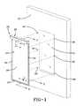
- FIG. 1is a perspective view of a device made in accordance with the concept of the present invention and showing the manner in which it may be received over a window of a structure.
- FIG. 2is an exploded perspective view of the device of FIG. 1 .
- FIG. 3is an enlarged view of a locking mechanism of the device circled in FIG. 2 and labeled 3 , showing the mechanism in the locked position.
- FIG. 3Ais a view similar to FIG. 3 but showing the locking mechanism in an unlocked condition.
- FIG. 4is an exploded view of the locking mechanism shown in FIG. 3 .
- FIG. 5Ais a sectional view taken substantially along line 5 — 5 of FIG. 1 showing the flexible material of the device under pressure from wind directed there against.
- FIG. 5Bis a sectional view like FIG. 5A but showing the flexible material in a vacuum condition.
- FIG. 6Ais a sectional view taken substantially along line 6 — 6 of FIG. 2 showing the mechanism of FIG. 3 in an unlocked condition and showing flexible material of the device under pressure from wind directed there against.
- FIG. 6Bis a sectional view like FIG. 6A showing the mechanism of FIG. 3 in a locked condition.
- FIG. 6Cis a sectional view like FIG. 6B but showing the flexible material in a vacuum condition.
- FIG. 7is a sectional view taken substantially along line 7 — 7 of FIG. 1 showing the flexible material in a retracted condition.
- FIG. 8is a sectional view taken substantially along line 8 — 8 of FIG. 2 .
- FIG. 9is an enlarged exploded perspective view of the portion of the device circled in FIG. 2 and labeled 9 .
- FIG. 10is a partially exploded perspective view showing the majority of the components of FIG. 9 assembled.
- a storm protection device made in accordance with the present inventionis indicated generally by the numeral 20 and is shown in FIG. 1 as being attachable over a window 21 or other opening of a structure 22 .
- Storm protection device 20includes opposed side frames 23 , 24 , a bottom sill 25 extending between the lower end of frames 23 and 24 , a header or curtain storage area 26 extending between the upper end of frames 23 and 24 , and a curtain assembly generally indicated by the numeral 27 .
- Device 20can be attached to structure 22 by means of conventional fasteners 28 received through frames 23 , 24 .
- Curtain assembly 27includes a sheet of fabric 29 having a strip of material 30 attached to each vertical edge thereof.
- Strips 30can be separate pieces of material attached to fabric sheet 29 such as by sewing, gluing, or welding, or alternatively, the edges of sheet 29 could be folded over and sewn to form the thickened edges otherwise created by strips 30 on sheet 29 .
- the fabric of sheet 29can be of any sturdy, preferably lightweight, material which is weather resistant and which can withstand the forces generated by high winds or flying debris. For example, a vinyl- or urethane-coated nylon or polyester fabric would be suitable for sheet 29 .
- curtain assembly 27also includes a bar 31 attached to one end of fabric sheet 29 .
- the other end of fabric sheet 29is carried by a tensioning assembly, best shown in FIG. 9 and generally indicated by the numeral 32 .
- Tension assembly 32is part of header 26 , and, as will hereinafter be described in detail, when not in use, fabric sheet 29 is coiled within header 26 , as shown in FIG. 7 .
- header 26is shown at the top of storm protection device 20 with curtain assembly 27 being movable vertically therefrom, it will become evident that header 26 could be formed at the side of device 20 and with the curtain assembly then being movable horizontally across device 20 without departing from the spirit of this invention.
- Header 26includes a housing to store curtain assembly 27 which can be conveniently formed from two housing portions generally indicated by the numerals 33 and 34 . As shown in FIG. 7 , when assembled in a manner to be hereinafter described, housing portion 33 forms the top surface 35 and one side surface 36 of the header 26 , and housing portion 34 forms the bottom surface 37 and an opposed side surface 38 of header 26 .
- top surface 35 and side surface 36 of housing portion 33are formed with a lug 39 to receive a fastener 40 (FIG. 9 ).
- the opposite end of top surface 35is formed with a lug 41 to receive a fastener 42 (FIG. 9 ), and, similarly, the opposite end of side surface 36 is formed with a lug 43 to receive a fastener 44 (FIG. 10 ).
- bottom surface 37 and side surface 38 of housing portion 34is likewise formed with a lug 45 to receive a fastener 46 (FIG. 9 ), the opposite end of bottom surface 37 being formed with a lug 47 to receive a fastener (not shown).
- the opposite end of side surface 38is formed with a tongue 48 which fits within a groove 49 formed in lug 41 .
- header 26When header 26 is assembled, lug 43 of side surface 36 is spaced from lug 47 of bottom surface 37 to provide a space or opening for the fabric sheet 29 to pass therebetween. Also, as will hereinafter be described in more detail, a sealing surface 50 is formed on lug 47 SO that when fabric sheet 29 is receiving wind pressure, as coming from the left in FIG. 7 , sheet 29 will deflect and engage surface 50 to seal the top periphery of curtain assembly 27 .
- housing portions 33 and 34are maintained assembled to form header 26 by means of end caps 51 which can be slid into each end of housing portions 33 and 34 and attached thereto by virtue of apertures 52 near the four corners thereof which are aligned with aperture lugs 39 , 41 , 43 and 45 to receive fasteners 40 , 42 , 44 and 46 therethrough, respectively.
- a supply of the fabric sheet 29is maintained within header 26 and is coiled on a counterbalance tube 53 which is part of tensioning assembly 32 and which, as was previously described, is attached to one end of sheet 29 .
- tube 53 and the tensioning assembly 32allow the fabric sheet 29 to be coiled thereon or uncoiled therefrom.
- a counterbalance spring 54has one end attached to turn with tube 53 , and its other end is attached to a driver 55 .
- the outer end of driver 55extends through an opening (not shown) in end cap 51 and receives a splined extension of a nut 56 which is engaged by the inner configuration of an aperture 57 formed in a gear plate 58 .
- the periphery of plate 58is provided with a plurality of radially projecting teeth 59 .
- Teeth 59interrelate with a pawl assembly, generally indicated by the numeral 60 , to incrementally maintain the position of the end of spring 54 by way of driver 55 .
- gear plate 58is shown as having ten teeth 59 , the number thereof may be increased or decreased depending on the amount of the desired tensioning increment. That increment, in terms of one revolution of gear plate 58 , is basically inversely proportioned to the number of teeth 59 . Thus, in the embodiment shown with ten teeth, there is a tensioning increment of 1/10 of a revolution.
- Pawl assembly 60interacts with teeth 59 to hold plate 58 against the force of spring 54 .
- Pawl assembly 60includes a pivot portion 61 having an aperture 62 therethrough which is received on a hub 63 formed on end cap 51 .
- a tooth engaging arm 64extends outwardly from pivot portion 61 toward gear plate 58 .
- Arm 64is a wedge-like member having a first flat surface 65 that is engaged by the leading surface of a tooth 59 and a second surface 66 that engages the trailing side of a tooth 59 to hold gear plate 58 against rotation.
- Pawl assembly 60also preferably includes a spring 67 which is received around hub 63 and, as would be evident to one skilled in the art, is positioned so as to exert a force to urge arm 64 toward engagement with gear plate 58 .
- the components of the tensioning assembly 32are maintained housed within one end cap 51 by an end plate 68 .
- Plate 68is provided with three peripheral apertures 69 which are alignable with fastener receiving lugs 70 formed on frame 51 .
- a generally central aperture 71 in plate 68is positioned so as to expose nut 56 .
- at least one fastener 72may be employed to extend through one of the apertures 69 and into one of the lugs 70 to hold plate 68 onto frame 51 .
- a cover plate 73is provided to completely close off each end of header 26 , and it is preferably provided with two apertures 74 which, on the end of header 26 having tensioning assembly 32 , which can be aligned with two of the apertures 69 of plate 68 so that fasteners 75 may be received through apertures 69 and 68 and into lugs 70 .
- the tension on spring 54may thus be readily and easily adjusted by the structure just described. To that end, all that one need do is remove cover plate 73 so that adjusting nut 56 is exposed through aperture 71 of plate 68 . Then nut 56 can be turned clockwise to overcome the force of pawl 60 and incrementally add tension to spring 54 . If it is desired to remove tension from spring 54 , nut 56 can be rotated slightly in the tensioning direction until pawl 60 can be freed from engagement of gear plate 58 which is accomplished by manually rotating pawl 60 to overcome the bias of spring 67 . With arm 64 thus out of engagement with teeth 59 , rotation of nut 56 in the non-tensioning direction (counterclockwise) will remove tension from spring 54 . Thus, the tensioning of spring 54 is readily adjustable by removing only cover plate 73 and not otherwise having to disassemble the device.
- Side frame 24includes a front or outer surface 80 spaced from a rear or inner surface 81 by an outer end wall 82 .
- inner surface 81is positioned against structure 22 .
- An inner end wall 83is formed at the inner end of surface 81 but does not extend all the way to front surface 80 . Rather, it terminates short of an intermediate wall 84 thereby creating a space to receive the edge of curtain assembly 27 .
- Intermediate wall 84is formed generally parallel to front and rear surfaces 80 , 81 and is supported by a stub wall 85 extending between front surface 80 and wall 84 , and by a support wall 86 extending between rear surface 81 and wall 84 .
- a reinforcing wall 87is positioned parallel to wall 84 , and surface 80 and surface 81 , and extends between inner end wall 83 and support wall 86 .
- a sealing surface 89is formed on the end of wall 83 .
- the sheet 29is forced against surface 89 , thereby effecting a seal along each side of fabric sheet 29 , in the same manner that surface 50 effects a top seal.
- the vacuum condition shown in FIG. 6Cmay occur with the thickened area 30 of sheet 29 engaging wall 87 , as the wind passes over the top of structure 22 .
- Side frames 23 and 24also include opposed nubs 90 extending from walls 82 and 86 toward each other to form, with walls 81 , 82 and 86 , a socket 91 .
- Socket 91is configured to enable side frames 23 and 24 to be attached to sill 25 and header 26 . That is, a post 92 formed on end cap 51 of header 26 is snugly received in the upper end of socket 91 , and it can be held in place, if necessary, by fasteners (not shown).
- the lower end of socket 91is adapted to snugly receive one post 93 of a corner key 94 (FIG. 2 ). Like post 92 , if necessary, post 93 can be more permanently held in place in frames 23 , 24 by fasteners (not shown).
- Corner key 94also includes a second post 95 positioned normal to post 93 . Posts 95 of each corner key 94 are adapted to be received in sill 25 , as now to be described with reference to FIGS. 5A and 5B .
- Sill 25is formed with an inner surface 96 , which will be positioned adjacent to the structure 22 when device 20 is installed, and a stepped outer surface consisting of a lower portion 97 and an upper portion 98 .
- a step 99is formed between portions 97 and 98 which serves as a ledge for bar 31 which, as previously described, is attached to the bottom of fabric sheet 29 .
- a top wall 100extends between upper portion 98 of the outer surface and inner surface 96
- a bottom wall 101extends between lower portion 97 of the outer surface 80 and inner surface 96 .
- a reinforcing wall 102extends between the bottom of wall portion 98 and inner surface 96 .
- Opposed nubs 103extend toward each other from step 99 and lower wall 101 to form with inner surface 96 , wall portion 97 and lower wall 101 , a socket 104 .
- Socket 104is configured to snugly receive, at each end, posts 95 of corner keys 94 to attach sill 25 between frames 23 and 24 . If necessary, fasteners (not shown) may be utilized to make the connection more permanent.
- a sealing surface 105is formed at the junction of top wall 100 and portion 98 of the stepped outer surface.
- the edges thereofbe guided in a track-like fashion by side frames 23 and 24 .
- a slot 106is formed in side frames 23 and 24 located between the inner end of intermediate wall 84 and the inner end of front surface 80 .
- the device which guides the fabric sheetcould be a member (not shown) which is inserted into the hollow portion 107 of bar 31 (FIG. 8 ), that member having an outwardly extending flange capable of riding in slots 106 of side frames 23 and 24 .
- the guiding devicecould also serve a locking function to hold curtain assembly 27 in the fully closed position, as shown in FIG. 1 , or in any intermediate position, as shown in FIG. 2 , should that be desired, in instances, for example, when the owner of the structure 22 is using curtain assembly 27 as a partial shade for window 21 .
- Assembly 110includes a housing 111 which is carried by bar 31 near at least one end thereof, but preferably at both ends thereof so as to be interrelated to both frames 23 and 24 .
- Each housing 111has an opening therein through which a flange 112 of a plunger 113 extends.
- Plunger 113has a socket 114 formed at its other end to receive one end of coil spring 115 .
- the other end of spring 115is piloted over a lug 116 formed in housing 111 .
- a button 117has a tab 118 which is received through a slot 119 in housing 111 to engage a recess 120 formed in plunger 113 .
- spring 115normally acts on plunger 113 so that flange 112 is in slot 106 of the side frame 23 and/or 24 adjacent to assembly 110 .
- Flange 112is tapered on both sides thereof, as at 121 , so as to be generally wedged in slot 106 as shown in FIG. 6 B. In this position, curtain assembly 27 is held in place relative to frames 23 and 24 at a height selected by the user.
- the taper 121also permits the pivoting of flange 112 in slot 106 under certain wind conditions as shown in FIG. 6 C.
- curtain assembly 27When it is desired to unlock curtain assembly 27 and move it to a new position, the user merely slides button 117 as shown in FIG. 3A to overcome the bias of spring 115 to retract the tapered portion of flange 112 from slot 106 so that, as shown in FIG. 6A , flange 112 is no longer locked in slot 106 but yet is still sufficiently within slot 106 to provide a guiding function when curtain assembly 27 is being manually extended out of or retracted into header 26 . Then, upon release of the button 117 of assemblies 110 , curtain assembly 27 will again be held at its intended position by flange 112 being extended by spring 115 .
Landscapes
- Engineering & Computer Science (AREA)
- Structural Engineering (AREA)
- Architecture (AREA)
- Civil Engineering (AREA)
- Operating, Guiding And Securing Of Roll- Type Closing Members (AREA)
- Curtains And Furnishings For Windows Or Doors (AREA)
Abstract
Description
This invention relates to a device for covering an opening in a structure, such as a window or the like, to protect the structure's envelope from being breached by impact from debris or high velocity wind loads. More particularly, this invention relates to such a device which can seal and protect the opening against the pressure of the wind.
Extreme weather-created phenomenon, such as hurricanes, typhoons, tornadoes, or the like can often cause damage to building structures. Such storm-related damage frequently occurs when high winds and/or debris carried thereby invades the structure through its weakest points, its openings, such as windows or doors. Once invaded, the structure is vulnerable to further damage to the interior thereof, and thus, particularly in geographic areas susceptible to frequent violent weather conditions, it is important to protect the weakest portions of a structure, at least the windows and the doors, with some type of covering.
Most traditionally, home or building owners, if alerted to an oncoming storm, cover these portions of their structures by nailing boards over them. However, this “boarding up” procedure is not only time consuming, when time is usually of the essence, but such can also disfigure the exterior of the structure upon the frequent installation and removal of the boards. Moreover, storing or maintaining an inventory of the boards can take up a great deal of space which would otherwise be usable for other purposes.
As a result, a number of temporarily installable or permanently installed devices have been developed in an attempt to protect these portions of a structure. Some of these devices are in the form of a shutter consisting of a plurality of hinge-connected slats. These shutters can be rolled up and away from the portion of the building being protected by a hand crank or motor. However, these types of devices are not only costly, but also they do not provide for an adequate seal irrespective of whether they are mounted on the windward or leeward side of the structure.
Other alternatives to these shutter-like devices are fabric-based systems. These systems, while less expensive than their counterparts, are often quite large, cumbersome, and difficult to install. Usually, they are attached to an overhang or an eave and must be positioned at a distance in excess of two feet, from the window or door to be protected. They must be specially designed for each such item to be covered, dependent on the nature of the item and its location relative to an overhang or an eave, and they are usually quite large, presenting installation and storage issues.
The need exists, therefore, for a system which will not be plagued by these problems of the prior art.
It is thus an object of the present invention to provide a device for covering an opening, such as a window or a door, of a building structure.
It is another object of the present invention to provide a device, as above, which is in the form of a curtain of a flexible material which may be manually operated to be positioned over the opening.
It is a further object of the present invention to provide a device, as above, in which the curtain may be wound up by a spring and stored at a position adjacent to the opening.
It is yet another object of the present invention to provide a device, as above, in which the tension on the spring may be adjusted without disassembling the device.
It is still a further object of the present invention to provide a device, as above, wherein the curtain may be held open at a plurality of positions.
It is an additional object of the present invention to provide a device, as above, which can protect and provide a full perimeter seal for the opening against the pressure of the wind.
These and other objects of the present invention, as well as the advantages thereof over existing prior art forms, which will become apparent from the description to follow, are accomplished by the improvements hereinafter described and claimed.
In general, a device for covering an opening in a building made in accordance with one aspect of the present invention includes opposed frames with a curtain assembly being manually movable along the frames. A device is carried by the curtain assembly to selectively be received by at least one of the frames to guide the curtain assembly along the frames.
In accordance with another aspect of the present invention, a device for covering an opening in a building includes a tube having one end of a curtain assembly attached thereto. The curtain assembly is adapted to be coiled on the tube when it is not covering the opening and to be uncoiled from the tube to cover the opening. A spring is provided to bias the curtain assembly toward the coiled position, and a tension adjusting system is provided which adjusts the tension of the spring without having to disassemble the apparatus.
In accordance with yet another aspect of the present invention, a device for covering an opening in a building includes an upper member, a lower member, and opposed side members which extend between the edges of the upper and lower members. Together, the upper, lower and side members form the periphery of the device. A curtain assembly is adapted to extend between the upper and lower members and between the side members to cover the space therebetween. The upper, lower and side members each have a sealing surface so that when the curtain assembly is exposed to a force, the periphery of the curtain assembly can engage each sealing surface.
A preferred exemplary device for covering an opening in a building incorporating the concepts of the present invention is shown by way of example in the accompanying drawings without attempting to show all the various forms and modifications in which the invention might be embodied, the invention being measured by the appended claims and not by the details of the specification.
A storm protection device made in accordance with the present invention is indicated generally by thenumeral 20 and is shown inFIG. 1 as being attachable over awindow 21 or other opening of astructure 22.Storm protection device 20 includesopposed side frames bottom sill 25 extending between the lower end offrames curtain storage area 26 extending between the upper end offrames numeral 27.Device 20 can be attached tostructure 22 by means ofconventional fasteners 28 received throughframes
The junction oftop surface 35 and side surface36 ofhousing portion 33 is formed with alug 39 to receive a fastener40 (FIG.9). The opposite end oftop surface 35 is formed with alug 41 to receive a fastener42 (FIG.9), and, similarly, the opposite end ofside surface 36 is formed with alug 43 to receive a fastener44 (FIG.10).
The junction ofbottom surface 37 and side surface38 ofhousing portion 34 is likewise formed with alug 45 to receive a fastener46 (FIG.9), the opposite end ofbottom surface 37 being formed with alug 47 to receive a fastener (not shown). The opposite end ofside surface 38 is formed with atongue 48 which fits within agroove 49 formed inlug 41.
Whenheader 26 is assembled, lug43 ofside surface 36 is spaced fromlug 47 ofbottom surface 37 to provide a space or opening for thefabric sheet 29 to pass therebetween. Also, as will hereinafter be described in more detail, a sealingsurface 50 is formed onlug 47 SO that whenfabric sheet 29 is receiving wind pressure, as coming from the left inFIG. 7 ,sheet 29 will deflect and engagesurface 50 to seal the top periphery ofcurtain assembly 27.
As shown inFIG. 9 ,housing portions header 26 by means ofend caps 51 which can be slid into each end ofhousing portions apertures 52 near the four corners thereof which are aligned with aperture lugs39,41,43 and45 to receivefasteners
As shown inFIGS. 7 and 9 , a supply of thefabric sheet 29 is maintained withinheader 26 and is coiled on acounterbalance tube 53 which is part of tensioningassembly 32 and which, as was previously described, is attached to one end ofsheet 29. As will now become evident,tube 53 and thetensioning assembly 32 allow thefabric sheet 29 to be coiled thereon or uncoiled therefrom. To that end, acounterbalance spring 54 has one end attached to turn withtube 53, and its other end is attached to adriver 55. The outer end ofdriver 55 extends through an opening (not shown) inend cap 51 and receives a splined extension of anut 56 which is engaged by the inner configuration of anaperture 57 formed in agear plate 58. The periphery ofplate 58 is provided with a plurality of radially projectingteeth 59.
As shown inFIGS. 9 and 10 ,pawl assembly 60 interacts withteeth 59 to holdplate 58 against the force ofspring 54.Pawl assembly 60 includes apivot portion 61 having anaperture 62 therethrough which is received on ahub 63 formed onend cap 51. Atooth engaging arm 64 extends outwardly frompivot portion 61 towardgear plate 58.Arm 64 is a wedge-like member having a firstflat surface 65 that is engaged by the leading surface of atooth 59 and asecond surface 66 that engages the trailing side of atooth 59 to holdgear plate 58 against rotation.Pawl assembly 60 also preferably includes aspring 67 which is received aroundhub 63 and, as would be evident to one skilled in the art, is positioned so as to exert a force to urgearm 64 toward engagement withgear plate 58.
The components of thetensioning assembly 32 are maintained housed within oneend cap 51 by anend plate 68.Plate 68 is provided with threeperipheral apertures 69 which are alignable with fastener receiving lugs70 formed onframe 51. A generallycentral aperture 71 inplate 68 is positioned so as to exposenut 56. As shown inFIG. 10 , at least onefastener 72 may be employed to extend through one of theapertures 69 and into one of thelugs 70 to holdplate 68 ontoframe 51. Acover plate 73 is provided to completely close off each end ofheader 26, and it is preferably provided with twoapertures 74 which, on the end ofheader 26 havingtensioning assembly 32, which can be aligned with two of theapertures 69 ofplate 68 so thatfasteners 75 may be received throughapertures lugs 70.
The tension onspring 54 may thus be readily and easily adjusted by the structure just described. To that end, all that one need do is removecover plate 73 so that adjustingnut 56 is exposed throughaperture 71 ofplate 68. Thennut 56 can be turned clockwise to overcome the force ofpawl 60 and incrementally add tension tospring 54. If it is desired to remove tension fromspring 54,nut 56 can be rotated slightly in the tensioning direction until pawl60 can be freed from engagement ofgear plate 58 which is accomplished by manually rotatingpawl 60 to overcome the bias ofspring 67. Witharm 64 thus out of engagement withteeth 59, rotation ofnut 56 in the non-tensioning direction (counterclockwise) will remove tension fromspring 54. Thus, the tensioning ofspring 54 is readily adjustable by removingonly cover plate 73 and not otherwise having to disassemble the device.
The identical cross-sectional configuration of side frames23 and24 can be best described with reference toside frame 24 shown in FIG.6A.Side frame 24 includes a front orouter surface 80 spaced from a rear orinner surface 81 by anouter end wall 82. Whendevice 20 is installed,inner surface 81 is positioned againststructure 22. Aninner end wall 83 is formed at the inner end ofsurface 81 but does not extend all the way tofront surface 80. Rather, it terminates short of anintermediate wall 84 thereby creating a space to receive the edge ofcurtain assembly 27.Intermediate wall 84 is formed generally parallel to front andrear surfaces stub wall 85 extending betweenfront surface 80 andwall 84, and by asupport wall 86 extending betweenrear surface 81 andwall 84. A reinforcingwall 87 is positioned parallel to wall84, andsurface 80 andsurface 81, and extends betweeninner end wall 83 andsupport wall 86.
The thickened edge of thefabric sheet 29 havingstrip 30 is thus received in acompartment 88 formed betweenwall 86, the end ofwall 83, andwalls Sheet 29 is inserted intocompartment 88, and once there,sheet 29 cannot be readily pulled out becausestrip 30 or the thickened area is engaged by the end ofwall 83.
It should be noted that a sealingsurface 89 is formed on the end ofwall 83. As such, when the wind is blowing against the fabric sheet29 (in the up direction of FIGS.6A and6B), thesheet 29 is forced againstsurface 89, thereby effecting a seal along each side offabric sheet 29, in the same manner that surface50 effects a top seal. Moreover, if thedevice 20 is protecting awindow 21 on the leeward side ofstructure 22, the vacuum condition shown inFIG. 6C may occur with the thickenedarea 30 ofsheet 29 engagingwall 87, as the wind passes over the top ofstructure 22.
Side frames23 and24 also includeopposed nubs 90 extending fromwalls walls socket 91.Socket 91 is configured to enable side frames23 and24 to be attached tosill 25 andheader 26. That is, apost 92 formed onend cap 51 ofheader 26 is snugly received in the upper end ofsocket 91, and it can be held in place, if necessary, by fasteners (not shown). The lower end ofsocket 91 is adapted to snugly receive onepost 93 of a corner key94 (FIG.2). Likepost 92, if necessary, post93 can be more permanently held in place inframes Corner key 94 also includes asecond post 95 positioned normal to post93.Posts 95 of eachcorner key 94 are adapted to be received insill 25, as now to be described with reference toFIGS. 5A and 5B .
A sealingsurface 105 is formed at the junction oftop wall 100 andportion 98 of the stepped outer surface. As such, when the wind is blowing against the fabric sheet29 (right to left in FIG.5A), thesheet 29 is forced againstsurface 105 thereby effecting a seal along the bottom offabric sheet 29 in the same manner that surface50 effects a top seal, and surfaces89 effect side seals. As a result,device 20 is provided with full perimeter sealing established by the force of the wind itself.FIG. 5B shows the lower portion of thefabric sheet 29 in the condition that it might be in whendevice 20 is protecting a window on the leeward side ofstructure 22.
Ascurtain assembly 27 is being manually moved up and down, it is desirable that the edges thereof be guided in a track-like fashion by side frames23 and24. For that purpose, aslot 106 is formed in side frames23 and24 located between the inner end ofintermediate wall 84 and the inner end offront surface 80. In its most simple form, the device which guides the fabric sheet could be a member (not shown) which is inserted into thehollow portion 107 of bar31 (FIG.8), that member having an outwardly extending flange capable of riding inslots 106 of side frames23 and24. However, in accordance with one aspect of the present invention, the guiding device could also serve a locking function to holdcurtain assembly 27 in the fully closed position, as shown inFIG. 1 , or in any intermediate position, as shown inFIG. 2 , should that be desired, in instances, for example, when the owner of thestructure 22 is usingcurtain assembly 27 as a partial shade forwindow 21.
To that end,bar 31 is provided with a guiding and locking assembly generally indicated by the numeral110 and shown inFIGS. 3 ,4 and6.Assembly 110 includes ahousing 111 which is carried bybar 31 near at least one end thereof, but preferably at both ends thereof so as to be interrelated to bothframes housing 111 has an opening therein through which aflange 112 of aplunger 113 extends.Plunger 113 has asocket 114 formed at its other end to receive one end ofcoil spring 115. The other end ofspring 115 is piloted over alug 116 formed inhousing 111. Abutton 117 has atab 118 which is received through aslot 119 inhousing 111 to engage arecess 120 formed inplunger 113.
As shown inFIGS. 3 ,6B and6C,spring 115 normally acts onplunger 113 so thatflange 112 is inslot 106 of theside frame 23 and/or24 adjacent toassembly 110.Flange 112 is tapered on both sides thereof, as at121, so as to be generally wedged inslot 106 as shown in FIG.6B. In this position,curtain assembly 27 is held in place relative toframes taper 121 also permits the pivoting offlange 112 inslot 106 under certain wind conditions as shown in FIG.6C.
When it is desired to unlockcurtain assembly 27 and move it to a new position, the user merely slidesbutton 117 as shown inFIG. 3A to overcome the bias ofspring 115 to retract the tapered portion offlange 112 fromslot 106 so that, as shown inFIG. 6A ,flange 112 is no longer locked inslot 106 but yet is still sufficiently withinslot 106 to provide a guiding function whencurtain assembly 27 is being manually extended out of or retracted intoheader 26. Then, upon release of thebutton 117 ofassemblies 110,curtain assembly 27 will again be held at its intended position byflange 112 being extended byspring 115.
In light of the foregoing, it should thus be evident that a storm protection device constructed as described herein substantially improves the art and otherwise accomplishes the objects of the present invention.
Claims (30)
1. An apparatus for covering an opening in a building comprising opposed frames each including a slot, a curtain assembly manually movable along said frames, and a device carried by said curtain assembly and having a flange to selectively be receivable by at least one of said slots to guide said curtain assembly along said frames, said device including locking means to hold said curtain assembly at any desired location along said frames by moving said flange further into said slot so that said flange becomes locked in said slot.
2. Apparatus according toclaim 1 wherein said curtain assembly includes a fabric sheet having a bar affixed to one end thereof, said bar carrying said locking means.
3. Apparatus according toclaim 1 wherein said locking means includes a housing carried by said curtain assembly, a plunger positioned in said housing and carrying said frame, and a spring in said housing biasing said plunger so that said frame is engaged by said slot.
4. Apparatus according toclaim 3 wherein said locking means further includes a button operable on said plunger to move said flange out of engagement with said slot.
5. Apparatus according toclaim 1 having a periphery defined by said opposed frames, by an upper member and by a lower member; said curtain assembly being adapted to extend between said upper and lower members and between said opposed frames to cover the space therebetween; said upper member, said lower member, and said opposed frames each having a sealing surface such that when said curtain assembly is exposed to a force, the periphery of said curtain assembly can engage each said sealing surface.
6. Apparatus according toclaim 1 further comprising a tube, said curtain assembly being adapted to be coiled on said tube when not covering the opening and to be uncoiled from said tube to cover the opening, a spring to bias said curtain assembly toward the coiled position, and a system to adjust the tension on said spring without disassembling the apparatus.
7. Apparatus according toclaim 6 having a periphery defined by said opposed frames, by an upper member and by a lower member; said curtain assembly being adapted to extend between said upper and lower members and between said opposed frames to cover the space therebetween; said upper member, said lower member, and said opposed frames each having a sealing surface such that when said curtain assembly is exposed to a force, the periphery of said curtain assembly can engage each said sealing surface.
8. An apparatus for covering an opening in a building comprising a tube, a curtain assembly having one end attached to said tube and adapted to be coiled on said tube when not covering the opening and to be uncoiled from said tube to cover the opening; a spring to bias said curtain assembly toward the coiled position; and a system to adjust the tension on said spring without disassembling the apparatus, said system including a driver, a nut carried by said driver, a gear plate carried by said nut, a pawl assembly; and a housing for said gear plate and said pawl assembly; said spring being attached between said tube and said driver; said gear plate including radially projecting teeth, said pawl assembly selectively engaging a said tooth to hold said gear plate against the force of said spring; and said housing having an opening to expose said nut so that the tension on said spring can be adjusted without disassembly.
9. Apparatus according toclaim 8 wherein said pawl assembly includes an arm to engage a said tooth and a spring to urge said arm toward engagement with said tooth.
10. Apparatus according toclaim 8 having a periphery defined by an upper member carrying said tube, a lower member, and opposed side members extending between the edges of said upper and lower members; said curtain assembly extending between said upper and lower members and between said side members when uncoiled from said tube to cover the space therebetween; said upper member, said lower member, and said side members each having a sealing surface such that when said curtain assembly is exposed to a force, the periphery of said curtain assembly can engage each said sealing surface.
11. An apparatus for sealing an opening in a building to prevent air and water from passing through the opening comprising a periphery defined by an upper member, a lower member and opposed side members extending between the edges of said upper and lower members; and a curtain assembly adapted to extend between said upper and lower members and between said side members to cover the space therebetween; said upper member, said lower member and said side members each having a sealing surface such that when said curtain assembly is exposed to a force, the periphery of said curtain assembly can engage each said sealing surface.
12. Apparatus according toclaim 11 wherein said upper member includes posts extending downwardly therefrom and said opposed side members include a socket to receive said posts to attach said upper member to said side members.
13. Apparatus according toclaim 12 wherein said bottom member includes a socket at each end thereof and further comprising corner members each having a first post received in said socket of a said side member and a second post received in said sockets of said bottom member.
14. Apparatus according toclaim 11 wherein said upper member includes a housing to carry a coil supply of said curtain assembly, said curtain assembly passing through an opening in said housing.
15. Apparatus according toclaim 14 wherein said sealing surface of said upper member is positioned adjacent to said opening.
16. Apparatus according toclaim 14 wherein said housing includes a first portion and a second portion, the first portion including the top and one side of said housing, and the second portion including the bottom and other side of said housing, said other side being attached to said top but said one side being spaced from said bottom to define said opening.
17. Apparatus according toclaim 16 wherein said sealing surface of said upper member is formed at the edge of said bottom.
18. Apparatus according toclaim 14 further comprising a spring to put tension on said coil and an adjusting system in said housing to adjust the tension of said spring.
19. Apparatus according toclaim 18 , said housing including an end plate to confine said adjusting system in said housing, said end plate having an aperture therein so that access can be gained to said adjusting system without removing said end plate.
20. Apparatus according toclaim 19 , said housing including a cover plate received over said end plate but removable therefrom to gain access to said end plate.
21. Apparatus according toclaim 11 wherein said curtain assembly includes a sheet of fabric, said sheet having a thickened area along each side edge thereof, a said thickened area being received in each said opposed side member.
22. Apparatus according toclaim 21 wherein said thickened area is formed by attaching a strip of material to each side edge of said sheet.
23. Apparatus according toclaim 21 wherein said thickened area is formed by folding each side edge of each sheet back on itself and attaching the folded edge to said sheet.
24. Apparatus according toclaim 11 wherein said lower member includes an upper surface and a lower surface with a step therebetween, said sealing surface of said lower member being formed at the top edge of said upper surface.
25. Apparatus according toclaim 24 wherein said curtain assembly includes a fabric sheet and a bar attached to one end of said sheet, said bar being positionable on said step.
26. Apparatus according toclaim 25 further comprising at least one guiding and locking device carried by said bar and adapted to engage at least one of said opposed side members to maintain said bar adjacent to said step.
27. Apparatus according toclaim 11 wherein each said side member includes a compartment having an opening therein to receive an edge of said curtain assembly therethrough.
28. Apparatus according toclaim 27 wherein said curtain assembly includes a sheet of fabric having a thickened area formed along each side edge thereof, said thickened area being totally received in said compartment.
29. Apparatus according toclaim 27 wherein said sealing surface of each said side member is formed at said opening in said compartment.
30. An apparatus for sealing an opening in a building to prevent air and water from passing through the opening comprising a periphery defined by an upper member, a lower member, and opposed side frames extending between the edges of said upper and lower members; a tube carried by said upper member; a curtain assembly having one end attached to said tube and adapted to be coiled on said tube when not covering the opening and to be manually uncoiled from said tube and movable along said frames to cover the opening; a spring to bias said curtain assembly toward the coiled position; a system to adjust the tension on said spring without disassembling the apparatus; and a device carried by said curtain assembly to selectively be received by at least one of said frames to guide said curtain assembly along said frames; said upper member, said lower member, and said frames each having a sealing surface such that when said curtain assembly is exposed to a force, the periphery of said curtain assembly can engage each said sealing surface.
Priority Applications (6)
| Application Number | Priority Date | Filing Date | Title |
|---|---|---|---|
| US10/313,057US6959748B2 (en) | 2002-12-06 | 2002-12-06 | Apparatus for covering an opening in a building |
| AU2003285177AAU2003285177A1 (en) | 2002-12-06 | 2003-11-10 | Apparatus for covering an opening in a building |
| CNB2003801051994ACN100504022C (en) | 2002-12-06 | 2003-11-10 | Devices for covering openings in buildings |
| EP03779501AEP1558830A2 (en) | 2002-12-06 | 2003-11-10 | Apparatus for covering an opening in a building |
| PCT/US2003/035751WO2004053283A2 (en) | 2002-12-06 | 2003-11-10 | Apparatus for covering an opening in a building |
| JP2004559103AJP2006509135A (en) | 2002-12-06 | 2003-11-10 | Equipment for covering building openings |
Applications Claiming Priority (1)
| Application Number | Priority Date | Filing Date | Title |
|---|---|---|---|
| US10/313,057US6959748B2 (en) | 2002-12-06 | 2002-12-06 | Apparatus for covering an opening in a building |
Publications (2)
| Publication Number | Publication Date |
|---|---|
| US20040107655A1 US20040107655A1 (en) | 2004-06-10 |
| US6959748B2true US6959748B2 (en) | 2005-11-01 |
Family
ID=32468151
Family Applications (1)
| Application Number | Title | Priority Date | Filing Date |
|---|---|---|---|
| US10/313,057Expired - LifetimeUS6959748B2 (en) | 2002-12-06 | 2002-12-06 | Apparatus for covering an opening in a building |
Country Status (6)
| Country | Link |
|---|---|
| US (1) | US6959748B2 (en) |
| EP (1) | EP1558830A2 (en) |
| JP (1) | JP2006509135A (en) |
| CN (1) | CN100504022C (en) |
| AU (1) | AU2003285177A1 (en) |
| WO (1) | WO2004053283A2 (en) |
Cited By (53)
| Publication number | Priority date | Publication date | Assignee | Title |
|---|---|---|---|---|
| US20060150561A1 (en)* | 2005-01-11 | 2006-07-13 | Pella Corporation | Window assembly with movable interior sash |
| US20060289120A1 (en)* | 2005-06-25 | 2006-12-28 | Thyssen Polymer Gmbh | Roller shutter box |
| US20070131359A1 (en)* | 2003-11-27 | 2007-06-14 | Gianus S.P.A. | Screening device with a movable screen and an automating system |
| US20070261801A1 (en)* | 2006-05-12 | 2007-11-15 | Mullet Willis J | Assembly to lock a storm curtain adjacent to an opening in a building |
| US20080078131A1 (en)* | 2006-10-02 | 2008-04-03 | Wayne-Dalton Corp. | Custom fabric storm cover for openings in structures |
| US20080169070A1 (en)* | 2007-01-16 | 2008-07-17 | Wayne-Dalton Corp. | System for attaching a fabric storm cover over an opening in a building |
| US20080176051A1 (en)* | 2007-01-24 | 2008-07-24 | Nguyen Huy X | Hurricane resistant composites |
| US20080196331A1 (en)* | 2007-02-16 | 2008-08-21 | Boyd Thomas J | Window frame with lip for covering windows |
| US20080313979A1 (en)* | 2007-06-25 | 2008-12-25 | Holland John E | Storm Panel for Protecting Windows and Doors During High Winds |
| US20080313978A1 (en)* | 2007-06-25 | 2008-12-25 | Jhrg, Llc | Storm panel for protecting windows and doors during high winds |
| US20080313980A1 (en)* | 2007-06-25 | 2008-12-25 | Jhrg, Llc | Zippered storm panel system for windows and doors |
| US20090061714A1 (en)* | 2007-08-27 | 2009-03-05 | Nguyen Huy X | Hurricane resistant composites |
| US20090229767A1 (en)* | 2008-03-12 | 2009-09-17 | Mullet Willis J | Storm curtain side retention system |
| DE202008006983U1 (en)* | 2008-05-23 | 2009-10-08 | Tesa Se | Frame system of a shield |
| US7730689B2 (en)* | 2007-01-30 | 2010-06-08 | Carmen L. Figueroa-Morales | Window arrangement to aid in the reduction of unwanted air movement in or out of windows |
| US20100199575A1 (en)* | 2006-03-21 | 2010-08-12 | Charles Chapus | Roofing element such as the one used in particular as swimming pool low-shelter component |
| WO2011014412A1 (en)* | 2009-07-28 | 2011-02-03 | Doug Moore | System and method for improved wind capture |
| US20110114272A1 (en)* | 2009-11-18 | 2011-05-19 | Freedom Screens Of Australia Pty Ltd | Retractable screen |
| US20110203748A1 (en)* | 2010-02-23 | 2011-08-25 | Homerun Holdings, Corp | High Efficiency Roller Shade |
| US20110203754A1 (en)* | 2010-02-23 | 2011-08-25 | Homerun Holdings, Corp | Method for Operating a Motorized Roller Shade |
| US8006445B2 (en) | 2006-06-29 | 2011-08-30 | Pella Corporation | Self-sealing window installation and method |
| US20120061036A1 (en)* | 2010-09-09 | 2012-03-15 | Agbegnenou Desire Agbozouhoue | Retractable window mat |
| WO2012128853A1 (en) | 2011-03-23 | 2012-09-27 | Rytec Corporation | Device and method for increasing the wind load resistance and disengage-ability of overhead roll-up doors |
| US8375635B2 (en) | 2009-08-26 | 2013-02-19 | Richard Hellinga | Apparatus for opening and closing overhead sectional doors |
| US8403023B1 (en) | 2008-12-04 | 2013-03-26 | Homerun Holdings Corp. | Self resetting cover system and method |
| US8659246B2 (en) | 2010-02-23 | 2014-02-25 | Homerun Holdings Corporation | High efficiency roller shade |
| US8739854B2 (en)* | 2012-07-02 | 2014-06-03 | Qmotion Incorporated | Pre-assembled and pre-tensioned shade with indexing gear tensioner |
| US8947027B2 (en) | 2010-02-23 | 2015-02-03 | Qmotion Incorporated | High efficiency roller shade and method for setting artificial stops |
| US9004141B2 (en)* | 2013-03-12 | 2015-04-14 | Nien Made Enterprise Co., Ltd. | Covering device of opening of building |
| US9018868B2 (en) | 2010-02-23 | 2015-04-28 | Qmotion Advanced Shading Systems | High efficiency roller shade and method for setting artificial stops |
| US9152032B2 (en) | 2010-02-23 | 2015-10-06 | Qmotion Incorporated | High efficiency motorized roller screen and method of operation |
| US9194179B2 (en) | 2010-02-23 | 2015-11-24 | Qmotion Incorporated | Motorized shade with the transmission wire passing through the support shaft |
| US9249623B2 (en) | 2010-02-23 | 2016-02-02 | Qmotion Incorporated | Low-power architectural covering |
| US20160177624A1 (en)* | 2014-12-17 | 2016-06-23 | Indotech Industrial Doors Inc. | Low headroom curtain riser for a roll-up door, and roll-up door using the same |
| US9561456B2 (en) | 2011-08-09 | 2017-02-07 | The Newway Company, Inc. | Assembly, kit and method for securing a covering to an air intake face |
| US9615687B2 (en) | 2012-09-17 | 2017-04-11 | Current Products Corp. | Rotatable drive element for moving a window covering |
| US9617786B2 (en) | 2014-06-03 | 2017-04-11 | Freedom Screens Of Australia Pty Ltd | Apparatus for retaining a blind, and blind assembly |
| US9801486B2 (en) | 2014-05-19 | 2017-10-31 | Current Products Corp. | Crossover bracket for drapery |
| US9827521B2 (en) | 2011-08-09 | 2017-11-28 | The Newway Company | Assembly, kit and method for securing a covering to an air intake including magnetic connecting inserts |
| US9827522B2 (en) | 2011-08-09 | 2017-11-28 | The Newway Company, Inc. | Assembly, kit and method for securing a covering to an air intake including connecting inserts |
| US9999313B2 (en) | 2013-04-11 | 2018-06-19 | Current Products Corp. | Motorized drapery apparatus, system and method of use |
| US10017983B1 (en)* | 2014-04-21 | 2018-07-10 | MDM Enterprises, Inc. | Header assembly and method for installing retractable screens |
| US10040149B2 (en) | 2011-08-09 | 2018-08-07 | The Newway Company, Inc. | Assembly, kit and method for securing a covering to an air intake face |
| US10072457B2 (en)* | 2010-06-08 | 2018-09-11 | Hunter Douglas Inc. | Unitary assembly for an architectural fenestration, providing dynamic solar heat gain control |
| USD854857S1 (en) | 2016-11-30 | 2019-07-30 | Infinity Retractable Screens Pty Ltd | Drawbar for a screen or blind |
| US10526842B2 (en) | 2014-11-26 | 2020-01-07 | Infinity Retractable Screens Pty Ltd | Mounting arrangement |
| US10641040B2 (en) | 2015-02-13 | 2020-05-05 | Hunter Douglas Inc. | Covering for an architectural opening having nested tubes |
| US11457763B2 (en) | 2019-01-18 | 2022-10-04 | Current Products Corp. | Stabilized rotating drapery rod ring system |
| US11591849B2 (en) | 2018-03-16 | 2023-02-28 | Freedom Screens Capital Pty Ltd | Draw bar and brake arrangement for a draw bar |
| US11643864B2 (en) | 2018-01-23 | 2023-05-09 | Pella Corporation | Screen edge retention and screen rethreading features for a hidden screen assembly and a fenestration assembly |
| US11733005B2 (en)* | 2019-08-28 | 2023-08-22 | Disruptive Defenses, Llc | Anti-ballistic barriers |
| US11745130B2 (en) | 2020-03-03 | 2023-09-05 | The Newway Company | Filter kit, assembly, and method for installation within a support surface associated with a heat exchanger unit not limited to such as an air cooled liquid chiller |
| US12000208B2 (en) | 2020-01-31 | 2024-06-04 | Pella Corporation | Integrated pleated screen assembly |
Families Citing this family (27)
| Publication number | Priority date | Publication date | Assignee | Title |
|---|---|---|---|---|
| US20050042306A1 (en)* | 2003-08-21 | 2005-02-24 | Christopher Marrs | Stabilized compositions containing an oxygen-labile active agent |
| US7387151B1 (en)* | 2004-01-23 | 2008-06-17 | Payne Donald L | Cabinet door with changeable decorative panel |
| US20050279465A1 (en)* | 2004-06-18 | 2005-12-22 | Ted Gower | Structure envelope reinforcement |
| US7726081B1 (en) | 2005-06-28 | 2010-06-01 | Bennardo Frank L | Hurricane net wind abatement system |
| US20100146881A1 (en)* | 2005-09-22 | 2010-06-17 | Gdt Holdings, Llc | Hurricane window cover |
| US20070234656A1 (en)* | 2005-09-22 | 2007-10-11 | Framer Benn L | Hurricane Window Cover |
| DE102006059637A1 (en)* | 2006-12-14 | 2008-06-19 | Weinor Dieter Weiermann Gmbh & Co. | Vertical shading arrangement for fixing to a winter garden or pergola comprises a housing having protrusions interacting with a fixing element |
| DE102006059468A1 (en)* | 2006-12-14 | 2008-06-19 | Weinor Dieter Weiermann Gmbh & Co. | Vertical shading for fitting to winter garden or pergola, has retractable profile exhibiting guiding element, by which profile is guided to another elongated guiding element, where former guiding element is movable and fixable to profile |
| US20080271394A1 (en)* | 2007-05-02 | 2008-11-06 | Wayne-Dalton Corp. | Frame assembly for the opening of a structure |
| EP2003284A1 (en)* | 2007-06-13 | 2008-12-17 | Dynaco International S.A. | Device with a shutter and element for reinserting a shutter in a guide rail |
| JP5392524B2 (en)* | 2007-07-19 | 2014-01-22 | アイシン精機株式会社 | Shutter device |
| US20090056886A1 (en)* | 2007-08-27 | 2009-03-05 | William Bennett Shaw | Retractable flexible sound reduction system and method for doorways |
| US7975440B2 (en)* | 2008-04-23 | 2011-07-12 | Motosko Stephen J | End cap for a corrugated hurricane shutter within an H-header |
| US8261498B2 (en)* | 2008-06-19 | 2012-09-11 | Tremco Incorporated | Modified glazing assembly for rough openings |
| GB0815722D0 (en)* | 2008-08-29 | 2008-10-08 | Molesworth Richard | Security blind |
| ITTO20090079A1 (en)* | 2009-02-06 | 2009-05-08 | Fandis S P A | SHIELDING SYSTEM WITH OPENABLE BOX |
| US9422732B2 (en) | 2014-04-28 | 2016-08-23 | Ted Gower | Slidable barriers |
| JP6309832B2 (en)* | 2014-06-17 | 2018-04-11 | セイキ住工株式会社 | Retractable screen device |
| FR3022286B1 (en)* | 2014-06-17 | 2019-08-02 | Arianegroup Sas | DRY CURTAIN CONTAINMENT DEVICE |
| US9512612B2 (en) | 2014-12-05 | 2016-12-06 | Ted Gower | Retainer inserts for barriers |
| US10174546B2 (en) | 2015-03-03 | 2019-01-08 | Mechoshade Systems, Llc | Shade adjustment notification system and method |
| WO2020054923A1 (en)* | 2018-09-11 | 2020-03-19 | 엘지전자 주식회사 | Display device |
| US12221831B2 (en) | 2019-06-24 | 2025-02-11 | Assa Abloy Entrance Systems Ab | High performance door |
| USD955140S1 (en)* | 2019-08-22 | 2022-06-21 | Bandalux Industrial, S.A. | Box roller shade assembly |
| USD955141S1 (en)* | 2019-08-22 | 2022-06-21 | Bandalux Industrial, S.A. | Box roller shade assembly |
| US11840883B2 (en)* | 2019-09-13 | 2023-12-12 | Inpro Corporation | Shade system with breakable end tips |
| HUE064527T2 (en)* | 2019-12-20 | 2024-04-28 | Vkr Holding As | Method for mounting a roller screen, particularly an insect net, and such roller screen |
Citations (41)
| Publication number | Priority date | Publication date | Assignee | Title |
|---|---|---|---|---|
| US2094444A (en)* | 1934-11-19 | 1937-09-28 | Zorn L Bozin | Roller screen structure or the like |
| US2131521A (en)* | 1935-03-19 | 1938-09-27 | Fli Bac Products Corp | Sliding window fixture |
| US3661195A (en)* | 1970-12-28 | 1972-05-09 | Emanuel M Fischer | Window draft preventing device |
| US3752208A (en)* | 1971-04-12 | 1973-08-14 | Rixson Firemark | Closure operator |
| US3978629A (en)* | 1975-04-16 | 1976-09-07 | The William L. Bonnell Company | Thermal barrier curtain wall |
| US4102385A (en) | 1977-05-23 | 1978-07-25 | Clopay Corporation | Window shade |
| US4112996A (en)* | 1975-06-03 | 1978-09-12 | Repa Feinstanzwerk Gmbh | Safety device for arresting unrolling of roller blinds |
| US4275645A (en)* | 1978-07-10 | 1981-06-30 | Expertise Assistance Inc. | Closure for service opening |
| US4357978A (en)* | 1980-06-02 | 1982-11-09 | Keller Products, Inc. | Roller shade seal system |
| US4458739A (en) | 1980-01-08 | 1984-07-10 | Murray John J | Insulative roll-up shade system |
| US4781235A (en)* | 1987-05-06 | 1988-11-01 | Hedstrom Kurt B | Combined sun screen and storm window |
| US4826236A (en)* | 1987-05-14 | 1989-05-02 | Utility Trailer Manufacturing Co. | Curtain-sided vehicle apparatus |
| EP0397619A2 (en) | 1989-05-12 | 1990-11-14 | Sunproject S.R.L. | Device for locking a roll-up curtain, for protection of window openings and the like, in the shut position |
| US4991638A (en)* | 1986-12-29 | 1991-02-12 | Magee Plastics Company | Cartridge shade assembly |
| US4993468A (en)* | 1989-07-28 | 1991-02-19 | Hackman William A | Window with automatic screen |
| US5080298A (en)* | 1989-09-19 | 1992-01-14 | Kabushiki Kaisha Tokai-Rika-Denki-Seisakusho | Tension reducer |
| AT399200B (en) | 1992-07-07 | 1995-03-27 | Scherz Josef Gmbh | Suspension means for a roller blind |
| US5457921A (en) | 1994-03-22 | 1995-10-17 | Clearshield, Inc. | Storm shutter assembly |
| US5579794A (en) | 1993-04-01 | 1996-12-03 | Sporta; Joseph | Apparatus and method for securing an object against gale-force winds |
| EP0753422A1 (en)* | 1995-07-14 | 1997-01-15 | Vicente Miro Bravo | Airtight and taut sealing device of isothermal curtains of refrigerated vehicles |
| US5632317A (en) | 1995-03-31 | 1997-05-27 | Overhead Door Corporation | Roll-up door |
| EP0775797A1 (en) | 1996-01-31 | 1997-05-28 | LAMSFUSS, Norbert | Roller door |
| US5671790A (en)* | 1996-01-24 | 1997-09-30 | V. Kann Rasmussen Industri A/S | Screening device for a wall opening |
| EP0816624A2 (en) | 1996-06-25 | 1998-01-07 | Cardo Continental B.V. | Quick moving door for cold-storage buildings |
| US5794678A (en)* | 1996-02-22 | 1998-08-18 | Rite-Hite Corporation | Sealing system for a roller door |
| US5868191A (en)* | 1997-04-07 | 1999-02-09 | Blackmon, Jr.; Herbert | Adjustable window treatment system |
| FR2771132A1 (en) | 1997-11-18 | 1999-05-21 | Manuf De Stores Du Languedoc | ROLL-UP INTERIOR BLIND DEVICE FOR USE ON A VERTICAL, HORIZONTAL OR INCLINED CHASSIS |
| US5918430A (en) | 1997-01-23 | 1999-07-06 | Rowland; Clark D. | Removable storm shield |
| US6095224A (en) | 1998-01-16 | 2000-08-01 | Miller; James V. | Shutter tracks for rolling protective shutters |
| US6100659A (en) | 1996-12-27 | 2000-08-08 | Lutron Electronics, Inc. | Motorized window shade system |
| US6257305B1 (en) | 2000-04-14 | 2001-07-10 | Wayne-Dalton Corporation | Method and apparatus for driving and storing a covering |
| US6296039B1 (en) | 2000-03-08 | 2001-10-02 | Wayne-Dalton Corporation | Apparatus and method for windlocking a building opening |
| US6405781B2 (en)* | 1994-07-28 | 2002-06-18 | 420820 Ontario Limited | Screen cassette and compatible framing section therefor |
| US6408922B2 (en)* | 1999-05-05 | 2002-06-25 | Don Desrochers | Self-supporting construction frame and methods of use thereof for the installation of doors and windows |
| JP2003003733A (en)* | 2001-06-26 | 2003-01-08 | Tostem Inax Holding Ltd | Double-hung window |
| JP2003039633A (en)* | 2001-08-01 | 2003-02-13 | Ngk Spark Plug Co Ltd | Method for screen process printing, method for producing, ceramic circuit board, and mask for screen process printing |
| US20030075281A1 (en)* | 2001-10-22 | 2003-04-24 | Shaul Goldenberg | Screen frame with integral roll screen compartment |
| US20030079844A1 (en)* | 2001-10-25 | 2003-05-01 | Deblolck David A. | Retractable screen door |
| US6618998B1 (en)* | 2001-08-07 | 2003-09-16 | Larson Manufacturing Company | Door with variable length screen |
| US20030230389A1 (en)* | 2002-04-22 | 2003-12-18 | Canimex Inc. | Winding system, rolling door assembly including the same and kit for assembling the winding system |
| US6666251B2 (en)* | 2001-01-31 | 2003-12-23 | Doris M. Ikle | Energy saving window shade system |
- 2002
- 2002-12-06USUS10/313,057patent/US6959748B2/ennot_activeExpired - Lifetime
- 2003
- 2003-11-10CNCNB2003801051994Apatent/CN100504022C/ennot_activeExpired - Fee Related
- 2003-11-10EPEP03779501Apatent/EP1558830A2/ennot_activeWithdrawn
- 2003-11-10AUAU2003285177Apatent/AU2003285177A1/ennot_activeAbandoned
- 2003-11-10WOPCT/US2003/035751patent/WO2004053283A2/enactiveApplication Filing
- 2003-11-10JPJP2004559103Apatent/JP2006509135A/enactivePending
Patent Citations (41)
| Publication number | Priority date | Publication date | Assignee | Title |
|---|---|---|---|---|
| US2094444A (en)* | 1934-11-19 | 1937-09-28 | Zorn L Bozin | Roller screen structure or the like |
| US2131521A (en)* | 1935-03-19 | 1938-09-27 | Fli Bac Products Corp | Sliding window fixture |
| US3661195A (en)* | 1970-12-28 | 1972-05-09 | Emanuel M Fischer | Window draft preventing device |
| US3752208A (en)* | 1971-04-12 | 1973-08-14 | Rixson Firemark | Closure operator |
| US3978629A (en)* | 1975-04-16 | 1976-09-07 | The William L. Bonnell Company | Thermal barrier curtain wall |
| US4112996A (en)* | 1975-06-03 | 1978-09-12 | Repa Feinstanzwerk Gmbh | Safety device for arresting unrolling of roller blinds |
| US4102385A (en) | 1977-05-23 | 1978-07-25 | Clopay Corporation | Window shade |
| US4275645A (en)* | 1978-07-10 | 1981-06-30 | Expertise Assistance Inc. | Closure for service opening |
| US4458739A (en) | 1980-01-08 | 1984-07-10 | Murray John J | Insulative roll-up shade system |
| US4357978A (en)* | 1980-06-02 | 1982-11-09 | Keller Products, Inc. | Roller shade seal system |
| US4991638A (en)* | 1986-12-29 | 1991-02-12 | Magee Plastics Company | Cartridge shade assembly |
| US4781235A (en)* | 1987-05-06 | 1988-11-01 | Hedstrom Kurt B | Combined sun screen and storm window |
| US4826236A (en)* | 1987-05-14 | 1989-05-02 | Utility Trailer Manufacturing Co. | Curtain-sided vehicle apparatus |
| EP0397619A2 (en) | 1989-05-12 | 1990-11-14 | Sunproject S.R.L. | Device for locking a roll-up curtain, for protection of window openings and the like, in the shut position |
| US4993468A (en)* | 1989-07-28 | 1991-02-19 | Hackman William A | Window with automatic screen |
| US5080298A (en)* | 1989-09-19 | 1992-01-14 | Kabushiki Kaisha Tokai-Rika-Denki-Seisakusho | Tension reducer |
| AT399200B (en) | 1992-07-07 | 1995-03-27 | Scherz Josef Gmbh | Suspension means for a roller blind |
| US5579794A (en) | 1993-04-01 | 1996-12-03 | Sporta; Joseph | Apparatus and method for securing an object against gale-force winds |
| US5457921A (en) | 1994-03-22 | 1995-10-17 | Clearshield, Inc. | Storm shutter assembly |
| US6405781B2 (en)* | 1994-07-28 | 2002-06-18 | 420820 Ontario Limited | Screen cassette and compatible framing section therefor |
| US5632317A (en) | 1995-03-31 | 1997-05-27 | Overhead Door Corporation | Roll-up door |
| EP0753422A1 (en)* | 1995-07-14 | 1997-01-15 | Vicente Miro Bravo | Airtight and taut sealing device of isothermal curtains of refrigerated vehicles |
| US5671790A (en)* | 1996-01-24 | 1997-09-30 | V. Kann Rasmussen Industri A/S | Screening device for a wall opening |
| EP0775797A1 (en) | 1996-01-31 | 1997-05-28 | LAMSFUSS, Norbert | Roller door |
| US5794678A (en)* | 1996-02-22 | 1998-08-18 | Rite-Hite Corporation | Sealing system for a roller door |
| EP0816624A2 (en) | 1996-06-25 | 1998-01-07 | Cardo Continental B.V. | Quick moving door for cold-storage buildings |
| US6100659A (en) | 1996-12-27 | 2000-08-08 | Lutron Electronics, Inc. | Motorized window shade system |
| US5918430A (en) | 1997-01-23 | 1999-07-06 | Rowland; Clark D. | Removable storm shield |
| US5868191A (en)* | 1997-04-07 | 1999-02-09 | Blackmon, Jr.; Herbert | Adjustable window treatment system |
| FR2771132A1 (en) | 1997-11-18 | 1999-05-21 | Manuf De Stores Du Languedoc | ROLL-UP INTERIOR BLIND DEVICE FOR USE ON A VERTICAL, HORIZONTAL OR INCLINED CHASSIS |
| US6095224A (en) | 1998-01-16 | 2000-08-01 | Miller; James V. | Shutter tracks for rolling protective shutters |
| US6408922B2 (en)* | 1999-05-05 | 2002-06-25 | Don Desrochers | Self-supporting construction frame and methods of use thereof for the installation of doors and windows |
| US6296039B1 (en) | 2000-03-08 | 2001-10-02 | Wayne-Dalton Corporation | Apparatus and method for windlocking a building opening |
| US6257305B1 (en) | 2000-04-14 | 2001-07-10 | Wayne-Dalton Corporation | Method and apparatus for driving and storing a covering |
| US6666251B2 (en)* | 2001-01-31 | 2003-12-23 | Doris M. Ikle | Energy saving window shade system |
| JP2003003733A (en)* | 2001-06-26 | 2003-01-08 | Tostem Inax Holding Ltd | Double-hung window |
| JP2003039633A (en)* | 2001-08-01 | 2003-02-13 | Ngk Spark Plug Co Ltd | Method for screen process printing, method for producing, ceramic circuit board, and mask for screen process printing |
| US6618998B1 (en)* | 2001-08-07 | 2003-09-16 | Larson Manufacturing Company | Door with variable length screen |
| US20030075281A1 (en)* | 2001-10-22 | 2003-04-24 | Shaul Goldenberg | Screen frame with integral roll screen compartment |
| US20030079844A1 (en)* | 2001-10-25 | 2003-05-01 | Deblolck David A. | Retractable screen door |
| US20030230389A1 (en)* | 2002-04-22 | 2003-12-18 | Canimex Inc. | Winding system, rolling door assembly including the same and kit for assembling the winding system |
Cited By (79)
| Publication number | Priority date | Publication date | Assignee | Title |
|---|---|---|---|---|
| US20070131359A1 (en)* | 2003-11-27 | 2007-06-14 | Gianus S.P.A. | Screening device with a movable screen and an automating system |
| US8376019B2 (en) | 2005-01-11 | 2013-02-19 | Pella Corporation | Window assembly with movable interior sash |
| US20060150561A1 (en)* | 2005-01-11 | 2006-07-13 | Pella Corporation | Window assembly with movable interior sash |
| US20060289120A1 (en)* | 2005-06-25 | 2006-12-28 | Thyssen Polymer Gmbh | Roller shutter box |
| US8171675B2 (en)* | 2006-03-21 | 2012-05-08 | Abrisud | Roofing element such as the one used in particular as swimming pool low-shelter component |
| US20100199575A1 (en)* | 2006-03-21 | 2010-08-12 | Charles Chapus | Roofing element such as the one used in particular as swimming pool low-shelter component |
| US8443555B2 (en)* | 2006-03-21 | 2013-05-21 | Abrisud | Roofing element of the type used in particular as a low swimming pool shelter element |
| US20070284053A1 (en)* | 2006-05-12 | 2007-12-13 | Mullet Willis J | Assembly to lock a storm curtain adjacent to an opening in a building |
| US20070261801A1 (en)* | 2006-05-12 | 2007-11-15 | Mullet Willis J | Assembly to lock a storm curtain adjacent to an opening in a building |
| US8006445B2 (en) | 2006-06-29 | 2011-08-30 | Pella Corporation | Self-sealing window installation and method |
| US20080078131A1 (en)* | 2006-10-02 | 2008-04-03 | Wayne-Dalton Corp. | Custom fabric storm cover for openings in structures |
| US20080169070A1 (en)* | 2007-01-16 | 2008-07-17 | Wayne-Dalton Corp. | System for attaching a fabric storm cover over an opening in a building |
| US20080176051A1 (en)* | 2007-01-24 | 2008-07-24 | Nguyen Huy X | Hurricane resistant composites |
| US7763556B2 (en) | 2007-01-24 | 2010-07-27 | Honeywell International Inc. | Hurricane resistant composites |
| US7730689B2 (en)* | 2007-01-30 | 2010-06-08 | Carmen L. Figueroa-Morales | Window arrangement to aid in the reduction of unwanted air movement in or out of windows |
| US20080196331A1 (en)* | 2007-02-16 | 2008-08-21 | Boyd Thomas J | Window frame with lip for covering windows |
| US7900408B2 (en) | 2007-06-25 | 2011-03-08 | Jhrg, Llc | Storm panel for protecting windows and doors during high winds |
| US20080313980A1 (en)* | 2007-06-25 | 2008-12-25 | Jhrg, Llc | Zippered storm panel system for windows and doors |
| US20080313979A1 (en)* | 2007-06-25 | 2008-12-25 | Holland John E | Storm Panel for Protecting Windows and Doors During High Winds |
| US7805897B2 (en) | 2007-06-25 | 2010-10-05 | Jhrg, Llc | Storm panel for protecting windows and doors during high winds |
| US20080313978A1 (en)* | 2007-06-25 | 2008-12-25 | Jhrg, Llc | Storm panel for protecting windows and doors during high winds |
| US20090061714A1 (en)* | 2007-08-27 | 2009-03-05 | Nguyen Huy X | Hurricane resistant composites |
| US7763555B2 (en) | 2007-08-27 | 2010-07-27 | Honeywell International Inc. | Hurricane resistant composites |
| US20090229767A1 (en)* | 2008-03-12 | 2009-09-17 | Mullet Willis J | Storm curtain side retention system |
| DE202008006983U1 (en)* | 2008-05-23 | 2009-10-08 | Tesa Se | Frame system of a shield |
| US8403023B1 (en) | 2008-12-04 | 2013-03-26 | Homerun Holdings Corp. | Self resetting cover system and method |
| WO2011014412A1 (en)* | 2009-07-28 | 2011-02-03 | Doug Moore | System and method for improved wind capture |
| US8375635B2 (en) | 2009-08-26 | 2013-02-19 | Richard Hellinga | Apparatus for opening and closing overhead sectional doors |
| US20110114272A1 (en)* | 2009-11-18 | 2011-05-19 | Freedom Screens Of Australia Pty Ltd | Retractable screen |
| US8528623B2 (en)* | 2009-11-18 | 2013-09-10 | Freedom Screens Of Australia Pty Ltd | Retractable screen |
| US8791658B2 (en) | 2010-02-23 | 2014-07-29 | Homerun Holdings Corporation | High efficiency roller shade |
| US9376863B2 (en) | 2010-02-23 | 2016-06-28 | The Watt Stopper, Inc. | High efficiency roller shade |
| US8299734B2 (en) | 2010-02-23 | 2012-10-30 | Homerun Holdings Corporation | High efficiency roller shade |
| US8368328B2 (en) | 2010-02-23 | 2013-02-05 | Homerun Holdings Corporation | Method for operating a motorized roller shade |
| US9745797B2 (en) | 2010-02-23 | 2017-08-29 | The Watt Stopper, Inc. | Method for operating a motorized shade |
| US20110203754A1 (en)* | 2010-02-23 | 2011-08-25 | Homerun Holdings, Corp | Method for Operating a Motorized Roller Shade |
| US9725948B2 (en) | 2010-02-23 | 2017-08-08 | The Watt Stopper, Inc. | High efficiency roller shade and method for setting artificial stops |
| US8659246B2 (en) | 2010-02-23 | 2014-02-25 | Homerun Holdings Corporation | High efficiency roller shade |
| US9725952B2 (en) | 2010-02-23 | 2017-08-08 | The Watt Stopper, Inc. | Motorized shade with transmission wire passing through the support shaft |
| US20110203748A1 (en)* | 2010-02-23 | 2011-08-25 | Homerun Holdings, Corp | High Efficiency Roller Shade |
| US9611690B2 (en) | 2010-02-23 | 2017-04-04 | The Watt Stopper, Inc. | High efficiency roller shade |
| US8947027B2 (en) | 2010-02-23 | 2015-02-03 | Qmotion Incorporated | High efficiency roller shade and method for setting artificial stops |
| US9410369B2 (en) | 2010-02-23 | 2016-08-09 | The Watt Stopper, Inc. | High efficiency roller shade and method for setting artificial stops |
| US9018868B2 (en) | 2010-02-23 | 2015-04-28 | Qmotion Advanced Shading Systems | High efficiency roller shade and method for setting artificial stops |
| US9152032B2 (en) | 2010-02-23 | 2015-10-06 | Qmotion Incorporated | High efficiency motorized roller screen and method of operation |
| US9376862B2 (en) | 2010-02-23 | 2016-06-28 | The Watt Stopper, Inc. | Method for operating a motorized roller shade |
| US9194179B2 (en) | 2010-02-23 | 2015-11-24 | Qmotion Incorporated | Motorized shade with the transmission wire passing through the support shaft |
| US9249623B2 (en) | 2010-02-23 | 2016-02-02 | Qmotion Incorporated | Low-power architectural covering |
| US10072457B2 (en)* | 2010-06-08 | 2018-09-11 | Hunter Douglas Inc. | Unitary assembly for an architectural fenestration, providing dynamic solar heat gain control |
| US20120061036A1 (en)* | 2010-09-09 | 2012-03-15 | Agbegnenou Desire Agbozouhoue | Retractable window mat |
| AU2012231749B2 (en)* | 2011-03-23 | 2017-08-24 | Rytec Corporation | Device and method for increasing the wind load resistance and disengage-ability of overhead roll-up doors |
| US9410368B2 (en) | 2011-03-23 | 2016-08-09 | Rytec Corporation | Device and method for increasing the wind load resistance and disengage-ability of overhead roll-up doors |
| EP2689088A4 (en)* | 2011-03-23 | 2014-10-29 | Rytec Corp | DEVICE AND METHOD FOR INCREASING WIND LOAD RESISTANCE AND SEPARATION CAPACITY OF ROLLER DOORS THROUGH |
| WO2012128853A1 (en) | 2011-03-23 | 2012-09-27 | Rytec Corporation | Device and method for increasing the wind load resistance and disengage-ability of overhead roll-up doors |
| US8607842B2 (en) | 2011-03-23 | 2013-12-17 | Rytec Corporation | Device and method for increasing the wind load resistance and disengage-ability of overhead roll-up doors |
| US9827522B2 (en) | 2011-08-09 | 2017-11-28 | The Newway Company, Inc. | Assembly, kit and method for securing a covering to an air intake including connecting inserts |
| US9827521B2 (en) | 2011-08-09 | 2017-11-28 | The Newway Company | Assembly, kit and method for securing a covering to an air intake including magnetic connecting inserts |
| US9561456B2 (en) | 2011-08-09 | 2017-02-07 | The Newway Company, Inc. | Assembly, kit and method for securing a covering to an air intake face |
| US10040149B2 (en) | 2011-08-09 | 2018-08-07 | The Newway Company, Inc. | Assembly, kit and method for securing a covering to an air intake face |
| US8739854B2 (en)* | 2012-07-02 | 2014-06-03 | Qmotion Incorporated | Pre-assembled and pre-tensioned shade with indexing gear tensioner |
| US9615687B2 (en) | 2012-09-17 | 2017-04-11 | Current Products Corp. | Rotatable drive element for moving a window covering |
| US9004141B2 (en)* | 2013-03-12 | 2015-04-14 | Nien Made Enterprise Co., Ltd. | Covering device of opening of building |
| AU2013206727B2 (en)* | 2013-03-12 | 2015-10-08 | Nien Made Enterprise Co., Ltd. | Covering device of opening of building |
| US9999313B2 (en) | 2013-04-11 | 2018-06-19 | Current Products Corp. | Motorized drapery apparatus, system and method of use |
| US10017983B1 (en)* | 2014-04-21 | 2018-07-10 | MDM Enterprises, Inc. | Header assembly and method for installing retractable screens |
| US9801486B2 (en) | 2014-05-19 | 2017-10-31 | Current Products Corp. | Crossover bracket for drapery |
| US9617786B2 (en) | 2014-06-03 | 2017-04-11 | Freedom Screens Of Australia Pty Ltd | Apparatus for retaining a blind, and blind assembly |
| US10526842B2 (en) | 2014-11-26 | 2020-01-07 | Infinity Retractable Screens Pty Ltd | Mounting arrangement |
| US20160177624A1 (en)* | 2014-12-17 | 2016-06-23 | Indotech Industrial Doors Inc. | Low headroom curtain riser for a roll-up door, and roll-up door using the same |
| US10641040B2 (en) | 2015-02-13 | 2020-05-05 | Hunter Douglas Inc. | Covering for an architectural opening having nested tubes |
| USD854857S1 (en) | 2016-11-30 | 2019-07-30 | Infinity Retractable Screens Pty Ltd | Drawbar for a screen or blind |
| US11643864B2 (en) | 2018-01-23 | 2023-05-09 | Pella Corporation | Screen edge retention and screen rethreading features for a hidden screen assembly and a fenestration assembly |
| US11643865B2 (en) | 2018-01-23 | 2023-05-09 | Pella Corporation | Roller assembly and screen end retention features for a hidden screen assembly and a fenestration assembly |
| US12173553B2 (en) | 2018-01-23 | 2024-12-24 | Pella Corporation | Screen edge retention and screen rethreading features for a hidden screen assembly and a fenestration assembly |
| US11591849B2 (en) | 2018-03-16 | 2023-02-28 | Freedom Screens Capital Pty Ltd | Draw bar and brake arrangement for a draw bar |
| US11457763B2 (en) | 2019-01-18 | 2022-10-04 | Current Products Corp. | Stabilized rotating drapery rod ring system |
| US11733005B2 (en)* | 2019-08-28 | 2023-08-22 | Disruptive Defenses, Llc | Anti-ballistic barriers |
| US12000208B2 (en) | 2020-01-31 | 2024-06-04 | Pella Corporation | Integrated pleated screen assembly |
| US11745130B2 (en) | 2020-03-03 | 2023-09-05 | The Newway Company | Filter kit, assembly, and method for installation within a support surface associated with a heat exchanger unit not limited to such as an air cooled liquid chiller |
Also Published As
| Publication number | Publication date |
|---|---|
| CN100504022C (en) | 2009-06-24 |
| US20040107655A1 (en) | 2004-06-10 |
| AU2003285177A1 (en) | 2004-06-30 |
| WO2004053283A3 (en) | 2004-12-09 |
| CN1720385A (en) | 2006-01-11 |
| WO2004053283A2 (en) | 2004-06-24 |
| JP2006509135A (en) | 2006-03-16 |
| EP1558830A2 (en) | 2005-08-03 |
Similar Documents
| Publication | Publication Date | Title |
|---|---|---|
| US6959748B2 (en) | Apparatus for covering an opening in a building | |
| US6886300B2 (en) | Tensioned fabric storm protection panel | |
| US6408922B2 (en) | Self-supporting construction frame and methods of use thereof for the installation of doors and windows | |
| US5505244A (en) | Retractable covering for a door opening | |
| US5228238A (en) | Transparent storm shutter | |
| US4640061A (en) | Roll-formed frame for portable enclosures | |
| US8807190B2 (en) | End cap for roller blind cassette | |
| US20190257138A1 (en) | Garage Door Window | |
| US20080169070A1 (en) | System for attaching a fabric storm cover over an opening in a building | |
| US6363669B1 (en) | Penetration resistant storm window | |
| EP2236731A2 (en) | Covering arrangement for architectural openings | |
| US4953328A (en) | Air conditioning compressor sectionalized cover | |
| US20050193651A1 (en) | Shutter assembly for storm and security protection | |
| US7788864B2 (en) | Window with screening arrangement | |
| US20040040230A1 (en) | Hurricane shutter system | |
| US20070084138A1 (en) | Sliding storm shutters | |
| US20010042348A1 (en) | Improved window screen system | |
| US7634878B1 (en) | Hurricane panel locking system | |
| US6968660B1 (en) | Shutter assembly | |
| US5537779A (en) | Storm and security panels | |
| US20080078131A1 (en) | Custom fabric storm cover for openings in structures | |
| US20060086057A1 (en) | Protective storm windows | |
| WO1999032749A2 (en) | Reinforced burglar- and storm-resistant cover for windows and doors | |
| US10988983B1 (en) | Garage screen | |
| KR101526059B1 (en) | Folding type louver windows of Sunshade shape |
Legal Events
| Date | Code | Title | Description |
|---|---|---|---|
| AS | Assignment | Owner name:WAYNE-DALTON CORP., OHIO Free format text:ASSIGNMENT OF ASSIGNORS INTEREST;ASSIGNOR:HUDOBA, MARK;REEL/FRAME:013555/0443 Effective date:20021125 | |
| STCF | Information on status: patent grant | Free format text:PATENTED CASE | |
| FPAY | Fee payment | Year of fee payment:4 | |
| AS | Assignment | Owner name:OVERHEAD DOOR CORPORATION, TEXAS Free format text:ASSIGNMENT OF ASSIGNORS INTEREST;ASSIGNOR:WAYNE-DALTON CORP.;REEL/FRAME:023607/0483 Effective date:20091207 Owner name:OVERHEAD DOOR CORPORATION,TEXAS Free format text:ASSIGNMENT OF ASSIGNORS INTEREST;ASSIGNOR:WAYNE-DALTON CORP.;REEL/FRAME:023607/0483 Effective date:20091207 | |
| FPAY | Fee payment | Year of fee payment:8 | |
| FPAY | Fee payment | Year of fee payment:12 |