US6959032B1 - Method and apparatus for positioning pulses in time - Google Patents
Method and apparatus for positioning pulses in timeDownload PDFInfo
- Publication number
- US6959032B1 US6959032B1US09/638,150US63815000AUS6959032B1US 6959032 B1US6959032 B1US 6959032B1US 63815000 AUS63815000 AUS 63815000AUS 6959032 B1US6959032 B1US 6959032B1
- Authority
- US
- United States
- Prior art keywords
- time
- code
- frames
- pulse
- frame
- Prior art date
- Legal status (The legal status is an assumption and is not a legal conclusion. Google has not performed a legal analysis and makes no representation as to the accuracy of the status listed.)
- Expired - Lifetime, expires
Links
- 238000000034methodMethods0.000titleclaimsabstractdescription65
- 230000003595spectral effectEffects0.000claimsabstractdescription7
- 238000013507mappingMethods0.000claimsdescription34
- 230000036540impulse transmissionEffects0.000claimsdescription16
- 230000000739chaotic effectEffects0.000claimsdescription5
- 238000013459approachMethods0.000description28
- 238000004891communicationMethods0.000description21
- 238000010586diagramMethods0.000description10
- 230000005540biological transmissionEffects0.000description9
- 230000002596correlated effectEffects0.000description8
- 230000006870functionEffects0.000description7
- 230000000737periodic effectEffects0.000description7
- 238000001228spectrumMethods0.000description6
- 230000000694effectsEffects0.000description4
- 238000012545processingMethods0.000description4
- 239000000654additiveSubstances0.000description3
- 230000000996additive effectEffects0.000description3
- 238000006243chemical reactionMethods0.000description3
- RNAMYOYQYRYFQY-UHFFFAOYSA-N2-(4,4-difluoropiperidin-1-yl)-6-methoxy-n-(1-propan-2-ylpiperidin-4-yl)-7-(3-pyrrolidin-1-ylpropoxy)quinazolin-4-amineChemical compoundN1=C(N2CCC(F)(F)CC2)N=C2C=C(OCCCN3CCCC3)C(OC)=CC2=C1NC1CCN(C(C)C)CC1RNAMYOYQYRYFQY-UHFFFAOYSA-N0.000description2
- 230000001427coherent effectEffects0.000description2
- 238000010276constructionMethods0.000description2
- 230000000875corresponding effectEffects0.000description2
- 230000001419dependent effectEffects0.000description2
- 238000001914filtrationMethods0.000description2
- 230000037433frameshiftEffects0.000description2
- 230000000644propagated effectEffects0.000description2
- 238000003491arrayMethods0.000description1
- 238000005311autocorrelation functionMethods0.000description1
- 238000004364calculation methodMethods0.000description1
- 238000012937correctionMethods0.000description1
- 238000013461designMethods0.000description1
- 238000005516engineering processMethods0.000description1
- 238000007667floatingMethods0.000description1
- 238000009499grossingMethods0.000description1
- 230000036039immunityEffects0.000description1
- 238000010348incorporationMethods0.000description1
- 230000010354integrationEffects0.000description1
- 239000011159matrix materialSubstances0.000description1
- 230000003287optical effectEffects0.000description1
- 230000001902propagating effectEffects0.000description1
- 230000003252repetitive effectEffects0.000description1
- 230000004044responseEffects0.000description1
- 238000005070samplingMethods0.000description1
- 230000001629suppressionEffects0.000description1
- 230000001360synchronised effectEffects0.000description1
- 230000001960triggered effectEffects0.000description1
Images


Classifications
- H—ELECTRICITY
- H04—ELECTRIC COMMUNICATION TECHNIQUE
- H04B—TRANSMISSION
- H04B1/00—Details of transmission systems, not covered by a single one of groups H04B3/00 - H04B13/00; Details of transmission systems not characterised by the medium used for transmission
- H04B1/69—Spread spectrum techniques
- H04B1/7163—Spread spectrum techniques using impulse radio
- H04B1/7176—Data mapping, e.g. modulation
- H—ELECTRICITY
- H03—ELECTRONIC CIRCUITRY
- H03K—PULSE TECHNIQUE
- H03K7/00—Modulating pulses with a continuously-variable modulating signal
- H03K7/04—Position modulation, i.e. PPM
- H—ELECTRICITY
- H04—ELECTRIC COMMUNICATION TECHNIQUE
- H04B—TRANSMISSION
- H04B1/00—Details of transmission systems, not covered by a single one of groups H04B3/00 - H04B13/00; Details of transmission systems not characterised by the medium used for transmission
- H04B1/69—Spread spectrum techniques
- H04B2001/6908—Spread spectrum techniques using time hopping
Definitions
- the present inventionrelates to impulse transmission systems and, more particularly, to a method of applying time-hopping codes for time positioning of pulses in an impulse transmission system.
- TM-UWBTime Modulated Ultra Wideband
- impulse radio systemswere first described in a series of patents, including U.S. Patent Nos. 4,641,317 (issued Feb. 3, 1987), 4,813,057 (issued Mar. 14, 1989), 4,979,186 (issued Dec. 18, 1990), and 5,363,057 (issued Nov. 8, 1994) to 15 Larry W. Fullerton, and U.S.
- Patent Nos. 5,677,927(issued Oct. 14, 1997), 5,687,169 (issued Nov. 11, 1997), and 5,832,035 (issued Nov. 3, 1998) to Larry W. Fullerton, et at. These patents are incorporated herein by reference.
- Multiple access impulse radio systemsare radically different from conventional Code Division Multiple Access (CDMA), Time Division Multiple Access (TDMA) and Frequency Division Multiple Access (FDMA) systems.
- CDMACode Division Multiple Access
- TDMATime Division Multiple Access
- FDMAFrequency Division Multiple Access
- a conventional impulse radio transmitteremits a low power electromagnetic train of short pulses, which are shaped to approach a Gaussian monocycle.
- the impulse radio transmitteruses very little power to generate noise-like communication signals for use in multiple-access communications, radar and positioning applications, among other things.
- the impulse radio systemsdepend, in part, on processing gain to achieve rejection of unwanted signals. Because of the extremely high achievable processing gains, the impulse radio systems are relatively immune to unwanted signals and interference, which limit the performance of systems that use continuous sinusoidal waveforms.
- the high processing gains of the impulse radio systemsalso provide much higher dynamic ranges than those commonly achieved by the processing gains of other known spread-spectrum systems.
- Impulse radio communication systemstransmit and receive the pulses at precisely controlled time intervals, in accordance with a time-hopping code.
- the time-hopping codedefines a communication channel that can be considered as a unidirectional data path for communicating information at high speed.
- typical impulse radio transmittersuse position modulation, which is a form of time modulation, to position the pulses in time, based on instantaneous samples of a modulating information signal.
- the modulating information signalmay for example be a multi-state information signal, such as a binary signal.
- a modulatorvaries relative positions of a plurality of pulses on a pulse-by-pulse basis, in accordance with the modulating information signal and a specific time-hopping code that defines the communication channel.
- each binary statemay modulate the time position of more than one pulse to generate a modulated, coded timing signal that comprises a train of identically shaped pulses that represent a single data bit.
- the impulse transmitterapplies the generated pulses to a specified transmission medium, via a coupler, such as an antenna, which electromagnetically radiates the pulses for reception by an impulse radio receiver.
- the impulse radio receivertypically includes a single direct conversion stage. Using a correlator, the conversion stage coherently converts the received pulses to a baseband signal, based on a priori knowledge of the time-hopping code.
- the correlatorintegrates the desired received pulses coherently, while the undesired noise signals are integrated non-coherently such that by comparing the coherent and non-coherent integration results, the impulse receiver can recover the communicated information.
- SS-CDMAspread-spectrum code division multiple access
- Direct sequence CDMA systemsemploy pseudo-noise (PN) codewords generated at a transmitter to “spread” the bandwidth occupied by transmitted data beyond the minimum required by the data.
- PNpseudo-noise
- the conventional SS-CDMA systemsemploy a family of orthogonal or quasi-orthogonal spreading codes, with a pilot spreading code sequence synchronized to the family of codes. Each user is assigned one of the spreading codes as a spreading function.
- PNpseudo-noise
- the time-hopping code for impulse radio communicationsis not necessary for energy spreading, because the monocycle pulses themselves have an inherently wide bandwidth. Instead, the impulse radio systems use the time-hoping codes for channelization, energy smoothing in the frequency domain, and interference suppression.
- the time-hoping codedefines a relative position of each pulse within a group of pulses, or pulse train, such that the combination of pulse positions defines the communications channel.
- each state of a multi-state information signalvaries a relative pulse position by a predefined time shift such that a modulated, coded timing signal is generated comprising a train of pulses, each with timing corresponding to the combination of the time position coding and the multi-state modulation.
- pulsesarc time-modulated forward or backward about a nominal position. More specifically, each pulse is time modulated by adjusting its position within a time frame to one of two or more possible times. For example, in order to send a “0” binary bit during the time frame, the pulse may be offset from a nominal position of the time frame by about ⁇ 50 pico-seconds. For a “1” binary state, the pulse may be offset from the nominal position by about +50 pico-seconds.
- Conventional coders that generate the time-hoping codedo so in response to a periodic timing signal that corresponds to the data-rate of the multi-state information signal.
- the data rate of the impulse radio transmissionmay for example be a fraction of a periodic timing signal that is used as a time base or time reference.
- decoding errorsare minimized using distinctive time-hopping codes with suitable autocorrelation and cross-correlation properties.
- the cross-correlation between any two time-hopping codesshould be low for minimal interference between multiple users in a communications system or between multiple target reflections in radar and positioning applications.
- the autocorrelation property of a time-hoping codeshould be steeply peaked, with small side-lobes. Maximally peaked time-hopping code autocorrelation yields optimal acquisition and synchronization properties for communications, radar and positioning applications.
- coding schemeswith known correlation characteristics are available. For example, algebraic codes, Quadratic Congruential (QC) codes, Hyperbolic Congruential (HC) codes and optical codes have been suggested in the past for coding in impulse radio systems.
- the coding schemesguarantee a maximum number of pulse coincidences, i.e., hits, for any defined time flame or time frame shift during which the codes are repeated.
- HC codesare guaranteed a maximum of two hits for any sub-frame or frame shift.
- McCorkle in U.S. Pat. No. 5,847,677discloses a random number generator for generating a pseudo-random code for use with jittered pulse repetition interval radar systems.
- the codeis generated by a random number generator that possesses certain attributes desirable for a jittered radar. As disclosed, the attributes related to a flat frequency spectrum, a nearly perfect spike for an autocorrelation function, a controllable absolute minimum and maximum interval, long sequences that do not repeat, and a reasonable average pulse rate.
- a super-framecorresponds to a time interval of about 1 millisecond, representing one repetition of a code pattern, where as a frame is defined as a time interval of about 1 microsecond divided according to a code length.
- a sub-framecorresponds to a short time interval of about 1 nano second during which a pulse is time positioned.
- each framemay have to be divided into allowable and non-allowable time regions for positioning a pulse.
- One such limitationis associated with hardware limitation on minimum pulse-to-pulse time for respective positioning of two pulses on adjacent frames arbitrarily.
- the system disclosed in Barrettuses a fraction of frame time for encoding and designates the remainder as a RESET period.
- the above-described coding methodspulse trains that have less than desired correlation properties. Therefore, there exists a need for a method of mapping that produces desired correlation properties.
- a method of mapping pulses over timespecifies a time layout. Then based on a generated time-hopping code, the pulses are positioned at any place within the time layout.
- the pulsesare mapped relative to a time reference that may be a fixed or a non-fixed time reference.
- the non-fixed referencemay be a relative reference, for example, relative to a time position of a pulse.
- the pulsemay be a preceding pulse. In another, the pulse may be a succeeding pulse.
- the generated time hopping codemay have a predefined property, including correlation or spectral properties.
- the correlation propertiesmay include cross-correlation or auto-correlation properties.
- the generated time-hopping codemay be a hyperbolic congruential code, quadratic congruential code, linear congruential code, Welch-Costas array code, Golomb-Costas array code, pseudorandom code, chaotic code, or Optimal Golomb Ruler code.
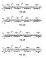
- FIG. 1illustrates a time period including exemplary time period layout parameters, and exemplary subdivisions of the time period including frames, sub-frames, smaller time period components, and even smaller time period components.
- FIG. 2 aillustrates a time period layout including an exemplary frame.
- FIG. 2 billustrates a time period layout including multiple frames of the same size.
- FIG. 2 cillustrates a time period layout including multiple frames of different sizes.
- FIG. 2 dillustrates a time period layout including multiple frames of the same size that are each subdivided into sub-frames of the same size.
- FIG. 2 eillustrates a time period layout including multiple frames of the same size that are each subdivided into sub-frames of different sizes.
- FIG. 2 fillustrates a time period layout including multiple frames of different sizes that are each subdivided into sub-frames of the same size.
- FIG. 2 gillustrates a time period layout including multiple frames of different sizes that are each subdivided into sub-frames of different sizes.
- FIG. 2 hillustrates a time period layout including multiple same-size frames and same-size sub-frames combined with smaller components of the same size.
- FIG. 2 iillustrates a time period layout including multiple same-size frames and same-size sub-frames combined with smaller components of different sizes.
- FIG. 2 jillustrates a time period layout including multiple same-size frames and different-size sub-frames combined with smaller components of the same size.
- FIG. 2 killustrates a time period layout including multiple same-size frames and different-size sub-frames combined with smaller components of different sizes.
- FIG. 2 lillustrates a time period layout including multiple different-size frames and same-size sub-frames combined with smaller components of the same size.
- FIG. 2 millustrates a time period layout including multiple different-size frames and same-size sub-frames combined with smaller components of different sizes.
- FIG. 2 nillustrates a time period layout including multiple different-size frames and different-size sub-frames combined with smaller components of the same size.
- FIG. 2 oillustrates a time period layout including multiple different-size frames and different-size sub-frames are combined with smaller components of different sizes.
- FIG. 3 aillustrates a code mapping approach, depicting pulses mapped to sub-frames based on integer code element values of a time-hopping code, where an integer code element exists per frame and pulses are positioned within sub-frames using an absolute or relative position offset.
- FIG. 3 billustrates a code mapping approach, depicting pulses mapped to sub-frames that are numbered in sequence across a time period, where integer code element values of a time-hopping code map to the sequentially numbered sub-frames.
- FIG. 4 aillustrates mapping pulses to positions within frames based on floating-point code element values of a time-hopping code, where a floating-point code element exists per frame.
- FIG. 4 billustrates mapping pulses to frames within a time period using the non-fractional part of a floating point code element value of a time-hopping code and mapping pulses to positions within frames using the fractional part of the floating-point code element values.
- FIG. 5 aillustrates an exemplary embodiment of a least significant bit/most significant bit (LSB/MSB) mapping approach.
- FIG. 5 billustrates another exemplary embodiment of a least significant bit/most significant bit (LSB/MSB) mapping approach.
- FIG. 6 ais a diagram of a binary linear feedback shift-register pseudorandom number generator.
- FIG. 6 bis a diagram of an additive Lagged-Fibonacci shift register pseudorandom number generator.
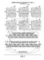
- FIG. 7depicts generation of family of quadratic congruential codes comprising 6 channels, mapping of the 5 th channel code to a time period layout, and the code wrapping effect that occurs due to the code repeating over time.
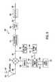
- FIG. 8is a block diagram of an impulse transmitter that advantageously uses the present invention.
- FIG. 9is a block diagram of an impulse transmitter that advantageously uses the present invention.
- FIG. 10illustrates autocorrelation properties of the 5 th channel code of FIG. 7 .
- FIG. 11is a plot diagram for illustrating the number of coincidences against a time offset in the example of FIG. 7 .
- FIG. 12is an example embodiment of a plot illustrating moving and re-plotting the data of FIG. 1 producing an exemplary ‘thumbtack’ plot.
- FIG. 13illustrates cross-correlation properties of the 6 th channel code relative to the 5 th channel code of FIG. 7 .
- FIG. 14is an example embodiment of a plot illustratively plotting coincidences of the cross-correlation of the 6 th and 5 th codes of FIG. 7 by time offset.
- the present inventionprovides a method of using a generated code to specify positions and other characteristics of pulses within a pulse train.
- each generated codeconsists of a set or a number of code element values.
- the method of the inventioninvolves defining a layout of the time period over which the pulses arc overlaid.
- a mapping approachmaps the code element values to pulse positions over the layout based on the generated code.
- the codeis generated using a numerical code generation technique, and code element values are mapped to pulse positions in accordance with the defined time period layout and code mapping approach.
- a sequence of pulses known as a pulse trainis transmitted and received over a period of time such that the relative positioning of the pulses in time defines a channel used by the system to transmit information.
- These pulse trains or some combination of different pulse trainsrepeat over time such that the minimum time value of a time period containing a pulse train occurs at the same time as the maximum time value of the preceding time period containing the preceding pulse train.
- Time period(s)can be laid out in a multitude of ways to accommodate a wide variety of pulse transmission system applications.
- One approachinvolves a value range layout where a period of time is divided into smaller and smaller components. The division is used to achieve a desired component resolution in order to facilitate mapping of a code element value to a time position value that resides within a layout component, which corresponds to some range of time values.
- FIG. 1includes a time period layout.
- Multiple frame sizesmay be employed to accommodate multiple data stream systems, to add an encryption dimension, and/or for many other purposes.
- one or more acquisition frames and/or one or more header framescan be intermixed with one or more frames containing user data, wherein the acquisition, header, and user data frames have different sizes.
- same size flamesmay be employed such that acquisition, header, and user data are combined into a single data stream that is deciphered via a communications protocol once the data stream is captured.
- the number and size of frames used in a given layoutcan also be tailored to meet specific application requirements. They can also be used to remain within system implementation limits, to achieve one or more of a variety of system characteristics in areas such as performance (i.e., bit rate), reliability (i.e., bit error rate), system-simplicity, ease-of-use, etc., and/or for many other reasons.
- minimum and maximum time valuesare specified for each frame n.
- the minimum time value for a given frame, t min (n)may equal the maximum time value of the preceding frame, t max (n ⁇ 1), or t 0 .
- the maximum time value of a given frame, t max (n)may equal the minimum time value for the following frame, t min (n+1), or t max .
- the time period layoutis evenly divided such that t max (n) ⁇ t min (n) is equal for each frame n.
- N framesAn array of layout parameters, N sub-frames (N frames ), can be specified to subdivide frames 104 into sub-frames 106 .
- Multiple sub-frame sizesmay be employed to accommodate multiple bit rates, to achieve desirable correlation properties, to add an encryption dimension, and/or for many other purposes.
- the number and size of sub-frames for a given frame used in a given time period layoutcan also be tailored to meet specific application requirements. These parameters may also be selected to remain within system implementation limits, to achieve one or more of a variety of system characteristics in areas such as performance (i.e., bit rate), reliability (i.e., hit error rate), system-simplicity, ease-of-use, etc., and/or for many other reasons.
- performancei.e., bit rate
- reliabilityi.e., hit error rate
- system-simplicityi.e., ease-of-use, etc.
- minimum and maximum time valuesare specified for each sub-frame m of each frame (n).
- the minimum time value for a given sub-frame, t min (n,m)may equal the maximum time value of the preceding sub-frame, t max (n,m ⁇ 1), or the minimum time value of the frame in which the sub-frame resides, t min (n).
- the maximum time value of a given sub-frame, t max (m,n)may equal the minimum time value for the following sub-frame, t min (n,m+1), or the maximum time value of the frame in which the sub-frame resides, t max (n).
- framesmay be evenly divided.
- t max (n,m) ⁇ t min (n,m)may be equal for each sub-frame m of a frame n or for all frames such that all sub-frames of a given frame are of the same size.
- the sub-frame sizesmay vary from frame to frame or all sub-frames of all frames arc of the same size depending on the sizes of the frames and the numbers of sub-frames in the frames.
- additional multi-dimensional arrays of layout parameterscan be used to further subdivide sub-frames 106 into smaller components 108 of the same or different sizes, ad infinitum. This subdivision may continue until a smallest desirable time component resolution is attained.
- sub-framesSuch further subdivision of sub-frames into smaller and smaller time components enables systems with finer and finer tuning resolution and thus higher and higher fidelity, increases modulation timing accuracy, and can be useful for other purposes.
- the number and size of these smaller time componentscan also be tailored to meet specific application requirements. These parameters can also be tailored to remain within system implementation limits, to achieve one or more of a variety of system characteristics in areas such as performance (i.e., bit rate), reliability (i.e., bit error rate), system-simplicity, ease-of-use, etc., and/or for many other reasons.
- minimum and maximum time valuesare specified for each time component ( ⁇ ).
- the minimum time value for a component, t min (n,m, . . . , ⁇ ),may be equal to the maximum time value of the preceding component, t max (n,m, . . . , ⁇ 1), or the minimum time value of the next higher-level time component in which the time component resides, t min (n,m, . . . ).
- the maximum time value of a given time component, t max (n,m, . . . ⁇ )may be equal to the minimum time value for the following component, t min (n,m, . . . ⁇ +1) or the maximum time value of the next higher level time component in which the time component resides, t max (n,m, . . .
- next higher-level componentsmay be evenly divided. Consequently, t max (n,m, . . . ⁇ ) ⁇ t min (n,m, . . . ⁇ ) may be equal for each time component of a given next higher level component.
- all time components of a given next higher-level componentmay be of the same or different size. Under one arrangement, the time component sizes may vary from next higher-level component to next higher-level component. Alternatively, all time components of all higher-level components may be of the same size, depending on the sizes of the next higher-level components and the numbers of time components in the next higher-level components.
- a time period layout 102is depicted that is bounded by endpoints of t 0 110 and t max 112 .
- an equivalent time period layout 102is shown that has been subdivided into four frames 104 by setting the layout parameter N frames to a value of four (4).
- An enlargement of the second frame 104is then shown where the frame 104 is subdivided into twenty sub-frames 106 by setting the layout parameter N sub-frames (2) to a value of twenty (20).
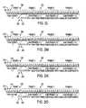
- FIGS. 2 a through 2 oprovide examples of different types of time period layouts that can be established. This group of figures illustrates layout permutations involving nesting of up to three levels of time components, which could be subdivided further to additional levels, ad infinitum, to produce additional permutations.
- FIG. 2 adepicts an exemplary embodiment of a time period layout 202 consisting of a single frame (not labeled).
- FIGS. 2 b and 2 cpresent exemplary embodiments of time period layouts 202 that consist of multiple frames of the same size 204 , 206 and of different sizes 208 , 210 , respectively.
- frame 1 204is shown to be the same size as frame 2 206 .
- frame 1 208is shown as a different size than frame 2 210 .It will be apparent to those skilled in the art that other frame size configurations are possible, such as, e.g., a subset of frames being the same size and another subset of frames being of a different size, and that the exact relative frame size illustrations are intended to be illustrative, but not limiting.
- FIGS. 2 d and 2 eillustrate exemplary embodiments of time period layouts 202 consisting of multiple frames of the same size 204 , 206 that are each subdivided into sub-frames of the same size 212 , 214 or of different sizes 216 , 218 , respectively.
- frame 1 204is the same size as frame 2 206
- the sub-frames 212 , 214 of frame 1 204are of the same size.
- frame 1 204is of the same size than frame 2 206 , but sub-frames 216 , 218 of frame 1 204 are of different sizes.
- FIGS. 2 f and 2 gillustrate time period layouts 202 consisting of multiple frames of different sizes 208 , 210 that are each subdivided into sub-frames of the same size 212 , 214 or of different sizes 216 , 218 , respectively.
- frame 1 208is of a different size than frame 2 210
- the sub-frames 212 , 214 of frame 1 208are of the same size.
- frame 1 208is of a different size than frame 2 210
- sub-frames 216 , 218 of frame 1 208are of different sizes.
- FIGS. 2 h and 2 isame-size frames 204 , 206 and same-size sub-frames 212 , 214 are combined with smaller components of the same size 220 , 222 and of different sizes 224 , 226 , respectively.
- FIGS. 2 h and 2 iare the same.
- the sub-frames of FIG. 2 hhave smaller components 220 , 222 that are of the same size
- the sub-frame of FIG. 2 ihave smaller components 224 , 226 that are of different sizes.
- FIGS. 2 j and 2 ksame-size frames 204 , 206 and different-size sub-frames 216 , 218 are combined with smaller components of the same size 220 , 222 and of different sizes 224 , 226 , respectively.
- FIGS. 2 j and 2 kare the same.
- the sub-frames of FIG. 2 jhave smaller components 220 , 222 that are of the same size
- the sub-frames of FIG. 2 khave smaller components 224 , 226 that are of different sizes.
- FIGS. 2 l and 2 mdifferent-size frames 208 , 210 and same-size sub-frames 212 , 214 are combined with smaller components of the same size 220 , 222 and of different sizes 224 , 226 , respectively
- FIGS. 2 l and 2 mare the same.
- the sub-frames of FIG. 2 lhave smaller components 220 , 222 that are of the same size
- the sub-frames of FIG. 2 mhave smaller components 224 226 that are of different sizes.
- FIGS. 2 n and 2 odifferent-size frames 208 , 210 and different-size sub-frames 216 , 218 are combined with smaller components of the same size 220 , 222 and of different sizes 224 , 226 , respectively.
- FIGS. 2 n and 2 oare the same.
- the sub-frames of FIG. 2 nhave smaller components 224 , 226 that arc of the same size
- the sub-frames of FIG. 2 ohave smaller components 224 , 226 that are of different sizes.
- Another approach to defining a time layoutis to specify discrete time position values to which individual code elements can map.
- code elementsmap to an exact time position instead of a range of time bounded by frame, sub-frame, or smaller time period component minimum and maximum time values.
- a time period layoutcan also be defined as a non-fixed layout, which is also referred to as a delta value layout.
- a ‘fixed’ layoutdefines a range of time values between t 0 and t max
- a ‘non-fixed’ time period layoutdefines a range of delta time values between ⁇ t 0 and ⁇ t max .
- the delta time value rangecan be divided into frames, sub-frames, and smaller components in the same manner as a fixed time period layout. This non-fixed layout approach depends on the time position of the previous pulse in that the time position of a given pulse equals the time position of the previous pulse plus a delta value determined by mapping a code element value to a non-fixed time layout.
- a time-hopping codeis comprised of elements having either integer or floating-point values. As a minimum, these values map pulses to specific time positions within the defined layout.
- a given frame, sub-frame, or smaller time period componentcan contain zero, one, or more pulses, and the value of each integer code element or the non-fractional part of each floating-point code element value identifies a frame, sub-frame or smaller time period component in which a pulse may be placed.
- a time-hopping codecan also contain additional elements used to specify other pulse characteristics such as amplitude, width, type and/or whether a pulse should be inverted. Additionally, a number within a code can be a single element value or can represent a combination of multiple element values.
- the numbering scheme used for a codemust be consistent with the numbering scheme used for the defined time period layout to allow mapping of code element values to positions within time period components.
- Componentsmay be numbered beginning with zero, one, or with any other number.
- Components produced by subdividing higher level components, such as sub-frames or smaller time period componentsmay be numbered per higher level component such that sub-component numbering begins again with each higher level component, or may be numbered in sequence independent of the higher level component in which they reside.
- an established offset valuecan be used to specify the exact position of the pulse within the frame, sub-frame, or smaller time period component.
- An absolute offset valuecan be used to position pulses a common distance in time from the minimum time values of the frames, sub-frames, or smaller time period components to which code elements are mapped.
- a relative position offset valuecan be used to position pulses a fraction of the distance in time between the minimum and maximum time values of the frames, sub-frames, or smaller time period components to which code elements are mapped.
- the fractional part of each floating-point code elementcan be used.
- the fractional partcould specify the relative offset used to position a pulse a fraction of the distance in time between the minimum and maximum time values of the frame, sub-frame, or smaller time component to which the non-fractional part of the floating-point code element is mapped.
- the fractional portions of floating-point valuescan vary per code element allowing each pulse position to be established independent of other pulses.
- FIGS. 3 a and 3 billustrate exemplary embodiments of the component numbering and code mapping approaches involving integer code element values.
- FIG. 3 adepicts a diagram 300 of an exemplary embodiment illustrating pulses 310 mapped to sub-frames 312 numbered per frame 308 , where an integer code element 306 a - 306 d of a code 304 exists per frame 308 of a layout 302 .
- FIG. 3 bshows a diagram 320 of an exemplary embodiment illustrating pulses 330 napped to sub-frames 332 that are numbered in sequence across the time period layout 322 independent of frames 328 , where an integer code element 326 e - 326 h of a code 324 exists per pulse.
- the exact positions of the pulses 310 , 330 within the sub-frames 312 , 332 specified by the two integer codes 304 , 324would be determined using either an absolute or relative position offset value. It should be noted that the two figures present two different methods for mapping codes to the same locations in the time period.
- the first sub-frame numbering methodis frame-dependent in that it maps one pulse and only one pulse per frame, while the second sub-frame numbering method is frame-independent in that it can be used to map zero, one, or more pulses to a given frame.
- FIGS. 4 a and 4 bdepict two exemplary embodiments of the invention illustrating methods of mapping pulses to frames using floating-point values.
- each floating-point code element value 406 a - 406 d of a code 404maps a pulse 410 to a location that is a relative fraction 412 of the distance in time 414 between the minimum and maximum time values of each frame 408 within a time layout 402 , as defined by a fractional part of a code element value.
- each floating-point code element value 426 a - 426 g of a code 424maps a pulse 430 to a position that is a fraction 434 of the distance in time 436 between the minimum and time values of the frame 428 within a time layout 422 , as specified by the non-fractional part of the floating-code element value 432 a - 432 g of the code 424 .
- pulsesare positioned independent of each other.
- the first floating-point code methodis frame-dependent such that it positions one pulse and only one pulse per frame, while the second method is frame-independent enabling zero, one or more pulses to be positioned per frame.
- a bit-group mapping approachcan also be employed to map code elements to positions within a time period layout.
- a time component and a position offsetcan be specified by subdividing the binary representation of a code element value.
- the binary representationmay be divided into a plurality of subset of one or more bits.
- the binary representationmay be divided into a first sub set of bits, for example, the most significant bits (MSBs) and a second subset of bits, for example, the least significant bits (LSBs).
- the first subset of bitsmay specify the time period component in which to place a pulse and the second subset of bits specifies an absolute or relative position offset value.
- FIG. 5 aAn example of a LSB/MSB mapping approach is shown in FIG. 5 a .
- the decimal value 508 of each code element value 506 a - 506 g of a code 504is represented as a 16-bit binary word 510 that is subdivided into its eight MSBs 512 and its eight LSBs 514 .
- the binary value of the MSBsis translated into a decimal value 516 representing the frame 522 in which to place a pulse 524 .
- the binary value of the LSBsis translated into a decimal value that is then divided by 100 in order to produce a value representing the desired offset fraction 518 used to specify the exact position of a pulse 524 within the frame 522 specified by the translated MSBs 516 .
- the translated MSB and LSB values 516 , 518 of each code element 506 a - 506 gcan also be combined into translated code elements ( 516 a - 516 g and 518 a - 518 g ) that are equivalent to the code elements shown in FIG. 4 b.
- the bits of a code elements binary representationcan also be subdivided into three or more subsets to enable-encoding of additional information such as whether or not a pulse is inverted, pulse amplitude, pulse width, pulse type, etc.
- FIG. 5 bis similar to FIG. 5 a except that it demonstrates a slightly more complex bit-group mapping approach.
- the decimal value 538 of each code element value 536 a - 536 g of a code 534is represented as a 16-bit binary word 540 that is subdivided into its eight MSBs 542 , its first seven LSBs 544 , and its last LSB 545 .
- the binary value of the MSBsis translated into a decimal value 546 representing the frame 552 in which to place a pulse 554 .
- the binary value of the first seven LSBsis translated into a decimal value that is then divided by 100 in order to produce a value representing the desired offset fraction 548 used to specify the exact position of a pulse 554 within the frame 552 specified by the translated MSBs 546 .
- the translated MSB and LSB values 545 , 546 , 548 of each code element 536 a - 536 gcan also be combined into translated code elements ( 545 a - 545 g , 546 a - 546 g and 548 a - 548 g ), where the first seven LSBs 544 are used to specify the offset fraction 548 and the last LSB 545 is used to specify whether or not a pulse is inverted.
- the translated bit patternsare shown combined into a translated code 549 that is the same as the translated code 519 shown in FIG. 5 a , except the first and fifth code element values are negative 545 a , 545 e to specify that the first and fifth pulses are to be inverted.
- Bit-group mappingmay be employed using binary word sizes that are 8-bit, 16-bit, and 32-bit or whatever size is deemed appropriate to encode data describing a pulse train. Given a word size, bits can be grouped as appropriate to encode the largest possible value for a given data item. For example, to encode offset fraction values with 2-digit precision, a group of 7 data bits is required to represent integer values from 0 to 100. Similarly, if 1000 frames exist in the time period, a group of 10 bits is required to represent integer values from 1 to 1000.
- bit-group mapping methodcan also be employed in combination with established absolute or relative offset values when common offset positions are appropriate.
- a time-hopping codeis generated using a numerical code generation technique.
- the autocorrelation and cross-correlation properties of a pulse trainmust be within certain limits to ensure proper signal locking and channelization.
- a codecan be generated using a quadratic congruential, hyperbolic congruential, linear congruential, Costas array or other such numerical code generation technique designed to generate codes guaranteed to have specific correlation properties.
- Quadratic congruential codeshave p elements and p 3 ⁇ p 2 different sequences can be generated by changing the value of parameters i, ⁇ , and , ⁇ .
- Quadratic congruential codeshave correlation properties that guarantee a maximum of two coincidences when autocorrelated with some time offset and a maximum of four coincidences when cross-correlated with another quadratic congruential code.
- Each hyperbolic congruential codehas p ⁇ 1 elements and p ⁇ 1 different sequences can be generated.
- Hyperbolic congruential codeshave correlation properties that guarantee a maximum of two coincidences when autocorrelated with some time offset and a maximum of two coincidences when cross-correlated with another hyperbolic congruential code.
- a linear congruential code of integer valuescan be generated using an equation of the general form: y i , ⁇ LC ⁇ ( k ) ⁇ ( ik + ⁇ ) ⁇ mod ⁇ ⁇ p 1 ⁇ i, k ⁇ p ⁇ 1; ⁇ 0, 1 , . . . , p ⁇ 1 ⁇ , where p is a prime number.
- Each linear congruential codehas p ⁇ 1 elements and p ⁇ 1 different sequences can be generated.
- Linear congruential codeshave correlation properties that guarantee a maximum of 1/1n(p ⁇ 1) coincidences when autocorrelated with some time offset and a maximum of 2/(p ⁇ 1) coincidences when cross-correlated with another linear congruential code.
- Each Welch-Costas codehas p ⁇ 1 elements and p 2 different sequences can be generated.
- Golumb-Costas codehas p ⁇ 2 elements and (p ⁇ 1) 2 different sequences can be generated.
- Each of these alternative code generation schemeshas corresponding characteristics to be considered in relation to the application of the pulse transmission system employing the code.
- Costas codeshave nearly ideal autocorrelation properties but somewhat less than ideal cross-correlation properties
- linear congruential codeshave nearly ideal cross-correlation properties but less than ideal autocorrelation properties.
- design tradeoffsrequire that a compromise between two or more code generation schemes be made such that a code is generated using a combination of two or more methods.
- An example of such a compromiseis an extended quadratic congruential code generation approach that uses two independent operators, where the first operator is linear and the second operator is quadratic. Accordingly, one, two, or more code generation schemes or combinations of such schemes can be employed to generate a code without departing from the scope of the invention.
- a pseudorandom codecan be generated using a computers random number generator, binary shift-register(s) mapped to binary words, a chaotic code generation scheme, or another well known technique.
- Such ‘random-like’ codesare attractive for certain applications since they tend to spread spectral energy over multiple frequencies while having ‘good enough’ correlation properties, whereas designed codes may have superior correlation properties but have spectral properties that may not be as suitable for a given application.
- Truly random numbersare serially uncorrelated such that any subsequence of numbers cannot be correlated with any other subsequence of numbers, may not repeat, and are uniform and unbiased.
- Pseudorandom codesexhibit the appearance of true randomness, but nevertheless have a specific number pattern that repeats after some period.
- LCG(a,c,m,x 0 )which determines the sequence generated.
- AFGAdditive Lagged-Fibonacci Generator
- FIG. 6 aillustratively depicts a block diagram 602 including an exemplary embodiment of an LCG linear feedback shift register, including exclusive OR logic gate 604 having two inputs 606 , 608 and one output 610 .
- Eight bit shift register 614(labeled bit 0 614 a through bit 7 614 h ) includes shift out output 612 coupled to input 606 of exclusive OR logic gate 604 .
- Bit 3 614 dis coupled to input 608 of exclusive OR logic gate 604
- output 610 of exclusive OR logic gate 604is coupled as shown to bit 7 614 h .
- the sequence of bits that is generateddepends on the initial shift-register state and which shift-register bit value 614 d , a i , is fed back into the exclusive-OR device 604 along with the shifted output 612 .
- the ALFG methodcan also be implemented using a shift register and a modulo adder device 618 , as shown in FIG. 6 b .
- FIG. 6 bdepicts diagram 616 including an eight-bit shift register having bit 0 628 a through bit 7 628 h .
- Diagram 616also includes addition modulo 2 device 618 having two inputs 620 (coupled to bit 7 628 h ) and 622 (coupled to bit 5 628 f ), and an output 624 which can be outputted and can be fed back into input 626 of the ALFG shift register at bit 0 628 a .
- a pulsemay be mapped or positioned anywhere within a time frame, subframe or other time component.
- the present inventionapplies to situations where no non-allowable region is specified within a layout.
- the code element valuesare mapped to specific pulse positions in time per the defined time period layout and the employed code mapping approach.
- the mathematics behind the numerical code generation techniquesassumes the components to which generated code element values are mapped form a contiguous configuration of same-sized components. As a result, codes may be mapped to any position within the components.
- the component configurationrepeats such that the first component of a given component configuration is contiguous with the last component of the preceding component configuration and the last component of a component configuration is contiguous with the first component of the next component configuration.
- FIG. 7depicts the generation of quadratic congruential codes 702 a - 702 f and the mapping of the 5 th code 702 e to a time period layout 704 where the assumptions of the numerical code generation technique are valid.
- Six codes 702 a - 702 f representing six channelsare produced and displayed in matrix form where the darkened squares 708 represent code element values.
- the six codes 702 a - 702 f presentedare ⁇ 0,1,4,2,2,4,1 ⁇ , ⁇ 0,2,1,4,4,1,2 ⁇ , ⁇ 0,3,5,6,6,5,3 ⁇ , ⁇ 0,4,2,1,1,2,4 ⁇ , ⁇ 0,5,6,3,3,6,5 ⁇ , and ⁇ 0,6,3,5,5,3,6 ⁇ .
- Each column kmaps to a frame 712 and the row y(k) highlighted for each column k represents the sub-frame 714 y(k) in which to place a pulse.
- the bottom of the figureillustrates how the time period layout 704 repeats. As shown, the last frame of a preceding time period 716 is contiguous with the first frame of a current time period 718 and the last frame of the current time period 718 is contiguous with the first frame of a following time period 720 . Thus, whenever the start of a time period is shifted in time by some offset, a code wrapping effect occurs.
- An exemplary embodiment of an impulse radio transmitter 802 of an impulse radio communication system having one subcarrier channelwill now be described with reference to FIG. 8 .
- the transmitter 802comprises a time base 804 that generates a periodic timing signal 807 .
- the time base 804typically comprises a voltage controlled oscillator (VCO), or the like, having a high timing accuracy and low jitter, on the order of picoseconds (ps).
- VCOvoltage controlled oscillator
- the voltage control to adjust the VCO center frequencyis set at calibration to the desired center frequency used to define the transmitters nominal pulse repetition rate.
- the periodic timing signal 807is supplied to a precision timing generator 808 .
- the precision timing generator 808supplies synchronizing signals 810 to the code source 812 and utilizes the code source output 814 together with an internally generated subcarrier signal (which is optional) and an information signal 817 to generate a modulated, coded timing signal 818 .
- the code source 812comprises a storage device such as a random access memory (RAM), read only memory (ROM), or the like, for storing suitable time-hopping codes and for outputting the time-hopping codes as a code signal 814 .
- RAMrandom access memory
- ROMread only memory
- maximum length shift registers or other computational meanscan be used to generate the time-hopping codes.
- An information source 820supplies the information signal 817 to the precision timing generator 808 .
- the information signal 817can be any type of intelligence, including digital bits representing voice, data, imagery, or the like, analog signals, or complex signals.
- a pulse generator 822uses the modulated, coded timing signal 818 as a trigger to generate output pulses.
- the output pulsesare sent to a transmit antenna 824 via a transmission line 827 coupled thereto.
- the output pulsesare converted into propagating electromagnetic pulses by the transmit antenna 824 .
- the electromagnetic pulsesare called the emitted signal, and propagate to an impulse radio receiver 902 , such as shown in FIG. 9 , through a propagation medium, such as air, in a radio frequency embodiment.
- the emitted signalis wide-band or ultrawide-band, approaching a monocycle pulse as in FIG. 3 a .
- the emitted signalcan be spectrally modified by filtering of the pulses. This filtering will usually cause each monocycle pulse to have more zero crossings (more cycles) in the time domain.
- the impulse radio receivercan use a similar waveform as the template signal in the cross correlator for efficient conversion.
- FIG. 9An exemplary embodiment of an impulse radio receiver 902 (hereinafter called the receiver) for the impulse radio communication system is now described with reference to FIG. 9 . More specifically, the system illustrated in FIG. 9 is for reception of digital data wherein one or more pulses are transmitted for each data bit.
- the receiverfor the impulse radio communication system is now described with reference to FIG. 9 . More specifically, the system illustrated in FIG. 9 is for reception of digital data wherein one or more pulses are transmitted for each data bit.
- the receiver 902comprises a receive antenna 904 for receiving a propagated impulse radio signal 907 .
- a received signal 908 from the receive antenna 904is coupled to a cross correlator or sampler 910 to produce a baseband output 912 .
- the cross correlator or sampler 910includes multiply and integrate functions together with any necessary filters to optimize signal to noise ratio.
- the receiver 902also includes a precision timing generator 914 , which receives a periodic timing signal 917 from a receiver time base 918 .
- This time base 918is adjustable and controllable in time, frequency, or phase, as required by the lock loop in order to lock on the received signal 908 .
- the precision timing generator 914provides synchronizing signals 920 to the code source 922 and receives a code control signal 924 from the code source 922 .
- the precision timing generator 914utilizes the periodic timing signal 917 and code control signal 924 to produce a coded timing signal 927 .
- the template generator 928is triggered by this coded timing signal 927 and produces a train of template signal pulses 930 ideally having waveforms substantially equivalent to each pulse of the received signal 908 .
- the code for receiving a given signalis the same code utilized by the originating transmitter 802 to generate the propagated signal 907 .
- the timing of the template pulse train 930matches the timing of the received signal pulse train 908 , allowing the received signal 908 to be synchronously sampled in the correlator 910 .
- the correlator 910ideally comprises a multiplier followed by a short-term integrator to sum the multiplier product over the pulse interval.
- the output of the correlator 910also called a baseband signal 912 , is coupled to a subcarrier demodulator 932 , which demodulates the subcarrier information signal from the subcarrier.
- the purpose of the optional subcarrier process, when used,is to move the information signal away from DC (zero frequency) to improve immunity to low frequency noise and offsets.
- the output of the subcarrier demodulator 932is then filtered or integrated in a pulse summation stage 934 .
- the pulse summation stageproduces an output representative of the sum of a number of pulse signals comprising a single data bit.
- the output of the pulse summation stage 934is then compared with a nominal zero (or reference) signal output in a detector stage 938 to determine an output signal 939 representing an estimate of the original information signal 817 .
- the baseband signal 912is also input to a lowpass filter 942 (also referred to as lock loop filter 942 ).
- a control loopcomprising the lowpass filter 942 , time base 918 , precision timing generator 914 , template generator 928 , and correlator 910 is used to generate a filtered error signal 944 .
- the filtered error signal 844provides adjustments to the adjustable time base 918 to time position the periodic timing signal 927 in relation to the position of the received signal 908 .
- transceiver embodimentsubstantial economy can be achieved by sharing part or all of several of the functions of the transmitter 802 and receiver 902 . Some of these include the time base 918 , precision timing generator 914 , code source 922 , antenna 904 , and the like.
- FIG. 10presents the autocorrelation properties of the 5 th code 702 e where the time period layout 704 shown in FIG. 7 is correlated against other instances of the time period that are incrementally shifting in time by offsets equal to multiples of the width of a sub-frame.
- the incremental time shiftingmay correspond to a synchronization process between an impulse receiver and a transmitter, for example, the receiver 802 and the transmitter 902 .
- an initial synchronization process between the impulse radio receiver and transmitter 802 and 902may involve performing an incremental time shifting or time wrapping of a transmitted code against the same code, which is known at the receiver a priori.
- FIG. 10presents the autocorrelation properties of the 5 th code 702 e where the time period layout 704 shown in FIG. 7 is correlated against other instances of the time period that are incrementally shifting in time by offsets equal to multiples of the width of a sub-frame.
- the incremental time shiftingmay correspond to a synchronization process between an impulse receiver and a transmitter, for example, the receiver 802
- FIG. 10illustrates how the wrapping effect takes place, where with each shift of the correlated time period, the last sub-frame is moved or wraps to the front of the time period.
- the striped bars 1002are used to identify the coincidences that occur when the time period is correlated against the shifted instances of itself, i.e., autocorrelated. Whenever a darkened sub-frame 1004 appears behind a striped bar 1002 , a coincidence occurs. Thus it can be seen that when correlated against itself with no time offset, a total of seven coincidences occur, while for other offsets the number of coincidences varies from zero to two.
- FIG. 11plots the number of coincidences versus the time offset (i.e., number of sub-frames shifted).
- FIG. 12plots the same data where the last half of the plot is moved to the front of the plots which is allowable due to the wrapping effect described previously. This moving and re-plotting of the data produces what is commonly referred to as a ‘thumbtack’ plot.
- FIG. 13presents the cross-correlation of the 5 th and 6 th codes, 702 e and 702 f .
- a time period produced by mapped the 6 th code 702 fis shown correlated against instances of the 5 th code 702 e that are incrementally shifted in time by offsets equal to multiples of the width of a sub-frame.
- the cross-correlation propertiesmay be important in reducing interference in a multiple access impulse radio system between the receivers and transmitters 802 and 902 .
- the striped bars 1302are used to identify coincidences that occur when the time period produced with the 6 th code 702 f is correlated against the shifted instances of a time period produced with the 5 th code 702 e .
- the coincidencescan be seen whenever a darkened sub-frame 1304 appears behind a striped bar 1302 . It should be noted that the-instances of the 5 th code 702 e shown in FIG. 13 are the same as those shown in FIG. 10 . The cross-correlation of these two codes is depicted in FIG. 14 , which shows the maximum number of coincidences that occurs is three.
- a coding method for a pulse position modulation communication systemspecifies pulse positioning over time in accordance with a time layout about a time reference. After generating a time-hopping code, the method of the invention maps pulses over the time layout based-on the time hopping code at any location within the time layout.
- the pulse positioningmay be relative to a time reference, for example, a time position of a pulse that may be a preceding pulse or a succeeding pulse.
- the time-hopping codemay have predefined properties, such as autocorrelation properties, cross-correlation properties, or spectral properties.
Landscapes
- Engineering & Computer Science (AREA)
- Computer Networks & Wireless Communication (AREA)
- Signal Processing (AREA)
- Mobile Radio Communication Systems (AREA)
Abstract
Description
where p is a prime number. Each quadratic congruential code has p elements and p3−p2different sequences can be generated by changing the value of parameters i, α, and , β. Quadratic congruential codes have correlation properties that guarantee a maximum of two coincidences when autocorrelated with some time offset and a maximum of four coincidences when cross-correlated with another quadratic congruential code.
where p is a prime number ≧2 and k−1is the unique inverse of k modulo p. Each hyperbolic congruential code has p−1 elements and p−1 different sequences can be generated. Hyperbolic congruential codes have correlation properties that guarantee a maximum of two coincidences when autocorrelated with some time offset and a maximum of two coincidences when cross-correlated with another hyperbolic congruential code.
where p is a prime number. Each linear congruential code has p−1 elements and p−1 different sequences can be generated. Linear congruential codes have correlation properties that guarantee a maximum of 1/1n(p−1) coincidences when autocorrelated with some time offset and a maximum of 2/(p−1) coincidences when cross-correlated with another linear congruential code.
where p is a prime number and R is a primitive element of p. Each Welch-Costas code has p−1 elements and p2different sequences can be generated. Welch-Costas codes have correlation properties that guarantee a maximum of one coincidence when autocorrelated with some time offset and a maximum of l coincidences when cross-correlated with another Welch-Costas code, where R1=R2l.
where p is a prime number and η is a primitive element of p. Each Golumb-Costas code has p−2 elements and (p−1)2different sequences can be generated. Golumb-Costas codes have correlation properties that guarantee a maximum of one coincidence when autocorrelated with some time offset and a maximum of l and m coincidences when cross-correlated with another Welch-Costas code, where η1=η2mand α1=α2l.
Xn=Axn−1+c(modm)
where n identifies a given code in the generated code sequence, and the generated sequence is characterized by the multiplier A, the additive constant c, the modulus m, and an initial seed x0. These random number generator functions can be referred to as LCG(a,c,m,x0), which determines the sequence generated.
xn=xn−j+xn−k(mod 2m),j<k
where n identifies a given code in the generated code sequence, and j and k represent offsets to previously generated codes. The period of these generators is (2k−1)2m−1and they are referred to as ALFG(l,k,m,x0), which determines the sequence generated.
where n identifies a given code in the generated code sequence, k is the number of bits in the shift register, aiis the value of the i-th bit in the shift register. The sequence of bits that is generated depends on the initial shift-register state and which shift-
xn=xn−j+xn−k(mod 2),j<k
where n identifies a given code in the generated code sequence, and j and k represent the shift-
Claims (28)
Priority Applications (3)
| Application Number | Priority Date | Filing Date | Title |
|---|---|---|---|
| US09/638,150US6959032B1 (en) | 2000-06-12 | 2000-08-15 | Method and apparatus for positioning pulses in time |
| AU2001269784AAU2001269784A1 (en) | 2000-06-12 | 2001-06-12 | Method for specifying pulse characteristics using codes |
| PCT/US2001/018795WO2001097477A2 (en) | 2000-06-12 | 2001-06-12 | Method for specifying pulse characteristics |
Applications Claiming Priority (2)
| Application Number | Priority Date | Filing Date | Title |
|---|---|---|---|
| US59224800A | 2000-06-12 | 2000-06-12 | |
| US09/638,150US6959032B1 (en) | 2000-06-12 | 2000-08-15 | Method and apparatus for positioning pulses in time |
Related Parent Applications (1)
| Application Number | Title | Priority Date | Filing Date |
|---|---|---|---|
| US59224800AContinuation-In-Part | 2000-06-12 | 2000-06-12 |
Publications (1)
| Publication Number | Publication Date |
|---|---|
| US6959032B1true US6959032B1 (en) | 2005-10-25 |
Family
ID=35115356
Family Applications (1)
| Application Number | Title | Priority Date | Filing Date |
|---|---|---|---|
| US09/638,150Expired - LifetimeUS6959032B1 (en) | 2000-06-12 | 2000-08-15 | Method and apparatus for positioning pulses in time |
Country Status (1)
| Country | Link |
|---|---|
| US (1) | US6959032B1 (en) |
Cited By (80)
| Publication number | Priority date | Publication date | Assignee | Title |
|---|---|---|---|---|
| US20040047285A1 (en)* | 2002-09-11 | 2004-03-11 | Foerster Jeffrey R. | Sub-banded ultra-wideband communications system |
| US20040057501A1 (en)* | 2002-09-23 | 2004-03-25 | Krishna Balachandran | Systems and methods for providing adaptive pulse position modulated code division multiple access for ultra-wideband communication links |
| US20040240527A1 (en)* | 2003-03-08 | 2004-12-02 | Giannakis Georgios B. | Multi-user interference resilient ultra wideband (UWB) communication |
| US20050031043A1 (en)* | 2003-07-30 | 2005-02-10 | Mitsubishi Denki Kabushiki Kaisha | Method for identifying the beginning of a UWB pulse sequence |
| US20050105588A1 (en)* | 2003-09-30 | 2005-05-19 | Giannakis Georgios B. | Digital carrier multi-band user codes for ultra-wideband multiple access |
| US20050105594A1 (en)* | 2003-09-30 | 2005-05-19 | Giannakis Georgios B. | Pulse shaper design for ultra-wideband communications |
| US20050117628A1 (en)* | 2002-08-12 | 2005-06-02 | Brethour Vernon R. | Method for generating communication signal sequences having desirable correlation properties and system for using same |
| US20050221760A1 (en)* | 2004-03-31 | 2005-10-06 | Tinsley Keith R | Pulse shaping signals for ultrawideband communication |
| US20060129850A1 (en)* | 2004-12-15 | 2006-06-15 | Microsoft Corporation | Ultra wide band power save |
| US20070121638A1 (en)* | 2005-11-30 | 2007-05-31 | Szczebak Edward J Jr | Method and system of communicating superframe data |
| US20070133462A1 (en)* | 2005-12-02 | 2007-06-14 | Telefonaktiebolaget Lm Ericsson (Publ) | Hopping pilot pattern for telecommunications |
| US20070143078A1 (en)* | 2001-03-26 | 2007-06-21 | Martin Vetterli | Sampling method, reconstruction method, and device for sampling and/or reconstructing signals |
| US20070270273A1 (en)* | 2006-05-18 | 2007-11-22 | Motorola, Inc. | Method and apparatus for fast cell search |
| US7576672B2 (en) | 2007-07-18 | 2009-08-18 | Qualcomm Incorporated | Adaptive Dynamic Range Control |
| US7576605B2 (en) | 2006-04-20 | 2009-08-18 | Qualcomm Incorporated | Low power output stage |
| US7592878B2 (en) | 2007-04-05 | 2009-09-22 | Qualcomm Incorporated | Method and apparatus for generating oscillating signals |
| US20100005371A1 (en)* | 2008-07-07 | 2010-01-07 | Qualcomm Incorporated | System and method of puncturing pulses in a receiver or transmitter |
| US7716001B2 (en) | 2006-11-15 | 2010-05-11 | Qualcomm Incorporated | Delay line calibration |
| US7812667B2 (en) | 2008-03-10 | 2010-10-12 | Qualcomm Incorporated | System and method of enabling a signal processing device in a relatively fast manner to process a low duty cycle signal |
| US20100284425A1 (en)* | 2009-05-11 | 2010-11-11 | David Hood | System and method of using tdm variable frame lengths in a telecommunications network |
| US7834482B2 (en) | 2007-04-23 | 2010-11-16 | Qualcomm Incorporated | Apparatus and method for generating fine timing from coarse timing source |
| US7855611B2 (en) | 2006-11-15 | 2010-12-21 | Qualcomm Incorporated | Delay line calibration |
| US7868689B2 (en) | 2008-04-08 | 2011-01-11 | Qualcomm Incorporated | Low power slicer-based demodulator for PPM |
| US7889753B2 (en) | 2006-11-16 | 2011-02-15 | Qualcomm Incorporated | Multiple access techniques for a wireless communication medium |
| US7903973B1 (en)* | 2005-12-23 | 2011-03-08 | Lockheed Martin Corporation | Dynamic temporal duration optical transmission privacy |
| US7965805B2 (en) | 2007-09-21 | 2011-06-21 | Qualcomm Incorporated | Signal generator with signal tracking |
| US7974580B2 (en) | 2007-08-28 | 2011-07-05 | Qualcomm Incorporated | Apparatus and method for modulating an amplitude, phase or both of a periodic signal on a per cycle basis |
| US8005065B2 (en) | 2007-09-11 | 2011-08-23 | Qualcomm Incorporated | Keep-alive for wireless networks |
| US8014425B2 (en) | 2006-11-16 | 2011-09-06 | Qualcomm Incorporated | Multiple access techniques for a wireless communiation medium |
| US20110231657A1 (en)* | 2009-03-16 | 2011-09-22 | Qualcomm Incorporated | Apparatus and method for employing codes for telecommunications |
| US8059573B2 (en) | 2007-07-30 | 2011-11-15 | Qualcomm Incorporated | Method of pairing devices |
| US8103228B2 (en) | 2007-07-12 | 2012-01-24 | Qualcomm Incorporated | Method for determining line-of-sight (LOS) distance between remote communications devices |
| US8165080B2 (en) | 2008-08-22 | 2012-04-24 | Qualcomm Incorporated | Addressing schemes for wireless communication |
| WO2012065184A3 (en)* | 2010-11-12 | 2012-07-05 | Nextnav, Llc | Wide area positioning system |
| US8233572B2 (en) | 2007-09-25 | 2012-07-31 | Qualcomm Incorporated | Interference mitigation for impulse-based communication |
| US8254595B2 (en) | 2008-03-25 | 2012-08-28 | Qualcomm Incorporated | System and method of companding an input signal of an energy detecting receiver |
| US8275373B2 (en) | 2007-09-28 | 2012-09-25 | Qualcomm Incorporated | Randomization of periodic channel scans |
| US8275343B2 (en) | 2008-03-10 | 2012-09-25 | Qualcomm Incorporated | System and method of using residual voltage from a prior operation to establish a bias voltage for a subsequent operation |
| US8289159B2 (en) | 2006-04-26 | 2012-10-16 | Qualcomm Incorporated | Wireless localization apparatus and method |
| US8326246B2 (en) | 2007-07-10 | 2012-12-04 | Qualcomm Incorporated | Super regenerative (SR) apparatus having plurality of parallel SR amplifiers tuned to distinct frequencies |
| US8363583B2 (en) | 2006-12-15 | 2013-01-29 | Qualcomm Incorporated | Channel access scheme for ultra-wide band communication |
| US8385474B2 (en) | 2007-09-21 | 2013-02-26 | Qualcomm Incorporated | Signal generator with adjustable frequency |
| US8406794B2 (en) | 2006-04-26 | 2013-03-26 | Qualcomm Incorporated | Methods and apparatuses of initiating communication in wireless networks |
| US8446976B2 (en) | 2007-09-21 | 2013-05-21 | Qualcomm Incorporated | Signal generator with adjustable phase |
| US8451710B2 (en) | 2006-04-26 | 2013-05-28 | Qualcomm Incorporated | Sub-packet pulse-based communications |
| US8473013B2 (en) | 2008-04-23 | 2013-06-25 | Qualcomm Incorporated | Multi-level duty cycling |
| US8483639B2 (en) | 2008-05-06 | 2013-07-09 | Qualcomm Incorporated | AGC for slicer-based low power demodulator |
| US8514911B2 (en) | 2009-05-13 | 2013-08-20 | Qualcomm Incorporated | Method and apparatus for clock drift compensation during acquisition in a wireless communication system |
| US8538345B2 (en) | 2007-10-09 | 2013-09-17 | Qualcomm Incorporated | Apparatus including housing incorporating a radiating element of an antenna |
| US8553744B2 (en) | 2009-01-06 | 2013-10-08 | Qualcomm Incorporated | Pulse arbitration for network communications |
| US8552903B2 (en) | 2006-04-18 | 2013-10-08 | Qualcomm Incorporated | Verified distance ranging |
| US8589720B2 (en) | 2008-04-15 | 2013-11-19 | Qualcomm Incorporated | Synchronizing timing mismatch by data insertion |
| US8600373B2 (en) | 2006-04-26 | 2013-12-03 | Qualcomm Incorporated | Dynamic distribution of device functionality and resource management |
| US8612693B2 (en) | 2009-03-19 | 2013-12-17 | Qualcomm Incorporated | Optimized transfer of packets in a resource constrained operating environment |
| US8629803B2 (en) | 2008-09-10 | 2014-01-14 | Nextnav, Llc | Wide area positioning system |
| US8644396B2 (en) | 2006-04-18 | 2014-02-04 | Qualcomm Incorporated | Waveform encoding for wireless applications |
| US8787440B2 (en) | 2008-07-25 | 2014-07-22 | Qualcomm Incorporated | Determination of receive data values |
| US8811456B2 (en) | 2006-04-19 | 2014-08-19 | Qualcomm Incorporated | Apparatus and method of low latency multi-hop communication |
| US8837724B2 (en) | 2007-03-27 | 2014-09-16 | Qualcomm Incorporated | Synchronization test for device authentication |
| US8874398B2 (en) | 2010-11-12 | 2014-10-28 | Nextnav, Llc | Wide area positioning system |
| US8886125B2 (en) | 2006-04-14 | 2014-11-11 | Qualcomm Incorporated | Distance-based association |
| US8917209B2 (en) | 2009-09-10 | 2014-12-23 | Nextnav, Llc | Coding in a wide area positioning system (WAPS) |
| US9035829B2 (en) | 2008-09-10 | 2015-05-19 | Nextnav, Llc | Wide area positioning systems and methods |
| US9083448B2 (en) | 2007-10-26 | 2015-07-14 | Qualcomm Incorporated | Preamble capture and medium access control |
| US9124357B2 (en) | 2006-04-20 | 2015-09-01 | Qualcomm Incorporated | Media access control for ultra-wide band communication |
| US9141961B2 (en) | 2007-06-20 | 2015-09-22 | Qualcomm Incorporated | Management of dynamic mobile coupons |
| US9176217B2 (en) | 2011-08-02 | 2015-11-03 | Nextnav, Llc | Cell organization and transmission schemes in a wide area positioning system (WAPS) |
| US9215581B2 (en) | 2006-04-14 | 2015-12-15 | Qualcomm Incorported | Distance-based presence management |
| US9247392B2 (en) | 2012-06-05 | 2016-01-26 | Nextnav, Llc | Systems and methods for location positioning of user device |
| US9286490B2 (en) | 2013-09-10 | 2016-03-15 | Nextnav, Llc | Systems and methods for providing conditional access to transmitted information |
| US9291712B2 (en) | 2009-09-10 | 2016-03-22 | Nextnav, Llc | Cell organization and transmission schemes in a wide area positioning system (WAPS) |
| US9372266B2 (en) | 2009-09-10 | 2016-06-21 | Nextnav, Llc | Cell organization and transmission schemes in a wide area positioning system (WAPS) |
| US9390279B2 (en) | 2012-09-11 | 2016-07-12 | Nextnav, Llc | Systems and methods for providing conditional access to transmitted information |
| US9483769B2 (en) | 2007-06-20 | 2016-11-01 | Qualcomm Incorporated | Dynamic electronic coupon for a mobile environment |
| US9524502B2 (en) | 2007-06-20 | 2016-12-20 | Qualcomm Incorporated | Management of dynamic electronic coupons |
| US20180114477A1 (en)* | 2016-09-25 | 2018-04-26 | Fusao Ishii | Sequence and timing control of writing and rewriting pixel memories with substantially lower data rate |
| US10542372B2 (en) | 2011-03-15 | 2020-01-21 | Qualcomm Incorporated | User identification within a physical merchant location through the use of a wireless network |
| WO2021078816A3 (en)* | 2019-10-23 | 2021-06-24 | Fraunhofer-Gesellschaft zur Förderung der angewandten Forschung e.V. | Unipolar binary sequences having improved non-periodic correlation behaviour for unsynchronised tsma systems |
| US20210344543A1 (en)* | 2020-04-30 | 2021-11-04 | Qualcomm Incorporated | Peak-to-average power ratio reduction with pseudo-random in-band tone reservation |
| US20220352924A1 (en)* | 2015-02-09 | 2022-11-03 | Elmer Griebeler | Electromagnetic Communication Method |
Citations (14)
| Publication number | Priority date | Publication date | Assignee | Title |
|---|---|---|---|---|
| US3728632A (en) | 1971-03-12 | 1973-04-17 | Sperry Rand Corp | Transmission and reception system for generating and receiving base-band pulse duration pulse signals without distortion for short base-band communication system |
| US4170757A (en) | 1977-12-30 | 1979-10-09 | The United States Of America As Represented By The Secretary Of The Army | Method of and apparatus for transmitting clandestine radio signals |
| US4641317A (en) | 1984-12-03 | 1987-02-03 | Charles A. Phillips | Spread spectrum radio transmission system |
| US4743906A (en) | 1984-12-03 | 1988-05-10 | Charles A. Phillips | Time domain radio transmission system |
| US4813057A (en) | 1984-12-03 | 1989-03-14 | Charles A. Phillips | Time domain radio transmission system |
| US4928316A (en) | 1988-02-04 | 1990-05-22 | Bell Communications Research, Inc. | Optical systems and methods based upon temporal stretching, modulation and recompression of ultrashort pulses |
| US5363108A (en) | 1984-12-03 | 1994-11-08 | Charles A. Phillips | Time domain radio transmission system |
| US5377225A (en) | 1993-10-19 | 1994-12-27 | Hughes Aircraft Company | Multiple-access noise rejection filter for a DS-CDMA system |
| US5610907A (en) | 1994-07-29 | 1997-03-11 | Barrett; Terence W. | Ultrafast time hopping CDMA-RF communications: code-as-carrier, multichannel operation, high data rate operation and data rate on demand |
| US5677927A (en) | 1994-09-20 | 1997-10-14 | Pulson Communications Corporation | Ultrawide-band communication system and method |
| US5687169A (en) | 1995-04-27 | 1997-11-11 | Time Domain Systems, Inc. | Full duplex ultrawide-band communication system and method |
| US5793759A (en) | 1995-08-25 | 1998-08-11 | Terayon Corporation | Apparatus and method for digital data transmission over video cable using orthogonal cyclic codes |
| US5832035A (en) | 1994-09-20 | 1998-11-03 | Time Domain Corporation | Fast locking mechanism for channelized ultrawide-band communications |
| US6160802A (en) | 1994-07-29 | 2000-12-12 | Barrett Holding, Llc | Ultrafast time hopping CDMA and TDMA RF and optical communications: code-as-carrier, multichannel operation, high data rate operation and data rate on demand |
- 2000
- 2000-08-15USUS09/638,150patent/US6959032B1/ennot_activeExpired - Lifetime
Patent Citations (17)
| Publication number | Priority date | Publication date | Assignee | Title |
|---|---|---|---|---|
| US3728632A (en) | 1971-03-12 | 1973-04-17 | Sperry Rand Corp | Transmission and reception system for generating and receiving base-band pulse duration pulse signals without distortion for short base-band communication system |
| US4170757A (en) | 1977-12-30 | 1979-10-09 | The United States Of America As Represented By The Secretary Of The Army | Method of and apparatus for transmitting clandestine radio signals |
| US4641317A (en) | 1984-12-03 | 1987-02-03 | Charles A. Phillips | Spread spectrum radio transmission system |
| US4743906A (en) | 1984-12-03 | 1988-05-10 | Charles A. Phillips | Time domain radio transmission system |
| US4813057A (en) | 1984-12-03 | 1989-03-14 | Charles A. Phillips | Time domain radio transmission system |
| US4979186A (en) | 1984-12-03 | 1990-12-18 | Charles A. Phillips | Time domain radio transmission system |
| US5363108A (en) | 1984-12-03 | 1994-11-08 | Charles A. Phillips | Time domain radio transmission system |
| US4928316A (en) | 1988-02-04 | 1990-05-22 | Bell Communications Research, Inc. | Optical systems and methods based upon temporal stretching, modulation and recompression of ultrashort pulses |
| US5377225A (en) | 1993-10-19 | 1994-12-27 | Hughes Aircraft Company | Multiple-access noise rejection filter for a DS-CDMA system |
| US5610907A (en) | 1994-07-29 | 1997-03-11 | Barrett; Terence W. | Ultrafast time hopping CDMA-RF communications: code-as-carrier, multichannel operation, high data rate operation and data rate on demand |
| US6160802A (en) | 1994-07-29 | 2000-12-12 | Barrett Holding, Llc | Ultrafast time hopping CDMA and TDMA RF and optical communications: code-as-carrier, multichannel operation, high data rate operation and data rate on demand |
| US5677927A (en) | 1994-09-20 | 1997-10-14 | Pulson Communications Corporation | Ultrawide-band communication system and method |
| US5832035A (en) | 1994-09-20 | 1998-11-03 | Time Domain Corporation | Fast locking mechanism for channelized ultrawide-band communications |
| US5960031A (en) | 1994-09-20 | 1999-09-28 | Time Domain Corporation | Ultrawide-band communication system and method |
| US5963581A (en) | 1994-09-20 | 1999-10-05 | Time Domain Corporation | Ultrawide-band communication system and method |
| US5687169A (en) | 1995-04-27 | 1997-11-11 | Time Domain Systems, Inc. | Full duplex ultrawide-band communication system and method |
| US5793759A (en) | 1995-08-25 | 1998-08-11 | Terayon Corporation | Apparatus and method for digital data transmission over video cable using orthogonal cyclic codes |
Non-Patent Citations (12)
| Title |
|---|
| A. Albicki et al., "Transmitter And Receiver Design For Pilot Project, Phase 1", Technical Report #1, for Rochester Gas and Electric Corporation, pp. 726-742, (1988). |
| Bellegarda et al., "Amendment to time-Frequency Hop Codes Based Upon Extended Quadratic Congruences", IEEE Transactions On Aerospace And Electronic Systems, vol. 27(1):167-172, (1991). |
| Bellegarda et al., "The Hit Array: An Analysis Formalism For Multiple Access Frequency Hop Coding", IEEE Transactions On Aerospace And Electronic Systems, vol. 27(1):30-39,(1991). |
| Bellegarda et al., "Time-Frequency Hop Codes Based Upon Extended Quadratic Congrences", IEEE Transactions On Aerospace And Electronic Systems, vol. 24(6):726-742, (1988). |
| Comments of Pulson Communications Corporation before the Federal Communications Commission, 1992. |
| Drumheller et al., "Cross-Correlation Properties Of Algebraically Constructed Costas Arrays", IEEE Transactions On Aerospace And Electronic Systems, vol. 27:2-10, (1991). |
| E. L Titlebaum et al., "Time-Frequency Hop Signals Part I: Coding Based Upon The Theory Of Linear Congruences", IEEE Transactions On Aerospace And Electronic Systems, vol. AES-17(4):490-493, (1981). |
| E. L. Titlebaum et al., "Time-Frequency Hop Signals Part II: Coding Based Upon Quadratic Congruences", IEEE Transactions On Aerospace And Electronic Systems, vol. AES-17(4):494-500, (1981). |
| E.L. Titlebaum et al., "Ambiguity Properties Of Quadratic Congruential Coding", IEEE Transactions On Aerospace And Electronic Systems, vol. 27(1): 18-29, (1991). |
| Kostic et al., "The Design Of New Opitcal Codes And Time-Hopping Patterns For Synchronous Spread-Spectrum Code Division Multiple-Access Communication Systems", IEEE, ICC, pp. 585-589, (1991). |
| R.A. Scholtz, "Multiple Access With Time-Hopping Implulse Modulation", Communication Science Institute, University of Southern California, Los Angeles, CA (1993). |
| S.V. Maric et al., "A Class of Frequency Hop Codes With Nearly Ideal Characteristics For Use In Multiple-Access Spread-Spectrum Communications And Radar And Sonar Systems", IEEE Transactions ofn Communications, vol. 40(9):1442-1447, (1992). |
Cited By (119)
| Publication number | Priority date | Publication date | Assignee | Title |
|---|---|---|---|---|
| US8160194B2 (en) | 2001-03-26 | 2012-04-17 | Qualcomm Incorporated | Sampling method, reconstruction method, and device for sampling and/or reconstructing signals |
| US8077757B2 (en) | 2001-03-26 | 2011-12-13 | Qualcomm Incorporated | Sampling method for a spread spectrum communication system |
| US8031820B2 (en) | 2001-03-26 | 2011-10-04 | Qualcomm Incorporated | Sampling method, reconstruction method, and device for sampling and/or reconstructing signals |
| US20070143078A1 (en)* | 2001-03-26 | 2007-06-21 | Martin Vetterli | Sampling method, reconstruction method, and device for sampling and/or reconstructing signals |
| US7991095B2 (en) | 2001-03-26 | 2011-08-02 | Qualcomm Incorporated | Sampling method, reconstruction method, and device for sampling and/or reconstructing signals |
| US7675960B2 (en)* | 2002-08-12 | 2010-03-09 | Alereon, Inc. | Method for generating communication signal sequences having desirable correlation properties and system for using same |
| US20050117628A1 (en)* | 2002-08-12 | 2005-06-02 | Brethour Vernon R. | Method for generating communication signal sequences having desirable correlation properties and system for using same |
| US7400666B2 (en)* | 2002-08-12 | 2008-07-15 | Alereon, Inc. | Method for generating communication signal sequences having desirable correlation properties and system for using game |
| US20090022207A1 (en)* | 2002-08-12 | 2009-01-22 | Alereon, Inc. | Method for Generating Communication Signal Sequences Having Desirable Correlation Properties and System for Using Same |
| US20040047285A1 (en)* | 2002-09-11 | 2004-03-11 | Foerster Jeffrey R. | Sub-banded ultra-wideband communications system |
| US7532564B2 (en)* | 2002-09-11 | 2009-05-12 | Intel Corporation | Sub-banded ultra-wideband communications systems |
| US20040057501A1 (en)* | 2002-09-23 | 2004-03-25 | Krishna Balachandran | Systems and methods for providing adaptive pulse position modulated code division multiple access for ultra-wideband communication links |
| US7187715B2 (en)* | 2002-09-23 | 2007-03-06 | Lucent Technologies Inc. | Systems and methods for providing adaptive pulse position modulated code division multiple access for ultra-wideband communication links |
| US7496128B2 (en) | 2003-03-08 | 2009-02-24 | Regents Of The University Of Minnesota | Multi-user interference resilient ultra wideband (UWB) communication |
| US20040240527A1 (en)* | 2003-03-08 | 2004-12-02 | Giannakis Georgios B. | Multi-user interference resilient ultra wideband (UWB) communication |
| US7535983B2 (en)* | 2003-07-30 | 2009-05-19 | Mitsubishi Denki Kabushiki Kaisha | Method for identifying the beginning of a UWB pulse sequence |
| US20050031043A1 (en)* | 2003-07-30 | 2005-02-10 | Mitsubishi Denki Kabushiki Kaisha | Method for identifying the beginning of a UWB pulse sequence |
| US20050105594A1 (en)* | 2003-09-30 | 2005-05-19 | Giannakis Georgios B. | Pulse shaper design for ultra-wideband communications |
| US7561613B2 (en)* | 2003-09-30 | 2009-07-14 | Regents Of The University Of Minnesota | Digital carrier multi-band user codes for ultra-wideband multiple access |
| US20050105588A1 (en)* | 2003-09-30 | 2005-05-19 | Giannakis Georgios B. | Digital carrier multi-band user codes for ultra-wideband multiple access |
| US7738545B2 (en) | 2003-09-30 | 2010-06-15 | Regents Of The University Of Minnesota | Pulse shaper design for ultra-wideband communications |
| US7415245B2 (en) | 2004-03-31 | 2008-08-19 | Intel Corporation | Pulse shaping signals for ultrawideband communication |
| US20050221760A1 (en)* | 2004-03-31 | 2005-10-06 | Tinsley Keith R | Pulse shaping signals for ultrawideband communication |
| US7689843B2 (en)* | 2004-12-15 | 2010-03-30 | Microsoft Corporation | Ultra wide band power save |
| US20060129850A1 (en)* | 2004-12-15 | 2006-06-15 | Microsoft Corporation | Ultra wide band power save |
| US20070121638A1 (en)* | 2005-11-30 | 2007-05-31 | Szczebak Edward J Jr | Method and system of communicating superframe data |
| US20070133462A1 (en)* | 2005-12-02 | 2007-06-14 | Telefonaktiebolaget Lm Ericsson (Publ) | Hopping pilot pattern for telecommunications |
| US7711029B2 (en) | 2005-12-02 | 2010-05-04 | Telefonaktiebolaget Lm Ericsson (Publ) | Hopping pilot pattern for telecommunications |
| US7903973B1 (en)* | 2005-12-23 | 2011-03-08 | Lockheed Martin Corporation | Dynamic temporal duration optical transmission privacy |
| US9591470B2 (en) | 2006-04-14 | 2017-03-07 | Qualcomm Incorporated | System and method for enabling operations based on distance to and motion of remote device |
| US9510383B2 (en) | 2006-04-14 | 2016-11-29 | Qualcomm Incorporated | System and method of associating devices based on actuation of input devices and signal strength |
| US8886125B2 (en) | 2006-04-14 | 2014-11-11 | Qualcomm Incorporated | Distance-based association |
| US9215581B2 (en) | 2006-04-14 | 2015-12-15 | Qualcomm Incorported | Distance-based presence management |
| US8644396B2 (en) | 2006-04-18 | 2014-02-04 | Qualcomm Incorporated | Waveform encoding for wireless applications |
| US8552903B2 (en) | 2006-04-18 | 2013-10-08 | Qualcomm Incorporated | Verified distance ranging |
| US8654868B2 (en) | 2006-04-18 | 2014-02-18 | Qualcomm Incorporated | Offloaded processing for wireless applications |
| US8811456B2 (en) | 2006-04-19 | 2014-08-19 | Qualcomm Incorporated | Apparatus and method of low latency multi-hop communication |
| US7576605B2 (en) | 2006-04-20 | 2009-08-18 | Qualcomm Incorporated | Low power output stage |
| US9124357B2 (en) | 2006-04-20 | 2015-09-01 | Qualcomm Incorporated | Media access control for ultra-wide band communication |
| US8600373B2 (en) | 2006-04-26 | 2013-12-03 | Qualcomm Incorporated | Dynamic distribution of device functionality and resource management |
| US8406794B2 (en) | 2006-04-26 | 2013-03-26 | Qualcomm Incorporated | Methods and apparatuses of initiating communication in wireless networks |
| US8451710B2 (en) | 2006-04-26 | 2013-05-28 | Qualcomm Incorporated | Sub-packet pulse-based communications |
| US8289159B2 (en) | 2006-04-26 | 2012-10-16 | Qualcomm Incorporated | Wireless localization apparatus and method |
| US8553745B2 (en) | 2006-04-26 | 2013-10-08 | Qualcomm Incorporated | Inter-pulse duty cycling |
| US8527016B2 (en) | 2006-04-26 | 2013-09-03 | Qualcomm Incorporated | Wireless device communication with multiple peripherals |
| US20070270273A1 (en)* | 2006-05-18 | 2007-11-22 | Motorola, Inc. | Method and apparatus for fast cell search |
| US7716001B2 (en) | 2006-11-15 | 2010-05-11 | Qualcomm Incorporated | Delay line calibration |
| US8698572B2 (en) | 2006-11-15 | 2014-04-15 | Qualcomm Incorporated | Delay line calibration |
| US7855611B2 (en) | 2006-11-15 | 2010-12-21 | Qualcomm Incorporated | Delay line calibration |
| US7889753B2 (en) | 2006-11-16 | 2011-02-15 | Qualcomm Incorporated | Multiple access techniques for a wireless communication medium |
| US8014425B2 (en) | 2006-11-16 | 2011-09-06 | Qualcomm Incorporated | Multiple access techniques for a wireless communiation medium |
| US8363583B2 (en) | 2006-12-15 | 2013-01-29 | Qualcomm Incorporated | Channel access scheme for ultra-wide band communication |
| US8837724B2 (en) | 2007-03-27 | 2014-09-16 | Qualcomm Incorporated | Synchronization test for device authentication |
| US7902936B2 (en) | 2007-04-05 | 2011-03-08 | Qualcomm Incorporated | Method and apparatus for generating oscillating signals |
| US7592878B2 (en) | 2007-04-05 | 2009-09-22 | Qualcomm Incorporated | Method and apparatus for generating oscillating signals |
| US7834482B2 (en) | 2007-04-23 | 2010-11-16 | Qualcomm Incorporated | Apparatus and method for generating fine timing from coarse timing source |
| US9141961B2 (en) | 2007-06-20 | 2015-09-22 | Qualcomm Incorporated | Management of dynamic mobile coupons |
| US9483769B2 (en) | 2007-06-20 | 2016-11-01 | Qualcomm Incorporated | Dynamic electronic coupon for a mobile environment |
| US9524502B2 (en) | 2007-06-20 | 2016-12-20 | Qualcomm Incorporated | Management of dynamic electronic coupons |
| US9747613B2 (en) | 2007-06-20 | 2017-08-29 | Qualcomm Incorporated | Dynamic electronic coupon for a mobile environment |
| US8326246B2 (en) | 2007-07-10 | 2012-12-04 | Qualcomm Incorporated | Super regenerative (SR) apparatus having plurality of parallel SR amplifiers tuned to distinct frequencies |
| US8103228B2 (en) | 2007-07-12 | 2012-01-24 | Qualcomm Incorporated | Method for determining line-of-sight (LOS) distance between remote communications devices |
| US7576672B2 (en) | 2007-07-18 | 2009-08-18 | Qualcomm Incorporated | Adaptive Dynamic Range Control |
| US8059573B2 (en) | 2007-07-30 | 2011-11-15 | Qualcomm Incorporated | Method of pairing devices |
| US8406693B2 (en) | 2007-08-28 | 2013-03-26 | Qualcomm Incorporated | Apparatus and method for modulating an amplitude, phase or both of a periodic signal on a per cycle basis |
| US7974580B2 (en) | 2007-08-28 | 2011-07-05 | Qualcomm Incorporated | Apparatus and method for modulating an amplitude, phase or both of a periodic signal on a per cycle basis |
| US8005065B2 (en) | 2007-09-11 | 2011-08-23 | Qualcomm Incorporated | Keep-alive for wireless networks |
| US8385474B2 (en) | 2007-09-21 | 2013-02-26 | Qualcomm Incorporated | Signal generator with adjustable frequency |
| US8446976B2 (en) | 2007-09-21 | 2013-05-21 | Qualcomm Incorporated | Signal generator with adjustable phase |
| US7965805B2 (en) | 2007-09-21 | 2011-06-21 | Qualcomm Incorporated | Signal generator with signal tracking |
| US8233572B2 (en) | 2007-09-25 | 2012-07-31 | Qualcomm Incorporated | Interference mitigation for impulse-based communication |
| US8275373B2 (en) | 2007-09-28 | 2012-09-25 | Qualcomm Incorporated | Randomization of periodic channel scans |
| US8538345B2 (en) | 2007-10-09 | 2013-09-17 | Qualcomm Incorporated | Apparatus including housing incorporating a radiating element of an antenna |
| US9083448B2 (en) | 2007-10-26 | 2015-07-14 | Qualcomm Incorporated | Preamble capture and medium access control |
| US7812667B2 (en) | 2008-03-10 | 2010-10-12 | Qualcomm Incorporated | System and method of enabling a signal processing device in a relatively fast manner to process a low duty cycle signal |
| US8275343B2 (en) | 2008-03-10 | 2012-09-25 | Qualcomm Incorporated | System and method of using residual voltage from a prior operation to establish a bias voltage for a subsequent operation |
| US8254595B2 (en) | 2008-03-25 | 2012-08-28 | Qualcomm Incorporated | System and method of companding an input signal of an energy detecting receiver |
| US7868689B2 (en) | 2008-04-08 | 2011-01-11 | Qualcomm Incorporated | Low power slicer-based demodulator for PPM |
| US8589720B2 (en) | 2008-04-15 | 2013-11-19 | Qualcomm Incorporated | Synchronizing timing mismatch by data insertion |
| US8473013B2 (en) | 2008-04-23 | 2013-06-25 | Qualcomm Incorporated | Multi-level duty cycling |
| US8483639B2 (en) | 2008-05-06 | 2013-07-09 | Qualcomm Incorporated | AGC for slicer-based low power demodulator |
| US20100005371A1 (en)* | 2008-07-07 | 2010-01-07 | Qualcomm Incorporated | System and method of puncturing pulses in a receiver or transmitter |
| US8375261B2 (en) | 2008-07-07 | 2013-02-12 | Qualcomm Incorporated | System and method of puncturing pulses in a receiver or transmitter |
| US8787440B2 (en) | 2008-07-25 | 2014-07-22 | Qualcomm Incorporated | Determination of receive data values |
| US8848636B2 (en) | 2008-08-22 | 2014-09-30 | Qualcomm Incorporated | Addressing schemes for wireless communication |
| US8165080B2 (en) | 2008-08-22 | 2012-04-24 | Qualcomm Incorporated | Addressing schemes for wireless communication |
| US9035829B2 (en) | 2008-09-10 | 2015-05-19 | Nextnav, Llc | Wide area positioning systems and methods |
| US8643540B2 (en) | 2008-09-10 | 2014-02-04 | Nextnav, Llc | Wide area positioning system |
| US12289131B2 (en) | 2008-09-10 | 2025-04-29 | Nextnav, Llc | Wide area positioning system |
| US11705936B2 (en) | 2008-09-10 | 2023-07-18 | Nextnav, Llc | Wide area positioning system |
| US8629803B2 (en) | 2008-09-10 | 2014-01-14 | Nextnav, Llc | Wide area positioning system |
| US11115078B2 (en) | 2008-09-10 | 2021-09-07 | Nextnav, Llc | Wide area positioning system |
| US9408024B2 (en) | 2008-09-10 | 2016-08-02 | Nextnav, Llc | Wide area positioning system |
| US8553744B2 (en) | 2009-01-06 | 2013-10-08 | Qualcomm Incorporated | Pulse arbitration for network communications |
| US20110231657A1 (en)* | 2009-03-16 | 2011-09-22 | Qualcomm Incorporated | Apparatus and method for employing codes for telecommunications |
| US8612693B2 (en) | 2009-03-19 | 2013-12-17 | Qualcomm Incorporated | Optimized transfer of packets in a resource constrained operating environment |
| US20100284425A1 (en)* | 2009-05-11 | 2010-11-11 | David Hood | System and method of using tdm variable frame lengths in a telecommunications network |
| US8514911B2 (en) | 2009-05-13 | 2013-08-20 | Qualcomm Incorporated | Method and apparatus for clock drift compensation during acquisition in a wireless communication system |
| US8917209B2 (en) | 2009-09-10 | 2014-12-23 | Nextnav, Llc | Coding in a wide area positioning system (WAPS) |
| US9372266B2 (en) | 2009-09-10 | 2016-06-21 | Nextnav, Llc | Cell organization and transmission schemes in a wide area positioning system (WAPS) |
| US9291712B2 (en) | 2009-09-10 | 2016-03-22 | Nextnav, Llc | Cell organization and transmission schemes in a wide area positioning system (WAPS) |
| US11650330B2 (en) | 2009-09-10 | 2023-05-16 | Nextnav, Llc | Coding in a positioning system |
| US9119165B2 (en) | 2009-09-10 | 2015-08-25 | Nextnav, Llc | Coding in a wide area positioning system (WAPS) |
| US9057606B2 (en) | 2009-09-10 | 2015-06-16 | Nextnav, Llc | Wide area positioning system |
| WO2012065184A3 (en)* | 2010-11-12 | 2012-07-05 | Nextnav, Llc | Wide area positioning system |
| US8874398B2 (en) | 2010-11-12 | 2014-10-28 | Nextnav, Llc | Wide area positioning system |
| US10649090B2 (en) | 2010-11-12 | 2020-05-12 | Nextnav, Llc | Wide area positioning system |
| US10542372B2 (en) | 2011-03-15 | 2020-01-21 | Qualcomm Incorporated | User identification within a physical merchant location through the use of a wireless network |
| US11047991B2 (en) | 2011-06-28 | 2021-06-29 | Nextnav, Llc | Coding in a positioning system |
| US9176217B2 (en) | 2011-08-02 | 2015-11-03 | Nextnav, Llc | Cell organization and transmission schemes in a wide area positioning system (WAPS) |
| US9247392B2 (en) | 2012-06-05 | 2016-01-26 | Nextnav, Llc | Systems and methods for location positioning of user device |
| US9390279B2 (en) | 2012-09-11 | 2016-07-12 | Nextnav, Llc | Systems and methods for providing conditional access to transmitted information |
| US9286490B2 (en) | 2013-09-10 | 2016-03-15 | Nextnav, Llc | Systems and methods for providing conditional access to transmitted information |
| US20220352924A1 (en)* | 2015-02-09 | 2022-11-03 | Elmer Griebeler | Electromagnetic Communication Method |
| US20180114477A1 (en)* | 2016-09-25 | 2018-04-26 | Fusao Ishii | Sequence and timing control of writing and rewriting pixel memories with substantially lower data rate |
| WO2021078816A3 (en)* | 2019-10-23 | 2021-06-24 | Fraunhofer-Gesellschaft zur Förderung der angewandten Forschung e.V. | Unipolar binary sequences having improved non-periodic correlation behaviour for unsynchronised tsma systems |
| US11881889B2 (en) | 2019-10-23 | 2024-01-23 | Fraunhofer-Gesellschaft zur Förderung der angewandten Forschung e.V. | Unipolar binary sequences with improved non-periodic correlation behavior for unsynchronized TSMA systems |
| US20210344543A1 (en)* | 2020-04-30 | 2021-11-04 | Qualcomm Incorporated | Peak-to-average power ratio reduction with pseudo-random in-band tone reservation |
| US11677603B2 (en)* | 2020-04-30 | 2023-06-13 | Qualcomm Incorporated | Peak-to-average power ratio reduction with pseudo-random in-band tone reservation |
Similar Documents
| Publication | Publication Date | Title |
|---|---|---|
| US6959032B1 (en) | Method and apparatus for positioning pulses in time | |
| US6636566B1 (en) | Method and apparatus for specifying pulse characteristics using a code that satisfies predefined criteria | |
| US6788730B1 (en) | Method and apparatus for applying codes having pre-defined properties | |
| US6636567B1 (en) | Method of specifying non-allowable pulse characteristics | |
| US7145954B1 (en) | Method and apparatus for mapping pulses to a non-fixed layout | |
| US7711026B2 (en) | Method and apparatus for applying codes having pre-defined properties | |
| US6912240B2 (en) | Method and apparatus for generating a large number of codes having desirable correlation properties | |
| US6778603B1 (en) | Method and apparatus for generating a pulse train with specifiable spectral response characteristics | |
| Ghavami et al. | A novel UWB pulse shape modulation system | |
| US6847675B2 (en) | Ultrawide-band communication system and method | |
| US6937639B2 (en) | System and method for positioning pulses in time using a code that provides spectral shaping | |
| US20030165184A1 (en) | M-ary orthogonal coded communications method and system | |
| US7248659B2 (en) | Method for adjusting acquisition speed in a wireless network | |
| US20090091400A1 (en) | Method and Apparatus for Generating Dynamically Varying Time Hopping Sequences for UWB Signals | |
| US20050117628A1 (en) | Method for generating communication signal sequences having desirable correlation properties and system for using same | |
| US20040142663A1 (en) | Method for operating multiple overlapping wireless networks | |
| US20030043934A1 (en) | System and method for applying delay codes to pulse train signals | |
| US7280601B2 (en) | Method for operating multiple overlapping wireless networks | |
| WO2001097477A2 (en) | Method for specifying pulse characteristics | |
| KR20070058568A (en) | Wireless receiver operating method, wireless transmitter operating method, and wireless device | |
| WO2001097395A2 (en) | A method and apparatus for applying codes having predefined properties | |
| AU756880B2 (en) | An impulse radio communication apparatus | |
| US20240340029A1 (en) | Method and apparatus for transmitting a signal. | |
| Lee et al. | Power spectral density of Transmit Reference Doublet trains and Reference Sharing Doublet trains in ultra wideband systems | |
| Vikas et al. | Analysis of UWB Multiple Access Modulation Scheme using Pulse Position Modulation |
Legal Events
| Date | Code | Title | Description |
|---|---|---|---|
| AS | Assignment | Owner name:TIME DOMAIN CORPORATION, ALABAMA Free format text:ASSIGNMENT OF ASSIGNORS INTEREST;ASSIGNORS:RICHARDS, JAMES L.;ROBERTS, MARK D.;PENDERGRASS, MARCUS H.;REEL/FRAME:011113/0797 Effective date:20000714 | |
| STCF | Information on status: patent grant | Free format text:PATENTED CASE | |
| FPAY | Fee payment | Year of fee payment:4 | |
| FEPP | Fee payment procedure | Free format text:PAYOR NUMBER ASSIGNED (ORIGINAL EVENT CODE: ASPN); ENTITY STATUS OF PATENT OWNER: SMALL ENTITY | |
| AS | Assignment | Owner name:TDC ACQUISITION HOLDINGS, INC., ALABAMA Free format text:ASSIGNMENT OF ASSIGNORS INTEREST;ASSIGNOR:TIME DOMAIN CORPORATION;REEL/FRAME:025983/0646 Effective date:20101231 | |
| FPAY | Fee payment | Year of fee payment:8 | |
| FPAY | Fee payment | Year of fee payment:12 | |
| AS | Assignment | Owner name:HUMATICS CORPORATION, MASSACHUSETTS Free format text:ASSIGNMENT OF ASSIGNORS INTEREST;ASSIGNOR:TDC ACQUISITION HOLDINGS, INC.;REEL/FRAME:045318/0549 Effective date:20180122 |