US6958920B2 - Switching power converter and method of controlling output voltage thereof using predictive sensing of magnetic flux - Google Patents
Switching power converter and method of controlling output voltage thereof using predictive sensing of magnetic fluxDownload PDFInfo
- Publication number
- US6958920B2 US6958920B2US10/838,820US83882004AUS6958920B2US 6958920 B2US6958920 B2US 6958920B2US 83882004 AUS83882004 AUS 83882004AUS 6958920 B2US6958920 B2US 6958920B2
- Authority
- US
- United States
- Prior art keywords
- circuit
- output
- winding
- voltage
- power
- Prior art date
- Legal status (The legal status is an assumption and is not a legal conclusion. Google has not performed a legal analysis and makes no representation as to the accuracy of the status listed.)
- Expired - Lifetime
Links
Images


Classifications
- H—ELECTRICITY
- H02—GENERATION; CONVERSION OR DISTRIBUTION OF ELECTRIC POWER
- H02M—APPARATUS FOR CONVERSION BETWEEN AC AND AC, BETWEEN AC AND DC, OR BETWEEN DC AND DC, AND FOR USE WITH MAINS OR SIMILAR POWER SUPPLY SYSTEMS; CONVERSION OF DC OR AC INPUT POWER INTO SURGE OUTPUT POWER; CONTROL OR REGULATION THEREOF
- H02M3/00—Conversion of DC power input into DC power output
- H02M3/22—Conversion of DC power input into DC power output with intermediate conversion into AC
- H02M3/24—Conversion of DC power input into DC power output with intermediate conversion into AC by static converters
- H02M3/28—Conversion of DC power input into DC power output with intermediate conversion into AC by static converters using discharge tubes with control electrode or semiconductor devices with control electrode to produce the intermediate AC
- H02M3/325—Conversion of DC power input into DC power output with intermediate conversion into AC by static converters using discharge tubes with control electrode or semiconductor devices with control electrode to produce the intermediate AC using devices of a triode or a transistor type requiring continuous application of a control signal
- H02M3/335—Conversion of DC power input into DC power output with intermediate conversion into AC by static converters using discharge tubes with control electrode or semiconductor devices with control electrode to produce the intermediate AC using devices of a triode or a transistor type requiring continuous application of a control signal using semiconductor devices only
- H02M3/33507—Conversion of DC power input into DC power output with intermediate conversion into AC by static converters using discharge tubes with control electrode or semiconductor devices with control electrode to produce the intermediate AC using devices of a triode or a transistor type requiring continuous application of a control signal using semiconductor devices only with automatic control of the output voltage or current, e.g. flyback converters
- H02M3/33523—Conversion of DC power input into DC power output with intermediate conversion into AC by static converters using discharge tubes with control electrode or semiconductor devices with control electrode to produce the intermediate AC using devices of a triode or a transistor type requiring continuous application of a control signal using semiconductor devices only with automatic control of the output voltage or current, e.g. flyback converters with galvanic isolation between input and output of both the power stage and the feedback loop
Definitions
- the present inventionrelates generally to power supplies, and more specifically to a method and apparatus for controlling a switching power converter entirely from the primary side of the power converter by predictive sensing of magnetic flux in a magnetic element.
- Switching power convertersare in common use to provide a voltage regulated source of power, from battery, AC line and other sources such as automotive power systems.
- Power converters operating from an AC line sourcetypically require isolation between input and output in order to provide for the safety of users of electronic equipment in which the power supply is included or to which the power supply is connected.
- Transformer-coupled switching power convertersare typically employed for this function. Regulation in a transformer-coupled power converter is typically provided by an isolated feedback path that couples a sensed representation of an output voltage from the output of the power converter to the primary side, where an input voltage (rectified line voltage for AC offline converters) is typically switched through a primary-side transformer winding by a pulse-width-modulator (PWM) controlled switch. The duty ratio of the switch is controlled in conformity with the sensed output voltage, providing regulation of the power converter output.
- PWMpulse-width-modulator
- the isolated feedback signal provided from the secondary side of an offline converteris typically provided by an optoisolator or other circuit such as a signal transformer and chopper circuit.
- the feedback circuittypically raises the cost and size of a power converter significantly and also lowers reliability and long-term stability, as optocouplers change characteristics with age.
- a sense winding in the power transformerprovides an indication of the secondary winding voltage during conduction of the secondary side rectifier, which is ideally equal to the forward drop of the rectifier added to the output voltage of the power converter.
- the voltage at the sense windingis equal to the secondary winding voltage multiplied by the turns ratio between the sense winding and the secondary winding.
- a primary power windingmay be used as a sense winding, but due to the high voltages typically present at the power winding, deriving a feedback signal from the primary winding may raise the cost and complexity of the feedback circuit.
- An additional low voltage auxiliary windingthat may also be used to provide power for the control and feedback circuits may therefore be employed.
- the above-described techniqueis known as “magnetic flux sensing” because the voltage present at the sense winding is generated by the magnetic flux linkage between the secondary winding and the sense winding.
- Magnetic flux sensinglowers the cost of a power supply by reducing the number of components required, while still providing isolation between the secondary and primary sides of the converter.
- parasitic phenomena typically associated with magnetically coupled circuitscause error in the feedback signal that degrade voltage regulation performance.
- the above-mentioned parasiticsinclude the DC resistance of windings and switching elements, equivalent series resistance (ESR) of filter capacitors, leakage inductance and non-linearity of the power transformer and the output rectifier.
- the above objective of controlling a switching power converter output entirely from the primary side with improved immunity from parasitic phenomenais achieved in a switching power converter apparatus and method.
- the power converterincludes an integrator that generate a voltage corresponding to magnetic flux within a power magnetic element of the power converter.
- the integratoris coupled to a winding of the power magnetic element and integrates the voltage of the winding.
- a detection circuitdetects an end of a half-cycle of post-conduction resonance that occurs in the power magnetic element subsequent to the energy level in the power magnetic falling to zero.
- the voltage of the integratoris stored at the end of a first post-conduction resonance half-cycle and is used to determine a sampling time prior to or equal to the start of a post-conduction resonance in a subsequent switching cycle of the power converter. At the sampling time, the auxiliary winding voltage is sampled and used to control a switch that energizes the power magnetic element.
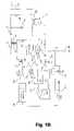
- FIG. 1is a schematic diagram of a power converter in accordance with an embodiment of the present invention.
- FIG. 1Bis a schematic diagram of a power converter in accordance with an alternative embodiment of the present invention.
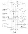
- FIG. 2is a waveform diagram depicting signals within the power converters of FIGS. 1 and 1B .
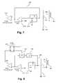
- FIG. 3is a schematic diagram of a power converter in accordance with another embodiment of the present invention.
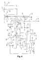
- FIG. 4is a schematic diagram of a power converter in accordance with yet another embodiment of the present invention.
- FIG. 5is a waveform diagram depicting signals within the power converters of FIGS. 3 and 4 .
- FIG. 6is a schematic diagram of a power converter in accordance with yet another embodiment of the present invention.
- FIG. 7is a schematic diagram depicting details of an ESR-compensated control circuit in accordance with an embodiment of the present invention.
- FIG. 8is a schematic diagram depicting details of an ESR-compensated control circuit in accordance with another embodiment of the present invention.
- the present inventionprovides novel circuits and methods for controlling a power supply output voltage using predictive sensing of magnetic flux. As a result, the line and load regulation of a switching power converter can be improved by incorporating one or more aspects of the present invention.
- the present inventionincludes, alone or in combination, a unique sampling error amplifier with zero magnetization detection circuitry and unique pulse width modulator control circuits.
- FIG. 1shows a simplified block diagram of a first embodiment of the present invention.
- the switching configuration shownis a flyback converter topology. It includes a transformer 101 with a primary winding 141 , a secondary winding 142 , an auxiliary winding 103 , a secondary rectifier 107 and a smoothing capacitor 108 .
- a resistor 109represents an output load of the flyback converter.
- a capacitor 146represents total parasitic capacitance present at an input terminal of primary winding 141 , including the output capacitance of the switch 102 , inter-winding capacitance of the transformer 101 and other parasitics. Capacitance may be added in the form of additional discrete capacitors if needed in particular implementations for lowering the frequency of the post-conduction resonance condition.
- the power converter of FIG. 3also includes an input terminal 147 , a supply voltage terminal 143 which is a voltage derived from auxiliary winding 103 by means of a rectifier 113 and a smoothing capacitor 112 , a feedback terminal 144 , and a ground terminal 145 .
- Voltage VIN at the input terminal 147is an unregulated or poorly regulated DC voltage, such as one generated by the input rectifier circuitry of an offline power supply.
- the power converteralso includes a power switch 102 for switching current through the primary winding 141 from input terminal 147 to ground terminal 145 , a sample-and-hold circuit 124 connected to feedback terminal 144 via a resistive voltage divider formed by resistors 110 and 111 , an error amplifier circuit 123 having one of a pair of differential inputs connected to an output of sample-and-hold circuit 124 and having another differential input connected to a reference voltage REF, a pulse width modulator circuit 105 that generates a pulsed signal having a duty ratio as a function of an output signal of error amplifier circuit 123 , a gate driver 106 for controlling on and off states of power switch 102 in accordance with the output of the pulse width modulator circuit 105 , an integrator circuit 128 having an input connected to feedback terminal 144 and a reset input, a differentiator circuit 127 having an input connected to feedback terminal 144 , a zero-derivative detect comparator 126 having a small hysteresis and having one of a pair or
- auxiliary winding 103being provided as a transformer winding
- the feedback signalis provided by auxiliary winding 103 of an output filter inductor 145 .
- a free-wheeling diode 199is added to the circuit to return energy from a power winding 198 of output filter inductor 145 , to capacitor 108 and load 109 .
- switch 102When switch 102 is enabled, a secondary voltage of positive polarity appears across winding 142 equal to input voltage VIN divided by turn ratio between windings 141 and 142 .
- Diode 107conducts, coupling the power winding of inductor 198 between winding 142 and filter capacitor 108 . Energy is thereby stored in inductor 198 .
- switch 102When switch 102 is disabled, diode 107 becomes reverse biased, and diode 199 conducts, returning energy stored in inductor 198 to output filter capacitor 108 and load 109 .
- inductor 198When the magnetic energy stored in inductor 198 fully depleted, inductor 198 enters post-conduction resonance (similar to that of transformer 101 in the circuit of FIG. 1 ). Therefore, auxiliary winding 103 provides similar waveforms as the circuit of FIG. 1 and provides a similar voltage feedback signal that are used by the control circuit of the present invention.
- the feedback voltageis proportional to the difference between VIN divided by the turn ratio between windings 141 and 142 and the output voltage across capacitor 108 .
- the feedback terminal 144 voltagecauses a linear increase in the output voltage 202 of integrator 128 .
- the duration of the on-time of the power switch 102is determined by the magnitude of the error signal at the output of error amplifier 123 .
- the period of the post-conduction resonanceis a function of the inductance of primary winding 141 and parasitic capacitance 146 (or the parasitic capacitance as reflected at the power winding of filter inductor 198 in the circuit of FIG. 1B ).
- Differentiator circuit 127continuously generates an output corresponding to the derivative of voltage 201 at feedback terminal 144 .
- the output of differentiator 127is compared to a small reference voltage 131 by comparator 126 , in order to detect a zero-derivative condition at feedback terminal 144 .
- Comparator 126provides a hysteresis to eliminate its false tripping due to noise at the feedback terminal 144 .
- Output voltage 202 of integrator 128is sampled at time T 2 , when comparator 126 detects the zero-derivative condition at feedback terminal 144 (positive edge of comparator 126 output 204 ).
- Blanking circuit 134disables the output of comparator 126 , only enabling sample-and-hold circuit 129 during post-conduction resonance.
- the blanking signalis represented by a waveform 205 and the output of blanking circuit 134 is represented by a waveform 206 .
- samplingis enabled at time T 1 when the voltage at the feedback terminal 144 reaches substantially zero.
- the voltage at the output of sample-and-hold circuit 129is offset by a small voltage 130 ( ⁇ V of FIG. 2 ).
- Comparator 125triggers sample-and-hold circuit 124 , which samples the feedback voltage at the output of the resistive divider formed by resistors 110 , 111 at time Tfb.
- Waveform 207shows the timing of feedback voltage sampling by sample-and-hold circuit 124 .
- the sampled feedback voltageis compared to reference voltage REF by error amplifier 123 , which outputs an error signal that controls pulse width modulator circuit 105 .
- integrator 128Every switching cycle, the output of integrator 128 is reset to a constant voltage level Vreset by a reset pulse 203 in order to remove integration errors. It is convenient to reset integrator 128 following time T 2 . However, in general, integrator 128 can be reset at any time with the exceptions of times Tfb and T 1 which are sampling times.
- the output of integrator 128represents a voltage analog of the magnetization current in the transformer 101 (and magnetization current of filter inductor 198 in the circuit of FIG. 1B ).
- Voltage offset ⁇ Vsets a constant small from the actual secondary winding 142 zero-current point, and this a small offset in sampling time Tfb, at which the voltage at feedback terminal 144 is sampled.
- a method and apparatus in accordance with an alternative embodiment of the present inventionare included in traditional peak current mode controlled pulse width modulator circuit to form a circuit as depicted in FIG. 3 , wherein like reference designators are used to indicate like elements between the circuit of FIGS. 1 and 3 . Only differences between the circuits of FIGS. 1 and 3 will be described below.
- Pulse width modulator circuitincludes a pulse width modulator comparator 132 and a latch circuit 133 .
- comparator 132resets latch 133 and turns off power switch 102 .
- Latch 133is set with a fixed frequency Clock signal at the beginning of the next switching cycle, initiating the next turn-on of the switch 102 .
- FIG. 4depicts a switching power converter in accordance with yet another embodiment of the present invention that is similar to the circuit of FIG. 3 , but is set up to operate in critically discontinuous (boundary) conduction mode of flyback transformer 101 .
- the circuit of FIG. 4is free running. A free running operating mode is provided by connecting the output of blanking circuit 134 to the “S” (set) input of latch 133 . Operation of the circuit of FIG. 4 is illustrated in the waveform diagrams of FIG. 5 . Referring to FIGS.
- waveform 301represents the voltage at feedback terminal 144
- waveform 302shows the output voltage of the integrator circuit
- waveform 303shows the Reset timing of the integrator 128 .
- the output of zero-derivative detect comparator 126is depicted by waveform 304 .
- Waveforms 305 , 306 and 307show the blanking 134 , the integrator sample-and-hold 129 and feedback sample-and-hold 124 timings, respectively. Operation of the power converter circuit of FIG. 4 is similar to the one of FIG. 3 , except that latch circuit 133 is reset by the output of blanking circuit 134 .
- the resetoccurs when comparator 126 detects a zero-derivative condition in feedback terminal 144 output voltage 301 during post-conduction resonance. Therefore, power switch 102 is turned on after one half period of the post conduction resonance at the lowest possible voltage across switch 102 .
- the above-described “valley” switching techniqueminimizes power losses in switch 102 due to discharging of parasitic capacitance 146 .
- the transformer 101is operated in the boundary conduction mode, since the next switching cycle always starts immediately after the entire magnetization energy is transferred to the power supply output. Operating the transformer 101 in the critically discontinuous conduction mode reduces power loss and improves the efficiency of the switching power converter of FIG. 4 .
- Indirect current sensing by synthesizing a voltage corresponding to magnetization current(as performed in the control circuits of FIGS. 3 , 4 and 6 ) enables construction of single stage power factor corrected (SS-PFC) switching power converters.
- SS-PFCsingle stage power factor corrected
- FIG. 6One example of such an SS-PFC switching power converter is shown in FIG. 6 .
- the control circuitis identical to that of FIG. 4 , only the switching and input circuits differ. Common reference designators are used in FIGS. 4 and 6 and only differences will be described below.
- the power converter of FIG. 6includes a power transformer 101 with two primary windings 141 with blocking diodes 50 and 51 , two bulk energy storage capacitors 135 with a series connected diode 52 , in addition to all other elements of the power converter of FIG. 4 .
- the input voltage VINis a full wave rectified input AC line voltage.
- the voltage VINis applied across a boost inductor 136 via a diode 137 , causing a linear increase in the current through inductor 136 .
- a substantially constant voltage from bulk energy storage capacitors 135is applied across primary windings 141 through forward-biased diodes 50 and 51 , causing transformer 101 to store magnetization energy.
- Diode 52is reversed-biased during this period.
- power switch 102conducts a superposition of magnetization currents of the transformer 101 and boost inductor 136 .
- transformer 101transfers its stored energy via diode 107 to capacitor 108 and load 109 .
- boost inductor 136transfers its energy to bulk energy storage capacitors 135 via primary windings 141 and forward biased diode 52 .
- diodes 50 and 51are reverse-biased.
- Boost inductor 136is designed to operate in discontinuous conduction mode. Therefore, its magnetization current is proportional to the input voltage VIN, inherently providing good power factor performance, as the average input impedance has little or no reactive component. Diode 137 ensures discontinuous conduction of boost inductor 136 by blocking reverse current.
- a peak current mode control schemethat maintains peak current in power switch 102 in proportion to the output of voltage error amplifier 123 , is not generally desirable in the power converter of FIG. 6 . Since the current through power switch 102 is a superposition of the currents in boost inductor winding 136 and transformer primary windings 141 , keeping the power switch current proportional to the voltage error signal tends to distort the input current waveform.
- the voltage error signalis made independent of the current in boost inductor 136 , while the voltage error signal set proportional to the magnetization current in the transformer 101 . Therefore, the switching power converter of FIG. 6 inherently provides good power factor performance.
- the above-described control circuiteliminates the need for direct current sensing. The method of the control circuit described above also provides an inherent output over-current protection when the voltage error signal is limited.
- FIG. 7depicts a compensation resistor 138 connected between the output of voltage error amplifier 123 and the output of the resistive divider formed by resistors 110 , 111 , which can be added to the switching power converters of FIGS. 4 and 6 to cancel the above-described regulation error, since the voltage at the output of error amplifier 123 is representative of the power converter output current Io.
- the circuit of FIG. 7compensates for output voltage error due to ESR of capacitor 108 for a given duty ratio of power switch 102 .
- the value of resistor 138is selected in inverse proportion to (1 ⁇ D), where D is the duty ratio of the power switch 102 .
- a circuit as depicted in FIG. 8may be implemented.
- the circuit of FIG. 8includes a compensation resistor 138 , a low pass filter 139 and a chopper circuit 140 .
- chopper circuit 140corrects the compensation current of resistor 138 by factor of (1 ⁇ D), chopping the output voltage of error amplifier 123 using the inverting output signal of the pulse width modulator latch 133 .
- the switching component of the compensation signalis filtered using low pass filter 139 .
- the present inventionintroduces a new method and apparatus for controlling output voltage of magnetically coupled isolated switching power converters that eliminate a requirement for opto-feedback, current sense resistors and/or separate feedback transformers by selective sensing of magnetic flux. Further, the present invention provides high switching power converter efficiency by minimizing switching losses. The present invention is particularly useful in single-stage single-switch power factor corrected AC/DC converters due to the indirect current sensing technique of the present invention, but may be applied to other applications where the advantages of the present invention are desirable.
- the circuits depicted and claimed hereincan alternatively derive their flux measurement from any winding of a power transformer or output filter inductor. Further, the measurement techniques may be applied to non-coupled designs where it may be desirable to detect the flux in an inductor that is discontinuously switched between an energizing state and a load transfer state.
Landscapes
- Engineering & Computer Science (AREA)
- Power Engineering (AREA)
- Dc-Dc Converters (AREA)
Abstract
Description
Claims (31)
Priority Applications (1)
| Application Number | Priority Date | Filing Date | Title |
|---|---|---|---|
| US10/838,820US6958920B2 (en) | 2003-10-02 | 2004-05-04 | Switching power converter and method of controlling output voltage thereof using predictive sensing of magnetic flux |
Applications Claiming Priority (3)
| Application Number | Priority Date | Filing Date | Title |
|---|---|---|---|
| US10/677,439US20040264216A1 (en) | 2003-06-25 | 2003-10-02 | Switching power converter and method of controlling output voltage thereof using predictive sensing of magnetic flux |
| US53451504P | 2004-01-06 | 2004-01-06 | |
| US10/838,820US6958920B2 (en) | 2003-10-02 | 2004-05-04 | Switching power converter and method of controlling output voltage thereof using predictive sensing of magnetic flux |
Related Parent Applications (1)
| Application Number | Title | Priority Date | Filing Date |
|---|---|---|---|
| US10/677,439Continuation-In-PartUS20040264216A1 (en) | 2003-06-25 | 2003-10-02 | Switching power converter and method of controlling output voltage thereof using predictive sensing of magnetic flux |
Publications (2)
| Publication Number | Publication Date |
|---|---|
| US20050073862A1 US20050073862A1 (en) | 2005-04-07 |
| US6958920B2true US6958920B2 (en) | 2005-10-25 |
Family
ID=34396625
Family Applications (1)
| Application Number | Title | Priority Date | Filing Date |
|---|---|---|---|
| US10/838,820Expired - LifetimeUS6958920B2 (en) | 2003-10-02 | 2004-05-04 | Switching power converter and method of controlling output voltage thereof using predictive sensing of magnetic flux |
Country Status (1)
| Country | Link |
|---|---|
| US (1) | US6958920B2 (en) |
Cited By (127)
| Publication number | Priority date | Publication date | Assignee | Title |
|---|---|---|---|---|
| US20050253562A1 (en)* | 2004-05-06 | 2005-11-17 | Logsdon Timothy D | Power supply system method of use |
| US20060018136A1 (en)* | 2004-07-20 | 2006-01-26 | Matsushita Electric Industrial Co., Ltd. | Switching power supply unit and semiconductor device for switching power supply |
| US20060083032A1 (en)* | 2004-10-15 | 2006-04-20 | Dell Products, L.P. | Primary side voltage sense for AC/DC power supplies |
| US20060250824A1 (en)* | 2005-05-09 | 2006-11-09 | Wekhande Shashank S | Capacitor charging methods and apparatus |
| US20060261889A1 (en)* | 2005-05-19 | 2006-11-23 | Giovannotto Roberto M | System and method for employing variable magnetic flux bias in an amplifier |
| US20060284567A1 (en)* | 2005-06-16 | 2006-12-21 | Active-Semi International Inc. | Primary side constant output voltage controller |
| US20060285365A1 (en)* | 2005-06-16 | 2006-12-21 | Active Semiconductors International Inc. | Primary side constant output current controller |
| US20070019445A1 (en)* | 2005-07-21 | 2007-01-25 | Matthew Blaha | Switch with fully isolated power sourcing equipment control |
| US20070063682A1 (en)* | 2005-09-19 | 2007-03-22 | Dagher Elias H | Switched mode power converter |
| US20070103943A1 (en)* | 2005-05-09 | 2007-05-10 | Vijay Mangtani | Capacitor charging methods and apparatus |
| US7248487B1 (en) | 2006-06-01 | 2007-07-24 | Cambridge Semiconductor Limited | Switch mode power supply controllers |
| US20070263415A1 (en)* | 2006-02-14 | 2007-11-15 | Arian Jansen | Two terminals quasi resonant tank circuit |
| WO2007135452A1 (en)* | 2006-05-23 | 2007-11-29 | Cambridge Semiconductor Limited | Switch mode power supply controllers |
| US20070274106A1 (en)* | 2006-05-23 | 2007-11-29 | David Robert Coulson | Switch mode power supply controllers |
| US20070274107A1 (en)* | 2006-05-23 | 2007-11-29 | Garner David M | Switch mode power supply controllers |
| US20080007977A1 (en)* | 2006-07-07 | 2008-01-10 | Johan Piper | Switch mode power supply systems |
| US20080007982A1 (en)* | 2006-07-07 | 2008-01-10 | Johan Piper | Switch mode power supply systems |
| US20080037294A1 (en)* | 2006-05-23 | 2008-02-14 | Cambridge Semiconductor Limited | Switch mode power supply controllers |
| US20080074095A1 (en)* | 2006-09-25 | 2008-03-27 | Telefus Mark D | Bi-directional regulator |
| US20080080105A1 (en)* | 2006-09-29 | 2008-04-03 | Agere Systems Inc. | Isolated switched maintain power signature (mps) and fault monitoring for power over ethernet |
| US20080094047A1 (en)* | 2006-01-06 | 2008-04-24 | Active-Semi International, Inc. | Primary side constant output voltage controller |
| US20080123377A1 (en)* | 2006-11-24 | 2008-05-29 | Tzu-Chen Lin | Circuit and method for predicting a valley timing for a voltage across a switching device |
| US20080224629A1 (en)* | 2007-03-12 | 2008-09-18 | Melanson John L | Lighting system with power factor correction control data determined from a phase modulated signal |
| US20080224631A1 (en)* | 2007-03-12 | 2008-09-18 | Melanson John L | Color variations in a dimmable lighting device with stable color temperature light sources |
| US20080240789A1 (en)* | 2007-03-28 | 2008-10-02 | Fuji Xerox Co., Ltd. | Rotator for powder conveyance and toner cartridge |
| US20080238379A1 (en)* | 2007-03-29 | 2008-10-02 | Mark Telefus | Pulse frequency to voltage conversion |
| US20080238600A1 (en)* | 2007-03-29 | 2008-10-02 | Olson Bruce D | Method of producing a multi-turn coil from folded flexible circuitry |
| US20080238389A1 (en)* | 2007-03-29 | 2008-10-02 | Mark Telefus | Primary only control quasi resonant convertor |
| US20080239760A1 (en)* | 2007-03-29 | 2008-10-02 | Mark Telefus | Primary only constant voltage/constant current (CVCC) control in quasi resonant convertor |
| US20080259654A1 (en)* | 2007-04-23 | 2008-10-23 | Active-Semi International, Inc. | Compensating for cord resistance to maintain constant voltage at the end of a power converter cord |
| US20080259650A1 (en)* | 2007-04-23 | 2008-10-23 | Active-Semi International, Inc. | Changing switching frequency of a primary side power converter to compensate for inductance variation |
| US20080259656A1 (en)* | 2007-04-23 | 2008-10-23 | Active-Semi International, Inc. | Regulating output current from a primary side power converter by clamping an error signal |
| US20080272756A1 (en)* | 2007-05-02 | 2008-11-06 | Melanson John L | Power factor correction controller with digital fir filter output voltage sampling |
| US20080310191A1 (en)* | 2007-06-12 | 2008-12-18 | Bcd Semiconductor Manufacturing Limited | Method and system for pulse frequency modulated switching mode power supplies |
| US20090034301A1 (en)* | 2007-07-30 | 2009-02-05 | Chou Chung Fu | Switching Power Converter Controlled by a Winding Voltage Sampler |
| US20090067201A1 (en)* | 2007-09-06 | 2009-03-12 | Jun Cai | Isolated Switched-mode Power Supply With Output Regulation From Primary Side |
| US20090079528A1 (en)* | 2007-09-25 | 2009-03-26 | Flextronics Ap, Llc | Thermally enhanced magnetic transformer |
| US7551460B2 (en) | 2006-05-23 | 2009-06-23 | Cambridge Semiconductor Limited | Switch mode power supply controllers |
| US20090168465A1 (en)* | 2007-12-29 | 2009-07-02 | Innocom Technology (Shenzhen) Co., Ltd., Innolux Display Corp. | Power supply circuit with protecting circuit |
| US7558093B1 (en)* | 2005-11-10 | 2009-07-07 | Iwatt Inc. | Power converter with emulated peak current mode control |
| US20090191837A1 (en)* | 2008-01-30 | 2009-07-30 | Kartik Nanda | Delta Sigma Modulator with Unavailable Output Values |
| US20090189579A1 (en)* | 2008-01-30 | 2009-07-30 | Melanson John L | Switch state controller with a sense current generated operating voltage |
| US20090190384A1 (en)* | 2008-01-30 | 2009-07-30 | Cirrus Logic, Inc. | Powering a power supply integrated circuit with sense current |
| US20090279333A1 (en)* | 2008-05-06 | 2009-11-12 | Bcd Semiconductor Manufacturing Limited | Method and apparatus for reducing standby power of switching mode power supplies |
| US20090290384A1 (en)* | 2008-05-21 | 2009-11-26 | Flextronics, Ap, Llc | High power factor isolated buck-type power factor correction converter |
| US20090290385A1 (en)* | 2008-05-21 | 2009-11-26 | Flextronics Ap, Llc | Resonant power factor correction converter |
| US20090295348A1 (en)* | 2008-05-30 | 2009-12-03 | Active-Semi, Inc. | Constant current and voltage controller in a three-pin package with dual-use power pin |
| US20090295349A1 (en)* | 2008-05-30 | 2009-12-03 | Active-Semi, Inc. | Constant current and voltage controller in a three-pin package with dual-use switch pin |
| US20090295531A1 (en)* | 2008-05-28 | 2009-12-03 | Arturo Silva | Optimized litz wire |
| US20090310384A1 (en)* | 2008-06-12 | 2009-12-17 | Bahman Sharifipour | AC-DC input adapter |
| US7643320B2 (en) | 2007-03-28 | 2010-01-05 | Agere Systems Inc. | Isolated resistive signature detection for powered devices |
| US7643315B2 (en) | 2006-08-22 | 2010-01-05 | Agere Systems, Inc. | Programmable feedback voltage pulse sampling for switched power supplies |
| US20100067270A1 (en)* | 2008-09-15 | 2010-03-18 | Power Integrations, Inc. | Method and apparatus to reduce line current harmonics from a power supply |
| US20100079181A1 (en)* | 2008-09-29 | 2010-04-01 | Infineon Technologies Austria Ag | Sample-point adjustment in a switching converter |
| US20100079125A1 (en)* | 2008-07-25 | 2010-04-01 | Melanson John L | Current sensing in a switching power converter |
| US20100118573A1 (en)* | 2008-11-07 | 2010-05-13 | Power Integrations, Inc. | Method and apparatus to increase efficiency in a power factor correction circuit |
| US20100118571A1 (en)* | 2008-11-07 | 2010-05-13 | Power Integrations, Inc. | Method and apparatus to control a power factor correction circuit |
| US20100127737A1 (en)* | 2008-11-21 | 2010-05-27 | Flextronics Ap, Llc | Variable PFC and grid-tied bus voltage control |
| US20100148677A1 (en)* | 2008-12-12 | 2010-06-17 | Melanson John L | Time division light output sensing and brightness adjustment for different spectra of light emitting diodes |
| US20100164631A1 (en)* | 2008-12-31 | 2010-07-01 | Cirrus Logic, Inc. | Electronic system having common mode voltage range enhancement |
| US20100164406A1 (en)* | 2008-07-25 | 2010-07-01 | Kost Michael A | Switching power converter control with triac-based leading edge dimmer compatibility |
| US7759881B1 (en) | 2008-03-31 | 2010-07-20 | Cirrus Logic, Inc. | LED lighting system with a multiple mode current control dimming strategy |
| US20100218003A1 (en)* | 2005-06-16 | 2010-08-26 | Agere Systems Inc. | Transformerless power over ethernet system |
| US7804697B2 (en) | 2007-12-11 | 2010-09-28 | Cirrus Logic, Inc. | History-independent noise-immune modulated transformer-coupled gate control signaling method and apparatus |
| US20100246216A1 (en)* | 2006-05-23 | 2010-09-30 | Cambridge Semiconductor Limited | Switch mode power supply controllers |
| US20100277072A1 (en)* | 2009-04-30 | 2010-11-04 | Draper William A | Calibration Of Lamps |
| US20100289466A1 (en)* | 2009-05-15 | 2010-11-18 | Flextronics Ap, Llc | Closed loop negative feedback system with low frequency modulated gain |
| US20100328976A1 (en)* | 2009-06-30 | 2010-12-30 | Melanson John L | Cascode configured switching using at least one low breakdown voltage internal, integrated circuit switch to control at least one high breakdown voltage external switch |
| US20110006746A1 (en)* | 2009-07-09 | 2011-01-13 | Richtek Technology Corp. | Soft-start circuit and method for a switching regulator |
| US20110025286A1 (en)* | 2007-10-17 | 2011-02-03 | Power Systems Technologies Gmbh | Control Circuit For a Primary Controlled Switched Mode Power Supply with Improved Accuracy of the Voltage Control and Primary Controlled Switched Mode Power Supply |
| US20110074302A1 (en)* | 2009-09-30 | 2011-03-31 | Draper William A | Phase Control Dimming Compatible Lighting Systems |
| US20110157922A1 (en)* | 2009-12-30 | 2011-06-30 | Pavel Konecny | Primary side sensing for isolated fly-back converters |
| US7978489B1 (en) | 2007-08-03 | 2011-07-12 | Flextronics Ap, Llc | Integrated power converters |
| US20110170325A1 (en)* | 2010-01-14 | 2011-07-14 | Flextronics Ap, Llc | Line switcher for power converters |
| US20110182088A1 (en)* | 2008-11-14 | 2011-07-28 | Petr Lidak | Quasi-resonant power supply controller and method therefor |
| US7996166B2 (en)* | 2007-03-26 | 2011-08-09 | Agere Systems Inc. | Isolated capacitive signature detection for powered devices |
| US20110203840A1 (en)* | 2010-02-23 | 2011-08-25 | Flextronics Ap, Llc | Test point design for a high speed bus |
| US8008902B2 (en) | 2008-06-25 | 2011-08-30 | Cirrus Logic, Inc. | Hysteretic buck converter having dynamic thresholds |
| US8008898B2 (en) | 2008-01-30 | 2011-08-30 | Cirrus Logic, Inc. | Switching regulator with boosted auxiliary winding supply |
| US20110210674A1 (en)* | 2007-08-24 | 2011-09-01 | Cirrus Logic, Inc. | Multi-LED Control |
| US8014176B2 (en) | 2008-07-25 | 2011-09-06 | Cirrus Logic, Inc. | Resonant switching power converter with burst mode transition shaping |
| US8018171B1 (en) | 2007-03-12 | 2011-09-13 | Cirrus Logic, Inc. | Multi-function duty cycle modifier |
| KR101080742B1 (en) | 2009-12-29 | 2011-11-07 | 한국항공우주연구원 | Power Supply |
| US8076920B1 (en) | 2007-03-12 | 2011-12-13 | Cirrus Logic, Inc. | Switching power converter and control system |
| US20120008345A1 (en)* | 2010-07-07 | 2012-01-12 | Richtek Technology Corp. | Apparatus and method for output voltage calibration of a primary feedback flyback power module |
| US8102127B2 (en) | 2007-06-24 | 2012-01-24 | Cirrus Logic, Inc. | Hybrid gas discharge lamp-LED lighting system |
| US20120062194A1 (en)* | 2010-09-13 | 2012-03-15 | Immense Advance Technology Corp. | High side controller capable of sensing input voltage and ouput voltage of a power conversion circuit |
| US8179110B2 (en) | 2008-09-30 | 2012-05-15 | Cirrus Logic Inc. | Adjustable constant current source with continuous conduction mode (“CCM”) and discontinuous conduction mode (“DCM”) operation |
| US8198874B2 (en) | 2009-06-30 | 2012-06-12 | Cirrus Logic, Inc. | Switching power converter with current sensing transformer auxiliary power supply |
| US8212493B2 (en) | 2009-06-30 | 2012-07-03 | Cirrus Logic, Inc. | Low energy transfer mode for auxiliary power supply operation in a cascaded switching power converter |
| US8222872B1 (en) | 2008-09-30 | 2012-07-17 | Cirrus Logic, Inc. | Switching power converter with selectable mode auxiliary power supply |
| US8279646B1 (en) | 2007-12-14 | 2012-10-02 | Flextronics Ap, Llc | Coordinated power sequencing to limit inrush currents and ensure optimum filtering |
| US8288954B2 (en) | 2008-12-07 | 2012-10-16 | Cirrus Logic, Inc. | Primary-side based control of secondary-side current for a transformer |
| US20120300506A1 (en)* | 2011-05-25 | 2012-11-29 | Min-Woo Lee | Power supply device and driving method thereof |
| US20120320635A1 (en)* | 2011-06-14 | 2012-12-20 | Sync Power Corp. | Maximize efficiency method for resonant converter with self-adjusting switching points |
| US8362707B2 (en) | 2008-12-12 | 2013-01-29 | Cirrus Logic, Inc. | Light emitting diode based lighting system with time division ambient light feedback response |
| US20130083566A1 (en)* | 2011-09-30 | 2013-04-04 | Power Integrations, Inc. | Multi-stage sampling circuit for a power converter controller |
| CN101647183B (en)* | 2007-03-29 | 2013-04-24 | 弗莱克斯电子有限责任公司 | A kind of power equipment and its adjustment method |
| US20130147452A1 (en)* | 2011-12-07 | 2013-06-13 | System General Corporation | Switching current synthesis circuit for power converter |
| US8487546B2 (en) | 2008-08-29 | 2013-07-16 | Cirrus Logic, Inc. | LED lighting system with accurate current control |
| US8488340B2 (en) | 2010-08-27 | 2013-07-16 | Flextronics Ap, Llc | Power converter with boost-buck-buck configuration utilizing an intermediate power regulating circuit |
| US8536794B2 (en) | 2007-03-12 | 2013-09-17 | Cirrus Logic, Inc. | Lighting system with lighting dimmer output mapping |
| US20130343095A1 (en)* | 2012-06-26 | 2013-12-26 | Bcd Semiconductor Manufacturing Co., Ltd. | Circuits and methods for increasing power factor of switch mode power supply |
| US20140043081A1 (en)* | 2012-08-08 | 2014-02-13 | Leadtrend Technology Corp. | Sample-and-hold circuit for generating a variable sample delay time of a transformer and method thereof |
| US8654483B2 (en) | 2009-11-09 | 2014-02-18 | Cirrus Logic, Inc. | Power system having voltage-based monitoring for over current protection |
| CN103675425A (en)* | 2012-09-18 | 2014-03-26 | 张翌 | Self-adaptive quasi-resonance valley detection circuit of flyback switching power supply |
| US8729811B2 (en) | 2010-07-30 | 2014-05-20 | Cirrus Logic, Inc. | Dimming multiple lighting devices by alternating energy transfer from a magnetic storage element |
| US8823289B2 (en) | 2011-03-24 | 2014-09-02 | Cirrus Logic, Inc. | Color coordination of electronic light sources with dimming and temperature responsiveness |
| US20140268924A1 (en)* | 2013-03-13 | 2014-09-18 | Richtek Technology Corporation | Control circuit for flyback power converter and calibration method thereof |
| US8912734B2 (en) | 2011-03-24 | 2014-12-16 | Cirrus Logic, Inc. | Color mixing of electronic light sources with correlation between phase-cut dimmer angle and predetermined black body radiation function |
| US8964413B2 (en) | 2010-04-22 | 2015-02-24 | Flextronics Ap, Llc | Two stage resonant converter enabling soft-switching in an isolated stage |
| US8963535B1 (en) | 2009-06-30 | 2015-02-24 | Cirrus Logic, Inc. | Switch controlled current sensing using a hall effect sensor |
| US9083254B1 (en)* | 2006-11-20 | 2015-07-14 | Picor Corporation | Primary side sampled feedback control in power converters |
| US9093911B2 (en) | 2013-03-15 | 2015-07-28 | Flextronics Ap, Llc | Switching mode power converter using coded signal control |
| US9117991B1 (en) | 2012-02-10 | 2015-08-25 | Flextronics Ap, Llc | Use of flexible circuits incorporating a heat spreading layer and the rigidizing specific areas within such a construction by creating stiffening structures within said circuits by either folding, bending, forming or combinations thereof |
| DE102014104269B4 (en)* | 2013-04-05 | 2015-10-22 | Infineon Technologies Austria Ag | Switching power supply, which contains a flyback converter with primary-side control |
| US9173261B2 (en) | 2010-07-30 | 2015-10-27 | Wesley L. Mokry | Secondary-side alternating energy transfer control with inverted reference and LED-derived power supply |
| US9204503B1 (en) | 2012-07-03 | 2015-12-01 | Philips International, B.V. | Systems and methods for dimming multiple lighting devices by alternating transfer from a magnetic storage element |
| US9515545B2 (en) | 2014-02-14 | 2016-12-06 | Infineon Technologies Austria Ag | Power conversion with external parameter detection |
| US9549463B1 (en) | 2014-05-16 | 2017-01-17 | Multek Technologies, Ltd. | Rigid to flexible PC transition |
| US20170077820A1 (en)* | 2015-09-11 | 2017-03-16 | Leadtrend Technology Corp. | Sample-and-hold circuit for generating a variable sample signal of a power converter and method thereof |
| USRE46369E1 (en) | 2008-06-10 | 2017-04-18 | Bcd Semiconductor Manufacturing Limited | Control circuits and methods for switching mode power supplies |
| US9661743B1 (en) | 2013-12-09 | 2017-05-23 | Multek Technologies, Ltd. | Flexible circuit board and method of fabricating |
| US20170187295A1 (en)* | 2014-04-25 | 2017-06-29 | Silergy Semiconductor Technology (Hangzhou) Ltd | Control circuit, control method and primary-controlled flyback converter using the same |
| US9723713B1 (en) | 2014-05-16 | 2017-08-01 | Multek Technologies, Ltd. | Flexible printed circuit board hinge |
| US9862561B2 (en) | 2012-12-03 | 2018-01-09 | Flextronics Ap, Llc | Driving board folding machine and method of using a driving board folding machine to fold a flexible circuit |
| US10154583B1 (en) | 2015-03-27 | 2018-12-11 | Flex Ltd | Mechanical strain reduction on flexible and rigid-flexible circuits |
Families Citing this family (34)
| Publication number | Priority date | Publication date | Assignee | Title |
|---|---|---|---|---|
| US9153960B2 (en) | 2004-01-15 | 2015-10-06 | Comarco Wireless Technologies, Inc. | Power supply equipment utilizing interchangeable tips to provide power and a data signal to electronic devices |
| WO2007041894A1 (en)* | 2005-10-09 | 2007-04-19 | System General Corp. | Switching control circuit for primary-side controlled power converters |
| JP4733186B2 (en)* | 2005-10-09 | 2011-07-27 | システム ジェネラル コーポレーション | Switching control circuit with variable switching frequency for a power converter with controlled primary side |
| KR20080066937A (en)* | 2005-11-07 | 2008-07-17 | 로슨 랩스, 인크. | Power-Conversion Regulator with Power Feedback Loop |
| DE102005055160B4 (en)* | 2005-11-18 | 2011-12-29 | Power Systems Technologies Gmbh | Control circuit for current and voltage control in a switching power supply |
| GB2438462A (en)* | 2006-05-23 | 2007-11-28 | Cambridge Semiconductor Ltd | Regulating the output of a switch mode power supply |
| WO2007135454A1 (en)* | 2006-05-23 | 2007-11-29 | Cambridge Semiconductor Limited | Switch mode power supply controllers |
| EP2115863A1 (en)* | 2007-02-27 | 2009-11-11 | Nxp B.V. | Load current detection in electrical power converters |
| ITTO20070860A1 (en)* | 2007-11-29 | 2009-05-30 | St Microelectronics Srl | CIRCUIT AND ITS SELF-POWER SUPPLY METHOD FOR A VOLTAGE CONVERTER |
| ITTO20070862A1 (en)* | 2007-11-29 | 2009-05-30 | St Microelectronics Srl | VOLTAGE ISOLATED CONVERTER WITH FEEDBACK TO THE PRIMARY AND PASSIVE SNUBBER NETWORK, AND RELATIVE CONTROL METHOD |
| ITTO20070859A1 (en)* | 2007-11-29 | 2009-05-30 | St Microelectronics Srl | VOLTAGE ISOLATED CONVERTER WITH FEEDBACK TO THE PRIMARY, AND RELATIVE OUTPUT TENSION CONTROL METHOD |
| CN102090145B (en) | 2008-07-09 | 2013-09-25 | Nxp股份有限公司 | Switched mode power converter and method of operation thereof |
| WO2010015999A1 (en)* | 2008-08-06 | 2010-02-11 | Nxp B.V. | Converter with controlled output current |
| WO2010020909A1 (en)* | 2008-08-21 | 2010-02-25 | Nxp B.V. | Load current detection in electrical power converters |
| EP2330727B1 (en) | 2009-11-30 | 2017-08-02 | Nxp B.V. | Method of controlling a PFC stage operating in boundary conduction mode |
| US20110149613A1 (en)* | 2009-12-23 | 2011-06-23 | Comarco Wireless Technologies, Inc. | Flyback converter utilizing boost inductor between ac source and bridge rectifier |
| CN102332826B (en)* | 2010-07-13 | 2013-11-13 | 昂宝电子(上海)有限公司 | System and method for sensing and adjustment of primary side of flyback power converter |
| TWI406486B (en)* | 2010-08-10 | 2013-08-21 | 昂寶電子(上海)有限公司 | Systems and methods of primary-side sensing and regulation for flyback power converter with high stability |
| EP2424098A1 (en)* | 2010-08-27 | 2012-02-29 | Nxp B.V. | Primary side sensing of an isolated converter |
| US8854319B1 (en) | 2011-01-07 | 2014-10-07 | Maxim Integrated Products, Inc. | Method and apparatus for generating piezoelectric transducer excitation waveforms using a boost converter |
| EP2515426B1 (en)* | 2011-04-20 | 2019-06-12 | Nxp B.V. | A switching circuit |
| GB2490542A (en)* | 2011-05-06 | 2012-11-07 | Texas Instr Cork Ltd | Sensing arrangement for estimating the output voltage of an isolated flyback converter |
| EP2573921B1 (en) | 2011-09-22 | 2020-05-06 | Nxp B.V. | A controller for a switched mode power supply |
| US9419527B2 (en)* | 2012-03-07 | 2016-08-16 | Dialog Semiconductor Inc. | Regulation for power supply mode transition to low-load operation |
| US9007052B2 (en)* | 2012-07-26 | 2015-04-14 | Hamilton Sundstrand Space Systems International, Inc. | Voltage sensing in isolated converters |
| CN102946197B (en) | 2012-09-14 | 2014-06-25 | 昂宝电子(上海)有限公司 | System and method for controlling voltage and current of power conversion system |
| US9444364B2 (en) | 2013-03-15 | 2016-09-13 | Dialog Semiconductor Inc. | Adaptive peak power control |
| KR102116705B1 (en)* | 2013-10-16 | 2020-06-05 | 온세미컨덕터코리아 주식회사 | Converter and driving method thereof |
| US9998013B2 (en)* | 2014-05-07 | 2018-06-12 | Dialog Semiconductor Inc. | MOSFET driver with reduced power consumption |
| CN105406691B (en)* | 2015-11-05 | 2018-06-29 | 矽力杰半导体技术(杭州)有限公司 | For the voltage sample control method and control circuit of isolation type switching power supply |
| US10236779B2 (en)* | 2016-04-19 | 2019-03-19 | Fairchild Semiconductor Corporation | Semiconductor device and method therefor |
| FR3086470B1 (en)* | 2018-09-24 | 2021-04-09 | Renault Sas | CONTROL PROCEDURE FOR A BOOST TYPE CONVERTER WITH N SWITCHING CELLS. |
| CN109768709B (en)* | 2018-12-29 | 2021-03-19 | 昂宝电子(上海)有限公司 | Voltage compensation system and method based on load condition in power converter |
| JP7168510B2 (en)* | 2019-03-29 | 2022-11-09 | 日本特殊陶業株式会社 | Discharge control device and method |
Citations (3)
| Publication number | Priority date | Publication date | Assignee | Title |
|---|---|---|---|---|
| US5612862A (en)* | 1994-05-06 | 1997-03-18 | Alcatel Network Systems, Inc. | Method and circuitry for controlling current reset characteristics of a magnetic amplifier control circuit |
| US6069803A (en)* | 1999-02-12 | 2000-05-30 | Astec International Limited | Offset resonance zero volt switching flyback converter |
| US6249444B1 (en)* | 1999-11-01 | 2001-06-19 | Astec International Limited | Offset resonant ZVS forward converter |
- 2004
- 2004-05-04USUS10/838,820patent/US6958920B2/ennot_activeExpired - Lifetime
Patent Citations (3)
| Publication number | Priority date | Publication date | Assignee | Title |
|---|---|---|---|---|
| US5612862A (en)* | 1994-05-06 | 1997-03-18 | Alcatel Network Systems, Inc. | Method and circuitry for controlling current reset characteristics of a magnetic amplifier control circuit |
| US6069803A (en)* | 1999-02-12 | 2000-05-30 | Astec International Limited | Offset resonance zero volt switching flyback converter |
| US6249444B1 (en)* | 1999-11-01 | 2001-06-19 | Astec International Limited | Offset resonant ZVS forward converter |
Cited By (258)
| Publication number | Priority date | Publication date | Assignee | Title |
|---|---|---|---|---|
| US20050253562A1 (en)* | 2004-05-06 | 2005-11-17 | Logsdon Timothy D | Power supply system method of use |
| US7436153B2 (en)* | 2004-05-06 | 2008-10-14 | Continuum Electro-Optics, Inc. | Power supply system method of use |
| US20060018136A1 (en)* | 2004-07-20 | 2006-01-26 | Matsushita Electric Industrial Co., Ltd. | Switching power supply unit and semiconductor device for switching power supply |
| US7116564B2 (en)* | 2004-07-20 | 2006-10-03 | Matsushita Electric Industrial Co., Ltd. | Switching power supply unit and semiconductor device for switching power supply |
| US7280376B2 (en)* | 2004-10-15 | 2007-10-09 | Dell Products L.P. | Primary side voltage sense for AC/DC power supplies capable of compensation for a voltage drop in the secondary |
| US20060083032A1 (en)* | 2004-10-15 | 2006-04-20 | Dell Products, L.P. | Primary side voltage sense for AC/DC power supplies |
| US20060250824A1 (en)* | 2005-05-09 | 2006-11-09 | Wekhande Shashank S | Capacitor charging methods and apparatus |
| US20070103943A1 (en)* | 2005-05-09 | 2007-05-10 | Vijay Mangtani | Capacitor charging methods and apparatus |
| US7787262B2 (en) | 2005-05-09 | 2010-08-31 | Allegro Microsystems, Inc. | Capacitor charging methods and apparatus |
| US7646616B2 (en)* | 2005-05-09 | 2010-01-12 | Allegro Microsystems, Inc. | Capacitor charging methods and apparatus |
| US20060261889A1 (en)* | 2005-05-19 | 2006-11-23 | Giovannotto Roberto M | System and method for employing variable magnetic flux bias in an amplifier |
| US7348845B2 (en)* | 2005-05-19 | 2008-03-25 | Roberto Michele Giovannotto | System and method for employing variable magnetic flux bias in an amplifier |
| US20060285365A1 (en)* | 2005-06-16 | 2006-12-21 | Active Semiconductors International Inc. | Primary side constant output current controller |
| US8132027B2 (en) | 2005-06-16 | 2012-03-06 | Agere Systems Inc. | Transformerless power over ethernet system |
| US20060284567A1 (en)* | 2005-06-16 | 2006-12-21 | Active-Semi International Inc. | Primary side constant output voltage controller |
| US7388764B2 (en)* | 2005-06-16 | 2008-06-17 | Active-Semi International, Inc. | Primary side constant output current controller |
| US20100218003A1 (en)* | 2005-06-16 | 2010-08-26 | Agere Systems Inc. | Transformerless power over ethernet system |
| US7307390B2 (en)* | 2005-06-16 | 2007-12-11 | Active-Semi International, Inc. | Primary side constant output voltage controller |
| US20070019445A1 (en)* | 2005-07-21 | 2007-01-25 | Matthew Blaha | Switch with fully isolated power sourcing equipment control |
| US7685440B2 (en) | 2005-07-21 | 2010-03-23 | Agere Systems Inc. | Switch with fully isolated power sourcing equipment control |
| US7692417B2 (en)* | 2005-09-19 | 2010-04-06 | Skyworks Solutions, Inc. | Switched mode power converter |
| US20070063682A1 (en)* | 2005-09-19 | 2007-03-22 | Dagher Elias H | Switched mode power converter |
| US7558093B1 (en)* | 2005-11-10 | 2009-07-07 | Iwatt Inc. | Power converter with emulated peak current mode control |
| US7880447B1 (en) | 2005-11-10 | 2011-02-01 | Iwatt Inc. | Power converter controller IC having input voltage pin with multiple functions |
| US7635956B2 (en) | 2006-01-06 | 2009-12-22 | Active-Semi, Inc. | Primary side constant output voltage controller |
| US7969753B2 (en) | 2006-01-06 | 2011-06-28 | Active-Semi, Inc. | Maintaining a constant output voltage by sampling and holding a voltage across an auxiliary winding |
| US20090058387A1 (en)* | 2006-01-06 | 2009-03-05 | Active-Semi International, Inc. | Maintaining a constant output voltage by sampling and holding a voltage across an auxiliary winding |
| US8018741B2 (en) | 2006-01-06 | 2011-09-13 | Active-Semi, Inc. | Adjusting for conductor loss to regulate constant output voltage in a primary feedback converter |
| US20080094047A1 (en)* | 2006-01-06 | 2008-04-24 | Active-Semi International, Inc. | Primary side constant output voltage controller |
| US7764515B2 (en) | 2006-02-14 | 2010-07-27 | Flextronics Ap, Llc | Two terminals quasi resonant tank circuit |
| US7924577B2 (en) | 2006-02-14 | 2011-04-12 | Flextronics Ap, Llc | Two terminals quasi resonant tank circuit |
| US7924578B2 (en) | 2006-02-14 | 2011-04-12 | Flextronics Ap, Llc | Two terminals quasi resonant tank circuit |
| US20070263415A1 (en)* | 2006-02-14 | 2007-11-15 | Arian Jansen | Two terminals quasi resonant tank circuit |
| US20100061123A1 (en)* | 2006-02-14 | 2010-03-11 | Flextronics Ap, Llc | Two terminals quasi resonant tank circuit |
| US20100067276A1 (en)* | 2006-02-14 | 2010-03-18 | Flextronics Ap, Llc | Two terminals quasi resonant tank circuit |
| US20070274106A1 (en)* | 2006-05-23 | 2007-11-29 | David Robert Coulson | Switch mode power supply controllers |
| US20080037294A1 (en)* | 2006-05-23 | 2008-02-14 | Cambridge Semiconductor Limited | Switch mode power supply controllers |
| US20090237960A1 (en)* | 2006-05-23 | 2009-09-24 | Cambridge Semiconductor Limited | Switch mode power supply controllers |
| CN101490940B (en)* | 2006-05-23 | 2013-03-27 | 剑桥半导体有限公司 | Regulating the output of a switch mode power supply |
| US8446746B2 (en) | 2006-05-23 | 2013-05-21 | Cambridge Semiconductor Limited | Switch mode power supply controller with feedback signal decay sensing |
| US7567445B2 (en) | 2006-05-23 | 2009-07-28 | Cambridge Semiconductor Limited | Switch mode power supply controllers |
| WO2007135452A1 (en)* | 2006-05-23 | 2007-11-29 | Cambridge Semiconductor Limited | Switch mode power supply controllers |
| US20100246216A1 (en)* | 2006-05-23 | 2010-09-30 | Cambridge Semiconductor Limited | Switch mode power supply controllers |
| US7447049B2 (en) | 2006-05-23 | 2008-11-04 | Cambridge Semiconductor Limited | Single ended flyback power supply controllers with integrator to integrate the difference between feedback signal a reference signal |
| US7551460B2 (en) | 2006-05-23 | 2009-06-23 | Cambridge Semiconductor Limited | Switch mode power supply controllers |
| US20070274107A1 (en)* | 2006-05-23 | 2007-11-29 | Garner David M | Switch mode power supply controllers |
| US7499295B2 (en) | 2006-05-23 | 2009-03-03 | Cambridge Semiconductor Limited | Switch mode power supply controllers |
| US7944722B2 (en) | 2006-05-23 | 2011-05-17 | Cambridge Semiconductor Limited | Switch mode power supply controller with feedback signal decay sensing |
| US7248487B1 (en) | 2006-06-01 | 2007-07-24 | Cambridge Semiconductor Limited | Switch mode power supply controllers |
| US7525823B2 (en) | 2006-07-07 | 2009-04-28 | Cambridge Semiconductor Limited | Switch mode power supply systems |
| US20080007982A1 (en)* | 2006-07-07 | 2008-01-10 | Johan Piper | Switch mode power supply systems |
| US20080007977A1 (en)* | 2006-07-07 | 2008-01-10 | Johan Piper | Switch mode power supply systems |
| US7583519B2 (en) | 2006-07-07 | 2009-09-01 | Cambridge Semiconductor Limited | Switch mode power supply systems |
| US7342812B2 (en) | 2006-07-07 | 2008-03-11 | Cambridge Semiconductor Limited | Switch mode power supply systems |
| US20080137380A1 (en)* | 2006-07-07 | 2008-06-12 | Cambridge Semiconductor Limited | Switch mode power supply systems |
| US7643315B2 (en) | 2006-08-22 | 2010-01-05 | Agere Systems, Inc. | Programmable feedback voltage pulse sampling for switched power supplies |
| US20080074095A1 (en)* | 2006-09-25 | 2008-03-27 | Telefus Mark D | Bi-directional regulator |
| US8223522B2 (en) | 2006-09-25 | 2012-07-17 | Flextronics Ap, Llc | Bi-directional regulator for regulating power |
| US20080080105A1 (en)* | 2006-09-29 | 2008-04-03 | Agere Systems Inc. | Isolated switched maintain power signature (mps) and fault monitoring for power over ethernet |
| US7843670B2 (en)* | 2006-09-29 | 2010-11-30 | Agere Systems Inc. | Isolated switched maintain power signature (MPS) and fault monitoring for power over Ethernet |
| US9083254B1 (en)* | 2006-11-20 | 2015-07-14 | Picor Corporation | Primary side sampled feedback control in power converters |
| US20110095735A1 (en)* | 2006-11-24 | 2011-04-28 | Richtek Technology Corp. | Circuit and method for predicting a valley timing for a voltage across a switching device |
| US8279634B2 (en)* | 2006-11-24 | 2012-10-02 | Richtek Technology Corp. | Circuit and method for predicting a valley timing for a voltage across a switching device |
| US20080123377A1 (en)* | 2006-11-24 | 2008-05-29 | Tzu-Chen Lin | Circuit and method for predicting a valley timing for a voltage across a switching device |
| US7907425B2 (en)* | 2006-11-24 | 2011-03-15 | Richtek Technology Corp. | Circuit and method for predicting a valley timing for a voltage across a switching device |
| US7697308B2 (en) | 2007-02-10 | 2010-04-13 | Active-Semi, Inc. | Compensating for inductance variation in a power converter using a dual-purpose feedback pin |
| US20090091953A1 (en)* | 2007-02-10 | 2009-04-09 | Active-Semi International, Inc. | Compensating for inductance variation in a power converter using a dual-purpose feedback pin |
| US8018171B1 (en) | 2007-03-12 | 2011-09-13 | Cirrus Logic, Inc. | Multi-function duty cycle modifier |
| US20080224631A1 (en)* | 2007-03-12 | 2008-09-18 | Melanson John L | Color variations in a dimmable lighting device with stable color temperature light sources |
| US7804256B2 (en) | 2007-03-12 | 2010-09-28 | Cirrus Logic, Inc. | Power control system for current regulated light sources |
| US7852017B1 (en) | 2007-03-12 | 2010-12-14 | Cirrus Logic, Inc. | Ballast for light emitting diode light sources |
| US20080224636A1 (en)* | 2007-03-12 | 2008-09-18 | Melanson John L | Power control system for current regulated light sources |
| US20080224629A1 (en)* | 2007-03-12 | 2008-09-18 | Melanson John L | Lighting system with power factor correction control data determined from a phase modulated signal |
| US8076920B1 (en) | 2007-03-12 | 2011-12-13 | Cirrus Logic, Inc. | Switching power converter and control system |
| US8174204B2 (en) | 2007-03-12 | 2012-05-08 | Cirrus Logic, Inc. | Lighting system with power factor correction control data determined from a phase modulated signal |
| US8536794B2 (en) | 2007-03-12 | 2013-09-17 | Cirrus Logic, Inc. | Lighting system with lighting dimmer output mapping |
| US7996166B2 (en)* | 2007-03-26 | 2011-08-09 | Agere Systems Inc. | Isolated capacitive signature detection for powered devices |
| US7643320B2 (en) | 2007-03-28 | 2010-01-05 | Agere Systems Inc. | Isolated resistive signature detection for powered devices |
| US20080240789A1 (en)* | 2007-03-28 | 2008-10-02 | Fuji Xerox Co., Ltd. | Rotator for powder conveyance and toner cartridge |
| WO2008121398A3 (en)* | 2007-03-29 | 2010-06-17 | Flextronics Ap, Llc | Primary only control quasi resonant convertor |
| US20080239760A1 (en)* | 2007-03-29 | 2008-10-02 | Mark Telefus | Primary only constant voltage/constant current (CVCC) control in quasi resonant convertor |
| US20110050381A1 (en)* | 2007-03-29 | 2011-03-03 | Flextronics Ap, Llc | Method of producing a multi-turn coil from folded flexible circuitry |
| WO2008121397A1 (en)* | 2007-03-29 | 2008-10-09 | Flextronics Ap, Llc | Pulse frequency to voltage conversion |
| US20080238389A1 (en)* | 2007-03-29 | 2008-10-02 | Mark Telefus | Primary only control quasi resonant convertor |
| CN101842762B (en)* | 2007-03-29 | 2013-03-27 | 弗莱克斯电子有限责任公司 | Primary only control quasi resonant convertor |
| US7830676B2 (en) | 2007-03-29 | 2010-11-09 | Flextronics Ap, Llc | Primary only constant voltage/constant current (CVCC) control in quasi resonant convertor |
| US20080238600A1 (en)* | 2007-03-29 | 2008-10-02 | Olson Bruce D | Method of producing a multi-turn coil from folded flexible circuitry |
| CN101647183B (en)* | 2007-03-29 | 2013-04-24 | 弗莱克斯电子有限责任公司 | A kind of power equipment and its adjustment method |
| US7760519B2 (en) | 2007-03-29 | 2010-07-20 | Flextronics Ap, Llc | Primary only control quasi resonant convertor |
| US7755914B2 (en) | 2007-03-29 | 2010-07-13 | Flextronics Ap, Llc | Pulse frequency to voltage conversion |
| US8191241B2 (en) | 2007-03-29 | 2012-06-05 | Flextronics Ap, Llc | Method of producing a multi-turn coil from folded flexible circuitry |
| US20080238379A1 (en)* | 2007-03-29 | 2008-10-02 | Mark Telefus | Pulse frequency to voltage conversion |
| US8387234B2 (en) | 2007-03-29 | 2013-03-05 | Flextronics Ap, Llc | Multi-turn coil device |
| US7667987B2 (en) | 2007-04-23 | 2010-02-23 | Active-Semi, Inc. | Adjusting inductor switching frequency to compensate for inductance that deviates from a stated magnitude in order to maintain constant output current from a primary-side power converter |
| US20110074352A1 (en)* | 2007-04-23 | 2011-03-31 | Active-Semi, Inc. | Compensating for cord resistance to maintain constant voltage at the end of a power converter cord |
| US7869229B2 (en) | 2007-04-23 | 2011-01-11 | Active-Semi, Inc. | Compensating for cord resistance to maintain constant voltage at the end of a power converter cord |
| US8045344B2 (en) | 2007-04-23 | 2011-10-25 | Active-Semi, Inc. | Regulating output current from a primary side power converter by clamping an error signal |
| US20080259656A1 (en)* | 2007-04-23 | 2008-10-23 | Active-Semi International, Inc. | Regulating output current from a primary side power converter by clamping an error signal |
| US20080259654A1 (en)* | 2007-04-23 | 2008-10-23 | Active-Semi International, Inc. | Compensating for cord resistance to maintain constant voltage at the end of a power converter cord |
| US7679936B2 (en) | 2007-04-23 | 2010-03-16 | Active-Semi, Inc. | Compensating for base current in a primary side power converter that uses an NPN bipolar transistor |
| US20080259650A1 (en)* | 2007-04-23 | 2008-10-23 | Active-Semi International, Inc. | Changing switching frequency of a primary side power converter to compensate for inductance variation |
| US7961483B2 (en) | 2007-04-23 | 2011-06-14 | Active-Semi, Inc. | Constant current and voltage controller in a small package with dual-use pin |
| US20080259652A1 (en)* | 2007-04-23 | 2008-10-23 | Active-Semi International, Inc. | Compensating for base current in a primary side power converter that uses an NPN bipolar transistor |
| US8102676B2 (en) | 2007-04-23 | 2012-01-24 | Active-Semi, Inc. | Compensating for cord resistance to maintain constant voltage at the end of a power converter cord |
| US20090207636A1 (en)* | 2007-04-23 | 2009-08-20 | Active-Semi International, Inc. | Constant current and voltage controller in a small package with dual-use pin |
| US7894216B2 (en) | 2007-05-02 | 2011-02-22 | Cirrus Logic, Inc. | Switching power converter with efficient switching control signal period generation |
| US7821237B2 (en) | 2007-05-02 | 2010-10-26 | Cirrus Logic, Inc. | Power factor correction (PFC) controller and method using a finite state machine to adjust the duty cycle of a PWM control signal |
| US20080272756A1 (en)* | 2007-05-02 | 2008-11-06 | Melanson John L | Power factor correction controller with digital fir filter output voltage sampling |
| US20080272747A1 (en)* | 2007-05-02 | 2008-11-06 | Cirrus Logic, Inc. | Programmable power control system |
| US20080273356A1 (en)* | 2007-05-02 | 2008-11-06 | Melanson John L | Switching Power Converter with Efficient Switching Control Signal Period Generation |
| US7969125B2 (en) | 2007-05-02 | 2011-06-28 | Cirrus Logic, Inc. | Programmable power control system |
| US8125805B1 (en) | 2007-05-02 | 2012-02-28 | Cirrus Logic Inc. | Switch-mode converter operating in a hybrid discontinuous conduction mode (DCM)/continuous conduction mode (CCM) that uses double or more pulses in a switching period |
| US7863828B2 (en) | 2007-05-02 | 2011-01-04 | Cirrus Logic, Inc. | Power supply DC voltage offset detector |
| US8040703B2 (en) | 2007-05-02 | 2011-10-18 | Cirrus Logic, Inc. | Power factor correction controller with feedback reduction |
| US8120341B2 (en) | 2007-05-02 | 2012-02-21 | Cirrus Logic, Inc. | Switching power converter with switch control pulse width variability at low power demand levels |
| US7888922B2 (en) | 2007-05-02 | 2011-02-15 | Cirrus Logic, Inc. | Power factor correction controller with switch node feedback |
| US8897039B2 (en)* | 2007-06-12 | 2014-11-25 | Bcd Semiconductor Manufacturing Limited | Method and system for pulse frequency modulated switching mode power supplies |
| US20080310191A1 (en)* | 2007-06-12 | 2008-12-18 | Bcd Semiconductor Manufacturing Limited | Method and system for pulse frequency modulated switching mode power supplies |
| US8102127B2 (en) | 2007-06-24 | 2012-01-24 | Cirrus Logic, Inc. | Hybrid gas discharge lamp-LED lighting system |
| US8816588B2 (en) | 2007-06-24 | 2014-08-26 | Cirrus Logic, Inc. | Hybrid gas discharge lamp-LED lighting system |
| US20090034301A1 (en)* | 2007-07-30 | 2009-02-05 | Chou Chung Fu | Switching Power Converter Controlled by a Winding Voltage Sampler |
| US7830677B2 (en)* | 2007-07-30 | 2010-11-09 | Chou Chung Fu | Switching power converter controlled by a winding voltage sampler |
| US7978489B1 (en) | 2007-08-03 | 2011-07-12 | Flextronics Ap, Llc | Integrated power converters |
| US8587217B2 (en) | 2007-08-24 | 2013-11-19 | Cirrus Logic, Inc. | Multi-LED control |
| US20110210674A1 (en)* | 2007-08-24 | 2011-09-01 | Cirrus Logic, Inc. | Multi-LED Control |
| US7808802B2 (en) | 2007-09-06 | 2010-10-05 | Jun Cai | Isolated switched-mode power supply with output regulation from primary side |
| US20090067201A1 (en)* | 2007-09-06 | 2009-03-12 | Jun Cai | Isolated Switched-mode Power Supply With Output Regulation From Primary Side |
| US20090079528A1 (en)* | 2007-09-25 | 2009-03-26 | Flextronics Ap, Llc | Thermally enhanced magnetic transformer |
| US7920039B2 (en) | 2007-09-25 | 2011-04-05 | Flextronics Ap, Llc | Thermally enhanced magnetic transformer |
| US20110025286A1 (en)* | 2007-10-17 | 2011-02-03 | Power Systems Technologies Gmbh | Control Circuit For a Primary Controlled Switched Mode Power Supply with Improved Accuracy of the Voltage Control and Primary Controlled Switched Mode Power Supply |
| CN102217180A (en)* | 2007-10-17 | 2011-10-12 | 能源系统技术有限责任公司 | Control circuit for a primary-controlled switched-mode power supply with increased voltage regulation accuracy, as well as a primary-controlled switched-mode power supply |
| US8582323B2 (en)* | 2007-10-17 | 2013-11-12 | Flextronics Ap, Llc | Control circuit for a primary controlled switched mode power supply with improved accuracy of the voltage control and primary controlled switched mode power supply |
| CN102217180B (en)* | 2007-10-17 | 2015-02-25 | 能源系统技术有限责任公司 | Control circuit for a primary-controlled switched-mode power supply with increased voltage regulation accuracy, as well as a primary-controlled switched-mode power supply |
| US7804697B2 (en) | 2007-12-11 | 2010-09-28 | Cirrus Logic, Inc. | History-independent noise-immune modulated transformer-coupled gate control signaling method and apparatus |
| US8279646B1 (en) | 2007-12-14 | 2012-10-02 | Flextronics Ap, Llc | Coordinated power sequencing to limit inrush currents and ensure optimum filtering |
| US20090168465A1 (en)* | 2007-12-29 | 2009-07-02 | Innocom Technology (Shenzhen) Co., Ltd., Innolux Display Corp. | Power supply circuit with protecting circuit |
| US8213196B2 (en)* | 2007-12-29 | 2012-07-03 | Innocom Technology (Shenzhen) Co., Ltd. | Power supply circuit with protecting circuit having switch element for protecting pulse width modulation circuit |
| US7755525B2 (en) | 2008-01-30 | 2010-07-13 | Cirrus Logic, Inc. | Delta sigma modulator with unavailable output values |
| US20090190384A1 (en)* | 2008-01-30 | 2009-07-30 | Cirrus Logic, Inc. | Powering a power supply integrated circuit with sense current |
| US8576589B2 (en) | 2008-01-30 | 2013-11-05 | Cirrus Logic, Inc. | Switch state controller with a sense current generated operating voltage |
| US20090189579A1 (en)* | 2008-01-30 | 2009-07-30 | Melanson John L | Switch state controller with a sense current generated operating voltage |
| US8008898B2 (en) | 2008-01-30 | 2011-08-30 | Cirrus Logic, Inc. | Switching regulator with boosted auxiliary winding supply |
| US20090191837A1 (en)* | 2008-01-30 | 2009-07-30 | Kartik Nanda | Delta Sigma Modulator with Unavailable Output Values |
| US8022683B2 (en) | 2008-01-30 | 2011-09-20 | Cirrus Logic, Inc. | Powering a power supply integrated circuit with sense current |
| US7759881B1 (en) | 2008-03-31 | 2010-07-20 | Cirrus Logic, Inc. | LED lighting system with a multiple mode current control dimming strategy |
| US8792258B2 (en) | 2008-05-06 | 2014-07-29 | Bcd Semiconductor Manufacturing Limited | Method and apparatus for reducing standby power of switching mode power supplies |
| US20090279333A1 (en)* | 2008-05-06 | 2009-11-12 | Bcd Semiconductor Manufacturing Limited | Method and apparatus for reducing standby power of switching mode power supplies |
| US8102678B2 (en) | 2008-05-21 | 2012-01-24 | Flextronics Ap, Llc | High power factor isolated buck-type power factor correction converter |
| US8693213B2 (en) | 2008-05-21 | 2014-04-08 | Flextronics Ap, Llc | Resonant power factor correction converter |
| US20090290385A1 (en)* | 2008-05-21 | 2009-11-26 | Flextronics Ap, Llc | Resonant power factor correction converter |
| US20090290384A1 (en)* | 2008-05-21 | 2009-11-26 | Flextronics, Ap, Llc | High power factor isolated buck-type power factor correction converter |
| US20090295531A1 (en)* | 2008-05-28 | 2009-12-03 | Arturo Silva | Optimized litz wire |
| US8975523B2 (en) | 2008-05-28 | 2015-03-10 | Flextronics Ap, Llc | Optimized litz wire |
| US20090295349A1 (en)* | 2008-05-30 | 2009-12-03 | Active-Semi, Inc. | Constant current and voltage controller in a three-pin package with dual-use switch pin |
| US8089783B2 (en)* | 2008-05-30 | 2012-01-03 | Active-Semi, Inc. | Constant current and voltage controller in a three-pin package with dual-use switch pin |
| US20090295348A1 (en)* | 2008-05-30 | 2009-12-03 | Active-Semi, Inc. | Constant current and voltage controller in a three-pin package with dual-use power pin |
| US7911814B2 (en)* | 2008-05-30 | 2011-03-22 | Active-Semi, Inc. | Constant current and voltage controller in a three-pin package with dual-use power pin |
| USRE46369E1 (en) | 2008-06-10 | 2017-04-18 | Bcd Semiconductor Manufacturing Limited | Control circuits and methods for switching mode power supplies |
| US20090310384A1 (en)* | 2008-06-12 | 2009-12-17 | Bahman Sharifipour | AC-DC input adapter |
| US8531174B2 (en) | 2008-06-12 | 2013-09-10 | Flextronics Ap, Llc | AC-DC input adapter |
| US8008902B2 (en) | 2008-06-25 | 2011-08-30 | Cirrus Logic, Inc. | Hysteretic buck converter having dynamic thresholds |
| US20100079125A1 (en)* | 2008-07-25 | 2010-04-01 | Melanson John L | Current sensing in a switching power converter |
| US20100164406A1 (en)* | 2008-07-25 | 2010-07-01 | Kost Michael A | Switching power converter control with triac-based leading edge dimmer compatibility |
| US8279628B2 (en) | 2008-07-25 | 2012-10-02 | Cirrus Logic, Inc. | Audible noise suppression in a resonant switching power converter |
| US8553430B2 (en) | 2008-07-25 | 2013-10-08 | Cirrus Logic, Inc. | Resonant switching power converter with adaptive dead time control |
| US8014176B2 (en) | 2008-07-25 | 2011-09-06 | Cirrus Logic, Inc. | Resonant switching power converter with burst mode transition shaping |
| US8212491B2 (en) | 2008-07-25 | 2012-07-03 | Cirrus Logic, Inc. | Switching power converter control with triac-based leading edge dimmer compatibility |
| US8344707B2 (en) | 2008-07-25 | 2013-01-01 | Cirrus Logic, Inc. | Current sensing in a switching power converter |
| US8487546B2 (en) | 2008-08-29 | 2013-07-16 | Cirrus Logic, Inc. | LED lighting system with accurate current control |
| US20100067270A1 (en)* | 2008-09-15 | 2010-03-18 | Power Integrations, Inc. | Method and apparatus to reduce line current harmonics from a power supply |
| US8207723B2 (en) | 2008-09-15 | 2012-06-26 | Power Integrations, Inc. | Method and apparatus to reduce line current harmonics from a power supply |
| US7923973B2 (en)* | 2008-09-15 | 2011-04-12 | Power Integrations, Inc. | Method and apparatus to reduce line current harmonics from a power supply |
| US20110157943A1 (en)* | 2008-09-15 | 2011-06-30 | Power Integrations, Inc. | Method and apparatus to reduce line current harmonics from a power supply |
| US8593127B2 (en) | 2008-09-15 | 2013-11-26 | Power Integrations, Inc. | Method and apparatus to reduce line current harmonics from a power supply |
| US8847568B2 (en)* | 2008-09-29 | 2014-09-30 | Infineon Technologies Ag | Sample-point adjustment in a switching converter |
| US20100079181A1 (en)* | 2008-09-29 | 2010-04-01 | Infineon Technologies Austria Ag | Sample-point adjustment in a switching converter |
| US8179110B2 (en) | 2008-09-30 | 2012-05-15 | Cirrus Logic Inc. | Adjustable constant current source with continuous conduction mode (“CCM”) and discontinuous conduction mode (“DCM”) operation |
| US8222872B1 (en) | 2008-09-30 | 2012-07-17 | Cirrus Logic, Inc. | Switching power converter with selectable mode auxiliary power supply |
| US8749212B2 (en) | 2008-11-07 | 2014-06-10 | Power Integrations, Inc. | Method and apparatus to control a power factor correction circuit |
| US20100118571A1 (en)* | 2008-11-07 | 2010-05-13 | Power Integrations, Inc. | Method and apparatus to control a power factor correction circuit |
| US8004262B2 (en) | 2008-11-07 | 2011-08-23 | Power Integrations, Inc. | Method and apparatus to control a power factor correction circuit |
| US8040114B2 (en) | 2008-11-07 | 2011-10-18 | Power Integrations, Inc. | Method and apparatus to increase efficiency in a power factor correction circuit |
| US9618955B2 (en) | 2008-11-07 | 2017-04-11 | Power Integrations, Inc. | Method and apparatus to increase efficiency in a power factor correction circuit |
| US8525493B2 (en) | 2008-11-07 | 2013-09-03 | Power Integrations, Inc. | Method and apparatus to increase efficiency in a power factor correction circuit |
| US8487601B2 (en) | 2008-11-07 | 2013-07-16 | Power Intergrations, Inc. | Method and apparatus to control a power factor correction circuit |
| US9116538B2 (en) | 2008-11-07 | 2015-08-25 | Power Integrations, Inc. | Method and apparatus to increase efficiency in a power factor correction circuit |
| US20100118573A1 (en)* | 2008-11-07 | 2010-05-13 | Power Integrations, Inc. | Method and apparatus to increase efficiency in a power factor correction circuit |
| US8391027B2 (en)* | 2008-11-14 | 2013-03-05 | Semiconductor Components Industries, Llc | Quasi-resonant power supply controller and method therefor |
| US20110182088A1 (en)* | 2008-11-14 | 2011-07-28 | Petr Lidak | Quasi-resonant power supply controller and method therefor |
| US8081019B2 (en) | 2008-11-21 | 2011-12-20 | Flextronics Ap, Llc | Variable PFC and grid-tied bus voltage control |
| US20100127737A1 (en)* | 2008-11-21 | 2010-05-27 | Flextronics Ap, Llc | Variable PFC and grid-tied bus voltage control |
| US8288954B2 (en) | 2008-12-07 | 2012-10-16 | Cirrus Logic, Inc. | Primary-side based control of secondary-side current for a transformer |
| US8299722B2 (en) | 2008-12-12 | 2012-10-30 | Cirrus Logic, Inc. | Time division light output sensing and brightness adjustment for different spectra of light emitting diodes |
| US20100148677A1 (en)* | 2008-12-12 | 2010-06-17 | Melanson John L | Time division light output sensing and brightness adjustment for different spectra of light emitting diodes |
| US8362707B2 (en) | 2008-12-12 | 2013-01-29 | Cirrus Logic, Inc. | Light emitting diode based lighting system with time division ambient light feedback response |
| US20100164631A1 (en)* | 2008-12-31 | 2010-07-01 | Cirrus Logic, Inc. | Electronic system having common mode voltage range enhancement |
| US7994863B2 (en) | 2008-12-31 | 2011-08-09 | Cirrus Logic, Inc. | Electronic system having common mode voltage range enhancement |
| US8482223B2 (en) | 2009-04-30 | 2013-07-09 | Cirrus Logic, Inc. | Calibration of lamps |
| US20100277072A1 (en)* | 2009-04-30 | 2010-11-04 | Draper William A | Calibration Of Lamps |
| US20100289466A1 (en)* | 2009-05-15 | 2010-11-18 | Flextronics Ap, Llc | Closed loop negative feedback system with low frequency modulated gain |
| US8040117B2 (en) | 2009-05-15 | 2011-10-18 | Flextronics Ap, Llc | Closed loop negative feedback system with low frequency modulated gain |
| US8963535B1 (en) | 2009-06-30 | 2015-02-24 | Cirrus Logic, Inc. | Switch controlled current sensing using a hall effect sensor |
| US8248145B2 (en) | 2009-06-30 | 2012-08-21 | Cirrus Logic, Inc. | Cascode configured switching using at least one low breakdown voltage internal, integrated circuit switch to control at least one high breakdown voltage external switch |
| US20100328976A1 (en)* | 2009-06-30 | 2010-12-30 | Melanson John L | Cascode configured switching using at least one low breakdown voltage internal, integrated circuit switch to control at least one high breakdown voltage external switch |
| US8198874B2 (en) | 2009-06-30 | 2012-06-12 | Cirrus Logic, Inc. | Switching power converter with current sensing transformer auxiliary power supply |
| US8212493B2 (en) | 2009-06-30 | 2012-07-03 | Cirrus Logic, Inc. | Low energy transfer mode for auxiliary power supply operation in a cascaded switching power converter |
| TWI487258B (en)* | 2009-07-09 | 2015-06-01 | Richtek Technology Corp | Soft start circuit and method for a switching regulator |
| US20110006746A1 (en)* | 2009-07-09 | 2011-01-13 | Richtek Technology Corp. | Soft-start circuit and method for a switching regulator |
| US20110074302A1 (en)* | 2009-09-30 | 2011-03-31 | Draper William A | Phase Control Dimming Compatible Lighting Systems |
| US9155174B2 (en) | 2009-09-30 | 2015-10-06 | Cirrus Logic, Inc. | Phase control dimming compatible lighting systems |
| US8654483B2 (en) | 2009-11-09 | 2014-02-18 | Cirrus Logic, Inc. | Power system having voltage-based monitoring for over current protection |
| KR101080742B1 (en) | 2009-12-29 | 2011-11-07 | 한국항공우주연구원 | Power Supply |
| US8213192B2 (en) | 2009-12-30 | 2012-07-03 | Silicon Laboratories Inc. | Primary side sensing for isolated fly-back converters |
| US20110157922A1 (en)* | 2009-12-30 | 2011-06-30 | Pavel Konecny | Primary side sensing for isolated fly-back converters |
| US20110170325A1 (en)* | 2010-01-14 | 2011-07-14 | Flextronics Ap, Llc | Line switcher for power converters |
| US8289741B2 (en) | 2010-01-14 | 2012-10-16 | Flextronics Ap, Llc | Line switcher for power converters |
| US20110203840A1 (en)* | 2010-02-23 | 2011-08-25 | Flextronics Ap, Llc | Test point design for a high speed bus |
| US8586873B2 (en) | 2010-02-23 | 2013-11-19 | Flextronics Ap, Llc | Test point design for a high speed bus |
| US8964413B2 (en) | 2010-04-22 | 2015-02-24 | Flextronics Ap, Llc | Two stage resonant converter enabling soft-switching in an isolated stage |
| US20120008345A1 (en)* | 2010-07-07 | 2012-01-12 | Richtek Technology Corp. | Apparatus and method for output voltage calibration of a primary feedback flyback power module |
| US8724349B2 (en)* | 2010-07-07 | 2014-05-13 | Richtek Technology Corp. | Apparatus and method for output voltage calibration of a primary feedback flyback power module |
| US9173261B2 (en) | 2010-07-30 | 2015-10-27 | Wesley L. Mokry | Secondary-side alternating energy transfer control with inverted reference and LED-derived power supply |
| US8729811B2 (en) | 2010-07-30 | 2014-05-20 | Cirrus Logic, Inc. | Dimming multiple lighting devices by alternating energy transfer from a magnetic storage element |
| US8488340B2 (en) | 2010-08-27 | 2013-07-16 | Flextronics Ap, Llc | Power converter with boost-buck-buck configuration utilizing an intermediate power regulating circuit |
| US20120062194A1 (en)* | 2010-09-13 | 2012-03-15 | Immense Advance Technology Corp. | High side controller capable of sensing input voltage and ouput voltage of a power conversion circuit |
| US8536850B2 (en)* | 2010-09-13 | 2013-09-17 | Immense Advance Technology Corp. | High side controller capable of sensing input voltage and ouput voltage of a power conversion circuit |
| US8912734B2 (en) | 2011-03-24 | 2014-12-16 | Cirrus Logic, Inc. | Color mixing of electronic light sources with correlation between phase-cut dimmer angle and predetermined black body radiation function |
| US8823289B2 (en) | 2011-03-24 | 2014-09-02 | Cirrus Logic, Inc. | Color coordination of electronic light sources with dimming and temperature responsiveness |
| US20120300506A1 (en)* | 2011-05-25 | 2012-11-29 | Min-Woo Lee | Power supply device and driving method thereof |
| US8514591B2 (en)* | 2011-05-25 | 2013-08-20 | Fairchild Korea Semiconductor Ltd. | Power supply device and driving method thereof |
| US20120320635A1 (en)* | 2011-06-14 | 2012-12-20 | Sync Power Corp. | Maximize efficiency method for resonant converter with self-adjusting switching points |
| US8441813B2 (en)* | 2011-06-14 | 2013-05-14 | Sync Power Corp. | Maximize efficiency method for resonant converter with self-adjusting switching points |
| US8717785B2 (en)* | 2011-09-30 | 2014-05-06 | Power Integrations, Inc. | Multi-stage sampling circuit for a power converter controller |
| US20130083566A1 (en)* | 2011-09-30 | 2013-04-04 | Power Integrations, Inc. | Multi-stage sampling circuit for a power converter controller |
| US20130147452A1 (en)* | 2011-12-07 | 2013-06-13 | System General Corporation | Switching current synthesis circuit for power converter |
| US9141118B2 (en)* | 2011-12-07 | 2015-09-22 | System General Corporation | Switching current synthesis circuit for power converter |
| US9117991B1 (en) | 2012-02-10 | 2015-08-25 | Flextronics Ap, Llc | Use of flexible circuits incorporating a heat spreading layer and the rigidizing specific areas within such a construction by creating stiffening structures within said circuits by either folding, bending, forming or combinations thereof |
| US20130343095A1 (en)* | 2012-06-26 | 2013-12-26 | Bcd Semiconductor Manufacturing Co., Ltd. | Circuits and methods for increasing power factor of switch mode power supply |
| US8964415B2 (en)* | 2012-06-26 | 2015-02-24 | Bcd Semiconductor Manufacturing Limited | Circuits and methods for increasing power factor of switch mode power supply |
| US9204503B1 (en) | 2012-07-03 | 2015-12-01 | Philips International, B.V. | Systems and methods for dimming multiple lighting devices by alternating transfer from a magnetic storage element |
| US8766670B2 (en)* | 2012-08-08 | 2014-07-01 | Leadtrend Technology Corp. | Sample-and-hold circuit for generating a variable sample delay time of a transformer and method thereof |
| US20140043081A1 (en)* | 2012-08-08 | 2014-02-13 | Leadtrend Technology Corp. | Sample-and-hold circuit for generating a variable sample delay time of a transformer and method thereof |
| CN103675425A (en)* | 2012-09-18 | 2014-03-26 | 张翌 | Self-adaptive quasi-resonance valley detection circuit of flyback switching power supply |
| CN103675425B (en)* | 2012-09-18 | 2017-05-03 | 上海占空比电子科技有限公司 | Self-adaptive quasi-resonance valley detection circuit of flyback switching power supply |
| US9862561B2 (en) | 2012-12-03 | 2018-01-09 | Flextronics Ap, Llc | Driving board folding machine and method of using a driving board folding machine to fold a flexible circuit |
| US20140268924A1 (en)* | 2013-03-13 | 2014-09-18 | Richtek Technology Corporation | Control circuit for flyback power converter and calibration method thereof |
| US9093911B2 (en) | 2013-03-15 | 2015-07-28 | Flextronics Ap, Llc | Switching mode power converter using coded signal control |
| DE102014104269B4 (en)* | 2013-04-05 | 2015-10-22 | Infineon Technologies Austria Ag | Switching power supply, which contains a flyback converter with primary-side control |
| US9661743B1 (en) | 2013-12-09 | 2017-05-23 | Multek Technologies, Ltd. | Flexible circuit board and method of fabricating |
| US9515545B2 (en) | 2014-02-14 | 2016-12-06 | Infineon Technologies Austria Ag | Power conversion with external parameter detection |
| US9954450B2 (en)* | 2014-04-25 | 2018-04-24 | Silergy Semiconductor Technology (Hangzhou) Ltd | Control circuit, control method and primary-controlled flyback converter using the same |
| US20170187295A1 (en)* | 2014-04-25 | 2017-06-29 | Silergy Semiconductor Technology (Hangzhou) Ltd | Control circuit, control method and primary-controlled flyback converter using the same |
| US9723713B1 (en) | 2014-05-16 | 2017-08-01 | Multek Technologies, Ltd. | Flexible printed circuit board hinge |
| US9549463B1 (en) | 2014-05-16 | 2017-01-17 | Multek Technologies, Ltd. | Rigid to flexible PC transition |
| US10154583B1 (en) | 2015-03-27 | 2018-12-11 | Flex Ltd | Mechanical strain reduction on flexible and rigid-flexible circuits |
| US20170077820A1 (en)* | 2015-09-11 | 2017-03-16 | Leadtrend Technology Corp. | Sample-and-hold circuit for generating a variable sample signal of a power converter and method thereof |
| US9979304B2 (en)* | 2015-09-11 | 2018-05-22 | Leadtrend Technology Corp. | Sample-and-hold circuit for generating a variable sample signal of a power converter and method thereof |
| US10381935B2 (en) | 2015-09-11 | 2019-08-13 | Leadtrend Technology Corp. | Sample-and-hold circuit for generating a variable sample signal of a power converter and method thereof |
Also Published As
| Publication number | Publication date |
|---|---|
| US20050073862A1 (en) | 2005-04-07 |
Similar Documents
| Publication | Publication Date | Title |
|---|---|---|
| US6958920B2 (en) | Switching power converter and method of controlling output voltage thereof using predictive sensing of magnetic flux | |
| US9148061B2 (en) | Systems and methods for constant voltage control and constant current control | |
| EP2621069B1 (en) | Flyback converter with primary side voltage sensing and overvoltage protection during low load operation | |
| US8717785B2 (en) | Multi-stage sampling circuit for a power converter controller | |
| US11005378B2 (en) | Operating a flyback converter using a signal indicative of a resonant tank current of the flyback converter | |
| US9787194B2 (en) | Primary side regulated isolation voltage converter | |
| US9647562B2 (en) | Power conversion with switch turn-off delay time compensation | |
| US8335092B2 (en) | Isolated switching power supply apparatus | |
| US8149601B2 (en) | Adaptive slope compensation method for stabilizing a continuous conduction mode converter | |
| US10658937B1 (en) | Controller for closed loop control of a DCX converter and method therefor | |
| US20040264216A1 (en) | Switching power converter and method of controlling output voltage thereof using predictive sensing of magnetic flux | |
| CN103780063A (en) | Method and a circuit arrangement for determining a demagnetization zero current time | |
| US9866136B2 (en) | Isolated power supply with input voltage monitor | |
| US11411503B2 (en) | Voltage sensing of an active clamp switching power converter circuit using an auxiliary winding having a same polarity as a primary winding | |
| US7902804B2 (en) | Method and related circuit for protection against malfunctioning of the feedback loop in switching power supplies | |
| CN112953175B (en) | Isolated voltage conversion system and primary side control circuit and method | |
| Chang et al. | Primary-side sensing error analysis for flyback converters | |
| EP3830942B1 (en) | A flyback converter and led driver using the flyback converter | |
| US12431816B1 (en) | Secondary-side flyback converter controller | |
| US20210296991A1 (en) | Voltage sensing of an active clamp switching power converter circuit using auxiliary winding having an opposite polarity as a primary winding | |
| JP3262112B2 (en) | Synchronous rectifier circuit and power supply | |
| EP4429094A1 (en) | Power converter controller, power converter and methods of operating a power converter | |
| JP2772800B2 (en) | DC-DC converter | |
| WO2007135457A2 (en) | Switch mode power supply controllers |
Legal Events
| Date | Code | Title | Description |
|---|---|---|---|
| AS | Assignment | Owner name:SUPERTEX INC., CALIFORNIA Free format text:ASSIGNMENT OF ASSIGNORS INTEREST;ASSIGNORS:MEDNIK, ALEXANDER;SCHIE, DAVID CHALMERS;GU, WEI;AND OTHERS;REEL/FRAME:015304/0653;SIGNING DATES FROM 20030830 TO 20031002 | |
| STCF | Information on status: patent grant | Free format text:PATENTED CASE | |
| FPAY | Fee payment | Year of fee payment:4 | |
| FPAY | Fee payment | Year of fee payment:8 | |
| FEPP | Fee payment procedure | Free format text:PAT HOLDER NO LONGER CLAIMS SMALL ENTITY STATUS, ENTITY STATUS SET TO UNDISCOUNTED (ORIGINAL EVENT CODE: STOL); ENTITY STATUS OF PATENT OWNER: LARGE ENTITY | |
| AS | Assignment | Owner name:SUPERTEX LLC, ARIZONA Free format text:CHANGE OF NAME;ASSIGNOR:SUPERTEX, INC.;REEL/FRAME:034682/0134 Effective date:20140619 | |
| AS | Assignment | Owner name:MICROCHIP TECHNOLOGY INCORPORATED, ARIZONA Free format text:ASSIGNMENT OF ASSIGNORS INTEREST;ASSIGNOR:SUPERTEX LLC;REEL/FRAME:034689/0257 Effective date:20141216 | |
| AS | Assignment | Owner name:JPMORGAN CHASE BANK, N.A., AS ADMINISTRATIVE AGENT, ILLINOIS Free format text:SECURITY INTEREST;ASSIGNOR:MICROCHIP TECHNOLOGY INCORPORATED;REEL/FRAME:041675/0617 Effective date:20170208 Owner name:JPMORGAN CHASE BANK, N.A., AS ADMINISTRATIVE AGENT Free format text:SECURITY INTEREST;ASSIGNOR:MICROCHIP TECHNOLOGY INCORPORATED;REEL/FRAME:041675/0617 Effective date:20170208 | |
| FPAY | Fee payment | Year of fee payment:12 | |
| AS | Assignment | Owner name:JPMORGAN CHASE BANK, N.A., AS ADMINISTRATIVE AGENT, ILLINOIS Free format text:SECURITY INTEREST;ASSIGNORS:MICROCHIP TECHNOLOGY INCORPORATED;SILICON STORAGE TECHNOLOGY, INC.;ATMEL CORPORATION;AND OTHERS;REEL/FRAME:046426/0001 Effective date:20180529 Owner name:JPMORGAN CHASE BANK, N.A., AS ADMINISTRATIVE AGENT Free format text:SECURITY INTEREST;ASSIGNORS:MICROCHIP TECHNOLOGY INCORPORATED;SILICON STORAGE TECHNOLOGY, INC.;ATMEL CORPORATION;AND OTHERS;REEL/FRAME:046426/0001 Effective date:20180529 | |
| AS | Assignment | Owner name:WELLS FARGO BANK, NATIONAL ASSOCIATION, AS NOTES COLLATERAL AGENT, CALIFORNIA Free format text:SECURITY INTEREST;ASSIGNORS:MICROCHIP TECHNOLOGY INCORPORATED;SILICON STORAGE TECHNOLOGY, INC.;ATMEL CORPORATION;AND OTHERS;REEL/FRAME:047103/0206 Effective date:20180914 Owner name:WELLS FARGO BANK, NATIONAL ASSOCIATION, AS NOTES C Free format text:SECURITY INTEREST;ASSIGNORS:MICROCHIP TECHNOLOGY INCORPORATED;SILICON STORAGE TECHNOLOGY, INC.;ATMEL CORPORATION;AND OTHERS;REEL/FRAME:047103/0206 Effective date:20180914 | |
| AS | Assignment | Owner name:JPMORGAN CHASE BANK, N.A., AS ADMINISTRATIVE AGENT, DELAWARE Free format text:SECURITY INTEREST;ASSIGNORS:MICROCHIP TECHNOLOGY INC.;SILICON STORAGE TECHNOLOGY, INC.;ATMEL CORPORATION;AND OTHERS;REEL/FRAME:053311/0305 Effective date:20200327 | |
| AS | Assignment | Owner name:ATMEL CORPORATION, ARIZONA Free format text:RELEASE BY SECURED PARTY;ASSIGNOR:JPMORGAN CHASE BANK, N.A, AS ADMINISTRATIVE AGENT;REEL/FRAME:053466/0011 Effective date:20200529 Owner name:SILICON STORAGE TECHNOLOGY, INC., ARIZONA Free format text:RELEASE BY SECURED PARTY;ASSIGNOR:JPMORGAN CHASE BANK, N.A, AS ADMINISTRATIVE AGENT;REEL/FRAME:053466/0011 Effective date:20200529 Owner name:MICROSEMI CORPORATION, CALIFORNIA Free format text:RELEASE BY SECURED PARTY;ASSIGNOR:JPMORGAN CHASE BANK, N.A, AS ADMINISTRATIVE AGENT;REEL/FRAME:053466/0011 Effective date:20200529 Owner name:MICROSEMI STORAGE SOLUTIONS, INC., ARIZONA Free format text:RELEASE BY SECURED PARTY;ASSIGNOR:JPMORGAN CHASE BANK, N.A, AS ADMINISTRATIVE AGENT;REEL/FRAME:053466/0011 Effective date:20200529 Owner name:MICROCHIP TECHNOLOGY INC., ARIZONA Free format text:RELEASE BY SECURED PARTY;ASSIGNOR:JPMORGAN CHASE BANK, N.A, AS ADMINISTRATIVE AGENT;REEL/FRAME:053466/0011 Effective date:20200529 | |
| AS | Assignment | Owner name:WELLS FARGO BANK, NATIONAL ASSOCIATION, MINNESOTA Free format text:SECURITY INTEREST;ASSIGNORS:MICROCHIP TECHNOLOGY INC.;SILICON STORAGE TECHNOLOGY, INC.;ATMEL CORPORATION;AND OTHERS;REEL/FRAME:053468/0705 Effective date:20200529 | |
| AS | Assignment | Owner name:WELLS FARGO BANK, NATIONAL ASSOCIATION, AS COLLATERAL AGENT, MINNESOTA Free format text:SECURITY INTEREST;ASSIGNORS:MICROCHIP TECHNOLOGY INCORPORATED;SILICON STORAGE TECHNOLOGY, INC.;ATMEL CORPORATION;AND OTHERS;REEL/FRAME:055671/0612 Effective date:20201217 | |
| AS | Assignment | Owner name:WELLS FARGO BANK, NATIONAL ASSOCIATION, AS NOTES COLLATERAL AGENT, MINNESOTA Free format text:SECURITY INTEREST;ASSIGNORS:MICROCHIP TECHNOLOGY INCORPORATED;SILICON STORAGE TECHNOLOGY, INC.;ATMEL CORPORATION;AND OTHERS;REEL/FRAME:057935/0474 Effective date:20210528 | |
| AS | Assignment | Owner name:MICROSEMI STORAGE SOLUTIONS, INC., ARIZONA Free format text:RELEASE BY SECURED PARTY;ASSIGNOR:JPMORGAN CHASE BANK, N.A., AS ADMINISTRATIVE AGENT;REEL/FRAME:059333/0222 Effective date:20220218 Owner name:MICROSEMI CORPORATION, ARIZONA Free format text:RELEASE BY SECURED PARTY;ASSIGNOR:JPMORGAN CHASE BANK, N.A., AS ADMINISTRATIVE AGENT;REEL/FRAME:059333/0222 Effective date:20220218 Owner name:ATMEL CORPORATION, ARIZONA Free format text:RELEASE BY SECURED PARTY;ASSIGNOR:JPMORGAN CHASE BANK, N.A., AS ADMINISTRATIVE AGENT;REEL/FRAME:059333/0222 Effective date:20220218 Owner name:SILICON STORAGE TECHNOLOGY, INC., ARIZONA Free format text:RELEASE BY SECURED PARTY;ASSIGNOR:JPMORGAN CHASE BANK, N.A., AS ADMINISTRATIVE AGENT;REEL/FRAME:059333/0222 Effective date:20220218 Owner name:MICROCHIP TECHNOLOGY INCORPORATED, ARIZONA Free format text:RELEASE BY SECURED PARTY;ASSIGNOR:JPMORGAN CHASE BANK, N.A., AS ADMINISTRATIVE AGENT;REEL/FRAME:059333/0222 Effective date:20220218 | |
| AS | Assignment | Owner name:MICROCHIP TECHNOLOGY INCORPORATED, ARIZONA Free format text:RELEASE BY SECURED PARTY;ASSIGNOR:JPMORGAN CHASE BANK, N.A., AS ADMINISTRATIVE AGENT;REEL/FRAME:059666/0545 Effective date:20220218 | |
| AS | Assignment | Owner name:MICROSEMI STORAGE SOLUTIONS, INC., ARIZONA Free format text:RELEASE BY SECURED PARTY;ASSIGNOR:WELLS FARGO BANK, NATIONAL ASSOCIATION, AS NOTES COLLATERAL AGENT;REEL/FRAME:059358/0001 Effective date:20220228 Owner name:MICROSEMI CORPORATION, ARIZONA Free format text:RELEASE BY SECURED PARTY;ASSIGNOR:WELLS FARGO BANK, NATIONAL ASSOCIATION, AS NOTES COLLATERAL AGENT;REEL/FRAME:059358/0001 Effective date:20220228 Owner name:ATMEL CORPORATION, ARIZONA Free format text:RELEASE BY SECURED PARTY;ASSIGNOR:WELLS FARGO BANK, NATIONAL ASSOCIATION, AS NOTES COLLATERAL AGENT;REEL/FRAME:059358/0001 Effective date:20220228 Owner name:SILICON STORAGE TECHNOLOGY, INC., ARIZONA Free format text:RELEASE BY SECURED PARTY;ASSIGNOR:WELLS FARGO BANK, NATIONAL ASSOCIATION, AS NOTES COLLATERAL AGENT;REEL/FRAME:059358/0001 Effective date:20220228 Owner name:MICROCHIP TECHNOLOGY INCORPORATED, ARIZONA Free format text:RELEASE BY SECURED PARTY;ASSIGNOR:WELLS FARGO BANK, NATIONAL ASSOCIATION, AS NOTES COLLATERAL AGENT;REEL/FRAME:059358/0001 Effective date:20220228 | |
| AS | Assignment | Owner name:MICROSEMI STORAGE SOLUTIONS, INC., ARIZONA Free format text:RELEASE BY SECURED PARTY;ASSIGNOR:WELLS FARGO BANK, NATIONAL ASSOCIATION, AS NOTES COLLATERAL AGENT;REEL/FRAME:059863/0400 Effective date:20220228 Owner name:MICROSEMI CORPORATION, ARIZONA Free format text:RELEASE BY SECURED PARTY;ASSIGNOR:WELLS FARGO BANK, NATIONAL ASSOCIATION, AS NOTES COLLATERAL AGENT;REEL/FRAME:059863/0400 Effective date:20220228 Owner name:ATMEL CORPORATION, ARIZONA Free format text:RELEASE BY SECURED PARTY;ASSIGNOR:WELLS FARGO BANK, NATIONAL ASSOCIATION, AS NOTES COLLATERAL AGENT;REEL/FRAME:059863/0400 Effective date:20220228 Owner name:SILICON STORAGE TECHNOLOGY, INC., ARIZONA Free format text:RELEASE BY SECURED PARTY;ASSIGNOR:WELLS FARGO BANK, NATIONAL ASSOCIATION, AS NOTES COLLATERAL AGENT;REEL/FRAME:059863/0400 Effective date:20220228 Owner name:MICROCHIP TECHNOLOGY INCORPORATED, ARIZONA Free format text:RELEASE BY SECURED PARTY;ASSIGNOR:WELLS FARGO BANK, NATIONAL ASSOCIATION, AS NOTES COLLATERAL AGENT;REEL/FRAME:059863/0400 Effective date:20220228 | |
| AS | Assignment | Owner name:MICROSEMI STORAGE SOLUTIONS, INC., ARIZONA Free format text:RELEASE BY SECURED PARTY;ASSIGNOR:WELLS FARGO BANK, NATIONAL ASSOCIATION, AS NOTES COLLATERAL AGENT;REEL/FRAME:059363/0001 Effective date:20220228 Owner name:MICROSEMI CORPORATION, ARIZONA Free format text:RELEASE BY SECURED PARTY;ASSIGNOR:WELLS FARGO BANK, NATIONAL ASSOCIATION, AS NOTES COLLATERAL AGENT;REEL/FRAME:059363/0001 Effective date:20220228 Owner name:ATMEL CORPORATION, ARIZONA Free format text:RELEASE BY SECURED PARTY;ASSIGNOR:WELLS FARGO BANK, NATIONAL ASSOCIATION, AS NOTES COLLATERAL AGENT;REEL/FRAME:059363/0001 Effective date:20220228 Owner name:SILICON STORAGE TECHNOLOGY, INC., ARIZONA Free format text:RELEASE BY SECURED PARTY;ASSIGNOR:WELLS FARGO BANK, NATIONAL ASSOCIATION, AS NOTES COLLATERAL AGENT;REEL/FRAME:059363/0001 Effective date:20220228 Owner name:MICROCHIP TECHNOLOGY INCORPORATED, ARIZONA Free format text:RELEASE BY SECURED PARTY;ASSIGNOR:WELLS FARGO BANK, NATIONAL ASSOCIATION, AS NOTES COLLATERAL AGENT;REEL/FRAME:059363/0001 Effective date:20220228 | |
| AS | Assignment | Owner name:MICROSEMI STORAGE SOLUTIONS, INC., ARIZONA Free format text:RELEASE BY SECURED PARTY;ASSIGNOR:WELLS FARGO BANK, NATIONAL ASSOCIATION, AS NOTES COLLATERAL AGENT;REEL/FRAME:060894/0437 Effective date:20220228 Owner name:MICROSEMI CORPORATION, ARIZONA Free format text:RELEASE BY SECURED PARTY;ASSIGNOR:WELLS FARGO BANK, NATIONAL ASSOCIATION, AS NOTES COLLATERAL AGENT;REEL/FRAME:060894/0437 Effective date:20220228 Owner name:ATMEL CORPORATION, ARIZONA Free format text:RELEASE BY SECURED PARTY;ASSIGNOR:WELLS FARGO BANK, NATIONAL ASSOCIATION, AS NOTES COLLATERAL AGENT;REEL/FRAME:060894/0437 Effective date:20220228 Owner name:SILICON STORAGE TECHNOLOGY, INC., ARIZONA Free format text:RELEASE BY SECURED PARTY;ASSIGNOR:WELLS FARGO BANK, NATIONAL ASSOCIATION, AS NOTES COLLATERAL AGENT;REEL/FRAME:060894/0437 Effective date:20220228 Owner name:MICROCHIP TECHNOLOGY INCORPORATED, ARIZONA Free format text:RELEASE BY SECURED PARTY;ASSIGNOR:WELLS FARGO BANK, NATIONAL ASSOCIATION, AS NOTES COLLATERAL AGENT;REEL/FRAME:060894/0437 Effective date:20220228 |