US6958865B1 - Microlicensing particles and applications - Google Patents
Microlicensing particles and applicationsDownload PDFInfo
- Publication number
- US6958865B1 US6958865B1US10/603,502US60350203AUS6958865B1US 6958865 B1US6958865 B1US 6958865B1US 60350203 AUS60350203 AUS 60350203AUS 6958865 B1US6958865 B1US 6958865B1
- Authority
- US
- United States
- Prior art keywords
- lensing
- diameter
- source
- microsphere
- optical
- Prior art date
- Legal status (The legal status is an assumption and is not a legal conclusion. Google has not performed a legal analysis and makes no representation as to the accuracy of the status listed.)
- Expired - Fee Related
Links
- 239000002245particleSubstances0.000titledescription6
- 230000003287optical effectEffects0.000claimsabstractdescription25
- 238000012634optical imagingMethods0.000claimsdescription10
- 230000008859changeEffects0.000claimsdescription5
- 238000000034methodMethods0.000claims5
- 239000004005microsphereSubstances0.000description47
- 239000004816latexSubstances0.000description10
- 229920000126latexPolymers0.000description10
- NCGICGYLBXGBGN-UHFFFAOYSA-N3-morpholin-4-yl-1-oxa-3-azonia-2-azanidacyclopent-3-en-5-imine;hydrochlorideChemical compoundCl.[N-]1OC(=N)C=[N+]1N1CCOCC1NCGICGYLBXGBGN-UHFFFAOYSA-N0.000description5
- 239000000835fiberSubstances0.000description5
- XLYOFNOQVPJJNP-UHFFFAOYSA-NwaterSubstancesOXLYOFNOQVPJJNP-UHFFFAOYSA-N0.000description4
- 238000010586diagramMethods0.000description3
- 229920000642polymerPolymers0.000description3
- YBJHBAHKTGYVGT-ZKWXMUAHSA-N(+)-BiotinChemical compoundN1C(=O)N[C@@H]2[C@H](CCCCC(=O)O)SC[C@@H]21YBJHBAHKTGYVGT-ZKWXMUAHSA-N0.000description2
- 239000004793PolystyreneSubstances0.000description2
- 230000008878couplingEffects0.000description2
- 238000010168coupling processMethods0.000description2
- 238000005859coupling reactionMethods0.000description2
- 230000003760hair shineEffects0.000description2
- 238000012576optical tweezerMethods0.000description2
- 229920002223polystyrenePolymers0.000description2
- 239000000523sampleSubstances0.000description2
- 108090001008AvidinProteins0.000description1
- 230000009471actionEffects0.000description1
- 230000008901benefitEffects0.000description1
- 229960002685biotinDrugs0.000description1
- 235000020958biotinNutrition0.000description1
- 239000011616biotinSubstances0.000description1
- 230000009977dual effectEffects0.000description1
- 239000000975dyeSubstances0.000description1
- 230000000694effectsEffects0.000description1
- 239000007850fluorescent dyeSubstances0.000description1
- 239000011521glassSubstances0.000description1
- 239000003292glueSubstances0.000description1
- 238000002372labellingMethods0.000description1
- 239000000696magnetic materialSubstances0.000description1
- 239000000463materialSubstances0.000description1
- 230000004048modificationEffects0.000description1
- 238000012986modificationMethods0.000description1
- 239000013307optical fiberSubstances0.000description1
- 238000009597pregnancy testMethods0.000description1
- 230000005855radiationEffects0.000description1
- 230000009870specific bindingEffects0.000description1
- 238000006467substitution reactionMethods0.000description1
Images


Classifications
- G—PHYSICS
- G02—OPTICS
- G02B—OPTICAL ELEMENTS, SYSTEMS OR APPARATUS
- G02B6/00—Light guides; Structural details of arrangements comprising light guides and other optical elements, e.g. couplings
- G02B6/24—Coupling light guides
- G02B6/26—Optical coupling means
- G02B6/32—Optical coupling means having lens focusing means positioned between opposed fibre ends
- G—PHYSICS
- G02—OPTICS
- G02B—OPTICAL ELEMENTS, SYSTEMS OR APPARATUS
- G02B21/00—Microscopes
- G02B21/0004—Microscopes specially adapted for specific applications
- G02B21/002—Scanning microscopes
- G02B21/0024—Confocal scanning microscopes (CSOMs) or confocal "macroscopes"; Accessories which are not restricted to use with CSOMs, e.g. sample holders
- G02B21/0052—Optical details of the image generation
- G02B21/0072—Optical details of the image generation details concerning resolution or correction, including general design of CSOM objectives
- G—PHYSICS
- G02—OPTICS
- G02B—OPTICAL ELEMENTS, SYSTEMS OR APPARATUS
- G02B6/00—Light guides; Structural details of arrangements comprising light guides and other optical elements, e.g. couplings
- G02B6/24—Coupling light guides
- G02B6/42—Coupling light guides with opto-electronic elements
- G02B6/4201—Packages, e.g. shape, construction, internal or external details
- G02B6/4204—Packages, e.g. shape, construction, internal or external details the coupling comprising intermediate optical elements, e.g. lenses, holograms
- G02B6/4206—Optical features
Definitions
- Spherical polymer microspherescan be mass produced with extraordinary precision and low cost. Many uses for these microspheres have been developed that rely on the specific binding of a microsphere to a target, and the labelling of the polymer microsphere with various dyes or magnetic material.
- Spherical glass lenses greater than 1 mm in diameterare used for coupling light into or out of fibers as well as for relaying images across a short distance.
- the present applicationdescribes new optical applications of spherical polymer microspheres less than 10 microns in diameter.
- the present applicationteaches a special microlensing particle and applications of the particle.
- a latex microsphere of diameter 0.3 ⁇ m-4 ⁇ mis obtained. Latex microspheres of this type are commercially available and have been used in pregnancy tests and other applications that do not exploit their optical properties.
- the latex microsphereis preferably less than 10 ⁇ m in diameter, more preferably 1 to 2 ⁇ m in diameter.
- the latex microsphereis used in combination with an optical imaging element.
- Latex microsphereApplications of the latex microsphere include a micro lensing rotational probe for use in detecting high frequency rotational motion, a scanning microscope, and a diode laser collimator device.
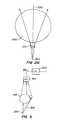
- FIG. 1shows a diagram of the optical microsphere
- FIG. 2Ashows optical ray tracing of dual microspheres
- FIG. 2Bshows the microspheres arranged in an enhanced signal mode
- FIGS. 2C and 2Dshows schematic views illustrating the magnitude of the signal received based upon orientation of the microspheres of FIGS. 2A and 2B , respectively.
- FIG. 3shows a block diagram of the electronics used in the rotation detector
- FIG. 4shows an optical microscope formed with a microsphere lens
- FIG. 5shows a laser with a microsphere lens
- FIG. 6shows a fiber with a microsphere lens.
- FIG. 1shows the use of a miniature optical element, e.g., a spheroid element, e.g. a microsphere, to change the characteristics of incoming light.
- the optical microsphere 100is a latex sphere or spheroid body, which has at least one round cross section, and in which the diameter D of the round cross section is between 0.8 and 2 um. More generally, the Latex particles of this type are commercially available from Bangs, or Interfacial Dynamics Corporation, or other companies.
- Incoming light 110is collimated by the sphere into collimated light 120 .
- the collimated lightcan be used for various purposes described herein.
- a first embodimentis used to sense high frequency rotational motion.
- An asymmetric fluorescent probeis formed of a microsphere pair 199 as shown in FIG. 2 A.
- the probeincludes a first latex microsphere 200 in optical and physical contact with a second latex microsphere 210 .
- the first microsphere 200is approximately 1.1 ⁇ m in diameter and forms a lensing portion.
- the smaller microsphere 210which can be between 0.5 um and 1 um, is fluorescently-labeled.
- the larger microsphere 200acts as a lens that enhances the collection efficiency of the optical system.
- FIG. 2Ashows optical ray tracing of the two microspheres.
- the rayoriginally starts at an angle ⁇ relative to the vertical 220 .
- the lensing microsphere 200After passing through the lensing microsphere 200 , the ray continues at an angle ⁇ ′ ⁇ ′′. If the lens is in water, the index of refraction of the water, n 1 , is 1.3.
- a photodetector 225monitors for the proper fluorescence from the marked sphere 210 .
- FIG. 2Bshows the microsphere pair oriented in alignment with the optical collection axis 220 .
- the fluorescence from the marked microsphere, or objective 210is enhanced by the lensing action of the lens 200 .
- the amount of collected light indicative of the marked lensis enhanced. This can be seen according to a geometric optics argument, as indicated in FIGS. 2C and 2D , which show schematic views comparing the magnitude of the signal received based upon orientation of the microspheres of FIGS. 2A and 2B , respectively.
- the angles of ray tracingare outlined in FIG. 2 A.
- the exit angle ⁇ ′ ⁇ ′′can be calculated as a function of the incident angle ⁇ .
- ⁇ ′′sin - 1 ⁇ ( n 2 n 1 ⁇ sin ⁇ ⁇ ⁇ ′ )
- the exit angle ⁇ ′ ⁇ ′′can be written in terms of the original angle ⁇ , the radii of the two spheres, r, ⁇ , and the indices of refraction, n 1 and n 2 .
- ⁇ ′ - ⁇ ′′′2 ⁇ sin - 1 ⁇ ( n 1 n 2 ⁇ sin ⁇ ( ⁇ + ⁇ ⁇ ( r , ⁇ , ⁇ ) ) ) - ⁇ - 2 ⁇ ⁇ ⁇ ( r , ⁇ , ⁇ ) .
- the equation abovereduces to ( 2 ⁇ n 1 n 2 - 1 ) ⁇ ⁇ .
- NAnumerical aperture
- FIG. 3shows a block diagram of the electronics of the system.
- a light source 300shines light along an optical axis 305 .
- the microsphere pair 199is located along this optical axis 305 .
- Light which shines through the microsphere pairimpinges on a photodetector 310 which produces a signal 315 indicative of the amount of incoming light.
- This signal 315is coupled to a controller element 320 such as a processor.
- the processormeasures the signal amplitude of the flourescently-marked portion of the light. From this amplitude, the processor calculates either an orientation angle of the pair 199 , or more simply a signal indicative of the rate of change of that orientation angle.
- the rate of changeindicates the rate of rotation of the pair 199 .
- FIG. 4shows the microlensing particle used in an optical scanning microscope.
- the microsphere lens 100is held within optical tweezers over a surface 415 to be scanned.
- the lensis indexed by an indexer 410 to scan the device across the surface 415 .
- the surfacecan be illuminated by a lamp 420 , causing light to reflect off the surface. Alternatively, the light from lamp 420 can cause fluorescence of the materials on the surface 415 .
- the light reflected from the surfaceshown as 425 , produces an output 430 which is collimated when the microsphere is directly above the surface area being imaged.
- the microlensenhances the numerical aperture of the objective 440 of the microscope 438 . This enables the microscope to have a high numerical aperture combined with a long working distance. Such a microscope avoids the usual trade off between light collecting capability (numerical aperture) and working distance.
- the microlens 100can actually be smaller than the wavelength of light that is used. This allows the microscope to resolve at a resolution that is higher than the diffraction limit of the radiation.
- Diode lasersare often small devices which produce a laser output over a very small scale.
- the laser outputis often Gaussian.
- a diode laserrelies on two mirrors shown as 500 and 502 to form a lasing cavity 504 .
- the present embodimentattaches microlens 506 directly on the output mirror 500 . This helps collimate the laser beam 510 .
- a microscopic lenscan help collimate almost all of the output light from the laser while minimally adding to the size of the laser.
- FIG. 6shows an optical fiber 600 using light collimated by a lens, to converge on the fiber end 605 .
- microsphere lens 100is coupled directly onto the end of the fiber, and centered on the end of the fiber. The microsphere increases the effective numerical aperture and hence improves the coupling efficiency of the light.
- the lenscan be attached to the desired surface, using a biochemical glue such as avidin or biotin, to hold the lens in place.
- a biochemical gluesuch as avidin or biotin
- the lenscould be properly positioned with optical tweezers, and melted or welded into place.
Landscapes
- Physics & Mathematics (AREA)
- General Physics & Mathematics (AREA)
- Optics & Photonics (AREA)
- Chemical & Material Sciences (AREA)
- Analytical Chemistry (AREA)
- Investigating, Analyzing Materials By Fluorescence Or Luminescence (AREA)
- Microscoopes, Condenser (AREA)
Abstract
Description
This application is a Division of 09/441,152 Nov. 12, 1999 now U.S. Pat. No. 6,614,598 which claims the benefit of the U.S. Provisional Application No. 60/108,385, filed on Nov. 12, 1998.
The work described in this application was supported by Grant No. PHY97-22417 awarded by the National Science Foundation.
Spherical polymer microspheres can be mass produced with extraordinary precision and low cost. Many uses for these microspheres have been developed that rely on the specific binding of a microsphere to a target, and the labelling of the polymer microsphere with various dyes or magnetic material.
Spherical glass lenses greater than 1 mm in diameter are used for coupling light into or out of fibers as well as for relaying images across a short distance.
The present application describes new optical applications of spherical polymer microspheres less than 10 microns in diameter.
The present application teaches a special microlensing particle and applications of the particle. According to the present invention, a latex microsphere of diameter 0.3 μm-4 μm is obtained. Latex microspheres of this type are commercially available and have been used in pregnancy tests and other applications that do not exploit their optical properties.
According to the present system, the latex microsphere is preferably less than 10 μm in diameter, more preferably 1 to 2 μm in diameter. The latex microsphere is used in combination with an optical imaging element.
Applications of the latex microsphere include a micro lensing rotational probe for use in detecting high frequency rotational motion, a scanning microscope, and a diode laser collimator device.
These and other aspects will now be described in detail with respect to the accompanying drawings, wherein:
It was found by the present inventors that the latex sphere has a collimating effect on incoming light. Incominglight 110 is collimated by the sphere into collimatedlight 120. The collimated light can be used for various purposes described herein.
A first embodiment is used to sense high frequency rotational motion. An asymmetric fluorescent probe is formed of amicrosphere pair 199 as shown in FIG.2A. The probe includes afirst latex microsphere 200 in optical and physical contact with asecond latex microsphere 210. Thefirst microsphere 200 is approximately 1.1 μm in diameter and forms a lensing portion. Thesmaller microsphere 210, which can be between 0.5 um and 1 um, is fluorescently-labeled. Thelarger microsphere 200 acts as a lens that enhances the collection efficiency of the optical system.
The two microspheres are connected together. Light is passed by the optical combination of the two spheres.FIG. 2A shows optical ray tracing of the two microspheres. The ray originally starts at an angle θ relative to the vertical220. After passing through thelensing microsphere 200, the ray continues at an angle φ′−θ″. If the lens is in water, the index of refraction of the water, n1, is 1.3. Themicrosphere 200 has an index of refraction, n2, =1.59 (for polystyrene). Aphotodetector 225 monitors for the proper fluorescence from themarked sphere 210.
When themicrosphere pair 199 is oriented relative to thephotodetector 225 as shown inFIG. 2A , light passes through the flourescently-markedmicrosphere 210 directly to thephotodetector 225, and a relatively dim signal of themarked sphere 210 is obtained.
The angles of ray tracing are outlined in FIG.2A. The exit angle φ′−θ″ can be calculated as a function of the incident angle θ. Thefluorescent microsphere 210 is approximated as a point particle located a distance δ from the lensing microsphere. Using geometry, it can be seen that
φ′=π−(π2θ′+φ)=2θ′−φ
φ′=π−(π2θ′+φ)=2θ′−φ
Applying Snell's law at the top interface of the lensing microsphere:
- where n2is the index of refraction of the lensing microsphere and n1is the index of refraction of the surrounding medium (typically water). Applying Snell's law at the bottom interface gives
- where n2is the index of refraction of the lensing microsphere and n1is the index of refraction of the surrounding medium (typically water). Applying Snell's law at the bottom interface gives
Then, direct substitution of equation (3) into equation (2), shows that
θ″=φ+θ
θ″=φ+θ
Using the law of sines, this can be rewritten as
- and then explicitly find the angle φ as a function of r, θ, and δ:
- and then explicitly find the angle φ as a function of r, θ, and δ:
Finally, the exit angle φ′−θ″ can be written in terms of the original angle θ, the radii of the two spheres, r, δ, and the indices of refraction, n1and n2.
For δ<<t, φ<<θ. The exit angle is then given by
Typical realizable values of n1and n2are for water, n1=1.3 and polystyrene, n2=1.59. For small θ, the equation above reduces to
This gives an exit angle of 0.64·θ for a ray entering at an angle θ. Since the exit angle is always less than the original angle, the lensing microsphere focuses rays from the fluorescent microspheres and enhances the optical signal.
This gives an exit angle of 0.64·θ for a ray entering at an angle θ. Since the exit angle is always less than the original angle, the lensing microsphere focuses rays from the fluorescent microspheres and enhances the optical signal.
The enhancement in the observed optical signal also depends on the numerical aperture of the objective. The numerical aperture (NA) is defined as NA=n sin θ0, where θ0is the collection angle. For the present objective (20x, 0.4 NA) in air θ0=23.60. The equation shows that the focusing microsphere increases the angle of collection to 43.5°. This corresponds to an effective NA of 0.69. The epi-fluorescent intensity in proportional to NA4, so the intensity enhancement should relate (0.69/0.4)4≈9 times.
The rate of change indicates the rate of rotation of thepair 199.
The above has described one embodiment of these miniature lenses, but other applications are also possible.FIG. 4 shows the microlensing particle used in an optical scanning microscope. Themicrosphere lens 100 is held within optical tweezers over asurface 415 to be scanned. The lens is indexed by anindexer 410 to scan the device across thesurface 415. The surface can be illuminated by alamp 420, causing light to reflect off the surface. Alternatively, the light fromlamp 420 can cause fluorescence of the materials on thesurface 415.
The light reflected from the surface, shown as425, produces anoutput 430 which is collimated when the microsphere is directly above the surface area being imaged.
The microlens enhances the numerical aperture of theobjective 440 of themicroscope 438. This enables the microscope to have a high numerical aperture combined with a long working distance. Such a microscope avoids the usual trade off between light collecting capability (numerical aperture) and working distance.
In one mode, themicrolens 100 can actually be smaller than the wavelength of light that is used. This allows the microscope to resolve at a resolution that is higher than the diffraction limit of the radiation.
Another application of the microlens is shown in FIG.5. Diode lasers are often small devices which produce a laser output over a very small scale. The laser output is often Gaussian.
A diode laser relies on two mirrors shown as500 and502 to form alasing cavity 504. The present embodiment attaches microlens506 directly on theoutput mirror 500. This helps collimate thelaser beam 510. Moreover, since the laser itself is often on the order of size of 10 μm. a microscopic lens can help collimate almost all of the output light from the laser while minimally adding to the size of the laser.
In the embodiments ofFIGS. 5 and 6 , the lens can be attached to the desired surface, using a biochemical glue such as avidin or biotin, to hold the lens in place. Alternatively, the lens could be properly positioned with optical tweezers, and melted or welded into place.
Other modifications are contemplated.
Claims (12)
1. An optical device comprising:
a spherical lensing element having a diameter of 10 μm or less, the spherical lensing element configured to collimate incident light to generate a collimated light beam; and an optical imaging element receiving the collimated light beam,
wherein the incident light is generated by a source element having a diameter of 10 μm or less that is in physical contact with the spherical lensing element, the diameter of the source element is smaller than the diameter of the of the lensing element.
2. The optical device ofclaim 1 wherein the incident light is generated by fluorescence of the source element.
3. The optical device ofclaim 1 wherein the optical imaging element is configured to detect an amplitude of the collimated light beam.
4. The optical device ofclaim 3 wherein the optical imaging element is configured to detect an angle of orientation of the linked source and lensing elements relative to the optical imaging element.
5. The optical device ofclaim 3 wherein the optical imaging element is configured to detect a rate of change of an angle of orientation of the joined source and lensing elements relative to the optical imaging element.
6. The optical device ofclaim 3 wherein the optical imaging element comprises a photodetector.
7. The optical device ofclaim 6 wherein the lensing element is configured to receive the incident light reflected from the surface.
8. A method of focusing light comprising:
collimating incident light with a spherical lensing element having a diameter of 10 μm or less, and
generating the incident light from a source element having a diameter of 10 μm or less in physical contact with the spherical lensing element, the diameter of the source element is smaller than the diameter of the lensing element.
9. The method ofclaim 8 wherein the incident light is generated by fluorescence of the source element.
10. A method of focusing light comprising collimating incident light with a spherical lensing element having a diameter of 10 μm or less, and
detecting an amplitude of the collimated light.
11. The method ofclaim 10 further comprising correlating the amplitude of the collimated light with an angle of orientation of the linked source and lensing elements relative to an optical imaging element.
12. The method ofclaim 11 wherein the correlation comprises determining a rate of change of an angle of orientation of joined source and lensing elements relative to the optical imaging element.
Priority Applications (2)
| Application Number | Priority Date | Filing Date | Title |
|---|---|---|---|
| US10/603,502US6958865B1 (en) | 1998-11-12 | 2003-06-24 | Microlicensing particles and applications |
| US11/095,332US7248413B2 (en) | 1998-11-12 | 2005-03-30 | Microlensing particles and applications |
Applications Claiming Priority (3)
| Application Number | Priority Date | Filing Date | Title |
|---|---|---|---|
| US10838598P | 1998-11-12 | 1998-11-12 | |
| US09/441,152US6614598B1 (en) | 1998-11-12 | 1999-11-12 | Microlensing particles and applications |
| US10/603,502US6958865B1 (en) | 1998-11-12 | 2003-06-24 | Microlicensing particles and applications |
Related Parent Applications (1)
| Application Number | Title | Priority Date | Filing Date |
|---|---|---|---|
| US09/441,152DivisionUS6614598B1 (en) | 1998-11-12 | 1999-11-12 | Microlensing particles and applications |
Related Child Applications (1)
| Application Number | Title | Priority Date | Filing Date |
|---|---|---|---|
| US11/095,332DivisionUS7248413B2 (en) | 1998-11-12 | 2005-03-30 | Microlensing particles and applications |
Publications (1)
| Publication Number | Publication Date |
|---|---|
| US6958865B1true US6958865B1 (en) | 2005-10-25 |
Family
ID=34811954
Family Applications (2)
| Application Number | Title | Priority Date | Filing Date |
|---|---|---|---|
| US10/603,502Expired - Fee RelatedUS6958865B1 (en) | 1998-11-12 | 2003-06-24 | Microlicensing particles and applications |
| US11/095,332Expired - Fee RelatedUS7248413B2 (en) | 1998-11-12 | 2005-03-30 | Microlensing particles and applications |
Family Applications After (1)
| Application Number | Title | Priority Date | Filing Date |
|---|---|---|---|
| US11/095,332Expired - Fee RelatedUS7248413B2 (en) | 1998-11-12 | 2005-03-30 | Microlensing particles and applications |
Country Status (1)
| Country | Link |
|---|---|
| US (2) | US6958865B1 (en) |
Cited By (3)
| Publication number | Priority date | Publication date | Assignee | Title |
|---|---|---|---|---|
| US8697435B2 (en) | 2009-08-31 | 2014-04-15 | Mbio Diagnostics, Inc. | Integrated sample preparation and analyte detection |
| WO2013052840A3 (en)* | 2011-10-07 | 2014-05-22 | Biolase, Inc. | Light diluting toothbrush bristles |
| US9205468B2 (en) | 2009-11-30 | 2015-12-08 | Fluidigm Corporation | Microfluidic device regeneration |
Families Citing this family (48)
| Publication number | Priority date | Publication date | Assignee | Title |
|---|---|---|---|---|
| US6221654B1 (en) | 1996-09-25 | 2001-04-24 | California Institute Of Technology | Method and apparatus for analysis and sorting of polynucleotides based on size |
| US7214298B2 (en)* | 1997-09-23 | 2007-05-08 | California Institute Of Technology | Microfabricated cell sorter |
| US8709153B2 (en) | 1999-06-28 | 2014-04-29 | California Institute Of Technology | Microfludic protein crystallography techniques |
| US7459022B2 (en) | 2001-04-06 | 2008-12-02 | California Institute Of Technology | Microfluidic protein crystallography |
| US7144616B1 (en) | 1999-06-28 | 2006-12-05 | California Institute Of Technology | Microfabricated elastomeric valve and pump systems |
| US7306672B2 (en) | 2001-04-06 | 2007-12-11 | California Institute Of Technology | Microfluidic free interface diffusion techniques |
| DK1065378T3 (en) | 1999-06-28 | 2002-07-29 | California Inst Of Techn | Elastomeric micropump and micro valve systems |
| US8052792B2 (en)* | 2001-04-06 | 2011-11-08 | California Institute Of Technology | Microfluidic protein crystallography techniques |
| US20050118073A1 (en)* | 2003-11-26 | 2005-06-02 | Fluidigm Corporation | Devices and methods for holding microfluidic devices |
| US7867763B2 (en) | 2004-01-25 | 2011-01-11 | Fluidigm Corporation | Integrated chip carriers with thermocycler interfaces and methods of using the same |
| US7351376B1 (en) | 2000-06-05 | 2008-04-01 | California Institute Of Technology | Integrated active flux microfluidic devices and methods |
| WO2002023163A1 (en) | 2000-09-15 | 2002-03-21 | California Institute Of Technology | Microfabricated crossflow devices and methods |
| AU2002230524A1 (en) | 2000-11-16 | 2002-05-27 | California Institute Of Technology | Apparatus and methods for conducting assays and high throughput screening |
| US7691333B2 (en) | 2001-11-30 | 2010-04-06 | Fluidigm Corporation | Microfluidic device and methods of using same |
| JP4355210B2 (en) | 2001-11-30 | 2009-10-28 | フルイディグム コーポレイション | Microfluidic device and method of using microfluidic device |
| WO2003085379A2 (en) | 2002-04-01 | 2003-10-16 | Fluidigm Corporation | Microfluidic particle-analysis systems |
| US8220494B2 (en)* | 2002-09-25 | 2012-07-17 | California Institute Of Technology | Microfluidic large scale integration |
| JP2006501056A (en) | 2002-09-25 | 2006-01-12 | カリフォルニア インスティテュート オブ テクノロジー | Micro fluid large scale integration |
| EP1546412B1 (en)* | 2002-10-02 | 2014-05-21 | California Institute Of Technology | Microfluidic nucleic acid analysis |
| US7604965B2 (en) | 2003-04-03 | 2009-10-20 | Fluidigm Corporation | Thermal reaction device and method for using the same |
| US8828663B2 (en) | 2005-03-18 | 2014-09-09 | Fluidigm Corporation | Thermal reaction device and method for using the same |
| CA2526368A1 (en) | 2003-05-20 | 2004-12-02 | Fluidigm Corporation | Method and system for microfluidic device and imaging thereof |
| US7042649B2 (en)* | 2003-08-11 | 2006-05-09 | California Institute Of Technology | Microfabricated rubber microscope using soft solid immersion lenses |
| US7407799B2 (en) | 2004-01-16 | 2008-08-05 | California Institute Of Technology | Microfluidic chemostat |
| CN103884698B (en) | 2004-06-07 | 2017-04-12 | 先锋生物科技股份有限公司 | Optical lens system and method for microfluidic devices |
| WO2006060748A2 (en) | 2004-12-03 | 2006-06-08 | California Institute Of Technology | Microfluidic sieve valves |
| US8206593B2 (en) | 2004-12-03 | 2012-06-26 | Fluidigm Corporation | Microfluidic chemical reaction circuits |
| EP1882189A2 (en) | 2005-04-20 | 2008-01-30 | Fluidigm Corporation | Analysis engine and database for manipulating parameters for fluidic systems on a chip |
| US20070054293A1 (en)* | 2005-08-30 | 2007-03-08 | California Institute Of Technology | Microfluidic chaotic mixing systems and methods |
| WO2007033385A2 (en)* | 2005-09-13 | 2007-03-22 | Fluidigm Corporation | Microfluidic assay devices and methods |
| US7815868B1 (en) | 2006-02-28 | 2010-10-19 | Fluidigm Corporation | Microfluidic reaction apparatus for high throughput screening |
| US8828661B2 (en) | 2006-04-24 | 2014-09-09 | Fluidigm Corporation | Methods for detection and quantification of nucleic acid or protein targets in a sample |
| US8055034B2 (en) | 2006-09-13 | 2011-11-08 | Fluidigm Corporation | Methods and systems for image processing of microfluidic devices |
| WO2008067552A2 (en)* | 2006-11-30 | 2008-06-05 | Fluidigm Corporation | Method and apparatus for biological sample analysis |
| EP2125219B1 (en) | 2007-01-19 | 2016-08-10 | Fluidigm Corporation | High precision microfluidic devices and methods |
| MX2010002556A (en)* | 2007-09-07 | 2010-08-02 | Fluidigm Corp | Copy number variation determination, methods and systems. |
| US9157116B2 (en) | 2008-02-08 | 2015-10-13 | Fluidigm Corporation | Combinatorial amplification and detection of nucleic acids |
| CN102056838B (en) | 2008-04-11 | 2013-07-03 | 弗卢丁公司 | Microfluidic devices and methods |
| CN102165076B (en) | 2008-07-25 | 2014-07-09 | 弗卢丁公司 | Method and system for manufacturing integrated fluidic chips |
| US8617488B2 (en) | 2008-08-07 | 2013-12-31 | Fluidigm Corporation | Microfluidic mixing and reaction systems for high efficiency screening |
| US8058630B2 (en)* | 2009-01-16 | 2011-11-15 | Fluidigm Corporation | Microfluidic devices and methods |
| US8551787B2 (en)* | 2009-07-23 | 2013-10-08 | Fluidigm Corporation | Microfluidic devices and methods for binary mixing |
| SG169918A1 (en) | 2009-10-02 | 2011-04-29 | Fluidigm Corp | Microfluidic devices with removable cover and methods of fabrication and application |
| US9353406B2 (en) | 2010-10-22 | 2016-05-31 | Fluidigm Corporation | Universal probe assay methods |
| US9168531B2 (en) | 2011-03-24 | 2015-10-27 | Fluidigm Corporation | Method for thermal cycling of microfluidic samples |
| EP2707507B1 (en) | 2011-05-09 | 2017-11-01 | Fluidigm Corporation | Probe based nucleic acid detection |
| US9644231B2 (en) | 2011-05-09 | 2017-05-09 | Fluidigm Corporation | Nucleic acid detection using probes |
| US11408584B1 (en) | 2021-06-29 | 2022-08-09 | AlPhotonics Limited | Illuminating device with spherical modulator |
Citations (30)
| Publication number | Priority date | Publication date | Assignee | Title |
|---|---|---|---|---|
| US4155962A (en) | 1977-05-25 | 1979-05-22 | Neefe Optical Laboratory, Inc. | Method of removing molded lenses from the mold |
| US4540534A (en) | 1983-10-11 | 1985-09-10 | American Optical Corporation | Apparatus and method for injection molding lenses |
| US4798428A (en) | 1986-10-14 | 1989-01-17 | Ncr Corporation | Fiber optic coupling system |
| EP0362993A2 (en) | 1988-10-05 | 1990-04-11 | Hewlett-Packard Company | Nonimaging light source |
| US5121256A (en) | 1991-03-14 | 1992-06-09 | The Board Of Trustees Of The Leland Stanford Junior University | Lithography system employing a solid immersion lens |
| US5171995A (en) | 1990-09-28 | 1992-12-15 | Bruker Analytische Mebtechnik Gmbh | Sample holder for optical spectrometer and method for taking a spectrum |
| US5317452A (en) | 1992-11-17 | 1994-05-31 | Harvard University | Aligning and attaching a lens to a source of emitted light using light pressure force |
| JPH081810A (en)* | 1994-06-20 | 1996-01-09 | Koichi Ishida | Microlens formed by isotropic etching |
| US5583351A (en)* | 1993-04-22 | 1996-12-10 | Sharp Kabushiki Kaisha | Color display/detector |
| US5729393A (en) | 1996-04-03 | 1998-03-17 | Digital Papyrus Corporation | Optical flying head with solid immersion lens having raised central surface facing medium |
| WO1998019654A1 (en) | 1996-11-04 | 1998-05-14 | The Procter & Gamble Company | Hair mousse composition comprising silicone emulsion |
| US5764613A (en) | 1995-05-18 | 1998-06-09 | Sony Corporation | optical pickup apparatus |
| US5776191A (en) | 1982-02-05 | 1998-07-07 | Staar Surgical Company | Fixation system for intraocular lens structures |
| US5815306A (en) | 1996-12-24 | 1998-09-29 | Xerox Corporation | "Eggcrate" substrate for a twisting ball display |
| JPH11197587A (en) | 1998-01-19 | 1999-07-27 | Ishikawajima Harima Heavy Ind Co Ltd | Wing parts masking device |
| US5939709A (en) | 1997-06-19 | 1999-08-17 | Ghislain; Lucien P. | Scanning probe optical microscope using a solid immersion lens |
| JP2000089004A (en) | 1998-09-16 | 2000-03-31 | Minolta Co Ltd | Solid immersion lens and manufacture thereof |
| US6181478B1 (en) | 1999-07-16 | 2001-01-30 | Michael Mandella | Ellipsoidal solid immersion lens |
| US6200737B1 (en)* | 1995-08-24 | 2001-03-13 | Trustees Of Tufts College | Photodeposition method for fabricating a three-dimensional, patterned polymer microstructure |
| US6236513B1 (en) | 1999-06-30 | 2001-05-22 | Quantum Corporation | Integrated objective/solid immersion lens for near field recording |
| US6270696B1 (en) | 1996-06-03 | 2001-08-07 | Terastor Corporation | Method of fabricating and integrating an optical assembly into a flying head |
| US6277545B1 (en) | 1998-01-14 | 2001-08-21 | Pioneer Electronic Corporation | Method of manufacturing optical disc master plate |
| US6298026B1 (en) | 1998-09-24 | 2001-10-02 | Sanyo Electric Co., Ltd. | Magneto-optical head apparatus using evanescent light |
| US6301055B1 (en) | 2000-08-16 | 2001-10-09 | California Institute Of Technology | Solid immersion lens structures and methods for producing solid immersion lens structures |
| US6307689B1 (en) | 1998-10-21 | 2001-10-23 | Sony Corporation | Optical head and drive device for optical recording medium |
| US6503831B2 (en)* | 1997-10-14 | 2003-01-07 | Patterning Technologies Limited | Method of forming an electronic device |
| US20030032204A1 (en)* | 2001-07-19 | 2003-02-13 | Walt David R. | Optical array device and methods of use thereof for screening, analysis and manipulation of particles |
| US6548171B1 (en)* | 1998-11-10 | 2003-04-15 | Emilio Barbera-Guillem | Fluorescent nanocrystal-embedded microspheres for fluorescence analyses |
| US6614598B1 (en) | 1998-11-12 | 2003-09-02 | Institute Of Technology, California | Microlensing particles and applications |
| US6781690B2 (en)* | 1999-05-17 | 2004-08-24 | New Mexico State University Technology Transfer Corporation | Sensors employing nanoparticles and microcavities |
Family Cites Families (4)
| Publication number | Priority date | Publication date | Assignee | Title |
|---|---|---|---|---|
| JP3506817B2 (en)* | 1995-07-26 | 2004-03-15 | クラリアント インターナショナル リミテッド | Radiation sensitive composition |
| US6296026B1 (en)* | 1997-06-26 | 2001-10-02 | Advanced Technology Materials, Inc. | Chemical delivery system having purge system utilizing multiple purge techniques |
| JP2001023106A (en)* | 1999-07-06 | 2001-01-26 | Fujitsu Ltd | Magnetic disk drive |
| US7042649B2 (en) | 2003-08-11 | 2006-05-09 | California Institute Of Technology | Microfabricated rubber microscope using soft solid immersion lenses |
- 2003
- 2003-06-24USUS10/603,502patent/US6958865B1/ennot_activeExpired - Fee Related
- 2005
- 2005-03-30USUS11/095,332patent/US7248413B2/ennot_activeExpired - Fee Related
Patent Citations (34)
| Publication number | Priority date | Publication date | Assignee | Title |
|---|---|---|---|---|
| US4155962A (en) | 1977-05-25 | 1979-05-22 | Neefe Optical Laboratory, Inc. | Method of removing molded lenses from the mold |
| US5776191A (en) | 1982-02-05 | 1998-07-07 | Staar Surgical Company | Fixation system for intraocular lens structures |
| US4540534A (en) | 1983-10-11 | 1985-09-10 | American Optical Corporation | Apparatus and method for injection molding lenses |
| US4798428A (en) | 1986-10-14 | 1989-01-17 | Ncr Corporation | Fiber optic coupling system |
| EP0362993A2 (en) | 1988-10-05 | 1990-04-11 | Hewlett-Packard Company | Nonimaging light source |
| US5171995A (en) | 1990-09-28 | 1992-12-15 | Bruker Analytische Mebtechnik Gmbh | Sample holder for optical spectrometer and method for taking a spectrum |
| US5121256A (en) | 1991-03-14 | 1992-06-09 | The Board Of Trustees Of The Leland Stanford Junior University | Lithography system employing a solid immersion lens |
| US5317452A (en) | 1992-11-17 | 1994-05-31 | Harvard University | Aligning and attaching a lens to a source of emitted light using light pressure force |
| US5583351A (en)* | 1993-04-22 | 1996-12-10 | Sharp Kabushiki Kaisha | Color display/detector |
| JPH081810A (en)* | 1994-06-20 | 1996-01-09 | Koichi Ishida | Microlens formed by isotropic etching |
| US5764613A (en) | 1995-05-18 | 1998-06-09 | Sony Corporation | optical pickup apparatus |
| US6200737B1 (en)* | 1995-08-24 | 2001-03-13 | Trustees Of Tufts College | Photodeposition method for fabricating a three-dimensional, patterned polymer microstructure |
| US5729393A (en) | 1996-04-03 | 1998-03-17 | Digital Papyrus Corporation | Optical flying head with solid immersion lens having raised central surface facing medium |
| US6270696B1 (en) | 1996-06-03 | 2001-08-07 | Terastor Corporation | Method of fabricating and integrating an optical assembly into a flying head |
| WO1998019654A1 (en) | 1996-11-04 | 1998-05-14 | The Procter & Gamble Company | Hair mousse composition comprising silicone emulsion |
| US5815306A (en) | 1996-12-24 | 1998-09-29 | Xerox Corporation | "Eggcrate" substrate for a twisting ball display |
| US5939709A (en) | 1997-06-19 | 1999-08-17 | Ghislain; Lucien P. | Scanning probe optical microscope using a solid immersion lens |
| US20030076649A1 (en)* | 1997-10-14 | 2003-04-24 | Stuart Speakman | Method of forming an electronic device |
| US6503831B2 (en)* | 1997-10-14 | 2003-01-07 | Patterning Technologies Limited | Method of forming an electronic device |
| US6277545B1 (en) | 1998-01-14 | 2001-08-21 | Pioneer Electronic Corporation | Method of manufacturing optical disc master plate |
| JPH11197587A (en) | 1998-01-19 | 1999-07-27 | Ishikawajima Harima Heavy Ind Co Ltd | Wing parts masking device |
| JP2000089004A (en) | 1998-09-16 | 2000-03-31 | Minolta Co Ltd | Solid immersion lens and manufacture thereof |
| US6369957B1 (en) | 1998-09-16 | 2002-04-09 | Minolta Co., Ltd. | Solid immersion lens and production method thereof |
| US6298026B1 (en) | 1998-09-24 | 2001-10-02 | Sanyo Electric Co., Ltd. | Magneto-optical head apparatus using evanescent light |
| US6307689B1 (en) | 1998-10-21 | 2001-10-23 | Sony Corporation | Optical head and drive device for optical recording medium |
| US6548171B1 (en)* | 1998-11-10 | 2003-04-15 | Emilio Barbera-Guillem | Fluorescent nanocrystal-embedded microspheres for fluorescence analyses |
| US6614598B1 (en) | 1998-11-12 | 2003-09-02 | Institute Of Technology, California | Microlensing particles and applications |
| US6781690B2 (en)* | 1999-05-17 | 2004-08-24 | New Mexico State University Technology Transfer Corporation | Sensors employing nanoparticles and microcavities |
| US6236513B1 (en) | 1999-06-30 | 2001-05-22 | Quantum Corporation | Integrated objective/solid immersion lens for near field recording |
| US6181478B1 (en) | 1999-07-16 | 2001-01-30 | Michael Mandella | Ellipsoidal solid immersion lens |
| US6301055B1 (en) | 2000-08-16 | 2001-10-09 | California Institute Of Technology | Solid immersion lens structures and methods for producing solid immersion lens structures |
| US6560030B2 (en) | 2000-08-16 | 2003-05-06 | California Institute Of Technology | Solid immersion lens structures and methods for producing solid immersion lens structures |
| US6608726B2 (en) | 2000-08-16 | 2003-08-19 | California Institute Of Technology | Solid immersion lens structures and methods for producing solid immersion lens structures |
| US20030032204A1 (en)* | 2001-07-19 | 2003-02-13 | Walt David R. | Optical array device and methods of use thereof for screening, analysis and manipulation of particles |
Non-Patent Citations (15)
| Title |
|---|
| Berg, Howard C. "Dynamic properties of bacterial Flagellar motors", Nature, vol. 248, May 3, 1974. |
| Berry, Richard M. et al. "Absence of a barrier to backwards rotation of the bacterial flagellar motor demonstrated with optical tweezers", Natl. Acad. Sci, USA. vol. 94, pp. 14433-14437, (Dec. 1997). |
| Brody et al., "A Self-Assembled Microlensing Rotational Probe," Applied Physics Letters, 74(1):144-146 (1999). |
| Elson, Elliot L. "Fluorscence Correlation Spectroscopy and Photobleching Recovery", Ann. Rev. Phys. Chem. (1985):36:379-406. |
| Finer, Jeffrey T. et al. "Single myosin molecule mechanics: piconewton forces and nanometre steps," Nature, vol. 368, Mar. 10, 1994, pp. 113-119. |
| Jameson et al., "Time-Resolved Fluorescence in Biology and Biochemistry," chapter 4, pp. 105-133 from Biophysical and Biochemical Aspects Of Fluorescence Spectroscopy, eds. Dewey, Plenum Press (no date available). |
| Kinosita, Kazuhiko Jr. et al. "F.sub.1 -ATPase: A rotary motor made of a single molecule", Cell, vol. 93, pp. 21-24, Apr. 3, 1998. |
| Mervis, J. et al. "Aligning and attaching a lens to an optical fiber using light pressure force", Optics Letters, vol. 18, No. 5, Mar. 1, 1993, p. 325. |
| Miguez, H. et al. "Photonic crystal properties of packed submicrometric SIO.sub.2 spheres", American Institute of Physics (1997), 3 pages. |
| Patent Abstracts of Japan, publication No.: 08-001810, publication date: Jan. 9, 1996, abstract only. |
| Perkins, Thomas T. "Relaxation of a single DNA molecule observed by optical microscopy" Science, vol. 264, May 6, 1994. |
| Shingyoji, Chikako et al. "Dynein arms are oscillating force generators", Nature, vol. 393, Jun. 18, 1998. |
| Silverman, Michal et al. "Flagellar rotation and the mechanism of bacterial motility", Nature vol. 249, May 3, (1974). |
| Smith, Stephen P. et al. "Inexpensive optical tweezers for undergraduate laboratories", Am. J. Phys. 67 (1), Jan. 1999, pp. 26-35. |
| Svoboda, Karel et al. "Direct observation of kinesin stepping by optical trapping interferometry", Nature, vol. 365, Oct. 21, 1993. |
Cited By (3)
| Publication number | Priority date | Publication date | Assignee | Title |
|---|---|---|---|---|
| US8697435B2 (en) | 2009-08-31 | 2014-04-15 | Mbio Diagnostics, Inc. | Integrated sample preparation and analyte detection |
| US9205468B2 (en) | 2009-11-30 | 2015-12-08 | Fluidigm Corporation | Microfluidic device regeneration |
| WO2013052840A3 (en)* | 2011-10-07 | 2014-05-22 | Biolase, Inc. | Light diluting toothbrush bristles |
Also Published As
| Publication number | Publication date |
|---|---|
| US7248413B2 (en) | 2007-07-24 |
| US20050168828A1 (en) | 2005-08-04 |
Similar Documents
| Publication | Publication Date | Title |
|---|---|---|
| US6958865B1 (en) | Microlicensing particles and applications | |
| US6614598B1 (en) | Microlensing particles and applications | |
| US4604520A (en) | Optical near-field scanning microscope | |
| US7560270B2 (en) | Biochip cartridge and biochip reader | |
| US7787197B2 (en) | Beam-adjusting optics | |
| US6396580B1 (en) | Method and device for polychromatic fluorescence correlation spectroscopy | |
| CN113008768B (en) | Reflective fluorescence collection device for flow cytometry | |
| EP0433613A1 (en) | Microscopic spectrometer with Cassegrain objective | |
| CN202102170U (en) | System for realizing total internal reflection fluorescence microscopy by using concentric double conical surface mirror | |
| US6219476B1 (en) | Multiple light source unit and optical system using the same | |
| US8269157B2 (en) | Optical imaging system | |
| JPH08254650A (en) | Focus detection device | |
| JPH0519195A (en) | Optical device | |
| EP0703543A1 (en) | Wand scanning apparatus | |
| JPH0694613A (en) | Infrared microscopic measuring apparatus | |
| US6477298B1 (en) | Collection mode lens system | |
| Fletcher et al. | Refraction contrast imaging with a scanning microlens | |
| KR102634125B1 (en) | Photo-induced force microcscope having optics module causing total reflection | |
| RU2064670C1 (en) | Device for measuring intensity of dissipated light | |
| JPH08261734A (en) | Shape measuring device | |
| CN223051198U (en) | Focal plane detection device | |
| EP0490369B1 (en) | Wavelength converter | |
| JPH08271209A (en) | Optical waveguide displacement sensor and hemispherical lens used therefor | |
| JPH0540225A (en) | Scanning microscope | |
| TWI637162B (en) | Radial polarized light surface plasma excitation device |
Legal Events
| Date | Code | Title | Description |
|---|---|---|---|
| FPAY | Fee payment | Year of fee payment:4 | |
| FPAY | Fee payment | Year of fee payment:8 | |
| FEPP | Fee payment procedure | Free format text:PAT HOLDER NO LONGER CLAIMS SMALL ENTITY STATUS, ENTITY STATUS SET TO UNDISCOUNTED (ORIGINAL EVENT CODE: STOL); ENTITY STATUS OF PATENT OWNER: LARGE ENTITY | |
| REMI | Maintenance fee reminder mailed | ||
| LAPS | Lapse for failure to pay maintenance fees | Free format text:PATENT EXPIRED FOR FAILURE TO PAY MAINTENANCE FEES (ORIGINAL EVENT CODE: EXP.) | |
| STCH | Information on status: patent discontinuation | Free format text:PATENT EXPIRED DUE TO NONPAYMENT OF MAINTENANCE FEES UNDER 37 CFR 1.362 | |
| FP | Lapsed due to failure to pay maintenance fee | Effective date:20171025 |