US6957574B2 - Well integrity monitoring system - Google Patents
Well integrity monitoring systemDownload PDFInfo
- Publication number
- US6957574B2 US6957574B2US10/441,233US44123303AUS6957574B2US 6957574 B2US6957574 B2US 6957574B2US 44123303 AUS44123303 AUS 44123303AUS 6957574 B2US6957574 B2US 6957574B2
- Authority
- US
- United States
- Prior art keywords
- casing
- sensor
- fiber optic
- strain
- coils
- Prior art date
- Legal status (The legal status is an assumption and is not a legal conclusion. Google has not performed a legal analysis and makes no representation as to the accuracy of the status listed.)
- Expired - Lifetime, expires
Links
- 238000012544monitoring processMethods0.000titleabstractdescription23
- 238000000034methodMethods0.000claimsabstractdescription50
- 239000013307optical fiberSubstances0.000claimsabstractdescription17
- 238000004458analytical methodMethods0.000claimsabstractdescription8
- 239000000835fiberSubstances0.000claimsdescription54
- 230000003287optical effectEffects0.000claimsdescription8
- 230000037361pathwayEffects0.000claims2
- 230000008878couplingEffects0.000claims1
- 238000010168coupling processMethods0.000claims1
- 238000005859coupling reactionMethods0.000claims1
- 230000001131transforming effectEffects0.000claims1
- 208000013201Stress fractureDiseases0.000abstractdescription27
- 230000003068static effectEffects0.000abstractdescription5
- 238000001514detection methodMethods0.000description11
- 238000001228spectrumMethods0.000description7
- 230000015572biosynthetic processEffects0.000description6
- 238000004519manufacturing processMethods0.000description6
- 238000013459approachMethods0.000description5
- 239000004593EpoxySubstances0.000description4
- 238000011161developmentMethods0.000description4
- 238000013461designMethods0.000description3
- 239000002184metalSubstances0.000description3
- 238000012545processingMethods0.000description3
- 238000005070samplingMethods0.000description3
- IJGRMHOSHXDMSA-UHFFFAOYSA-NAtomic nitrogenChemical compoundN#NIJGRMHOSHXDMSA-UHFFFAOYSA-N0.000description2
- 229910000831SteelInorganic materials0.000description2
- 230000008901benefitEffects0.000description2
- 239000004568cementSubstances0.000description2
- 238000006243chemical reactionMethods0.000description2
- 230000006835compressionEffects0.000description2
- 238000007906compressionMethods0.000description2
- 239000012530fluidSubstances0.000description2
- 238000002955isolationMethods0.000description2
- 239000010959steelSubstances0.000description2
- UFHFLCQGNIYNRP-UHFFFAOYSA-NHydrogenChemical compound[H][H]UFHFLCQGNIYNRP-UHFFFAOYSA-N0.000description1
- 230000009471actionEffects0.000description1
- 239000002313adhesive filmSubstances0.000description1
- 230000004075alterationEffects0.000description1
- 238000010420art techniqueMethods0.000description1
- 230000002238attenuated effectEffects0.000description1
- 238000005452bendingMethods0.000description1
- 230000008859changeEffects0.000description1
- 238000005253claddingMethods0.000description1
- 238000004891communicationMethods0.000description1
- 238000012790confirmationMethods0.000description1
- 239000000470constituentSubstances0.000description1
- 238000010276constructionMethods0.000description1
- 238000007796conventional methodMethods0.000description1
- 238000007405data analysisMethods0.000description1
- 238000009826distributionMethods0.000description1
- 238000005553drillingMethods0.000description1
- 230000007613environmental effectEffects0.000description1
- 230000004927fusionEffects0.000description1
- 238000007526fusion splicingMethods0.000description1
- 239000007789gasSubstances0.000description1
- 239000001257hydrogenSubstances0.000description1
- 229910052739hydrogenInorganic materials0.000description1
- 239000011261inert gasSubstances0.000description1
- 238000007689inspectionMethods0.000description1
- 238000009434installationMethods0.000description1
- 238000005259measurementMethods0.000description1
- 238000012986modificationMethods0.000description1
- 230000004048modificationEffects0.000description1
- 229910052757nitrogenInorganic materials0.000description1
- 239000003129oil wellSubstances0.000description1
- 239000003208petroleumSubstances0.000description1
- 230000008569processEffects0.000description1
- 230000001902propagating effectEffects0.000description1
- 230000001681protective effectEffects0.000description1
- 238000006467substitution reactionMethods0.000description1
Images


Classifications
- E—FIXED CONSTRUCTIONS
- E21—EARTH OR ROCK DRILLING; MINING
- E21B—EARTH OR ROCK DRILLING; OBTAINING OIL, GAS, WATER, SOLUBLE OR MELTABLE MATERIALS OR A SLURRY OF MINERALS FROM WELLS
- E21B47/00—Survey of boreholes or wells
- E21B47/007—Measuring stresses in a pipe string or casing
Definitions
- This inventiongenerally relates to monitoring the structural integrity and stress on a conduit, and more particularly, to monitoring the structural integrity and stress on a well casing used in oil drilling operations.
- Oil and gas production from petroleum reservoirsresults in changes in the subsurface formation stress field. These changes, when large enough, can result in serious damage or even complete loss of the bore hole through major deformation of the well casing.
- optical fiber sensorsare housed within a housing and attached to the exterior surface of the casing.
- the sensorsmay be aligned parallel, perpendicular, or at an appropriate angle to the axis of the casing to detect axial, hoop, and shear stresses respectively.
- the sensorsare preferably interferometrically interrogatable and are capable of measuring both static and dynamic strains such as those emitted from microfractures in the well casing.
- Analysis of microfracture-induced acousticsincludes techniques for assessment of relatively high frequencies indicative of the presence of microfractures. Assessment of the timing of the arrival of such acoustics at various sensors deployed along the casing further allows for the location of strain to be pinpointed.
- FIG. 1depicts an embodiment of the present invention wherein an array of four axially-aligned optical fiber sensors are oriented at 90° around an exterior surface of a well casing.
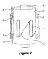
- FIG. 2depicts an exploded view of the sensor arrangement shown in FIG. 2 .
- FIG. 3depicts a cross sectional view of the sensor arrangement shown in FIG. 1 taken perpendicularly to the axis of the casing.
- FIG. 4depicts an embodiment of the present invention wherein an optical fiber sensor is wrapped circumferentially around the casing to detect hoop stresses perpendicular to the axis of the casing.
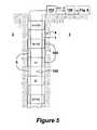
- FIG. 5depicts a casing sensor array comprising a number of sensor stations incorporating the sensors configurations of FIGS. 1-4 , and related optical source/detection and signal processing equipment.
- FIG. 6depicts frequency spectra detectable by the disclosed sensors for a casing without microfracture stresses (top) and with microfracture stresses (bottom).
- the disclosed embodimentsare useful in directly monitoring well casing strain, and particularly when then the strain reaches a level that can threaten the structural integrity of the well casing.
- the disclosed embodimentspreferably use optical fiber sensors, which provide a large number of options for measuring the strain imposed on a well casing and which offers high reliability.
- Fiber optic sensorsalso have the additional benefit that they can be easily multiplexed along a single fiber optic cable (using time division multiplexing or wavelength division multiplexing as is well known) to allow for several sensors to be connected in series, or to be connected to other optical sensors that measure parameters other than casing strain.
- other types of strain-measuring sensorscan be used if desired, such an electrical, piezoelectric, capacitive, accelerometers, etc.
- the magnitude of well casing strain of interest to detectis between about 0.01% and 10.0%, which is believed to equate to stresses ranging from about 3000 pounds per square inch (psi) to well above the yield strength for a standard steel casing. At a 10% axial strain (i.e., parallel to the casing axis), the casing would be expected to undergo significant plastic deformation and possible catastrophic failure.
- the disclosed fiber optic sensorswhich are preferably made of optical fiber having a cladding diameter of from about 80 to 125 microns, can be subject to about 100,000 psi (i.e., 1% strain) along its length without serious risk of breaking, and hence will be able to detect high strains and potential problems up to at least the onset of plastic deformation of steel casings. Therefore, it is theorized that the disclosed fiber optic sensors can be used to detect strains in the casing of between 0.01% and 1.0%, which covers a large portion of the detectable range of interest, and possibly higher ranges when detecting shear stresses which are not aligned with the optical fiber.
- FIGS. 1 to 4disclose preferred embodiments of optical fiber sensors for directly monitoring well casing strain by either measuring static strain or by measuring dynamic acoustic emissions coming from microfractures occurring in the metal structure of the well casing. More specifically, these Figures show a segment of well casing 1 embedded in casing cement 4 , which is further embedded in subsurface formation 3 .
- a production tube 2through which oil flows during production, is located inside of well casing 1 .
- An optical fiber 8extends alongside well casing 1 and is enclosed by protective cable 5 throughout its length. Cable 5 is preferably comprises a 1 ⁇ 4 inch diameter metal tube for housing the fiber optic cable that forms or is spliced or coupled to the fiber optic sensor disclosed herein.
- the cable 5is preferably banded or clamped to the outside of the casing at various points along its length.
- the length of optical fiber 8 that is attached to the exterior surface of well casing 1 to form the sensor(s)is covered by a sensor housing 9 .
- the housingcan be similar in construction to that disclosed in U.S. Pat. No. 6,435,030, which discloses a housing for sensors coupled to the production tube, and which is incorporated by reference in its entirety.
- a housing 9 to protect the sensors outside of the casingconstitutes a novel advance over the prior art disclosed in aforementioned incorporated U.S. patent application Ser. No. 09/612,775 and U.S. Pat. No. 6,435,030.
- the '030 patentdoes not disclose the use of a housing for sensors deployed on the casing.
- fiber optic sensors attached to the casingare not confined within a rigid housing because the goal of that application is to acoustically couple the sensors to the subsurface formation to efficiently detect seismic events.
- the housing 9helps to effectuate this goal.
- Sensor housing 9is preferably welded to the exterior surface of well casing 1 , and covers the entire length of optical fiber 8 that is attached to well casing 1 .
- Sensor housing 9is further preferably vacuumed or filled with an inert gas such as nitrogen to form an acoustically insulative gap between the housing and the sensors (which is helpful even though external borehole noise could to some extent couple through other portions of the casing 1 to the sensors).
- the housing 9 and cable 5are preferably affixed to the casing before it is deployed down hole, and before application of the casing cement.
- Optical fiber 8could be a standard communications fiber, although environmental considerations may dictate the use of fibers that are for instance not sensitive to hydrogen which is often present in the well fluid.
- fiber 8is preferably formed into or spliced to coils 7 which are each bounded by a pair of fiber Bragg gratings (FBGs) 6 to form the casing strain sensors.
- FBGsfiber Bragg gratings
- the use of FBGs in fiber optic sensorsis well known in the art, and the reader is referred to U.S. Pat. Nos. 5,767,411, 5,892,860, 5,986,749, 6,072,567, 6,233,374, and 6,354,147, all of which are incorporated herein by reference, to better understand such applications.
- Each coil 7when unwound, is preferably from approximately 10 to 100 meters in length.
- Coils 7are preferably attached to the exterior surface of well casing 1 with the use of an epoxy or an adhesive film. More specifically, an epoxy film is first adhered to the exterior surface of well casing 1 , and the coils 7 are placed on top of the epoxy film. The epoxy film may then be cured, or heated, to rigidly bond optical fiber to the exterior surface of well casing 1 . When affixing the fiber to the casing, it may be preferably to place the fiber under some amount of tension. In this way, compression of the casing may be more easily detected by assessment of the relaxation of the tensile stress on the fiber 8 .
- sensor coils 7are attached at more than one depth on the well casing 1 (see FIG. 5 ).
- several sensor regionssuch as that depicted in FIG. 1 may be multiplexed along a common fiber optic cable 8 at various depths on the casing.
- the sensorsmay be, for example, time division multiplexed (TDM) or wavelength division multiplexed (WDM), as is well known to those of skill in the art.
- the coils 7are elongated in a direction parallel to the axis, which makes them particularly sensitive to axial strains in the casing 1 .
- the overall length of the coils 7are changed accordingly. This change in length of the coil 7 can be determined by assessing the time it takes light to travel through the coil, which is preferably determined by interferometric means.
- Such optical detection schemesare well known, and are disclosed for example in U.S. patent application Ser. No. 09/726,059, entitled “Method and Apparatus for Interrogating Fiber Optic Sensors,” filed Nov. 29, 2000, or U.S. Pat. Nos. 5,767,411 or 6,354,147, which are incorporated herein by reference.
- each coil 7by bounded by a pair of FBGs 6 , such that each coil's pair has a unique Bragg reflection wavelength. It is further preferable to isolate the FBGs 6 from casing strain, because without such isolation the reflection (Bragg) wavelength of the FBGs might excessively shift, which would make their detection difficult and hence compromise sensor function. In this regard, it can be useful to place an isolation pad between the FBGs 6 and the outside surface of the casing, similar to the method disclosed in U.S. Pat. No. 6,501,067, issued Dec. 31, 2002, and which is incorporated by reference in its entirety. When so configured, the coils may be multiplexed together using a wavelength division multiplexing approach.
- each coil 7can be separated by a single FBG 6 (not shown), wherein each separating FBG has the same Bragg reflection wavelength in a time division multiplexing approach, such as is disclosed in U.S. Pat. No. 6,354,147.
- FBGs 6can be fusion spliced to the coils 7 and to the fiber 8 , which is preferable to reduce signal attenuation as it passes through the various coils. As the details of fusion splicing are well known, they are not repeated here.
- the length of the coils 7 along the axis of the casingcan be easily changed, e.g., up to tens of meters, which allows for static strains along this length to be averaged, which might be suitable in some applications. If a very long strain length measurement is desire, it may not even be necessary to form a coil, and instead sensor 7 can constitute a straight line of fiber optic cable affixed to the exterior of the casing. However, care should be taken to adjust the length of the sensor, be it coiled or uncoiled, so that interferometric detection is possible if an interferometric interrogation scheme is used.
- the coils 7 of FIGS. 1-3are preferably spaced at equal intervals around the outside diameter of the casing, e.g., at 90 degrees when four coils 7 are used. In this manner, the location or distribution of the stress on the casing can be deduced. For example, if the casing is stressed by bending to the right, the coil 7 on the right side might be seen to have compressed (or its relative degree of tensile stress relaxed) while the coil 7 on the left side might be seen to be relatively elongated by tension. Of course, more or fewer than four coils 7 could be used.
- the FBGs 6 themselvesmay act as the sensors.
- the FBGs 6would themselves be attached to the casing at the position of the coils, and would be oriented parallel to the axis of the casing. Axial deformation of the casing will stretch or compress the FBGs 6 , and the amount of deformation can be determined by assessing the shift in the Bragg reflection wavelength of the FBGs, as is well known. If such an alternative approach is used, it would be preferable that each FBG have a unique Bragg reflection wavelength to allow proper resolution of one FBG from another, i.e., in a wavelength division multiplexing approach.
- the FBGs 6 in this approachcan be serpentined around the casing 1 , in a manner similar to that disclosed in U.S. Pat. No. 6,354,147 in order to measure shear strain.
- FIG. 4shows an orientation of a fiber optic sensor for measuring hoop strain in the casing.
- the coil 7is wrapped around and affixed to the circumference of the casing 1 , and again is bounded by a pair of FBGs 6 . So oriented, the coil 7 , will elongate or compress when the casing is subject to a hoop strain. If desirable, the coil 7 in this embodiment may be coiled at an angle around the casing, or may constitute a helical structure, which would be preferred for shear strains.
- the sensorswill function equally well if they are mounted on the interior surface of the casing. Whether to mount the sensors on the interior or exterior surface of the casing 1 would be based on considerations such as the risk to the fiber optic cable during installation as well as the availability of a “wet connect,” which are well known, for the connecting internal sensors to the cable after completion of the casing.
- the disclosed sensorsmay be used to detect static strains in the casing.
- an additionally useful benefitcomes from the ability of the disclosed sensors to detect dynamic strains in the casing, namely, those acoustics emitted from microfractures that occurs within the casing when it is placed under relatively high strains.
- Microfracture acousticswill generally be very sharp in duration and of relatively high frequency content, e.g., in the 10 kilohertz to 1 megahertz range. This allows such acoustics to be easily resolved when compared to other acoustics that are present downhole, such as acoustics present in the fluid being produced through the production pipe 2 .
- microfracture-based acousticsare likely to occur under all modes of casing loading, but with different characteristic signatures of amplitude, frequency content and rate of acoustic events.
- the relatively low energy release of these acoustic emissionspreferably requires a strain sensor that is highly sensitive, such as the interferometric sensor arrangements disclosed above.
- coils 7When detecting microfracture acoustics, axial orientation of coils 7 ( FIGS. 1-3 ) is preferred because acoustic emissions generally propagate axially along the length of well casing 1 .
- coils 7are preferably attached to well casing 1 at a distance away from known zones of high subsurface formation stress if possible so that acoustics can be detected (as they move through the casing) without directly exposing the sensors to the stress. With this offset location, the sensor will be capable of detecting casing strains up to at least 10 percent strain.
- the sensorse.g., coils 7
- the sensorsare adjusted in length to be sensitive to the frequencies and amplitude characteristic of acoustic emissions caused by microfractures in well casing 1 , which may require some experimentation for a given application within the purview of one skilled in the art.
- acoustic emissions from metal structures, such as well casing 1are distinct events that normally have a characteristic high frequency content of between about 10 kilohertz to 1 megahertz. This makes detection of these dynamic events relatively simple. First, monitoring of this frequency range would normally only be indicative of microfractures, and not other acoustics naturally present down hole. Second, that these relatively high frequency events are time limited in duration helps to further verify that microfractures in the casing are being detected. Third, as the acoustics emitted from the microfractures will travel along the casing 1 , their origin can be pinpointed. These points are clarified in subsequent paragraphs.
- FIG. 5shows a system incorporating several casing monitoring sensor stations 100 deployed down hole to form a sensor array.
- Each station 100comprises the sensor embodiments disclosed in FIGS. 1-3 or 4 (or both) and can be multiplexed together along a common fiber optic cable housed in cable 5 as described above.
- the spacing between the sensor stations 100can vary to achieve the desired resolution along the casing, and preferably can range from 50 to 1000 feet in length.
- the arrayis coupled to optical source/detection equipment 110 which usually resides at the surface of the well. Such equipment 110 is well known and not explained further.
- the electronics in equipment 110convert the reflected signals from the various sensors into data constructs indicative of the acoustic strain waves propagating in the casing and straining the sensors as a function of time, again as is well known, and this data is transferred to a signal analysis device 120 .
- the signal analysis device 120converts the strain data into a frequency spectrum, represented in FIG. 6 .
- the frequency spectra of FIG. 6are generated and updated at various times for each sensor in each sensor station 100 in accordance with a sampling rate at which the sensors are interrogated.
- each frequency spectramay be generated and/or updated every 0.05 to 1.0 seconds, or at whatever rate would be necessary to “see” the acoustics emitted from the microfractures, which as noted above are time-limited events.
- dynamics stresses caused by microfractures in the casingare not present, and referring to the top spectrum of FIG. 6 , significant acoustics will not be seen in the 10 kHz to 1 MHz range of interest, although some amount of baseline acoustics may be seen in this range.
- peaks 130will be seen in this range of interest, indicative of the acoustics emitted by these microfractures.
- Such peaks 130can be detected and processed either manually (e.g., visually) or through algorithmic data analysis means.
- the conversion of the strain induced acoustic data from the sensors into its constituent frequency componentsis well known to those in the signal processing arts, this conversion process is only briefly described.
- the reflected signals from the sensors in the sensor stations 100will initially constitute data reflective of the acoustic strain waves presented to the sensor as a function of time.
- This acoustic strain wave versus time datais then transformed by the signal analysis device 120 to provide, for some sampled period, a spectrum of amplitude versus frequency, as is shown in FIG. 6 .
- the disclosed sensorscan detect frequencies up to 1 MHz, and hence should be suitable to detect microfractures in the casing, one skilled in the art will recognize that suitably short sampling periods may be necessary to resolve a particular frequency range of interest. If necessary, the signal analysis device 120 could contain a high pass filter to filter out lower frequencies not of particular interest to the detection of microfracture acoustics.
- the acousticsare detected at each of these two stations pursuant to the frequency analysis technique disclosed above. If not significantly attenuated, the acoustics will then propagate to the next sensor stations.
- the location of the strain that is generating the microfracture acousticsi.e., at location 140 , can be determined, which might allow for inspection of this location or other corrective action.
- This assessmentcan be made before or after converting the time-based acoustic signals to frequency spectra. If time based-acoustic signals are used, well known cross correlation techniques, such as those disclosed in U.S. Pat. No. 6,354,147, can be used to compare the signals at each of the stations and to compare them to understand the relative differences in time that the acoustics arrive at each of the sensor stations.
- the sensing elementsmay comprise accelerometers, such as piezoelectric accelerometers capable of detecting the frequencies of interest.
- accelerometerssuch as piezoelectric accelerometers capable of detecting the frequencies of interest.
- temperature compensation schemesare preferably necessary in conjunction with the disclosed techniques and apparatuses. Such compensation can be necessary to distinguish whether sensor deformation results from stress (e.g., from compression or tension of the sensors) or from temperature (e.g., from thermal expansion of the lengths of the sensors).
- stresse.g., from compression or tension of the sensors
- temperaturee.g., from thermal expansion of the lengths of the sensors.
- an FBG isolated from the casing (and other) strainse.g., can be used to detect the temperature so that the disclosed sensors can be compensated for to understand only the pressures impingent upon them.
- temperature compensation schemes for fiber optic sensorsare well known, and can constitute a myriad of forms, they are not disclosed further.
Landscapes
- Physics & Mathematics (AREA)
- Life Sciences & Earth Sciences (AREA)
- Engineering & Computer Science (AREA)
- Geology (AREA)
- Mining & Mineral Resources (AREA)
- Geophysics (AREA)
- Environmental & Geological Engineering (AREA)
- Fluid Mechanics (AREA)
- General Life Sciences & Earth Sciences (AREA)
- Geochemistry & Mineralogy (AREA)
- Length Measuring Devices By Optical Means (AREA)
Abstract
Description
Claims (33)
Priority Applications (4)
| Application Number | Priority Date | Filing Date | Title |
|---|---|---|---|
| US10/441,233US6957574B2 (en) | 2003-05-19 | 2003-05-19 | Well integrity monitoring system |
| CA2467615ACA2467615C (en) | 2003-05-19 | 2004-05-18 | Well casing integrity monitoring system |
| GB0411168AGB2402478B (en) | 2003-05-19 | 2004-05-19 | Well casing integrity monitoring system |
| PCT/US2004/015602WO2004104372A1 (en) | 2003-05-19 | 2004-05-19 | Well integrity monitoring system |
Applications Claiming Priority (1)
| Application Number | Priority Date | Filing Date | Title |
|---|---|---|---|
| US10/441,233US6957574B2 (en) | 2003-05-19 | 2003-05-19 | Well integrity monitoring system |
Publications (2)
| Publication Number | Publication Date |
|---|---|
| US20040246816A1 US20040246816A1 (en) | 2004-12-09 |
| US6957574B2true US6957574B2 (en) | 2005-10-25 |
Family
ID=32655734
Family Applications (1)
| Application Number | Title | Priority Date | Filing Date |
|---|---|---|---|
| US10/441,233Expired - LifetimeUS6957574B2 (en) | 2003-05-19 | 2003-05-19 | Well integrity monitoring system |
Country Status (4)
| Country | Link |
|---|---|
| US (1) | US6957574B2 (en) |
| CA (1) | CA2467615C (en) |
| GB (1) | GB2402478B (en) |
| WO (1) | WO2004104372A1 (en) |
Cited By (22)
| Publication number | Priority date | Publication date | Assignee | Title |
|---|---|---|---|---|
| US20040112595A1 (en)* | 2002-11-05 | 2004-06-17 | F.X. Bostick | Permanent downhole deployment of optical sensors |
| US20070234789A1 (en)* | 2006-04-05 | 2007-10-11 | Gerard Glasbergen | Fluid distribution determination and optimization with real time temperature measurement |
| US20070289779A1 (en)* | 2006-03-30 | 2007-12-20 | Schlumberger Technology Corporation | Providing a sensor array |
| US20080093069A1 (en)* | 2006-10-20 | 2008-04-24 | O'malley Edward J | Downhole wet connect using piezoelectric contacts |
| WO2007076026A3 (en)* | 2005-12-23 | 2008-06-26 | Quantum Fuel Systems Technolog | Safety warning and shutdown device and method for hydrogen storage containers |
| US20080314577A1 (en)* | 2007-06-19 | 2008-12-25 | Vetco Gray Inc. | Stress, strain and fatigue measuring of well piping |
| US20090151935A1 (en)* | 2007-12-13 | 2009-06-18 | Schlumberger Technology Corporation | System and method for detecting movement in well equipment |
| US20090166042A1 (en)* | 2007-12-28 | 2009-07-02 | Welldynamics, Inc. | Purging of fiber optic conduits in subterranean wells |
| WO2010025159A1 (en)* | 2008-08-27 | 2010-03-04 | Shell Oil Company | Monitoring system for well casing |
| US20110102766A1 (en)* | 2009-11-02 | 2011-05-05 | Honda Motor Co., Ltd. | Optical fiber sensor, pressure sensor, end effector and stress detecting method using the same |
| US20120024052A1 (en)* | 2008-12-02 | 2012-02-02 | Egil Eriksen | downhole pressure and vibration measuring device integrated in a pipe section as a part of a production tubing |
| US8215164B1 (en)* | 2012-01-02 | 2012-07-10 | HydroConfidence Inc. | Systems and methods for monitoring groundwater, rock, and casing for production flow and leakage of hydrocarbon fluids |
| US8505625B2 (en) | 2010-06-16 | 2013-08-13 | Halliburton Energy Services, Inc. | Controlling well operations based on monitored parameters of cement health |
| US8636063B2 (en) | 2011-02-16 | 2014-01-28 | Halliburton Energy Services, Inc. | Cement slurry monitoring |
| US9075155B2 (en) | 2011-04-08 | 2015-07-07 | Halliburton Energy Services, Inc. | Optical fiber based downhole seismic sensor systems and methods |
| US9127532B2 (en) | 2011-09-07 | 2015-09-08 | Halliburton Energy Services, Inc. | Optical casing collar locator systems and methods |
| US9127531B2 (en) | 2011-09-07 | 2015-09-08 | Halliburton Energy Services, Inc. | Optical casing collar locator systems and methods |
| US9297767B2 (en) | 2011-10-05 | 2016-03-29 | Halliburton Energy Services, Inc. | Downhole species selective optical fiber sensor systems and methods |
| US9388686B2 (en) | 2010-01-13 | 2016-07-12 | Halliburton Energy Services, Inc. | Maximizing hydrocarbon production while controlling phase behavior or precipitation of reservoir impairing liquids or solids |
| US9874432B2 (en) | 2010-08-19 | 2018-01-23 | Halliburton Energy Services, Inc | Optical pressure sensor |
| US10060250B2 (en) | 2012-03-13 | 2018-08-28 | Halliburton Energy Services, Inc. | Downhole systems and methods for water source determination |
| US10202821B2 (en)* | 2013-08-30 | 2019-02-12 | Statoil Petroleum As | Method of plugging a well |
Families Citing this family (30)
| Publication number | Priority date | Publication date | Assignee | Title |
|---|---|---|---|---|
| BRPI0619501A2 (en)* | 2005-12-09 | 2011-10-04 | Sabeus Inc | high density fiber optic acoustic arrangement |
| US7683312B2 (en) | 2007-10-23 | 2010-03-23 | Us Sensor Systems, Inc. | Fiber-optic interrogator with normalization filters |
| GB2454220B (en)* | 2007-11-01 | 2012-05-23 | Schlumberger Holdings | Apparatus and methods for detecting strain in structures |
| US8635907B2 (en)* | 2007-11-30 | 2014-01-28 | Shell Oil Company | Real-time completion monitoring with acoustic waves |
| CA2732894C (en)* | 2008-08-07 | 2016-01-26 | Sensornet Limited | Fiber splice housing |
| US20100303426A1 (en)* | 2009-05-29 | 2010-12-02 | Baker Hughes Incorporated | Downhole optical fiber spice housing |
| US9194738B2 (en) | 2009-10-23 | 2015-11-24 | Pacific Western Bank | Fiber optic microseismic sensing systems |
| GB0919904D0 (en)* | 2009-11-13 | 2009-12-30 | Qinetiq Ltd | Determining lateral offset in distributed fibre optic acoustic sensing |
| WO2011103271A2 (en) | 2010-02-18 | 2011-08-25 | US Seismic Systems, Inc. | Fiber optic personnel safety systems and methods of using the same |
| US9158032B2 (en) | 2010-02-18 | 2015-10-13 | US Seismic Systems, Inc. | Optical detection systems and methods of using the same |
| US8401354B2 (en) | 2010-02-23 | 2013-03-19 | US Seismic Systems, Inc. | Fiber optic security systems and methods of using the same |
| US8701481B2 (en) | 2010-07-06 | 2014-04-22 | US Seismic Systems, Inc. | Borehole sensing and clamping systems and methods of using the same |
| WO2012103085A2 (en) | 2011-01-25 | 2012-08-02 | US Seismic Systems, Inc. | Light powered communication systems and methods of using the same |
| US9217801B2 (en) | 2011-03-08 | 2015-12-22 | Pacific Western Bank | Fiber optic acoustic sensor arrays and systems, and methods of fabricating the same |
| GB201109372D0 (en)* | 2011-06-06 | 2011-07-20 | Silixa Ltd | Method for locating an acoustic source |
| WO2014018959A1 (en) | 2012-07-27 | 2014-01-30 | US Seismic Systems, Inc. | Remotely actuated clamping devices for borehole seismic sensing systems and methods of operating the same |
| US9416652B2 (en) | 2013-08-08 | 2016-08-16 | Vetco Gray Inc. | Sensing magnetized portions of a wellhead system to monitor fatigue loading |
| CN103673895B (en)* | 2013-11-29 | 2016-05-11 | 华中科技大学 | Fiber Bragg Grating FBG micro-displacement sensor and measuring method thereof |
| CN103615210B (en)* | 2013-12-06 | 2016-03-30 | 西安石油大学 | A kind of Fibre Optical Sensor is with brill downhole device |
| WO2016061171A1 (en)* | 2014-10-15 | 2016-04-21 | Schlumberger Canada Limited | Borehole casing deployment detection |
| US20180274357A1 (en)* | 2015-11-02 | 2018-09-27 | Halliburton Energy Services, Inc. | High-Resolution-Molded Mandrel |
| CN109322661A (en)* | 2017-07-28 | 2019-02-12 | 中国石油天然气股份有限公司 | Method and device for checking strength of casing |
| CN109813473B (en)* | 2019-03-18 | 2020-11-17 | 南开大学 | Four-dimensional force sensor of minimally invasive surgical robot based on fiber bragg grating |
| CN110031553B (en)* | 2019-05-17 | 2021-07-27 | 西南石油大学 | Casing damage monitoring system and method |
| US12247478B2 (en) | 2020-03-11 | 2025-03-11 | Conocophillips Company | Management of subsea wellhead stresses |
| CN112253092B (en)* | 2020-09-18 | 2023-11-07 | 中国电建集团中南勘测设计研究院有限公司 | Device and method for measuring gradient of deepwater drilling riser |
| GB2603205A (en)* | 2021-02-02 | 2022-08-03 | Focus Sensors Ltd | Ground sensing utlising active sources |
| CN113587890B (en)* | 2021-08-02 | 2022-08-19 | 安徽理工大学 | Multisource data mining area earth surface deformation early warning platform |
| CN115704315B (en)* | 2021-08-11 | 2025-05-13 | 中国石油化工股份有限公司 | A system and method for testing wellbore sealing integrity |
| CN116295084B (en)* | 2023-05-19 | 2023-08-08 | 合肥小步智能科技有限公司 | Underground coal mine vertical shaft inspection robot |
Citations (64)
| Publication number | Priority date | Publication date | Assignee | Title |
|---|---|---|---|---|
| US2846662A (en) | 1955-10-17 | 1958-08-05 | Pan American Petroleum Corp | Receiving seismic waves directionally |
| US4360272A (en) | 1980-03-20 | 1982-11-23 | Optelecom, Inc. | Fiber optic energy sensor and optical demodulation system and methods of making same |
| US4589285A (en) | 1984-11-05 | 1986-05-20 | Western Geophysical Co. Of America | Wavelength-division-multiplexed receiver array for vertical seismic profiling |
| US4649529A (en) | 1985-12-02 | 1987-03-10 | Exxon Production Research Co. | Multi-channel fiber optic sensor system |
| US4654520A (en) | 1981-08-24 | 1987-03-31 | Griffiths Richard W | Structural monitoring system using fiber optics |
| US4745293A (en) | 1987-03-23 | 1988-05-17 | Cv Technology, Inc. | Method and apparatus for optically measuring fluid levels |
| US4761073A (en) | 1984-08-13 | 1988-08-02 | United Technologies Corporation | Distributed, spatially resolving optical fiber strain gauge |
| US4806012A (en) | 1984-08-13 | 1989-02-21 | United Technologies Corporation | Distributed, spatially resolving optical fiber strain gauge |
| US4825424A (en) | 1985-10-21 | 1989-04-25 | Plessey Overseas Limited | Sensing systems |
| US4898236A (en) | 1986-03-07 | 1990-02-06 | Downhole Systems Technology Canada | Drill stem testing system |
| US4950883A (en) | 1988-12-27 | 1990-08-21 | United Technologies Corporation | Fiber optic sensor arrangement having reflective gratings responsive to particular wavelengths |
| US4996419A (en) | 1989-12-26 | 1991-02-26 | United Technologies Corporation | Distributed multiplexed optical fiber Bragg grating sensor arrangeement |
| US5012088A (en) | 1989-03-31 | 1991-04-30 | Cole James H | High performance fiber optic sensor |
| US5051965A (en) | 1985-04-19 | 1991-09-24 | Western Atlas International, Inc. | Acousto-optical marine sensor array |
| US5111903A (en) | 1988-09-21 | 1992-05-12 | Institut Francais Du Petrole | Signal receiving system able to be coupled with the wall of a well or drilling |
| US5163321A (en) | 1989-10-17 | 1992-11-17 | Baroid Technology, Inc. | Borehole pressure and temperature measurement system |
| US5308973A (en) | 1990-11-22 | 1994-05-03 | Hilti Aktiengesellschaft | Method and device for the measurement of force by a fiber optics system by evaluating phase shift of light waves |
| US5317383A (en) | 1992-09-18 | 1994-05-31 | Shell Oil Company | Array retroreflector apparatus for remote seismic sensing |
| US5319435A (en) | 1991-09-04 | 1994-06-07 | Melle Serge M | Method and apparatus for measuring the wavelength of spectrally narrow optical signals |
| US5327216A (en) | 1992-09-18 | 1994-07-05 | Shell Oil Company | Apparatus for remote seismic sensing of array signals using side-by-side retroreflectors |
| US5339696A (en) | 1993-03-31 | 1994-08-23 | Advanced Mechanical Technology, Inc. | Bolt torque and tension transducer |
| US5353637A (en) | 1992-06-09 | 1994-10-11 | Plumb Richard A | Methods and apparatus for borehole measurement of formation stress |
| US5361130A (en) | 1992-11-04 | 1994-11-01 | The United States Of America As Represented By The Secretary Of The Navy | Fiber grating-based sensing system with interferometric wavelength-shift detection |
| US5380995A (en) | 1992-10-20 | 1995-01-10 | Mcdonnell Douglas Corporation | Fiber optic grating sensor systems for sensing environmental effects |
| US5397891A (en) | 1992-10-20 | 1995-03-14 | Mcdonnell Douglas Corporation | Sensor systems employing optical fiber gratings |
| US5401956A (en) | 1993-09-29 | 1995-03-28 | United Technologies Corporation | Diagnostic system for fiber grating sensors |
| GB2284256A (en) | 1993-11-26 | 1995-05-31 | Sensor Dynamics Ltd | Wavelength addressed network of fibre optic interferometric sensors |
| US5426297A (en) | 1993-09-27 | 1995-06-20 | United Technologies Corporation | Multiplexed Bragg grating sensors |
| US5444803A (en) | 1993-04-24 | 1995-08-22 | Agency Of Defense Development | Fiber-optic devices and sensors using fiber grating |
| US5452087A (en) | 1993-11-04 | 1995-09-19 | The Texas A & M University System | Method and apparatus for measuring pressure with embedded non-intrusive fiber optics |
| US5451772A (en) | 1994-01-13 | 1995-09-19 | Mechanical Technology Incorporated | Distributed fiber optic sensor |
| US5493113A (en) | 1994-11-29 | 1996-02-20 | United Technologies Corporation | Highly sensitive optical fiber cavity coating removal detection |
| US5493390A (en) | 1993-09-06 | 1996-02-20 | Finmeccanica S.P.A.-Ramo Aziendale Alenia | Integrated optical instrumentation for the diagnostics of parts by embedded or surface attached optical sensors |
| US5495892A (en) | 1993-12-30 | 1996-03-05 | Carisella; James V. | Inflatable packer device and method |
| US5497233A (en) | 1994-07-27 | 1996-03-05 | Litton Systems, Inc. | Optical waveguide vibration sensor and method |
| US5507341A (en) | 1994-12-22 | 1996-04-16 | Dowell, A Division Of Schlumberger Technology Corp. | Inflatable packer with bladder shape control |
| US5513913A (en) | 1993-01-29 | 1996-05-07 | United Technologies Corporation | Active multipoint fiber laser sensor |
| US5529346A (en) | 1992-11-10 | 1996-06-25 | Intellectual Property Holdings Pte Limited | Joints |
| US5564504A (en) | 1993-12-30 | 1996-10-15 | Carisella; James V. | Programmed shape inflatable packer device and method |
| US5636021A (en) | 1995-06-02 | 1997-06-03 | Udd; Eric | Sagnac/Michelson distributed sensing systems |
| US5675674A (en) | 1995-08-24 | 1997-10-07 | Rockbit International | Optical fiber modulation and demodulation system |
| US5680489A (en) | 1996-06-28 | 1997-10-21 | The United States Of America As Represented By The Secretary Of The Navy | Optical sensor system utilizing bragg grating sensors |
| US5767411A (en) | 1996-12-31 | 1998-06-16 | Cidra Corporation | Apparatus for enhancing strain in intrinsic fiber optic sensors and packaging same for harsh environments |
| US5789669A (en) | 1997-08-13 | 1998-08-04 | Flaum; Charles | Method and apparatus for determining formation pressure |
| US5804713A (en) | 1994-09-21 | 1998-09-08 | Sensor Dynamics Ltd. | Apparatus for sensor installations in wells |
| US5892860A (en) | 1997-01-21 | 1999-04-06 | Cidra Corporation | Multi-parameter fiber optic sensor for use in harsh environments |
| US5925879A (en) | 1997-05-09 | 1999-07-20 | Cidra Corporation | Oil and gas well packer having fiber optic Bragg Grating sensors for downhole insitu inflation monitoring |
| US5986749A (en) | 1997-09-19 | 1999-11-16 | Cidra Corporation | Fiber optic sensing system |
| US5987197A (en) | 1997-11-07 | 1999-11-16 | Cidra Corporation | Array topologies for implementing serial fiber Bragg grating interferometer arrays |
| US6016702A (en) | 1997-09-08 | 2000-01-25 | Cidra Corporation | High sensitivity fiber optic pressure sensor for use in harsh environments |
| US6072567A (en) | 1997-02-12 | 2000-06-06 | Cidra Corporation | Vertical seismic profiling system having vertical seismic profiling optical signal processing equipment and fiber Bragg grafting optical sensors |
| US6175108B1 (en) | 1998-01-30 | 2001-01-16 | Cidra Corporation | Accelerometer featuring fiber optic bragg grating sensor for providing multiplexed multi-axis acceleration sensing |
| GB2354782A (en) | 1999-08-17 | 2001-04-04 | Baker Hughes Inc | Fibre optic monitoring of sand control equipment |
| US6233374B1 (en) | 1999-06-04 | 2001-05-15 | Cidra Corporation | Mandrel-wound fiber optic pressure sensor |
| US6233746B1 (en)* | 1999-03-22 | 2001-05-22 | Halliburton Energy Services, Inc. | Multiplexed fiber optic transducer for use in a well and method |
| US6268911B1 (en)* | 1997-05-02 | 2001-07-31 | Baker Hughes Incorporated | Monitoring of downhole parameters and tools utilizing fiber optics |
| US6354147B1 (en) | 1998-06-26 | 2002-03-12 | Cidra Corporation | Fluid parameter measurement in pipes using acoustic pressures |
| US20020041722A1 (en) | 2000-08-01 | 2002-04-11 | Johnson Gregg A. | Optical sensing device containing fiber bragg gratings |
| GB2367890A (en) | 2000-10-06 | 2002-04-17 | Abb Offshore Systems Ltd | Sensing strain in hydrocarbon wells |
| US6384919B1 (en) | 1999-10-29 | 2002-05-07 | Northrop Grumman Corporation | Fiber optic seismic sensor |
| WO2002057805A2 (en) | 2000-06-29 | 2002-07-25 | Tubel Paulo S | Method and system for monitoring smart structures utilizing distributed optical sensors |
| US6435030B1 (en) | 1999-06-25 | 2002-08-20 | Weatherford/Lamb, Inc. | Measurement of propagating acoustic waves in compliant pipes |
| US6501067B2 (en) | 2000-11-29 | 2002-12-31 | Weatherford/Lamb, Inc. | Isolation pad for protecting sensing devices on the outside of a conduit |
| US6840114B2 (en)* | 2003-05-19 | 2005-01-11 | Weatherford/Lamb, Inc. | Housing on the exterior of a well casing for optical fiber sensors |
Family Cites Families (1)
| Publication number | Priority date | Publication date | Assignee | Title |
|---|---|---|---|---|
| CA2085017C (en)* | 1992-12-10 | 1999-01-05 | Benoit Ludger Beaulieu | Damper for a grapple |
- 2003
- 2003-05-19USUS10/441,233patent/US6957574B2/ennot_activeExpired - Lifetime
- 2004
- 2004-05-18CACA2467615Apatent/CA2467615C/ennot_activeExpired - Fee Related
- 2004-05-19GBGB0411168Apatent/GB2402478B/ennot_activeExpired - Fee Related
- 2004-05-19WOPCT/US2004/015602patent/WO2004104372A1/enactiveApplication Filing
Patent Citations (64)
| Publication number | Priority date | Publication date | Assignee | Title |
|---|---|---|---|---|
| US2846662A (en) | 1955-10-17 | 1958-08-05 | Pan American Petroleum Corp | Receiving seismic waves directionally |
| US4360272A (en) | 1980-03-20 | 1982-11-23 | Optelecom, Inc. | Fiber optic energy sensor and optical demodulation system and methods of making same |
| US4654520A (en) | 1981-08-24 | 1987-03-31 | Griffiths Richard W | Structural monitoring system using fiber optics |
| US4806012A (en) | 1984-08-13 | 1989-02-21 | United Technologies Corporation | Distributed, spatially resolving optical fiber strain gauge |
| US4761073A (en) | 1984-08-13 | 1988-08-02 | United Technologies Corporation | Distributed, spatially resolving optical fiber strain gauge |
| US4589285A (en) | 1984-11-05 | 1986-05-20 | Western Geophysical Co. Of America | Wavelength-division-multiplexed receiver array for vertical seismic profiling |
| US5051965A (en) | 1985-04-19 | 1991-09-24 | Western Atlas International, Inc. | Acousto-optical marine sensor array |
| US4825424A (en) | 1985-10-21 | 1989-04-25 | Plessey Overseas Limited | Sensing systems |
| US4649529A (en) | 1985-12-02 | 1987-03-10 | Exxon Production Research Co. | Multi-channel fiber optic sensor system |
| US4898236A (en) | 1986-03-07 | 1990-02-06 | Downhole Systems Technology Canada | Drill stem testing system |
| US4745293A (en) | 1987-03-23 | 1988-05-17 | Cv Technology, Inc. | Method and apparatus for optically measuring fluid levels |
| US5111903A (en) | 1988-09-21 | 1992-05-12 | Institut Francais Du Petrole | Signal receiving system able to be coupled with the wall of a well or drilling |
| US4950883A (en) | 1988-12-27 | 1990-08-21 | United Technologies Corporation | Fiber optic sensor arrangement having reflective gratings responsive to particular wavelengths |
| US5012088A (en) | 1989-03-31 | 1991-04-30 | Cole James H | High performance fiber optic sensor |
| US5163321A (en) | 1989-10-17 | 1992-11-17 | Baroid Technology, Inc. | Borehole pressure and temperature measurement system |
| US4996419A (en) | 1989-12-26 | 1991-02-26 | United Technologies Corporation | Distributed multiplexed optical fiber Bragg grating sensor arrangeement |
| US5308973A (en) | 1990-11-22 | 1994-05-03 | Hilti Aktiengesellschaft | Method and device for the measurement of force by a fiber optics system by evaluating phase shift of light waves |
| US5319435A (en) | 1991-09-04 | 1994-06-07 | Melle Serge M | Method and apparatus for measuring the wavelength of spectrally narrow optical signals |
| US5353637A (en) | 1992-06-09 | 1994-10-11 | Plumb Richard A | Methods and apparatus for borehole measurement of formation stress |
| US5327216A (en) | 1992-09-18 | 1994-07-05 | Shell Oil Company | Apparatus for remote seismic sensing of array signals using side-by-side retroreflectors |
| US5317383A (en) | 1992-09-18 | 1994-05-31 | Shell Oil Company | Array retroreflector apparatus for remote seismic sensing |
| US5380995A (en) | 1992-10-20 | 1995-01-10 | Mcdonnell Douglas Corporation | Fiber optic grating sensor systems for sensing environmental effects |
| US5397891A (en) | 1992-10-20 | 1995-03-14 | Mcdonnell Douglas Corporation | Sensor systems employing optical fiber gratings |
| US5361130A (en) | 1992-11-04 | 1994-11-01 | The United States Of America As Represented By The Secretary Of The Navy | Fiber grating-based sensing system with interferometric wavelength-shift detection |
| US5529346A (en) | 1992-11-10 | 1996-06-25 | Intellectual Property Holdings Pte Limited | Joints |
| US5513913A (en) | 1993-01-29 | 1996-05-07 | United Technologies Corporation | Active multipoint fiber laser sensor |
| US5339696A (en) | 1993-03-31 | 1994-08-23 | Advanced Mechanical Technology, Inc. | Bolt torque and tension transducer |
| US5444803A (en) | 1993-04-24 | 1995-08-22 | Agency Of Defense Development | Fiber-optic devices and sensors using fiber grating |
| US5493390A (en) | 1993-09-06 | 1996-02-20 | Finmeccanica S.P.A.-Ramo Aziendale Alenia | Integrated optical instrumentation for the diagnostics of parts by embedded or surface attached optical sensors |
| US5426297A (en) | 1993-09-27 | 1995-06-20 | United Technologies Corporation | Multiplexed Bragg grating sensors |
| US5401956A (en) | 1993-09-29 | 1995-03-28 | United Technologies Corporation | Diagnostic system for fiber grating sensors |
| US5452087A (en) | 1993-11-04 | 1995-09-19 | The Texas A & M University System | Method and apparatus for measuring pressure with embedded non-intrusive fiber optics |
| GB2284256A (en) | 1993-11-26 | 1995-05-31 | Sensor Dynamics Ltd | Wavelength addressed network of fibre optic interferometric sensors |
| US5495892A (en) | 1993-12-30 | 1996-03-05 | Carisella; James V. | Inflatable packer device and method |
| US5564504A (en) | 1993-12-30 | 1996-10-15 | Carisella; James V. | Programmed shape inflatable packer device and method |
| US5451772A (en) | 1994-01-13 | 1995-09-19 | Mechanical Technology Incorporated | Distributed fiber optic sensor |
| US5497233A (en) | 1994-07-27 | 1996-03-05 | Litton Systems, Inc. | Optical waveguide vibration sensor and method |
| US5804713A (en) | 1994-09-21 | 1998-09-08 | Sensor Dynamics Ltd. | Apparatus for sensor installations in wells |
| US5493113A (en) | 1994-11-29 | 1996-02-20 | United Technologies Corporation | Highly sensitive optical fiber cavity coating removal detection |
| US5507341A (en) | 1994-12-22 | 1996-04-16 | Dowell, A Division Of Schlumberger Technology Corp. | Inflatable packer with bladder shape control |
| US5636021A (en) | 1995-06-02 | 1997-06-03 | Udd; Eric | Sagnac/Michelson distributed sensing systems |
| US5675674A (en) | 1995-08-24 | 1997-10-07 | Rockbit International | Optical fiber modulation and demodulation system |
| US5680489A (en) | 1996-06-28 | 1997-10-21 | The United States Of America As Represented By The Secretary Of The Navy | Optical sensor system utilizing bragg grating sensors |
| US5767411A (en) | 1996-12-31 | 1998-06-16 | Cidra Corporation | Apparatus for enhancing strain in intrinsic fiber optic sensors and packaging same for harsh environments |
| US5892860A (en) | 1997-01-21 | 1999-04-06 | Cidra Corporation | Multi-parameter fiber optic sensor for use in harsh environments |
| US6072567A (en) | 1997-02-12 | 2000-06-06 | Cidra Corporation | Vertical seismic profiling system having vertical seismic profiling optical signal processing equipment and fiber Bragg grafting optical sensors |
| US6268911B1 (en)* | 1997-05-02 | 2001-07-31 | Baker Hughes Incorporated | Monitoring of downhole parameters and tools utilizing fiber optics |
| US5925879A (en) | 1997-05-09 | 1999-07-20 | Cidra Corporation | Oil and gas well packer having fiber optic Bragg Grating sensors for downhole insitu inflation monitoring |
| US5789669A (en) | 1997-08-13 | 1998-08-04 | Flaum; Charles | Method and apparatus for determining formation pressure |
| US6016702A (en) | 1997-09-08 | 2000-01-25 | Cidra Corporation | High sensitivity fiber optic pressure sensor for use in harsh environments |
| US5986749A (en) | 1997-09-19 | 1999-11-16 | Cidra Corporation | Fiber optic sensing system |
| US5987197A (en) | 1997-11-07 | 1999-11-16 | Cidra Corporation | Array topologies for implementing serial fiber Bragg grating interferometer arrays |
| US6175108B1 (en) | 1998-01-30 | 2001-01-16 | Cidra Corporation | Accelerometer featuring fiber optic bragg grating sensor for providing multiplexed multi-axis acceleration sensing |
| US6354147B1 (en) | 1998-06-26 | 2002-03-12 | Cidra Corporation | Fluid parameter measurement in pipes using acoustic pressures |
| US6233746B1 (en)* | 1999-03-22 | 2001-05-22 | Halliburton Energy Services, Inc. | Multiplexed fiber optic transducer for use in a well and method |
| US6233374B1 (en) | 1999-06-04 | 2001-05-15 | Cidra Corporation | Mandrel-wound fiber optic pressure sensor |
| US6435030B1 (en) | 1999-06-25 | 2002-08-20 | Weatherford/Lamb, Inc. | Measurement of propagating acoustic waves in compliant pipes |
| GB2354782A (en) | 1999-08-17 | 2001-04-04 | Baker Hughes Inc | Fibre optic monitoring of sand control equipment |
| US6384919B1 (en) | 1999-10-29 | 2002-05-07 | Northrop Grumman Corporation | Fiber optic seismic sensor |
| WO2002057805A2 (en) | 2000-06-29 | 2002-07-25 | Tubel Paulo S | Method and system for monitoring smart structures utilizing distributed optical sensors |
| US20020041722A1 (en) | 2000-08-01 | 2002-04-11 | Johnson Gregg A. | Optical sensing device containing fiber bragg gratings |
| GB2367890A (en) | 2000-10-06 | 2002-04-17 | Abb Offshore Systems Ltd | Sensing strain in hydrocarbon wells |
| US6501067B2 (en) | 2000-11-29 | 2002-12-31 | Weatherford/Lamb, Inc. | Isolation pad for protecting sensing devices on the outside of a conduit |
| US6840114B2 (en)* | 2003-05-19 | 2005-01-11 | Weatherford/Lamb, Inc. | Housing on the exterior of a well casing for optical fiber sensors |
Non-Patent Citations (6)
| Title |
|---|
| Gai, H., et al., "Monitoring and Analysis of ECP Inflation Status Memory Gauge Date", SPE #36949 (Oct. 22, 1996), pp. 679-685. |
| Morey, W.W.; Meltz, G.; and Weiss, J.M., "High Temperature Capabilities and Limitations of Fiber Grating Sensors", Proceedings of the SPIE, Tenth International Conference on Optical Fibre Sensors, vol. 2360 (Oct. 11, 1994), pp. 234-237. |
| PCT Search Report, International Application No. PCT/US2004/015602, dated Sep. 6, 2004. |
| U.K. Search Report, Application No. GB0411168.8, dated Oct. 1, 2004. |
| U.S. Appl. No. 09/612,775, entitled "Method and Apparatus for Seismically Surveying an Earth Formation in Relation to a Borehole", filed Jul. 10, 2000. |
| Xu, M.G.; Geiger, H.; and Dakin, J.P., "Fiber Grating Pressure Sensor with Enhanced Sensitivity Using a Glass-Bubble Housing", Electronics Letters, vol. 32, No. 2 (Jan. 18, 1996), pp. 128-129. |
Cited By (42)
| Publication number | Priority date | Publication date | Assignee | Title |
|---|---|---|---|---|
| US7997340B2 (en) | 2002-11-05 | 2011-08-16 | Weatherford/Lamb, Inc. | Permanent downhole deployment of optical sensors |
| US7219729B2 (en)* | 2002-11-05 | 2007-05-22 | Weatherford/Lamb, Inc. | Permanent downhole deployment of optical sensors |
| US20100078164A1 (en)* | 2002-11-05 | 2010-04-01 | Bostick Iii Francis X | Permanent downhole deployment of optical sensors |
| US20040112595A1 (en)* | 2002-11-05 | 2004-06-17 | F.X. Bostick | Permanent downhole deployment of optical sensors |
| WO2007076026A3 (en)* | 2005-12-23 | 2008-06-26 | Quantum Fuel Systems Technolog | Safety warning and shutdown device and method for hydrogen storage containers |
| US20070289779A1 (en)* | 2006-03-30 | 2007-12-20 | Schlumberger Technology Corporation | Providing a sensor array |
| US7836959B2 (en) | 2006-03-30 | 2010-11-23 | Schlumberger Technology Corporation | Providing a sensor array |
| US20070234789A1 (en)* | 2006-04-05 | 2007-10-11 | Gerard Glasbergen | Fluid distribution determination and optimization with real time temperature measurement |
| US7475734B2 (en)* | 2006-10-20 | 2009-01-13 | Baker Hughes Incorporated | Downhole wet connect using piezoelectric contacts |
| US20080093069A1 (en)* | 2006-10-20 | 2008-04-24 | O'malley Edward J | Downhole wet connect using piezoelectric contacts |
| GB2459390A (en)* | 2006-11-09 | 2009-10-28 | Schlumberger Holdings | Providing a sensor array |
| GB2459390B (en)* | 2006-11-09 | 2011-12-14 | Schlumberger Holdings | Providing a sensor array |
| WO2008060769A3 (en)* | 2006-11-09 | 2008-07-10 | Schlumberger Ca Ltd | Providing a sensor array |
| US20080314577A1 (en)* | 2007-06-19 | 2008-12-25 | Vetco Gray Inc. | Stress, strain and fatigue measuring of well piping |
| US7819182B2 (en)* | 2007-06-19 | 2010-10-26 | Vetco Gray Inc. | Stress, strain and fatigue measuring of well piping |
| US20090151935A1 (en)* | 2007-12-13 | 2009-06-18 | Schlumberger Technology Corporation | System and method for detecting movement in well equipment |
| US20090166042A1 (en)* | 2007-12-28 | 2009-07-02 | Welldynamics, Inc. | Purging of fiber optic conduits in subterranean wells |
| US8090227B2 (en) | 2007-12-28 | 2012-01-03 | Halliburton Energy Services, Inc. | Purging of fiber optic conduits in subterranean wells |
| US10221677B2 (en) | 2007-12-28 | 2019-03-05 | Halliburton Energy Services, Inc. | Purging of Fiber Optic Conduits in Subterranean Wells |
| US8973434B2 (en) | 2008-08-27 | 2015-03-10 | Shell Oil Company | Monitoring system for well casing |
| US20110185807A1 (en)* | 2008-08-27 | 2011-08-04 | Shell Internationale Research Maatschappij B.V. | Monitoring system for well casing |
| GB2474996A (en)* | 2008-08-27 | 2011-05-04 | Shell Int Research | Monitoring system for well casing |
| WO2010025159A1 (en)* | 2008-08-27 | 2010-03-04 | Shell Oil Company | Monitoring system for well casing |
| AU2009285803B2 (en)* | 2008-08-27 | 2012-04-19 | Shell Internationale Research Maatschappij B.V. | Monitoring system for well casing |
| US9574434B2 (en) | 2008-08-27 | 2017-02-21 | Shell Oil Company | Monitoring system for well casing |
| GB2474996B (en)* | 2008-08-27 | 2012-12-05 | Shell Int Research | Monitoring system for well casing |
| US8701480B2 (en)* | 2008-12-02 | 2014-04-22 | Tool-Tech As | Downhole pressure and vibration measuring device integrated in a pipe section as a part of a production tubing |
| US20120024052A1 (en)* | 2008-12-02 | 2012-02-02 | Egil Eriksen | downhole pressure and vibration measuring device integrated in a pipe section as a part of a production tubing |
| US8654317B2 (en)* | 2009-11-02 | 2014-02-18 | Honda Motor Co., Ltd. | Optical fiber sensor, pressure sensor, end effector and stress detecting method using the same |
| US20110102766A1 (en)* | 2009-11-02 | 2011-05-05 | Honda Motor Co., Ltd. | Optical fiber sensor, pressure sensor, end effector and stress detecting method using the same |
| US9388686B2 (en) | 2010-01-13 | 2016-07-12 | Halliburton Energy Services, Inc. | Maximizing hydrocarbon production while controlling phase behavior or precipitation of reservoir impairing liquids or solids |
| US8505625B2 (en) | 2010-06-16 | 2013-08-13 | Halliburton Energy Services, Inc. | Controlling well operations based on monitored parameters of cement health |
| US9874432B2 (en) | 2010-08-19 | 2018-01-23 | Halliburton Energy Services, Inc | Optical pressure sensor |
| US8636063B2 (en) | 2011-02-16 | 2014-01-28 | Halliburton Energy Services, Inc. | Cement slurry monitoring |
| US9075155B2 (en) | 2011-04-08 | 2015-07-07 | Halliburton Energy Services, Inc. | Optical fiber based downhole seismic sensor systems and methods |
| US9127531B2 (en) | 2011-09-07 | 2015-09-08 | Halliburton Energy Services, Inc. | Optical casing collar locator systems and methods |
| US9127532B2 (en) | 2011-09-07 | 2015-09-08 | Halliburton Energy Services, Inc. | Optical casing collar locator systems and methods |
| US9297767B2 (en) | 2011-10-05 | 2016-03-29 | Halliburton Energy Services, Inc. | Downhole species selective optical fiber sensor systems and methods |
| US8215164B1 (en)* | 2012-01-02 | 2012-07-10 | HydroConfidence Inc. | Systems and methods for monitoring groundwater, rock, and casing for production flow and leakage of hydrocarbon fluids |
| US10060250B2 (en) | 2012-03-13 | 2018-08-28 | Halliburton Energy Services, Inc. | Downhole systems and methods for water source determination |
| US10202821B2 (en)* | 2013-08-30 | 2019-02-12 | Statoil Petroleum As | Method of plugging a well |
| US10865619B2 (en) | 2013-08-30 | 2020-12-15 | Statoil Petroleum As | Method of plugging a well |
Also Published As
| Publication number | Publication date |
|---|---|
| WO2004104372A1 (en) | 2004-12-02 |
| US20040246816A1 (en) | 2004-12-09 |
| CA2467615A1 (en) | 2004-11-19 |
| GB2402478A (en) | 2004-12-08 |
| GB0411168D0 (en) | 2004-06-23 |
| CA2467615C (en) | 2011-08-02 |
| GB2402478B (en) | 2006-05-17 |
Similar Documents
| Publication | Publication Date | Title |
|---|---|---|
| US6957574B2 (en) | Well integrity monitoring system | |
| US6840114B2 (en) | Housing on the exterior of a well casing for optical fiber sensors | |
| CA2455304C (en) | System and method for monitoring performance of downhole equipment using fiber optic based sensors | |
| JP4774184B2 (en) | Seismic exploration method and seismic exploration device for soil structure in borehole | |
| AU777802B2 (en) | Highly sensitive accelerometer | |
| CA2461437C (en) | Pressure compensated hydrophone | |
| US10472947B2 (en) | Deformation measurement method and apparatus | |
| US6891621B2 (en) | Highly sensitive cross axis accelerometer | |
| GB2510996B (en) | Detecting broadside acoustic signals with a fiber optical distributed acoustic sensing (das) assembly | |
| CA2422037C (en) | Apparatus for acoustic detection of particles in a flow using a fibre optic interferometer | |
| US20060233482A1 (en) | Compaction monitoring system | |
| US11577337B2 (en) | Acoustically enhanced optical cables | |
| US20130094798A1 (en) | Monitoring Structural Shape or Deformations with Helical-Core Optical Fiber | |
| WO2015107332A1 (en) | Determining sensitivity profiles for das sensors |
Legal Events
| Date | Code | Title | Description |
|---|---|---|---|
| AS | Assignment | Owner name:WEATHERFORD/LAMB, INC., TEXAS Free format text:ASSIGNMENT OF ASSIGNORS INTEREST;ASSIGNOR:OGLE, PETER C.;REEL/FRAME:014093/0126 Effective date:20030505 | |
| STCF | Information on status: patent grant | Free format text:PATENTED CASE | |
| FEPP | Fee payment procedure | Free format text:PAYOR NUMBER ASSIGNED (ORIGINAL EVENT CODE: ASPN); ENTITY STATUS OF PATENT OWNER: LARGE ENTITY | |
| FPAY | Fee payment | Year of fee payment:4 | |
| FPAY | Fee payment | Year of fee payment:8 | |
| AS | Assignment | Owner name:WEATHERFORD TECHNOLOGY HOLDINGS, LLC, TEXAS Free format text:ASSIGNMENT OF ASSIGNORS INTEREST;ASSIGNOR:WEATHERFORD/LAMB, INC.;REEL/FRAME:034526/0272 Effective date:20140901 | |
| AS | Assignment | Owner name:WEBSTER BANK, NATIONAL ASSOCIATION, CONNECTICUT Free format text:PATENT COLLATERAL ASSIGNMENT AND SECURITY AGREEMENT;ASSIGNOR:CIDRA CORPORATE SERVICES, INC.;REEL/FRAME:036818/0469 Effective date:20150902 | |
| FPAY | Fee payment | Year of fee payment:12 | |
| AS | Assignment | Owner name:CIDRA CORPORATE SERVICES, INC., CONNECTICUT Free format text:RELEASE AND REASSIGNMENT OF PATENTS;ASSIGNOR:WEBSTER BANK, NATIONAL ASSOCIATION;REEL/FRAME:044097/0723 Effective date:20170929 | |
| AS | Assignment | Owner name:WELLS FARGO BANK NATIONAL ASSOCIATION AS AGENT, TEXAS Free format text:SECURITY INTEREST;ASSIGNORS:WEATHERFORD TECHNOLOGY HOLDINGS LLC;WEATHERFORD NETHERLANDS B.V.;WEATHERFORD NORGE AS;AND OTHERS;REEL/FRAME:051891/0089 Effective date:20191213 | |
| AS | Assignment | Owner name:DEUTSCHE BANK TRUST COMPANY AMERICAS, AS ADMINISTR Free format text:SECURITY INTEREST;ASSIGNORS:WEATHERFORD TECHNOLOGY HOLDINGS, LLC;WEATHERFORD NETHERLANDS B.V.;WEATHERFORD NORGE AS;AND OTHERS;REEL/FRAME:051419/0140 Effective date:20191213 Owner name:DEUTSCHE BANK TRUST COMPANY AMERICAS, AS ADMINISTRATIVE AGENT, NEW YORK Free format text:SECURITY INTEREST;ASSIGNORS:WEATHERFORD TECHNOLOGY HOLDINGS, LLC;WEATHERFORD NETHERLANDS B.V.;WEATHERFORD NORGE AS;AND OTHERS;REEL/FRAME:051419/0140 Effective date:20191213 | |
| AS | Assignment | Owner name:WEATHERFORD SWITZERLAND TRADING AND DEVELOPMENT GMBH, TEXAS Free format text:RELEASE BY SECURED PARTY;ASSIGNOR:WELLS FARGO BANK, NATIONAL ASSOCIATION;REEL/FRAME:053838/0323 Effective date:20200828 Owner name:WEATHERFORD NORGE AS, TEXAS Free format text:RELEASE BY SECURED PARTY;ASSIGNOR:WELLS FARGO BANK, NATIONAL ASSOCIATION;REEL/FRAME:053838/0323 Effective date:20200828 Owner name:HIGH PRESSURE INTEGRITY, INC., TEXAS Free format text:RELEASE BY SECURED PARTY;ASSIGNOR:WELLS FARGO BANK, NATIONAL ASSOCIATION;REEL/FRAME:053838/0323 Effective date:20200828 Owner name:WEATHERFORD TECHNOLOGY HOLDINGS, LLC, TEXAS Free format text:RELEASE BY SECURED PARTY;ASSIGNOR:WELLS FARGO BANK, NATIONAL ASSOCIATION;REEL/FRAME:053838/0323 Effective date:20200828 Owner name:WEATHERFORD CANADA LTD., TEXAS Free format text:RELEASE BY SECURED PARTY;ASSIGNOR:WELLS FARGO BANK, NATIONAL ASSOCIATION;REEL/FRAME:053838/0323 Effective date:20200828 Owner name:PRECISION ENERGY SERVICES, INC., TEXAS Free format text:RELEASE BY SECURED PARTY;ASSIGNOR:WELLS FARGO BANK, NATIONAL ASSOCIATION;REEL/FRAME:053838/0323 Effective date:20200828 Owner name:WEATHERFORD NETHERLANDS B.V., TEXAS Free format text:RELEASE BY SECURED PARTY;ASSIGNOR:WELLS FARGO BANK, NATIONAL ASSOCIATION;REEL/FRAME:053838/0323 Effective date:20200828 Owner name:WEATHERFORD U.K. LIMITED, TEXAS Free format text:RELEASE BY SECURED PARTY;ASSIGNOR:WELLS FARGO BANK, NATIONAL ASSOCIATION;REEL/FRAME:053838/0323 Effective date:20200828 Owner name:PRECISION ENERGY SERVICES ULC, TEXAS Free format text:RELEASE BY SECURED PARTY;ASSIGNOR:WELLS FARGO BANK, NATIONAL ASSOCIATION;REEL/FRAME:053838/0323 Effective date:20200828 Owner name:WILMINGTON TRUST, NATIONAL ASSOCIATION, MINNESOTA Free format text:SECURITY INTEREST;ASSIGNORS:WEATHERFORD TECHNOLOGY HOLDINGS, LLC;WEATHERFORD NETHERLANDS B.V.;WEATHERFORD NORGE AS;AND OTHERS;REEL/FRAME:054288/0302 Effective date:20200828 | |
| AS | Assignment | Owner name:WILMINGTON TRUST, NATIONAL ASSOCIATION, MINNESOTA Free format text:SECURITY INTEREST;ASSIGNORS:WEATHERFORD TECHNOLOGY HOLDINGS, LLC;WEATHERFORD NETHERLANDS B.V.;WEATHERFORD NORGE AS;AND OTHERS;REEL/FRAME:057683/0706 Effective date:20210930 Owner name:WEATHERFORD U.K. LIMITED, TEXAS Free format text:RELEASE BY SECURED PARTY;ASSIGNOR:WILMINGTON TRUST, NATIONAL ASSOCIATION;REEL/FRAME:057683/0423 Effective date:20210930 Owner name:PRECISION ENERGY SERVICES ULC, TEXAS Free format text:RELEASE BY SECURED PARTY;ASSIGNOR:WILMINGTON TRUST, NATIONAL ASSOCIATION;REEL/FRAME:057683/0423 Effective date:20210930 Owner name:WEATHERFORD SWITZERLAND TRADING AND DEVELOPMENT GMBH, TEXAS Free format text:RELEASE BY SECURED PARTY;ASSIGNOR:WILMINGTON TRUST, NATIONAL ASSOCIATION;REEL/FRAME:057683/0423 Effective date:20210930 Owner name:WEATHERFORD CANADA LTD, TEXAS Free format text:RELEASE BY SECURED PARTY;ASSIGNOR:WILMINGTON TRUST, NATIONAL ASSOCIATION;REEL/FRAME:057683/0423 Effective date:20210930 Owner name:PRECISION ENERGY SERVICES, INC., TEXAS Free format text:RELEASE BY SECURED PARTY;ASSIGNOR:WILMINGTON TRUST, NATIONAL ASSOCIATION;REEL/FRAME:057683/0423 Effective date:20210930 Owner name:HIGH PRESSURE INTEGRITY, INC., TEXAS Free format text:RELEASE BY SECURED PARTY;ASSIGNOR:WILMINGTON TRUST, NATIONAL ASSOCIATION;REEL/FRAME:057683/0423 Effective date:20210930 Owner name:WEATHERFORD NORGE AS, TEXAS Free format text:RELEASE BY SECURED PARTY;ASSIGNOR:WILMINGTON TRUST, NATIONAL ASSOCIATION;REEL/FRAME:057683/0423 Effective date:20210930 Owner name:WEATHERFORD NETHERLANDS B.V., TEXAS Free format text:RELEASE BY SECURED PARTY;ASSIGNOR:WILMINGTON TRUST, NATIONAL ASSOCIATION;REEL/FRAME:057683/0423 Effective date:20210930 Owner name:WEATHERFORD TECHNOLOGY HOLDINGS, LLC, TEXAS Free format text:RELEASE BY SECURED PARTY;ASSIGNOR:WILMINGTON TRUST, NATIONAL ASSOCIATION;REEL/FRAME:057683/0423 Effective date:20210930 | |
| AS | Assignment | Owner name:WELLS FARGO BANK, NATIONAL ASSOCIATION, NORTH CAROLINA Free format text:PATENT SECURITY INTEREST ASSIGNMENT AGREEMENT;ASSIGNOR:DEUTSCHE BANK TRUST COMPANY AMERICAS;REEL/FRAME:063470/0629 Effective date:20230131 |