US6956917B2 - Method and apparatus for reducing interference in an optical data stream using data-independent equalization - Google Patents
Method and apparatus for reducing interference in an optical data stream using data-independent equalizationDownload PDFInfo
- Publication number
- US6956917B2 US6956917B2US10/419,023US41902303AUS6956917B2US 6956917 B2US6956917 B2US 6956917B2US 41902303 AUS41902303 AUS 41902303AUS 6956917 B2US6956917 B2US 6956917B2
- Authority
- US
- United States
- Prior art keywords
- channel response
- logic
- filter coefficients
- coefficients
- equalizer
- Prior art date
- Legal status (The legal status is an assumption and is not a legal conclusion. Google has not performed a legal analysis and makes no representation as to the accuracy of the status listed.)
- Expired - Lifetime, expires
Links
- 230000003287optical effectEffects0.000titleclaimsabstractdescription21
- 238000000034methodMethods0.000titleclaimsdescription39
- 230000004044responseEffects0.000claimsabstractdescription123
- 230000005693optoelectronicsEffects0.000claimsabstractdescription15
- 239000006185dispersionSubstances0.000claimsabstractdescription11
- 239000011159matrix materialSubstances0.000claimsdescription21
- 239000002243precursorSubstances0.000claimsdescription17
- 230000003044adaptive effectEffects0.000claimsdescription16
- 238000012549trainingMethods0.000claimsdescription13
- 239000013598vectorSubstances0.000claimsdescription13
- 238000011084recoveryMethods0.000claimsdescription5
- 238000001914filtrationMethods0.000claims1
- 239000000835fiberSubstances0.000description24
- 230000005540biological transmissionEffects0.000description18
- 230000000694effectsEffects0.000description16
- 238000005314correlation functionMethods0.000description12
- 230000000875corresponding effectEffects0.000description10
- 238000013459approachMethods0.000description9
- 238000005311autocorrelation functionMethods0.000description5
- 238000004891communicationMethods0.000description5
- 238000001514detection methodMethods0.000description5
- 238000010586diagramMethods0.000description5
- 238000012545processingMethods0.000description5
- 238000004458analytical methodMethods0.000description4
- 238000013461designMethods0.000description4
- 239000003990capacitorSubstances0.000description3
- 238000013178mathematical modelMethods0.000description3
- 230000008859changeEffects0.000description2
- 230000001934delayEffects0.000description2
- 239000000284extractSubstances0.000description2
- 238000009432framingMethods0.000description2
- 238000005259measurementMethods0.000description2
- 238000005457optimizationMethods0.000description2
- 238000005070samplingMethods0.000description2
- 230000003321amplificationEffects0.000description1
- 238000004364calculation methodMethods0.000description1
- 238000010276constructionMethods0.000description1
- 230000002596correlated effectEffects0.000description1
- 230000008878couplingEffects0.000description1
- 238000010168coupling processMethods0.000description1
- 238000005859coupling reactionMethods0.000description1
- 238000000354decomposition reactionMethods0.000description1
- 230000003467diminishing effectEffects0.000description1
- 230000002068genetic effectEffects0.000description1
- 230000000977initiatory effectEffects0.000description1
- 238000012986modificationMethods0.000description1
- 230000004048modificationEffects0.000description1
- 238000003199nucleic acid amplification methodMethods0.000description1
- 239000013307optical fiberSubstances0.000description1
- 230000000737periodic effectEffects0.000description1
- 108090000623proteins and genesProteins0.000description1
- 239000004065semiconductorSubstances0.000description1
- 238000002922simulated annealingMethods0.000description1
- 238000006467substitution reactionMethods0.000description1
- 230000002123temporal effectEffects0.000description1
- 238000009423ventilationMethods0.000description1
Images


Classifications
- H—ELECTRICITY
- H04—ELECTRIC COMMUNICATION TECHNIQUE
- H04B—TRANSMISSION
- H04B10/00—Transmission systems employing electromagnetic waves other than radio-waves, e.g. infrared, visible or ultraviolet light, or employing corpuscular radiation, e.g. quantum communication
- H04B10/25—Arrangements specific to fibre transmission
- H04B10/2507—Arrangements specific to fibre transmission for the reduction or elimination of distortion or dispersion
- H04B10/2543—Arrangements specific to fibre transmission for the reduction or elimination of distortion or dispersion due to fibre non-linearities, e.g. Kerr effect
Definitions
- the present inventionrelates to reducing interference in an optical data stream, and more particularly, to a system and method for reducing interference by equalizing an optical data-stream with an adaptive equalizer that does not rely on a training sequence.
- the received signal s(t)looks like a convolution of the originally-transmitted signal, r(t), and a channel response h(t).
- the channel responserepresents the distortion to a pulse caused by the channel (including the transmitter, fiber, and detector), and is assumed to have a finite duration.
- the channel responsecan be removed or filtered from the received signal, the originally-transmitted signal can be recovered.
- one particular complication of determining the channel responseis that it is time variant, with a time constant thought to be one millisecond or greater (but not known exactly).
- the channel response variationresults from interference between different modes of the fiber, and is caused by, for example, motion of the fiber or thermal variations along the fiber's length.
- fibersare often installed in the ceiling of office buildings, they are generally bent around ventilation ducts, which can lead to the coupling of different modes.
- One way to reduce interference from dispersionis by using an equalizer, which works to filter out channel effects in a signal. Because the channel effects of multimode dispersion are time-varying, an adaptive equalizer that continuously adjusts for the changes in h(t) must be used.
- An adaptive equalizerthat it must be initialized with initial filter coefficients to recover the data clock and to converge on the data signal. This generally requires a training sequence (e.g., a sequence of known data) before the start of data communications. Requiring a training sequence presents an interoperability problem, however, because a transmitter in a device might not know it needs to send a training sequence before initiating communications.
- an adaptive feedback equalizeris a decision-feedback equalizer (DFE), which filters the incoming signal and compares it to a threshold value to drive the received signal to a high or a low value.
- DFEdecision-feedback equalizer
- a DFEcan be implemented in digital logic, analog circuitry, or a hybrid of both.
- one way to implement a DFEis to place a high speed (e.g., 10 Gb/s) analog-to-digital (A/D) converter in the signal path, followed by a custom-designed digital circuit to perform signal processing.
- A/Danalog-to-digital
- the key disadvantage of this approachis high power consumption—e.g., an A/D converter at this speed typically requires at least one watt of power, and the digital circuitry typically requires another watt. This high-power consumption precludes the use of this approach in most datacom transceivers.
- Another approach for implementing a DFEis to use a complete analog solution with no digital circuitry.
- the LMS algorithmcan be used to update tap weights in an analog fashion, storing the values on capacitors and using analog multipliers.
- a digital circuitcan update tap weights for an analog equalizer in the signal path.
- the digital circuit in this approachwould use the LMS algorithm, with updating information obtained from strategically-placed A/D converters.
- the tap weightsare provided back to the analog filter by digital-to-analog (D/A) converters. While this implementation avoids the high-power problems of the pure-digital approach and the design complexity of the pure-analog approach, there is still the vexing problem of obtaining convergence without a training sequence.
- the present inventionis a method for reducing interference in an optical data stream received over a channel.
- the methodincludes receiving an electrical signal derived from the optical data stream, and computing a set of time-correlation statistics from the electrical signal, which reduce data components of the electrical signal.
- a channel responseis estimated, at least in part from the set of time-correlation statistics, which contains dispersion information for the channel.
- a set of filter coefficients for an adaptive equalizerare calculated, at least in part from the channel response.
- the electrical signalis filtered using the set of filter coefficients to create a filtered signal.
- the filtered signalis compared to a threshold value to generate a set of data values for the optical data stream.
- the present inventionis an optoelectronic assembly for reducing interference in an optical data stream received over a channel.
- the optoelectronic assemblyincludes a converter, an equalizer, a microcontroller, and a comparator.
- the converterconverts the optical data stream to an electrical signal.
- the equalizerfilters the electrical data stream and generates a filtered signal.
- the equalizerhas a set of filter coefficients.
- the comparatorcompares the filtered signal against a threshold value to generate a set of data values for the optical data stream.
- the microcontrollerincludes logic for generating one or more correlation statistics for the electrical signal, where each correlation statistic reduces data components of the electrical signal. Also, the microcontroller includes logic for estimating a channel response reflecting dispersion in the channel, where the estimated channel response is based at least in part on the one or more correlation statistics. Further, the microcontroller has logic for determining the set of filter coefficients for the equalizer. Finally, the microcontroller includes logic for adaptively updating the set of filter coefficients for the equalizer to reflect time-varying changes in the channel response.
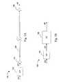
- FIG. 1Ais a block diagram of a multimode optical transmission system
- FIG. 1Bis a block diagram of a mathematical representation of the transmission system of FIG. 1A ;
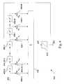
- FIG. 2is a block diagram of an adaptive channel-compensating equalizer, in accordance with an embodiment of the present invention
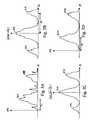
- FIG. 3Ashows an exemplary received signal
- FIG. 3Billustrates a first correlation function of the received signal in FIG. 3A , in accordance with an embodiment of the present invention
- FIG. 3Cillustrates a second correlation function of the received signal in FIG. 3A , in accordance with an embodiment of the present invention
- FIG. 3Dshows an estimated channel response of the received signal in FIG. 3A determined by methods of the present invention.
- FIG. 4is a block diagram of an infinite impulse response filter, in accordance with an embodiment of the present invention.
- subsetis used generally to mean a portion of something, up to and including the entirety of the something.
- a typical multimode optical transmission system 100includes a digital-to-analog (D/A) converter 102 , a transmission amplifier 104 , a multimode fiber 106 , and a receiver 108 .
- An input bit sequence x[n]is provided to the D/A converter 102 , which converts the sequence to an input signal x(t).
- the transmission amplifier 104transmits the input signal on the multimode fiber.
- the receiver 108determines an output signal s(t).
- the input bit stream x[n]can be unambiguously recovered from this output signal s(t). In practice, however, this is difficult due to the distorting effects of amplification by amplifier 104 , propagation through fiber 106 , and reception by receiver 108 of x(t).
- FIG. 1Bdepicts such a mathematical model of the multimode optical transmission system 100 of FIG. 1 A.
- Channel 106replaces the amplifier, fiber, and receiver of the transmission system. It is assumed that channel 106 introduces linear distortion only, so that the channel can be completely characterized by the channel impulse response h(t). As discussed, the channel impulse response may vary over time due to, among other possible causes, kinks in the fiber, temporal variations of the fiber, and fluctuations in power supply levels of the transmitter and/or receiver.
- output signal s(t)is determined as a convolution of the input signal x(t) and the channel impulse response h(t).
- the output signalcan be employed to produce an accurate estimate of the input signal x(t) and, in turn, the input bit stream x[n]. In practice, however, it is difficult to determine the channel response, especially because it is typically time-varying.
- LMS and RLS techniquescan be used to model the channel response. All of these techniques, however, require that a known training sequence be injected into input bit stream x[n]. This causes that the transmission system to be unavailable for data transmission for some period of time, diminishing the capacity of the system. Furthermore, there is the above-mentioned issue of interoperability, where any given transmitter may not know it needs to transmit the training sequence to begin with, and thus the system may never initialize to begin successful transmission.
- FIG. 2a block diagram for one embodiment of the channel-compensating equalizer of the present invention is presented in FIG. 2 .
- the incoming signal s(t)is provided as an input to correlation logic blocks 202 - 1 , 2 . . . N to perform signal analysis, as will be explained in further detail below.
- the correlation logic blocksare preferably implemented in analog logic, but in other embodiments, may also be implemented in digital logic, or in a combination of analog and digital logic. Using analog computational logic allows the signal analysis to occur at a faster speed than with digital processing, and requires less power as well.
- the correlation logicutilizes a delay line (to compute the term that includes the delay ⁇ t), multipliers to multiply terms together to achieve powers, and capacitors to integrate the time-average of the functions.
- ⁇ tthe delay line
- multipliersto multiply terms together to achieve powers
- capacitorsto integrate the time-average of the functions.
- other types of computational logicmay also be used to compute the same function, as appreciated by one of skill in the art.
- a variety of different types of correlation functionsare employed by the present invention.
- the output of the correlation logic blocksis provided to A/D logic 204 , which may be a single A/D converter, or multiple A/D converters in parallel.
- the digital samples of the correlation functionsare then provided as an input to microcontroller 206 , which deduces enough information from these functions to predict the channel response h(t).
- the microcontrolleruses the channel response h(t) to generate an initial set of filter coefficients, or tap weights, for the equalizer 210 to compensate for the effects of the channel response.
- the microcontrollertracks the time-varying aspects of the channel response, and adaptively updates the filter coefficients of the equalizer.
- the clock rate of the microcontrollercan be slower than the sample rate for the data signal s(t), as long as it is fast enough to provide appropriate adaptive updates to the equalizer 210 .
- the microcontroller outputmust be converted to an analog signal by D/A logic 208 , which may be a single D/A converter, or multiple D/A converters in parallel. (The determination and application of the tap weights to the equalizer 210 , as well as the configuration of the equalizer 210 , will be discussed in further detail below in conjunction with FIG. 4 ).
- the data clockis recovered by clock and data recovery (CDR) circuit 212 .
- Local oscillator 214provides the clock signal. While a CDR circuit typically extracts the data clock from the received signal s(t), in one embodiment of the present invention, the CDR circuit 212 extracts the clock from the equalized output signal 220 . This is possible because the equalizer 210 does not obtain convergence or data lock through an error-feedback adaptive algorithm, but rather from the compensation of the channel response by the microcontroller. By determining the data clock from the equalized signal, clock recovery is easier and more likely to compatible with an “off-the-shelf” CDR circuit, and also reduces the likelihood of false lock.
- the equalizer 210receives the input signal s(t) as its input, equalizes the signal, and outputs the equalized output signal 220 , which is substantially similar to the originally-transmitted signal r(t).
- operation of the channel-compensating equalizer of the present inventioncan be divided into two main steps: (1) determining the channel response of the channel over which the received signal is obtained; and (2) using the channel response to determine a set of filter coefficients for the equalizer to filter out the effects of the channel response to recover the originally-transmitted signal.
- Different techniques for implementing each step, in conjunction with different embodiments of the present invention,will be described next.
- the next two sectionsdescribe exemplary techniques for determining the channel response for step (1) (i.e., a “peak detection method” and an “explicit model-fitting method”), followed by an explanation of how to use the channel response to determine the set of filter coefficients, and how to adaptively update the coefficients, for step (2).
- one embodiment of the inventioncomputes correlation statistics of the output signal s(t) that are used to determine an estimate ⁇ tilde over (h) ⁇ (t) of the true channel response, without direct knowledge of any portion of the input bit stream.
- This embodimentbuilds a model of the channel response based on Gaussian peaks (or other peak shapes), and then uses the correlation statistics to determine the relative spacing and height of those peaks.
- a series of correlation statisticsare computed based on s(t).
- Correlation functionsare a measure of the similarity between two signals as a function of time shift between them. Correlation is at a maximum when two signals are similar in shape and in phase (or “unshifted” with respect to each other).
- the correlation statisticsare autocorrelation functions. Autocorrelation functions are correlations of a signal onto itself. By using autocorrelation functions, any uncorrelated data will drop out of the autocorrelation, or will be represented primarily as a spike that can be filtered out or ignored. In other words, the autocorrelation reduces the data components of the received signal. The remaining information in the autocorrelation will represent the largely periodic channel response.
- the transmitted datais uncorrelated, in part because a typical optoelectronic transmission system for multimode fiber utilizes a scrambler on the transmitter portion to assure that the transmitted data is substantially random.
- the ratio of framing bits to payload bitsis generally small enough that the framing bits can be compensated for by the microcontroller 206 , or, in some applications, may have sufficiently minimal effect as to be ignored.
- an example of an output (received) signal s(t)is shown.
- This output signalrepresents the received signal after transmission of a single data pulse (representing a logic-high value) transmitted across the channel.
- the corresponding recovered channel response h(t)(which will be determined in the manner described below) is shown. Comparing the two, it is clear that the received signal s(t) contains additional noise other than the channel response itself. If there were no dispersive effects other than those represented by the channel response, the output signal corresponding to a pulse could be measured directly to determine h(t). But, as shown, there may be other random noise in the channel, or the channel responses corresponding to other nearby pulses may crowd into the current channel response.
- the autocorrelation functionsare used to distinguish the channel response contributions (which generally repeat and thus show up as correlations) from the random data (which generally fall out of the autocorrelation).
- these correlation statistics S 0 , S 1 , and S 2do not depend explicitly on the input data sequence x[n]. Furthermore, taken together, they allow an accurate estimate response of the channel impulse response h(t) to be computed. Note that the notation “ ⁇ >” means a time-average of the terms inside the brackets.
- the three correlation functions S 0 , S 1 , and S 2 illustratedare merely an example of the type of functions that can be used in accordance with the precepts of the present invention.
- other non-linear termscan be used in place of the square-root function, such as a power function:
- s(t)may be sampled by an analog-to-digital (A/D) converter, the samples stored in a semiconductor memory, and the computations necessary to compute the above quantities carried out on a microprocessor.
- A/Danalog-to-digital
- the correlation statisticscan be computed using analog circuitry—for example, using analog-multiply circuits, analog circuits that measure a time average by built-up voltage on a capacitor, and analog circuits that determine square-root and power-law functions.
- the channel impulse responseis characterized by a discrete number of peaks, as depicted by peaks 320 and 322 in FIG. 3 D.
- T da delay between the arrival of each mode at the receiving end of the fiber.
- the x-axes of FIGS. 3A-3Dare time t.
- This delay, as well as the relative heights of the two-peak ( 320 and 322 ) channel responsecan be derived from the correlation statistics, as will be shown.
- peaks 302 and peaks 304 of the received signal s(t)correspond to peaks 320 and 322 ; however, the received signal s(t) contains the additional aforementioned noise and convolved data.
- correlation statistic S 0exhibits three peaks.
- S 0is s(t) multiplied by itself.
- the height of peak 306will be generally proportional to the square of the height of peak 302 (corresponding to channel-response peak 320 ) plus the square of the height of peak 304 (corresponding to channel-response peak 322 ).
- Peak 308 in S 0results from the computation of correlation S 0 when the delay, ⁇ t, is equal to the intermode delay T d .
- the height of peak 308will be proportional to the height of peak 302 (corresponding to channel-response peak 320 ) multiplied by the height of peak 304 (corresponding to channel-response peak 322 ). This is because, after shifting s(t) over by T d , peak 302 is multiplied by zero (or some small value approaching zero), peak 302 is multiplied by peak 304 , and peak 304 is multiplied by zero (or some small value), resulting in a predominance of the product of peaks 302 and 304 .
- the noise surrounding peaks 302 and 304is assumed to be random (uncorrelated), and should effectively drop out because it will be multiplied by zero or a small number.
- Peak 310is equal in height to that of peak 308 , as it results from the computation of correlation S 0 when the delay, ⁇ t, is equal to negative of the intermode delay T d . Thus, no new information is gained from examining the position or height of peak 310 .
- correlation statistic S 1contains three main peaks 312 , 314 , and 316 .
- the following three relationshipscan be determined about the peaks of the channel response and the peaks of the correlation statistic S 1 :
- the peakscan be modeled as a series of Gaussian peaks, for example, with a width corresponding to the pulse width of the received signal, and a height determined by the method described above.
- the actual number of peaks used for the modelcan be a predetermined value, or can vary depending on the channel information.
- the above-described techniqueis one example of a method for determining the height and relative positioning of the peaks of the channel response h(t)
- other methods for determining the channel responsecan be employed in the present invention.
- the channel responsecould be determined partially through measurement (for a pulse) and partially through correlation statistics.
- the channel responsecan be determined through an explicit model-fitting procedure—a technique that will be described next.
- the present inventiondetermines the channel response by computing models of correlation statistics of the output signal s(t), which are then iteratively optimized to determine coefficients that can be used to determine an estimate ⁇ tilde over (h) ⁇ (t) of the true channel response. Again, this occurs without direct knowledge of any portion of the input bit stream.
- the output signal s(t)is first measured for some period of time T m and stored.
- correlation functions s 0 , S 1 , and S 2discussed above in the context of the peak detection method.
- the correlation functionsare data-independent, that is, that they reduce or eliminate the data components of the received signal
- input data sequence x[n]assumes one of only two values—logic high (V H ) or logic low (V L ), with a bit period of duration.
- the shape of the pulse function p(t)is produced by D/A 102 (see FIG. 1 ) and is known in practice.
- references to the channel response h(t)may also be references to q(t), interchangeably, with an additional [and generally unnecessary] deconvolution required to derive the actual channel response.
- references to the channel response h(t)may also be references to q(t), interchangeably, with an additional [and generally unnecessary] deconvolution required to derive the actual channel response.
- the discussionfocuses on the channel response h(t) instead of the convolved channel response and pulse function q(t)).
- the m-basis functions b m (t)are known functions of time and the M expansion coefficients ⁇ m are to be determined. Approximation of unknown functions by a finite number of basis functions is well-known in the art of numerical computation.
- the basis function b m (t)could be cubic splines, Legendre polynomials, or wavelets.
- the basis functions b m (t) in this embodimentwould be predetermined by the computational logic, and could be dynamically optimized.
- the expansion coefficients ⁇ mare determined by modeling the correlation statistics ⁇ tilde over (S) ⁇ 0 , ⁇ tilde over (S) ⁇ 1 , ⁇ tilde over (S) ⁇ 2 based on the expansion coefficients, using a curve-fitting optimization (e.g., a steepest-descent function) to determine the best coefficients, and, once determined, using the same coefficients to determine the model of the channel response.
- Other correlation statisticscan be similarly estimated.
- an initial set of expansion coefficients ⁇ mmust be determined, to provide the initial model for each correlation statistic.
- these initial values for the coefficientsare predetermined by the computational logic (like the basis functions), and could, as one example, simply be set to zero.
- the initial values for the expansion coefficientscould be determined by the peak detection method described above.
- the actual correlation statisticsmust also be determined, by measuring the received signal s(t) (e.g., by sampling the signal with an A/D converter), and by computing the correlation statistics ⁇ tilde over (S) ⁇ 0 , ⁇ tilde over (S) ⁇ 1 , ⁇ tilde over (S) ⁇ based on the equations described above.
- the purpose of the scalar error functionis to denote the error between the actual correlation statistics and the modeled correlation statistics, summed over the total number of statistics (e.g., two in this case).
- the modeled correlation statisticsare optimally “fit” to the actual correlation statistics, and hence the optimal set of expansion coefficients is determined.
- ⁇ i+1⁇ i + ⁇ E ( ⁇ i )
- ithe number of the current iteration
- ⁇a coefficient
- ⁇denotes the gradient with respect to the expansion coefficients.
- the iterationscan be stopped when the change in estimates of the expansion coefficients becomes small in some norm.
- This type of iterative calculationcan be quickly conducted by a microprocessor, or by specialized digital circuitry in an alternative embodiment.
- the computational logicwill use those coefficients, together with the basis functions b m (t), to determine the model of the channel response ⁇ tilde over (h) ⁇ (t).
- the modeled channel response ⁇ tilde over (h) ⁇ (t)should be approximately equal to the actual channel response h(t).
- the second general step of the present inventionis to apply the calculated channel response (whether determined by the peak detection method, by the model-fitting method, or by an alternative correlation technique) to obtain filter coefficients for the equalizer.
- the equalizeruses the channel response h(t) to cancel out or reduce the effects of the channel response, and to equalize the received signal s(t).
- adaptive equalizationis performed by an infinite impulse response (IRR) equalizer with a minimum mean squared error (MMSE) filter.
- IRRinfinite impulse response
- MMSEminimum mean squared error
- IIR equalizeris designed to minimize the expected squared error between the estimate of the current data symbol â[n] and the true data symbol a[n].
- the filtermay be implemented purely in digital hardware, purely in analog hardware, or in a combination of analog and digital hardware. Referring to FIG. 4 , IIR filter 400 includes:
- N in the precursor filter and the number of coefficients M in the postcursor filterimpact both the cost and performance of the DFE in estimating the true data symbol.
- larger number of coefficientswill lead to more accurate estimation of the true data symbol, but will be more expensive to implement in hardware.
- smaller numbers of coefficientswill generally lead to less reliable estimation of the true data symbol, while requiring a lower cost to implement in hardware.
- the actual number of coefficients in the precursor and postcursor sections of filter 400are determined by a designer before construction of the filter, and do not change for a given implementation.
- the coefficients c 0 ,c 1 , . . . ,c N ⁇ 1 and d 1 ,d 2 , . . . ,d Mare computed both before and during the operation of the filter. Computation of the coefficients is accomplished by the microcontroller 206 (see FIG. 2 ) with a routine that receives the current estimate of the channel response as an input, and returns the optimal (from a MMSE standpoint) coefficients as an output.
- ⁇[ ⁇ - ( N - 1 ) , - ( N - 1 ) ⁇ - ( N - 1 ) , - ( N - 2 ) ⁇ ⁇ - ( N - 1 ) , 0 ⁇ - ( N - 2 ) , - ( N - 1 ) ⁇ ⁇ ⁇ ⁇ 0 , - ( N - 1 ) ⁇ 0 , - ( N - 2 ) ⁇ ⁇ 0 , 0 ]
- ⁇ kM + 1 ⁇ ⁇ ⁇ h ⁇
- the correlation statistics of the input data symbol sequenceare determined (e.g., S 0 ,S 1 , and S 2 ), and the channel response is estimated.
- a pseudocode implementation of the Levinson algorithmis shown in Table 1:
- the optimal tap weights of the IIR filter depicted in FIG. 4can be determined.
- One feature of the present inventionis the ability to update the estimates of the tap weights based on changes in the estimate of the channel response. This is accomplished using a scheme for adaptive equalization, such as the following scheme, which performs adaptive equalization at a rate equal to the data symbol rate of the channel:
- the above stepsmay be repeated at a rate of one-tenth, one-thousandth, or some other fractional speed, of the data symbol rate to allow sufficient time for the computation of new coefficients.
- the microcontroller 206can be slower than the sample rate, and hence utilize slower, less expensive, and less power-consumptive D/A and A/D converters.
- the equalized and estimated data symbol â[n]is used as an estimate of the most recent data symbol transmitted into the channel.
- the output y[n]is used to drive a timing recovery circuit (see FIG. 2 ) in one embodiment.
- Timing recovery circuitsare well known in the art of digital signal processing (DSP). See Chapter 17, pp. 737-764, Digital Communication, Second Edition, Edward A. Lee and David G. Messerschmitt, Kluwer Academic Publishers, Boston, USA, 1994, which is hereby incorporated by reference.
- the equalizermay be a decision-feedback equalizer (DFE) that determines updated filter coefficients using an error signal determined from the differences in the pre- and post-slicer signals.
- DFEdecision-feedback equalizer
- the DFEmay optionally contain a finite impulse response (FIR) filter on its front end.
- FIRfinite impulse response
Landscapes
- Physics & Mathematics (AREA)
- Nonlinear Science (AREA)
- Electromagnetism (AREA)
- Engineering & Computer Science (AREA)
- Computer Networks & Wireless Communication (AREA)
- Signal Processing (AREA)
- Cable Transmission Systems, Equalization Of Radio And Reduction Of Echo (AREA)
- Optical Communication System (AREA)
Abstract
Description
S0=<s(t)s(t+δt)>−<s(t)>2
S1=<s(t)√{square root over (s(t+δ)}t)>−<s(t)><√{square root over (s(t))}>
S2=<√{square root over (s(t))}s(t+δt)>−<s(t)><√{square root over (s(t))}>
S2=<s(t)4s(t+δt)>−<s(t)><s(t)4>
h320+h322=h306
h320*h322=h308
However, these two equations are not sufficient by themselves to unambiguously determine the unknown quantities h320and h322.
h320√{square root over (h322)}=h314
h322√{square root over (h320)}=h316
- 1. Determine the location of the three peaks in S0;
- 2. Measure the heights of the
largest peak 306 and thesmaller peak 308; - 3. Measure the heights of the three
peaks - 4. Determine the intermode delay Tdand the height of the two peaks in the impulse response h320and h322.
The shape of the pulse function p(t) is produced by D/A102 (see
where q(t) is implicitly defined as the convolution of the pulse p(t) and the channel impulse response. (Note: throughout this document, references to the channel response h(t) may also be references to q(t), interchangeably, with an additional [and generally unnecessary] deconvolution required to derive the actual channel response. For ease of explanation, however, the discussion focuses on the channel response h(t) instead of the convolved channel response and pulse function q(t)).
Then, using the aforementioned expression for s(t), the first part of S0can be expressed as:
where σ is the standard deviation of the input data stream (a known quantity), and it has been assumed that the input data stream is uncorrelated, as discussed previously. The second part of S0, while not set forth here, is similar.
In this expression, the m-basis functions bm(t) are known functions of time and the M expansion coefficients λmare to be determined. Approximation of unknown functions by a finite number of basis functions is well-known in the art of numerical computation. For example, the basis function bm(t) could be cubic splines, Legendre polynomials, or wavelets. The basis functions bm(t) in this embodiment would be predetermined by the computational logic, and could be dynamically optimized.
{tilde over (S)}0=ƒ0(λ1, λ2, . . . λM)=ƒ(λ)
where the notation λ is a shorthand for the M-vector of the expansion coefficients. Other correlation statistics can be similarly estimated.
The purpose of the scalar error function is to denote the error between the actual correlation statistics and the modeled correlation statistics, summed over the total number of statistics (e.g., two in this case). Thus, by minimizing the value of the scalar error function, the modeled correlation statistics are optimally “fit” to the actual correlation statistics, and hence the optimal set of expansion coefficients is determined.
λi+1=λi+β∇E(λi)
where i is the number of the current iteration, β is a coefficient, and ∇ denotes the gradient with respect to the expansion coefficients. The iterations can be stopped when the change in estimates of the expansion coefficients becomes small in some norm. This type of iterative calculation can be quickly conducted by a microprocessor, or by specialized digital circuitry in an alternative embodiment.
- a number of one-bit delays402-1 . . . N in an N-order precursor section for canceling intersymbol interference (ISI) from future data symbols;
- a number of coefficient multipliers404-1 . . . N in the precursor section; precursor coefficients C0, C1, . . . , cN−1;
- a number of one-bit delays406-1 . . . M in an M-order postcursor section for canceling intersymbol interference (ISI) from past data symbols;
- a number of coefficient multipliers408-1 . . . M in the postcursor section;
- postcursor coefficients d1, d2, . . . , dM;
summer 410 for combining the results of the pre- and postcursor filters; and- slicer412 for estimating the current data symbol based on the combined output of the precursor and postcursor filters.
h[n]=h(nTs),
where n is an integer representing a sample number, Tsis the sampling period (the arithmetical inverse of the data transmission rate), and h(t) is the channel response. Allowing n=0 to refer to the first nonzero sample of the channel response, a vector of channel response samples is defined as:
where σais the standard deviation of the input data symbol sequence a[n]. It is also convenient to define the autocorrelation matrix of the received symbols,
where the individual matrix elements are given by:
Finally, the unknown coefficients of the precursor filter are denoted:
In observance of the notations defined above, the coefficients of the precursor filter that yield an MMSE behavior are:
c=(Φ+λI)−1h (Eq. A)
(where I is the identity matrix and λ is a small positive number to prevent zero eigenvalues in order to reduce divergence of the inverse matrix), with corresponding postcursor coefficients:
- 1. Compute and store the N-vector
- 2. Compute and store the N-by-N matrix
- where each element is computed in accordance with the formula
- 3. Solve the matrix equation ĉ=({circumflex over (Φ)}+λÎ)−1ĥ, yielding an approximation ĉ of the optimal precursor tap weights; and
- 4. Compute an approximation of the optimal postcursor tap weights via the formula
| TABLE 1 |
| if k < N − 1 then |
| end |
| end |
- 1. Retrieve the last unequalized data symbol s[n];
- 2. Update the estimate of the channel response ĥ[0],ĥ[1], . . . h[N−1];
- 3. Calculate an estimate of the optimal precursor filter tap weights ĉ;
- 4. Calculate an estimate of the optimal postcursor filter coefficients {circumflex over (d)}; and
- 5. Apply the new estimates of the optimal precursor and postcursor coefficients to the IIR filter.
- E[x]—the statistical expectation, or mean, of random variable (r.v.)x. For a discrete r.v., the expectation can be explicitly evaluated via
- where the summation is performed over all possible values of the r.v. and P(x=j) denotes the probability that the r.v. assumes the value j.
- σx—the standard deviation of r.v. x. For any r.v., the standard deviation can be explicitly evaluated via σx=√{square root over (E[x2]−E[x]2)}.
- <f (t)>—the time-average of a function ƒ(t). The time-average is explicitly given by
- Note: Under some circumstances, the time-average is a good approximation of the expectation. For example, the function ƒ(t) can sometimes be expressed as the sum of a series of deterministic time functions whose amplitude is modulated by a discrete r.v.,
- where xnis an instance of the r.v. x, Tsis a deterministic constant and p(t) is a deterministic function of time having zero time-average. In this case, the mean of the r.v. is well-approximated by E[x]≈<ƒ(t)>.
- A k-vector v is a k-tuple of values v1, v2, . . . , vkand is denoted
- An m-by-n matrix A is a n-tuple of m-vectors a1,a2, . . . anand is denoted
- The inner product of two k-vectors v and w is computed as
- and is denoted
- The product of an n-by-k matrix A and a k-vector v is a n-vector w. The elements of w are computed in accordance with
- This operation is denoted
- or, alternately, Av.
- The inverse of an m-by-m matrix A, when it exists and is unique, is another, possibly different m-by-m matrix denoted by A−1. For arbitrary m-vectors v and w, if the matrix A satisfies w=Av its inverse must satisfy v=A−1w.
- E[x]—the statistical expectation, or mean, of random variable (r.v.)x. For a discrete r.v., the expectation can be explicitly evaluated via
Claims (19)
Priority Applications (3)
| Application Number | Priority Date | Filing Date | Title |
|---|---|---|---|
| US10/419,023US6956917B2 (en) | 2003-04-17 | 2003-04-17 | Method and apparatus for reducing interference in an optical data stream using data-independent equalization |
| US10/789,622US6909742B1 (en) | 2003-04-17 | 2004-02-27 | Method and apparatus for reducing interference in a data stream using autocorrelation derived equalization |
| PCT/US2004/012074WO2004095082A2 (en) | 2003-04-17 | 2004-04-19 | Method and apparatus for reducing interference in an optical data stream using dataindependent equalization |
Applications Claiming Priority (1)
| Application Number | Priority Date | Filing Date | Title |
|---|---|---|---|
| US10/419,023US6956917B2 (en) | 2003-04-17 | 2003-04-17 | Method and apparatus for reducing interference in an optical data stream using data-independent equalization |
Related Child Applications (1)
| Application Number | Title | Priority Date | Filing Date |
|---|---|---|---|
| US10/789,622Continuation-In-PartUS6909742B1 (en) | 2003-04-17 | 2004-02-27 | Method and apparatus for reducing interference in a data stream using autocorrelation derived equalization |
Publications (2)
| Publication Number | Publication Date |
|---|---|
| US20040208266A1 US20040208266A1 (en) | 2004-10-21 |
| US6956917B2true US6956917B2 (en) | 2005-10-18 |
Family
ID=33159249
Family Applications (2)
| Application Number | Title | Priority Date | Filing Date |
|---|---|---|---|
| US10/419,023Expired - LifetimeUS6956917B2 (en) | 2003-04-17 | 2003-04-17 | Method and apparatus for reducing interference in an optical data stream using data-independent equalization |
| US10/789,622Expired - LifetimeUS6909742B1 (en) | 2003-04-17 | 2004-02-27 | Method and apparatus for reducing interference in a data stream using autocorrelation derived equalization |
Family Applications After (1)
| Application Number | Title | Priority Date | Filing Date |
|---|---|---|---|
| US10/789,622Expired - LifetimeUS6909742B1 (en) | 2003-04-17 | 2004-02-27 | Method and apparatus for reducing interference in a data stream using autocorrelation derived equalization |
Country Status (2)
| Country | Link |
|---|---|
| US (2) | US6956917B2 (en) |
| WO (1) | WO2004095082A2 (en) |
Cited By (26)
| Publication number | Priority date | Publication date | Assignee | Title |
|---|---|---|---|---|
| US20040179849A1 (en)* | 2003-03-14 | 2004-09-16 | Tetsuya Miyazaki | Optical receiver and method for controlling dispersion compensation |
| US20050195893A1 (en)* | 2004-03-02 | 2005-09-08 | Xilinx, Inc. | Bit-edge zero forcing equalizer |
| US20070065162A1 (en)* | 2003-05-27 | 2007-03-22 | Nobuhiko Kikuchi | Signal waveform deterioration compensator |
| US20070080834A1 (en)* | 2005-10-07 | 2007-04-12 | Auld David R | Adaptive sample rate converter |
| US20070280341A1 (en)* | 2006-05-30 | 2007-12-06 | Fujitsu Limited | System and Method for the Adjustment of Offset Compensation Applied to a Signal |
| US20070280342A1 (en)* | 2006-05-30 | 2007-12-06 | Fujitsu Limited | System and Method for the Adjustment of Compensation Applied to a Signal |
| US20070280390A1 (en)* | 2006-05-30 | 2007-12-06 | Fujitsu Limited | System and Method for the Non-Linear Adjustment of Compensation Applied to a Signal |
| US20070280389A1 (en)* | 2006-05-30 | 2007-12-06 | Fujitsu Limited | System and Method for Asymmetrically Adjusting Compensation Applied to a Signal |
| US20070280384A1 (en)* | 2006-05-30 | 2007-12-06 | Fujitsu Limited | System and Method for Independently Adjusting Multiple Offset Compensations Applied to a Signal |
| US20070297209A1 (en)* | 2006-05-30 | 2007-12-27 | Fujitsu Limited | System and Method for Adjusting Offset Compensation Applied to a Signal |
| US20070297248A1 (en)* | 2006-05-30 | 2007-12-27 | Fujitsu Limited | System and Method for Adjusting Compensation Applied to a Signal Using Filter Patterns |
| US20080056344A1 (en)* | 2006-05-30 | 2008-03-06 | Fujitsu Limited | System and Method for Independently Adjusting Multiple Compensations Applied to a Signal |
| US7760798B2 (en) | 2006-05-30 | 2010-07-20 | Fujitsu Limited | System and method for adjusting compensation applied to a signal |
| US7804921B2 (en) | 2006-05-30 | 2010-09-28 | Fujitsu Limited | System and method for decoupling multiple control loops |
| US7804894B2 (en) | 2006-05-30 | 2010-09-28 | Fujitsu Limited | System and method for the adjustment of compensation applied to a signal using filter patterns |
| US8798484B2 (en) | 2012-02-16 | 2014-08-05 | International Business Machines Corporation | Optical receiver using infinite impulse response decision feedback equalization |
| US20160226697A1 (en)* | 2013-09-24 | 2016-08-04 | Proteus Digital Health, Inc. | Method and apparatus for use with received electromagnetic signal at a frequency not known exactly in advance |
| US9439566B2 (en) | 2008-12-15 | 2016-09-13 | Proteus Digital Health, Inc. | Re-wearable wireless device |
| US9439599B2 (en) | 2011-03-11 | 2016-09-13 | Proteus Digital Health, Inc. | Wearable personal body associated device with various physical configurations |
| US9659423B2 (en) | 2008-12-15 | 2017-05-23 | Proteus Digital Health, Inc. | Personal authentication apparatus system and method |
| US9756874B2 (en) | 2011-07-11 | 2017-09-12 | Proteus Digital Health, Inc. | Masticable ingestible product and communication system therefor |
| US9787511B2 (en) | 2013-09-20 | 2017-10-10 | Proteus Digital Health, Inc. | Methods, devices and systems for receiving and decoding a signal in the presence of noise using slices and warping |
| US10084880B2 (en) | 2013-11-04 | 2018-09-25 | Proteus Digital Health, Inc. | Social media networking based on physiologic information |
| US10376218B2 (en) | 2010-02-01 | 2019-08-13 | Proteus Digital Health, Inc. | Data gathering system |
| US10398161B2 (en) | 2014-01-21 | 2019-09-03 | Proteus Digital Heal Th, Inc. | Masticable ingestible product and communication system therefor |
| US11158149B2 (en) | 2013-03-15 | 2021-10-26 | Otsuka Pharmaceutical Co., Ltd. | Personal authentication apparatus system and method |
Families Citing this family (38)
| Publication number | Priority date | Publication date | Assignee | Title |
|---|---|---|---|---|
| US7715508B2 (en)* | 2005-11-15 | 2010-05-11 | Tensorcomm, Incorporated | Iterative interference cancellation using mixed feedback weights and stabilizing step sizes |
| US8005128B1 (en) | 2003-09-23 | 2011-08-23 | Rambus Inc. | Methods for estimation and interference cancellation for signal processing |
| US7356074B2 (en)* | 2003-05-08 | 2008-04-08 | Rf Micro Devices, Inc. | Estimation of multipath channel with sub-chip resolution |
| US7408981B2 (en)* | 2003-05-20 | 2008-08-05 | Rambus Inc. | Methods and circuits for performing margining tests in the presence of a decision feedback equalizer |
| US7590175B2 (en)* | 2003-05-20 | 2009-09-15 | Rambus Inc. | DFE margin test methods and circuits that decouple sample and feedback timing |
| US7627029B2 (en) | 2003-05-20 | 2009-12-01 | Rambus Inc. | Margin test methods and circuits |
| US7084476B2 (en)* | 2004-02-26 | 2006-08-01 | International Business Machines Corp. | Integrated circuit logic with self compensating block delays |
| US7639736B2 (en)* | 2004-05-21 | 2009-12-29 | Rambus Inc. | Adaptive receive-side equalization |
| US7738546B2 (en)* | 2004-09-27 | 2010-06-15 | Intel Corporation | Feed forward equalizer for a communication system |
| US7551667B2 (en)* | 2004-09-27 | 2009-06-23 | Intel Corporation | Feed forward equalizer |
| GB2422989A (en)* | 2005-02-03 | 2006-08-09 | Agilent Technologies Inc | Correlating a received data signal with a time delayed version of the signal to obtain a measurement of inter-symbol interference |
| US7991088B2 (en) | 2005-11-15 | 2011-08-02 | Tommy Guess | Iterative interference cancellation using mixed feedback weights and stabilizing step sizes |
| US7826516B2 (en) | 2005-11-15 | 2010-11-02 | Rambus Inc. | Iterative interference canceller for wireless multiple-access systems with multiple receive antennas |
| US7711075B2 (en) | 2005-11-15 | 2010-05-04 | Tensorcomm Incorporated | Iterative interference cancellation using mixed feedback weights and stabilizing step sizes |
| US7724848B2 (en)* | 2005-07-26 | 2010-05-25 | Data Device Corporation | Predictive signal cancellation for extracting 1 Mb/s MIL-STD-1553 component from composite high performance 1553 signal |
| US7702048B2 (en)* | 2005-11-15 | 2010-04-20 | Tensorcomm, Incorporated | Iterative interference cancellation using mixed feedback weights and stabilizing step sizes |
| US7623602B2 (en)* | 2005-11-15 | 2009-11-24 | Tensorcomm, Inc. | Iterative interference canceller for wireless multiple-access systems employing closed loop transmit diversity |
| US20070110135A1 (en)* | 2005-11-15 | 2007-05-17 | Tommy Guess | Iterative interference cancellation for MIMO-OFDM receivers |
| US20080240224A1 (en)* | 2006-04-18 | 2008-10-02 | Carballo Juan A | Structure for one-sample-per-bit decision feedback equalizer (dfe) clock and data recovery |
| US7809054B2 (en)* | 2006-04-18 | 2010-10-05 | International Business Machines Corporation | One-sample-per-bit decision feedback equalizer (DFE) clock and data recovery |
| US7920588B2 (en)* | 2006-05-22 | 2011-04-05 | Edgewater Computer Systems, Inc. | Data communications system and method of data transmission |
| US10162782B2 (en) | 2006-05-22 | 2018-12-25 | Edgewater Computer Systems, Inc. | Data communications system and method of data transmission |
| US7822126B2 (en)* | 2006-08-10 | 2010-10-26 | Edgewater Computer Systems, Inc. | Interference cancellation system and method |
| US7907690B2 (en)* | 2006-10-17 | 2011-03-15 | Edgewater Computer Systems, Inc. | Interference cancellation system and method using impulse response |
| US8054873B2 (en)* | 2007-03-15 | 2011-11-08 | Netlogic Microsystems, Inc. | Joint phased training of equalizer and echo canceller |
| US8040943B1 (en) | 2007-03-15 | 2011-10-18 | Netlogic Microsystems, Inc. | Least mean square (LMS) engine for multilevel signal |
| US8064510B1 (en) | 2007-03-15 | 2011-11-22 | Netlogic Microsystems, Inc. | Analog encoder based slicer |
| US8095005B2 (en)* | 2007-10-26 | 2012-01-10 | Cisco Technology, Inc. | Multimode fiber link probe |
| US20100122003A1 (en)* | 2008-11-10 | 2010-05-13 | Nec Laboratories America, Inc. | Ring-based high speed bus interface |
| US8619897B2 (en)* | 2008-12-09 | 2013-12-31 | Netlogic Microsystems, Inc. | Method and apparatus of frequency domain echo canceller |
| GB201001488D0 (en)* | 2010-01-29 | 2010-03-17 | Icera Inc | An equalizer for wireless receivers |
| US8817918B2 (en)* | 2011-12-13 | 2014-08-26 | Vixs Systems, Inc. | Cyclic prefix and precursor joint estimation |
| US20150349988A1 (en)* | 2014-05-30 | 2015-12-03 | Lsi Corporation | Selecting floating tap positions in a floating tap equalizer |
| US9590799B2 (en)* | 2015-03-21 | 2017-03-07 | Finisar Corporation | Clock recovery and equalizer estimation in a multi-channel receiver |
| US10129053B2 (en)* | 2015-05-28 | 2018-11-13 | Multiphy Ltd. | Steepest descent FFE computation and tracking |
| JP6020696B1 (en)* | 2015-11-05 | 2016-11-02 | Nttエレクトロニクス株式会社 | Chromatic dispersion estimation circuit, optical receiver, and chromatic dispersion amount estimation method |
| EP3799437A1 (en)* | 2019-09-24 | 2021-03-31 | Microsoft Technology Licensing, LLC | Communication in a switching network |
| CN114168796B (en)* | 2022-02-10 | 2022-04-15 | 中国空气动力研究与发展中心计算空气动力研究所 | Method for establishing high-altitude aerodynamic database of aircraft |
Citations (1)
| Publication number | Priority date | Publication date | Assignee | Title |
|---|---|---|---|---|
| US5572552A (en)* | 1994-01-27 | 1996-11-05 | Ericsson Ge Mobile Communications Inc. | Method and system for demodulation of downlink CDMA signals |
Family Cites Families (4)
| Publication number | Priority date | Publication date | Assignee | Title |
|---|---|---|---|---|
| US3764914A (en)* | 1971-12-27 | 1973-10-09 | Ibm | High speed line equalizer |
| JPH1198066A (en)* | 1997-09-19 | 1999-04-09 | Hitachi Denshi Ltd | Demodulator and demodulation method |
| US6754340B1 (en)* | 1998-12-22 | 2004-06-22 | Nortel Networks Limited | Stable adaptive filter and method |
| US6647078B1 (en)* | 2000-06-30 | 2003-11-11 | Motorola, Inc. | Method and device for multi-user frequency-domain channel estimation based on gradient optimization techniques |
- 2003
- 2003-04-17USUS10/419,023patent/US6956917B2/ennot_activeExpired - Lifetime
- 2004
- 2004-02-27USUS10/789,622patent/US6909742B1/ennot_activeExpired - Lifetime
- 2004-04-19WOPCT/US2004/012074patent/WO2004095082A2/enactiveApplication Filing
Patent Citations (1)
| Publication number | Priority date | Publication date | Assignee | Title |
|---|---|---|---|---|
| US5572552A (en)* | 1994-01-27 | 1996-11-05 | Ericsson Ge Mobile Communications Inc. | Method and system for demodulation of downlink CDMA signals |
Non-Patent Citations (3)
| Title |
|---|
| Digital Communication, Second Edition, Edward A. Lee and David G. Messerschmitt, Kluwer Academic Publishers: Boston, MA (1994), pp. 737-764. |
| Matrix Computations, Third Edition, Gene H. Golub and Charles F Van Loan, The Johns Hopkins University Press: Baltimore, MD (1996), pp. 87-132, pp. 193-205, and pp. 508-554. |
| Numerical Recipes in Fortran 77: The Art of Scientific Computing, Second Edition, William H. Press, Saul A. Teukolsky, William T. Vetterling, and Brian P. Flannery, Cambridge University Press: Cambridge, UK (1992), pp. 340-386 and pp. 387-448. |
Cited By (44)
| Publication number | Priority date | Publication date | Assignee | Title |
|---|---|---|---|---|
| US7308211B2 (en)* | 2003-03-14 | 2007-12-11 | Communications Research Laboratory, Independent Administrative Institution | Optical receiver and method for controlling dispersion compensation |
| US20040179849A1 (en)* | 2003-03-14 | 2004-09-16 | Tetsuya Miyazaki | Optical receiver and method for controlling dispersion compensation |
| US20070065162A1 (en)* | 2003-05-27 | 2007-03-22 | Nobuhiko Kikuchi | Signal waveform deterioration compensator |
| US7813655B2 (en)* | 2003-05-27 | 2010-10-12 | Hitachi, Ltd. | Signal waveform deterioration compensator |
| US20050195893A1 (en)* | 2004-03-02 | 2005-09-08 | Xilinx, Inc. | Bit-edge zero forcing equalizer |
| US7653127B2 (en)* | 2004-03-02 | 2010-01-26 | Xilinx, Inc. | Bit-edge zero forcing equalizer |
| US20070080834A1 (en)* | 2005-10-07 | 2007-04-12 | Auld David R | Adaptive sample rate converter |
| US8000423B2 (en)* | 2005-10-07 | 2011-08-16 | Zoran Corporation | Adaptive sample rate converter |
| US7817757B2 (en) | 2006-05-30 | 2010-10-19 | Fujitsu Limited | System and method for independently adjusting multiple offset compensations applied to a signal |
| US7848470B2 (en) | 2006-05-30 | 2010-12-07 | Fujitsu Limited | System and method for asymmetrically adjusting compensation applied to a signal |
| US20070297209A1 (en)* | 2006-05-30 | 2007-12-27 | Fujitsu Limited | System and Method for Adjusting Offset Compensation Applied to a Signal |
| US20070297248A1 (en)* | 2006-05-30 | 2007-12-27 | Fujitsu Limited | System and Method for Adjusting Compensation Applied to a Signal Using Filter Patterns |
| US20080056344A1 (en)* | 2006-05-30 | 2008-03-06 | Fujitsu Limited | System and Method for Independently Adjusting Multiple Compensations Applied to a Signal |
| US20070280389A1 (en)* | 2006-05-30 | 2007-12-06 | Fujitsu Limited | System and Method for Asymmetrically Adjusting Compensation Applied to a Signal |
| US7760798B2 (en) | 2006-05-30 | 2010-07-20 | Fujitsu Limited | System and method for adjusting compensation applied to a signal |
| US7764757B2 (en) | 2006-05-30 | 2010-07-27 | Fujitsu Limited | System and method for the adjustment of offset compensation applied to a signal |
| US7787534B2 (en) | 2006-05-30 | 2010-08-31 | Fujitsu Limited | System and method for adjusting offset compensation applied to a signal |
| US7801208B2 (en) | 2006-05-30 | 2010-09-21 | Fujitsu Limited | System and method for adjusting compensation applied to a signal using filter patterns |
| US7804921B2 (en) | 2006-05-30 | 2010-09-28 | Fujitsu Limited | System and method for decoupling multiple control loops |
| US7804894B2 (en) | 2006-05-30 | 2010-09-28 | Fujitsu Limited | System and method for the adjustment of compensation applied to a signal using filter patterns |
| US20070280390A1 (en)* | 2006-05-30 | 2007-12-06 | Fujitsu Limited | System and Method for the Non-Linear Adjustment of Compensation Applied to a Signal |
| US7817712B2 (en) | 2006-05-30 | 2010-10-19 | Fujitsu Limited | System and method for independently adjusting multiple compensations applied to a signal |
| US20070280342A1 (en)* | 2006-05-30 | 2007-12-06 | Fujitsu Limited | System and Method for the Adjustment of Compensation Applied to a Signal |
| US7839955B2 (en) | 2006-05-30 | 2010-11-23 | Fujitsu Limited | System and method for the non-linear adjustment of compensation applied to a signal |
| US7839958B2 (en) | 2006-05-30 | 2010-11-23 | Fujitsu Limited | System and method for the adjustment of compensation applied to a signal |
| US20070280384A1 (en)* | 2006-05-30 | 2007-12-06 | Fujitsu Limited | System and Method for Independently Adjusting Multiple Offset Compensations Applied to a Signal |
| US20070280341A1 (en)* | 2006-05-30 | 2007-12-06 | Fujitsu Limited | System and Method for the Adjustment of Offset Compensation Applied to a Signal |
| US9439566B2 (en) | 2008-12-15 | 2016-09-13 | Proteus Digital Health, Inc. | Re-wearable wireless device |
| US9659423B2 (en) | 2008-12-15 | 2017-05-23 | Proteus Digital Health, Inc. | Personal authentication apparatus system and method |
| US10376218B2 (en) | 2010-02-01 | 2019-08-13 | Proteus Digital Health, Inc. | Data gathering system |
| US9439599B2 (en) | 2011-03-11 | 2016-09-13 | Proteus Digital Health, Inc. | Wearable personal body associated device with various physical configurations |
| US9756874B2 (en) | 2011-07-11 | 2017-09-12 | Proteus Digital Health, Inc. | Masticable ingestible product and communication system therefor |
| US8977138B2 (en) | 2012-02-16 | 2015-03-10 | International Business Machines Corporation | Optical receiver using infinite impulse response decision feedback equalization |
| US8798484B2 (en) | 2012-02-16 | 2014-08-05 | International Business Machines Corporation | Optical receiver using infinite impulse response decision feedback equalization |
| US11741771B2 (en) | 2013-03-15 | 2023-08-29 | Otsuka Pharmaceutical Co., Ltd. | Personal authentication apparatus system and method |
| US11158149B2 (en) | 2013-03-15 | 2021-10-26 | Otsuka Pharmaceutical Co., Ltd. | Personal authentication apparatus system and method |
| US9787511B2 (en) | 2013-09-20 | 2017-10-10 | Proteus Digital Health, Inc. | Methods, devices and systems for receiving and decoding a signal in the presence of noise using slices and warping |
| US10097388B2 (en) | 2013-09-20 | 2018-10-09 | Proteus Digital Health, Inc. | Methods, devices and systems for receiving and decoding a signal in the presence of noise using slices and warping |
| US10498572B2 (en) | 2013-09-20 | 2019-12-03 | Proteus Digital Health, Inc. | Methods, devices and systems for receiving and decoding a signal in the presence of noise using slices and warping |
| US11102038B2 (en) | 2013-09-20 | 2021-08-24 | Otsuka Pharmaceutical Co., Ltd. | Methods, devices and systems for receiving and decoding a signal in the presence of noise using slices and warping |
| US9577864B2 (en)* | 2013-09-24 | 2017-02-21 | Proteus Digital Health, Inc. | Method and apparatus for use with received electromagnetic signal at a frequency not known exactly in advance |
| US20160226697A1 (en)* | 2013-09-24 | 2016-08-04 | Proteus Digital Health, Inc. | Method and apparatus for use with received electromagnetic signal at a frequency not known exactly in advance |
| US10084880B2 (en) | 2013-11-04 | 2018-09-25 | Proteus Digital Health, Inc. | Social media networking based on physiologic information |
| US10398161B2 (en) | 2014-01-21 | 2019-09-03 | Proteus Digital Heal Th, Inc. | Masticable ingestible product and communication system therefor |
Also Published As
| Publication number | Publication date |
|---|---|
| WO2004095082A2 (en) | 2004-11-04 |
| WO2004095082A3 (en) | 2004-12-29 |
| US6909742B1 (en) | 2005-06-21 |
| US20040208266A1 (en) | 2004-10-21 |
Similar Documents
| Publication | Publication Date | Title |
|---|---|---|
| US6956917B2 (en) | Method and apparatus for reducing interference in an optical data stream using data-independent equalization | |
| US7263123B2 (en) | Fast computation of coefficients for a variable delay decision feedback equalizer | |
| US7027504B2 (en) | Fast computation of decision feedback equalizer coefficients | |
| Gesbert et al. | On-line blind multichannel equalization based on mutually referenced filters | |
| Tong et al. | Blind identification and equalization based on second-order statistics: A time domain approach | |
| US8009981B2 (en) | Testing of transmitters for communication links by software simulation of reference channel and/or reference receiver | |
| US7113540B2 (en) | Fast computation of multi-input-multi-output decision feedback equalizer coefficients | |
| US7433402B2 (en) | Finite-length equalization over multi-input multi-output (MIMO) channels | |
| US9596104B2 (en) | Blind equalization tap coefficient adaptation in optical systems | |
| JP4503442B2 (en) | Decision feedforward equalizer system and method | |
| US7187873B2 (en) | Compensation of polarization mode dispersion in single mode fiber for maximum-likelihood sequence estimation | |
| US6047020A (en) | Receiving method and a receiver | |
| US7031383B2 (en) | Compensation circuit for reducing intersymbol interference products caused by signal transmission via dispersive media | |
| US7382827B2 (en) | Computation of decision feedback equalizer coefficients with constrained feedback tap energy | |
| Bakkoury et al. | Adaptive MLSE receiver over rapidly fading channels | |
| US8411733B2 (en) | Signal equalizer for a signal transmission network | |
| Antón-Haro et al. | On the inclusion of channel's time dependence in a hidden Markov model for blind channel estimation | |
| JP2002540728A (en) | Adaptive filter equalization technology | |
| Wang et al. | Blind adaptive multiuser detection | |
| Xi et al. | A MAP equalizer for the optical communications channel | |
| Afkhamie et al. | Blind equalization using second-order statistics | |
| Orozco-Lugo et al. | Blind channel equalization using chirp modulating signals | |
| Klein et al. | MMSE decision feedback equalization of orthogonal multipulse modulated signals | |
| Vázquez et al. | Sequential MAP Equalization of MIMO Channels and Its Application to UWB Communications | |
| Radenkovic et al. | Global convergence of a blind multichannel identification algorithm |
Legal Events
| Date | Code | Title | Description |
|---|---|---|---|
| AS | Assignment | Owner name:FINISAR CORPORATION, CALIFORNIA Free format text:ASSIGNMENT OF ASSIGNORS INTEREST;ASSIGNOR:LENOSKY, THOMAS J.;REEL/FRAME:013991/0254 Effective date:20030414 | |
| STCF | Information on status: patent grant | Free format text:PATENTED CASE | |
| FPAY | Fee payment | Year of fee payment:4 | |
| FPAY | Fee payment | Year of fee payment:8 | |
| FPAY | Fee payment | Year of fee payment:12 | |
| AS | Assignment | Owner name:BANK OF AMERICA, N.A., AS ADMINISTRATIVE AGENT, NO Free format text:NOTICE OF GRANT OF SECURITY INTEREST IN PATENTS;ASSIGNORS:II-VI INCORPORATED;MARLOW INDUSTRIES, INC.;EPIWORKS, INC.;AND OTHERS;REEL/FRAME:050484/0204 Effective date:20190924 Owner name:BANK OF AMERICA, N.A., AS ADMINISTRATIVE AGENT, NORTH CAROLINA Free format text:NOTICE OF GRANT OF SECURITY INTEREST IN PATENTS;ASSIGNORS:II-VI INCORPORATED;MARLOW INDUSTRIES, INC.;EPIWORKS, INC.;AND OTHERS;REEL/FRAME:050484/0204 Effective date:20190924 | |
| AS | Assignment | Owner name:II-VI DELAWARE, INC., DELAWARE Free format text:ASSIGNMENT OF ASSIGNORS INTEREST;ASSIGNOR:FINISAR CORPORATION;REEL/FRAME:052286/0001 Effective date:20190924 | |
| AS | Assignment | Owner name:JPMORGAN CHASE BANK, N.A., AS COLLATERAL AGENT, NEW YORK Free format text:SECURITY INTEREST;ASSIGNORS:II-VI INCORPORATED;II-VI DELAWARE, INC.;M CUBED TECHNOLOGIES, INC.;AND OTHERS;REEL/FRAME:060562/0254 Effective date:20220701 | |
| AS | Assignment | Owner name:PHOTOP TECHNOLOGIES, INC., CALIFORNIA Free format text:PATENT RELEASE AND REASSIGNMENT;ASSIGNOR:BANK OF AMERICA, N.A., AS ADMINISTRATIVE AGENT;REEL/FRAME:060574/0001 Effective date:20220701 Owner name:II-VI OPTOELECTRONIC DEVICES, INC., NEW JERSEY Free format text:PATENT RELEASE AND REASSIGNMENT;ASSIGNOR:BANK OF AMERICA, N.A., AS ADMINISTRATIVE AGENT;REEL/FRAME:060574/0001 Effective date:20220701 Owner name:II-VI DELAWARE, INC., PENNSYLVANIA Free format text:PATENT RELEASE AND REASSIGNMENT;ASSIGNOR:BANK OF AMERICA, N.A., AS ADMINISTRATIVE AGENT;REEL/FRAME:060574/0001 Effective date:20220701 Owner name:II-VI PHOTONICS (US), INC., MASSACHUSETTS Free format text:PATENT RELEASE AND REASSIGNMENT;ASSIGNOR:BANK OF AMERICA, N.A., AS ADMINISTRATIVE AGENT;REEL/FRAME:060574/0001 Effective date:20220701 Owner name:M CUBED TECHNOLOGIES, INC., CONNECTICUT Free format text:PATENT RELEASE AND REASSIGNMENT;ASSIGNOR:BANK OF AMERICA, N.A., AS ADMINISTRATIVE AGENT;REEL/FRAME:060574/0001 Effective date:20220701 Owner name:II-VI OPTICAL SYSTEMS, INC., CALIFORNIA Free format text:PATENT RELEASE AND REASSIGNMENT;ASSIGNOR:BANK OF AMERICA, N.A., AS ADMINISTRATIVE AGENT;REEL/FRAME:060574/0001 Effective date:20220701 Owner name:FINISAR CORPORATION, CALIFORNIA Free format text:PATENT RELEASE AND REASSIGNMENT;ASSIGNOR:BANK OF AMERICA, N.A., AS ADMINISTRATIVE AGENT;REEL/FRAME:060574/0001 Effective date:20220701 Owner name:OPTIUM CORPORATION, CALIFORNIA Free format text:PATENT RELEASE AND REASSIGNMENT;ASSIGNOR:BANK OF AMERICA, N.A., AS ADMINISTRATIVE AGENT;REEL/FRAME:060574/0001 Effective date:20220701 Owner name:COADNA PHOTONICS, INC., PENNSYLVANIA Free format text:PATENT RELEASE AND REASSIGNMENT;ASSIGNOR:BANK OF AMERICA, N.A., AS ADMINISTRATIVE AGENT;REEL/FRAME:060574/0001 Effective date:20220701 Owner name:KAILIGHT PHOTONICS, INC., CALIFORNIA Free format text:PATENT RELEASE AND REASSIGNMENT;ASSIGNOR:BANK OF AMERICA, N.A., AS ADMINISTRATIVE AGENT;REEL/FRAME:060574/0001 Effective date:20220701 Owner name:LIGHTSMYTH TECHNOLOGIES, INC., OREGON Free format text:PATENT RELEASE AND REASSIGNMENT;ASSIGNOR:BANK OF AMERICA, N.A., AS ADMINISTRATIVE AGENT;REEL/FRAME:060574/0001 Effective date:20220701 Owner name:EPIWORKS, INC., ILLINOIS Free format text:PATENT RELEASE AND REASSIGNMENT;ASSIGNOR:BANK OF AMERICA, N.A., AS ADMINISTRATIVE AGENT;REEL/FRAME:060574/0001 Effective date:20220701 Owner name:MARLOW INDUSTRIES, INC., TEXAS Free format text:PATENT RELEASE AND REASSIGNMENT;ASSIGNOR:BANK OF AMERICA, N.A., AS ADMINISTRATIVE AGENT;REEL/FRAME:060574/0001 Effective date:20220701 Owner name:II-VI INCORPORATED, PENNSYLVANIA Free format text:PATENT RELEASE AND REASSIGNMENT;ASSIGNOR:BANK OF AMERICA, N.A., AS ADMINISTRATIVE AGENT;REEL/FRAME:060574/0001 Effective date:20220701 |