US6954643B2 - Criteria for base station selection, including handover, in a wireless communication system - Google Patents
Criteria for base station selection, including handover, in a wireless communication systemDownload PDFInfo
- Publication number
- US6954643B2 US6954643B2US10/606,428US60642803AUS6954643B2US 6954643 B2US6954643 B2US 6954643B2US 60642803 AUS60642803 AUS 60642803AUS 6954643 B2US6954643 B2US 6954643B2
- Authority
- US
- United States
- Prior art keywords
- base station
- base stations
- distance
- load
- signal strength
- Prior art date
- Legal status (The legal status is an assumption and is not a legal conclusion. Google has not performed a legal analysis and makes no representation as to the accuracy of the status listed.)
- Expired - Fee Related
Links
Images


Classifications
- H—ELECTRICITY
- H04—ELECTRIC COMMUNICATION TECHNIQUE
- H04W—WIRELESS COMMUNICATION NETWORKS
- H04W48/00—Access restriction; Network selection; Access point selection
- H04W48/20—Selecting an access point
- H—ELECTRICITY
- H04—ELECTRIC COMMUNICATION TECHNIQUE
- H04B—TRANSMISSION
- H04B17/00—Monitoring; Testing
- H04B17/30—Monitoring; Testing of propagation channels
- H04B17/309—Measuring or estimating channel quality parameters
- H04B17/318—Received signal strength
- H—ELECTRICITY
- H04—ELECTRIC COMMUNICATION TECHNIQUE
- H04B—TRANSMISSION
- H04B17/00—Monitoring; Testing
- H04B17/30—Monitoring; Testing of propagation channels
- H04B17/382—Monitoring; Testing of propagation channels for resource allocation, admission control or handover
- H—ELECTRICITY
- H04—ELECTRIC COMMUNICATION TECHNIQUE
- H04W—WIRELESS COMMUNICATION NETWORKS
- H04W36/00—Hand-off or reselection arrangements
- H04W36/08—Reselecting an access point
- H—ELECTRICITY
- H04—ELECTRIC COMMUNICATION TECHNIQUE
- H04W—WIRELESS COMMUNICATION NETWORKS
- H04W48/00—Access restriction; Network selection; Access point selection
- H04W48/16—Discovering, processing access restriction or access information
Definitions
- the present inventionrelates to the field of wireless communications systems, and in particular, to a method and system for selecting a base station.
- BSbase station
- UTsuser terminals
- a user terminalIn such distributed wireless communication systems, a user terminal generally has the capability to move in and out of various cells. While a base station typically handles traffic exchange with a number of user terminals within its cell, a user terminal typically exchanges traffic with a single base station at a time. However, when communication quality degrade swith respect to a particular base station(s) and improves with respect to one or more other base stations (e.g., due to changes in the RF environment, movement of the user terminal away/toward cells, etc.), the user terminal should be able to handover “active communication” to the base station providing better communication.
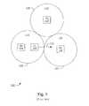
- FIG. 1depicts a typical distributed voice and/or data network topology, in accordance with the prior art.
- a number of base stations 102 , 104 , and 106are distributed geographically, such that each provides a cell coverage area (or simply cell) 112 , 114 , and 116 , respectively.
- the cells 112 , 114 , and 116each has an associated cell boundary 118 , 120 , and 122 , respectively, simplistically depicted circularly in FIG. 1 .
- a user terminal 108 shown in cell 114moves in a direction 110 away from the base station 104 and toward the base station 106 and its associated cell boundary 122 , handover will typically take place—i.e., the user terminal's active communication session will transfer to the new base station 106 .
- the useris, for example, exchanging data with a device coupled to the internet (which in turn is coupled to the base stations shown in the network 100 of FIG. 1 )
- such exchangewill not be interrupted due to the user terminal's movement away from the cell coverage of one station; the exchange or session will be handed over to another base station.
- Handover schemesare typically based on optimizing a cost function (C) that depends on one or more parameters, such as the received signal strengths (RSSI) from one or more base stations within the communication range of the user terminal, or visa versa, at a given time.
- Ccost function
- the schemecan be implemented by the user terminal, the base station, or a combination thereof.
- Most common schemesinvolve user terminal-centric handover, i.e., measurements (e.g., RSSI) made by the UT are solely used in the handover cost function.
- the user terminalperiodically samples transmissions (e.g., the broadcast message(s)) from a set of base stations, including any with which it is in active communication, and optimizes the cost function to select the best base station.
- the handover cost function Cusually should include a margin, sometimes known as a hysteresis margin.
- C( S A ⁇ S i ) +h, (1)
- his the hysteresis (sometimes also referred to as the hysteresis margin or factor)
- S Ais the RSSI of the current (or also sometimes referred to as the active) base station
- S iis the RSSI of an ith candidate base station.
- the hysteresis margin his included in the cost function to prevent the user terminal from frequent “ping ponging” between two or more base stations due to the power fluctuations of their transmissions. This particular need for h is further illustrated and described in connection with FIG. 2 .
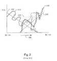
- FIG. 2is a graphical representation of the theoretical and practical signal strengths of two base stations experienced by a user terminal as the user terminal moves away from one of the base stations with which it is in active communication and toward the other base station.
- the signal strength of each base station's transmissions as received at the user terminal 108is represented by the vertical axis as a function of distance as the user terminal 108 moves with a velocity 110 away from base station 104 and toward base station 106 .
- the pathloss associated with the base stations 104 and 106could be represented by the lines 204 and 206 , respectively, in which case there would be no need for h.
- the two lines cross and the RSSI associated with base station 106exceeds that associated with the base station 104 , handover to base station 106 can occur smoothly without the ping pong effect alluded to above.
- some prior techniquesselect a relatively large h to use in the handover cost function C.
- the hysteresis factor his fixed at too large a value, then communication quality may degrade too much before handover takes place.
- the hysteresisis too small, then there may still exist a potential for the above-described ping pong effect to occur.
- the behavior of the pathloss lines 202 and 208show that (1) if h is fixed value that is selected too small, it will likely contribute to an undesired ping pong effect and (2) if h is fixed value that is selected to be too large, handover may be delayed until communication quality degrades beyond a desirable level.
- some handover techniquesuse a variable measuring window in which to take signal strength measurements, and then change the window length relative to the calculated velocity of the user terminal.
- This techniquesuffers from drawbacks.
- estimating the velocity of the user terminalis a relatively difficult task.
- using a variable window lengthrenders implementation, for example in a digital signal processor (DSP), impractical since buffers need to change.
- DSPdigital signal processor
- Ccost function
- the present inventionprovides a method and apparatus for facilitating initial base station selection and/or handover (collectively referred to herein as base station selection).
- base station selectionis adaptively determined as a function of the variance of receive signal strength.
- an adaptive hysteresis factorcan be obtained and used for a subsequent handover decision, for example, based on a cost function that takes into account the hysteresis.
- base station selectiontakes into account a set of one or more selection criteria (e.g., distance and base station load) in addition to signal strength and hysteresis information to select a base station.
- FIG. 1depicts a typical distributed voice and/or data network topology, in accordance with the prior art
- FIG. 2is a graphical representation of the theoretical and practical signal strengths of two base stations experienced by a user terminal as the user terminal moves away from one of the base stations with which it is active communication and toward the other base station;
- FIG. 3is a flow diagram of a method for adaptively computing a hysteresis factor for facilitating base station selection, according to one embodiment of the invention
- FIG. 4is a flow diagram of a method for computing signal strength fluctuation for a received signal (e.g., as received by a user terminal from a transmitting base station), in accordance with one embodiment of the invention
- FIG. 5is a flow diagram of a method for computing hysteresis as a function of the estimate of fluctuation in received signal strength for two or more base stations, in accordance with one embodiment of the invention
- FIG. 6is a flow diagram of a method for selecting a base station for handover, in accordance with one embodiment of the invention.
- FIG. 7is a flow diagram of a method for performing initial cell selection, in accordance with one embodiment of the invention.
- FIG. 8Ais a block diagram of a user terminal that includes a base station selection mechanism, in accordance with one embodiment of the invention.
- FIG. 8Bis a block diagram of the processing unit of the user terminal depicted in FIG. 8A , in accordance with one embodiment of the invention
- FIG. 9is a block diagram of a base station that may be employed in a wireless communication system employing an embodiment of the invention.
- the present inventionprovides a method and apparatus for facilitating initial base station selection and/or handover (collectively referred to herein as base station selection).
- base station selectionis adaptively determined as a function of the variance of receive signal strength.
- an adaptive hysteresis factorcan be obtained and used for a subsequent handover decision, for example, based on a cost function that takes into account the hysteresis.
- base station selectiontakes into account a set of one or more selection criteria (e.g., distance and base station load) in addition to signal strength and hysteresis information to select a base station.
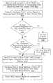
- FIG. 3is a flow diagram of a method for adaptively computing a hysteresis factor for facilitating base station selection, according to one embodiment of the invention.
- the method shown in FIG. 3is performed exclusively by the user terminal. It will be appreciated to those skilled in the art, however, that the invention can be modified to allow the method to be performed in conjunction with one or more base station(s) as well.
- a first value representing the fluctuation in signal strength (e.g., RSSI) for a first base stationis computed.
- a second value representing the fluctuation in signal strength for a second base stationis computed.
- the first and second valuesare combined to obtain a hysteresis factor associated with the first and second base stations.
- the process from blocks 302 through block 306is repeated for all “candidate” base stations (i.e., those base stations whose transmissions the user terminal can “hear” above a certain threshold) and a handover cost function C for each candidate base station is computed.
- handoveris performed for any candidate base station whose cost function is optimized.
- the handoveris not based solely on the cost function (which in turn is based on hysteresis and relative receive signal strengths), but also is based on other base station selection criteria, e.g., estimated distance to, load of, and relative difference of cost functions.
- the first and second values computed at blocks 302 and 304represent the signal strength fluctuation for first and second base stations, respectively.
- the first base stationfor example, may be a “current” or “active” base station; that is, one with which the user terminal is actively registered and in communication, and the second base station may be a candidate base station.
- both first and second base stationsmay represent candidate base stations, e.g., in the case of initial base station selection; that is, when the user terminal is not actively in communication with a particular base station but rather is searching for an active base station, e.g., upon power-up of the user terminal.
- FIG. 4is a flow diagram of a method for computing signal strength fluctuation for a received signal, in accordance with one embodiment of the invention.
- the large scale pathloss component of the received signalis estimated.
- the large scale pathloss component for the base station 104 's signal as received by the user terminal 108is depicted by the line 204 , which essentially changes as the user terminal moves toward or away from a given base station.
- the large scale pathlossis estimated by averaging the received signal over a relatively large interval (i.e., one that includes a relatively large number of samples).
- averagingintroduces a delay in response (e.g., for performing handover) that is proportional to the averaging window length
- the inventionsamples the broadcast transmission of each candidate base station every 0.5 seconds using a fixed-size sliding rectangular window spanning 25 seconds (equal to 50 samples).
- the large scale pathloss component computed at block 402is removed from a representation (which in one embodiment involves smoothing) of the small scale received signal strength from that base station to obtain an intermediate residual signal.
- sharp changesare removed from the power envelope using a fixed-size short term averaging window that spans 5 seconds (or 10 samples), given a base station broadcast sampling duration of 0.5 seconds. In an alternative embodiment, no short term averaging is performed.
- the fluctuation of the residual signalis estimated by computing the standard deviation ⁇ of the residual signal r in a recursive manner as follows:
- ⁇is set to 0.1 to provide exponential weighting that emphasizes relatively recent samples over older ones.
- ⁇can be set to 1/N, where N is the number of samples, in which case the memory of the system is infinite and all samples are given equal weighting in the computed estimate of the fluctuation.
- ⁇can be selected from a variety of values to suit particular implementations of the invention.
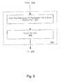
- FIG. 5is a flow diagram of a method for computing hysteresis as a function of the estimate of fluctuation in received signal strength for two or more base stations, in accordance with one embodiment of the invention.
- the estimates of fluctuation in received signal strength for a base station pairare summed.
- the base station pairin one embodiment, represents an active base station and a candidate base station.
- the receive signal strength fluctuation associated with a particular base station pairis computed using equation 3 above.
- the signal strength fluctuationis estimated and represented by the standard deviation of signal strength over one or more fixed-length averaging windows.
- the sum obtained at block 502is scaled by a scaling factor to obtain the hysteresis for the base station pair.
- the scaling factor mmay be obtained through simulation appropriate for a particular communication system architecture and network in which the invention is implemented. In one embodiment of the invention, a scaling factor of m equal to a value between 1.5 and 2 is used. In alternative embodiments, particular network simulations may indicate a different range of values for m. As such, should the invention is not limited to the range of values for m described with reference to one particular embodiment of the invention. Criteria for Base Station Selection
- received signal strength and hysteresise.g., as provided by the cost function C
- other base station selection criteriasuch as base station load and estimated distance thereto
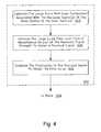
- FIG. 6is a flow diagram of a method for selecting a base station for handover, in accordance with one embodiment of the invention.
- a (receiving) user terminalmeasures the RSSI for a set of candidate base stations (i.e., those whose RSSI are above a given architecturally-specified threshold) and compiles a list of candidate base stations based on the measured RSSI's, where the largest RSSI appears at the top of the list as indicative of the most likely candidate base station for handover.
- a handover cost functionis computed based on received signal strength and hysteresis for one or more base station pairs, wherein one of the base station pairs is the currently active base station and the other is the most likely candidate base station (in one embodiment, the one having the largest RSSI) from the list derived at block 600 .
- the cost functionin one embodiment of the invention, is represented by the following equation:
- his the hysteresis (sometimes also referred to as the hysteresis margin or factor)
- S Ais the RSSI of the current (or also sometimes referred to as the active) base station
- S iis the RSSI of an ith candidate base station, beginning with the one having the largest RSSI relative to the other (remaining) candidate base stations in the list.
- load information for that candidate base stationis compared to a threshold. For example, in one embodiment, if for any candidate base station load exceeds a maximum load threshold, then at block 610 that candidate base station is eliminated as such from being a potential handover base station candidate.
- each base stationindicates its load information in a broadcast burst it transmits periodically.
- the base station having the most negative value for C iis at the top of the list of candidate base stations as the most likely candidate base station BS i for handover/selection.
- one or more base station selection criteria of the most likely candidate base station BS iis compared with the other candidate base stations BS j .
- the comparisonis performed in accordance with the ordering of C i , beginning with the smallest value(s) for C first.
- the criteriaincludes load, distance, and if applicable, also relative signal strength and hysteresis as provided by the cost function C.
- base stations in a communication networktransmit broadcast messages in a synchronized manner according to a common timing reference.
- the common timing referencein one embodiment, is a precise reference time derived from Global Positioning Satellite (GPS) system.
- GPSGlobal Positioning Satellite
- the user terminalcan monitor a set of (candidate) base stations to determine a relative time-of-arrival between the transmissions of those base stations, and in particular, their broadcast messages.
- the user terminalobtains from the current base station an indication of the propagation delay ( ⁇ ) based on the current base stations' measurement of time-of-arrival of uplink signals from the user terminal relative to the broadcast messages the base station transmitted. From the propagation delay ( ⁇ ), the user terminal can compute the true distances to both the current base station and the other (candidate) base stations.
- distancecan be computed based on time stamping of messages, for example, if both the base stations and user terminals are synchronized to a GPS clock and then measure time-of-arrival of messages and compare those to the time stamp included in such messages.
- BS iis selected at block 616 as the current base station.
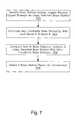
- FIG. 7is a flow diagram of a method for performing initial cell selection, in accordance with one embodiment of the invention.
- Initial cell selectionoccurs when there is no current base station with which a user terminal is in active communication of traffic information; e.g., initial cell selection can occur when a user terminal powers up to register and “enter” a network and is searching for an optimum base station to be selected as a current/active base station.
- the method of initial cell selectionis similar to that described for handover with reference to FIG. 6 , except that hysteresis is set for zero.
- the base station having the largest receive signal strength(e.g., as provided by RSSI at the user terminal) is identified.
- all base stations the user terminal can “hear”e.g., those having RSSI above a system-defined threshold at the user terminal
- any base station(s) with load larger than a thresholdare eliminated from the list of candidate base stations.
- the thresholdis set to maximum.
- the load of the most likely base station, BS iis compared—in descending order of relative RSSI or other signal strength indicator—to the set of one or more remaining candidate base stations BS j using the following condition: l j ⁇ l i /2. (8) In one embodiment, the comparison is done using base station pairs in the order of the list, beginning with the largest relative RSSI values.
- BS iis selected at block 708 as the current base station.
- FIGS. 8-9depict some, not all, exemplary architectures for communication devices that may employ the method and apparatus of the present invention in accordance with one or more embodiments of the invention.
- the present inventionrelates to wireless communication systems that may provide fixed-access or mobile-access voice and/or data communications over the air.
- Such systemsmay use spatial division multiple access (SDMA) technology in combination with multiple access protocols, such as time division multiple access (TDMA), frequency division multiple access (FDMA) and code division multiple access (CDMA).
- SDMAspatial division multiple access
- TDMAtime division multiple access
- FDMAfrequency division multiple access
- CDMAcode division multiple access
- Multiple accesscan be employed with frequency division duplex (FDD) or time division duplex (TDD).
- FDDfrequency division duplex
- TDDtime division duplex
- TDDtime division duplex
- TDDtime division duplex
- TDDtime division duplex
- TDDtime division duplex
- FIG. 8Ais a block diagram of a user terminal that includes a base station selection mechanism, in accordance with one embodiment of the invention.
- a user terminal 800includes an antenna 802 (which may include one or more—i.e., an array—of antenna elements), coupled to a radio unit 804 for transmitting and receiving RF signals with one or more base stations, such as the one shown in FIG. 9 .
- the radio unit 804includes transmitter and receiver mechanisms, and will typically include one or more power amplifiers, LNA's, up/down converters, digital-to-analog and analog-to-digital converters, etc., for receiving signals over the air and providing them (typically after some down conversion) to a processing unit 806 coupled thereto, and similarly, up-converting baseband signals provided by the processing unit 806 and transmitting them, e.g., to a selected base station.
- the processing unit 806includes storage areas and processing circuitry for processing signals received or to be transmitted by the radio unit 804 via the antenna 802 of the user terminal 800 .
- a high level controller 808shown coupled to the processing unit 806 , can be, in one embodiment of the invention, further coupled to an external end user data processing device 810 .
- the user terminal 800in one embodiment, represents a wireless modem (e.g., as embodied in a PCMCIA form factor) that may be coupled to/integrated with the device 810 , which may represent a laptop computer, PDA, gaming or other data processing device.
- the high level controller 808may receive user selected data to provide to the processing unit 806 , which may in turn process the data (e.g., code it, modulate it, etc., in accordance with a particular wireless communication protocol), and provide the processed signals to the radio unit 804 to be transmitted to an active base station.
- the processing unit 806may process the data (e.g., code it, modulate it, etc., in accordance with a particular wireless communication protocol), and provide the processed signals to the radio unit 804 to be transmitted to an active base station.
- the processing unit 806in accordance with one embodiment of the invention, includes a storage area (not shown) that stores machine-executable instructions that, when executed, cause the processing unit 806 to perform one or more of the methods of the present invention.
- the user terminal 800may represent a voice processing radio unit, for example for a digital mobile/cellular telephone.
- FIG. 8Bis a block diagram of the processing unit of the user terminal depicted in FIG. 8A , in accordance with one embodiment of the invention.
- the processing unitreceives transmitted signals from one or more base stations which are provided as input to a received signal strength measurement (RSSI) unit 820 .
- the signal received from a particular base stationis a broadcast message burst that includes (1) an indication of the load (e.g., the number user terminals actively communicating with that base station or alternatively, an indication of whether the load is or is not above a threshold); and (2) an indication of propagation delay, from which distance to the base station can be derived by a distance calculation unit 826 .
- the output of the distance calculation unit 826namely, the estimated distance between the user terminal and the base station—is provided to a base station selection unit 824 , as is the load information and the output of the RSSI unit 820 .
- the output of the RSSI unit 820is also provided to a hysteresis calculation unit 822 .
- the hysteresis calculation unit 822in one embodiment, adaptively calculates hysteresis for use in a handover cost function, in accordance with a method of the invention as described herein. In an alternative embodiment, however, the hysteresis calculation unit may provide a hysteresis factor using one or a combination of other methods.
- the base station selection unit 824uses the input hysteresis factor (if any), an indication of received signal strength as provided by the RSSI unit 820 , as well as the load information and distance information, selects a base station, either initially or for handover, in accordance with a described method of the present invention.
- FIG. 9is a block diagram of a base station that may be employed in a wireless communication system employing an embodiment of the invention.
- a system 920which may be part of a base station, in one embodiment, includes an antenna array 922 , which in turn includes a number of antenna elements.
- the antenna array 922is utilized for transmitting downlinks signals to one or more remote user terminals and for receiving uplinks signals from the one or more remote user terminals.
- the antenna array 922also transmits a broadcast message that indicates information about the base station, including, for example, an indication of reference time of transmission of the broadcast message (from which a receiving user terminal can estimate distance to the base station), an indication of the load of the base station, and in one embodiment, an indication of the transmit power the base station uses to transmit the message.
- the system 920may communicate with several remote user terminals, and as such, may process a number of signals each associated with a remote user terminal or other signal source.
- the system 920may be employed in each of several base stations in a wireless communication network, where each base station uses a given set of channels to communicate with remote user terminal units within a given geographic region, e.g., a cell.
- Such remote user terminalsmay be stationary or mobile, and may communicate voice and/or data with the system 920 using PPP, TC/IP and/or other data or voice protocols.
- each such remote user terminalis coupled to an external data processing device (e.g., a laptop computer, a PDA, a gaming device or other computing device) using an Ethernet or PPP-over-Ethernet (PPPOE) connection to allow such device to exchange data with the system 920 vis-à-vis a wireless communication link established between the user terminal and the system 920 .
- an external data processing devicee.g., a laptop computer, a PDA, a gaming device or other computing device
- PPP-over-Ethernet (PPPOE) connectionto allow such device to exchange data with the system 920 vis-à-vis a wireless communication link established between the user terminal and the system 920 .
- each antenna element of the antenna array 922is coupled to a power amplifier (PA) and low-noise amplifier (LNA) 924 .
- the PA/LNA 924 of each antenna elementamplifies the received (uplink) and/or transmitted (downlink) signal(s).
- each PA/LNA 924is coupled to a down-converter 926 and an up-converter 928 .
- the down-converter 926converts the “raw” signal received by the antenna array 922 on a carrier frequency into a receive (Rx) baseband signal, which is provided to a baseband processor (also referred to as a modem board) 930 .
- Rxreceive
- the up-converter 928conversely, converts a transmit (Tx) baseband signal provided by the baseband processor 930 into a carrier frequency transmit signal, which is provided to the PA/LNA 924 to be transmitted (e.g., to a remote user terminal).
- ADCanalog-to-digital conversion
- DACdigital-to-analog circuitry
- the baseband processor 930typically includes hardware (e.g., circuitry) and/or software (e.g., machine-executable code/instructions stored on a data storage medium/device) to facilitate processing of received (uplink) and transmitted (downlink) signals.
- the baseband processor 930includes at least one narrow-band filter 936 filter to filter received signals either in analog or digital form.
- the filtered signal from the narrow-band filter 936is provided to a spatial processor 938 .
- the spatial processor 938typically includes at least one general purpose processor and/or digital signal processor (DSP) to facilitate spatial processing.
- the spatial processor 938based on the spatial or spatio-temporal characteristic(s) (also known as a “spatial signature”) of one or more uplink signals, is able to transmit and receive signals between one or more remote user terminals in a spatially selective manner.
- the spatial channels and SDMAmay simultaneously receive and/or transmit on the same channel (e.g., carrier frequency and/or time slot and/or code) but may be distinguishable by the system 920 based on their unique spatial or spatio-temporal characteristic(s).
- spatial channelsmay not be employed.
- a spatial characteristicis direction of arrival (DOA) or angle of arrival (AOA).
- DOAdirection of arrival
- AOAangle of arrival
- Other types of spatial characteristics known in the art of adaptive arraysmay be employed in conjunction with the present invention.
- the antenna array 922facilitates transfer of signals between the system 920 and a desired remote user terminal and/or one or more other devices (e.g., a plurality of remote user terminals, other base stations in a wireless communication network, a satellite communication network, etc.).
- the antenna arraymay transmit downlink signals to the desired remote user terminal, and receive uplink signals from the remote user terminal.
- Such transmission and receptionmay occur in the same frequency channel but at different times (e.g., in a TDD system) or may occur at different frequencies (e.g., in an FDD) system.
- the processor 938determines the spatial characteristic(s) of the uplink signal from the desired remote user terminal, also referred to herein as a primary remote user terminal, as well as the spatial characteristic(s) of one or more other non-primary remote user terminals. Based on such characteristics, the system 920 determines a downlink beamforming strategy to enhance its transmission gain at the location of the desired remote user terminal, while relatively minimizing its transmission gain (i.e., providing a “null” or interference mitigated region) at the location of the non-primary remote user terminal(s). Similarly, the system 920 , based on the spatial characteristics, may perform uplink beamforming to enhance its reception gain from the location of the primary remote user terminal, while minimizing its reception gain from the location(s) of one or more non-primary remote user terminals.
- the system 920supports spatial channels, such that two or more remote user terminals in communication with the system 920 may simultaneously employ the same conventional frequency and/or time channel. In alternative embodiments, however, spatial channels may not be supported or utilized or may be utilized only when one or more conditions are met.
- the spatial processor 938is further coupled to a demodulator and error control unit 940 , which receives an “extracted” or “desired” signal or set of signals from the spatial processor 938 , and outputs the extracted signal to a network processor 932 .
- the unit 940may perform error correction, provide packet overhead, and/or perform other processing before outputting the uplink information in the form of digital data to the network processor 932 .
- the network processor 932which may or may not constitute part of the system 920 , facilitates the transfer of information between the system 920 and an external network 934 , which, for example, may represent the Internet, in which case the system 920 may be coupled (through wireless and/or wired links) to an Internet Service Provider (ISP).
- ISPInternet Service Provider
- Such informationmay include voice and/or data and may be transferred in a packet-switched or circuit-switched manner.
- a remote user terminalmay include a cellular telephone, two-way pager, PDA with wireless communication capability, a wireless modem that may be interfaced to a data processing device, such as a laptop computer, PDA, gaming device or other computing device, or other communication device to facilitate routing voice and/or data signals between the remote user terminal(s) and the network 934 , which in this example may include the public switched telephone network (PSTN), the Internet, and/or other voice and/or data network.
- PSTNpublic switched telephone network
- the Internetand/or other voice and/or data network.
- the remote user terminalmay include or be interfaced with a computing device (e.g., a portable digital assistant, a laptop/notebook computer, a computing cellular telephone handset, etc.), along with a Web-browser, in which case the network 934 may represent the Internet and the network interface processor may facilitate communication between the remote user terminal (via the system 920 ) and one or more servers or other data processing systems coupled to the Internet.
- voice and/or datae.g., video, audio, graphics, text, etc.
- voice and/or datamay be transferred between the system 20 (and one or several remote user terminals in communication therewith) and an external network 934 .
- base stationdenotes a voice or data access point of wireless communication system that serves user terminals in a given geographical area.
- a base stationmay be an access point of a cellular-type voice (and/or data) communication system.
- the base stationmay represent an access point of an IEEE 802.X standard-based data communication network (e.g., 802.11, 802.16, 802.20, etc.).
- IEEE 802.Xstandard-based data communication network
- FIGS. 8-9may be implemented by hardware, software or combination thereof, as will be apparent to those skilled in the art.
- the elements in FIGS. 8-9may be embodied in machine-executable instructions, which may be used to cause a general-purpose or special-purpose processor or logic circuits programmed with the instructions, to perform the method(s) of the present invention.
- the elements in FIGS. 8-9may be implemented by logic or analog circuits to perform the method(s) of the present invention or with a combination of such circuits with machine-executable instructions (i.e., software).
- the present inventionin one embodiment is provided as a computer program product which may include a machine-readable medium having stored thereon instructions which may be used to program a computer (or other electronic devices) to perform a process according to the present invention.
- the machine-readable mediummay include, but is not limited to, floppy diskettes, optical disks, CD-ROMs, and magneto-optical disks, ROMs, RAMs, EPROMs, EEPROMs, magnet or optical cards, flash memory, or other type of media or machine-readable medium suitable for storing electronic instructions.
- the present inventionmay also be downloaded as a computer program product, wherein the program may be transferred from a remote computer to a requesting computer by way of data signals embodied in a carrier wave or other propagation medium via a communication link (e.g., a modem or network connection).
- a communication linke.g., a modem or network connection
- the present inventionhas been described in the context of a wireless internet data system for portable handsets or other user terminal devices (e.g., wireless modems that may be interfaced with various portable data processing devices), it can be applied to a wide variety of different wireless systems in which data is exchanged. Such systems include voice, video, music, broadcast and other types of data systems without external connections.
- the present inventioncan be applied to fixed user terminals as well as to low and high mobility terminals. Many of the methods are described herein in a basic form but steps can be added to or deleted from any of the methods and information can be added or subtracted from any of the described messages without departing from the basic scope of the present invention. It will be apparent to those skilled in the art that many further modifications and adaptations can be made. The particular embodiments are not provided to limit the invention but to illustrate it. The scope of the present invention is not to be determined by the specific examples provided above but only by the claims below.
Landscapes
- Engineering & Computer Science (AREA)
- Computer Networks & Wireless Communication (AREA)
- Signal Processing (AREA)
- Physics & Mathematics (AREA)
- Electromagnetism (AREA)
- Quality & Reliability (AREA)
- Computer Security & Cryptography (AREA)
- Mobile Radio Communication Systems (AREA)
Abstract
Description
C=(SA−Si)+h, (1)
where h is the hysteresis (sometimes also referred to as the hysteresis margin or factor), SAis the RSSI of the current (or also sometimes referred to as the active) base station, and Siis the RSSI of an ith candidate base station. When C<0, then handover should be initiated.
- For k=1, 2, . . . N
r(k)=s[k−(L1−L2)/2]−l(k), (2) - and
Γ(k,i)=√{square root over ((1−α)Γk-12+αrk2)} (3)
where r(k) represents the residual signal; s and l are the short and long term averaged signals, respectively (though in another embodiment, there is no short term averaging). L1 and L2 are the lengths of the long and short averaging windows, respectively; α is the memory factor; and Γ(k,i)is the (estimated) standard deviation of the averaged signal strength fluctuation (or “power envelope”) of the ith base station at time instant k; and N is the number of samples used in the above computation.
- For k=1, 2, . . . N
h=m*(ΓA+ΓC) (4)
where m is the scaling factor, ΓAis the estimated standard deviation of the signal strength fluctuation for the current (active) base station and ΓCis the estimated standard deviation of the signal strength fluctuation for the candidate base station. The scaling factor m may be obtained through simulation appropriate for a particular communication system architecture and network in which the invention is implemented. In one embodiment of the invention, a scaling factor of m equal to a value between 1.5 and 2 is used. In alternative embodiments, particular network simulations may indicate a different range of values for m. As such, should the invention is not limited to the range of values for m described with reference to one particular embodiment of the invention.
Criteria for Base Station Selection
lj<li/2 (5)
and
dj<di/2 (6)
both do not hold true, where ljis the load of the jth candidate base station, liis the load of BSi, djis the distance to the jth candidate base station, and diis the distance to BSi, then BSiis selected at
(Ci−Cj)<3 dB (7)
then the jth base station is selected as the current base station; i.e., handover will take place to the jth base station. Otherwise, BSiis selected as the current base station.
lj<li/2. (8)
In one embodiment, the comparison is done using base station pairs in the order of the list, beginning with the largest relative RSSI values.
(Si−Sj)<3 dB (9)
holds true, where Siis the RSSI of BSiand SjRSSI of BSj, then the jth base station is selected; otherwise, BSiis selected as the current base station.
Hardware Overview
Claims (22)
Priority Applications (3)
| Application Number | Priority Date | Filing Date | Title |
|---|---|---|---|
| US10/606,428US6954643B2 (en) | 2003-06-25 | 2003-06-25 | Criteria for base station selection, including handover, in a wireless communication system |
| JP2006517120AJP4571629B2 (en) | 2003-06-25 | 2004-05-13 | Criteria for base station selection including handover in wireless communication systems |
| PCT/US2004/015373WO2005006781A2 (en) | 2003-06-25 | 2004-05-13 | Criteria for base station selection, including handover, in a wireless communication system |
Applications Claiming Priority (1)
| Application Number | Priority Date | Filing Date | Title |
|---|---|---|---|
| US10/606,428US6954643B2 (en) | 2003-06-25 | 2003-06-25 | Criteria for base station selection, including handover, in a wireless communication system |
Publications (2)
| Publication Number | Publication Date |
|---|---|
| US20040266474A1 US20040266474A1 (en) | 2004-12-30 |
| US6954643B2true US6954643B2 (en) | 2005-10-11 |
Family
ID=33540053
Family Applications (1)
| Application Number | Title | Priority Date | Filing Date |
|---|---|---|---|
| US10/606,428Expired - Fee RelatedUS6954643B2 (en) | 2003-06-25 | 2003-06-25 | Criteria for base station selection, including handover, in a wireless communication system |
Country Status (3)
| Country | Link |
|---|---|
| US (1) | US6954643B2 (en) |
| JP (1) | JP4571629B2 (en) |
| WO (1) | WO2005006781A2 (en) |
Cited By (37)
| Publication number | Priority date | Publication date | Assignee | Title |
|---|---|---|---|---|
| US20040267928A1 (en)* | 2003-06-25 | 2004-12-30 | Paul Petrus | Adaptive determination of hysteresis for facilitating base station selection, including handover, in a wireless communication system |
| US20050046613A1 (en)* | 2002-01-21 | 2005-03-03 | Nokia Corporation | Provision of location information |
| US20050176440A1 (en)* | 2004-02-06 | 2005-08-11 | Nec Laboratories America, Inc. | Load-aware handoff and site selection scheme |
| US20050239466A1 (en)* | 2004-04-02 | 2005-10-27 | Doru Calin | Methods and devices for varying a hand-off base station list based on traffic conditions |
| US20070037550A1 (en)* | 2005-04-29 | 2007-02-15 | Frederic Rassam | System and process for switching between cell phone and landline services |
| US20070160007A1 (en)* | 2006-01-11 | 2007-07-12 | Li-Chun Wang | Method and device for cost-function based handoff determination using wavelet prediction in vertical networks |
| US20070160017A1 (en)* | 2006-01-09 | 2007-07-12 | Cisco Technology, Inc. | Seamless roaming for dual-mode WiMax/WiFi stations |
| US20070253319A1 (en)* | 2006-04-27 | 2007-11-01 | Kaj Jansen | Signal detection in OFDM system |
| US20070254594A1 (en)* | 2006-04-27 | 2007-11-01 | Kaj Jansen | Signal detection in multicarrier communication system |
| US20090305654A1 (en)* | 2008-06-04 | 2009-12-10 | Research In Motion Limited | System and methods for determining radiated radio frequency (rf) receiver sensitivity |
| US7693521B1 (en)* | 2004-08-04 | 2010-04-06 | Sprint Spectrum L.P. | Method and system for mobile station handoff |
| US7894816B1 (en) | 2005-03-16 | 2011-02-22 | Sprint Spectrum L.P. | Method of selecting carrier frequency for call origination |
| US20110274083A1 (en)* | 2010-05-04 | 2011-11-10 | Nokia Corporation | Method and Apparatus for Admission Control and Forced Handover in a Multi-Layer Network Configuration |
| US8315326B2 (en) | 2000-06-13 | 2012-11-20 | Aloft Media, Llc | Apparatus for generating at least one signal based on at least one aspect of at least two received signals |
| KR101242174B1 (en) | 2006-10-10 | 2013-03-12 | 삼성전자주식회사 | Vertical handover method for overlay communication system |
| US8503938B2 (en) | 2004-10-14 | 2013-08-06 | Qualcomm Incorporated | Methods and apparatus for determining, communicating and using information including loading factors which can be used for interference control purposes |
| US8514771B2 (en) | 2005-12-22 | 2013-08-20 | Qualcomm Incorporated | Methods and apparatus for communicating and/or using transmission power information |
| US8514692B2 (en) | 2003-02-24 | 2013-08-20 | Qualcomm Incorporated | Methods and apparatus for determining, communicating and using information which can be used for interference control purposes |
| US8694042B2 (en) | 2005-10-14 | 2014-04-08 | Qualcomm Incorporated | Method and apparatus for determining a base station's transmission power budget |
| US8811348B2 (en) | 2003-02-24 | 2014-08-19 | Qualcomm Incorporated | Methods and apparatus for generating, communicating, and/or using information relating to self-noise |
| US8830827B2 (en) | 2005-12-22 | 2014-09-09 | Qualcomm Incorporated | Methods and apparatus for communicating transmission backlog information |
| US8965413B2 (en) | 2006-04-12 | 2015-02-24 | Qualcomm Incorporated | Locating a wireless local area network associated with a wireless wide area network |
| US9107134B1 (en) | 2011-01-12 | 2015-08-11 | Sprint Communications Company L.P. | Edge sector handoff determination |
| US9119220B2 (en) | 2005-12-22 | 2015-08-25 | Qualcomm Incorporated | Methods and apparatus for communicating backlog related information |
| US9125092B2 (en) | 2005-12-22 | 2015-09-01 | Qualcomm Incorporated | Methods and apparatus for reporting and/or using control information |
| US9125093B2 (en) | 2005-12-22 | 2015-09-01 | Qualcomm Incorporated | Methods and apparatus related to custom control channel reporting formats |
| US9137072B2 (en) | 2005-12-22 | 2015-09-15 | Qualcomm Incorporated | Methods and apparatus for communicating control information |
| US9148795B2 (en) | 2005-12-22 | 2015-09-29 | Qualcomm Incorporated | Methods and apparatus for flexible reporting of control information |
| US9191840B2 (en) | 2005-10-14 | 2015-11-17 | Qualcomm Incorporated | Methods and apparatus for determining, communicating and using information which can be used for interference control |
| US9338795B2 (en) | 2005-12-22 | 2016-05-10 | Qualcomm Incorporated | Methods and apparatus for communicating transmission backlog information |
| US9451491B2 (en) | 2005-12-22 | 2016-09-20 | Qualcomm Incorporated | Methods and apparatus relating to generating and transmitting initial and additional control information report sets in a wireless system |
| US9462604B2 (en) | 2005-12-22 | 2016-10-04 | Qualcomm Incorporated | Methods and apparatus related to selecting a request group for a request report |
| US9473265B2 (en) | 2005-12-22 | 2016-10-18 | Qualcomm Incorporated | Methods and apparatus for communicating information utilizing a plurality of dictionaries |
| US9544860B2 (en) | 2003-02-24 | 2017-01-10 | Qualcomm Incorporated | Pilot signals for use in multi-sector cells |
| US9603102B2 (en) | 2003-02-24 | 2017-03-21 | Qualcomm Incorporated | Method of transmitting pilot tones in a multi-sector cell, including null pilot tones, for generating channel quality indicators |
| US10645693B2 (en) | 2005-12-22 | 2020-05-05 | Qualcomm Incorporated | Methods and apparatus of implementing and/or using a control channel |
| US10959120B2 (en) | 2005-12-22 | 2021-03-23 | Qualcomm Incorporated | Methods and apparatus related to selecting control channel reporting formats |
Families Citing this family (52)
| Publication number | Priority date | Publication date | Assignee | Title |
|---|---|---|---|---|
| US9661519B2 (en) | 2003-02-24 | 2017-05-23 | Qualcomm Incorporated | Efficient reporting of information in a wireless communication system |
| US7181220B2 (en)* | 2003-09-24 | 2007-02-20 | Intel Corporation | Seamless roaming apparatus, systems, and methods |
| BRPI0508179B1 (en)* | 2004-03-05 | 2019-02-05 | Samsung Electronics Co Ltd | method for transferring a server mss / bs to a bwa communication system, mobile subscriber station, and server base station |
| US7415273B2 (en)* | 2004-04-09 | 2008-08-19 | Motorola, Inc. | Efficient system and method of monitoring neighboring cells in a communication system |
| US7894823B2 (en)* | 2004-06-07 | 2011-02-22 | Nokia Inc. | System for enhanced capacity and quality over WLAN |
| JP4530872B2 (en)* | 2005-02-17 | 2010-08-25 | パイオニア株式会社 | Frame for speaker device and speaker device |
| US7738882B2 (en)* | 2005-06-13 | 2010-06-15 | Toshiba America Research, Inc. | Framework of media-independent pre-authentication improvements: including considerations for failed switching and switchback |
| JP4830486B2 (en)* | 2005-12-27 | 2011-12-07 | 株式会社ナカヨ通信機 | Wireless LAN system and wireless LAN terminal |
| JP2007194755A (en)* | 2006-01-18 | 2007-08-02 | Nec Corp | Allocation system for wireless resource and method thereof, and base station used for the same, and program |
| US7505766B2 (en)* | 2006-03-01 | 2009-03-17 | Research In Motion Limited | System for determining conducted radio frequency (RF) receiver sensitivity and related methods |
| US7555295B2 (en)* | 2006-03-01 | 2009-06-30 | Research In Motion Limited | System for determining radiated radio frequency (RF) receiver sensitivity and related methods |
| US7555293B2 (en)* | 2006-03-01 | 2009-06-30 | Research In Motion Limited | System for determining RF path loss between an RF source and an RF receiver and related methods |
| ATE414358T1 (en)* | 2006-03-01 | 2008-11-15 | Research In Motion Ltd | SYSTEM AND METHOD FOR ESTIMATING DISTANCE ATTENUATION USING HYSTERESIS IN A RADIO COMMUNICATIONS SYSTEM |
| US7489905B2 (en)* | 2006-03-01 | 2009-02-10 | Research In Motion Limited | System for determining RF path loss between an RF source and an RF receiver with hysteresis and related methods |
| US7555294B2 (en)* | 2006-03-01 | 2009-06-30 | Research In Motion Limited | System for determining total isotropic sensitivity (TIS) and related methods |
| KR101217939B1 (en)* | 2006-08-01 | 2013-01-02 | 퀄컴 인코포레이티드 | System and/or method for providing information updates to a location server |
| KR100809260B1 (en)* | 2006-10-18 | 2008-03-03 | 포항공과대학교 산학협력단 | Method and apparatus for handover decision using context information in next generation mobile communication network |
| US8891489B2 (en) | 2007-03-19 | 2014-11-18 | Qualcomm Incorporated | Handover mechanism that exploits uplink channel quality of a target cell |
| KR100922003B1 (en) | 2007-10-12 | 2009-10-14 | 한국전자통신연구원 | Hysteresis range determination method and handover triggering method, and mobile station performing the same |
| EP2091275B1 (en) | 2008-02-15 | 2011-04-06 | Mitsubishi Electric R&D Centre Europe B.V. | Method and a device for selecting which base station has to handle a half-duplex terminal |
| EP2091274B1 (en)* | 2008-02-15 | 2010-12-22 | Mitsubishi Electric R&D Centre Europe B.V. | Method and a device for determining if a handover has to be excuted for a terminal |
| EP2091276B1 (en) | 2008-02-15 | 2011-07-06 | Mitsubishi Electric R&D Centre Europe B.V. | Method and a device for determining if a handover has to be excuted for a terminal |
| JP2009253379A (en)* | 2008-04-01 | 2009-10-29 | Canon Inc | Radio communication device and method |
| JP5173667B2 (en)* | 2008-08-11 | 2013-04-03 | 株式会社エヌ・ティ・ティ・ドコモ | User apparatus, radio base station and method |
| JP2010081543A (en)* | 2008-09-29 | 2010-04-08 | Kyocera Corp | Radio communication terminal and radio communication method |
| KR101562518B1 (en)* | 2009-01-22 | 2015-10-23 | 삼성전자주식회사 | Communication system and its femto base station connection change method |
| KR101585428B1 (en)* | 2009-04-02 | 2016-01-18 | 삼성전자주식회사 | Apparatus and method for transmitting a load indicator in a broadband wireless communication system |
| JP2010288153A (en)* | 2009-06-12 | 2010-12-24 | Denso Corp | Vehicle-mounted unit |
| US8774808B2 (en) | 2009-07-29 | 2014-07-08 | Kyocera Corporation | Radio base station and communication control method |
| JP5404355B2 (en)* | 2009-12-04 | 2014-01-29 | 京セラ株式会社 | Base station, mobile communication system, and communication load balancing method |
| KR101315854B1 (en)* | 2009-12-16 | 2013-10-08 | 한국전자통신연구원 | Handover Method in Micro Base Station |
| CN102131235A (en)* | 2010-01-15 | 2011-07-20 | 西门子公司 | A load balancing method in a wireless communication system |
| CN101808379B (en)* | 2010-04-01 | 2012-11-21 | 上海交通大学 | Network received signal intensity stability-based adaptive vertical handoff method |
| CN102238607A (en)* | 2010-04-29 | 2011-11-09 | 鸿富锦精密工业(深圳)有限公司 | Base station signal transmission system and method |
| US8301145B2 (en)* | 2010-06-24 | 2012-10-30 | Apple Inc. | Fast cell selection in a mobile wireless device |
| US8634302B2 (en)* | 2010-07-30 | 2014-01-21 | Alcatel Lucent | Apparatus for multi-cell support in a network |
| EP2453699A1 (en)* | 2010-11-15 | 2012-05-16 | ST-Ericsson SA | Enhanced handover procedure |
| JP5742929B2 (en)* | 2011-03-17 | 2015-07-01 | 富士通株式会社 | DATA DISTRIBUTION CONTROL DEVICE, DATA DISTRIBUTION SYSTEM, AND DATA DISTRIBUTION CONTROL METHOD |
| KR101105848B1 (en)* | 2011-04-14 | 2012-01-13 | 한국과학기술원 | A mobile terminal including a sensor, a wireless network system including the same, and a scanning method of a wireless network system |
| US9148846B2 (en)* | 2011-06-30 | 2015-09-29 | Motorola Solutions, Inc. | Methods for intelligent network selection |
| US9301130B2 (en)* | 2011-11-07 | 2016-03-29 | Intel Deutschland Gmbh | Base station, method for controlling a communication terminal, communication terminal and method for operating a communication terminal |
| CN102421166A (en)* | 2011-11-21 | 2012-04-18 | 华为技术有限公司 | A method, device and system for discovering wireless access points |
| WO2013188545A1 (en)* | 2012-06-12 | 2013-12-19 | Qualcomm Incorporated | Dynamic multi operator selection in a multiple-sims ue |
| JP6098710B2 (en)* | 2013-02-25 | 2017-03-22 | 日本電気株式会社 | Wireless terminal, wireless communication system, handover method, and program |
| GB2512377A (en)* | 2013-03-28 | 2014-10-01 | Nec Corp | Communication System |
| GB2526617A (en)* | 2014-05-30 | 2015-12-02 | Nec Corp | Communication system |
| US12114218B2 (en) | 2019-05-10 | 2024-10-08 | Telefonaktiebolaget Lm Ericsson (Publ) | Use of system response time for cell or beam (re)selection |
| US11343726B2 (en)* | 2020-08-18 | 2022-05-24 | Sequans Communications S.A. | Cell selection and handover methods |
| FR3114470B1 (en)* | 2020-09-22 | 2022-12-16 | Sagemcom Broadband Sas | METHOD FOR SWITCHING A MOBILE STATION BETWEEN TWO WIRELESS ACCESS POINTS OF A COMMUNICATION NETWORK AND ASSOCIATED CONNECTION MANAGER DEVICE. |
| US11792707B2 (en)* | 2021-03-19 | 2023-10-17 | Dish Wireless L.L.C. | Intelligent mobility in communication networks |
| US12381642B2 (en)* | 2021-12-28 | 2025-08-05 | GE Precision Healthcare LLC | Setting and dynamically adjusting a hysteresis value used to control roaming of a wireless monitoring system |
| US12200612B2 (en)* | 2022-01-18 | 2025-01-14 | GE Precision Healthcare LLC | Methods and systems for conditional scanning |
Citations (18)
| Publication number | Priority date | Publication date | Assignee | Title |
|---|---|---|---|---|
| US5067171A (en)* | 1987-03-31 | 1991-11-19 | Mitsubishi Denki Kabushiki Kaisha | Method and apparatus for hand-off of call in progress |
| US5640676A (en)* | 1995-05-11 | 1997-06-17 | Motorola, Inc. | Method for generating a handoff candidate list |
| US5754945A (en)* | 1996-01-18 | 1998-05-19 | Northern Telecom Limited | Fuzzy logic control of cellular handoff |
| US6011974A (en)* | 1997-09-23 | 2000-01-04 | Telefonaktiebolaget L M Ericsson (Publ) | Method and system for determining position of a cellular mobile terminal |
| US6112100A (en)* | 1998-01-23 | 2000-08-29 | Motorola, Inc. | Method and apparatus for synchronizing a base station in a communication system |
| US6154657A (en)* | 1997-10-21 | 2000-11-28 | Telefonaktiebolaget Lm Ericsson | Smart subdivision of base station candidates for position location accuracy |
| US20010022806A1 (en)* | 1997-03-18 | 2001-09-20 | Hideo Adachi | Base station apparatus for radiocommunication network, method of controlling communication across radiocommunication network, radiocommunication network system, and radio terminal apparatus |
| US6295451B1 (en)* | 1997-11-21 | 2001-09-25 | Kabushiki Kaisha Toshiba | Mobile communication system, base station, and base station controller |
| US20010036820A1 (en)* | 2000-04-12 | 2001-11-01 | Mo-Han Fong | Distributed buffer management in a high data rate wireless network |
| US6411662B1 (en)* | 1997-10-31 | 2002-06-25 | Sony Corporation | Communication terminal device, cellular radio communication system, and information communication method |
| US20020177444A1 (en)* | 2001-05-25 | 2002-11-28 | Ntt Docomo, Inc. | Radio communication system for reducing interferences with respect to other communication system using close frequency band |
| US6496493B1 (en)* | 1998-05-15 | 2002-12-17 | Hyundai Electronics Industries | Handoff trial method by a mobile station |
| US6564057B1 (en)* | 1998-05-08 | 2003-05-13 | Samsung Electronics, Co., Ltd. | System and method for determining a handoff target base station in a mobile communication system |
| US20040033804A1 (en)* | 2002-08-15 | 2004-02-19 | Binzel Charles Philipp | Method and apparatus for scanning for neighboring cells |
| US20040058678A1 (en)* | 2002-09-23 | 2004-03-25 | Detorbal Rene Fernand Emile | Method and apparatus for facilitating handovers for a group of mobile radios |
| US6748222B1 (en)* | 2000-11-06 | 2004-06-08 | Nortel Networks Limited | Method and system for providing load-balanced communication |
| US20040116133A1 (en)* | 2002-12-17 | 2004-06-17 | Amit Kalhan | System and method for determining when to exit an existing wireless communications coverage network |
| US6757550B1 (en)* | 1999-09-08 | 2004-06-29 | Sanyo Electric Co., Ltd. | Mobile station and base station |
Family Cites Families (8)
| Publication number | Priority date | Publication date | Assignee | Title |
|---|---|---|---|---|
| JP3204088B2 (en)* | 1996-05-10 | 2001-09-04 | 三菱電機株式会社 | Wireless communication control device and wireless communication control method |
| JPH104580A (en)* | 1996-06-14 | 1998-01-06 | Oki Electric Ind Co Ltd | Hand-off communication system |
| US6055428A (en)* | 1997-07-21 | 2000-04-25 | Qualcomm Incorporated | Method and apparatus for performing soft hand-off in a wireless communication system |
| US5999522A (en)* | 1997-11-26 | 1999-12-07 | Motorola, Inc. | Method and apparatus for determining hand-off candidates in a communication system |
| CA2316440A1 (en)* | 1999-08-31 | 2001-02-28 | Lucent Technologies Inc. | System for performing handoffs using location information for a wireless unit |
| CN1207937C (en)* | 2000-10-09 | 2005-06-22 | 诺基亚公司 | Radio resource management |
| JP3717805B2 (en)* | 2001-06-07 | 2005-11-16 | 三洋電機株式会社 | Mobile communication terminal |
| JP2003169061A (en)* | 2001-11-29 | 2003-06-13 | Infoware System Kk | Small-electric-power lan system |
- 2003
- 2003-06-25USUS10/606,428patent/US6954643B2/ennot_activeExpired - Fee Related
- 2004
- 2004-05-13JPJP2006517120Apatent/JP4571629B2/ennot_activeExpired - Fee Related
- 2004-05-13WOPCT/US2004/015373patent/WO2005006781A2/enactiveApplication Filing
Patent Citations (18)
| Publication number | Priority date | Publication date | Assignee | Title |
|---|---|---|---|---|
| US5067171A (en)* | 1987-03-31 | 1991-11-19 | Mitsubishi Denki Kabushiki Kaisha | Method and apparatus for hand-off of call in progress |
| US5640676A (en)* | 1995-05-11 | 1997-06-17 | Motorola, Inc. | Method for generating a handoff candidate list |
| US5754945A (en)* | 1996-01-18 | 1998-05-19 | Northern Telecom Limited | Fuzzy logic control of cellular handoff |
| US20010022806A1 (en)* | 1997-03-18 | 2001-09-20 | Hideo Adachi | Base station apparatus for radiocommunication network, method of controlling communication across radiocommunication network, radiocommunication network system, and radio terminal apparatus |
| US6011974A (en)* | 1997-09-23 | 2000-01-04 | Telefonaktiebolaget L M Ericsson (Publ) | Method and system for determining position of a cellular mobile terminal |
| US6154657A (en)* | 1997-10-21 | 2000-11-28 | Telefonaktiebolaget Lm Ericsson | Smart subdivision of base station candidates for position location accuracy |
| US6411662B1 (en)* | 1997-10-31 | 2002-06-25 | Sony Corporation | Communication terminal device, cellular radio communication system, and information communication method |
| US6295451B1 (en)* | 1997-11-21 | 2001-09-25 | Kabushiki Kaisha Toshiba | Mobile communication system, base station, and base station controller |
| US6112100A (en)* | 1998-01-23 | 2000-08-29 | Motorola, Inc. | Method and apparatus for synchronizing a base station in a communication system |
| US6564057B1 (en)* | 1998-05-08 | 2003-05-13 | Samsung Electronics, Co., Ltd. | System and method for determining a handoff target base station in a mobile communication system |
| US6496493B1 (en)* | 1998-05-15 | 2002-12-17 | Hyundai Electronics Industries | Handoff trial method by a mobile station |
| US6757550B1 (en)* | 1999-09-08 | 2004-06-29 | Sanyo Electric Co., Ltd. | Mobile station and base station |
| US20010036820A1 (en)* | 2000-04-12 | 2001-11-01 | Mo-Han Fong | Distributed buffer management in a high data rate wireless network |
| US6748222B1 (en)* | 2000-11-06 | 2004-06-08 | Nortel Networks Limited | Method and system for providing load-balanced communication |
| US20020177444A1 (en)* | 2001-05-25 | 2002-11-28 | Ntt Docomo, Inc. | Radio communication system for reducing interferences with respect to other communication system using close frequency band |
| US20040033804A1 (en)* | 2002-08-15 | 2004-02-19 | Binzel Charles Philipp | Method and apparatus for scanning for neighboring cells |
| US20040058678A1 (en)* | 2002-09-23 | 2004-03-25 | Detorbal Rene Fernand Emile | Method and apparatus for facilitating handovers for a group of mobile radios |
| US20040116133A1 (en)* | 2002-12-17 | 2004-06-17 | Amit Kalhan | System and method for determining when to exit an existing wireless communications coverage network |
Cited By (75)
| Publication number | Priority date | Publication date | Assignee | Title |
|---|---|---|---|---|
| US9209871B2 (en) | 2000-06-13 | 2015-12-08 | Comcast Cable Communications, Llc | Network communication using diversity |
| US9654323B2 (en) | 2000-06-13 | 2017-05-16 | Comcast Cable Communications, Llc | Data routing for OFDM transmission based on observed node capacities |
| US9106286B2 (en) | 2000-06-13 | 2015-08-11 | Comcast Cable Communications, Llc | Network communication using diversity |
| USRE45775E1 (en) | 2000-06-13 | 2015-10-20 | Comcast Cable Communications, Llc | Method and system for robust, secure, and high-efficiency voice and packet transmission over ad-hoc, mesh, and MIMO communication networks |
| US8315327B2 (en) | 2000-06-13 | 2012-11-20 | Aloft Media, Llc | Apparatus for transmitting a signal including transmit data to a multiple-input capable node |
| US9515788B2 (en) | 2000-06-13 | 2016-12-06 | Comcast Cable Communications, Llc | Originator and recipient based transmissions in wireless communications |
| US10257765B2 (en) | 2000-06-13 | 2019-04-09 | Comcast Cable Communications, Llc | Transmission of OFDM symbols |
| US9820209B1 (en) | 2000-06-13 | 2017-11-14 | Comcast Cable Communications, Llc | Data routing for OFDM transmissions |
| US9722842B2 (en) | 2000-06-13 | 2017-08-01 | Comcast Cable Communications, Llc | Transmission of data using a plurality of radio frequency channels |
| US10349332B2 (en) | 2000-06-13 | 2019-07-09 | Comcast Cable Communications, Llc | Network communication using selected resources |
| USRE45807E1 (en) | 2000-06-13 | 2015-11-17 | Comcast Cable Communications, Llc | Apparatus for transmitting a signal including transmit data to a multiple-input capable node |
| US8451929B2 (en) | 2000-06-13 | 2013-05-28 | Aloft Media, Llc | Apparatus for calculating weights associated with a received signal and applying the weights to transmit data |
| US8315326B2 (en) | 2000-06-13 | 2012-11-20 | Aloft Media, Llc | Apparatus for generating at least one signal based on at least one aspect of at least two received signals |
| US9401783B1 (en) | 2000-06-13 | 2016-07-26 | Comcast Cable Communications, Llc | Transmission of data to multiple nodes |
| US9344233B2 (en) | 2000-06-13 | 2016-05-17 | Comcast Cable Communications, Llc | Originator and recipient based transmissions in wireless communications |
| US9356666B1 (en) | 2000-06-13 | 2016-05-31 | Comcast Cable Communications, Llc | Originator and recipient based transmissions in wireless communications |
| US8451928B2 (en) | 2000-06-13 | 2013-05-28 | Aloft Media, Llc | Apparatus for calculating weights associated with a first signal and applying the weights to a second signal |
| US9197297B2 (en) | 2000-06-13 | 2015-11-24 | Comcast Cable Communications, Llc | Network communication using diversity |
| US9391745B2 (en) | 2000-06-13 | 2016-07-12 | Comcast Cable Communications, Llc | Multi-user transmissions |
| US8363744B2 (en) | 2001-06-10 | 2013-01-29 | Aloft Media, Llc | Method and system for robust, secure, and high-efficiency voice and packet transmission over ad-hoc, mesh, and MIMO communication networks |
| US20090184872A1 (en)* | 2002-01-21 | 2009-07-23 | Nokia Corporation | Provision of location information |
| US20050046613A1 (en)* | 2002-01-21 | 2005-03-03 | Nokia Corporation | Provision of location information |
| US7646337B2 (en) | 2002-01-21 | 2010-01-12 | Nokia Corporation | Provision of location information |
| US7528772B2 (en)* | 2002-01-21 | 2009-05-05 | Nokia Corporation | Provision of location information |
| US9544860B2 (en) | 2003-02-24 | 2017-01-10 | Qualcomm Incorporated | Pilot signals for use in multi-sector cells |
| US9603102B2 (en) | 2003-02-24 | 2017-03-21 | Qualcomm Incorporated | Method of transmitting pilot tones in a multi-sector cell, including null pilot tones, for generating channel quality indicators |
| US8514692B2 (en) | 2003-02-24 | 2013-08-20 | Qualcomm Incorporated | Methods and apparatus for determining, communicating and using information which can be used for interference control purposes |
| US8811348B2 (en) | 2003-02-24 | 2014-08-19 | Qualcomm Incorporated | Methods and apparatus for generating, communicating, and/or using information relating to self-noise |
| US20040267928A1 (en)* | 2003-06-25 | 2004-12-30 | Paul Petrus | Adaptive determination of hysteresis for facilitating base station selection, including handover, in a wireless communication system |
| US7389111B2 (en)* | 2003-06-25 | 2008-06-17 | Arraycomm, Llc | Adaptive determination of hysteresis for facilitating base station selection, including handover, in a wireless communication system |
| US7310526B2 (en)* | 2004-02-06 | 2007-12-18 | Nec Laboratories America, Inc. | Load-aware handoff and site selection scheme |
| WO2005076946A3 (en)* | 2004-02-06 | 2006-03-23 | Nec Lab America Inc | Load-aware handoff and site selection scheme |
| US20050176440A1 (en)* | 2004-02-06 | 2005-08-11 | Nec Laboratories America, Inc. | Load-aware handoff and site selection scheme |
| US7805142B2 (en)* | 2004-04-02 | 2010-09-28 | Alcatel-Lucent Usa Inc. | Methods and device for varying a hand-off base station list based on traffic conditions |
| US20050239466A1 (en)* | 2004-04-02 | 2005-10-27 | Doru Calin | Methods and devices for varying a hand-off base station list based on traffic conditions |
| US7693521B1 (en)* | 2004-08-04 | 2010-04-06 | Sprint Spectrum L.P. | Method and system for mobile station handoff |
| US8503938B2 (en) | 2004-10-14 | 2013-08-06 | Qualcomm Incorporated | Methods and apparatus for determining, communicating and using information including loading factors which can be used for interference control purposes |
| US7894816B1 (en) | 2005-03-16 | 2011-02-22 | Sprint Spectrum L.P. | Method of selecting carrier frequency for call origination |
| US20070037550A1 (en)* | 2005-04-29 | 2007-02-15 | Frederic Rassam | System and process for switching between cell phone and landline services |
| US7937069B2 (en) | 2005-04-29 | 2011-05-03 | Rassam Frederic | System and process for switching between cell phone and landline services |
| US8694042B2 (en) | 2005-10-14 | 2014-04-08 | Qualcomm Incorporated | Method and apparatus for determining a base station's transmission power budget |
| US8989084B2 (en) | 2005-10-14 | 2015-03-24 | Qualcomm Incorporated | Methods and apparatus for broadcasting loading information corresponding to neighboring base stations |
| US9191840B2 (en) | 2005-10-14 | 2015-11-17 | Qualcomm Incorporated | Methods and apparatus for determining, communicating and using information which can be used for interference control |
| US8514771B2 (en) | 2005-12-22 | 2013-08-20 | Qualcomm Incorporated | Methods and apparatus for communicating and/or using transmission power information |
| US9473265B2 (en) | 2005-12-22 | 2016-10-18 | Qualcomm Incorporated | Methods and apparatus for communicating information utilizing a plurality of dictionaries |
| US9125092B2 (en) | 2005-12-22 | 2015-09-01 | Qualcomm Incorporated | Methods and apparatus for reporting and/or using control information |
| US9125093B2 (en) | 2005-12-22 | 2015-09-01 | Qualcomm Incorporated | Methods and apparatus related to custom control channel reporting formats |
| US9137072B2 (en) | 2005-12-22 | 2015-09-15 | Qualcomm Incorporated | Methods and apparatus for communicating control information |
| US9148795B2 (en) | 2005-12-22 | 2015-09-29 | Qualcomm Incorporated | Methods and apparatus for flexible reporting of control information |
| US9161313B2 (en) | 2005-12-22 | 2015-10-13 | Qualcomm Incorporated | Methods and apparatus for communicating and/or using transmission power information |
| US10645693B2 (en) | 2005-12-22 | 2020-05-05 | Qualcomm Incorporated | Methods and apparatus of implementing and/or using a control channel |
| US10959120B2 (en) | 2005-12-22 | 2021-03-23 | Qualcomm Incorporated | Methods and apparatus related to selecting control channel reporting formats |
| US9893917B2 (en) | 2005-12-22 | 2018-02-13 | Qualcomm Incorporated | Methods and apparatus for communicating control information |
| US8830827B2 (en) | 2005-12-22 | 2014-09-09 | Qualcomm Incorporated | Methods and apparatus for communicating transmission backlog information |
| US9119220B2 (en) | 2005-12-22 | 2015-08-25 | Qualcomm Incorporated | Methods and apparatus for communicating backlog related information |
| US9338795B2 (en) | 2005-12-22 | 2016-05-10 | Qualcomm Incorporated | Methods and apparatus for communicating transmission backlog information |
| US9462604B2 (en) | 2005-12-22 | 2016-10-04 | Qualcomm Incorporated | Methods and apparatus related to selecting a request group for a request report |
| US9451491B2 (en) | 2005-12-22 | 2016-09-20 | Qualcomm Incorporated | Methods and apparatus relating to generating and transmitting initial and additional control information report sets in a wireless system |
| US10159006B2 (en) | 2005-12-22 | 2018-12-18 | Qualcomm Incorporated | Methods and apparatus for reporting and/or using control information |
| US8064948B2 (en) | 2006-01-09 | 2011-11-22 | Cisco Technology, Inc. | Seamless roaming for dual-mode WiMax/WiFi stations |
| US20070160017A1 (en)* | 2006-01-09 | 2007-07-12 | Cisco Technology, Inc. | Seamless roaming for dual-mode WiMax/WiFi stations |
| US20070160007A1 (en)* | 2006-01-11 | 2007-07-12 | Li-Chun Wang | Method and device for cost-function based handoff determination using wavelet prediction in vertical networks |
| US8965413B2 (en) | 2006-04-12 | 2015-02-24 | Qualcomm Incorporated | Locating a wireless local area network associated with a wireless wide area network |
| US8045927B2 (en)* | 2006-04-27 | 2011-10-25 | Nokia Corporation | Signal detection in multicarrier communication system |
| US7864884B2 (en) | 2006-04-27 | 2011-01-04 | Nokia Corporation | Signal detection in OFDM system |
| US20070254594A1 (en)* | 2006-04-27 | 2007-11-01 | Kaj Jansen | Signal detection in multicarrier communication system |
| US20070253319A1 (en)* | 2006-04-27 | 2007-11-01 | Kaj Jansen | Signal detection in OFDM system |
| KR101242174B1 (en) | 2006-10-10 | 2013-03-12 | 삼성전자주식회사 | Vertical handover method for overlay communication system |
| US8170489B2 (en) | 2008-06-04 | 2012-05-01 | Research In Motion Limited | System and methods for determining radiated radio frequency (RF) receiver sensitivity |
| US20090305654A1 (en)* | 2008-06-04 | 2009-12-10 | Research In Motion Limited | System and methods for determining radiated radio frequency (rf) receiver sensitivity |
| US8326232B2 (en) | 2008-06-04 | 2012-12-04 | Research In Motion Limited | System and methods for determining radiated radio frequency (RF) receiver sensitivity |
| US8548389B2 (en) | 2008-06-04 | 2013-10-01 | Blackberry Limited | System and methods for determining radiated radio frequency (RF) receiver sensitivity |
| US20110274083A1 (en)* | 2010-05-04 | 2011-11-10 | Nokia Corporation | Method and Apparatus for Admission Control and Forced Handover in a Multi-Layer Network Configuration |
| US8660086B2 (en)* | 2010-05-04 | 2014-02-25 | Nokia Corporation | Method and apparatus for admission control and forced handover in a multi-layer network configuration |
| US9107134B1 (en) | 2011-01-12 | 2015-08-11 | Sprint Communications Company L.P. | Edge sector handoff determination |
Also Published As
| Publication number | Publication date |
|---|---|
| JP2007521745A (en) | 2007-08-02 |
| WO2005006781A3 (en) | 2005-05-19 |
| WO2005006781A2 (en) | 2005-01-20 |
| US20040266474A1 (en) | 2004-12-30 |
| JP4571629B2 (en) | 2010-10-27 |
Similar Documents
| Publication | Publication Date | Title |
|---|---|---|
| US6954643B2 (en) | Criteria for base station selection, including handover, in a wireless communication system | |
| US7389111B2 (en) | Adaptive determination of hysteresis for facilitating base station selection, including handover, in a wireless communication system | |
| JP4579996B2 (en) | Method for controlling the output of an access packet transmitted by a mobile station in a wireless communication system, and a wireless communication system implementing the method | |
| EP2468054B1 (en) | Methods and apparatuses for reduction of interference during positioning measurements | |
| EP1233541B1 (en) | Base station and mobile station with transmission power control | |
| JP4394291B2 (en) | Method and apparatus for wireless user location update using infrastructure measurements | |
| JP4299083B2 (en) | Wireless communication apparatus and wireless communication method | |
| US20060135193A1 (en) | Rapid channel quality based power control for high speed channels | |
| EP1334633B1 (en) | Mode switching in adaptive array communications systems | |
| JP2001512950A (en) | Method and apparatus for controlling prediction parameter by loop delay | |
| US20120302172A1 (en) | Transmission Parameter Adaptation in Cooperative Signal Communication | |
| AU2966899A (en) | A method of establishing the carrier-to-interference ratio in a radio communication system and a communication device for carrying out the method | |
| US20110269481A1 (en) | Model Based Channel State Information Feedback | |
| WO2011058991A1 (en) | Wireless communication system, base station device, mobile station device, and wireless communication method | |
| US20100246476A1 (en) | Method for driving smart antennas in a communication network | |
| JP2006524470A (en) | Improvements in or related to distributed wireless devices | |
| JP2002118512A (en) | Radio data communication system | |
| JP5423582B2 (en) | Radio base station, radio parameter adjustment method | |
| JP2001111480A (en) | Wireless communication device and transmission power control method | |
| US8265635B2 (en) | Method for determining positioning accuracy based on origination and receiving terminals and positioning device and program therefor | |
| WO2003065749A1 (en) | Information transfer method, information transfer system, and base station | |
| AU745469B2 (en) | Reception method and apparatus in CDMA system | |
| US7353001B1 (en) | Method and apparatus for managing beam selection in a mobile handset | |
| JP2000078076A (en) | Wireless communication terminal device and transmission power control method | |
| JPH11284565A (en) | Wireless communication system and wireless communication method |
Legal Events
| Date | Code | Title | Description |
|---|---|---|---|
| AS | Assignment | Owner name:ARRAYCOMM INC., CALIFORNIA Free format text:ASSIGNMENT OF ASSIGNORS INTEREST;ASSIGNOR:PETRUS, PAUL;REEL/FRAME:014251/0349 Effective date:20030624 | |
| AS | Assignment | Owner name:ARRAYCOMM LLC.,CALIFORNIA Free format text:CHANGE OF NAME;ASSIGNOR:ARRAYCOMM, INC.;REEL/FRAME:017034/0620 Effective date:20051116 Owner name:ARRAYCOMM LLC., CALIFORNIA Free format text:CHANGE OF NAME;ASSIGNOR:ARRAYCOMM, INC.;REEL/FRAME:017034/0620 Effective date:20051116 | |
| AS | Assignment | Owner name:ARRAYCOMM LLC., CALIFORNIA Free format text:CORRECTIVE ASSIGNMENT TO CORRECT THE NATURE OF CONVEYANCE PREVIOUSLY RECORDED ON REEL 017034 FRAME 0620;ASSIGNOR:ARRAYCOMM, INC.;REEL/FRAME:021619/0313 Effective date:20051116 Owner name:ARRAYCOMM LLC.,CALIFORNIA Free format text:CORRECTIVE ASSIGNMENT TO CORRECT THE NATURE OF CONVEYANCE PREVIOUSLY RECORDED ON REEL 017034 FRAME 0620. ASSIGNOR(S) HEREBY CONFIRMS THE NATURE OF CONVEYANCE IS AN ASSIGNNMENT AND NOT A CHANGE OF NAME;ASSIGNOR:ARRAYCOMM, INC.;REEL/FRAME:021619/0313 Effective date:20051116 Owner name:ARRAYCOMM LLC., CALIFORNIA Free format text:CORRECTIVE ASSIGNMENT TO CORRECT THE NATURE OF CONVEYANCE PREVIOUSLY RECORDED ON REEL 017034 FRAME 0620. ASSIGNOR(S) HEREBY CONFIRMS THE NATURE OF CONVEYANCE IS AN ASSIGNNMENT AND NOT A CHANGE OF NAME;ASSIGNOR:ARRAYCOMM, INC.;REEL/FRAME:021619/0313 Effective date:20051116 | |
| AS | Assignment | Owner name:INTEL CORPORATION, CALIFORNIA Free format text:ASSIGNMENT OF ASSIGNORS INTEREST;ASSIGNOR:ARRAYCOMM LLC;REEL/FRAME:021794/0107 Effective date:20081002 Owner name:INTEL CORPORATION,CALIFORNIA Free format text:ASSIGNMENT OF ASSIGNORS INTEREST;ASSIGNOR:ARRAYCOMM LLC;REEL/FRAME:021794/0107 Effective date:20081002 | |
| FPAY | Fee payment | Year of fee payment:4 | |
| FEPP | Fee payment procedure | Free format text:PAYOR NUMBER ASSIGNED (ORIGINAL EVENT CODE: ASPN); ENTITY STATUS OF PATENT OWNER: LARGE ENTITY Free format text:PAYER NUMBER DE-ASSIGNED (ORIGINAL EVENT CODE: RMPN); ENTITY STATUS OF PATENT OWNER: LARGE ENTITY | |
| REMI | Maintenance fee reminder mailed | ||
| LAPS | Lapse for failure to pay maintenance fees | ||
| STCH | Information on status: patent discontinuation | Free format text:PATENT EXPIRED DUE TO NONPAYMENT OF MAINTENANCE FEES UNDER 37 CFR 1.362 | |
| FP | Lapsed due to failure to pay maintenance fee | Effective date:20131011 |