US6953133B2 - Pump assembly with continuous tube - Google Patents
Pump assembly with continuous tubeDownload PDFInfo
- Publication number
- US6953133B2 US6953133B2US10/406,147US40614703AUS6953133B2US 6953133 B2US6953133 B2US 6953133B2US 40614703 AUS40614703 AUS 40614703AUS 6953133 B2US6953133 B2US 6953133B2
- Authority
- US
- United States
- Prior art keywords
- piston
- chamber
- tubing
- spray nozzle
- coupled
- Prior art date
- Legal status (The legal status is an assumption and is not a legal conclusion. Google has not performed a legal analysis and makes no representation as to the accuracy of the status listed.)
- Expired - Lifetime, expires
Links
- 239000007921spraySubstances0.000claimsabstractdescription99
- 239000012530fluidSubstances0.000claimsabstractdescription48
- 238000011144upstream manufacturingMethods0.000claimsabstractdescription8
- 239000000126substanceSubstances0.000claimsdescription44
- 238000007789sealingMethods0.000claimsdescription11
- 239000000853adhesiveSubstances0.000description2
- 230000001070adhesive effectEffects0.000description2
- 230000008901benefitEffects0.000description2
- 230000000295complement effectEffects0.000description2
- 230000008878couplingEffects0.000description2
- 238000010168coupling processMethods0.000description2
- 238000005859coupling reactionMethods0.000description2
- 238000004519manufacturing processMethods0.000description2
- 230000004048modificationEffects0.000description2
- 238000012986modificationMethods0.000description2
- CBENFWSGALASAD-UHFFFAOYSA-NOzoneChemical compound[O-][O+]=OCBENFWSGALASAD-UHFFFAOYSA-N0.000description1
- 238000004880explosionMethods0.000description1
- 239000003337fertilizerSubstances0.000description1
- 239000002917insecticideSubstances0.000description1
- 239000003562lightweight materialSubstances0.000description1
- 239000007788liquidSubstances0.000description1
- 230000014759maintenance of locationEffects0.000description1
- 239000000463materialSubstances0.000description1
- 230000013011matingEffects0.000description1
- 230000007246mechanismEffects0.000description1
- 210000002445nippleAnatomy0.000description1
- 230000037361pathwayEffects0.000description1
- 239000003380propellantSubstances0.000description1
Images


Classifications
- B—PERFORMING OPERATIONS; TRANSPORTING
- B05—SPRAYING OR ATOMISING IN GENERAL; APPLYING FLUENT MATERIALS TO SURFACES, IN GENERAL
- B05B—SPRAYING APPARATUS; ATOMISING APPARATUS; NOZZLES
- B05B1/00—Nozzles, spray heads or other outlets, with or without auxiliary devices such as valves, heating means
- B05B1/30—Nozzles, spray heads or other outlets, with or without auxiliary devices such as valves, heating means designed to control volume of flow, e.g. with adjustable passages
- B—PERFORMING OPERATIONS; TRANSPORTING
- B05—SPRAYING OR ATOMISING IN GENERAL; APPLYING FLUENT MATERIALS TO SURFACES, IN GENERAL
- B05B—SPRAYING APPARATUS; ATOMISING APPARATUS; NOZZLES
- B05B9/00—Spraying apparatus for discharge of liquids or other fluent material, without essentially mixing with gas or vapour
- B05B9/03—Spraying apparatus for discharge of liquids or other fluent material, without essentially mixing with gas or vapour characterised by means for supplying liquid or other fluent material
- B05B9/04—Spraying apparatus for discharge of liquids or other fluent material, without essentially mixing with gas or vapour characterised by means for supplying liquid or other fluent material with pressurised or compressible container; with pump
- B05B9/08—Apparatus to be carried on or by a person, e.g. of knapsack type
- B05B9/085—Apparatus to be carried on or by a person, e.g. of knapsack type with a liquid pump
- B05B9/0877—Apparatus to be carried on or by a person, e.g. of knapsack type with a liquid pump the pump being of pressure-accumulation type or being connected to a pressure accumulation chamber
Definitions
- This inventionrelates to pumps and, in particular, to nonaerosol pump sprayers.
- Noncontainer pressurizing pump sprayerscommonly utilize an integral cylinder and plunger arrangement to generate pressure to expel liquid, such as insecticide and fertilizer from a container.
- Noncontainer pressurizing pump sprayersare desirable in that they do not utilize pressurized containers which must be handled carefully and at controlled temperatures to avoid the risk of explosion.
- Noncontainer pressurizing pump sprayershave a number of other advantages, including not using propellants which destroy the ozone and being relatively inexpensive.
- noncontainer pressurizing pump sprayersThere are two common varieties of noncontainer pressurizing pump sprayers: pump sprayers that are pressurized on the upstroke and pump sprayers that are pressurized on the downstroke. Pump sprayers that are pressurized on the downstroke typically utilize a return spring which biases the plunger upward after the pressurization stroke. Examples of such noncontainer pressurizing pumps can be found in U.S. Pat. Nos. 4,174,055 and 6,296,154. While these arrangements have been successful, noncontainer pressurizing pumps are still relatively complicated and expensive devices. As such, there is a general need to develop noncontainer pressuring pumps that utilize fewer parts and/or can be made out of less expensive materials.
- the present inventionincludes an apparatus and pump attachment particularly adapted to form a noncontainer pressurizing pump sprayer which overcomes the drawbacks of the prior art.
- the pump attachmentcomprises a body, a shaft, a piston, a handle and a spray nozzle.
- the bodydefines a chamber and having a first end and a second end and a wall extending between the first end and the second end.
- the shaftextends through an opening in the first end of the chamber.
- the pistonis reciprocally mounted within the chamber.
- the pistonincludes an upper surface and a lower surface and a bore extending from the upper surface to the lower surface.
- the pistonis in sealing engagement with the interior wall of the body.
- the pistonseparates the chamber into an upper portion above the upper surface of the piston and a lower portion below the lower surface of the piston.
- the handleis coupled to the piston through the shaft.
- An inlet valve at the second end of the bodyis configured to permit the flow of fluid into the chamber and restrict the flow of fluid out of the chamber.
- a biasing memberis positioned between the piston and the first end of the elongate chamber.
- the spray nozzlecomprises an actuator and a discharge outlet.
- the actuatoris coupled to a spray valve for controlling the flow of chemical from the lower portion of the chamber through the spray nozzle to the discharge outlet.
- the spray nozzleincludes a tube that extends continuously from a point upstream of the spray valve to a point downstream of the spray valve.
- the point upstream of the spray valveis in fluid communication with the lower portion of the chamber and the point downstream of the spray valve is in fluid communication with the discharge outlet.
- the pump attachmentis used in combination with a container, which defines a cavity for storing a chemical.
- a pump attachment for a containercomprising a body, a shaft, a piston, a handle and a spray nozzle.
- the bodydefines a chamber having a first end and a second end and a wall extending between the first end and the second end.
- the shaftextends through an opening in the first end of the chamber.
- the pistonis reciprocally mounted within the chamber.
- the pistonincludes an upper surface and a lower surface and a bore extending from the upper surface to the lower surface.
- the pistonis in sealing engagement with the interior wall of the body.
- the pistonseparates the chamber into an upper portion above the upper surface of the piston and a lower portion below the lower surface of the piston.
- the handlecoupled to the piston through the shaft.
- An inlet valveis at the second end of the body and is configured to permit the flow of fluid into the chamber and restrict the flow of fluid out of the chamber.
- a biasing memberlies between the piston and the first end of the elongate chamber.
- the spray nozzlecomprises a body that defines an internal channel having an inlet end, an actuator and a discharge outlet.
- the actuatoris coupled to a spray valve for controlling the flow of chemical from the lower portion of the chamber through the spray nozzle to the discharge outlet.
- a continuous piece of tubingwhich has a first end is coupled to the piston and is in fluid communication with the lower portion of the chamber and has a second end, which extends into the spray nozzle through the inlet end of the internal channel.
- the pump attachmentis used in combination with a container, which defines a cavity for storing a chemical.
- Yet another aspect of an embodiment of the present inventionis a pump attachment for a container that comprises a body defining a chamber and having a first end and a second end and a wall extending between the first end and the second end.
- a pistonis reciprocally mounted within the chamber.
- the pistonincludes an upper surface and a lower surface and a bore extending from the upper surface to the lower surface.
- the pistonis in sealing engagement with the interior wall of the body.
- the pistonseparates the chamber into an upper portion above the upper surface of the piston and a lower portion below the lower surface of the piston.
- a handleis coupled to the piston through a relatively rigid connective member.
- a continuous piece of flexible tubingwhich has a first end, is coupled to the piston and is in fluid communication with the lower portion of the chamber.
- An inlet valveis at the second end of the body.
- the inlet valveis configured to permit the flow of fluid into the chamber and restrict the flow of fluid out of the chamber.
- a biasing memberis positioned between the piston and the first end of the elongate chamber.
- a spray nozzlecomprises an actuator and a discharge outlet, which is in fluid communication with a second end of the flexible tubing. The actuator being coupled to a spray valve for controlling the flow of chemical from the lower portion of the chamber through the spray nozzle to the discharge outlet.
- the pump attachmentis used in combination with a container, which defines a cavity for storing a chemical.
- FIG. 1is side perspective view of an example embodiment of a pump attachment attached to a chemical container.
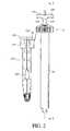
- FIG. 2is side view of the pump attachment of FIG. 1 .
- FIG. 3is a cross-sectional view taken along line 3 — 3 of FIG. 2 .
- FIG. 3Ais an enlarged view of an upper portion of FIG. 3 .
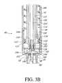
- FIG. 3Bis an enlarged view of a lower portion of FIG. 3 .
- FIG. 4is bottom view of the pump attachment of FIG. 1 .
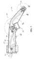
- FIG. 5is a cross-sectional view of a spray nozzle taken along line 5 — 5 of FIG. 2 .
- FIG. 5Ais an enlarged view of the central portion of the spray nozzle of FIG. 5 .
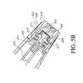
- FIG. 5Bis an enlarged view of the tip of the spray nozzle of FIG. 5 .
- FIG. 6Ais a top perspective of an actuator of the spray nozzle.
- FIG. 6Bis a front view of the actuator of FIG. 6 A.
- FIG. 6Cis a side view of the actuator of FIG. 6 A.
- FIG. 6Dis a cross-sectional view of the actuator of FIG. 6A taken along line 6 D— 6 D.
- FIG. 7is a cross-sectional view of another example embodiment of a pump apparatus.
- FIG. 8Ais a cross-sectional view taken through line 8 A— 8 A of FIG. 7 .
- FIG. 8Bis a cross-sectional view taken through line 8 B— 8 B of FIG. 8 A.
- FIG. 9is a top perspective view of an example embodiment of a spray nozzle.
- FIG. 10is a longitudinal cross-sectional view of the spray nozzle of FIG. 9 .
- FIG. 1illustrates assembly 10 that includes a container 20 and an example embodiment of a pump attachment 30 , which is also shown in FIG. 2 .
- the container 20defines an internal space or reservoir (not shown) for storing a chemical.
- the attachment 30includes a body 40 , which is inserted into the container through a port or opening.
- the attachment 30is secured to the container 20 by a threaded coupler 70 .
- the attachment 30further includes a shaft 110 which, in the illustrated embodiment, is integrally formed with or connected to a piston 130 .
- a handle 190is mounted on or integrally formed with the shaft 110 .
- Tubing 222which will be described in more detail below, extends between the body 40 and a wand or spray nozzle 220 .
- the nozzle 220includes a release valve (described below), which controls the flow of fluid through the spray nozzle 220 and an actuator 240 for controlling the release valve.
- the body 40defines an internal chamber 42 .
- the body 40includes first or upper end 44 , a second or lower end 46 and a cylindrical internal wall 48 .
- the upper end 44 of the body 40includes an outwardly tapering portion 50 and an upper cylindrical flange 52 , provided with a recess 54 for receiving an O-ring 55 .
- the lower end 46 of the body 40is provided with an annular overhanging lip 56 , which defines an opening 58 and a depending flange 60 extending downward from the annular lip 56 surrounding the opening 58 .
- the coupler 70(see FIGS. 3A and 4 ) includes a disk-shaped cap 72 that includes an downwardly projecting flange 76 , which partially defines a central aperture 74 and fits over the shaft 110 .
- the cap 72also includes an annular extension 73 , which is configured to fit over and around the upper cylindrical flange 52 of the body 40 .
- the annular extension 73includes an annular opening 79 which interacts with an annular ridge 81 on the upper cylindrical flange 52 of the body 40 in a snap fit.
- the coupler 70includes an annular lip 78 , which fits over the cap 72 .
- a gasket 75is positioned between the cap 72 and the container 20 .
- the illustrated coupler 70advantageously includes a handle locking mechanism 83 , which comprises an annular lip 85 , which interacts with a tap 87 on the handle 190 to lock the handle 190 in place.
- the shaft 110has a first or upper end 112 and a second or lower end 114 .
- the upper end 112is configured such that the handle 190 can be press-fitted into the shaft 110 (see FIG. 3 A).
- the lower end 114 of the shaft 110advantageously defines the piston 130 (see FIG. 3 B).
- the piston 130can be coupled to the shaft 110 .
- the piston 130includes a recess 131 for receiving a sealing member 133 (e.g., an O-ring).
- the piston 130includes a body 132 having a top 134 and bottom 136 .
- the shaft 110includes an internal wall 120 which defines a channel 122 having a lower inlet end 124 and an upper outlet end 126 .
- the shaft 120may be formed from a one or more elongated members that couple the handle 190 to the piston 130 .
- the shaft 110may not define a channel 122 and/or the channel 122 may be in communication with the internal chamber 42 .
- the shaft 110provides a relatively rigid connection between the piston 130 and the handle 190 .
- the piston 130divides the internal chamber 42 of the body 40 into a first or upper portion 150 and a second or lower portion 152 . See FIG. 3 B.
- Mounted within the opening 58 of the body 40is the inlet or check valve 160 .
- One or more openings 59are provided in the annular overhanging lip 56 under the check valve 160 .
- the check valve 160permits the flow of fluid through the one or more openings 59 into the lower portion 152 while preventing the flow of fluid out of the internal chamber 42 through the one or more openings 59 .
- a lower nipple 166secures the check valve 160 in place.
- a biasing member 180such as a helical spring, has a first or upper end 182 , which is seated in an outer annular spring groove 88 formed in the cap 72 .
- a second or lower end 184 of the biasing memberis seated on the top of 134 of the piston 130 .
- the shaft 110 and handle 190may be integrally formed into a single piece or connected by a threaded arrangement.
- an internal channel 200desirably extends through the horizontal portion 194 and the stem 192 so as to be communication with the channel 122 defined by the piston shaft 120 .
- the tubing 222defines a chemical flow path that is in fluid communication with the lower portion 152 of the internal chamber 42 .
- the tubing 222extends continuously through the handle 190 and is coupled to the piston 130 .
- the piston 130includes an inner bore 252 , which extends from the upper surface 134 to the lower surface 136 .
- the distal end of the tubing 222extends into the inner bore 252 and is press-fitted onto a plug 254 , which also includes an inner bore 253 .
- the plug 254extends through the bore 252 and includes an radial flange 256 , which contacts the lower surface 136 of the piston 130 .
- the plug 254may include series of annular ridges for securely retaining the surrounding tubing 222 in place.
- the tubing 222is placed in fluid communication with the lower portion 152 of the internal chamber 42 through the inner bore 253 of the plug 254 .
- Those of skill in the artwill recognize that in modified embodiments other configurations may be used for placing the tubing 222 in fluid communication with the lower portion 154 of the internal chamber 42 and/or coupling the tubing 222 to the piston 130 .
- the distal end of the tubing 222may be press-fitted into the inner bore 252 piston and further secured by adhesives and/or annular ridges provided on the bore 252 .
- the plug 254may be eliminated.
- the connection between the piston 130 and the tubing 222may be made at or near the upper surface 134 of the piston.
- the spray nozzle 220includes a body or housing 500 , which defines a generally cylindrical grip portion 502 , and a discharge end portion 504 that curves away from the cylindrical grip portion 502 .
- the body 500is advantageously configured such that spray nozzle 220 can be held in one hand by a user.
- a discharge nozzle 508(see also FIG. 5B ) is coupled to the distal end of the spray nozzle 220 and defines an internal channel 509 , which terminates at a discharge outlet 510 through which the chemical is discharged from the spray nozzle 220 .
- the proximal end 512 of the body 500includes an inlet opening 514 for receiving the tubing 222 .
- the tubing 222advantageously continuously extends through the body 500 and through a valve 516 , which will be described in more detail below.
- the valve 516is controlled by the actuator 240 , which is located on the underside of the spray nozzle 220 .
- the tubing 222advantageously also extends continuously from the valve 516 to the discharge nozzle 508 .
- the discharge nozzle 508is formed by a first piece 518 that defines the portion of the internal channel 509 which forms the discharge outlet 510 .
- the first piece 518may be coupled to the body 500 in a variety of arrangements.
- the bodyincludes a annular notch 519 which the first piece 518 engages in a snap fit.
- the first pieceis threaded onto the body 500 .
- the discharge nozzle 508also includes an inner member 520 , which defines the portion 511 of the internal channel 509 that is in fluid communication with the tubing 222 .
- the inner member 520includes a stem 521 that may be press-fitted into the tubing 222 so as to place the tubing in fluid communication with the internal channel 509 and the discharge outlet 510 .
- the stem 521has a series of annular ridges for securely retaining the surrounding tubing 222 in place.
- the inner member 520advantageously holds the tubing 222 in place and prevents it from being inadvertently withdrawn from the nozzle 220 .
- different configurationmay be used to connect to couple the tubing 222 to the discharge nozzle 508 and/or place the tubing in fluid communication with the discharge outlet 510 .
- the tubing 222can be press-fitted into a bore formed in the inner member 520 and further secured via adhesives or annular ridges.
- the portions of the internal channel 509 in the first piece 518 and the inner member 520may be connected in a variety of manners.
- the inner member 520includes a plug 527 that can be inserted into a recess 523 formed in the first piece 518 .
- An O-ring 524may be placed between the plug 527 and the recess 523 so as to seal the connection.
- the discharge nozzlemay be formed from a single piece or more than two pieces.
- the tubing 222may extend through the discharge nozzle 508 and form, at least partially, the discharge outlet 510 .
- the tubing 222is coupled to the piston 130 and the discharge nozzle 508 and extends continuously between these two components.
- the tubing 222may be coupled to the piston 130 and extend continuously through the handle 190 and/or the tubing 222 may extend continuously from the inlet opening 514 of the spray nozzle 220 through the valve 516 and be coupled to the discharge nozzle 508 and/or extend to the discharge outlet 510 .
- the tubing 222may extend continuously from a point upstream of the valve 516 to a point downstream of the valve 516 .
- the tubing 222is coupled to the piston and extends continuously to spray nozzle 220 .
- the actuator 240positioned at least partially within a housing 530 , which, in the illustrated embodiment, is formed in the body 500 .
- the illustrated actuator 240comprises a horizontal base member 239 , a pair of side walls 241 a , 241 b and a front wall 241 c .
- the actuator 240is coupled to a stem 532 which is formed from a pair spaced a part leg members 533 a , 533 b which extend from the side walls 241 a , 241 b of the actuator 240 .
- a pinching member 534is positioned between the leg members 533 a , 533 b . As seen in FIG.
- the pinching member 534defines a slanted pinching surface 535 .
- the leg members 533 a , 533 b , the pinching surface 535 and the actuator 240define an opening 537 (see FIG. 6 B).
- a distal stop 539is attached to the distal end of the leg members 533 a , 533 b .
- the distal stop 539has a cross-sectional diameter that is larger than the cross-sectional diameter of the leg members 533 a , 533 b .
- a spacing support 541extends distally from the distal stop 539 .
- the spacing support 541comprises a pair of support members arranged perpendicularly to each other.
- the housing 530generally comprises side wall 543 , which defines a first bore 545 , a second bore 547 , and a third bore 549 .
- the first bore 545has a diameter that is larger than the third bore 549 , which has a diameter larger than the second bore 547 .
- the third bore 549is closed at a distal end by a horizontal member 551 .
- the opening 537is positioned at least partially within a second bore 547 .
- the distal stop 539is positioned within the third bore 549 and the actuator 240 is positioned in the first bore 545 .
- the second bore 547includes a pair of passages 553 a , 553 b , which form openings on opposite sides of the second bore 547 .
- the tubing 222extends through the passages 553 a , 553 b in the second bore 547 and through the opening 537 between the leg members 533 a , 533 b and the pinching member 534 .
- a biasing member 542such as a helical spring, is placed within the third bore 549 between the distal stop 539 and the horizontal member 551 . In this manner, the biasing member 542 biases the actuator 240 in the direction of arrow A of FIG. 5 A. The actuator 240 his held in place by the distal stop 539 , which cannot move into the second bore 547 . In this first position, which is illustrated in FIG.
- the tubing 222is compressed between the pinching surface 534 and the passage 553 a in the second bore 547 .
- the tubing 222is “pinched closed” and chemical cannot flow though the tubing 222 and the valve 516 .
- the spray nozzle 220is therefore closed and the chemicals from the container cannot flow to the discharge outlet 510 .
- the userdepresses the actuator 240 in the direction of arrow B of FIG. 5A against the force of the biasing member 542 . In this manner, the tubing 222 , which extends through the second bore 547 is no longer “pinched” between the pinching surface 534 and the passage 553 a .
- valve 516can be used for “pinching close” the tubing 222 in the spray nozzle 220 .
- other types of valvescan be used such as the valves disclosed in U.S. Pat. No. 5,918,782, which is hereby incorporated by reference herein.
- the tubing 222 in the illustrated embodimentgenerally comprises a tubular wall member 223 , which defines a chemical path 225 through which chemicals from the container can flow.
- the tubing 222may be made of a flexible, light weight material with substantially uniform properties throughout the length of tubing 222 used in the attachment 30 .
- the illustrated attachmentadvantageously includes a holder 550 for holding the sprayer nozzle 220 during storage or shipment.
- one end of the holder 550is mounted between the container 20 and the coupler 70 .
- the other end of the holder 550comprises a cylindrical body 552 through which the nozzle 220 can be inserted.
- the proximal end of the nozzle 220advantageously includes an protrusion or enlarged portion 554 , which prevents the nozzle 220 from falling through the cylindrical body 552 .
- FIGS. 7-8Billustrated a modified embodiment of a spray nozzle 600 .
- the sprayer 600comprises a body 602 , which includes an internal pathway 604 defined by a channel 606 , an actuator 608 for controlling a release valve 609 and a discharge nozzle 610 .
- the body 602advantageously configured such that sprayer 600 can be held in one hand by a user.
- the body 602defines a recess 612 for the index finger of the user.
- the channel 606defines a first opening 614 at a proximal end 616 of the body for receiving the tubing 222 .
- the tubing 222advantageously extends continuously through the spray nozzle 600 , past the actuator 608 and is coupled to and in fluid communication with the discharge nozzle 610 .
- the discharge nozzle 610includes a plug 624 , which is mounted between the discharge nozzle and the body 602 and extends partially into the internal channel 604 .
- the tubing 222is mounted over the plug 624 , which includes an internal channel or bore 626 and may include annular retention structures as described above.
- the discharge nozzle 610may be formed from more or less pieces.
- the tubing 222may extend through the discharge nozzle 610 and form, at least partially, the discharge outlet 622 .
- the actuator 608positioned at least partially within an annular housing 630 , which, in the illustrated embodiment, extends from the body 602 .
- the actuator 608is coupled to a stem 632 , which is formed from a pair spaced a part leg members 633 a , 633 b that extend from the actuator 608 .
- a pinching member 634is positioned between the leg members 633 a , 633 b . As seen in FIG. 8B , the pinching member 634 defines a slanted pinching surface 635 .
- the leg members 633 a , 633 b , the pinching surface 635 and a lower surface of the actuator 608define an opening 637 (see FIG. 8 A).
- a distal support 639is attached to the distal end of the leg members 633 a , 633 b .
- the tubing 222prevents the actuator 608 from being removed from the body 602 .
- the body 602forms a bore 649 that includes a pair of passages 653 a , 653 b , which form openings on opposite sides of the bore 649 .
- the tubing 222extends through the passages 653 a , 653 b in the bore 647 and through the opening 637 between the leg members 633 a , 633 b and the pinching member 634 .
- a biasing member 642such as a helical spring, is placed within the bore 649 between the distal stop 639 and a lower surface of 643 of the bore 649 . In this manner, the biasing member 642 biases the actuator 608 in the direction of arrow A of FIG. 8 A.
- the tubing 222In this first position, the tubing 222 is compressed between the pinching surface 634 and the passage 653 a in the second bore 649 . As such, as with the previous embodiment, the tubing 222 is “pinched closed” and chemical cannot flow though the tubing 222 and the valve 609 .
- the userdepresses the actuator 608 in the direction of arrow B of FIG. 8A against the force of the biasing member 642 . In this manner, the tubing 222 , which extends through the bore 649 is no longer “pinched” between the pinching surface 634 and the passage 653 a . Thus, chemicals can flow through the valve 609 to the discharge nozzle 610 .
- the spray nozzle 600is advantageously configured such that it can be detachably coupled to the handle 190 of the pump attachment 30 .
- thisis accomplished by providing the handle 190 with an opening 650 , which in the illustrated embodiment is rectangular.
- the spray nozzle 600includes plurality of projections 652 , which is configured so as to engage a flexible arm 654 positioned in the opening 650 .
- the spray nozzle 600can engage the handle 190 in a snap fit.
- the spray nozzle 600include a groove or protrusion while the handle 190 includes complementary a protrusion or groove.
- FIGS. 9 and 10illustrate another exemplary embodiment of a spray nozzle 700 shown without the tubing 222 .
- components that are similar to the components of the previous embodimenthave been given the same reference number.
- the main difference between this embodiment and the previous embodimentis the shape of the body 702 and the position of the actuator 608 .
- the actuator 608is positioned on the underside of the body 702 .
- the body 702comprises a conical main section 704 and rectangular lower portion 706 , which extend beneath the conical main section.
- the inlet opening to the internal channelis protected by a proximal portion 708 of the body 702 which extend proximally from the inlet opening 646 .
Landscapes
- Containers And Packaging Bodies Having A Special Means To Remove Contents (AREA)
- Catching Or Destruction (AREA)
Abstract
Description
Claims (46)
Priority Applications (2)
| Application Number | Priority Date | Filing Date | Title |
|---|---|---|---|
| US10/406,147US6953133B2 (en) | 2002-04-02 | 2003-04-02 | Pump assembly with continuous tube |
| US11/224,677US7789275B2 (en) | 2002-04-02 | 2005-09-12 | Pump assembly with continuous tube |
Applications Claiming Priority (2)
| Application Number | Priority Date | Filing Date | Title |
|---|---|---|---|
| US37010902P | 2002-04-02 | 2002-04-02 | |
| US10/406,147US6953133B2 (en) | 2002-04-02 | 2003-04-02 | Pump assembly with continuous tube |
Related Child Applications (1)
| Application Number | Title | Priority Date | Filing Date |
|---|---|---|---|
| US11/224,677ContinuationUS7789275B2 (en) | 2002-04-02 | 2005-09-12 | Pump assembly with continuous tube |
Publications (2)
| Publication Number | Publication Date |
|---|---|
| US20040007600A1 US20040007600A1 (en) | 2004-01-15 |
| US6953133B2true US6953133B2 (en) | 2005-10-11 |
Family
ID=30118145
Family Applications (2)
| Application Number | Title | Priority Date | Filing Date |
|---|---|---|---|
| US10/406,147Expired - LifetimeUS6953133B2 (en) | 2002-04-02 | 2003-04-02 | Pump assembly with continuous tube |
| US11/224,677Expired - LifetimeUS7789275B2 (en) | 2002-04-02 | 2005-09-12 | Pump assembly with continuous tube |
Family Applications After (1)
| Application Number | Title | Priority Date | Filing Date |
|---|---|---|---|
| US11/224,677Expired - LifetimeUS7789275B2 (en) | 2002-04-02 | 2005-09-12 | Pump assembly with continuous tube |
Country Status (1)
| Country | Link |
|---|---|
| US (2) | US6953133B2 (en) |
Cited By (15)
| Publication number | Priority date | Publication date | Assignee | Title |
|---|---|---|---|---|
| US20050139618A1 (en)* | 2003-10-20 | 2005-06-30 | Shanklin Donald J. | Hand held pressurized sprayer |
| US20070246487A1 (en)* | 2006-04-20 | 2007-10-25 | Mcgiveron Jeffrey C | Reservoir pump |
| USD602117S1 (en) | 2008-12-12 | 2009-10-13 | Chapin Manufacturing, Inc. | Sprayer tank with holster for tools or accessories |
| USD604385S1 (en) | 2008-10-03 | 2009-11-17 | Chapin Manufacturing, Inc. | Sprayer tank |
| US20090302066A1 (en)* | 2008-06-09 | 2009-12-10 | Harvey Joshua N | Pump mountable on two sizes of container |
| USD614263S1 (en)* | 2009-04-29 | 2010-04-20 | H.D. Hudson Manufacturing Company | Sprayer |
| USD647999S1 (en)* | 2009-04-29 | 2011-11-01 | H.D. Hudson Manufacturing Company (Minnesota) | Sprayer |
| USD669965S1 (en) | 2009-12-09 | 2012-10-30 | Chapin Manufacturing, Inc. | Pump and tank assembly for a hand-operated sprayer |
| USD673645S1 (en) | 2012-03-27 | 2013-01-01 | Chapin Manufacturing, Inc. | Pump and tank assembly for a hand-operated sprayer |
| USD673644S1 (en) | 2011-12-29 | 2013-01-01 | Chapin Manufacturing, Inc. | Tank and cap assembly for a sprayer |
| USD698003S1 (en) | 2012-04-25 | 2014-01-21 | Chapin Manufacturing, Inc. | Tank of a hand-operated sprayer |
| US20160136669A1 (en)* | 2014-10-20 | 2016-05-19 | Matthew F. Viehe | Lid-pump assembly |
| USD760345S1 (en) | 2015-05-22 | 2016-06-28 | Chapin Manufacturing, Inc. | Cap for a sprayer tank |
| USD980069S1 (en) | 2020-07-14 | 2023-03-07 | Ball Corporation | Metallic dispensing lid |
| US12168551B2 (en) | 2021-03-01 | 2024-12-17 | Ball Corporation | Metal container and end closure with seal |
Families Citing this family (10)
| Publication number | Priority date | Publication date | Assignee | Title |
|---|---|---|---|---|
| USD643905S1 (en)* | 2010-05-03 | 2011-08-23 | Chapin Manufacturing, Inc. | Sprayer tank |
| USD652111S1 (en) | 2011-01-20 | 2012-01-10 | Chapin Manufacturing, Inc. | Sprayer tank |
| USD698889S1 (en)* | 2012-09-07 | 2014-02-04 | Goizper, S. Coop. | Spray can |
| USD709164S1 (en)* | 2013-07-18 | 2014-07-15 | The Fountainhead Group, Inc. | Nozzle for a manually operated spray tank |
| USD713501S1 (en)* | 2013-07-19 | 2014-09-16 | The Fountainhead Group, Inc. | Manually operated spray tank |
| USD713502S1 (en)* | 2013-07-22 | 2014-09-16 | The Fountainhead Group, Inc. | Holster for a hose to a manually operated spray tank |
| USD713005S1 (en)* | 2013-07-24 | 2014-09-09 | The Fountainhead Group, Inc. | Manually operated spray tank |
| AU2014318749B2 (en)* | 2013-09-11 | 2017-07-06 | The Fountainhead Group, Inc. | Sprayer |
| ES2590335B1 (en)* | 2015-05-18 | 2017-06-27 | Goizper, S.Coop. | Dosing equipment |
| CN110291017A (en) | 2017-01-30 | 2019-09-27 | 斯勒冈分配系统公司 | Sprinklers, dispensers and methods of use |
Citations (41)
| Publication number | Priority date | Publication date | Assignee | Title |
|---|---|---|---|---|
| US2096042A (en)* | 1936-07-14 | 1937-10-19 | Clifford R Irwin | Spray gun |
| GB963912A (en) | 1960-10-27 | 1964-07-15 | Root Lowell Mfg Co | Compression sprayer |
| US4316600A (en) | 1980-06-04 | 1982-02-23 | Parise & Sons, Inc. | Fast acting, nonrepairable plastic on/off valve |
| US4325501A (en) | 1980-10-31 | 1982-04-20 | Ethyl Products Company | Extended spray pump |
| US4325499A (en) | 1980-10-31 | 1982-04-20 | Ethyl Products Company | Extended spray pump |
| US4325500A (en) | 1980-10-31 | 1982-04-20 | Ethyl Products Company | Extended spray pump |
| US4350299A (en) | 1980-06-30 | 1982-09-21 | George M. Stephenson | Remote delivery nozzle and pressurized container assembly |
| US4392594A (en) | 1980-08-27 | 1983-07-12 | Dart Industries Inc. | Watering can |
| US4420097A (en) | 1981-01-15 | 1983-12-13 | Motsenbocker Gregg A | Portable liquid dispenser with carrying case |
| US4524888A (en) | 1981-07-30 | 1985-06-25 | Canyon Corporation | Dispenser |
| US4635830A (en) | 1984-11-29 | 1987-01-13 | The United States Of America As Represented By The Secretary Of Agriculture | Portable, self-powered, adjustable herbicide dispensing system |
| US4809878A (en) | 1987-01-28 | 1989-03-07 | Chesebrough-Pond's Inc. | Pump dispenser for viscous fluids |
| US4863302A (en) | 1983-03-31 | 1989-09-05 | Thorwarth & Grebe Ohg | Spray-brush |
| US4872595A (en) | 1988-09-27 | 1989-10-10 | Roy Hammett | Mechanically pressurized aerosol dispenser |
| US4899913A (en) | 1988-04-12 | 1990-02-13 | S.A.R. S.P.A. | Hand pump for delivering thick or liquid substances contained in bottles |
| US4901878A (en) | 1987-03-16 | 1990-02-20 | S.A.Y. Industries, Inc. | Rigid fluid container |
| US4964547A (en) | 1987-09-09 | 1990-10-23 | Valois (Societe Anonyme) | Manually-operated precompression type spray head |
| US5064168A (en) | 1991-01-23 | 1991-11-12 | Burron Medical, Inc. | Spool valve with offset outlet |
| US5183189A (en) | 1990-11-09 | 1993-02-02 | L'oreal | Control value for a container containing a fluid under gaseous pressure and container provided with a value of this kind |
| WO1994003278A1 (en) | 1992-08-08 | 1994-02-17 | Pan Britannica Industries Limited | Improvements relating to fluid containers |
| GB2269796A (en) | 1992-08-08 | 1994-02-23 | Pan Britannica Ind Ltd | Fluid container |
| US5363993A (en) | 1991-12-16 | 1994-11-15 | Sar S.P.A. | Plastic dispenser for liquids or other substances |
| US5375745A (en) | 1991-09-05 | 1994-12-27 | Ing. Erich Pfeiffer Gmbh & Co. Kg | Media dispenser with initial pressure-relief state |
| US5381932A (en) | 1992-04-14 | 1995-01-17 | American Wyott Corporation | Condiment pump |
| US5395032A (en) | 1989-02-22 | 1995-03-07 | Ing. Erich Pfeiffer Gmbh & Co. Kg | Dispenser for media |
| US5419463A (en) | 1990-10-05 | 1995-05-30 | Yoshino Kogyosho Co.. Ltd. | Liquid sprayer |
| US5429275A (en) | 1991-07-02 | 1995-07-04 | Katz; Otto | Dispenser of doses of liquids and paste-like masses |
| US5469993A (en) | 1993-12-02 | 1995-11-28 | Monsanto Company | Dispensing system |
| US5497944A (en) | 1990-03-21 | 1996-03-12 | Dmw (Technology) Limited | Atomising devices and methods |
| US5649664A (en) | 1995-04-04 | 1997-07-22 | H.D.Hudson Manufacturing Company | Reusable sprayer |
| US5676314A (en)* | 1995-04-04 | 1997-10-14 | H.D. Hudson Manufacturing Company | Limited time use sprayer |
| US5755361A (en)* | 1996-01-11 | 1998-05-26 | The Fountainhead Group, Inc. | Pump sprayer |
| US5810211A (en) | 1997-03-06 | 1998-09-22 | Hayes Products, Llc | Pump assembly with sliding plug |
| US5816447A (en) | 1997-03-06 | 1998-10-06 | Hayes Products, Llc | Non-aerosol pump spray apparatus |
| US5918782A (en) | 1997-03-06 | 1999-07-06 | Hayes Products, Llc | Pump assembly with sprayer |
| US6089414A (en) | 1997-03-06 | 2000-07-18 | Hayes Products, Llc | Pump assembly with one piece piston |
| US6095434A (en)* | 1997-10-08 | 2000-08-01 | Arizona Mist, Inc. | Portable automatic misting device |
| US6264120B1 (en)* | 1997-10-08 | 2001-07-24 | Arizona Mist, Inc. | Portable automated misting device |
| US6322051B1 (en) | 2000-01-03 | 2001-11-27 | Automatic Bar Controls, Inc. | Elastomeric molded valve stem and spring hat |
| US6367775B1 (en) | 1999-04-20 | 2002-04-09 | Pgi International, Ltd. | Universal fill valve |
| US6415956B1 (en) | 1999-12-08 | 2002-07-09 | Oms Investments, Inc. | Hand holdable pump spray apparatus |
Family Cites Families (55)
| Publication number | Priority date | Publication date | Assignee | Title |
|---|---|---|---|---|
| US665914A (en) | 1900-10-27 | 1901-01-15 | Franz Joachim Alexander Kindermann | Oil-can. |
| US1417951A (en) | 1921-08-05 | 1922-05-30 | Edward C Staples | Emergency gasoline can |
| US1671779A (en) | 1922-05-22 | 1928-05-29 | George T Pearsons | Spraying device |
| US1681845A (en) | 1925-10-10 | 1928-08-21 | Fred M Dilley | Pressure oil can |
| US1730684A (en) | 1927-08-24 | 1929-10-08 | Fred C Phillips | Fluid-projecting apparatus |
| US1814504A (en) | 1928-08-23 | 1931-07-14 | American Cyanamid Co | Cylinder type fumigating applicator |
| US2048142A (en) | 1934-04-02 | 1936-07-21 | Santurello Peter | Fluid dispensing device |
| US2060297A (en) | 1935-07-26 | 1936-11-10 | Lincoln Eng Co | Lubricating apparatus |
| BE437640A (en) | 1939-01-18 | |||
| US2232522A (en) | 1939-03-27 | 1941-02-18 | Russell J Gray | Lubricant dispensing device |
| US2198933A (en) | 1939-05-31 | 1940-04-30 | Gen Metalware Company | Container for liquids |
| US2341031A (en) | 1942-08-07 | 1944-02-08 | Vincent H Flynn | Cream and paste dispenser |
| US2545319A (en) | 1945-04-17 | 1951-03-13 | Edwin P Sundholm | Lubricant dispenser |
| US2521164A (en) | 1945-09-24 | 1950-09-05 | Stanley A Hayes | Pump spray |
| US2474748A (en) | 1946-03-19 | 1949-06-28 | John C Mcmurray | Hydraulic brake fluid pumping apparatus |
| US2537872A (en) | 1947-01-30 | 1951-01-09 | Donald C Wright | Valve for fountain stencil brush |
| US2865540A (en) | 1949-03-26 | 1958-12-23 | Gray Company Inc | Grease dispenser |
| US2881810A (en) | 1956-07-20 | 1959-04-14 | American Nat Bank And Trust Co | Metering pump for liquid gas fuel |
| US3002699A (en) | 1960-02-19 | 1961-10-03 | Hudson Mfg Co H D | Combined sprayer pump and container assembly |
| NL274518A (en) | 1961-02-11 | |||
| US3092330A (en) | 1961-02-13 | 1963-06-04 | Cook Chemical Company | Hand pump for spraying liquids |
| US3299960A (en) | 1964-10-30 | 1967-01-24 | Gottfried F Stern | Valve |
| US3584834A (en) | 1967-09-21 | 1971-06-15 | Otto S Reid | Manually operable elastic spring and valve member |
| US3730398A (en) | 1971-06-14 | 1973-05-01 | G Goda | Liquid dispensing apparatus |
| US3940029A (en) | 1972-02-14 | 1976-02-24 | Thiokol Corporation | Rechargeable sprayer with improved valve system and charge cycle limit stop therefor |
| US3797748A (en) | 1972-03-30 | 1974-03-19 | T Nozawa | Liquid spraying device |
| US3792800A (en) | 1972-07-06 | 1974-02-19 | N Capra | Liquid dispenser |
| US3901449A (en) | 1974-03-01 | 1975-08-26 | Hudson Mfg Co H D | Cordless electric sprayer |
| JPS5824183B2 (en) | 1974-05-17 | 1983-05-19 | コンドウ ヒロシ | Chikuatsufunmusouchi |
| CA1099674A (en) | 1975-12-05 | 1981-04-21 | Gerald A. Rooney | Manually operated liquid dispensing device |
| US4050860A (en) | 1976-06-01 | 1977-09-27 | Vca Corporation | Spray pump assembly |
| US4105145A (en) | 1976-09-16 | 1978-08-08 | James D. Pauls | Mechanically operated dispensing device |
| US4167941A (en) | 1976-10-05 | 1979-09-18 | James D. Pauls, Ltd. (Limited Partnership) | Mechanically operated dispensing device for increasing discharge pressure and dispensing time |
| US4155489A (en) | 1976-12-20 | 1979-05-22 | Wolf Steiman | Leakproof pump for hand-held dispensers |
| US4174055A (en) | 1977-04-20 | 1979-11-13 | James D. Pauls & J. Claybrook Lewis & Associates, Ltd. | Non-aerosol pressure dispenser |
| US4109832A (en) | 1977-05-09 | 1978-08-29 | Security Plastics, Inc. | Pumping system having a pressure release |
| US4210261A (en) | 1977-09-19 | 1980-07-01 | LST Electronics, Inc. | Controllable liquid dispenser |
| US4183449A (en) | 1978-01-09 | 1980-01-15 | The Afa Corporation | Manually operated miniature atomizer |
| US4235353A (en) | 1978-03-24 | 1980-11-25 | James D. Pauls And J. Claybrook Lewis And Associates, Limited | Trigger operated dispensing device with accumulating chamber |
| US4271990A (en) | 1978-05-12 | 1981-06-09 | Security Plastics, Inc. | Pumping system for dispensing product from a container |
| US4222501A (en) | 1978-07-24 | 1980-09-16 | James D. Pauls And J. Claybrook Lewis And Associates, Limited | Dual chamber, continuous action dispenser |
| US4222500A (en) | 1978-07-24 | 1980-09-16 | James D. Pauls, Limited | Non-propellant, duration spray dispenser with positive shut off valve |
| US4192464A (en) | 1978-10-02 | 1980-03-11 | Beatrice Foods Co. | Compressed air sprayer |
| US4231493A (en) | 1979-04-11 | 1980-11-04 | Security Plastics Inc. | Lever pump with button actuator |
| US4618099A (en) | 1984-07-13 | 1986-10-21 | Kyushu Hitachi Maxell, Ltd. | Electric spray |
| US4930664A (en) | 1987-01-15 | 1990-06-05 | Root-Lowell Manufacturing Company | Self-pressurizing sprayer |
| DE69311769T2 (en) | 1992-01-31 | 1998-01-29 | Contico International, Inc., St. Louis, Mo. | LIQUID DISPENSER DEVICE WITH ADAPTER |
| US5609272A (en) | 1995-04-04 | 1997-03-11 | H. D. Hudson Manufacturing Company | One time use, non reusable sprayer |
| USD402205S (en) | 1997-08-27 | 1998-12-08 | Hayes Products, Llc | Bottle |
| USD407312S (en) | 1997-08-28 | 1999-03-30 | Hayes Products, Llc | Sprayer |
| US6217331B1 (en) | 1997-10-03 | 2001-04-17 | Implant Innovations, Inc. | Single-stage implant system |
| DE19825943A1 (en) | 1998-06-11 | 1999-12-16 | Focke & Co | Method and device for cleaning packaging machines |
| US6367755B1 (en)* | 1999-03-08 | 2002-04-09 | Susan Arena | Inverted suspension fixture |
| US6405907B1 (en)* | 2000-06-30 | 2002-06-18 | Hess M. Roberts | Fully integrated drum pump |
| JP4135574B2 (en) | 2003-06-20 | 2008-08-20 | 日立工機株式会社 | Nailer |
- 2003
- 2003-04-02USUS10/406,147patent/US6953133B2/ennot_activeExpired - Lifetime
- 2005
- 2005-09-12USUS11/224,677patent/US7789275B2/ennot_activeExpired - Lifetime
Patent Citations (43)
| Publication number | Priority date | Publication date | Assignee | Title |
|---|---|---|---|---|
| US2096042A (en)* | 1936-07-14 | 1937-10-19 | Clifford R Irwin | Spray gun |
| GB963912A (en) | 1960-10-27 | 1964-07-15 | Root Lowell Mfg Co | Compression sprayer |
| US4316600A (en) | 1980-06-04 | 1982-02-23 | Parise & Sons, Inc. | Fast acting, nonrepairable plastic on/off valve |
| US4350299A (en) | 1980-06-30 | 1982-09-21 | George M. Stephenson | Remote delivery nozzle and pressurized container assembly |
| US4392594A (en) | 1980-08-27 | 1983-07-12 | Dart Industries Inc. | Watering can |
| US4325501A (en) | 1980-10-31 | 1982-04-20 | Ethyl Products Company | Extended spray pump |
| US4325499A (en) | 1980-10-31 | 1982-04-20 | Ethyl Products Company | Extended spray pump |
| US4325500A (en) | 1980-10-31 | 1982-04-20 | Ethyl Products Company | Extended spray pump |
| US4420097A (en) | 1981-01-15 | 1983-12-13 | Motsenbocker Gregg A | Portable liquid dispenser with carrying case |
| US4524888A (en) | 1981-07-30 | 1985-06-25 | Canyon Corporation | Dispenser |
| US4863302A (en) | 1983-03-31 | 1989-09-05 | Thorwarth & Grebe Ohg | Spray-brush |
| US4635830A (en) | 1984-11-29 | 1987-01-13 | The United States Of America As Represented By The Secretary Of Agriculture | Portable, self-powered, adjustable herbicide dispensing system |
| US4809878A (en) | 1987-01-28 | 1989-03-07 | Chesebrough-Pond's Inc. | Pump dispenser for viscous fluids |
| US4901878A (en) | 1987-03-16 | 1990-02-20 | S.A.Y. Industries, Inc. | Rigid fluid container |
| US4964547A (en) | 1987-09-09 | 1990-10-23 | Valois (Societe Anonyme) | Manually-operated precompression type spray head |
| US4899913A (en) | 1988-04-12 | 1990-02-13 | S.A.R. S.P.A. | Hand pump for delivering thick or liquid substances contained in bottles |
| US4872595A (en) | 1988-09-27 | 1989-10-10 | Roy Hammett | Mechanically pressurized aerosol dispenser |
| US5395032A (en) | 1989-02-22 | 1995-03-07 | Ing. Erich Pfeiffer Gmbh & Co. Kg | Dispenser for media |
| US5497944A (en) | 1990-03-21 | 1996-03-12 | Dmw (Technology) Limited | Atomising devices and methods |
| US5419463A (en) | 1990-10-05 | 1995-05-30 | Yoshino Kogyosho Co.. Ltd. | Liquid sprayer |
| US5183189A (en) | 1990-11-09 | 1993-02-02 | L'oreal | Control value for a container containing a fluid under gaseous pressure and container provided with a value of this kind |
| US5064168A (en) | 1991-01-23 | 1991-11-12 | Burron Medical, Inc. | Spool valve with offset outlet |
| US5429275A (en) | 1991-07-02 | 1995-07-04 | Katz; Otto | Dispenser of doses of liquids and paste-like masses |
| US5375745A (en) | 1991-09-05 | 1994-12-27 | Ing. Erich Pfeiffer Gmbh & Co. Kg | Media dispenser with initial pressure-relief state |
| US5363993A (en) | 1991-12-16 | 1994-11-15 | Sar S.P.A. | Plastic dispenser for liquids or other substances |
| US5381932A (en) | 1992-04-14 | 1995-01-17 | American Wyott Corporation | Condiment pump |
| WO1994003278A1 (en) | 1992-08-08 | 1994-02-17 | Pan Britannica Industries Limited | Improvements relating to fluid containers |
| GB2269796A (en) | 1992-08-08 | 1994-02-23 | Pan Britannica Ind Ltd | Fluid container |
| EP0583902A1 (en) | 1992-08-08 | 1994-02-23 | Pan Britannica Industries Limited | Improvements relating to fluid containers |
| ZA935738B (en) | 1992-08-08 | 1994-03-08 | Pan Britannica Ind Ltd | Fluid containers. |
| US5469993A (en) | 1993-12-02 | 1995-11-28 | Monsanto Company | Dispensing system |
| US5649664A (en) | 1995-04-04 | 1997-07-22 | H.D.Hudson Manufacturing Company | Reusable sprayer |
| US5676314A (en)* | 1995-04-04 | 1997-10-14 | H.D. Hudson Manufacturing Company | Limited time use sprayer |
| US5755361A (en)* | 1996-01-11 | 1998-05-26 | The Fountainhead Group, Inc. | Pump sprayer |
| US5810211A (en) | 1997-03-06 | 1998-09-22 | Hayes Products, Llc | Pump assembly with sliding plug |
| US5816447A (en) | 1997-03-06 | 1998-10-06 | Hayes Products, Llc | Non-aerosol pump spray apparatus |
| US5918782A (en) | 1997-03-06 | 1999-07-06 | Hayes Products, Llc | Pump assembly with sprayer |
| US6089414A (en) | 1997-03-06 | 2000-07-18 | Hayes Products, Llc | Pump assembly with one piece piston |
| US6095434A (en)* | 1997-10-08 | 2000-08-01 | Arizona Mist, Inc. | Portable automatic misting device |
| US6264120B1 (en)* | 1997-10-08 | 2001-07-24 | Arizona Mist, Inc. | Portable automated misting device |
| US6367775B1 (en) | 1999-04-20 | 2002-04-09 | Pgi International, Ltd. | Universal fill valve |
| US6415956B1 (en) | 1999-12-08 | 2002-07-09 | Oms Investments, Inc. | Hand holdable pump spray apparatus |
| US6322051B1 (en) | 2000-01-03 | 2001-11-27 | Automatic Bar Controls, Inc. | Elastomeric molded valve stem and spring hat |
Cited By (22)
| Publication number | Priority date | Publication date | Assignee | Title |
|---|---|---|---|---|
| US7427004B2 (en) | 2003-10-20 | 2008-09-23 | Meadwestvaco Calmar, Inc. | Hand held pressurized sprayer |
| US20050139618A1 (en)* | 2003-10-20 | 2005-06-30 | Shanklin Donald J. | Hand held pressurized sprayer |
| US20070246487A1 (en)* | 2006-04-20 | 2007-10-25 | Mcgiveron Jeffrey C | Reservoir pump |
| US7793804B2 (en)* | 2006-04-20 | 2010-09-14 | Chapin Manufacturing, Inc. | Reservoir pump |
| US7857172B2 (en) | 2008-06-09 | 2010-12-28 | Wilmar Corporation | Pump mountable on two sizes of container |
| US20090302066A1 (en)* | 2008-06-09 | 2009-12-10 | Harvey Joshua N | Pump mountable on two sizes of container |
| USD604385S1 (en) | 2008-10-03 | 2009-11-17 | Chapin Manufacturing, Inc. | Sprayer tank |
| USD602117S1 (en) | 2008-12-12 | 2009-10-13 | Chapin Manufacturing, Inc. | Sprayer tank with holster for tools or accessories |
| USD647999S1 (en)* | 2009-04-29 | 2011-11-01 | H.D. Hudson Manufacturing Company (Minnesota) | Sprayer |
| USD633983S1 (en) | 2009-04-29 | 2011-03-08 | Hudson William A | Sprayer |
| USD614263S1 (en)* | 2009-04-29 | 2010-04-20 | H.D. Hudson Manufacturing Company | Sprayer |
| USD653305S1 (en)* | 2009-04-29 | 2012-01-31 | H.D. Hudson Manufacturing Company | Sprayer |
| USD680620S1 (en) | 2009-12-09 | 2013-04-23 | Chapin Manufacturing, Inc. | Pump and tank assembly for a hand-operated sprayer |
| USD669965S1 (en) | 2009-12-09 | 2012-10-30 | Chapin Manufacturing, Inc. | Pump and tank assembly for a hand-operated sprayer |
| USD673644S1 (en) | 2011-12-29 | 2013-01-01 | Chapin Manufacturing, Inc. | Tank and cap assembly for a sprayer |
| USD673645S1 (en) | 2012-03-27 | 2013-01-01 | Chapin Manufacturing, Inc. | Pump and tank assembly for a hand-operated sprayer |
| USD698003S1 (en) | 2012-04-25 | 2014-01-21 | Chapin Manufacturing, Inc. | Tank of a hand-operated sprayer |
| US20160136669A1 (en)* | 2014-10-20 | 2016-05-19 | Matthew F. Viehe | Lid-pump assembly |
| US9745969B2 (en)* | 2014-10-20 | 2017-08-29 | Matthew F. Viehe | Lid-pump assembly |
| USD760345S1 (en) | 2015-05-22 | 2016-06-28 | Chapin Manufacturing, Inc. | Cap for a sprayer tank |
| USD980069S1 (en) | 2020-07-14 | 2023-03-07 | Ball Corporation | Metallic dispensing lid |
| US12168551B2 (en) | 2021-03-01 | 2024-12-17 | Ball Corporation | Metal container and end closure with seal |
Also Published As
| Publication number | Publication date |
|---|---|
| US20040007600A1 (en) | 2004-01-15 |
| US20060060613A1 (en) | 2006-03-23 |
| US7789275B2 (en) | 2010-09-07 |
Similar Documents
| Publication | Publication Date | Title |
|---|---|---|
| US6953133B2 (en) | Pump assembly with continuous tube | |
| US7341168B2 (en) | Pump assembly with piston | |
| US5860574A (en) | Pump assembly with bayonet lock | |
| US4538745A (en) | Trigger sprayer | |
| US7455198B2 (en) | Trigger forward pivot limit for a trigger sprayer | |
| US7712636B2 (en) | Trigger sprayer piston rod with integral spring and pivoting piston connection | |
| US20070215647A1 (en) | Trigger Sprayer Piston Rod With Integral Spring And Ball And Socket Piston Connection | |
| WO2004073871A3 (en) | Dual chamber dispenser pump | |
| CA2425778A1 (en) | Dispenser for the discharge of flowable media | |
| US20080121664A1 (en) | Autoclavable piston chamber dip tube connection | |
| US5810211A (en) | Pump assembly with sliding plug | |
| US20230219739A1 (en) | Aerosol can activator | |
| US5918782A (en) | Pump assembly with sprayer | |
| US7427004B2 (en) | Hand held pressurized sprayer | |
| US7571838B2 (en) | Dosing device with a dosing casing in one or more parts | |
| US6360922B1 (en) | Pump assembly with pressure release capability | |
| ATE361788T1 (en) | HAND-OPERATED PUMP FOR DISPENSING LIQUIDS UNDER PRESSURE | |
| US20110048554A1 (en) | Sprayer pressure relief valve | |
| US211234A (en) | Improvement in vaporizers | |
| KR100638070B1 (en) | Manual pump assembly | |
| US20070012802A1 (en) | Hand-held sprayer for horticulture and the like | |
| AU6683598A (en) | Sprayer, pump and assembly | |
| US20160003367A1 (en) | Springless regulator | |
| HK1096336A (en) | Manual sprayer for horticultural and similar purposes | |
| MXPA06008505A (en) | Manual sprayer for horticultural and similar purposes |
Legal Events
| Date | Code | Title | Description |
|---|---|---|---|
| AS | Assignment | Owner name:HAYES PRODUCTS, LLC., CALIFORNIA Free format text:ASSIGNMENT OF ASSIGNORS INTEREST;ASSIGNORS:ENGLHARD, RONALD F.;SHANKLIN, DONALD;REEL/FRAME:014278/0235 Effective date:20030709 | |
| STCF | Information on status: patent grant | Free format text:PATENTED CASE | |
| CC | Certificate of correction | ||
| FEPP | Fee payment procedure | Free format text:PAYER NUMBER DE-ASSIGNED (ORIGINAL EVENT CODE: RMPN); ENTITY STATUS OF PATENT OWNER: LARGE ENTITY Free format text:PAT HOLDER NO LONGER CLAIMS SMALL ENTITY STATUS, ENTITY STATUS SET TO UNDISCOUNTED (ORIGINAL EVENT CODE: STOL); ENTITY STATUS OF PATENT OWNER: LARGE ENTITY Free format text:PAYOR NUMBER ASSIGNED (ORIGINAL EVENT CODE: ASPN); ENTITY STATUS OF PATENT OWNER: LARGE ENTITY | |
| AS | Assignment | Owner name:MEADWESTVACO CALMAR, INC., MISSOURI Free format text:ASSIGNMENT OF ASSIGNORS INTEREST;ASSIGNOR:HAYES PRODUCTS LLC;REEL/FRAME:020206/0464 Effective date:20070905 | |
| FPAY | Fee payment | Year of fee payment:4 | |
| FPAY | Fee payment | Year of fee payment:8 | |
| AS | Assignment | Owner name:WESTROCK DISPENSING SYSTEMS, INC., GEORGIA Free format text:CHANGE OF NAME;ASSIGNOR:MEADWESTVACO CALMAR, INC.;REEL/FRAME:040671/0838 Effective date:20150818 | |
| FPAY | Fee payment | Year of fee payment:12 | |
| AS | Assignment | Owner name:SILGAN DISPENSING SYSTEMS CORPORATION, MISSOURI Free format text:CHANGE OF NAME;ASSIGNOR:WESTROCK DISPENSING SYSTEMS, INC.;REEL/FRAME:050160/0237 Effective date:20170505 |