US6952605B1 - Pneumatic release mechanism for a patient contacting article - Google Patents
Pneumatic release mechanism for a patient contacting articleDownload PDFInfo
- Publication number
- US6952605B1 US6952605B1US09/924,869US92486901AUS6952605B1US 6952605 B1US6952605 B1US 6952605B1US 92486901 AUS92486901 AUS 92486901AUS 6952605 B1US6952605 B1US 6952605B1
- Authority
- US
- United States
- Prior art keywords
- patient
- patient contacting
- channel
- contacting member
- release fluid
- Prior art date
- Legal status (The legal status is an assumption and is not a legal conclusion. Google has not performed a legal analysis and makes no representation as to the accuracy of the status listed.)
- Expired - Fee Related, expires
Links
Images
Classifications
- A—HUMAN NECESSITIES
- A61—MEDICAL OR VETERINARY SCIENCE; HYGIENE
- A61B—DIAGNOSIS; SURGERY; IDENTIFICATION
- A61B5/00—Measuring for diagnostic purposes; Identification of persons
- A61B5/68—Arrangements of detecting, measuring or recording means, e.g. sensors, in relation to patient
- A61B5/6801—Arrangements of detecting, measuring or recording means, e.g. sensors, in relation to patient specially adapted to be attached to or worn on the body surface
- A61B5/683—Means for maintaining contact with the body
- A61B5/6831—Straps, bands or harnesses
- A—HUMAN NECESSITIES
- A61—MEDICAL OR VETERINARY SCIENCE; HYGIENE
- A61B—DIAGNOSIS; SURGERY; IDENTIFICATION
- A61B5/00—Measuring for diagnostic purposes; Identification of persons
- A61B5/24—Detecting, measuring or recording bioelectric or biomagnetic signals of the body or parts thereof
- A61B5/25—Bioelectric electrodes therefor
- A61B5/251—Means for maintaining electrode contact with the body
- A61B5/257—Means for maintaining electrode contact with the body using adhesive means, e.g. adhesive pads or tapes
Definitions
- the present inventionpertains to a patient contacting article including a pneumatic release mechanism for comfortably and safely disengaging the patient contacting article from the surface of the patient to which it is adhered.
- the present inventionalso pertains to a method of using such a pneumatic release mechanism.
- U.S. Pat. No. 5,868,136 to Fox et al.teaches a medical electrode that adhesively secures to the surface of the patient.
- Such medical electrodescan have a variety of configurations, sizes, and functions.
- These surface mounted medical electrodesare commonly used in an EKG, EMG, or EEG system to monitor electrical activity within a patient, typically requiring that they remain adhesively affixed to the patient for a relatively long period of time.
- Surface mounted electrodesare also used to deliver electrical energy to a patient.
- a TENS deviceattempts to relieve pain by delivering small electrical impulses through electrodes placed on the skin to underlying nerve fibers. Electrical stimulation of the nerve fibers can block a pain signal from being carried to the brain and cause the body to releasing natural chemicals that act as analgesics.
- the adhesive used to secure a medical device or implement to a patientmust be sufficiently strong to accomplish their intended function.
- the adhesive used in chest brace apparatusmust be sufficiently strong to allow the brace to apply a distending force on the patient.
- the adhesivemust be capable of being removed from the patient relatively easily without damaging the patient's skin or tissues and with little or, preferably, no pain. This latter requirement can be especially difficult to meet in patients, such as infants, that have very delicate and sensitive skin.
- the adhering strengthis sacrificed in favor of providing an adhesive that can be easily and comfortably removed from the patient. Therefore, there is a need for an adhesive attachment technique that provides a strong degree of attaching capability without sacrificing ease and comfort when detaching the medical device or article from the patient.
- a patient contacting assemblythat overcomes the shortcomings of conventional techniques for attaching a medical appliance to a patient.
- a patient contacting assemblythat includes a patient contacting member having a first surface adapted to overly a portion of the patient.
- An adhesivesecures the first surface to the surface of the patient.
- a channelis defined through the patient contacting member from a second surface to the first surface. The channel has a receiving end generally near the second surface enabling a release fluid to be introduced into the channel and a delivery end generally near the first surface.
- This channelcommunicates the release fluid to a location between the first surface and a surface of a patient to which the patient contacting member is adhered.
- the release fluidat least partially, reduces the bonding strength of the adhesive, for example, by dissolving the adhesive, making it easier to remove the patient contacting member from the patient.
- injecting the release fluid between the patient and the patient contacting memberprovides a pneumatic lift, urging the patient contacting member off of the surface of the patient so that the patient contacting assembly can be easily and comfortably removed from the patient while minimizing, if not eliminating, tissue damage and pain.
- This objectis achieved by providing a method that includes: (1) providing a patient contacting member having a first surface and a second surface, (2) applying an adhesive to the first surface, the surface of the patient, or both, (3) securing the patient contacting member to a surface of the patient by contacting the first surface to the patient with the adhesive disposed therebetween; and (4) delivering a release fluid to a channel defined in the patient contacting member.
- the channelis configured and arranged to dispense the release fluid between the first surface and the surface of the patient to which the patient contacting member is adhered.
- the release fluidat least partially reduces the bonding strength of the adhesive, making it easier to remove the patient contacting member from the patient and provides a pneumatic lift, urging the patient contacting member off of the surface of the patient so that the patient contacting assembly can be easily and comfortably removed from the patient.
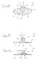
- FIGS. 1 and 2are top and exploded perspective views, respectively, of a chest brace employing patient contacting assemblies that include a pneumatic release mechanism according to the principles of the present invention
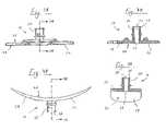
- FIG. 3Ais a side view of a chest plate patient contacting member used in the chest brace of FIGS. 1–2
- FIG. 3Bis a cross-sectional view of the chest plate patient contacting member taken along line 3 B— 3 B of FIG. 3A ;
- FIG. 4Ais a side view of a back plate patient contacting member used in the chest brace of FIGS. 1–2
- FIG. 4Bis a cross-sectional view of the back plate patient contacting member taken along line 4 B— 4 B of FIG. 4A ;
- FIGS. 5A and 5Bare perspective and cross-sectional views, respectively, of a medical electrode as a patient contacting member having a pneumatic release mechanism according to the principles of the present invention.
- FIG. 6is a cross-sectional view of a medical electrode having a pneumatic release mechanism according to a further embodiment of the present invention.
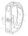
- FIGS. 1–4BA chest brace 30 having a chest plate 32 and a back plate 34 , each of which includes a pneumatic release mechanism, generally indicated at 36 , according to the principles of the present invention, is shown schematically in FIGS. 1–4B .
- the details of chest brace 30 and its operationare set forth in co-pending U.S. Pat. No. 6,533,739, the contents of which are incorporated herein by reference.
- the present inventionis directed to the pneumatic release mechanism for selectively attaching a patient contacting assembly to a patient.
- the patient contacting assemblyis chest plate 32 and back plate 34 .
- other devicescan function as the patient contacting assembly, as discussed below, for example, with reference to FIGS. 5A–6 , which illustrates a medical electrode as the patient contacting assembly.
- chest brace 30includes an anterior member 38 , a posterior member 40 , and flexible linkages 42 that couple anterior member 38 and posterior member 40 .
- Anterior member 38is coupled to the patient via chest plate 32
- posterior member 40is coupled to the patient via back plate 34 .
- a first surface 44 of chest plate 32is adhesively secured to the patient's chest
- a first surface 46 of back plate 34is adhesively secured to the patient's back.
- Chest plate 32 and back plate 34are releaseably secured to anterior member 38 and posterior member 40 , respectively.
- the chest braceprevents collapse of the patient's chest walls and maintains the shape of the thorax.
- the chest brace in the illustrated exemplary embodimentis intended to be used on infants, especially premature infants, which typically have delicate and fragile skin tissue. Therefore, it is also important that the chest and back plates be capable of being easily removed from such tissue, which a primary purpose of the pneumatic release mechanism of the present invention.
- Chest plate 32includes a relatively planar base 48 , which acts a patient contacting member in that it is surface 44 of base 48 that adheres to the patient via an adhesive applied to surface 44 , the surface of the patient, or both.
- base 48is a relative rigid member. It is to be understood, however, that the base, or portions thereof, can be made relatively flexible to make it easy for the base to contact the generally non-planar surface of the patient.
- a stem 50 attached to base 48secures the chest plate to anterior member 38 in a slot and key configuration by interlocking in a channel 51 defined in the center of the anterior member. In the illustrated exemplary embodiment, stem 50 also serves as part of the pneumatic release mechanism, as discussed in greater detail below.
- a hydrogel adhesive of the type used conventionally to secure EKG electrodes to a patientis used as an adhesive material to bond surface 44 of chest plate 32 to the surface of the patient.
- a hydrogel adhesivesuch as the hydrogel adhesive identified as RG73P and manufactured by Ludlow Technical Products of Huntington Beach, Calif., which is a water-based adhesive, is preferred because, as a hydrogel, it dissolves or has reduced adhering capability when flushed with water or a saline solution. Therefore, the adhesive can easily removed from the patient with a minimal amount of tissue damage and pulling using only water as a solvent.
- a water-based hydrogelis believed to be preferably due to its biocompatibility with human tissue, the present invention also contemplates using other types of hydrogels, such as oil-based adhesives, to secure the back plate and chest plate to the surface of the patient.
- pneumatic release mechanism 36 incorporated into chest plate 32includes a channel 52 is defined in stem 50 .
- One end 54 of channel 52is adapted to receive a liquid, preferably a solvent capable of dissolving or reducing the adhesive strength of the hydrogel, so that the liquid can be inserted into the channel.
- a second end 56 of channel 52is provided at surface 44 so that the liquid injected into the channel can be delivered between surface 44 and the surface of the patient.
- the insertion of such a liquid between surface 44 and the surface of the patientalso provides a pneumatic release mechanism tending to urge surface 44 and the surface of the patient apart. That is, a liquid injected between the patient and surface 44 tends to dislodge or lift surface 44 from the patient in a pneumatic fashion.
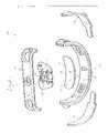
- Back plate 34is similar to chest plate 32 except that back plate 34 includes a base 58 that is curved to match the general curvature of the back of the patient, unlike base 48 .
- a stem 60 attached to base 58secures the back plate to posterior member 40 in a slot and key configuration by interlocking in a channel 62 defined in the center of the posterior member.
- stem 60also serves as part of the pneumatic release mechanism in that the stem includes a channel 64 .
- Surface 46 of base 58adheres to the back of the patient, preferably using the above-described hydrogel adhesive.
- stem 60 of back plate 38includes a channel 64 so that a liquid, preferably a solvent, can be inserted into a first end 66 of the channel and delivered to an opening 68 in a second end of the channel so that the liquid is discharged between surface 46 and the surface of the patient.
- a liquidpreferably a solvent
- the insertion of such a liquid between surface 46 and the surface of the patientassists in dissolving or reducing the strength of the adhesive securing surface 46 to the patient and provides a pneumatic release mechanism tending to urge surface 46 and the surface of the patient apart.
- the channel that carries the release fluid to surface of the patientis defined in a stem attached to the base. It is to be understood, however, that channel need not be provided in the stem. Rather, a channel can be provided at any one of a variety of locations on the base, so long as the channel communicates the release fluid to a location between surface 44 or 46 . Furthermore, if provided in the stem, the channel need not run generally parallel to the stem. Also, other openings can be provided along the stem into which the release fluid can be injected. It is to be further understood that a plurality of channels, with or without a stem, can be provided at other locations on the base.
- FIGS. 5A–5Billustrate a patient contacting assembly 70 in which a medical electrode 72 is the patient contacting member that operates in conjunction with a pneumatic release mechanism, generally indicated at 74 , according to the principles of the present invention.
- Patient contacting assembly 70includes a substrate 76 to which an electrode 78 is attached. It is to be understood that electrode 78 can be attached to the substrate, imbedded in the substrate, or secured at other locations on the substrate and in any manner known to those skilled in the art. In this illustrated embodiment, electrode 78 is attached to a surface 79 of the substrate. A stem 80 is provided on an opposing surface. As in the previous embodiments, a channel 82 is defined in stem 80 enabling a release liquid injected in a first end 84 to be dispensed from a second end 86 of the channel and disposed between surface 79 and a surface of a patient to which the substrate is attached (not shown).
- stem 80is integral with substrate 72 .
- each element of the patient contacting membercan be formed separately, out of different materials if desired, and affixed to one another during the manufacturing process in any conventional manner.
- Stem 80 in the embodiment illustrated in FIGS. 5A–5Bserves dual functions.
- stem 80provides a channel into which the release fluid is injected using a syringe, for example.
- Stem 80can also serve as a contact terminal for an electrical connection between an external lead wire and electrode 78 .
- the illustrated embodimentfor example, provides a contact terminal 88 at first end 84 so that an electrical lead (not shown) can be operatively connected to electrode 78 by means of selective attachment to contact 88 .
- an electrical connectionis provided between contact 88 and electrode 78 .
- This electrical connectioncan be provided through channel 82 .
- stem 80can be eliminated, channel 82 provided only within substrate 72 , and an electrical contact can be provided using any conventional technique.
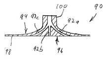
- FIG. 6is a cross-sectional view of a patient contacting assembly 90 in which the patient contact member is also a medical electrode.
- the pneumatic release mechanismincludes multiple channels 92 a , 92 b , 92 c defined in the substrate 98 from a first surface 94 to a second surface 96 thereof.
- the use of multiple channelshelps ensure that the release fluid is more completely distributed over the area of second surface 96 .
- channels 92 a – 92 cbranch off of a main channel in stem 100 . It is to be understood, however, that the channels can be provided at other locations throughout the substrate and need not be provided in the stem. In addition, each channel can have multiple branches.
- the pneumatic release mechanism of the present inventioncan be used, for example, with a medical mask (nasal, oral, or both), such as the mask taught by U.S. Pat. No. 3,357,426 to Cohen.
- the pneumatic release mechanismcan also be used with a medical adhesive strip or tape making it easier to remove same.
- the pneumatic release mechanismcan be used with a traction or brace device in which a portion of the device is adhered to the surface of a patient, such as the chest brace taught by U.S. Pat. Nos. 5,820,572 and 6,059,742 both to Palmer.
- Other applications for the pneumatic release mechanisminclude a dental appliance, a prostheses, or any situation where a material, element or other components is removeably affixed to the tissue of a patient.
- the present inventionalso contemplates that the pneumatic release mechanism of the present invention has non-medical applications.
- an appliancefor example, in the make-up, special effects, or cosmetic industry, there is often a need to adhere an appliance to an actor or user.
- a biocompatible adhesiveis typically used to secure the appliance to the actor.
- the present inventioncontemplates providing a pneumatic release mechanism on the appliance so that it can be more easily removed. It is to be understood that the above list of potential applications for the pneumatic release mechanism is intended to be exemplary of the situations where such a release mechanism may have merit. It is not intended to represent a complete or exclusive catalog of all such applications. On the contrary, the present invention contemplates that the pneumatic release mechanism of the present invention is applicable to in any situation where an element is to be releaseably secured to a person or animal.
Landscapes
- Life Sciences & Earth Sciences (AREA)
- Health & Medical Sciences (AREA)
- Medical Informatics (AREA)
- Biophysics (AREA)
- Pathology (AREA)
- Engineering & Computer Science (AREA)
- Biomedical Technology (AREA)
- Heart & Thoracic Surgery (AREA)
- Physics & Mathematics (AREA)
- Molecular Biology (AREA)
- Surgery (AREA)
- Animal Behavior & Ethology (AREA)
- General Health & Medical Sciences (AREA)
- Public Health (AREA)
- Veterinary Medicine (AREA)
- Electrotherapy Devices (AREA)
Abstract
Description
Claims (13)
Priority Applications (1)
| Application Number | Priority Date | Filing Date | Title |
|---|---|---|---|
| US09/924,869US6952605B1 (en) | 2000-08-10 | 2001-08-08 | Pneumatic release mechanism for a patient contacting article |
Applications Claiming Priority (2)
| Application Number | Priority Date | Filing Date | Title |
|---|---|---|---|
| US22424300P | 2000-08-10 | 2000-08-10 | |
| US09/924,869US6952605B1 (en) | 2000-08-10 | 2001-08-08 | Pneumatic release mechanism for a patient contacting article |
Publications (1)
| Publication Number | Publication Date |
|---|---|
| US6952605B1true US6952605B1 (en) | 2005-10-04 |
Family
ID=35005195
Family Applications (1)
| Application Number | Title | Priority Date | Filing Date |
|---|---|---|---|
| US09/924,869Expired - Fee RelatedUS6952605B1 (en) | 2000-08-10 | 2001-08-08 | Pneumatic release mechanism for a patient contacting article |
Country Status (1)
| Country | Link |
|---|---|
| US (1) | US6952605B1 (en) |
Cited By (16)
| Publication number | Priority date | Publication date | Assignee | Title |
|---|---|---|---|---|
| EP2196141A1 (en)* | 2008-12-08 | 2010-06-16 | Charité Universitätsmedizin Berlin | Measurement device for non-invasive long-term measurement of blood pressure |
| US20130172724A1 (en)* | 2011-09-09 | 2013-07-04 | University Of Maryland | Quick-release self-contained medical electrode |
| US8548558B2 (en) | 2008-03-06 | 2013-10-01 | Covidien Lp | Electrode capable of attachment to a garment, system, and methods of manufacturing |
| US8868216B2 (en) | 2008-11-21 | 2014-10-21 | Covidien Lp | Electrode garment |
| EP2854743A4 (en)* | 2012-06-01 | 2016-02-17 | Zoll Medical Corp | Chest compression belt with belt position monitoring system |
| US20170231566A1 (en)* | 2014-08-15 | 2017-08-17 | Nonin Medical, Inc. | Tissue interface |
| US9820670B2 (en)* | 2016-03-29 | 2017-11-21 | CeriBell, Inc. | Methods and apparatus for electrode placement and tracking |
| US10433756B1 (en) | 2018-05-31 | 2019-10-08 | CeriBell, Inc. | Adjustable geometry wearable electrodes |
| US10905837B2 (en) | 2015-04-02 | 2021-02-02 | Hill-Rom Services Pte. Ltd. | Respiratory therapy cycle control and feedback |
| US11179286B2 (en) | 2016-10-21 | 2021-11-23 | Zoll Medical Corporation | Adaptive body positioning |
| US11219413B2 (en)* | 2014-08-26 | 2022-01-11 | Dexcom, Inc. | Systems and methods for securing a continuous analyte sensor to a host |
| US11241182B1 (en) | 2021-04-07 | 2022-02-08 | Forest Devices, Inc. | Gel distribution apparatus and method |
| US11266476B1 (en) | 2021-04-07 | 2022-03-08 | Forest Devices, Inc. | Headgear storage device and method of distribution |
| USD970019S1 (en) | 2021-04-07 | 2022-11-15 | Forest Devices, Inc. | Gel distribution module |
| USD1018861S1 (en) | 2021-04-07 | 2024-03-19 | Forest Devices, Inc. | Headgear |
| US12233020B2 (en) | 2016-10-21 | 2025-02-25 | Zoll Medical Corporation | System and methods for adaptive body positioning during chest compressions |
Citations (25)
| Publication number | Priority date | Publication date | Assignee | Title |
|---|---|---|---|---|
| US2882904A (en)* | 1954-04-07 | 1959-04-21 | Burdick Corp | Flexible induction electrode |
| US3295515A (en)* | 1963-11-05 | 1967-01-03 | Beckman Instruments Inc | Electrode assembly |
| US3357426A (en) | 1965-01-14 | 1967-12-12 | Univ California | Adherent face mask having a quick disconnect fitting and disposable components |
| US3420223A (en)* | 1964-12-31 | 1969-01-07 | Nasa | Electrode for biological recording |
| US3599629A (en)* | 1968-08-28 | 1971-08-17 | Lexington Instr | Oxidized surface biopotential skin electrode |
| US3602216A (en)* | 1969-09-16 | 1971-08-31 | United Aircraft Corp | Paste dispensing body electrode |
| US3610229A (en)* | 1969-03-07 | 1971-10-05 | Ilias Zenkich | Electrocardiograph electrodes with conductive jelly supply means |
| US3623479A (en)* | 1969-11-21 | 1971-11-30 | American Optical Corp | Ecg electrode with partition |
| US3713435A (en)* | 1972-06-05 | 1973-01-30 | Ndm Corp | Pickup electrode with rigid electrolyte cup |
| US3862633A (en)* | 1974-05-06 | 1975-01-28 | Kenneth C Allison | Electrode |
| US3973557A (en)* | 1975-04-21 | 1976-08-10 | Allison Kenneth C | Electrode |
| US4182346A (en)* | 1977-06-02 | 1980-01-08 | Biomedical International Company | Electrode |
| US4215696A (en)* | 1978-03-20 | 1980-08-05 | Graphic Controls Corporation | Biomedical electrode with pressurized skin contact |
| US4267840A (en)* | 1979-01-08 | 1981-05-19 | Johnson & Johnson | Electrosurgical grounding pad |
| US4660562A (en)* | 1985-03-07 | 1987-04-28 | House Sr Hugh A | Multi-event biomedical electrode assembly |
| US4700710A (en)* | 1985-03-12 | 1987-10-20 | Murray Electronics Associates Limited Partnership | Apertured adhesively applied body electrode apparatus and method |
| US4947865A (en)* | 1987-11-09 | 1990-08-14 | The Hon Group | Sensor support plate with detachable ring |
| US5037380A (en)* | 1989-05-09 | 1991-08-06 | Iomed, Inc. | Iontophoretic electrode with solution containment system |
| US5124076A (en)* | 1990-01-19 | 1992-06-23 | Contour Electrodes, Inc. | Rapid, curing, electrically conductive adhesive |
| US5279544A (en)* | 1990-12-13 | 1994-01-18 | Sil Medics Ltd. | Transdermal or interdermal drug delivery devices |
| US5573503A (en)* | 1984-10-29 | 1996-11-12 | Alza Corporation | Iontophoretic drug delivery |
| US5820572A (en) | 1995-11-21 | 1998-10-13 | The Penn State Research Foundation | Negative pressure chest brace |
| US5848966A (en)* | 1997-03-04 | 1998-12-15 | Graphic Controls Corporation | Medical device easily removed from skin and a method of removal therefrom |
| US5868136A (en) | 1996-02-20 | 1999-02-09 | Axelgaard Manufacturing Co. Ltd. | Medical electrode |
| US5983131A (en)* | 1995-08-11 | 1999-11-09 | Massachusetts Institute Of Technology | Apparatus and method for electroporation of tissue |
- 2001
- 2001-08-08USUS09/924,869patent/US6952605B1/ennot_activeExpired - Fee Related
Patent Citations (26)
| Publication number | Priority date | Publication date | Assignee | Title |
|---|---|---|---|---|
| US2882904A (en)* | 1954-04-07 | 1959-04-21 | Burdick Corp | Flexible induction electrode |
| US3295515A (en)* | 1963-11-05 | 1967-01-03 | Beckman Instruments Inc | Electrode assembly |
| US3420223A (en)* | 1964-12-31 | 1969-01-07 | Nasa | Electrode for biological recording |
| US3357426A (en) | 1965-01-14 | 1967-12-12 | Univ California | Adherent face mask having a quick disconnect fitting and disposable components |
| US3599629A (en)* | 1968-08-28 | 1971-08-17 | Lexington Instr | Oxidized surface biopotential skin electrode |
| US3610229A (en)* | 1969-03-07 | 1971-10-05 | Ilias Zenkich | Electrocardiograph electrodes with conductive jelly supply means |
| US3602216A (en)* | 1969-09-16 | 1971-08-31 | United Aircraft Corp | Paste dispensing body electrode |
| US3623479A (en)* | 1969-11-21 | 1971-11-30 | American Optical Corp | Ecg electrode with partition |
| US3713435A (en)* | 1972-06-05 | 1973-01-30 | Ndm Corp | Pickup electrode with rigid electrolyte cup |
| US3862633A (en)* | 1974-05-06 | 1975-01-28 | Kenneth C Allison | Electrode |
| US3973557A (en)* | 1975-04-21 | 1976-08-10 | Allison Kenneth C | Electrode |
| US4182346A (en)* | 1977-06-02 | 1980-01-08 | Biomedical International Company | Electrode |
| US4215696A (en)* | 1978-03-20 | 1980-08-05 | Graphic Controls Corporation | Biomedical electrode with pressurized skin contact |
| US4267840A (en)* | 1979-01-08 | 1981-05-19 | Johnson & Johnson | Electrosurgical grounding pad |
| US5573503A (en)* | 1984-10-29 | 1996-11-12 | Alza Corporation | Iontophoretic drug delivery |
| US4660562A (en)* | 1985-03-07 | 1987-04-28 | House Sr Hugh A | Multi-event biomedical electrode assembly |
| US4700710A (en)* | 1985-03-12 | 1987-10-20 | Murray Electronics Associates Limited Partnership | Apertured adhesively applied body electrode apparatus and method |
| US4947865A (en)* | 1987-11-09 | 1990-08-14 | The Hon Group | Sensor support plate with detachable ring |
| US5037380A (en)* | 1989-05-09 | 1991-08-06 | Iomed, Inc. | Iontophoretic electrode with solution containment system |
| US5124076A (en)* | 1990-01-19 | 1992-06-23 | Contour Electrodes, Inc. | Rapid, curing, electrically conductive adhesive |
| US5279544A (en)* | 1990-12-13 | 1994-01-18 | Sil Medics Ltd. | Transdermal or interdermal drug delivery devices |
| US5983131A (en)* | 1995-08-11 | 1999-11-09 | Massachusetts Institute Of Technology | Apparatus and method for electroporation of tissue |
| US5820572A (en) | 1995-11-21 | 1998-10-13 | The Penn State Research Foundation | Negative pressure chest brace |
| US6059742A (en) | 1995-11-21 | 2000-05-09 | The Penn State Research Foundation | Negative pressure chest brace |
| US5868136A (en) | 1996-02-20 | 1999-02-09 | Axelgaard Manufacturing Co. Ltd. | Medical electrode |
| US5848966A (en)* | 1997-03-04 | 1998-12-15 | Graphic Controls Corporation | Medical device easily removed from skin and a method of removal therefrom |
Cited By (28)
| Publication number | Priority date | Publication date | Assignee | Title |
|---|---|---|---|---|
| US8548558B2 (en) | 2008-03-06 | 2013-10-01 | Covidien Lp | Electrode capable of attachment to a garment, system, and methods of manufacturing |
| US8868216B2 (en) | 2008-11-21 | 2014-10-21 | Covidien Lp | Electrode garment |
| EP2196141A1 (en)* | 2008-12-08 | 2010-06-16 | Charité Universitätsmedizin Berlin | Measurement device for non-invasive long-term measurement of blood pressure |
| US20130172724A1 (en)* | 2011-09-09 | 2013-07-04 | University Of Maryland | Quick-release self-contained medical electrode |
| US8897853B2 (en)* | 2011-09-09 | 2014-11-25 | University Of Maryland | Quick-release self-contained medical electrode |
| US9925114B2 (en) | 2012-06-01 | 2018-03-27 | Zoll Medical Corporation | Chest compression belt with belt position monitoring system |
| EP2854743A4 (en)* | 2012-06-01 | 2016-02-17 | Zoll Medical Corp | Chest compression belt with belt position monitoring system |
| US10918566B2 (en) | 2012-06-01 | 2021-02-16 | Zoll Medical Corporation | Chest compression belt with belt position monitoring system |
| US20170231566A1 (en)* | 2014-08-15 | 2017-08-17 | Nonin Medical, Inc. | Tissue interface |
| US12396682B2 (en) | 2014-08-26 | 2025-08-26 | Dexcom, Inc. | Systems and methods for securing a continuous analyte sensor to a host |
| US11219413B2 (en)* | 2014-08-26 | 2022-01-11 | Dexcom, Inc. | Systems and methods for securing a continuous analyte sensor to a host |
| US11992611B2 (en) | 2015-04-02 | 2024-05-28 | Hill-Rom Services Pte. Ltd. | Respiratory therapy apparatus control |
| US10905837B2 (en) | 2015-04-02 | 2021-02-02 | Hill-Rom Services Pte. Ltd. | Respiratory therapy cycle control and feedback |
| US10905836B2 (en) | 2015-04-02 | 2021-02-02 | Hill-Rom Services Pte. Ltd. | Manifold for respiratory device |
| US9820670B2 (en)* | 2016-03-29 | 2017-11-21 | CeriBell, Inc. | Methods and apparatus for electrode placement and tracking |
| US10888240B2 (en) | 2016-03-29 | 2021-01-12 | CeriBell, Inc. | Methods and apparatus for electrode placement and tracking |
| US12336826B2 (en) | 2016-03-29 | 2025-06-24 | CeriBell, Inc. | Methods and apparatus for electrode placement and tracking |
| US12324670B2 (en) | 2016-03-29 | 2025-06-10 | CeriBell, Inc. | Methods and apparatus for electrode placement and tracking |
| US12150769B2 (en) | 2016-03-29 | 2024-11-26 | CeriBell, Inc. | Methods and apparatus for electrode placement and tracking |
| US12285383B2 (en) | 2016-10-21 | 2025-04-29 | Zoll Medical Corporation | System and methods for adaptive body positioning during chest compressions |
| US12233020B2 (en) | 2016-10-21 | 2025-02-25 | Zoll Medical Corporation | System and methods for adaptive body positioning during chest compressions |
| US11179286B2 (en) | 2016-10-21 | 2021-11-23 | Zoll Medical Corporation | Adaptive body positioning |
| US11357434B2 (en) | 2018-05-31 | 2022-06-14 | CeriBell, Inc. | Adjustable geometry wearable electrodes |
| US10433756B1 (en) | 2018-05-31 | 2019-10-08 | CeriBell, Inc. | Adjustable geometry wearable electrodes |
| USD1018861S1 (en) | 2021-04-07 | 2024-03-19 | Forest Devices, Inc. | Headgear |
| USD970019S1 (en) | 2021-04-07 | 2022-11-15 | Forest Devices, Inc. | Gel distribution module |
| US11266476B1 (en) | 2021-04-07 | 2022-03-08 | Forest Devices, Inc. | Headgear storage device and method of distribution |
| US11241182B1 (en) | 2021-04-07 | 2022-02-08 | Forest Devices, Inc. | Gel distribution apparatus and method |
Similar Documents
| Publication | Publication Date | Title |
|---|---|---|
| US6952605B1 (en) | Pneumatic release mechanism for a patient contacting article | |
| CA2145642C (en) | Electrotransport system having flexible means | |
| AU750912B2 (en) | Methods and apparatus for ocular iontophoresis | |
| US8696619B2 (en) | Drug delivery devices | |
| JP5809060B2 (en) | Electrode garment | |
| TW539564B (en) | Methods and apparatus for ocular iontophoresis | |
| US6778862B2 (en) | Electrical stimulation compress method | |
| US6400975B1 (en) | Apparatus and method for consistent patient-specific electrode positioning for EKG testing and delivery of electrical energy to the heart | |
| DK1923081T3 (en) | Fastening device on a body worn infusion device | |
| US5848966A (en) | Medical device easily removed from skin and a method of removal therefrom | |
| CA2332834A1 (en) | Adhesive system for attaching medical devices to a surface | |
| EP2277585A3 (en) | Iontophoretic drug delivery electrodes | |
| US20030087216A1 (en) | Rubber dam clamps retained by adhesion and improved frictional forces | |
| US6019103A (en) | Disposable sanitary eye protector | |
| US6788979B1 (en) | Electrical stimulation compress kit | |
| WO1994027491A2 (en) | Intraoral-procedures electrode | |
| HUP0200875A2 (en) | Ostomy siting device | |
| US6728573B1 (en) | Ocular iontophoretic apparatus handle | |
| TW526071B (en) | High current density iontophoretic device and method of use thereof | |
| CN102316793B (en) | Probe electrode pad and probe electrode pad storage box | |
| EP0390761B1 (en) | Implantable device for the supply of a liquid to the oral cavity | |
| CN219481308U (en) | An electrode wire fixing paste | |
| CN211705621U (en) | Electric pulse simulation acupuncture treatment device | |
| GB2596039A (en) | A stoma bag | |
| ITMI20001459A1 (en) | APPARATUS AND APPLICATOR PACK FOR TRANSCUTANEOUS ADMINISTRATION OF SUBSTANCES. |
Legal Events
| Date | Code | Title | Description |
|---|---|---|---|
| AS | Assignment | Owner name:RIC INVESTMENTS, INC.,DELAWARE Free format text:DIVIDEND FROM SUBSIDIARY TO PARENT;ASSIGNOR:RESPIRONICS, INC.;REEL/FRAME:016741/0570 Effective date:20020627 Owner name:RIC INVESTMENTS, INC., DELAWARE Free format text:DIVIDEND FROM SUBSIDIARY TO PARENT;ASSIGNOR:RESPIRONICS, INC.;REEL/FRAME:016741/0570 Effective date:20020627 | |
| AS | Assignment | Owner name:RIC INVESTMENTS, LLC.,DELAWARE Free format text:CHANGE OF NAME;ASSIGNOR:RIC INVESTMENTS, INC.;REEL/FRAME:016747/0177 Effective date:20040317 Owner name:RIC INVESTMENTS, LLC., DELAWARE Free format text:CHANGE OF NAME;ASSIGNOR:RIC INVESTMENTS, INC.;REEL/FRAME:016747/0177 Effective date:20040317 | |
| FPAY | Fee payment | Year of fee payment:4 | |
| SULP | Surcharge for late payment | ||
| REMI | Maintenance fee reminder mailed | ||
| LAPS | Lapse for failure to pay maintenance fees | ||
| STCH | Information on status: patent discontinuation | Free format text:PATENT EXPIRED DUE TO NONPAYMENT OF MAINTENANCE FEES UNDER 37 CFR 1.362 | |
| FP | Lapsed due to failure to pay maintenance fee | Effective date:20131004 |