US6952165B2 - Concealed wireless sensor with external antenna - Google Patents
Concealed wireless sensor with external antennaDownload PDFInfo
- Publication number
- US6952165B2 US6952165B2US10/742,503US74250303AUS6952165B2US 6952165 B2US6952165 B2US 6952165B2US 74250303 AUS74250303 AUS 74250303AUS 6952165 B2US6952165 B2US 6952165B2
- Authority
- US
- United States
- Prior art keywords
- housing
- radio frequency
- antenna
- sensor circuit
- security sensor
- Prior art date
- Legal status (The legal status is an assumption and is not a legal conclusion. Google has not performed a legal analysis and makes no representation as to the accuracy of the status listed.)
- Expired - Lifetime, expires
Links
Images


Classifications
- G—PHYSICS
- G08—SIGNALLING
- G08B—SIGNALLING OR CALLING SYSTEMS; ORDER TELEGRAPHS; ALARM SYSTEMS
- G08B13/00—Burglar, theft or intruder alarms
- G08B13/02—Mechanical actuation
- G08B13/08—Mechanical actuation by opening, e.g. of door, of window, of drawer, of shutter, of curtain, of blind
Definitions
- the present inventionrelates to security systems, and in particular to a wireless security device that may be embedded within a recess in a door or window with an externally located antenna for superior signal transmission performance.
- the present inventionis a wireless security device, such as a door or window motion sensor, that can be mounted almost entirely within a recess of a door, window or frame, with only the antenna mounted on the surface of the door or window jamb.
- the wireless security devicehas a housing suitable for being embedded within a structure such as a door, window or frame.
- a security sensor circuitadapted to generate an alarm signal when activated
- a radio frequency (RF) transmitterconnected to the security sensor circuit for transmitting an RF signal when the alarm signal is generated
- a power sourcesuch as a battery, piezoelectric element, solar cell or fuel cell
- a substantially flat surface mountable stripis located in proximity to the housing and is suitable for being mounted outside (i.e. along the surface of the structure).
- the surface mountable striphas an antenna that is coupled to the RF transmitter for emitting electromagnetic energy corresponding to the RF signal from the transmitter.
- the surface mountable stripis a plastic strip and the antenna is injection molded into the strip and electrically connected to the RF transmitter within the recessed housing.
- the shape of the housingis preferably cylindrical, and the surface mountable strip and housing form an integral assembly with the cylindrical housing being embedded in a hole bored into the mounting structure (e.g. the window) and the surface mountable strip forming a top circular portion that overlaps the hole and lays flat against the surface of the door or window jamb.
- the wireless security deviceis almost entirely recessed, with the antenna laying flat against the mounting surface.
- Thisprovides for easy mounting of the security device within the window or like structure, and also provides the desired advantage of the antenna being externally mounted for better transmission and/or reception, due to being externally mounted and substantially isolated from the circuitry and power source within the housing.
- the present inventionprovides a more predictable antenna pattern than heretofore available under the prior art.
- the surface mountable stripis physically discrete from the housing, and the antenna is printed onto the strip with conductive ink.
- a transfer coilis used to transduce the transmitted signal from the RF transmitter to the antenna (as an alternative to the direct wired connection in the first embodiment). This allows greater flexibility in sizing and placement of the antenna strip with respect to the embedded housing.
- the surface mountable stripis thin enough to be located on a portion of a window or door that slides or closes with respect to a frame (or on the frame itself) without interfering with the operation of the door or window.
- the stripmay be paintable and thus blend in with the decor of the premises.
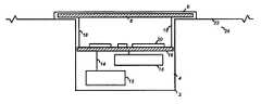
- FIG. 1is a side view cross-section of the preferred embodiment of the present invention
- FIG. 2is an illustration of an alternative embodiment of the present invention
- FIG. 3is an illustration of the present invention installed in a door
- FIG. 4is an illustration of an alternative embodiment of the present invention installed in a door.
- a wireless security device 2which has a cylindrical housing 4 and a surface mountable strip in the form of a round, substantially flat top portion 6 .
- the housingis preferably cylindrical so that an installer can bore a hole within a structure 24 such as a window or door, and then easily insert the cylindrical housing into the hole.
- the housingmay also be in other shapes, such as a rectangular prism, as desired by the designer.
- By making the top portion 6 longer in length than the housingthe top portion will rest easily against the surface 22 of the structure 24 .
- the dimensions of the housing 4 and the holemay be configured so that the housing 4 will press fit snugly within the hole, or an adhesive may be used to provide for secure mounting.
- the top portion 6is relatively thin, preferably on the order of approximately 0.050′′ thick, so that it lays substantially flat against the surface 22 . This unobtrusive design allows placement of the wireless security device in a window or door without interfering with the movement of the window or door within the associated frame.
- the power source 12such as a battery
- PCBprinted circuit board
- sensor device 16which may be mounted to the PCB or which may be a discrete component within the housing 4 .
- the PCB 10has mounted thereon the appropriate electronic circuitry 20 as required by the wireless security device as described herein.
- a typical devicewill include a radio frequency (RF) transmitter and control circuitry for detecting a change of state of the sensor device 16 and generating an alarm signal.
- the alarm signalis transmitted by the RF transmitter, via an antenna 8 as described below, to an RF receiver that is part of a security system installed in the premises, as well known in the art.
- the sensor device 16may be any type of sensor that will indicate a state change when moved, such as (but not limited to) a magnetic field sensor (to sense the magnetic field of the Earth or of an externally located magnet), a gravitational field sensor, or a tilt switch.
- a magnetic field sensorto sense the magnetic field of the Earth or of an externally located magnet
- gravitational field sensorto sense the gravitational field sensor
- tilt switcha tilt switch.
- a two-piece sensor devicemay be used, although this would provide for a more complicated installation.
- a magnetic reed switchmay be used, where the housing encloses the reed switch and a magnetic actuator is located externally, typically on the opposing frame, jamb or surface of the window or door secured by the device.
- FIG. 3illustrates the mounting of the device 2 in a door 24 .
- the housing 4is seen embedded within the door 24 , and the top portion 6 , which is round, rests against the top 22 of the door 24 with a profile low enough to enable the door to easily fit within the door jamb (not shown) when it is closed.
- the antenna 8may transmit RF signals to the control panel of the associated alarm system via an RF receiver as well known in the art of security systems.
- FIG. 4illustrates the same device with a rectangular shaped top portion 6 a and antenna 8 , which may be used if desired by the device designer. Virtually any shape may be used for the top portion as long as it fits on top of the door without interfering with its operation.
- an alarm signalis generated by the control circuitry as well known in the art and provided to the RF transmitter for transmission to the control panel of the security system.
- An RF alarm signalis generated and provided to the antenna 8 , which is embedded within the top portion 6 , via conductors 18 (e.g. wires).
- the antenna 8is configured to provide optimal signal transmission for a given application.
- the antennais an 8.56′′ wire length in a diamond configuration which is optimal for transmitting the RF signal (at frequencies between 345 MHz to 868 MHz).
- the power source and PCBare preferably separated from the antenna by a distance of approximately 1 ⁇ 4′′ to 3 ⁇ 8′′. This isolation provides superior signal transmission, since the power source and circuitry on the PCB will interfere with the signal transmission much less than if the antenna were included within the housing. Thus, the present invention provides better signal transmission performance with an embedded device having a low profile external antenna.
- the top portion 6preferably overlaps the housing 4 to provide for an easier installation. That is, the length of the opening into which the housing 4 is placed need not be made to the exact length of the housing since the top portion 6 will rest against the top of the door when inserted into the opening, even if the opening is longer than the length of the housing 4 .
- the top portion 6may be made to not overlap the housing if the design of the antenna 8 permits a smaller profile.
- the antenna 8is made from copper wire.
- the antennais integrated into the top portion 6 of the housing by an injection molding process known in the art.
- the device 30has an antenna 32 that is not wired directly to the RF transmitter, but instead is coupled electromagnetically by means of an RF air core transformer 34 .
- the RF air core transformer 34is comprised of conductive ink 36 that forms one loop of the transformer 34 and an injection molded antenna 38 in the housing 40 that forms the second part of the transformer 34 .
- the antenna 32is formed of conductive ink on a clear polycarbonate strip 42 .
- the antenna strip 42may be made from various shapes and sizes, depending on the needs of the installer.
- the antennamay be arranged in various manners so as to provide optimal signal transference between the RF transmitter and the security system RF receiver.
- An adhesiveis placed on the bottom side of the strip 42 for easy mounting to the desired surface.
Landscapes
- Physics & Mathematics (AREA)
- General Physics & Mathematics (AREA)
- Alarm Systems (AREA)
Abstract
Description
Claims (46)
Priority Applications (1)
| Application Number | Priority Date | Filing Date | Title |
|---|---|---|---|
| US10/742,503US6952165B2 (en) | 2003-12-19 | 2003-12-19 | Concealed wireless sensor with external antenna |
Applications Claiming Priority (1)
| Application Number | Priority Date | Filing Date | Title |
|---|---|---|---|
| US10/742,503US6952165B2 (en) | 2003-12-19 | 2003-12-19 | Concealed wireless sensor with external antenna |
Publications (2)
| Publication Number | Publication Date |
|---|---|
| US20050134471A1 US20050134471A1 (en) | 2005-06-23 |
| US6952165B2true US6952165B2 (en) | 2005-10-04 |
Family
ID=34678468
Family Applications (1)
| Application Number | Title | Priority Date | Filing Date |
|---|---|---|---|
| US10/742,503Expired - LifetimeUS6952165B2 (en) | 2003-12-19 | 2003-12-19 | Concealed wireless sensor with external antenna |
Country Status (1)
| Country | Link |
|---|---|
| US (1) | US6952165B2 (en) |
Cited By (18)
| Publication number | Priority date | Publication date | Assignee | Title |
|---|---|---|---|---|
| US20050179545A1 (en)* | 2003-11-13 | 2005-08-18 | All Set Marine Security Ab | Method and system for monitoring containers to maintain the security thereof |
| US20100052576A1 (en)* | 2008-09-03 | 2010-03-04 | Steiner James P | Radio-frequency lighting control system with occupancy sensing |
| US20100052894A1 (en)* | 2008-09-03 | 2010-03-04 | Steiner James P | Battery-powered occupancy sensor |
| US20100207759A1 (en)* | 2009-02-13 | 2010-08-19 | Lutron Electronics Co., Inc. | Method and Apparatus for Configuring a Wireless Sensor |
| US20110006893A1 (en)* | 2007-08-05 | 2011-01-13 | John Gerard Finch | Notification system utilizing self-energizing switches |
| US7948372B1 (en)* | 2003-10-03 | 2011-05-24 | Herbold Daniel J | Method and apparatus for concealing sensors in urban and industrial environments |
| US8228184B2 (en) | 2008-09-03 | 2012-07-24 | Lutron Electronics Co., Inc. | Battery-powered occupancy sensor |
| US8337039B1 (en) | 2008-08-28 | 2012-12-25 | Larkin Kevin B | Window frame with integrated solar electric cell and illumination |
| US20140001336A1 (en)* | 2012-06-27 | 2014-01-02 | Leviton Manufacturing Co., Inc. | Solar powered radio frequency transmitter |
| US8665084B2 (en) | 2011-07-29 | 2014-03-04 | Adt Us Holdings, Inc. | Security system and method |
| US20150029023A1 (en)* | 2013-07-26 | 2015-01-29 | Cinch Systems, Inc. | Cover mounted circuit board and antenna |
| US9148937B2 (en) | 2008-09-03 | 2015-09-29 | Lutron Electronics Co., Inc. | Radio-frequency lighting control system with occupancy sensing |
| US9277629B2 (en) | 2008-09-03 | 2016-03-01 | Lutron Electronics Co., Inc. | Radio-frequency lighting control system with occupancy sensing |
| US9273840B1 (en) | 2013-03-13 | 2016-03-01 | Marlin Braun | Integrated illumination system |
| US10080274B2 (en) | 2016-09-09 | 2018-09-18 | Abl Ip Holding Llc | Control modules having integral antenna components for luminaires and wireless intelligent lighting systems containing the same |
| USRE47511E1 (en) | 2008-09-03 | 2019-07-09 | Lutron Technology Company Llc | Battery-powered occupancy sensor |
| US10789797B2 (en) | 2017-09-22 | 2020-09-29 | Schlage Lock Company Llc | Peripheral controller in an access control system |
| EP3937144A3 (en)* | 2013-09-19 | 2022-06-08 | Sensative AB | Elongated wireless sensor assembly |
Families Citing this family (7)
| Publication number | Priority date | Publication date | Assignee | Title |
|---|---|---|---|---|
| US8333433B2 (en)* | 2010-02-10 | 2012-12-18 | Friedman Mark J | Locking harness apparatus and method |
| DE102010053226B4 (en)* | 2010-12-03 | 2025-04-17 | Stabilus Gmbh | drive device |
| DE102010053225A1 (en)* | 2010-12-03 | 2012-06-06 | Stabilus Gmbh | driving means |
| US10720033B2 (en)* | 2013-09-19 | 2020-07-21 | Sensative Ab | Elongated wireless sensor assembly |
| US10282565B2 (en)* | 2017-07-23 | 2019-05-07 | Albert C Abnett | Computer security environment |
| US11514770B2 (en)* | 2019-11-13 | 2022-11-29 | Carrier Corporation | Alarm with enhanced radio performance by isolation of radio from alarm components |
| GR1009881B (en)* | 2020-02-11 | 2020-12-02 | People Technology Solutions, Ltd. | Door for smart shipping containers |
Citations (10)
| Publication number | Priority date | Publication date | Assignee | Title |
|---|---|---|---|---|
| US3725887A (en)* | 1968-06-10 | 1973-04-03 | Sneider Electronic Sys Inc | Radio transmitting alarm system |
| US5164705A (en) | 1990-02-15 | 1992-11-17 | Larmco Security, Inc. | Anti-intrusion window |
| US5512874A (en)* | 1994-05-04 | 1996-04-30 | T. B. Poston | Security device |
| US5970393A (en) | 1997-02-25 | 1999-10-19 | Polytechnic University | Integrated micro-strip antenna apparatus and a system utilizing the same for wireless communications for sensing and actuation purposes |
| US6157344A (en) | 1999-02-05 | 2000-12-05 | Xertex Technologies, Inc. | Flat panel antenna |
| US6310549B1 (en)* | 2000-08-29 | 2001-10-30 | Digitech International | Wireless security system |
| US6492960B2 (en) | 1999-05-03 | 2002-12-10 | Centurion Wireless Technologies, Inc. | Plastic or die-cast antennas for a wireless communications device |
| US6684671B2 (en)* | 2000-11-02 | 2004-02-03 | Best Lock Corporation | Vending machine lock |
| US6737969B2 (en)* | 2001-11-27 | 2004-05-18 | Ion Digital Llp | Wireless security sensor systems for windows and doors |
| US6753757B1 (en)* | 1998-02-16 | 2004-06-22 | Skidata Ag | Actuation device |
- 2003
- 2003-12-19USUS10/742,503patent/US6952165B2/ennot_activeExpired - Lifetime
Patent Citations (10)
| Publication number | Priority date | Publication date | Assignee | Title |
|---|---|---|---|---|
| US3725887A (en)* | 1968-06-10 | 1973-04-03 | Sneider Electronic Sys Inc | Radio transmitting alarm system |
| US5164705A (en) | 1990-02-15 | 1992-11-17 | Larmco Security, Inc. | Anti-intrusion window |
| US5512874A (en)* | 1994-05-04 | 1996-04-30 | T. B. Poston | Security device |
| US5970393A (en) | 1997-02-25 | 1999-10-19 | Polytechnic University | Integrated micro-strip antenna apparatus and a system utilizing the same for wireless communications for sensing and actuation purposes |
| US6753757B1 (en)* | 1998-02-16 | 2004-06-22 | Skidata Ag | Actuation device |
| US6157344A (en) | 1999-02-05 | 2000-12-05 | Xertex Technologies, Inc. | Flat panel antenna |
| US6492960B2 (en) | 1999-05-03 | 2002-12-10 | Centurion Wireless Technologies, Inc. | Plastic or die-cast antennas for a wireless communications device |
| US6310549B1 (en)* | 2000-08-29 | 2001-10-30 | Digitech International | Wireless security system |
| US6684671B2 (en)* | 2000-11-02 | 2004-02-03 | Best Lock Corporation | Vending machine lock |
| US6737969B2 (en)* | 2001-11-27 | 2004-05-18 | Ion Digital Llp | Wireless security sensor systems for windows and doors |
Non-Patent Citations (1)
| Title |
|---|
| Ademco 5800SS1 Wireless Shock Sensor Data Sheets, dated Feb. 2002. |
Cited By (38)
| Publication number | Priority date | Publication date | Assignee | Title |
|---|---|---|---|---|
| US7948372B1 (en)* | 2003-10-03 | 2011-05-24 | Herbold Daniel J | Method and apparatus for concealing sensors in urban and industrial environments |
| US9830796B1 (en) | 2003-10-03 | 2017-11-28 | Daniel J. Herbold | Method and apparatus for concealing sensors in urban and industrial environments |
| US7417543B2 (en)* | 2003-11-13 | 2008-08-26 | Commerceguard Ab | Method and system for monitoring containers to maintain the security thereof |
| US20050179545A1 (en)* | 2003-11-13 | 2005-08-18 | All Set Marine Security Ab | Method and system for monitoring containers to maintain the security thereof |
| US8786435B2 (en) | 2007-08-05 | 2014-07-22 | Enocean Gmbh | Security system including wireless self-energizing switch |
| US20110006893A1 (en)* | 2007-08-05 | 2011-01-13 | John Gerard Finch | Notification system utilizing self-energizing switches |
| US20110006896A1 (en)* | 2007-08-05 | 2011-01-13 | Thomas Alan Barnett | Security system including wireless self-energizing switch |
| US20110012541A1 (en)* | 2007-08-05 | 2011-01-20 | John Gerard Finch | Wireless switching applications |
| US20110012532A1 (en)* | 2007-08-05 | 2011-01-20 | Thomas Alan Barnett | Wireless scene arrangement |
| US20110012730A1 (en)* | 2007-08-05 | 2011-01-20 | John Gerard Finch | Door notification system |
| US8829809B2 (en) | 2007-08-05 | 2014-09-09 | Enocean Gmbh | Wireless scene arrangement |
| US8337039B1 (en) | 2008-08-28 | 2012-12-25 | Larkin Kevin B | Window frame with integrated solar electric cell and illumination |
| US7940167B2 (en) | 2008-09-03 | 2011-05-10 | Lutron Electronics Co., Inc. | Battery-powered occupancy sensor |
| US8009042B2 (en) | 2008-09-03 | 2011-08-30 | Lutron Electronics Co., Inc. | Radio-frequency lighting control system with occupancy sensing |
| US8228184B2 (en) | 2008-09-03 | 2012-07-24 | Lutron Electronics Co., Inc. | Battery-powered occupancy sensor |
| US12302476B2 (en) | 2008-09-03 | 2025-05-13 | Lutron Technology Company Llc | Control system with occupancy sensing |
| US11743999B2 (en) | 2008-09-03 | 2023-08-29 | Lutron Technology Company Llc | Control system with occupancy sensing |
| US11129262B2 (en) | 2008-09-03 | 2021-09-21 | Lutron Technology Company Llc | Control system with occupancy sensing |
| US20100052894A1 (en)* | 2008-09-03 | 2010-03-04 | Steiner James P | Battery-powered occupancy sensor |
| US9277629B2 (en) | 2008-09-03 | 2016-03-01 | Lutron Electronics Co., Inc. | Radio-frequency lighting control system with occupancy sensing |
| US10462882B2 (en) | 2008-09-03 | 2019-10-29 | Lutron Technology Company Llc | Control system with occupancy sensing |
| USRE47511E1 (en) | 2008-09-03 | 2019-07-09 | Lutron Technology Company Llc | Battery-powered occupancy sensor |
| US9148937B2 (en) | 2008-09-03 | 2015-09-29 | Lutron Electronics Co., Inc. | Radio-frequency lighting control system with occupancy sensing |
| US20100052576A1 (en)* | 2008-09-03 | 2010-03-04 | Steiner James P | Radio-frequency lighting control system with occupancy sensing |
| US9265128B2 (en) | 2008-09-03 | 2016-02-16 | Lutron Electronics Co., Inc. | Radio-frequency lighting control system with occupancy sensing |
| US8199010B2 (en) | 2009-02-13 | 2012-06-12 | Lutron Electronics Co., Inc. | Method and apparatus for configuring a wireless sensor |
| US20100207759A1 (en)* | 2009-02-13 | 2010-08-19 | Lutron Electronics Co., Inc. | Method and Apparatus for Configuring a Wireless Sensor |
| US9286772B2 (en) | 2011-07-29 | 2016-03-15 | Adt Us Holdings, Inc. | Security system and method |
| US9589441B2 (en) | 2011-07-29 | 2017-03-07 | Adt Us Holdings, Inc. | Security system and method |
| US9117349B2 (en) | 2011-07-29 | 2015-08-25 | Adt Us Holdings, Inc. | Security system having segregated operating software |
| US8665084B2 (en) | 2011-07-29 | 2014-03-04 | Adt Us Holdings, Inc. | Security system and method |
| US20140001336A1 (en)* | 2012-06-27 | 2014-01-02 | Leviton Manufacturing Co., Inc. | Solar powered radio frequency transmitter |
| US9273840B1 (en) | 2013-03-13 | 2016-03-01 | Marlin Braun | Integrated illumination system |
| US9245431B2 (en)* | 2013-07-26 | 2016-01-26 | Cinch Systems, Inc. | Cover mounted circuit board and antenna |
| US20150029023A1 (en)* | 2013-07-26 | 2015-01-29 | Cinch Systems, Inc. | Cover mounted circuit board and antenna |
| EP3937144A3 (en)* | 2013-09-19 | 2022-06-08 | Sensative AB | Elongated wireless sensor assembly |
| US10080274B2 (en) | 2016-09-09 | 2018-09-18 | Abl Ip Holding Llc | Control modules having integral antenna components for luminaires and wireless intelligent lighting systems containing the same |
| US10789797B2 (en) | 2017-09-22 | 2020-09-29 | Schlage Lock Company Llc | Peripheral controller in an access control system |
Also Published As
| Publication number | Publication date |
|---|---|
| US20050134471A1 (en) | 2005-06-23 |
Similar Documents
| Publication | Publication Date | Title |
|---|---|---|
| US6952165B2 (en) | Concealed wireless sensor with external antenna | |
| KR101145609B1 (en) | Antenna device | |
| US6115677A (en) | Consumption measurement system for remote reading | |
| US6373439B1 (en) | Structure forming an antenna also constituting a shielded housing able, in particular, to accommodate all or part of the electronic circuit of a portable unit of small volume | |
| US6433728B1 (en) | Integrally molded remote entry transmitter | |
| US3641540A (en) | Wireless alarm system | |
| CA2572221A1 (en) | Compact radio frequency transmitting and receiving antenna and control device employing same | |
| EP1288016A4 (en) | Communication device and its installation structure, manufacturing method, and communication method | |
| WO2008060744A3 (en) | Rf antenna integrated into a control device installed into a wall switch box | |
| WO2001065633A3 (en) | Wireless information consumer electronics apparatus | |
| US7564415B2 (en) | Antenna system for remote control automotive application | |
| US20070274549A1 (en) | Hearing apparatus having an oscillator circuit and corresponding method | |
| US5940043A (en) | Unidirectional field antenna for identification system | |
| US7432866B2 (en) | Antenna device with ion-implanted resonant pattern | |
| WO2002050553A8 (en) | Sensor mounting system | |
| JP2002246829A (en) | Non-contact type data transmitting / receiving antenna and its capacitance adjusting method | |
| KR100885222B1 (en) | Integrated RDF Reader Antenna System | |
| US4484183A (en) | Method and system for detection of the presence, removal, or absence of a metal body | |
| JP5501599B2 (en) | Door operation handle | |
| CN104018743A (en) | Motor vehicle door handle with antenna assembly | |
| JP3519507B2 (en) | Wireless device for automatic meter reading | |
| JPH10107674A (en) | Integrated flat antenna and radio frequency device for point-to-point microwave radio | |
| US20060257154A1 (en) | Remote-controllable electronic device | |
| JPH07273535A (en) | Antenna unit | |
| JP4692217B2 (en) | Non-contact IC card reader device |
Legal Events
| Date | Code | Title | Description |
|---|---|---|---|
| AS | Assignment | Owner name:HONEYWELL INTERNATIONAL INC., NEW JERSEY Free format text:ASSIGNMENT OF ASSIGNORS INTEREST;ASSIGNORS:KOVACH, JOHN M.;ESKILDSEN, KENNETH G.;REEL/FRAME:014834/0357 Effective date:20031217 | |
| STCF | Information on status: patent grant | Free format text:PATENTED CASE | |
| FEPP | Fee payment procedure | Free format text:PAYOR NUMBER ASSIGNED (ORIGINAL EVENT CODE: ASPN); ENTITY STATUS OF PATENT OWNER: LARGE ENTITY | |
| FPAY | Fee payment | Year of fee payment:4 | |
| FPAY | Fee payment | Year of fee payment:8 | |
| FPAY | Fee payment | Year of fee payment:12 | |
| AS | Assignment | Owner name:JPMORGAN CHASE BANK, N.A., AS ADMINISTRATIVE AGENT, NEW YORK Free format text:SECURITY INTEREST;ASSIGNOR:ADEMCO INC.;REEL/FRAME:047337/0577 Effective date:20181025 Owner name:JPMORGAN CHASE BANK, N.A., AS ADMINISTRATIVE AGENT Free format text:SECURITY INTEREST;ASSIGNOR:ADEMCO INC.;REEL/FRAME:047337/0577 Effective date:20181025 | |
| AS | Assignment | Owner name:ADEMCO INC., MINNESOTA Free format text:ASSIGNMENT OF ASSIGNORS INTEREST;ASSIGNOR:HONEYWELL INTERNATIONAL INC.;REEL/FRAME:047909/0425 Effective date:20181029 | |
| AS | Assignment | Owner name:ADEMCO INC., MINNESOTA Free format text:CORRECTIVE ASSIGNMENT TO CORRECT THE PREVIOUS RECORDING BY NULLIFICATION. THE INCORRECTLY RECORDED PATENT NUMBERS 8545483, 8612538 AND 6402691 PREVIOUSLY RECORDED AT REEL: 047909 FRAME: 0425. ASSIGNOR(S) HEREBY CONFIRMS THE ASSIGNMENT;ASSIGNOR:HONEYWELL INTERNATIONAL INC.;REEL/FRAME:050431/0053 Effective date:20190215 |