US6952097B2 - Method for slice position planning of tomographic measurements, using statistical images - Google Patents
Method for slice position planning of tomographic measurements, using statistical imagesDownload PDFInfo
- Publication number
- US6952097B2 US6952097B2US10/691,405US69140503AUS6952097B2US 6952097 B2US6952097 B2US 6952097B2US 69140503 AUS69140503 AUS 69140503AUS 6952097 B2US6952097 B2US 6952097B2
- Authority
- US
- United States
- Prior art keywords
- standard
- measurement protocol
- anatomical
- patient
- features
- Prior art date
- Legal status (The legal status is an assumption and is not a legal conclusion. Google has not performed a legal analysis and makes no representation as to the accuracy of the status listed.)
- Expired - Lifetime, expires
Links
Images


Classifications
- A—HUMAN NECESSITIES
- A61—MEDICAL OR VETERINARY SCIENCE; HYGIENE
- A61B—DIAGNOSIS; SURGERY; IDENTIFICATION
- A61B5/00—Measuring for diagnostic purposes; Identification of persons
- A61B5/05—Detecting, measuring or recording for diagnosis by means of electric currents or magnetic fields; Measuring using microwaves or radio waves
- A61B5/055—Detecting, measuring or recording for diagnosis by means of electric currents or magnetic fields; Measuring using microwaves or radio waves involving electronic [EMR] or nuclear [NMR] magnetic resonance, e.g. magnetic resonance imaging
- A—HUMAN NECESSITIES
- A61—MEDICAL OR VETERINARY SCIENCE; HYGIENE
- A61B—DIAGNOSIS; SURGERY; IDENTIFICATION
- A61B6/00—Apparatus or devices for radiation diagnosis; Apparatus or devices for radiation diagnosis combined with radiation therapy equipment
- A61B6/02—Arrangements for diagnosis sequentially in different planes; Stereoscopic radiation diagnosis
- A61B6/03—Computed tomography [CT]
- A—HUMAN NECESSITIES
- A61—MEDICAL OR VETERINARY SCIENCE; HYGIENE
- A61B—DIAGNOSIS; SURGERY; IDENTIFICATION
- A61B6/00—Apparatus or devices for radiation diagnosis; Apparatus or devices for radiation diagnosis combined with radiation therapy equipment
- A61B6/50—Apparatus or devices for radiation diagnosis; Apparatus or devices for radiation diagnosis combined with radiation therapy equipment specially adapted for specific body parts; specially adapted for specific clinical applications
- A61B6/506—Apparatus or devices for radiation diagnosis; Apparatus or devices for radiation diagnosis combined with radiation therapy equipment specially adapted for specific body parts; specially adapted for specific clinical applications for diagnosis of nerves
Definitions
- the present inventionis directed to a method for slice position planning of tomographic (magnetic resonance) measurements, including a protocol for operating a magnetic resonance imaging apparatus.
- Magnetic resonance imaging(MRI, also known as magnetic resonance tomography (MRT)) is based on the physical phenomenon of nuclear magnetic resonance and has been successfully utilized as an imaging modality in medicine and in biophysics for more than fifteen years.
- MRIMagnetic resonance imaging
- MRTmagnetic resonance tomography
- a subjectsuch as a living patient
- Radio-frequency energy emitted into the subjectthen excites these “ordered” nuclear spins to a specific resonance. This resonance generates the actual measurement signal, which is received with suitable reception coils.
- the signals received from the examination subjectcan be spatially encoded in all three spatial directions.
- a slice of the examination subject for which an image is to be generatedcan be freely selected, thereby allowing tomograms of the human body to be obtained in all orientations.
- Magnetic resonance imaging as a tomographic method for medical diagnostic purposesis primarily distinguished as a “non-invasive” examination technique with versatile contrast capability. Due to the excellent presentation of soft tissue, magnetic resonance imaging has developed into an imaging modality that is often superior to x-ray computed tomography (CT). Magnetic resonance imaging is currently based on the use of spin echo sequences and gradient echo sequences that enable an excellent image quality to be obtained, with measurement times on the order of magnitude of minutes.
- CTx-ray computed tomography
- Each examination (scan) of a subject in a particular magnetic resonance imaging installationmust be planned in advance.
- the planninginvolves selection of the type of pulse sequence, as well as the selection or designation of many individual parameters of the selected pulse sequence.
- the selection of the pulse sequence and the parameterization thereofare, in turn, based on many variables that differ from scan-to-scan. Such variables are related to the specific patient, the type of imaging installation, and the particular type and orientation of the magnetic resonance image that is desired to be obtained.
- the image to be obtainedis dependent not only on anatomical factors, but also on the particular pathological condition, or suspected pathological condition, that is being investigated.
- protocolsare predefined with regard to slice positioning, but such protocols are not based on the actual positioning of the patient in the scanner for the particular examination to be undertaken.
- the protocolsare defined relative to the center of the origin of the basic field magnet, which usually also is the origin of the imaging volume, and straightforward axial, sagittal or coronal slices are selected depending on the preferred protocol orientation.
- the final slice positionmust be adjusted manually, otherwise the slice will not coincide with the desired body region of the subject.
- this manual proceduremust be performed with regard to every protocol and every patient. This not only prolongs the time that the patient must spend in the scanner, which is discomforting to the patient, but also slows the patient throughput (i.e., results in a smaller number of patients being scanned within a given time than would be possible without such manual positioning).
- a further object of the present inventionis to provide such a method which avoids the need for a localizer protocol of the type described above.
- This objectis achieved in accordance with the principles of the present invention in a method for slice position planning of MR measurements wherein, instead of planning the slices for each individual patient for each individual scan, the slice or slices for a particular scan is/are planned using a statistical dataset which represents the geometrical details of the organ of interest in the scan.
- the statistical datasetrepresents a “standard” image of the organ of interest.
- the datasetcan be obtained from a standard organ atlas, many of which are known and accessible, or can be produced from a data acquisition system by averaging several measured datasets that have previously been obtained from other patients, and that have been stored.
- the statistical dataset, or atlasis displayed as a planning representation in a global slice-positioning environment.
- the measurement for an imaging area(geometrical parameters, sequence parameters, etc.) is planned using this statistical dataset, and is stored as a standard measurement protocol for the particular “standard” human organ in question.
- the standard measurement protocolincludes information regarding, for example, the position of the imaging area in the dataset and the position of the imaging area regarding the “standard” human organ.
- the standard measurement protocolalso includes information as to the number of slices, the orientation of the slices, the number of pixels per slice, the size of the pixels, etc. in the imaging area.
- the standard measurement protocolmay allow the measurement of a series of imaging areas and/or may contain information regarding saturation areas, etc.
- Such standard measurement protocolscan be respectively generated for different types of scans, for example, for a brain scan, a scan of the pituitary gland, and fMRI scan, a scan for epilepsy, a scan of the optical nerves, or a scan of the acoustic nerves.
- the protocolhas to be adjusted or modified to produce a patient-specific measurement protocol.
- the organ of the patient for which an image is to be obtainedis localized in the data acquisition system (scanner) by a first low-resolution measurement, such as using a 3D localizer or auto align sequence, and a geometrical mapping of the organ is then undertaken.
- a geometrical mapping of the organis then undertaken.
- the geometrical relation of the standard (statistical) organ to the organ of the patientmust be determined. This can be accomplished by comparing templates, or by a correlation of the corresponding datasets.
- a transformation matrixis developed, that defines how to rotate, translate, expand or shrink the image of the patient organ so as to map it with the standard organ.
- the position of the imaging area (slicebox) of the standard measurement protocolis adjusted according to the transformation matrix. This results in the patient-specific measurement protocol.
- a significant advantage of the inventive methodis the high degree of reproducibility that can be obtained in the examination. Because the imaging area is each time automatically determined by starting from the standard image area, that is adjusted according to the actual anatomical features of the patient (that in general do not change), the same patient can be scanned a number of times, separated by relatively long time durations, so that the respective images from the time-separated scans can be compared in a meaningful manner. This is particularly advantageous when the scans are for the purpose of following up treatment for a particular pathological condition, such as monitoring the size of a cancerous tumor during the course of radiation therapy or chemotherapy.
- a further advantage obtained with the inventive methodis a higher patient throughput with regard to the imaging installation, achieved by the significant decrease in time for planning each tomographic measurement.
- inventive methodhas been described above, and is described in more detail below, in the context of magnetic resonance imaging, the inventive method can be used in any type of tomographic imaging modality, including computed tomography and ultrasound, for example.
- FIG. 1is a schematic block diagram of a magnetic resonance imaging apparatus, used an exemplary tomographic imaging modality for explaining the inventive method.
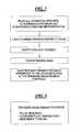
- FIG. 2is a flowchart of the basic steps for generating a standard measurement protocol in accordance with the invention.
- FIG. 3illustrates the basic components or content of the standard measurement protocol in accordance with the invention.
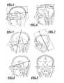
- FIG. 4illustrates the positioning of the slicebox relative to a standard head in a standard measurement protocol produced in accordance with the invention for a brain scan (brain standard).
- FIG. 5illustrates the positioning of the slicebox relative to a standard head in a standard measurement protocol produced in accordance with the invention for a pituitary gland scan (pituitary standard).
- FIG. 6illustrates the positioning of the slicebox relative to a standard head in a standard measurement protocol produced in accordance with the invention for a fMRI scan (fMRI standard).
- FIG. 7illustrates the positioning of the slicebox relative to a standard head in a standard measurement protocol produced in accordance with the invention for a epilepsy scan (epilepsy standard).
- FIG. 8illustrates the positioning of the slicebox relative to a standard head in a standard measurement protocol produced in accordance with the invention for a optic nerve scan (optic nerve standard).
- FIG. 9illustrates the positioning of the slicebox relative to a standard head in a standard measurement protocol produced in accordance with the invention for a acoustic nerve scan (acoustic nerve standard).
- FIG. 10is a flowchart of the inventive method for producing a patient-specific measurement protocol.
- FIGS. 11A , 11 B and 11 Care exemplary illustrations for explaining the inventive method of FIG. 10 .
- FIG. 1schematically illustrates a magnetic resonance imaging (tomography) apparatus for generating a magnetic resonance image of a subject, as an example of a tomographic imaging modality operable according to the present invention.
- the components of the nuclear magnetic resonance tomography apparatuscorrespond to those of a conventional tomography apparatus, but it is controlled according to the invention.
- a basic field magnet 1generates a time-constant, intense magnetic field for polarization (alignment) of the nuclear spins in the examination region of a subject such as, for example, a part of a human body to be examined.
- the high homogeneity of the basic magnetic field required for the nuclear magnetic resonance measurementis defined in a spherical measurement volume M in which the part of the human body to be examined is introduced.
- shim plates of ferromagnetic materialare attached at suitable locations. Time-variable influences are eliminated by shim coils 2 that are driven by a shim power supply 15 .
- a cylindrical gradient coil system 3is built into the basic field magnet 1 , the system 3 being composed of three sub-windings. Each sub-winding is supplied with current by an amplifier 14 for generating a linear gradient field in the respective directions of a Cartesian coordinate system.
- the first, sub-winding of the gradient field system 3generates a gradient G x in the x-direction
- the second sub-windinggenerates a gradient G y in the y-direction
- the third sub-windinggenerates a gradient G z in the z-direction.
- Each amplifier 14has a digital-to-analog converter DAC that is driven by a sequence control 18 for the time-controlled generation of gradient pulses.
- a radio-frequency antenna 4is situated within the gradient field system 3 .
- the antenna 4converts the radio-frequency pulses emitted by a radio-frequency power amplifier into an alternating magnetic field for exciting the nuclei and aligning the nuclear spins of the subject under examination, or of a region of the subject under examination.
- the radio-frequency antenna 4is composed of one or more RF transmission coils and a number of RF reception coils in the form of an arrangement (preferably linear) of component coils.
- the nuclear spin echo signals produced as a rule by a pulse sequence composed of one or more radio-frequency pulses and one or more gradient pulsesis also converted into a voltage by the RF reception coils of the radio-frequency antenna 4 , this voltage being supplied via an amplifier 7 to a radio-frequency reception channel 8 of a radio-frequency system 22 .
- the radio-frequency system 22also has a transmission channel 9 wherein the radio-frequency pulses are generated for exciting magnetic nuclear resonance.
- the respective radio-frequency pulsesare digitally presented as a sequence of complex numbers on the basis of a pulse sequence in the sequence control 18 prescribed by the system computer 20 .
- This number sequence(as a real part and an imaginary part—is supplied via respective inputs 12 to a digital-to-analog converter DAC in the radio-frequency system 22 and is supplied from there to a transmission channel 9 .
- the pulse sequencesare modulated onto a radio-frequency carrier signal having a basic frequency corresponding to the resonant frequency of the nuclear spins in the measurement volume.
- the switching from transmission mode to reception modeensues via a transmission/reception diplexer 6 .
- the RF transmission coil of the radio-frequency antenna 4radiates the radio-frequency pulses, based on signals from a radio-frequency power amplifier 16 , for excitation of the nuclear spins into the measurement volume M and samples the resulting echo signals via the RF reception coils.
- the acquired nuclear magnetic resonance signalsare phase-sensitively demodulated in the reception channel 8 of the radio-frequency system 22 and are converted via respective analog-to-digital converters ADC into the real part and the imaginary part of the measured signal, which are respectively supplied to outputs 11 .
- An image computer 17reconstructs an image from the measured data acquired in this way. Administration of the measured data, the image data and the control programs ensues via the system computer 20 .
- the sequence control 18monitors the generation of the respectively desired pulse sequences and the corresponding sampling of k-space.
- the sequence control 18controls the timed switching of the gradients, the emission of the radio-frequency pulses with defined phase and amplitude, as well as the reception of the nuclear magnetic resonance signals.
- the timing signals for the radio-frequency system 22 and the sequence control 18is made available by a synthesizer 19 .
- the selection of corresponding control programs for generating a nuclear magnetic resonance image as well as the presentation of the generated nuclear magnetic resonance imageensues via a terminal 21 that has a keyboard as well as one or more picture screens.
- the inventive methodcan be executed using the terminal 21 and the system computer 20 .
- the system computer 20can either have stored therein, or have access to, an atlas of anatomical organs.
- a number of such atlasesare commercially available and/or accessible on-line.
- Such an atlascontains a statistical dataset for each of a number of different anatomical organs.
- the atlas or statistical dataset of the organ which will be imaged in the scanis loaded, accessed or retrieved and the particular field of interest in the scan is designated.
- the imaging areais then designed, and the relevant parameters that have been entered are stored together with a reference to the atlas that was employed in producing this standard measurement protocol.
- FIG. 3The basic contents of the standard measurement protocol for each type of scan that is developed according to the flowchart shown in FIG. 2 are presented in FIG. 3 . These components include the pulse sequence that will be used in the scan, the coordinates of the imaging area, and a reference to the atlas that was used in producing the protocol.
- the region in which the slice or slices in the scan will be obtainedis known as the “slicebox.”
- the orientation of the slicebox for a number of different standard measurement protocols produced in accordance with the inventionare shown with reference to a standard head in FIGS. 4 through 9 .
- FIG. 4illustrates the orientation of the slicebox relative to the standard head (head atlas) for a brain scan (brain standard).
- FIG. 5shows the orientation of the slicebox for a scan of the pituitary gland (pituitary standard).
- FIG. 6shows the orientation of the slicebox for functional magnetic resonance imaging (fMRI standard).
- fMRI standardfunctional magnetic resonance imaging
- FIG. 7illustrates the orientation of the slicebox relative to the standard head for a scan to detect symptoms in the brain indicative of epilepsy (epilepsy standard).
- FIG. 8illustrates the orientation of the slicebox (here, as in FIG. 5 , a single slice) for a scan of the optic nerves (optic nerve standard) and
- FIG. 9illustrates the slicebox for a scan of the auditory nerves (auditory nerve standard).
- the standard measurement protocolis used in the method illustrated in FIG. 10 for producing a patient-specific measurement protocol.
- a patient datasetis created with an auto align sequence, which represents the actual position of the patient in the scanner for a particular examination.
- the patient datasetis statistically analyzed, and the appropriate standard measurement protocol, for among the standard measurement protocols generated as described above, is selected.
- the statistical dataset (atlas) that is referenced in the selected standard measurement protocolis then loaded (or accessed or retrieved).
- a transformation matrixis then calculated which provides a mapping between the statistical dataset and the patient dataset.
- the standard measurement protocolis then transformed or converted, using the transformation matrix, to a patient-specific measurement protocol for the particular patient and the particular scan.
- FIGS. 11A , 11 B and 11 CThe procedure set forth in the flowchart of FIG. 10 is illustrated in the sequence shown in FIGS. 11A , 11 B and 11 C.
- the illustrations that are schematically shown in FIGS. 11A , 11 B and 11 Cmay be visually displayed at the screen of the terminal 21 , if desired, however, since it is not critical for the operator to actually view these representations, FIGS. 11A , 11 B and 11 C can be considered as schematic illustrations of the data manipulations that are taking place in the computer during the execution of the inventive method.
- FIG. 11Ashows a standard head (head atlas) in three different views with the standard measurement protocol (SMP) slicebox indicated relative to the standard head.
- SMPstandard measurement protocol
- FIG. 11Bshows the same views of the head, but these views are obtained from the low-resolution scan of the actual patient in the scanning apparatus.
- the orientation of the organ of interest, in this case the patient headwill almost certainly be different from the orientation of the standard head shown in FIG. 11 A.
- the SMP sliceboxis shown in each view in a position that is identical to the slice box position in FIG. 11 A. Since the actual position of the patient head is different from the position of the standard head, the SMP slicebox would not be properly oriented relative to the actual patient head for conducting the desired scan.
- the aforementioned transformation matrixis generated, which represents a mapping between the standard head and the patient head.
- the data representing the SMP slicebox in FIG. 11Bare then operated on by the transformation matrix, thereby producing a transformed slicebox shown in FIG. 11 C.
- This transformed sliceboxhas the same orientation relative to the patient head as the SMP slicebox has relative to the standard head.
- FIG. 11Ctherefore represents the resulting patient specific measurement protocol at the end of the flowchart in FIG. 10 .
- the actual diagnostic scancan then be conducted using this patient-specific measurement protocol.
Landscapes
- Health & Medical Sciences (AREA)
- Life Sciences & Earth Sciences (AREA)
- Nuclear Medicine, Radiotherapy & Molecular Imaging (AREA)
- Physics & Mathematics (AREA)
- Engineering & Computer Science (AREA)
- Medical Informatics (AREA)
- Heart & Thoracic Surgery (AREA)
- Surgery (AREA)
- Biophysics (AREA)
- Biomedical Technology (AREA)
- Radiology & Medical Imaging (AREA)
- High Energy & Nuclear Physics (AREA)
- Molecular Biology (AREA)
- Pathology (AREA)
- Animal Behavior & Ethology (AREA)
- General Health & Medical Sciences (AREA)
- Public Health (AREA)
- Veterinary Medicine (AREA)
- Optics & Photonics (AREA)
- Magnetic Resonance Imaging Apparatus (AREA)
Abstract
Description
Claims (23)
Priority Applications (5)
| Application Number | Priority Date | Filing Date | Title |
|---|---|---|---|
| US10/691,405US6952097B2 (en) | 2003-10-22 | 2003-10-22 | Method for slice position planning of tomographic measurements, using statistical images |
| DE102004051169ADE102004051169A1 (en) | 2003-10-22 | 2004-10-20 | Method for cutting position plots of tomographic measurements using statistical images |
| JP2004307138AJP4863610B2 (en) | 2003-10-22 | 2004-10-21 | Method for creating a standard measurement protocol for a tomographic imaging system, a computer readable recording medium recording a computer program, and a planning method for positioning an imaging range of an actual object in the tomographic imaging system |
| KR1020040084272AKR100828220B1 (en) | 2003-10-22 | 2004-10-21 | Method for slice position planning of tomographic measurements, using statistical images |
| CNB2004101033009ACN100471454C (en) | 2003-10-22 | 2004-10-22 | A Method for Measuring Fault Locations Using Statistical Image Planning Tomography |
Applications Claiming Priority (1)
| Application Number | Priority Date | Filing Date | Title |
|---|---|---|---|
| US10/691,405US6952097B2 (en) | 2003-10-22 | 2003-10-22 | Method for slice position planning of tomographic measurements, using statistical images |
Publications (2)
| Publication Number | Publication Date |
|---|---|
| US20050088177A1 US20050088177A1 (en) | 2005-04-28 |
| US6952097B2true US6952097B2 (en) | 2005-10-04 |
Family
ID=34465624
Family Applications (1)
| Application Number | Title | Priority Date | Filing Date |
|---|---|---|---|
| US10/691,405Expired - LifetimeUS6952097B2 (en) | 2003-10-22 | 2003-10-22 | Method for slice position planning of tomographic measurements, using statistical images |
Country Status (5)
| Country | Link |
|---|---|
| US (1) | US6952097B2 (en) |
| JP (1) | JP4863610B2 (en) |
| KR (1) | KR100828220B1 (en) |
| CN (1) | CN100471454C (en) |
| DE (1) | DE102004051169A1 (en) |
Cited By (13)
| Publication number | Priority date | Publication date | Assignee | Title |
|---|---|---|---|---|
| US20040122307A1 (en)* | 2001-11-21 | 2004-06-24 | Shraga Rottem | Method and system for enhancing the quality of device images |
| US20050154292A1 (en)* | 2003-12-08 | 2005-07-14 | Martin Tank | Method and control device to operate a magnetic resonance tomography apparatus |
| US20070165930A1 (en)* | 2006-01-16 | 2007-07-19 | Ute Feuerlein | Method and medical imaging apparatus for adjusting operating and evaluation parameters of the apparatus |
| US20080103383A1 (en)* | 2006-10-23 | 2008-05-01 | Andre Van Der Kouwe | Selective MR imaging of segmented anatomy |
| US7450983B2 (en) | 2003-03-18 | 2008-11-11 | University Of Cincinnati | Automated brain MRI and CT prescriptions in Talairach space |
| US20080284432A1 (en)* | 2007-05-18 | 2008-11-20 | Juergen Nistler | Method for controlling a magnetic resonance system |
| US20090297011A1 (en)* | 2008-05-28 | 2009-12-03 | Thomas Brunner | Method for obtaining a 3d (ct) image using a c-arm x-ray imaging system via rotational acquisition about a selectable 3d acquisition axis |
| US20100004527A1 (en)* | 2008-07-01 | 2010-01-07 | Dale Anders M | Identifying White Matter Fiber Tracts Using Magnetic Resonance Imaging (MRI) |
| US20100129005A1 (en)* | 2008-11-26 | 2010-05-27 | General Electric Company | System and method for automated scan planning using symmetry detection and image registration |
| US20110178384A1 (en)* | 2010-01-21 | 2011-07-21 | Rainer Kuth | System with at least one medical imaging device, and method to prepare a sample for medical imaging |
| US9404986B2 (en) | 2011-05-06 | 2016-08-02 | The Regents Of The University Of California | Measuring biological tissue parameters using diffusion magnetic resonance imaging |
| US10149632B2 (en) | 2013-10-01 | 2018-12-11 | Toshiba Medical Systems Corporation | Magnetic resonance imaging apparatus and imaging planning method |
| US10317492B2 (en) | 2015-03-30 | 2019-06-11 | Siemens Aktiengesellschaft | Magnetic resonance data acquisition method and apparatus saturation with spin dependent on the anatomical structures to be imaged |
Families Citing this family (51)
| Publication number | Priority date | Publication date | Assignee | Title |
|---|---|---|---|---|
| DE102005018349B4 (en)* | 2005-04-20 | 2010-09-09 | Siemens Ag | Method for determining the position of a patient in a magnetic resonance apparatus and a magnetic resonance device |
| US8926959B2 (en) | 2005-07-22 | 2015-01-06 | The Board Of Trustees Of The Leland Stanford Junior University | System for optical stimulation of target cells |
| US9238150B2 (en) | 2005-07-22 | 2016-01-19 | The Board Of Trustees Of The Leland Stanford Junior University | Optical tissue interface method and apparatus for stimulating cells |
| US9274099B2 (en) | 2005-07-22 | 2016-03-01 | The Board Of Trustees Of The Leland Stanford Junior University | Screening test drugs to identify their effects on cell membrane voltage-gated ion channel |
| US10052497B2 (en) | 2005-07-22 | 2018-08-21 | The Board Of Trustees Of The Leland Stanford Junior University | System for optical stimulation of target cells |
| EP2465925A1 (en) | 2005-07-22 | 2012-06-20 | The Board Of Trustees Of The Leland | Light-activated cation channel and uses thereof |
| US20090093403A1 (en) | 2007-03-01 | 2009-04-09 | Feng Zhang | Systems, methods and compositions for optical stimulation of target cells |
| DE102005044652B4 (en)* | 2005-09-19 | 2009-12-10 | Siemens Ag | Method for generating 2D reconstruction images from a 3D image data set of an examination object, in particular taken by means of a magnetic resonance device, in the context of image post-processing |
| US20070081706A1 (en)* | 2005-09-28 | 2007-04-12 | Xiang Zhou | Systems and methods for computer aided diagnosis and decision support in whole-body imaging |
| CN100458805C (en)* | 2006-01-20 | 2009-02-04 | 上海西门子医疗器械有限公司 | Management system and method for scan protocols |
| DE102006006309B4 (en)* | 2006-02-10 | 2017-01-26 | Siemens Healthcare Gmbh | Method for operating a magnetic resonance device and magnetic resonance device for carrying out the method |
| US8398692B2 (en) | 2007-01-10 | 2013-03-19 | The Board Of Trustees Of The Leland Stanford Junior University | System for optical stimulation of target cells |
| US8401609B2 (en) | 2007-02-14 | 2013-03-19 | The Board Of Trustees Of The Leland Stanford Junior University | System, method and applications involving identification of biological circuits such as neurological characteristics |
| US10035027B2 (en) | 2007-10-31 | 2018-07-31 | The Board Of Trustees Of The Leland Stanford Junior University | Device and method for ultrasonic neuromodulation via stereotactic frame based technique |
| US10434327B2 (en) | 2007-10-31 | 2019-10-08 | The Board Of Trustees Of The Leland Stanford Junior University | Implantable optical stimulators |
| KR100959630B1 (en)* | 2007-12-12 | 2010-05-27 | 경희대학교 산학협력단 | Data transmission method in wireless sensor network |
| EP3165534B1 (en) | 2008-04-23 | 2018-09-26 | The Board of Trustees of The Leland Stanford Junior University | Systems, methods and compositions for optical stimulation of target cells |
| JP5598832B2 (en)* | 2008-05-23 | 2014-10-01 | 株式会社日立メディコ | Magnetic resonance imaging apparatus and method |
| CN102076866A (en) | 2008-05-29 | 2011-05-25 | 利兰·斯坦福青年大学托管委员会 | Cell lines, systems and methods for optically controlling second messengers |
| SG191604A1 (en) | 2008-06-17 | 2013-07-31 | Univ Leland Stanford Junior | Apparatus and methods for controlling cellular development |
| US9101759B2 (en) | 2008-07-08 | 2015-08-11 | The Board Of Trustees Of The Leland Stanford Junior University | Materials and approaches for optical stimulation of the peripheral nervous system |
| NZ602416A (en) | 2008-11-14 | 2014-08-29 | Univ Leland Stanford Junior | Optically-based stimulation of target cells and modifications thereto |
| ES2676274T3 (en) | 2010-03-17 | 2018-07-18 | The Board Of Trustees Of The Leland Stanford Junior University | Light sensitive molecules that allow the passage of ions |
| WO2012008296A1 (en)* | 2010-07-15 | 2012-01-19 | 株式会社 日立メディコ | Medical image capture device and image capture slice determination method |
| EP2635295B1 (en) | 2010-11-05 | 2017-12-20 | The Board of Trustees of the Leland Stanford Junior University | Control and characterization of memory function |
| WO2012061744A2 (en) | 2010-11-05 | 2012-05-10 | The Board Of Trustees Of The Leland Stanford Junior University | Stabilized step function opsin proteins and methods of using the same |
| EP2635346B1 (en) | 2010-11-05 | 2017-03-29 | The Board of Trustees of the Leland Stanford Junior University | Optogenetic control of reward-related behaviors |
| EP2635341B1 (en) | 2010-11-05 | 2018-08-08 | The Board of Trustees of the Leland Stanford Junior University | Upconversion of light for use in optogenetic methods |
| JP6276591B2 (en) | 2010-11-05 | 2018-02-07 | ザ ボード オブ トラスティーズ オブ ザ レランド スタンフォード ジュニア ユニバーシティー | Photo-activated chimeric opsin and method of use thereof |
| EP2635109A4 (en) | 2010-11-05 | 2014-03-19 | Univ Leland Stanford Junior | OPTICALLY CONTROLLED CNS DYSFUNCTION |
| US8696722B2 (en) | 2010-11-22 | 2014-04-15 | The Board Of Trustees Of The Leland Stanford Junior University | Optogenetic magnetic resonance imaging |
| KR101048605B1 (en)* | 2010-11-26 | 2011-07-12 | 한국지질자원연구원 | Volumetric foreign body volume measurement device and method using a computed tomography system |
| WO2013027540A1 (en) | 2011-08-25 | 2013-02-28 | 株式会社日立メディコ | Medical image imaging device |
| JP6406581B2 (en) | 2011-12-16 | 2018-10-17 | ザ ボード オブ トラスティーズ オブ ザ レランド スタンフォード ジュニア ユニバーシティー | Opsin polypeptides and uses thereof |
| US20140024701A1 (en) | 2012-02-21 | 2014-01-23 | Circuit Therapeutics, Inc. | Compositions and Methods for Treating Neurogenic Disorders of the Pelvic Floor |
| EP2968997B1 (en) | 2013-03-15 | 2019-06-26 | The Board of Trustees of the Leland Stanford Junior University | Optogenetic control of behavioral state |
| US9636380B2 (en) | 2013-03-15 | 2017-05-02 | The Board Of Trustees Of The Leland Stanford Junior University | Optogenetic control of inputs to the ventral tegmental area |
| CN105431046B (en) | 2013-04-29 | 2020-04-17 | 小利兰·斯坦福大学托管委员会 | Devices, systems, and methods for optogenetic modulation of action potentials in target cells |
| EP3033427A4 (en) | 2013-08-14 | 2017-05-31 | The Board Of Trustees Of The University Of the Leland Stanford Junior University | Compositions and methods for controlling pain |
| DE102014211130B4 (en) | 2014-06-11 | 2016-05-12 | Siemens Aktiengesellschaft | Automatically determining a slice position for a magnetic resonance examination |
| CN105654519B (en)* | 2014-11-11 | 2019-06-04 | 阿里巴巴集团控股有限公司 | Spatial position determines the method and device thereof of geometric object |
| US10568516B2 (en) | 2015-06-22 | 2020-02-25 | The Board Of Trustees Of The Leland Stanford Junior University | Methods and devices for imaging and/or optogenetic control of light-responsive neurons |
| KR101666834B1 (en)* | 2015-08-07 | 2016-10-17 | 서울여자대학교 산학협력단 | Anterior Cruciate Ligament Segmentation Method in Knee MRI and Apparatus |
| CN105054959B (en) | 2015-08-12 | 2018-06-15 | 沈阳东软医疗系统有限公司 | Air correction method, apparatus and equipment |
| JP6677256B2 (en)* | 2015-09-02 | 2020-04-08 | 富士通株式会社 | Image interpretation support program, cross-sectional image generating device, and cross-sectional image generating method |
| DE102017202601A1 (en)* | 2017-02-17 | 2018-08-23 | Siemens Healthcare Gmbh | Determination of marks on quantitative image data |
| DE102017203025A1 (en)* | 2017-02-24 | 2018-08-30 | Siemens Healthcare Gmbh | A method of assisting in planning a magnetic resonance examination on a patient having a magnetic resonance apparatus, and a magnetic resonance apparatus for performing the method |
| US11294165B2 (en) | 2017-03-30 | 2022-04-05 | The Board Of Trustees Of The Leland Stanford Junior University | Modular, electro-optical device for increasing the imaging field of view using time-sequential capture |
| TWI714855B (en)* | 2018-03-01 | 2021-01-01 | 鴻海精密工業股份有限公司 | Head-mounted magnetic resonance imaging device and dementia monitor system |
| EP3543723A1 (en) | 2018-03-20 | 2019-09-25 | Siemens Healthcare GmbH | Method for acquiring magnetic resonance image data for image-guided radiotherapy |
| CN113534282B (en)* | 2020-04-18 | 2024-03-29 | 中国石油化工股份有限公司 | Fault activity frequency calculating method based on lithology vs. difference |
Citations (12)
| Publication number | Priority date | Publication date | Assignee | Title |
|---|---|---|---|---|
| US5231651A (en) | 1990-03-30 | 1993-07-27 | Kabushiki Kaisha Toshiba | X-ray computerized tomographic method and apparatus with simple programmable anatomical selecting operation |
| US5398684A (en)* | 1988-12-23 | 1995-03-21 | Hardy; Tyrone L. | Method and apparatus for video presentation from scanner imaging sources |
| US5512827A (en)* | 1995-06-02 | 1996-04-30 | General Electric Company | Scan control platform-based interactive image plane prescription for MRI |
| US6195409B1 (en) | 1998-05-22 | 2001-02-27 | Harbor-Ucla Research And Education Institute | Automatic scan prescription for tomographic imaging |
| US6275035B1 (en)* | 1998-11-25 | 2001-08-14 | General Electric Company | Method for using three points to define a 2D MR imaging section |
| WO2001059708A1 (en) | 2000-02-11 | 2001-08-16 | Btg International Limited | Method of 3d/2d registration of object views to a surface model |
| US6348793B1 (en)* | 2000-11-06 | 2002-02-19 | Ge Medical Systems Global Technology, Company, Llc | System architecture for medical imaging systems |
| WO2002043003A1 (en) | 2000-11-24 | 2002-05-30 | Kent Ridge Digital Labs | Methods and apparatus for processing medical images |
| US20020087061A1 (en) | 2000-12-28 | 2002-07-04 | Ilan Lifshitz | Operator interface for a medical diagnostic imaging device |
| US20020172408A1 (en) | 2001-05-18 | 2002-11-21 | Motoaki Saito | Displaying three-dimensional medical images |
| WO2002098292A1 (en) | 2001-06-07 | 2002-12-12 | The University Of Sydney | A map of a property |
| US20030139659A1 (en) | 2002-01-22 | 2003-07-24 | Cortechs | Atlas and methods for segmentation and alignment of anatomical data |
Family Cites Families (4)
| Publication number | Priority date | Publication date | Assignee | Title |
|---|---|---|---|---|
| JPH04141157A (en)* | 1990-10-02 | 1992-05-14 | Toshiba Corp | Ultrasound diagnostic equipment |
| JPH05161643A (en)* | 1991-12-10 | 1993-06-29 | Hitachi Medical Corp | Ultrasonic diagnostic device |
| DE19943404B4 (en)* | 1999-09-10 | 2009-10-15 | Siemens Ag | Method for operating an MR tomography device |
| WO2002091924A1 (en)* | 2001-05-16 | 2002-11-21 | Koninklijke Philips Electronics N.V. | Automatic prescription of tomographic parameters |
- 2003
- 2003-10-22USUS10/691,405patent/US6952097B2/ennot_activeExpired - Lifetime
- 2004
- 2004-10-20DEDE102004051169Apatent/DE102004051169A1/ennot_activeWithdrawn
- 2004-10-21JPJP2004307138Apatent/JP4863610B2/ennot_activeExpired - Fee Related
- 2004-10-21KRKR1020040084272Apatent/KR100828220B1/ennot_activeExpired - Fee Related
- 2004-10-22CNCNB2004101033009Apatent/CN100471454C/ennot_activeExpired - Fee Related
Patent Citations (12)
| Publication number | Priority date | Publication date | Assignee | Title |
|---|---|---|---|---|
| US5398684A (en)* | 1988-12-23 | 1995-03-21 | Hardy; Tyrone L. | Method and apparatus for video presentation from scanner imaging sources |
| US5231651A (en) | 1990-03-30 | 1993-07-27 | Kabushiki Kaisha Toshiba | X-ray computerized tomographic method and apparatus with simple programmable anatomical selecting operation |
| US5512827A (en)* | 1995-06-02 | 1996-04-30 | General Electric Company | Scan control platform-based interactive image plane prescription for MRI |
| US6195409B1 (en) | 1998-05-22 | 2001-02-27 | Harbor-Ucla Research And Education Institute | Automatic scan prescription for tomographic imaging |
| US6275035B1 (en)* | 1998-11-25 | 2001-08-14 | General Electric Company | Method for using three points to define a 2D MR imaging section |
| WO2001059708A1 (en) | 2000-02-11 | 2001-08-16 | Btg International Limited | Method of 3d/2d registration of object views to a surface model |
| US6348793B1 (en)* | 2000-11-06 | 2002-02-19 | Ge Medical Systems Global Technology, Company, Llc | System architecture for medical imaging systems |
| WO2002043003A1 (en) | 2000-11-24 | 2002-05-30 | Kent Ridge Digital Labs | Methods and apparatus for processing medical images |
| US20020087061A1 (en) | 2000-12-28 | 2002-07-04 | Ilan Lifshitz | Operator interface for a medical diagnostic imaging device |
| US20020172408A1 (en) | 2001-05-18 | 2002-11-21 | Motoaki Saito | Displaying three-dimensional medical images |
| WO2002098292A1 (en) | 2001-06-07 | 2002-12-12 | The University Of Sydney | A map of a property |
| US20030139659A1 (en) | 2002-01-22 | 2003-07-24 | Cortechs | Atlas and methods for segmentation and alignment of anatomical data |
Cited By (18)
| Publication number | Priority date | Publication date | Assignee | Title |
|---|---|---|---|---|
| US20040122307A1 (en)* | 2001-11-21 | 2004-06-24 | Shraga Rottem | Method and system for enhancing the quality of device images |
| US7421140B2 (en)* | 2001-11-21 | 2008-09-02 | Shraga Rottem | Method and system for enhancing the quality of device images |
| US7450983B2 (en) | 2003-03-18 | 2008-11-11 | University Of Cincinnati | Automated brain MRI and CT prescriptions in Talairach space |
| US20050154292A1 (en)* | 2003-12-08 | 2005-07-14 | Martin Tank | Method and control device to operate a magnetic resonance tomography apparatus |
| US20070165930A1 (en)* | 2006-01-16 | 2007-07-19 | Ute Feuerlein | Method and medical imaging apparatus for adjusting operating and evaluation parameters of the apparatus |
| US8831703B2 (en)* | 2006-10-23 | 2014-09-09 | The General Hospital Corporation | Selective MR imaging of segmented anatomy |
| US20080103383A1 (en)* | 2006-10-23 | 2008-05-01 | Andre Van Der Kouwe | Selective MR imaging of segmented anatomy |
| US20080284432A1 (en)* | 2007-05-18 | 2008-11-20 | Juergen Nistler | Method for controlling a magnetic resonance system |
| US7847554B2 (en) | 2007-05-18 | 2010-12-07 | Siemens Aktiengesellschaft | Method for controlling a magnetic resonance system |
| US20090297011A1 (en)* | 2008-05-28 | 2009-12-03 | Thomas Brunner | Method for obtaining a 3d (ct) image using a c-arm x-ray imaging system via rotational acquisition about a selectable 3d acquisition axis |
| US20100004527A1 (en)* | 2008-07-01 | 2010-01-07 | Dale Anders M | Identifying White Matter Fiber Tracts Using Magnetic Resonance Imaging (MRI) |
| US9568580B2 (en) | 2008-07-01 | 2017-02-14 | The Regents Of The University Of California | Identifying white matter fiber tracts using magnetic resonance imaging (MRI) |
| US20100129005A1 (en)* | 2008-11-26 | 2010-05-27 | General Electric Company | System and method for automated scan planning using symmetry detection and image registration |
| US20110178384A1 (en)* | 2010-01-21 | 2011-07-21 | Rainer Kuth | System with at least one medical imaging device, and method to prepare a sample for medical imaging |
| US9404986B2 (en) | 2011-05-06 | 2016-08-02 | The Regents Of The University Of California | Measuring biological tissue parameters using diffusion magnetic resonance imaging |
| US10149632B2 (en) | 2013-10-01 | 2018-12-11 | Toshiba Medical Systems Corporation | Magnetic resonance imaging apparatus and imaging planning method |
| US10729355B2 (en) | 2013-10-01 | 2020-08-04 | Canon Medical Systems Corporation | Magnetic resonance imaging apparatus and imaging planning method |
| US10317492B2 (en) | 2015-03-30 | 2019-06-11 | Siemens Aktiengesellschaft | Magnetic resonance data acquisition method and apparatus saturation with spin dependent on the anatomical structures to be imaged |
Also Published As
| Publication number | Publication date |
|---|---|
| KR20050039601A (en) | 2005-04-29 |
| DE102004051169A1 (en) | 2005-05-19 |
| KR100828220B1 (en) | 2008-05-07 |
| CN100471454C (en) | 2009-03-25 |
| CN1650808A (en) | 2005-08-10 |
| JP4863610B2 (en) | 2012-01-25 |
| US20050088177A1 (en) | 2005-04-28 |
| JP2005125099A (en) | 2005-05-19 |
Similar Documents
| Publication | Publication Date | Title |
|---|---|---|
| US6952097B2 (en) | Method for slice position planning of tomographic measurements, using statistical images | |
| EP3333583B1 (en) | Method for identifying an organ structure of an investigated object in magnetic resonance image data | |
| US7379573B2 (en) | Method and apparatus for processing images using three-dimensional ROI | |
| US4585992A (en) | NMR imaging methods | |
| US7768263B2 (en) | Magnetic resonance imaging apparatus and method | |
| US8831703B2 (en) | Selective MR imaging of segmented anatomy | |
| US9250307B2 (en) | Magnetic resonance system and method to generate diffusion information | |
| US6828788B2 (en) | Apparatus and method for magnetic resonance imaging using partial parallel acquisition (PPA) | |
| JP2014503249A (en) | MR imaging using multipoint Dixon technology | |
| JPH06259559A (en) | Analyzing method of picture | |
| US20120038673A1 (en) | Magnetic resonance imaging apparatus and method for displaying running direction of fibrous tissue | |
| CN106419917B (en) | The method and apparatus for doing prospective motion correction with volume navigation in magnetic resonance imaging | |
| JP5575454B2 (en) | Magnetic resonance imaging system | |
| JP2015525601A (en) | Magnetic resonance system and magnetic resonance method | |
| US20240090791A1 (en) | Anatomy Masking for MRI | |
| US20100092056A1 (en) | Mri systems and realated methods | |
| US6546273B2 (en) | MR fluoroscopy method and apparatus | |
| WO2001084172A1 (en) | Prospective multi-planar motion correction in mri | |
| US20140320128A1 (en) | Method and magnetic resonance apparatus to acquire image data sets of an examination subject | |
| US10143853B2 (en) | Magnetic resonance method and apparatus for planning a brachytherapy treatment using an image with hyperintense contrast to identify the position of a brachytherapy applicator | |
| US7245752B2 (en) | Method, tomography apparatus and software product for evaluation of time-varying diagnostic procedures | |
| US6683453B2 (en) | Magnetic resonance apparatus for obtaining NMR navigator echoes with slight disturbance of the longitudinal magnetization | |
| US20040162482A1 (en) | MRT apparatus, method and computer program product for speed-resolved flow measurement | |
| JP2023508768A (en) | MR imaging for radiotherapy planning | |
| CN114305385A (en) | Magnetic resonance imaging device, object alignment device, and object alignment method |
Legal Events
| Date | Code | Title | Description |
|---|---|---|---|
| AS | Assignment | Owner name:SIEMENS AKTIENGESELLSCHAFT, GERMANY Free format text:ASSIGNMENT OF ASSIGNORS INTEREST;ASSIGNORS:SCHRECK, OLIVER;MULLER, MIKE;HARDER, MARTIN;AND OTHERS;REEL/FRAME:015566/0520;SIGNING DATES FROM 20040415 TO 20040422 | |
| AS | Assignment | Owner name:GENERAL HOSPITAL CORPORATION, MASSACHUSETTS Free format text:ASSIGNMENT OF ASSIGNORS INTEREST;ASSIGNORS:ANDERS, DALE;VAN DER KOUWE, ANDRE;REEL/FRAME:015995/0377;SIGNING DATES FROM 20040510 TO 20041115 | |
| STCF | Information on status: patent grant | Free format text:PATENTED CASE | |
| AS | Assignment | Owner name:NATIONAL INSTITUTES OF HEALTH (NIH), U.S. DEPT. OF Free format text:EXECUTIVE ORDER 9424, CONFIRMATORY LICENSE;ASSIGNOR:GENERAL HOSPITAL CORPORATION DBA MASS;REEL/FRAME:021344/0302 Effective date:20040423 | |
| FPAY | Fee payment | Year of fee payment:4 | |
| FPAY | Fee payment | Year of fee payment:8 | |
| AS | Assignment | Owner name:SIEMENS HEALTHCARE GMBH, GERMANY Free format text:ASSIGNMENT OF ASSIGNORS INTEREST;ASSIGNOR:SIEMENS AKTIENGESELLSCHAFT;REEL/FRAME:038959/0375 Effective date:20160513 | |
| FPAY | Fee payment | Year of fee payment:12 | |
| AS | Assignment | Owner name:SIEMENS HEALTHINEERS AG, GERMANY Free format text:ASSIGNMENT OF ASSIGNORS INTEREST;ASSIGNOR:SIEMENS HEALTHCARE GMBH;REEL/FRAME:066088/0256 Effective date:20231219 | |
| AS | Assignment | Owner name:SIEMENS HEALTHINEERS AG, GERMANY Free format text:CORRECTIVE ASSIGNMENT TO CORRECT THE ASSIGNEE PREVIOUSLY RECORDED AT REEL: 066088 FRAME: 0256. ASSIGNOR(S) HEREBY CONFIRMS THE ASSIGNMENT;ASSIGNOR:SIEMENS HEALTHCARE GMBH;REEL/FRAME:071178/0246 Effective date:20231219 |