US6950650B2 - System and method for call forwarding synchronization in a communication system - Google Patents
System and method for call forwarding synchronization in a communication systemDownload PDFInfo
- Publication number
- US6950650B2 US6950650B2US09/781,927US78192701AUS6950650B2US 6950650 B2US6950650 B2US 6950650B2US 78192701 AUS78192701 AUS 78192701AUS 6950650 B2US6950650 B2US 6950650B2
- Authority
- US
- United States
- Prior art keywords
- call forwarding
- destination
- mobile station
- forwarding destination
- subsystem
- Prior art date
- Legal status (The legal status is an assumption and is not a legal conclusion. Google has not performed a legal analysis and makes no representation as to the accuracy of the status listed.)
- Expired - Lifetime, expires
Links
- 238000000034methodMethods0.000titleclaimsabstractdescription67
- 238000004891communicationMethods0.000titleclaimsdescription55
- 230000006854communicationEffects0.000titleclaimsdescription55
- 230000008859changeEffects0.000claimsabstractdescription14
- 230000004044responseEffects0.000claimsabstractdescription10
- 230000004913activationEffects0.000claimsdescription8
- 230000011664signalingEffects0.000claimsdescription8
- 230000001360synchronised effectEffects0.000claimsdescription4
- 238000010295mobile communicationMethods0.000claimsdescription2
- 238000010586diagramMethods0.000description28
- 238000012544monitoring processMethods0.000description7
- 238000012546transferMethods0.000description6
- 230000008901benefitEffects0.000description5
- 230000006870functionEffects0.000description5
- 230000032258transportEffects0.000description5
- 101000667353Homo sapiens von Willebrand factor A domain-containing protein 1Proteins0.000description2
- 230000004075alterationEffects0.000description2
- 230000005540biological transmissionEffects0.000description2
- 230000009977dual effectEffects0.000description2
- 238000012986modificationMethods0.000description2
- 230000004048modificationEffects0.000description2
- 238000006467substitution reactionMethods0.000description2
- 102100039759von Willebrand factor A domain-containing protein 1Human genes0.000description2
- 230000007175bidirectional communicationEffects0.000description1
- 230000010354integrationEffects0.000description1
- 230000008569processEffects0.000description1
- 238000013519translationMethods0.000description1
Images


Classifications
- H—ELECTRICITY
- H04—ELECTRIC COMMUNICATION TECHNIQUE
- H04M—TELEPHONIC COMMUNICATION
- H04M3/00—Automatic or semi-automatic exchanges
- H04M3/42—Systems providing special services or facilities to subscribers
- H04M3/54—Arrangements for diverting calls for one subscriber to another predetermined subscriber
- H—ELECTRICITY
- H04—ELECTRIC COMMUNICATION TECHNIQUE
- H04M—TELEPHONIC COMMUNICATION
- H04M2201/00—Electronic components, circuits, software, systems or apparatus used in telephone systems
- H04M2201/22—Synchronisation circuits
- H—ELECTRICITY
- H04—ELECTRIC COMMUNICATION TECHNIQUE
- H04M—TELEPHONIC COMMUNICATION
- H04M2207/00—Type of exchange or network, i.e. telephonic medium, in which the telephonic communication takes place
- H04M2207/18—Type of exchange or network, i.e. telephonic medium, in which the telephonic communication takes place wireless networks
- H—ELECTRICITY
- H04—ELECTRIC COMMUNICATION TECHNIQUE
- H04M—TELEPHONIC COMMUNICATION
- H04M2207/00—Type of exchange or network, i.e. telephonic medium, in which the telephonic communication takes place
- H04M2207/20—Type of exchange or network, i.e. telephonic medium, in which the telephonic communication takes place hybrid systems
- H04M2207/206—Type of exchange or network, i.e. telephonic medium, in which the telephonic communication takes place hybrid systems composed of PSTN and wireless network
Definitions
- This inventionrelates generally to the field of communication systems, and more particularly to a system and method for call forwarding synchronization in a communication system.
- Call forwardingis a feature typically supported in many communication systems. Call forwarding allows a user in the communication system to forward telephone calls directed at one telephone device to another telephone device. To use the call forwarding feature, the user or “subscriber” typically needs to enter a code in the telephone being forwarded and instruct the telephone system where to forward the calls.
- a problem with conventional communication systemsis that the user typically needs to manually activate and deactivate the call forwarding feature.
- an employee of a companymay have a wireless mobile phone, also called a “mobile station,” and a desk phone. To forward calls from the desk phone to the mobile phone, the employee needs to manually instruct the telephone system to forward calls for the desk phone to the mobile phone. If the employee wants to deactivate the call forwarding feature before leaving work, the employee must pick up a phone and manually deactivate the call forwarding feature in the telephone system. This is a time consuming process. If the employee often changes locations throughout the day, it becomes even more time consuming to forward and unforward multiple telephones.
- the call forwarding for the telephonesmay become unsynchronized. For example, a user's mobile phone may be forwarded to one location while the user's desk phone may be forwarded to another location.
- the call forwardingbecomes unsynchronized, the user may receive calls at unwanted times or at unwanted telephones. Also, a person attempting to contact the user may be unable to reach the user because calls to the user's telephones are being forwarded to different locations.
- a system and method for call forwarding synchronization in a communication systemare provided that substantially eliminate or reduce disadvantages and problems associated with conventional systems.
- a communication systemhelps to ensure that a mobile station and a telephonic device are either forwarded to the same location, or one of the devices is forwarded to the other device.
- a system for call forwarding synchronizationincludes a telephone subsystem operable to communicate with a telephonic device.
- the telephone subsystemis also operable to forward calls for the telephonic device to a first call forwarding destination.
- the systemalso includes a wireless subsystem operable to communicate with a mobile station.
- the mobile stationis associated with the telephonic device.
- the wireless subsystemis also operable to forward calls for the mobile station to a second call forwarding destination.
- the wireless subsystemis further operable to determine a registration state of the mobile station and to synchronize the call forwarding destinations for the mobile station and the telephonic device in response to a change to at least one of the registration state, the first call forwarding destination, and the second call forwarding destination.
- a method for call forwarding synchronizationincludes allowing a telephone subsystem to forward calls for a telephonic device to a first call forwarding destination.
- the methodalso includes allowing a wireless subsystem to forward calls for a mobile station to a second call forwarding destination.
- the mobile stationis associated with the telephonic device.
- the methodfurther includes determining a registration state of the mobile station.
- the methodincludes synchronizing the call forwarding destinations for the mobile station and the telephonic device in response to a change to at least one of the registration state, the first call forwarding destination, and the second call forwarding destination.
- a system for call forwarding synchronizationincludes a telephone subsystem operable to communicate with a telephonic device.
- the telephone subsystemis also operable to forward calls for the telephonic device to a first call forwarding destination.
- the systemalso includes a client operable to communicate with the telephonic subsystem.
- the clientis associated with the telephonic device.
- the systemfurther includes a gateway operable to communicate with the client.
- the systemincludes a gatekeeper operable to instruct the gateway to forward calls for the client to a second call forwarding destination.
- the gatekeeperis also operable to determine an activation state of the client and to synchronize the call forwarding destinations for the telephonic device and the client in response to a change to at least one of the activation state, the first call forwarding destination, and the second call forwarding destination.
- a system for call forwarding synchronizationhelps to synchronize the call forwarding destinations of a telephonic device and a mobile station when the mobile station registers with the communication system. For example, after detecting the mobile station registration, the system may determine whether the mobile station and the telephonic device are forwarded to the same location, or whether one of the devices is forwarded to the other device. If not, the system forwards one of the devices to the appropriate location.
- the systemBy detecting the registration of the mobile station in the communication system and synchronizing the call forwarding destinations, the system reduces or eliminates the need for the subscriber to manually synchronize the call forwarding destinations.
- the systemmay forward telephone calls to the subscriber's mobile station, the subscriber's telephonic device, or another location without having to wait for the subscriber to manually forward the calls.
- the systemmay also change or deactivate the call forwarding feature when needed to maintain synchronization between the mobile station and the telephonic device. This also reduces or eliminates the need for the subscriber to manually deactivate or change the call forwarding feature.
- the subscribermay be contacted using a single telephone number and/or extension number.
- the systemhelps to ensure that a telephonic device and a mobile station are forwarded to the same destination, or that one of the devices is forwarded to the other. As a result, a person attempting to contact the subscriber may need to dial only one telephone number to reach the subscriber.
- the systemhelps to ensure that a telephone call to the subscriber is delivered to the same destination, whether the person calling the subscriber dials the subscriber's mobile station or telephonic device. This helps to increase the ease at which the subscriber may be contacted.
- FIG. 1is a block diagram illustrating an exemplary system for call forwarding
- FIG. 2is a block diagram illustrating another exemplary system for call forwarding
- FIG. 3is a flow diagram illustrating an exemplary method for call forwarding in a communication system
- FIG. 4is a flow diagram illustrating an exemplary method for forwarding calls for a telephone to a mobile station
- FIG. 5is a flow diagram illustrating another exemplary method for forwarding calls for a telephone to a mobile station
- FIG. 6is a flow diagram illustrating yet another exemplary method for forwarding calls for a telephone to a mobile station
- FIG. 7is a flow diagram illustrating an exemplary method for synchronizing call forwarding in a communication system
- FIG. 8is a flow diagram illustrating an exemplary method for establishing a call forwarding destination for a mobile station
- FIG. 9is a flow diagram illustrating an exemplary method for establishing a call forwarding destination for a telephone associated with a mobile station
- FIG. 10is a flow diagram illustrating another exemplary method for establishing a call forwarding destination for a telephone associated with a mobile station
- FIG. 11is a flow diagram illustrating an exemplary method for establishing a call forwarding destination for a telephone associated with a deregistered mobile station
- FIG. 12is a block diagram illustrating yet another exemplary system for call forwarding
- FIG. 13is a block diagram illustrating still another exemplary system for call forwarding.
- FIG. 14is a flow diagram illustrating another exemplary method for call forwarding in a communication system.
- FIG. 1is a block diagram illustrating an exemplary system 100 for call forwarding.
- system 100includes a wireless subsystem 102 , a packet subsystem 104 , and a telephone subsystem 106 .
- Other embodiments of system 100may be used without departing from the scope of the present invention.
- one or more mobile stations 108communicate with wireless subsystem 102
- one or more telephones 110communicate with telephone subsystem 106
- a mobile station 108may be associated with one or more telephones 110 , such as when a subscriber using mobile station 108 also has a desk telephone 110 in an office.
- telephone calls directed at telephone 110may be forwarded to mobile station 108 .
- a call forwarding feature (CF) 112 in telephone subsystem 106may be used to forward calls for the associated telephone 110 to mobile station 108 .
- CFcall forwarding feature
- system 100may stop forwarding calls for telephone 110 to mobile station 108 .
- system 100By forwarding telephone calls to mobile station 108 when mobile station 108 registers with system 100 and unforwarding telephone 110 when mobile station 108 deregisters with system 100 , system 100 reduces or eliminates the need for a subscriber to manually forward and unforward telephone 110 . This also reduces or eliminates the likelihood that the subscriber using mobile station 108 will forget to activate or deactivate the call forwarding feature.
- the subscriber using mobile station 108may be contacted using a single telephone number and/or extension number. Because system 100 automatically forwards telephone calls for telephone 110 to mobile station 108 , a person attempting to contact the subscriber need dial only one telephone number, and the subscriber will receive the telephone call on mobile station 108 .
- Wireless subsystem 102is coupled to packet subsystem 104 .
- the term “couple”refers to any direct or indirect communication between two or more elements, whether or not those elements are in physical contact with one another.
- Wireless subsystem 102communicates with mobile station 108 over a wireless interface.
- Wireless subsystem 102also allows mobile station 108 to communicate with telephone subsystem 106 through packet subsystem 104 .
- Wireless subsystem 102may, for example, receive information from mobile station 108 and communicate the information to packet subsystem 104 .
- Wireless subsystem 102may also receive information from packet subsystem 104 and communicate the information to mobile station 108 .
- Wireless subsystem 102may comprise any hardware, software, firmware, or combination thereof operable to communicate with mobile station 108 over a wireless interface.
- Wireless subsystem 102may, for example, comprise a Global System for Mobile communication (GSM) system, an Electronic Industry Alliance/Telecommunication Industry Association (EIA/TIA) IS-136 system, or a Code Division Multiple Access (CDMA) system.
- Packet subsystem 104is coupled to wireless subsystem 102 and telephone subsystem 106 . Packet subsystem 104 is operable to transfer information between wireless subsystem 102 and telephone subsystem 106 . Packet subsystem 104 may, for example, transport datagrams containing information between wireless subsystem 102 and telephone subsystem 106 . Packet subsystem 104 may comprise any hardware, software, firmware, or combination thereof operable to transport datagrams between wireless subsystem 102 and telephone subsystem 106 . In one embodiment, packet subsystem 104 supports the International Telecommunications Union-Telecommunications (ITU-T) H.323 protocols to transport datagrams between wireless subsystem 102 and telephone subsystem 106 .
- ITU-TInternational Telecommunications Union-Telecommunications
- Packet subsystem 104may communicate with telephone subsystem 106 using one or more interfaces.
- packet subsystem 104communicates bearer traffic over an interface 114
- packet subsystem 104communicates signaling information over interface 114 and/or a Computer Telephony Integration (CTI) interface 116 .
- Interface 114may comprise any suitable interface operable to transport bearer and/or signaling traffic, such as a trunk interface or a plurality of line interfaces.
- CTI interface 116may, for example, comprise an Ethernet or an X.25 packet interface.
- Packet subsystem 104may communicate with wireless subsystem 102 using one or more clients 122 .
- Client 122may, for example, receive information from mobile station 108 through wireless subsystem 102 , place the information into one or more datagrams, and communicate the datagrams across packet subsystem 104 .
- Client 122may also receive one or more datagrams over packet subsystem 104 from telephone subsystem 106 , extract the information contained in the datagrams, and communicate the information to mobile station 108 through wireless subsystem 102 .
- Client 122may comprise any hardware, software, firmware, or combination thereof operable to facilitate communication between wireless subsystem 102 and packet subsystem 104 .
- client 122comprises a wireless adjunct internet platform or other suitable gateway to wireless subsystem 102 .
- Telephone subsystem 106is coupled to packet subsystem 104 and to one or more telephones 110 .
- Telephone subsystem 106facilitates communication with telephones 110 .
- Telephone subsystem 106may, for example, establish a telephone call between a first telephone 110 a and a second telephone 110 b .
- Telephone subsystem 106may also facilitate communication between a telephone 110 and a mobile station 108 by communicating with packet subsystem 104 over interfaces 114 and/or 116 .
- Telephone subsystem 106may comprise any suitable hardware, software, firmware, or combination thereof operable to facilitate communication between telephone 110 and mobile station 108 .
- Telephone subsystem 106may, for example, comprise a private branch exchange (PBX), a Key System, a central office switch, a wireless telephone switch, a packet-based soft switch, or any other suitable circuit-switched and/or packet-switched system.
- PBXprivate branch exchange
- Key Systema Key System for Mobile communications
- central office switcha central office switch
- wireless telephone switcha packet-based soft switch
- any other suitable circuit-switched and/or packet-switched systemany other suitable circuit-switched and/or packet-switched system.
- telephone subsystem 106includes at least one processor 118 operable to execute instructions stored in a memory 120
- packet subsystem 104includes at least one processor 124 operable to execute instructions stored in a memory 126
- processor 118may be operable to execute a CTI server software program to support CTI interface 116
- processor 124may be operable to execute a corresponding CTI client software package to support CTI interface 116
- the CTI softwaremay, for example, implement the European Computer Manufacturers Association (ECMA) standards ECMA-179 and ECMA-180 for Computer Supported Telecommunications Applications (CSTA).
- ECMAEuropean Computer Manufacturers Association
- processors 118 and 124execute the CT CONNECT software package.
- Processors 118 and 124may use the CTI interface, for example, to activate and deactivate call forwarding feature 112 or otherwise control telephone subsystem 106 .
- Mobile station 108communicates with wireless subsystem 102 over a wireless interface.
- Mobile station 108may comprise any suitable wireless device operable to communicate with and room within wireless subsystem 102 .
- Mobile station 108may, for example, comprise a mobile telephone or a computer coupled to a wireless modem or radio unit.
- mobile station 108may register with wireless subsystem 102 using the method described in U.S. application Ser. No. 09/782,100 entitled “Method and System for Selecting a Preferred Cell in a Wireless Communication System.”
- Mobile station 108may also comprise a dual mode mobile station operable to communicate with wireless subsystem 102 using a first protocol and with a public network using a second protocol.
- mobile station 108comprises a dual mode GSM/IS-136 mobile handset. Other embodiments of mobile station 108 may be used without departing from the scope of the present invention.
- Telephone 110is coupled to telephone subsystem 106 .
- Telephone 110may comprise any suitable wireline or wireless telephonic device operable to communicate with telephone subsystem 106 .
- the phrase “telephonic device”refers to any hardware, software, firmware, or combination thereof operable to provide voice phone services.
- Telephone 110may, for example, comprise a fixed telephone, a wireless mobile station, a voice over packet telephone, or a computer executing a telephonic application.
- mobile station 108may be associated with one or more telephones 110 .
- mobile station 108is associated with one telephone 110 .
- Mobile station 108may register with system 100 , such as when mobile station 108 is turned on or roams into wireless subsystem 102 .
- packet subsystem 104signals telephone subsystem 106 to forward calls for the associated telephone 110 to mobile station 108 .
- each call for the subscriberis directed to mobile station 108 . For example, if a call is made to the subscriber's telephone 110 , the call is forwarded to the subscriber's mobile station 108 through the packet subsystem 104 and the wireless subsystem 102 . If another mobile station 108 calls the subscriber's mobile station 108 or the subscriber's telephone 110 , the call is routed through wireless subsystem 102 without being routed through telephone subsystem 106 .
- Mobile station 108may also deregister with system 100 , such as when mobile station 108 is turned off or roams out of wireless subsystem 102 .
- packet subsystem 104signals telephone subsystem 106 to stop forwarding calls for the associated telephone 110 to mobile station 108 .
- packet subsystem 104also forwards calls for the deregistered mobile station 108 to the telephone 110 associated with mobile station 108 .
- each call for the subscriberis directed to telephone 110 . If a call is made to the subscriber's mobile station 108 , the call is routed to telephone 110 through packet subsystem 104 and telephone subsystem 106 .
- System 100may use any suitable method to forward calls for a telephone 110 to a mobile station 108 .
- processor 124may instruct processor 118 over CTI interface 116 or interface 114 to activate or deactivate the call forwarding feature 112 .
- processor 118may forward calls for telephone 110 to packet subsystem 104 , which communicates the calls to mobile station 108 through wireless subsystem 102 .
- processor 124may use a remote call forwarding feature 128 in telephone subsystem 106 to forward calls for telephone 110 to mobile station 108 .
- Remote call forwarding feature 128may, for example, allow one telephone 110 to activate or deactivate the call forwarding feature 112 for another telephone 110 .
- processor 124may instruct processor 118 to forward calls for telephone 110 to packet subsystem 104 , which communicates the call to mobile station 108 .
- processor 124may instruct processor 118 to monitor a telephone 110 using a monitoring feature (MF) 130 .
- processor 118detects an incoming call for a telephone 110 using monitoring feature 130
- processor 118informs processor 124 of the call.
- processor 124instructs processor 118 to deflect the call to packet subsystem 104 through interface 114 using a deflection feature (DF) 132 .
- Packet subsystem 104receives the call over interface 114 and communicates the call to mobile station 108 .
- FIG. 1illustrates one embodiment of system 100
- packet subsystem 104may communicate with telephone subsystem 106 over interface 114 , without the use of a CTI interface 116 .
- any suitable number and/or types of telephones 110may be used with telephone subsystem 106
- any suitable number of mobile stations 108may communicate with wireless subsystem 102 .
- FIG. 1illustrates wireless subsystem 102 , packet subsystem 104 , and telephone subsystem 106 as distinct entities, one or more of the subsystems may be combined without departing from the scope of the present invention.
- packet subsystem 104may be contained within wireless subsystem 102 .
- functions described as residing within one element of system 100may be implemented in other elements of system 100 .
- the inventionmay be implemented in system 100 using any logic stored in at least one computer processable medium.
- the logicmay be encoded in hardware, software instructions, and/or firmware instructions stored in any suitable device such as, for example, a random access memory (RAM), a read-only memory (ROM), an application-specific integrated circuit (ASIC), or a field programmable gate array (FPGA).
- RAMrandom access memory
- ROMread-only memory
- ASICapplication-specific integrated circuit
- FPGAfield programmable gate array
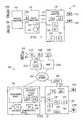
- FIG. 2is a block diagram illustrating another exemplary system 200 for call forwarding.
- system 200includes one or more base stations (BTS) 250 , one or more Wireless Adjunct Internet Platforms (WARP) 252 , a packet network 254 , an integrated communications server 256 , a gateway 258 , and a PBX 260 .
- BTSbase stations
- WARPWireless Adjunct Internet Platforms
- Base station 250is coupled to WARP 252 .
- Base station 250provides bidirectional communication with mobile stations 208 in a specified geographic area over a wireless interface 262 .
- Base station 250also transfers information between mobile station 208 and WARP 252 .
- Base station 250may comprise any hardware, software, firmware, or combination thereof operable to communicate with mobile stations 208 over a wireless interface.
- Base station 250may, for example, comprise one or more transceivers operable to exchange circuit-switched and/or packet-switched information with mobile station 208 .
- Wireless interface 262facilitates communication between mobile station 208 and base station 250 .
- Wireless interface 262may comprise any wireless interface operable to transfer circuit-switched and/or packet-switched information between mobile station 208 and base station 250 .
- Interface 262may, for example, comprise a GSM General Packet Radio Service (GSM/GPRS) interface or a GSM Enhanced Data rates for GSM Evolution (GSM/EDGE) interface.
- GSM/GPRSGeneral Packet Radio Service
- GSM/EDGEGSM Enhanced Data rates for GSM Evolution
- WARP 252is coupled to base station 250 by an interface 264 and to packet network 254 .
- WARP 252facilitates communication between mobile stations 208 and PBX 260 by transporting voice and/or data information between base station 250 and packet network 254 .
- WARP 252communicates with mobile station 208 through base station 250 using a circuit-switched protocol
- WARP 252communicates with packet network 254 using a packet-switched protocol.
- WARP 252also performs an interworking function to translate between the circuit-switched and packet-switched protocols.
- WARP 252may convert between the GSM 04.08 and 08.60 protocols used by mobile station 208 and the ITU-T H.323 protocols used by integrated communications server 256 and gateway 258 .
- WARP 252packetizes information from mobile station 208 into datagrams for transmission over packet network 254
- WARP 252depacketizes information contained in datagrams received over packet network 254 .
- WARP 252may comprise any hardware, software, firmware, or combination thereof operable to facilitate communication between base station 250 and packet network 254 .
- Interface 264is coupled to base station 250 and WARP 252 .
- Interface 264may comprise any suitable interface operable to transfer circuit-switched and/or packet-switched information between base station 250 and WARP 252 .
- Interface 264may, for example, comprise a GSM Abis wireline interface.
- Packet network 254is coupled to WARP 252 , integrated communications server 256 , and gateway 258 . Packet network 254 transports datagrams from one network address in packet network 254 to another network address. In addition, packet network 254 may be coupled to and communicate with external data or voice networks, such as the Internet or a public land mobile network. Packet network 254 may comprise any suitable packet-switched network. Packet network 254 may, for example, comprise a Local Area Network (LAN), a Wide Area Network (WAN), a Metropolitan Area Network (MAN), a portion of a global computer network such as the Internet, or any other communications system or systems at one or more locations.
- LANLocal Area Network
- WANWide Area Network
- MANMetropolitan Area Network
- integrated communications server 256includes a gatekeeper 266 , a Wireless Application Protocol (WAP) server 268 , a subscriber location register (SLR) 270 , and a teleworking server 272 .
- WAPWireless Application Protocol
- SLRsubscriber location register
- FIG. 2illustrates integrated communications server 256 as comprising all four of these components, any or all of these components may be implemented on a separate platform or platforms without departing from the scope of the present invention.
- Gatekeeper 266provides call control services for mobile stations 208 , WARPs 252 , and gateway 258 .
- gatekeeper 266tracks the location of mobile stations 208 , and gatekeeper 266 routes calls for a mobile station 208 to and from the WARP 252 currently serving that mobile station 208 . This allows subscribers using mobile stations 208 to roam between geographic areas covered by different base stations 250 .
- Gatekeeper 266also performs address translation to convert the phone number associated with mobile station 208 to a network address of WARP 252 serving that mobile station 208 .
- gatekeeper 266performs call forwarding functions in system 200 .
- Gatekeeper 266may, for example, instruct PBX 260 to forward calls for a telephone 210 to a mobile station 208 .
- Gatekeeper 266may communicate signaling information to PBX 260 over CTI interface 216 or through gateway 258 .
- Gatekeeper 266may comprise any hardware, software, firmware, or combination thereof operable to provide call control services in system 200 .
- WAP server 268stores subscriber information used to allow mobile stations 208 to execute data-based applications and receive data-based services.
- WAP server 268may, for example, allow mobile stations 208 to send and receive e-mail, access an enterprise's intranet such as packet network 254 , or access the Internet.
- WAP server 268may comprise any suitable hardware, software, firmware, or combination thereof operable to provide WAP functionality to mobile stations 208 .
- Subscriber location register 270stores subscriber management information for mobile stations 208 .
- subscriber location register 270may store general subscriber management information downloaded from a public network when mobile station 208 roams into system 200 .
- Subscriber location register 270also stores each subscriber's extension number, direct dial number, and any other information that is specific to system 200 .
- Subscriber location register 270may comprise any hardware, software, firmware, or combination thereof operable to store subscriber management information.
- Subscriber location register 270may, for example, comprise a SUN workstation with a database.
- Teleworking server 272supports teleworking services in system 200 .
- Teleworking server 272may, for example, allow a user of system 200 to access information and/or communication capabilities of system 200 from remote locations.
- the user of telephone 210may access teleworking server 272 and inform teleworking server 272 of the user's current location.
- Teleworking server 272may allow the user to use a remote telephone and to receive the same features as if the user was using telephone 210 , even if the remote telephone is outside of system 200 .
- Teleworking server 272may comprise any hardware, software, firmware, or combination thereof operable to provide teleworking services in system 200 .
- Gateway 258is coupled to packet network 254 and PBX 260 .
- Gateway 258may also be coupled to a public network, such as a public switched telephone network.
- Gateway 258transfers information between packet network 254 and PBX 260 .
- gateway 258communicates with packet network 254 using a packet-switched protocol and with PBX 260 using a circuit-switched protocol.
- gateway 258also performs an interworking function to translate between the packet-switched and circuit-switched protocols.
- gateway 258converts between the ITU-T H.323 protocols used by WARP 252 and integrated communications server 256 and the circuit-switched protocols used by PBX 260 .
- gateway 258packetizes information into datagrams for transmission over packet network 254 , and gateway 258 depacketizes information contained in datagrams received over packet network 254 .
- Gateway 258may communicate bearer and signaling information to PBX 260 over interface 214 .
- Gateway 258may comprise any hardware, software, firmware, or combination thereof operable to facilitate communication between packet network 254 and PBX 260 .
- PBX 260is coupled to gateway 258 and to one or more telephones 210 .
- PBX 260may also be coupled to one or more public networks, such as a public land mobile network and a public switched telephone network.
- PBX 260transfers information between telephones 210 and/or between gateway 258 and telephones 210 .
- PBX 260may comprise any suitable circuit-switched and/or packet-switched network operable to facilitate communication between telephone 210 and gateway 258 .
- mobile station 208may register with WARP 252 , and WARP 252 informs gatekeeper 266 that mobile station 208 has registered in system 200 .
- Registrationmay occur, for example, when a subscriber turns on mobile station 208 or roams into a geographic area monitored by base station 250 .
- system 200forwards calls for a telephone 210 associated with mobile station 208 to that mobile station 208 .
- System 200may also stop forwarding calls to mobile station 208 when mobile station 208 deregisters with system 200 . Deregistration may occur, for example, when a subscriber turns off mobile station 208 or roams out of the geographic area monitored by base stations 250 in system 200 .
- system 200may route calls for the deregistered mobile station 208 to the telephone 210 associated with mobile station 208 .
- PBX 260includes a call forwarding feature 212 , such as a Call Forward Unconditional feature.
- This feature 212may, for example, be supported by CTI software stored in memory 220 and executed by processor 218 in PBX 260 .
- WARP 252 and/or gatekeeper 266instructs PBX 260 to invoke feature 212 and forward calls for telephone 210 to gateway 258 .
- processor 224 in gatekeeper 266may execute CTI software stored in memory 226 , and processor 224 may instruct processor 218 in PBX 260 to activate or deactivate call forwarding feature 212 .
- Gateway 258receives and forwards the calls to mobile station 208 over packet network 254 , WARP 252 , and base station 250 .
- WARP 252 or gatekeeper 266may instruct PBX 260 to invoke call forwarding feature 212 and forward calls to gateway 258 using the CTI interface 216 or through an administration port (ADMIN) 278 .
- ADMINadministration port
- WARP 252 and/or gatekeeper 266may include a telephone emulator card 274 .
- Card 274appears to PBX 260 as a telephone 210 .
- PBX 260may support a Remote Call Forwarding feature (RCF) 228 , which allows call forwarding feature 212 to be activated and deactivated from another telephone 210 .
- RCFRemote Call Forwarding feature
- WARP 252 or gatekeeper 266instructs PBX 260 to activate or deactivate call forwarding feature 212 using the remote call forwarding feature 228 .
- PBX 260may support a call monitoring feature 230 and a call deflection feature 232 . These features may, for example, be supported by CTI software stored in memory 220 and executed by processor 218 .
- Processor 218 in PBX 260may monitor a telephone 210 using monitoring feature 230 and wait for an alert event, which indicates that an incoming call for telephone 210 exists.
- processor 224determines if the mobile station 208 associated with telephone 210 is registered in system 200 . If the mobile station 208 is registered, processor 224 instructs processor 218 in PBX 260 to deflect the incoming call to gateway 258 over interface 214 using deflection feature 232 .
- WARP 252 or gatekeeper 266may instruct teleworking server 272 to treat mobile station 208 as a remote location for telephone 210 .
- Teleworking server 272then instructs PBX 260 to forward calls for telephone 210 to mobile station 208 using remote call forwarding feature 228 .
- FIG. 2illustrates one embodiment of system 200
- various changesmay be made to system 200 without departing from the scope of the present invention.
- any number of base stations 250may be coupled to each WARP 252
- any number of WARPs 252may be coupled to packet network 254 .
- FIG. 2illustrates a PBX 260 coupled to gateway 258
- other telephone systemsmay be coupled to gateway 258 , such as a Key System, a central office switch, a wireless telephone switch, a packet-based soft switch, or any other suitable circuit-switched and/or packet-switched system.
- gatekeeper 266 and gateway 258are illustrated as separate entities, both may be implemented in an integrated platform.
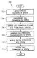
- FIG. 3is a flow diagram illustrating an exemplary method 300 for call forwarding in a communication system.
- System 100directs calls to a telephone 110 in a telephone subsystem 106 at step 302 . This may include, for example, telephone subsystem 106 receiving a call from a public network, another telephone 110 in telephone subsystem 106 , or a mobile station 108 .
- System 100detects a mobile station 108 associated with a telephone 110 at step 304 . This may include, for example, mobile station 108 registering with wireless subsystem 102 and/or packet subsystem 104 , such as by communicating a registration signal to wireless subsystem 102 .
- System 100forwards calls for the telephone 110 in the telephone subsystem 106 to the mobile station 108 at step 306 .
- Thismay include, for example, wireless subsystem 102 and/or packet subsystem 104 instructing telephone subsystem 106 to forward calls for telephone 110 to mobile station 108 .
- System 100loses contact with mobile station 108 at step 308 . This may include, for example, mobile station 108 deregistering from system 100 , such as when a subscriber turns off mobile station 108 or roams outside the geographic area covered by wireless subsystem 102 .
- System 100stops forwarding calls for telephone 110 to mobile station 108 at step 310 . This may include, for example, wireless subsystem 102 and/or packet subsystem 104 clearing the call forwarding feature in telephone subsystem 106 .
- method 300may be used with any suitable communication system.
- Method 300may be used, for example, in a system having a packet subsystem 104 and a telephone subsystem 106 , without a wireless subsystem 102 .
- method 300may forward calls directed at telephone 110 to a packet-based client coupled to packet subsystem 104 .
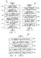
- FIG. 4is a flow diagram illustrating an exemplary method 400 for forwarding calls for a telephone to a mobile station.
- a mobile station 208registers with system 200 at step 402 . This may include, for example, a subscriber turning on mobile station 208 or roaming into the geographic area covered by system 200 . This may also include mobile station 208 communicating a registration signal to base station 250 , which communicates the signal to WARP 252 . WARP 252 may then inform gatekeeper 266 of the registration.
- System 200instructs PBX 260 to forward telephone calls for a telephone 210 associated with mobile station 208 to mobile station 208 at step 404 .
- PBX 260forwards calls for telephone 210 to mobile station 208 at step 406 .
- Thismay include, for example, PBX 260 receiving a telephone call for a telephone 210 and forwarding the call to gateway 258 .
- FIG. 5is a flow diagram illustrating another exemplary method 500 for forwarding calls for a telephone 210 to a mobile station 208 .
- a mobile station 208registers with system 200 at step 502 . This may include, for example, a subscriber turning on mobile station 208 or roaming into range of a base station 250 in system 200 . This may also include mobile station 208 communicating a registration message to base station 250 , base station 250 forwarding the information to WARP 252 , and WARP 252 informing gatekeeper 266 of the registration.
- System 200instructs PBX 260 to monitor a telephone 210 at step 504 .
- PBX 260listens for an alert event at step 506 .
- An alert eventis generated when an incoming call for a telephone 210 has been received by PBX 260 .
- PBX 260detects an alert at step 508 . This indicates that someone has placed an incoming call to telephone 210 , and an alert signal has been communicated to telephone 210 to cause telephone 210 to ring.
- PBX 260deflects the incoming call from the monitored telephone 210 to mobile station 208 at step 510 . This may include, for example, processor 218 in PBX 260 redirecting the incoming call using deflection feature 232 to gateway 258 , which forwards the incoming call to mobile station 208 .
- FIG. 6is a flow diagram illustrating yet another exemplary method 600 for forwarding calls for a telephone 210 to a mobile station 208 .
- Mobile station 208registers with system 200 at step 602 . This may include, for example, a subscriber turning on mobile station 208 or roaming into system 200 .
- Teleworking server 272is instructed to treat mobile station 208 as a remote location for a telephone 210 at step 604 . This may include, for example, mobile station 208 , WARP 252 , and/or gatekeeper 266 communicating the instructions to teleworking server 272 .
- Teleworking server 272instructs PBX 260 to forward calls for telephone 210 to mobile station 208 at step 606 .
- Thismay include, for example, teleworking server 272 instructing PBX 260 to forward the calls to gateway 258 using remote call forwarding feature 228 and call forwarding feature 212 .
- PBX 260forwards calls for telephone 210 to mobile station 208 at step 608 .
- Thismay include, for example, PBX 260 forwarding the calls for telephone 210 to gateway 258 , which forwards the calls to mobile station 208 .
- FIG. 7is a flow diagram illustrating an exemplary method 700 for synchronizing call forwarding in a communication system.
- a mobile station 208registers with system 200 at step 702 . This may include, for example, mobile station 208 being turned on or roaming into system 200 .
- System 200synchronizes the call forwarding destinations in the different components of system 200 at step 704 . If neither mobile station 208 nor telephone 210 is forwarded to a specific destination, this may include system 200 forwarding telephone 210 to mobile station 208 . If one of mobile station 208 or telephone 210 is forwarded to a specific destination, this may include ensuring that both mobile station 208 and telephone 210 are forwarded to the same destination. If mobile station 208 and telephone 210 are forwarded to different destinations, this may include forwarding one of the devices 208 , 210 to the destination of the other 210 , 208 .
- a change to the call forwarding feature in either telephone 210 or mobile station 208is made at step 706 .
- Thismay include, for example, a subscriber forwarding mobile station 208 or telephone 210 to a new destination.
- System 200maintains call forwarding synchronization at step 708 . This may include, for example, ensuring either that mobile station 208 and telephone 210 are forwarded to the same destination, telephone 210 is forwarded to mobile station 208 , or mobile station 208 is forwarded to telephone 210 .
- Mobile station 208deregisters with system 200 at step 710 . This may include, for example, a subscriber turning off mobile station 208 or roaming outside of system 200 .
- System 200restores the call forwarding in system 200 at step 712 .
- method 700may be used with any suitable communication system.
- Method 700may be used, for example, in a system having a packet subsystem 104 and a telephone subsystem 106 , without a wireless subsystem 102 .
- method 700may synchronize call forwarding for a telephone 110 and a packet-based client coupled to packet subsystem 104 .
- Method 700could also be used in a system having a wireless subsystem 102 and a telephone subsystem 106 , without a packet subsystem 104 .
- FIG. 8is a flow diagram illustrating an exemplary method 800 for establishing a call forwarding destination for a mobile station 208 .
- Telephone 210is forwarded to a specific destination, called “location X,” at step 802 .
- Thismay include, for example, a user of telephone 210 manually forwarding telephone 210 to the specific destination.
- Mobile station 208registers with system 200 at step 804 .
- System 200forwards calls for mobile station 208 to the specific destination at step 806 .
- Thismay include, for example, gatekeeper 266 and/or WARP 252 receiving the specific destination from PBX 260 .
- Thismay also include WARP 252 and/or gatekeeper 266 routing datagrams destined for mobile station 208 to the forwarded location. This helps to synchronize call forwarding in system 200 by ensuring that calls for the subscriber are routed to the same location, whether the incoming calls are directed at mobile station 208 or telephone 210 .
- the subscriberturns off the call forwarding feature for mobile station 208 at step 808 .
- Thismay include the subscriber manually entering a code on mobile station 208 to deactivate the call forwarding.
- Thismay also include WARP 252 and/or gatekeeper 266 receiving the instruction to deactivate call forwarding for the mobile station 208 .
- System 200sets the call forwarding for the telephone 210 to the mobile station 208 at step 810 .
- Thismay include, for example, WARP 252 and/or gatekeeper 266 instructing PBX 260 to forward calls for telephone 210 to mobile station 208 .
- Thisalso helps to synchronize call forwarding in system 200 by ensuring that calls for the subscriber are routed to the mobile station 208 .
- FIG. 9is a flow diagram illustrating an exemplary method 900 for establishing a call forwarding destination for a telephone 210 associated with a mobile station 208 .
- Method 900begins at step 902 , where the call forwarding feature of a mobile station 208 is turned off, or not set to a specified location.
- Mobile station 208registers with system 200 at step 904 , and system 200 forwards calls for the associated telephone 210 to the mobile station 208 at step 906 . This helps to ensure call forward synchronization in system 200 by directing calls for the subscriber to the subscriber's mobile station 208 .
- the subscriberactivates the call forwarding feature and forwards calls for mobile station 208 to a specific destination, labeled “location Y,” at step 908 .
- Thismay include, for example, the subscriber manually entering a code on mobile station 208 to forward mobile station 208 to the specific destination.
- Thismay also include WARP 252 and/or gatekeeper 266 receiving the new destination for mobile station 208 .
- System 200forwards calls for the associated telephone 210 to the same destination at step 910 .
- Thismay include, for example, WARP 252 and/or gatekeeper 266 instructing PBX 260 to forward calls for telephone 210 to the new destination. This helps to synchronize call forwarding in system 200 by ensuring that calls for the subscriber are forwarded to the same destination, whether the calls are directed at the subscriber's mobile station 208 or telephone 210 .
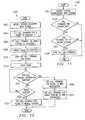
- FIG. 10is a flow diagram illustrating another exemplary method 1000 for establishing a call forwarding destination for a telephone 210 associated with a mobile station 208 .
- Mobile station 208registers with system 200 at step 1002 .
- a subscriberforwards calls for a telephone 210 associated with mobile station 208 to a specific destination, called “location Z,” at step 1004 .
- System 200also activates the call forwarding feature for mobile station 208 and forwards calls for mobile station 208 to the same specific destination at step 1006 . Calls for the subscriber are forwarded to the destination at step 1008 , whether the calls are directed at the mobile station 208 or the telephone 210 .
- Call forwardingis deactivated for the telephone 210 at step 1010 , such as by manually deactivating the call forwarding feature.
- System 200starts a timer at step 1012 .
- Gatekeeper 266 and/or WARP 252may set the timer to any suitable duration, such as fifteen seconds.
- System 200determines if another call forwarding destination for telephone 210 is entered at step 1014 . This may include, for example, WARP 252 and/or gatekeeper 266 determining if another destination has been entered. If another destination is entered before the timer elapses, system 200 sets the call forwarding destination for the telephone 210 to the new destination at step 1016 . To maintain synchronization, system 200 also forwards mobile station 208 to the new destination at step 1018 .
- system 200checks whether the timer has elapsed at step 1020 . If the timer has not elapsed, system 200 returns to step 1014 to await a new call forwarding destination. When the timer elapses, system 200 sets the call forwarding destination for telephone 210 to mobile station 208 . System 200 maintains call forwarding synchronization by ensuring that calls for the subscriber are routed to the mobile station 208 .
- FIG. 11is a flow diagram illustrating an exemplary method 1100 for establishing a call forwarding destination for a telephone 210 associated with a deregistered mobile station 208 .
- a mobile station 208deregisters with system 200 at step 1102 . This may include, for example, a subscriber turning off mobile station 208 or roaming outside of system 200 .
- System 200determines if telephone 210 is forwarded at step 1104 . This may include, for example, WARP 252 and/or gatekeeper 266 determining if the call forwarding feature 212 for telephone 210 has been activated. If telephone 210 is not forwarded, method 1100 ends. Call forwarding in system 200 is synchronized because telephone 210 is not forwarded to a deregistered mobile station 208 .
- system 200determines if telephone 210 is forwarded to the mobile station 208 at step 1106 . This may include, for example, WARP 252 and/or gatekeeper 266 determining if telephone 210 has been forwarded to gateway 258 . If not, method 1100 ends. Call forwarding in system 200 is synchronized because telephone 210 is not forwarded to a deregistered mobile station 208 . If telephone 210 is forwarded to the mobile station 208 at step 1106 , system 200 deactivates the call forwarding for telephone 210 at step 1108 . Because telephone 210 is forwarded to a deregistered mobile station 208 , system 200 deactivates call forwarding for telephone 210 to maintain synchronization in system 200 .
- FIG. 12is a block diagram illustrating yet another exemplary system 1200 for call forwarding.
- system 1200includes a base station 1250 , a central office 1280 , a cable box 1282 , and a converter box 1284 .
- Other embodiments of system 1200may be used without departing from the scope of the present invention.
- Central office 1280is coupled to telephones 1210 and cable box 1282 .
- Central office 1280facilitates communication in system 1200 , such as between two telephones 1210 or between a telephone 1210 and cable box 1282 .
- Central office 1280may comprise any suitable circuit-switched and/or packet-switched system, such as one or more Class 5 switches.
- Cable box 1282is coupled to central office 1280 and converter box 1284 .
- Cable box 1282facilitates communication between central office 1280 and converter box 1284 .
- cable box 1282communicates with central office 1280 using a first protocol and with converter box 1284 using a second protocol.
- cable box 1282may communicate with converter box 1284 using a packet over cable protocol, and cable box 1282 may communicate with central office 1280 using a Bellcore GR-303 interface, a V5.2 interface, or a V5.3 interface.
- cable box 1282may convert and packetize information from central office 1280 for communication to converter box 1284 .
- Cable box 1282may also convert and depacketize information from converter box 1284 for communication to central office 1280 .
- Cable box 1282may comprise any hardware, software, firmware, or combination thereof operable to facilitate communication of voice information between central office 1280 and converter box 1284 .
- Converter box 1284is coupled to cable box 1282 , one or more devices 1286 , and base station 1250 .
- Converter box 1284is operable to receive information from cable box 1282 and to communicate the information to one or more devices 1286 or base station 1250 .
- converter box 1284may receive audio and video information, voice information, and/or data from cable box 1282 .
- Converter box 1284may communicate the audio and video information to a television 1286 a , the voice information to a telephone 1286 b or base station 1250 , and the data to a computing device 1286 c.
- Converter box 1284may also receive information from devices 1286 and/or base station 1250 , such as voice information from device 1286 b and/or base station 1250 .
- Converter box 1284is operable to communicate the information to central office 1280 through cable box 1282 .
- a signalmay be sent through converter box 1284 and cable box 1282 to central office 1280 .
- a call forwarding feature 1212 or other feature in central office 1280may cause calls directed at a telephone 1210 to be forwarded to mobile station 1208 .
- call forwarding feature 1212 or another feature of central office 1280may be used to forward calls for telephone 1286 b to mobile station 1208 .
- a signalmay be sent to central office 1280 instructing central office 1280 to stop forwarding calls to mobile station 1208 .
- devices 1286may be located in a residence 1292 , such as a house or apartment.
- television 1286 amay receive cable television services
- phone 1286 bmay receive voice over cable services
- computing device 1286 cmay receive cable modem services through converter box 1284 .
- a base station 1250such as an antenna with a range of 300 feet, may be installed in residence 1292 .
- central office 1280may be instructed to forward calls for a telephone 1210 to mobile station 1208 .
- Telephone 1210could, for example, represent a desk phone at the office of the subscriber using mobile station 1208 , and calls directed to the subscriber's office would be forwarded to mobile station 1208 . Also, because calls for telephone 1286 b may be routed through central office 1280 , central office 1280 may forward calls for telephone 1286 b to mobile station 1208 . This may allow, for example, all calls for the subscriber to be forwarded to mobile station 1208 , whether the calls are directed at telephone 1210 , telephone 1286 b in residence 1292 , or mobile station 1208 .
- FIG. 12illustrates one embodiment of system 1200
- system 1200may include some or none of devices 1286 .
- converter box 1284may not possess the ability to directly communicate information to and receive information from base station 1250
- a WARPmay be coupled between base station 1250 and converter box 1284 to facilitate communication.
- FIG. 13is a block diagram illustrating still another exemplary system 1300 for call forwarding.
- system 1300includes a voice over packet subsystem 1304 and a telephone subsystem 1306 .
- Other embodiments of system 1300may be used without departing from the scope of the present invention.
- telephone subsystem 1306may be the same or similar to telephone subsystem 106 of FIG. 1 and/or PBX 260 of FIG. 2 .
- telephone subsystem 1306may include a call forwarding feature 1312 , a remote call forwarding feature 1328 , a call monitoring feature 1330 , a call deflection feature 1332 , a processor 1318 , and a memory 1320 .
- Telephone subsystem 1306may also communicate with one or more telephones 1310 .
- packet subsystem 1304includes a voice over packet client 1350 , a gateway 1358 , and a gatekeeper 1366 .
- Client 1350is coupled to gatekeeper 1366 and gateway 1358 .
- Client 1350facilitates the communication of packet voice information to telephone subsystem 1306 .
- Client 1350may, for example, receive voice information, packetize the information, and communicate the packets to gateway 1358 .
- Client 1350may also receive packets of voice information from gateway 1358 and extract the information.
- client 1350may operate in an active state or a non-active state. The active state indicates that calls directed at a telephone 1310 associated with client 1350 should be forwarded to client 1350 .
- the non-active stateindicates that calls directed at client 1350 should be forwarded to the telephone 1310 associated with client 1350 .
- Client 1350may comprise any hardware, software, firmware, or combination thereof operable to provide packet voice services in system 1300 .
- Client 1350may, for example, comprise a voice over packet telephone, a computing device, or a gateway operable to communicate with another communications system.
- client 1350comprises a Wireless Adjunct Internet Platform operable to facilitate communication between packet subsystem 1304 and a wireless system.
- Gateway 1358 and gatekeeper 1366may be the same or similar to gateway 258 and gatekeeper 266 , respectively, of FIG. 2 .
- gatekeeper 1366is coupled to client 1350 , gateway 1358 , and telephone subsystem 1306 .
- Gatekeeper 1366is operable to communicate signaling information to client 1350 , gateway 1358 , and telephone subsystem 1306 .
- Gatekeeper 1366may communicate the signaling information to telephone subsystem 1306 over CTI interface 1316 or through gateway 1358 .
- Gatekeeper 1366is also operable to instruct telephone subsystem 1306 to forward a call for a telephone 1310 to a client 1350 when client 1350 is in the active state.
- Gatekeeper 1366is further operable to instruct gateway 1358 to forward a call for a client 1350 to a telephone 1310 when client 1350 is in the non-active state.
- Gatekeeper 1366may comprise any hardware, software, firmware, or combination thereof operable to instruct telephone subsystem 1306 and/or gateway 1358 to forward calls in system 1300 .
- Gateway 1358is coupled to client 1350 , gatekeeper 1366 , and telephone subsystem 1306 .
- Gateway 1358facilitates communication between client 1350 and telephone subsystem 1306 .
- Gateway 1358may, for example, receive packets containing voice information from client 1350 , extract the voice information, and communicate the information to telephone subsystem 1306 .
- Gateway 1358may also receive voice information from telephone system 1306 , packetize the information, and communicate the packets to client 1350 .
- gateway 1358may facilitate the communication of signaling information between gatekeeper 1366 and telephone subsystem 1306 over interface 1314 .
- Gateway 1358may comprise any hardware, software, firmware, or combination thereof operable to facilitate communication between client 1350 and telephone subsystem 1306 .
- client 1350when client 1350 is activated, client 1350 registers with gatekeeper 1366 .
- Gatekeeper 1366instructs telephone subsystem 1306 to forward calls directed at the telephone 1310 associated with client 1350 to gateway 1358 .
- Gatekeeper 1366may also instruct gateway 1358 not to forward calls for client 1350 to telephone subsystem 1306 .
- telephone subsystem 1306receives a call directed at client 1350 or the associated telephone 1310 , telephone subsystem 1306 forwards the call to gateway 1358 , which communicates the call to client 1350 . If a second client 1350 attempts to call the first client 1350 , the call may be routed through packet subsystem 1304 without being routed through telephone subsystem 1306 .
- client 1350When client 1350 is deactivated, or enters the non-active state, client 1350 deregisters with gatekeeper 1366 .
- Gatekeeper 1366instructs telephone subsystem 1306 to stop forwarding calls to client 1350 , and gatekeeper 1366 instructs gateway 1358 to forward calls for client 1350 to the associated telephone 1310 . If packet subsystem 1304 receives a call for the deactivated client 1350 , such as from another client 1350 , gatekeeper 1366 routes the call through telephone subsystem 1306 to the telephone 1310 associated with the deactivated client 1350 .
- client 1350comprises a gateway to a wireless network, such as a Wireless Adjunct Internet Platform.
- client 1350may operate in an active state when a mobile station is registered with the wireless network.
- client 1350may operate in a non-active state when no mobile stations are registered with the wireless network.
- Gatekeeper 1366may use any suitable method for instructing telephone subsystem 1306 to forward calls for a telephone 1310 to gateway 1358 .
- Gatekeeper 1366may, for example, use method 1400 illustrated in FIG. 14 , or the methods illustrated in FIGS. 3-6 where client 1350 takes the place of the mobile station in methods 300 - 600 .
- system 1300may use any suitable method for maintaining call forwarding synchronization. This may include, for example, system 1300 using the methods illustrated in FIGS. 7-11 , with client 1350 taking the place of the mobile station in methods 700 - 1100 .
- FIG. 13illustrates one embodiment of system 1300
- various changesmay be made without departing from the scope of the present invention.
- any number and/or types of clients 1350may be coupled to a gatekeeper 1366 and a gateway 1358 .
- any number of gatekeepers 1366 and/or gateways 1358may be coupled to telephone subsystem 1306 .
- Other changesmay be made to system 1300 without departing from the scope of the present invention.
- FIG. 14is a flow diagram illustrating another exemplary method 1400 for call forwarding in a communications system.
- System 1300determines the state of a client 1350 at step 1402 . This may include, for example, gatekeeper 1366 determining if the client 1350 is registered with gatekeeper 1366 . Registered clients 1350 may be in an active state, while unregistered clients 1350 are in the non-active state.
- System 1300determines if client 1350 is in an active state at step 1404 . If client 1350 is in an active state, system 1300 instructs telephone subsystem 1306 to forward calls directed at a telephone 1310 to the associated client 1350 at step 1406 .
- system 1300may route calls for a user of client 1350 to client 1350 , whether the calls are directed at client 1350 or telephone 1310 .
- system 1300instructs gateway 1358 to forward calls for client 1350 to telephone 1310 at step 1408 .
- Thismay include, for example, gatekeeper 1366 instructing gateway 1358 to forward calls for client 1350 to telephone subsystem 1306 .
- system 1300routes calls for the user of client 1350 to the associated telephone 1310 , whether the calls are directed at client 1350 or telephone 1310 .
Landscapes
- Engineering & Computer Science (AREA)
- Signal Processing (AREA)
- Mobile Radio Communication Systems (AREA)
Abstract
Description
Claims (38)
Priority Applications (2)
| Application Number | Priority Date | Filing Date | Title |
|---|---|---|---|
| US09/781,927US6950650B2 (en) | 2001-02-12 | 2001-02-12 | System and method for call forwarding synchronization in a communication system |
| PCT/US2001/049254WO2002065743A2 (en) | 2001-02-12 | 2001-12-19 | System and method for call forwarding synchronization in a communication system |
Applications Claiming Priority (1)
| Application Number | Priority Date | Filing Date | Title |
|---|---|---|---|
| US09/781,927US6950650B2 (en) | 2001-02-12 | 2001-02-12 | System and method for call forwarding synchronization in a communication system |
Publications (2)
| Publication Number | Publication Date |
|---|---|
| US20020115432A1 US20020115432A1 (en) | 2002-08-22 |
| US6950650B2true US6950650B2 (en) | 2005-09-27 |
Family
ID=25124402
Family Applications (1)
| Application Number | Title | Priority Date | Filing Date |
|---|---|---|---|
| US09/781,927Expired - LifetimeUS6950650B2 (en) | 2001-02-12 | 2001-02-12 | System and method for call forwarding synchronization in a communication system |
Country Status (2)
| Country | Link |
|---|---|
| US (1) | US6950650B2 (en) |
| WO (1) | WO2002065743A2 (en) |
Cited By (24)
| Publication number | Priority date | Publication date | Assignee | Title |
|---|---|---|---|---|
| US20010026545A1 (en)* | 2000-03-28 | 2001-10-04 | Fujitsu Limited | Method and apparatus for registering IP terminal device in line-switching exchanger |
| US20030008642A1 (en)* | 2001-07-06 | 2003-01-09 | Siemens Information And Communication Networks, Inc. | Self-learning intelligent call routing gatekeeper |
| US20040234060A1 (en)* | 2003-03-31 | 2004-11-25 | Nokia Corporation | Method and system for deactivating a service account |
| US20050036592A1 (en)* | 2001-12-19 | 2005-02-17 | Holt Scott C. | Systems and methods for monitoring network-based voice messaging systems |
| US20050204025A1 (en)* | 2004-03-10 | 2005-09-15 | Ixi Mobile (R&D) Ltd. | Telephony event management system and method in a communications network |
| US20070076691A1 (en)* | 2005-09-30 | 2007-04-05 | Varney Douglas W | Method and apparatus for allowing peering relationships between telecommunications networks |
| US20080152118A1 (en)* | 2006-12-22 | 2008-06-26 | Embarq Holdings Company, Llc. | System and method for virtual wireless roaming |
| US7962142B2 (en) | 2003-01-31 | 2011-06-14 | Qualcomm Incorporated | Methods and apparatus for the utilization of core based nodes for state transfer |
| US8463257B1 (en) | 2010-01-14 | 2013-06-11 | Michael Shaoul | System for redirecting cellular phone calls to conventional landline handsets |
| US8509799B2 (en) | 2005-09-19 | 2013-08-13 | Qualcomm Incorporated | Provision of QoS treatment based upon multiple requests |
| US8588777B2 (en) | 1998-09-22 | 2013-11-19 | Qualcomm Incorporated | Method and apparatus for robust handoff in wireless communication systems |
| US8615241B2 (en) | 2010-04-09 | 2013-12-24 | Qualcomm Incorporated | Methods and apparatus for facilitating robust forward handover in long term evolution (LTE) communication systems |
| US8625537B1 (en)* | 2009-03-10 | 2014-01-07 | Sprint Communications Company L.P. | Controlling mobile-device roaming |
| US8830818B2 (en) | 2007-06-07 | 2014-09-09 | Qualcomm Incorporated | Forward handover under radio link failure |
| US8886180B2 (en) | 2003-01-31 | 2014-11-11 | Qualcomm Incorporated | Enhanced techniques for using core based nodes for state transfer |
| US8982778B2 (en) | 2005-09-19 | 2015-03-17 | Qualcomm Incorporated | Packet routing in a wireless communications environment |
| US8983468B2 (en) | 2005-12-22 | 2015-03-17 | Qualcomm Incorporated | Communications methods and apparatus using physical attachment point identifiers |
| US8982835B2 (en) | 2005-09-19 | 2015-03-17 | Qualcomm Incorporated | Provision of a move indication to a resource requester |
| US9066344B2 (en) | 2005-09-19 | 2015-06-23 | Qualcomm Incorporated | State synchronization of access routers |
| US9078084B2 (en) | 2005-12-22 | 2015-07-07 | Qualcomm Incorporated | Method and apparatus for end node assisted neighbor discovery |
| US9083355B2 (en) | 2006-02-24 | 2015-07-14 | Qualcomm Incorporated | Method and apparatus for end node assisted neighbor discovery |
| US9094173B2 (en) | 2007-06-25 | 2015-07-28 | Qualcomm Incorporated | Recovery from handoff error due to false detection of handoff completion signal at access terminal |
| US9155008B2 (en) | 2007-03-26 | 2015-10-06 | Qualcomm Incorporated | Apparatus and method of performing a handoff in a communication network |
| US9736752B2 (en) | 2005-12-22 | 2017-08-15 | Qualcomm Incorporated | Communications methods and apparatus using physical attachment point identifiers which support dual communications links |
Families Citing this family (9)
| Publication number | Priority date | Publication date | Assignee | Title |
|---|---|---|---|---|
| US6967947B1 (en)* | 2001-03-29 | 2005-11-22 | At&T Corp. | Method and system for providing controllable enhanced call service features at mobile locations |
| US20030032428A1 (en)* | 2001-08-09 | 2003-02-13 | Yinjun Zhu | System, method, and apparatus for gatekeeper networking in communication system |
| US7729339B2 (en)* | 2003-07-31 | 2010-06-01 | Alcatel-Lucent Usa Inc. | Audio watermarking for call identification in a telecommunications network |
| US7219201B2 (en)* | 2003-09-17 | 2007-05-15 | Hitachi, Ltd. | Remote storage disk control device and method for controlling the same |
| JP4598387B2 (en)* | 2003-09-17 | 2010-12-15 | 株式会社日立製作所 | Storage system |
| DE102004027126A1 (en)* | 2004-06-03 | 2005-12-29 | Siemens Ag | Method and computer for configuring a communication node |
| JP4346519B2 (en)* | 2004-07-13 | 2009-10-21 | 株式会社東芝 | Telephone system, communication control method thereof, and application control apparatus |
| US8145243B2 (en)* | 2005-11-08 | 2012-03-27 | Intel Corporation | Techniques for location management and paging in a communication system |
| DE102006013218A1 (en)* | 2006-03-22 | 2007-10-04 | Siemens Ag | A method for locating and placing a mobile voice-over-IP subscriber in a local area to an emergency call center |
Citations (68)
| Publication number | Priority date | Publication date | Assignee | Title |
|---|---|---|---|---|
| EP0588510A1 (en) | 1992-08-31 | 1994-03-23 | AT&T Corp. | Call routing scheme with verification of called party presence |
| US5506887A (en) | 1992-03-05 | 1996-04-09 | Bell Atlantic Network Services, Inc. | Personal communications service using wireline/wireless integration |
| US5537610A (en) | 1990-06-18 | 1996-07-16 | Northern Telecom Limited | Mobile communication having mobile subscribers, PCN network, PBX and a local exchange |
| US5579384A (en) | 1995-02-17 | 1996-11-26 | Bellsouth Corporation | Telecommunications network service central management system interfacing with protocol specific regional stations providing services to subscribers |
| US5602843A (en) | 1994-07-21 | 1997-02-11 | Mitel Corporation | Integrated wired and wireless telecommunications system |
| US5604737A (en) | 1993-12-15 | 1997-02-18 | Hitachi, Ltd. | Voice communication system and voice communication method |
| US5610974A (en) | 1994-04-05 | 1997-03-11 | Telefonaktiebolaget Lm Ericsson | Method and arrangement for handling a mobile telephone subscriber administered in different mobile telephone networks with a common call number |
| US5613100A (en) | 1989-09-12 | 1997-03-18 | Nec Corporation | Computer system having an open systems interconnection (OSI) management system for an information conversion for management of non-open systems |
| US5629974A (en) | 1995-11-16 | 1997-05-13 | Nokia Telecommunications Oy | Communication system providing mobility management internetworking between a C-interface radio system and an overlay mobile radio network |
| US5636218A (en) | 1994-12-07 | 1997-06-03 | International Business Machines Corporation | Gateway system that relays data via a PBX to a computer connected to a pots and a computer connected to an extension telephone and a lanand a method for controlling same |
| US5652787A (en) | 1993-04-17 | 1997-07-29 | Northern Telecom Limited | Management system for public and private switched networks |
| US5655001A (en) | 1992-09-25 | 1997-08-05 | Lucent Technologies Inc. | Wireless telecommunication system using protocol conversion for signaling between base stations and land based switches |
| EP0793375A2 (en) | 1996-02-28 | 1997-09-03 | AT&T Corp. | Automatic cellular telephone registration for universal telephone number service |
| US5673308A (en)* | 1994-10-12 | 1997-09-30 | Bell Atlantic Network Services, Inc. | Personal phone number system |
| US5713073A (en) | 1994-08-23 | 1998-01-27 | Nokia Telecommunications Oy | Location updating in a mobile communication system |
| US5726979A (en) | 1996-02-22 | 1998-03-10 | Mci Corporation | Network management system |
| US5729599A (en)* | 1996-06-11 | 1998-03-17 | U S West, Inc. | Method and system of forwarding calls in a remote access call forwarding service of a telephone system |
| US5734699A (en) | 1995-05-04 | 1998-03-31 | Interwave Communications International, Ltd. | Cellular private branch exchanges |
| US5740374A (en) | 1994-07-11 | 1998-04-14 | Koninklijke Ptt Nederland N.V. | System for transferring messages via different sub-networks by converting control codes into reference code compatible with a reference protocol and encapsulating the code with the message |
| US5742596A (en) | 1995-11-12 | 1998-04-21 | Phonet Communication Ltd. | Network based distributed PBX system |
| US5742905A (en) | 1994-09-19 | 1998-04-21 | Bell Communications Research, Inc. | Personal communications internetworking |
| EP0841798A2 (en) | 1996-11-07 | 1998-05-13 | Nokia Mobile Phones Ltd. | Call diversion |
| US5754539A (en) | 1995-04-13 | 1998-05-19 | Alcatel N.V. | Local area network for use in office communications and a circuit arrangement therefor |
| US5764955A (en) | 1995-10-19 | 1998-06-09 | Oasys Group, Inc. | Gateway for using legacy telecommunications network element equipment with a common management information protocol |
| US5771275A (en) | 1996-12-17 | 1998-06-23 | Telefonaktiebolaget Lm Ericsson | Use of ISDN to provide wireless office environment connection to the public land mobile network |
| US5793762A (en) | 1994-04-12 | 1998-08-11 | U S West Technologies, Inc. | System and method for providing packet data and voice services to mobile subscribers |
| US5794009A (en) | 1996-05-09 | 1998-08-11 | Eagle Research Corp. | Multiple protocol management system |
| US5809028A (en) | 1995-06-02 | 1998-09-15 | Dsc Communications Corporation | Protocol converter for a wireless telecommunications system |
| US5818824A (en) | 1995-05-04 | 1998-10-06 | Interwave Communications International, Ltd. | Private multiplexing cellular network |
| US5822569A (en) | 1994-02-28 | 1998-10-13 | British Telecommunications Public Limited Company | Data storage device |
| US5839067A (en) | 1995-01-10 | 1998-11-17 | Telefonaktiebolaget Lm Ericsson | Corporate communication system |
| US5862134A (en) | 1995-12-29 | 1999-01-19 | Gte Laboratories Incorporated | Single-wiring network for integrated voice and data communications |
| US5862481A (en) | 1996-04-08 | 1999-01-19 | Northern Telecom Limited | Inter-technology roaming proxy |
| US5873031A (en) | 1994-01-03 | 1999-02-16 | Lucent Technologies Inc. | Implementation of wireless terminal roaming capability via a wired terminal registration feature |
| US5873033A (en) | 1995-02-06 | 1999-02-16 | Telia Ab | Method and arrangement for transfer between a cordless telecommunication system and a cellular mobile telecommunication system |
| US5878347A (en) | 1996-03-26 | 1999-03-02 | Ericsson, Inc. | Routing a data signal to a mobile station within a telecommunications network |
| US5887256A (en) | 1995-05-04 | 1999-03-23 | Interwave Communications International, Ltd. | Hybrid cellular communication apparatus and method |
| US5892950A (en) | 1996-08-09 | 1999-04-06 | Sun Microsystems, Inc. | Interface for telecommunications network management |
| US5898931A (en) | 1995-08-09 | 1999-04-27 | Hewlett-Packard Company | Base station for a telecommunications system |
| US5901352A (en) | 1997-02-20 | 1999-05-04 | St-Pierre; Sylvain | System for controlling multiple networks and associated services |
| US5901359A (en) | 1997-01-03 | 1999-05-04 | U S West, Inc. | System and method for a wireline-wireless network interface |
| US5905789A (en)* | 1996-10-07 | 1999-05-18 | Northern Telecom Limited | Call-forwarding system using adaptive model of user behavior |
| US5913166A (en) | 1995-12-29 | 1999-06-15 | Lucent Technologies Inc. | Arrangement for providing a call hand-off for a mobile station from a land-line supported private base station to a cellular base station operating in a cellular system |
| US5924030A (en) | 1995-09-29 | 1999-07-13 | Nokia Mobile Phones Limited | Cellular extension of a fixed communications network |
| US5943619A (en) | 1997-04-29 | 1999-08-24 | Ericsson Inc. | Shared interworking of subscriber features within mobile telecommunications networks |
| US5949775A (en) | 1995-09-29 | 1999-09-07 | Nokia Mobile Phones Ltd. | Office communication system |
| US5953322A (en)* | 1997-01-31 | 1999-09-14 | Qualcomm Incorporated | Cellular internet telephone |
| US5953651A (en) | 1995-05-04 | 1999-09-14 | Interwave Communications International, Ltd. | Cellular adjunct to a public wired network |
| US5956331A (en) | 1995-09-29 | 1999-09-21 | Nokia Mobile Phones Limited | Integrated radio communication system |
| US5960004A (en) | 1991-06-28 | 1999-09-28 | Telefonaktiebolaget L M Ericsson (Publ) | Modular application software for telecommunications exchanges for providing all end user services traffic handling and charging requirements of an applications type |
| US5960176A (en) | 1995-09-07 | 1999-09-28 | Kokusai Denshin Denwa Co., Ltd. | Apparatus for management of SNMP/OSI gateways |
| US5960344A (en) | 1993-12-20 | 1999-09-28 | Norand Corporation | Local area network having multiple channel wireless access |
| US5978672A (en) | 1996-09-27 | 1999-11-02 | Global Mobility Systems, Inc. | Mobility extended telephone application programming interface and method of use |
| US5978673A (en) | 1996-12-13 | 1999-11-02 | Ericsson Inc. | Providing location-based call forwarding within a mobile telecommunications network |
| WO1999059353A1 (en) | 1998-05-14 | 1999-11-18 | Ameritech Corporation | Routing a call to a called party's landline or wireless unit |
| US5995839A (en) | 1996-08-20 | 1999-11-30 | Southwestern Bell Technology Resources, Inc. | Private radiotelephone system with enhanced telephone system interface |
| US5999810A (en) | 1992-08-11 | 1999-12-07 | Lucent Technologies Inc. | Architecture for a wireless telecommunication system |
| US6002931A (en) | 1995-08-15 | 1999-12-14 | Kokusai Denshin Denwa Co. Ltd. | Interworking apparatus for roaming among different mobile networks |
| USH1837H (en) | 1997-09-26 | 2000-02-01 | Fletcher; Anthony G. | Generic telecommunications system and associated call processing architecture |
| USH1836H (en) | 1997-09-26 | 2000-02-01 | Fletcher; Anthony G. | Integrated telecommunications system |
| US6026086A (en) | 1997-01-08 | 2000-02-15 | Motorola, Inc. | Apparatus, system and method for a unified circuit switched and packet-based communications system architecture with network interworking functionality |
| US6097817A (en) | 1997-12-10 | 2000-08-01 | Omnipoint Corporation | Encryption and decryption in communication system with wireless trunk |
| US6104799A (en)* | 1997-10-24 | 2000-08-15 | At&T Corp. | Customer defined call setup |
| US6134314A (en) | 1998-12-11 | 2000-10-17 | Qwest Communications International Inc. | Method and system for dynamically redirecting wireline call delivery |
| US6154650A (en)* | 1998-06-03 | 2000-11-28 | Ericsson, Inc. | System and method for delivering a call for a mobile station using either a wireless network or a wireline network |
| US6426942B1 (en)* | 1997-10-17 | 2002-07-30 | Alcatel | Device and method for establishing a call connection |
| US6600735B1 (en)* | 1999-01-29 | 2003-07-29 | Hitachi, Ltd. | Internet telephone connection method, bandwidth controller and gate keeper |
| US6757704B1 (en)* | 2000-07-18 | 2004-06-29 | At&T Corp. | Linked call forwarding |
- 2001
- 2001-02-12USUS09/781,927patent/US6950650B2/ennot_activeExpired - Lifetime
- 2001-12-19WOPCT/US2001/049254patent/WO2002065743A2/enactiveApplication Filing
Patent Citations (71)
| Publication number | Priority date | Publication date | Assignee | Title |
|---|---|---|---|---|
| US5613100A (en) | 1989-09-12 | 1997-03-18 | Nec Corporation | Computer system having an open systems interconnection (OSI) management system for an information conversion for management of non-open systems |
| US5537610A (en) | 1990-06-18 | 1996-07-16 | Northern Telecom Limited | Mobile communication having mobile subscribers, PCN network, PBX and a local exchange |
| US5960004A (en) | 1991-06-28 | 1999-09-28 | Telefonaktiebolaget L M Ericsson (Publ) | Modular application software for telecommunications exchanges for providing all end user services traffic handling and charging requirements of an applications type |
| US5506887A (en) | 1992-03-05 | 1996-04-09 | Bell Atlantic Network Services, Inc. | Personal communications service using wireline/wireless integration |
| US5664005A (en) | 1992-03-05 | 1997-09-02 | Bell Atlantic Network Services, Inc. | Personal communications service using wireline/wireless integration |
| US5999810A (en) | 1992-08-11 | 1999-12-07 | Lucent Technologies Inc. | Architecture for a wireless telecommunication system |
| EP0588510A1 (en) | 1992-08-31 | 1994-03-23 | AT&T Corp. | Call routing scheme with verification of called party presence |
| US5655001A (en) | 1992-09-25 | 1997-08-05 | Lucent Technologies Inc. | Wireless telecommunication system using protocol conversion for signaling between base stations and land based switches |
| US5652787A (en) | 1993-04-17 | 1997-07-29 | Northern Telecom Limited | Management system for public and private switched networks |
| US5604737A (en) | 1993-12-15 | 1997-02-18 | Hitachi, Ltd. | Voice communication system and voice communication method |
| US5960344A (en) | 1993-12-20 | 1999-09-28 | Norand Corporation | Local area network having multiple channel wireless access |
| US5873031A (en) | 1994-01-03 | 1999-02-16 | Lucent Technologies Inc. | Implementation of wireless terminal roaming capability via a wired terminal registration feature |
| US5822569A (en) | 1994-02-28 | 1998-10-13 | British Telecommunications Public Limited Company | Data storage device |
| US5610974A (en) | 1994-04-05 | 1997-03-11 | Telefonaktiebolaget Lm Ericsson | Method and arrangement for handling a mobile telephone subscriber administered in different mobile telephone networks with a common call number |
| US5793762A (en) | 1994-04-12 | 1998-08-11 | U S West Technologies, Inc. | System and method for providing packet data and voice services to mobile subscribers |
| US5740374A (en) | 1994-07-11 | 1998-04-14 | Koninklijke Ptt Nederland N.V. | System for transferring messages via different sub-networks by converting control codes into reference code compatible with a reference protocol and encapsulating the code with the message |
| US5602843A (en) | 1994-07-21 | 1997-02-11 | Mitel Corporation | Integrated wired and wireless telecommunications system |
| US5713073A (en) | 1994-08-23 | 1998-01-27 | Nokia Telecommunications Oy | Location updating in a mobile communication system |
| US5742905A (en) | 1994-09-19 | 1998-04-21 | Bell Communications Research, Inc. | Personal communications internetworking |
| US5673308A (en)* | 1994-10-12 | 1997-09-30 | Bell Atlantic Network Services, Inc. | Personal phone number system |
| US5636218A (en) | 1994-12-07 | 1997-06-03 | International Business Machines Corporation | Gateway system that relays data via a PBX to a computer connected to a pots and a computer connected to an extension telephone and a lanand a method for controlling same |
| US5839067A (en) | 1995-01-10 | 1998-11-17 | Telefonaktiebolaget Lm Ericsson | Corporate communication system |
| US5873033A (en) | 1995-02-06 | 1999-02-16 | Telia Ab | Method and arrangement for transfer between a cordless telecommunication system and a cellular mobile telecommunication system |
| US5579384A (en) | 1995-02-17 | 1996-11-26 | Bellsouth Corporation | Telecommunications network service central management system interfacing with protocol specific regional stations providing services to subscribers |
| US5754539A (en) | 1995-04-13 | 1998-05-19 | Alcatel N.V. | Local area network for use in office communications and a circuit arrangement therefor |
| US5999813A (en) | 1995-05-04 | 1999-12-07 | Interwave Communications | Overlay cellular communication system |
| US5818824A (en) | 1995-05-04 | 1998-10-06 | Interwave Communications International, Ltd. | Private multiplexing cellular network |
| US5953651A (en) | 1995-05-04 | 1999-09-14 | Interwave Communications International, Ltd. | Cellular adjunct to a public wired network |
| US5734699A (en) | 1995-05-04 | 1998-03-31 | Interwave Communications International, Ltd. | Cellular private branch exchanges |
| US5887256A (en) | 1995-05-04 | 1999-03-23 | Interwave Communications International, Ltd. | Hybrid cellular communication apparatus and method |
| US5809028A (en) | 1995-06-02 | 1998-09-15 | Dsc Communications Corporation | Protocol converter for a wireless telecommunications system |
| US5898931A (en) | 1995-08-09 | 1999-04-27 | Hewlett-Packard Company | Base station for a telecommunications system |
| US6002931A (en) | 1995-08-15 | 1999-12-14 | Kokusai Denshin Denwa Co. Ltd. | Interworking apparatus for roaming among different mobile networks |
| US5960176A (en) | 1995-09-07 | 1999-09-28 | Kokusai Denshin Denwa Co., Ltd. | Apparatus for management of SNMP/OSI gateways |
| US5956331A (en) | 1995-09-29 | 1999-09-21 | Nokia Mobile Phones Limited | Integrated radio communication system |
| US5949775A (en) | 1995-09-29 | 1999-09-07 | Nokia Mobile Phones Ltd. | Office communication system |
| US5924030A (en) | 1995-09-29 | 1999-07-13 | Nokia Mobile Phones Limited | Cellular extension of a fixed communications network |
| US5764955A (en) | 1995-10-19 | 1998-06-09 | Oasys Group, Inc. | Gateway for using legacy telecommunications network element equipment with a common management information protocol |
| US5742596A (en) | 1995-11-12 | 1998-04-21 | Phonet Communication Ltd. | Network based distributed PBX system |
| US5629974A (en) | 1995-11-16 | 1997-05-13 | Nokia Telecommunications Oy | Communication system providing mobility management internetworking between a C-interface radio system and an overlay mobile radio network |
| US5862134A (en) | 1995-12-29 | 1999-01-19 | Gte Laboratories Incorporated | Single-wiring network for integrated voice and data communications |
| US5913166A (en) | 1995-12-29 | 1999-06-15 | Lucent Technologies Inc. | Arrangement for providing a call hand-off for a mobile station from a land-line supported private base station to a cellular base station operating in a cellular system |
| US5726979A (en) | 1996-02-22 | 1998-03-10 | Mci Corporation | Network management system |
| EP0793375A2 (en) | 1996-02-28 | 1997-09-03 | AT&T Corp. | Automatic cellular telephone registration for universal telephone number service |
| US5878347A (en) | 1996-03-26 | 1999-03-02 | Ericsson, Inc. | Routing a data signal to a mobile station within a telecommunications network |
| US5862481A (en) | 1996-04-08 | 1999-01-19 | Northern Telecom Limited | Inter-technology roaming proxy |
| US5794009A (en) | 1996-05-09 | 1998-08-11 | Eagle Research Corp. | Multiple protocol management system |
| US5729599A (en)* | 1996-06-11 | 1998-03-17 | U S West, Inc. | Method and system of forwarding calls in a remote access call forwarding service of a telephone system |
| US5892950A (en) | 1996-08-09 | 1999-04-06 | Sun Microsystems, Inc. | Interface for telecommunications network management |
| US5995839A (en) | 1996-08-20 | 1999-11-30 | Southwestern Bell Technology Resources, Inc. | Private radiotelephone system with enhanced telephone system interface |
| US5978672A (en) | 1996-09-27 | 1999-11-02 | Global Mobility Systems, Inc. | Mobility extended telephone application programming interface and method of use |
| US5905789A (en)* | 1996-10-07 | 1999-05-18 | Northern Telecom Limited | Call-forwarding system using adaptive model of user behavior |
| EP0841798A2 (en) | 1996-11-07 | 1998-05-13 | Nokia Mobile Phones Ltd. | Call diversion |
| US5978673A (en) | 1996-12-13 | 1999-11-02 | Ericsson Inc. | Providing location-based call forwarding within a mobile telecommunications network |
| US5771275A (en) | 1996-12-17 | 1998-06-23 | Telefonaktiebolaget Lm Ericsson | Use of ISDN to provide wireless office environment connection to the public land mobile network |
| US5901359A (en) | 1997-01-03 | 1999-05-04 | U S West, Inc. | System and method for a wireline-wireless network interface |
| US6026086A (en) | 1997-01-08 | 2000-02-15 | Motorola, Inc. | Apparatus, system and method for a unified circuit switched and packet-based communications system architecture with network interworking functionality |
| US5953322A (en)* | 1997-01-31 | 1999-09-14 | Qualcomm Incorporated | Cellular internet telephone |
| US5901352A (en) | 1997-02-20 | 1999-05-04 | St-Pierre; Sylvain | System for controlling multiple networks and associated services |
| US5943619A (en) | 1997-04-29 | 1999-08-24 | Ericsson Inc. | Shared interworking of subscriber features within mobile telecommunications networks |
| USH1837H (en) | 1997-09-26 | 2000-02-01 | Fletcher; Anthony G. | Generic telecommunications system and associated call processing architecture |
| USH1836H (en) | 1997-09-26 | 2000-02-01 | Fletcher; Anthony G. | Integrated telecommunications system |
| US6426942B1 (en)* | 1997-10-17 | 2002-07-30 | Alcatel | Device and method for establishing a call connection |
| US6104799A (en)* | 1997-10-24 | 2000-08-15 | At&T Corp. | Customer defined call setup |
| US6097817A (en) | 1997-12-10 | 2000-08-01 | Omnipoint Corporation | Encryption and decryption in communication system with wireless trunk |
| US6208854B1 (en)* | 1998-05-14 | 2001-03-27 | Ameritech Corporation | System and method for routing a call to a called party's landline or wireless communication unit |
| WO1999059353A1 (en) | 1998-05-14 | 1999-11-18 | Ameritech Corporation | Routing a call to a called party's landline or wireless unit |
| US6154650A (en)* | 1998-06-03 | 2000-11-28 | Ericsson, Inc. | System and method for delivering a call for a mobile station using either a wireless network or a wireline network |
| US6134314A (en) | 1998-12-11 | 2000-10-17 | Qwest Communications International Inc. | Method and system for dynamically redirecting wireline call delivery |
| US6600735B1 (en)* | 1999-01-29 | 2003-07-29 | Hitachi, Ltd. | Internet telephone connection method, bandwidth controller and gate keeper |
| US6757704B1 (en)* | 2000-07-18 | 2004-06-29 | At&T Corp. | Linked call forwarding |
Non-Patent Citations (12)
| Title |
|---|
| "A 'Plug and Play' Wireless Architecture Supporting Packet Data and IP Voice/Multimedia Services," U.S. Appl. No. 09/128,553, Inventors: Patrick Apfel, et al, Aug. 3, 1998. |
| "Method and System for Interworking Voice Bearer Messages Between Circuit-Switched and Packet-Switched Networks," U.S. Appl. No. 09/499,921, Inventors: James Lyon, et al, Feb. 8, 2000. |
| "Method and System for Providing Message Services in a Communication System," U.S. Appl. No. 09/815,858, Inventors: Michael A. Brooking, et al, Mar. 22, 2001. |
| GSM 03.03 version 4.11.1, 2000. |
| GSM 03.40 version 7.4.0, 1998. |
| GSM 04.11 version 7.0.0, 1998. |
| GSM 3GPP TS 05.02 version 4.11.0, 2001. |
| ITU-T Recommendation H.323, Dec. 5, 1997. |
| ITU-T Recommendation H.450.7, Sep. 1998. |
| WAP Architecture, Wireless Application Protocol Architecture Specification, Apr. 30, 1998. |
| WAP Over GSM USSD Wireless Application Protocol, Jul. 30, 2001. |
| Wireless Short Message Service Tutorial, http://www.iec.org/online/tutorials/wire_sms/index.html, printed Jan. 31, 2002. |
Cited By (32)
| Publication number | Priority date | Publication date | Assignee | Title |
|---|---|---|---|---|
| US8588777B2 (en) | 1998-09-22 | 2013-11-19 | Qualcomm Incorporated | Method and apparatus for robust handoff in wireless communication systems |
| US20010026545A1 (en)* | 2000-03-28 | 2001-10-04 | Fujitsu Limited | Method and apparatus for registering IP terminal device in line-switching exchanger |
| US7113775B2 (en)* | 2001-07-06 | 2006-09-26 | Siemens Communications, Inc. | Self-learning intelligent call routing gatekeeper |
| US20030008642A1 (en)* | 2001-07-06 | 2003-01-09 | Siemens Information And Communication Networks, Inc. | Self-learning intelligent call routing gatekeeper |
| US7391853B2 (en)* | 2001-12-19 | 2008-06-24 | At&T Delaware Intellectual Property, Inc. | Systems and methods for monitoring network-based voice messaging systems |
| US20050123105A9 (en)* | 2001-12-19 | 2005-06-09 | Holt Scott C. | Systems and methods for monitoring network-based voice messaging systems |
| US20050036592A1 (en)* | 2001-12-19 | 2005-02-17 | Holt Scott C. | Systems and methods for monitoring network-based voice messaging systems |
| US7962142B2 (en) | 2003-01-31 | 2011-06-14 | Qualcomm Incorporated | Methods and apparatus for the utilization of core based nodes for state transfer |
| US8886180B2 (en) | 2003-01-31 | 2014-11-11 | Qualcomm Incorporated | Enhanced techniques for using core based nodes for state transfer |
| US20040234060A1 (en)* | 2003-03-31 | 2004-11-25 | Nokia Corporation | Method and system for deactivating a service account |
| US20050204025A1 (en)* | 2004-03-10 | 2005-09-15 | Ixi Mobile (R&D) Ltd. | Telephony event management system and method in a communications network |
| US11129062B2 (en) | 2004-08-04 | 2021-09-21 | Qualcomm Incorporated | Enhanced techniques for using core based nodes for state transfer |
| US9313784B2 (en) | 2005-09-19 | 2016-04-12 | Qualcomm Incorporated | State synchronization of access routers |
| US8509799B2 (en) | 2005-09-19 | 2013-08-13 | Qualcomm Incorporated | Provision of QoS treatment based upon multiple requests |
| US9066344B2 (en) | 2005-09-19 | 2015-06-23 | Qualcomm Incorporated | State synchronization of access routers |
| US8982835B2 (en) | 2005-09-19 | 2015-03-17 | Qualcomm Incorporated | Provision of a move indication to a resource requester |
| US8982778B2 (en) | 2005-09-19 | 2015-03-17 | Qualcomm Incorporated | Packet routing in a wireless communications environment |
| US7787443B2 (en)* | 2005-09-30 | 2010-08-31 | Alcatel-Lucent Usa Inc. | Method and apparatus for allowing peering relationships between telecommunications networks |
| US20070076691A1 (en)* | 2005-09-30 | 2007-04-05 | Varney Douglas W | Method and apparatus for allowing peering relationships between telecommunications networks |
| US9078084B2 (en) | 2005-12-22 | 2015-07-07 | Qualcomm Incorporated | Method and apparatus for end node assisted neighbor discovery |
| US8983468B2 (en) | 2005-12-22 | 2015-03-17 | Qualcomm Incorporated | Communications methods and apparatus using physical attachment point identifiers |
| US9736752B2 (en) | 2005-12-22 | 2017-08-15 | Qualcomm Incorporated | Communications methods and apparatus using physical attachment point identifiers which support dual communications links |
| US9083355B2 (en) | 2006-02-24 | 2015-07-14 | Qualcomm Incorporated | Method and apparatus for end node assisted neighbor discovery |
| US7890111B2 (en)* | 2006-12-22 | 2011-02-15 | Embarq Holdings Company, Llc | System and method for virtual wireless roaming |
| US20080152118A1 (en)* | 2006-12-22 | 2008-06-26 | Embarq Holdings Company, Llc. | System and method for virtual wireless roaming |
| US9155008B2 (en) | 2007-03-26 | 2015-10-06 | Qualcomm Incorporated | Apparatus and method of performing a handoff in a communication network |
| US8830818B2 (en) | 2007-06-07 | 2014-09-09 | Qualcomm Incorporated | Forward handover under radio link failure |
| US9094173B2 (en) | 2007-06-25 | 2015-07-28 | Qualcomm Incorporated | Recovery from handoff error due to false detection of handoff completion signal at access terminal |
| US8625537B1 (en)* | 2009-03-10 | 2014-01-07 | Sprint Communications Company L.P. | Controlling mobile-device roaming |
| US8463257B1 (en) | 2010-01-14 | 2013-06-11 | Michael Shaoul | System for redirecting cellular phone calls to conventional landline handsets |
| US8615241B2 (en) | 2010-04-09 | 2013-12-24 | Qualcomm Incorporated | Methods and apparatus for facilitating robust forward handover in long term evolution (LTE) communication systems |
| US9131410B2 (en) | 2010-04-09 | 2015-09-08 | Qualcomm Incorporated | Methods and apparatus for facilitating robust forward handover in long term evolution (LTE) communication systems |
Also Published As
| Publication number | Publication date |
|---|---|
| US20020115432A1 (en) | 2002-08-22 |
| WO2002065743A2 (en) | 2002-08-22 |
| WO2002065743A3 (en) | 2003-07-31 |
Similar Documents
| Publication | Publication Date | Title |
|---|---|---|
| US6950650B2 (en) | System and method for call forwarding synchronization in a communication system | |
| US7003287B2 (en) | System and method for call forwarding in a communication system | |
| US8477691B2 (en) | Routing VoIP calls to an external network | |
| EP1129585B1 (en) | Method and node for connecting mobile computing devices | |
| US8824454B2 (en) | Peering network for parameter-based routing of special number calls | |
| EP2288095B1 (en) | Mobile telephone reselection method between a circuit switched cellular network and a packet switched network | |
| US7844274B2 (en) | Porting user profiles between communication devices in an enterprise | |
| US9629062B2 (en) | LAN based wireless communications system | |
| US7656860B2 (en) | Personal communication service network interface device | |
| EP1014668A2 (en) | Wireless multi-site networking using signaling and voice-over-IP networks | |
| WO2000035176A1 (en) | Apparatus and method for pstn and internet telephony integration | |
| US7460658B2 (en) | Apparatus, and an associated method, for selectably and automatically redirecting a telephonic call to a secondary location | |
| US6775368B1 (en) | Seamless data network telecommunication service during mobile wireless call handoff | |
| US20030032428A1 (en) | System, method, and apparatus for gatekeeper networking in communication system | |
| US20040067755A1 (en) | Direct routing of wireless calls | |
| WO1993020642A1 (en) | Apparatus and method for servicing wireless subscribers in a wireline environment | |
| US20150003324A1 (en) | Routing VoIP calls to an external network | |
| WO2001041464A1 (en) | A system and a method relating to microcellular telecommunication networks | |
| KR20040000536A (en) | Flexible Paging Method for improving Terminating Call in mobile telecommunicaton network |
Legal Events
| Date | Code | Title | Description |
|---|---|---|---|
| AS | Assignment | Owner name:OPUSWAVE NETWORKS, INC., COLORADO Free format text:ASSIGNMENT OF ASSIGNORS INTEREST;ASSIGNOR:ROEDER, G.R. KONRAD;REEL/FRAME:011568/0878 Effective date:20010212 | |
| AS | Assignment | Owner name:SIEMENS AG, GERMANY Free format text:ASSIGNMENT OF ASSIGNORS INTEREST;ASSIGNOR:OPUSWAVE NETWORKS, INC.;REEL/FRAME:012829/0965 Effective date:20020326 | |
| STCF | Information on status: patent grant | Free format text:PATENTED CASE | |
| FPAY | Fee payment | Year of fee payment:4 | |
| FPAY | Fee payment | Year of fee payment:8 | |
| AS | Assignment | Owner name:NOKIA SOLUTIONS AND NETWORKS GMBH & CO. KG, GERMANY Free format text:CHANGE OF NAME;ASSIGNOR:NOKIA SIEMENS NETWORKS GMBH & CO. KG;REEL/FRAME:034294/0675 Effective date:20130912 Owner name:NOKIA SOLUTIONS AND NETWORKS GMBH & CO. KG, GERMAN Free format text:CHANGE OF NAME;ASSIGNOR:NOKIA SIEMENS NETWORKS GMBH & CO. KG;REEL/FRAME:034294/0675 Effective date:20130912 | |
| FPAY | Fee payment | Year of fee payment:12 | |
| AS | Assignment | Owner name:PROVENANCE ASSET GROUP LLC, CONNECTICUT Free format text:ASSIGNMENT OF ASSIGNORS INTEREST;ASSIGNORS:NOKIA TECHNOLOGIES OY;NOKIA SOLUTIONS AND NETWORKS BV;ALCATEL LUCENT SAS;REEL/FRAME:043877/0001 Effective date:20170912 Owner name:NOKIA USA INC., CALIFORNIA Free format text:SECURITY INTEREST;ASSIGNORS:PROVENANCE ASSET GROUP HOLDINGS, LLC;PROVENANCE ASSET GROUP LLC;REEL/FRAME:043879/0001 Effective date:20170913 Owner name:CORTLAND CAPITAL MARKET SERVICES, LLC, ILLINOIS Free format text:SECURITY INTEREST;ASSIGNORS:PROVENANCE ASSET GROUP HOLDINGS, LLC;PROVENANCE ASSET GROUP, LLC;REEL/FRAME:043967/0001 Effective date:20170913 | |
| AS | Assignment | Owner name:NOKIA US HOLDINGS INC., NEW JERSEY Free format text:ASSIGNMENT AND ASSUMPTION AGREEMENT;ASSIGNOR:NOKIA USA INC.;REEL/FRAME:048370/0682 Effective date:20181220 | |
| AS | Assignment | Owner name:PROVENANCE ASSET GROUP LLC, CONNECTICUT Free format text:RELEASE BY SECURED PARTY;ASSIGNOR:CORTLAND CAPITAL MARKETS SERVICES LLC;REEL/FRAME:058983/0104 Effective date:20211101 Owner name:PROVENANCE ASSET GROUP HOLDINGS LLC, CONNECTICUT Free format text:RELEASE BY SECURED PARTY;ASSIGNOR:CORTLAND CAPITAL MARKETS SERVICES LLC;REEL/FRAME:058983/0104 Effective date:20211101 Owner name:PROVENANCE ASSET GROUP LLC, CONNECTICUT Free format text:RELEASE BY SECURED PARTY;ASSIGNOR:NOKIA US HOLDINGS INC.;REEL/FRAME:058363/0723 Effective date:20211129 Owner name:PROVENANCE ASSET GROUP HOLDINGS LLC, CONNECTICUT Free format text:RELEASE BY SECURED PARTY;ASSIGNOR:NOKIA US HOLDINGS INC.;REEL/FRAME:058363/0723 Effective date:20211129 | |
| AS | Assignment | Owner name:RPX CORPORATION, CALIFORNIA Free format text:ASSIGNMENT OF ASSIGNORS INTEREST;ASSIGNOR:PROVENANCE ASSET GROUP LLC;REEL/FRAME:059352/0001 Effective date:20211129 | |
| AS | Assignment | Owner name:BARINGS FINANCE LLC, AS COLLATERAL AGENT, NORTH CAROLINA Free format text:PATENT SECURITY AGREEMENT;ASSIGNOR:RPX CORPORATION;REEL/FRAME:063429/0001 Effective date:20220107 |