US6950280B2 - Magnetic head having a heat dissipating structure - Google Patents
Magnetic head having a heat dissipating structureDownload PDFInfo
- Publication number
- US6950280B2 US6950280B2US10/383,140US38314003AUS6950280B2US 6950280 B2US6950280 B2US 6950280B2US 38314003 AUS38314003 AUS 38314003AUS 6950280 B2US6950280 B2US 6950280B2
- Authority
- US
- United States
- Prior art keywords
- heat transfer
- head
- transfer sheet
- pole
- writer
- Prior art date
- Legal status (The legal status is an assumption and is not a legal conclusion. Google has not performed a legal analysis and makes no representation as to the accuracy of the status listed.)
- Expired - Fee Related, expires
Links
Images


Classifications
- G—PHYSICS
- G11—INFORMATION STORAGE
- G11B—INFORMATION STORAGE BASED ON RELATIVE MOVEMENT BETWEEN RECORD CARRIER AND TRANSDUCER
- G11B5/00—Recording by magnetisation or demagnetisation of a record carrier; Reproducing by magnetic means; Record carriers therefor
- G11B5/127—Structure or manufacture of heads, e.g. inductive
- G11B5/33—Structure or manufacture of flux-sensitive heads, i.e. for reproduction only; Combination of such heads with means for recording or erasing only
- G11B5/39—Structure or manufacture of flux-sensitive heads, i.e. for reproduction only; Combination of such heads with means for recording or erasing only using magneto-resistive devices or effects
- G11B5/3903—Structure or manufacture of flux-sensitive heads, i.e. for reproduction only; Combination of such heads with means for recording or erasing only using magneto-resistive devices or effects using magnetic thin film layers or their effects, the films being part of integrated structures
- G—PHYSICS
- G11—INFORMATION STORAGE
- G11B—INFORMATION STORAGE BASED ON RELATIVE MOVEMENT BETWEEN RECORD CARRIER AND TRANSDUCER
- G11B5/00—Recording by magnetisation or demagnetisation of a record carrier; Reproducing by magnetic means; Record carriers therefor
- G11B5/127—Structure or manufacture of heads, e.g. inductive
- G11B5/31—Structure or manufacture of heads, e.g. inductive using thin films
- G11B5/3103—Structure or manufacture of integrated heads or heads mechanically assembled and electrically connected to a support or housing
- G—PHYSICS
- G11—INFORMATION STORAGE
- G11B—INFORMATION STORAGE BASED ON RELATIVE MOVEMENT BETWEEN RECORD CARRIER AND TRANSDUCER
- G11B5/00—Recording by magnetisation or demagnetisation of a record carrier; Reproducing by magnetic means; Record carriers therefor
- G11B5/127—Structure or manufacture of heads, e.g. inductive
- G11B5/31—Structure or manufacture of heads, e.g. inductive using thin films
- G11B5/3109—Details
- G11B5/313—Disposition of layers
- G11B5/3133—Disposition of layers including layers not usually being a part of the electromagnetic transducer structure and providing additional features, e.g. for improving heat radiation, reduction of power dissipation, adaptations for measurement or indication of gap depth or other properties of the structure
- G11B5/3136—Disposition of layers including layers not usually being a part of the electromagnetic transducer structure and providing additional features, e.g. for improving heat radiation, reduction of power dissipation, adaptations for measurement or indication of gap depth or other properties of the structure for reducing the pole-tip-protrusion at the head transducing surface, e.g. caused by thermal expansion of dissimilar materials
- G—PHYSICS
- G11—INFORMATION STORAGE
- G11B—INFORMATION STORAGE BASED ON RELATIVE MOVEMENT BETWEEN RECORD CARRIER AND TRANSDUCER
- G11B5/00—Recording by magnetisation or demagnetisation of a record carrier; Reproducing by magnetic means; Record carriers therefor
- G11B5/127—Structure or manufacture of heads, e.g. inductive
- G11B5/33—Structure or manufacture of flux-sensitive heads, i.e. for reproduction only; Combination of such heads with means for recording or erasing only
- G11B5/332—Structure or manufacture of flux-sensitive heads, i.e. for reproduction only; Combination of such heads with means for recording or erasing only using thin films
- G—PHYSICS
- G11—INFORMATION STORAGE
- G11B—INFORMATION STORAGE BASED ON RELATIVE MOVEMENT BETWEEN RECORD CARRIER AND TRANSDUCER
- G11B5/00—Recording by magnetisation or demagnetisation of a record carrier; Reproducing by magnetic means; Record carriers therefor
- G11B5/127—Structure or manufacture of heads, e.g. inductive
- G11B5/33—Structure or manufacture of flux-sensitive heads, i.e. for reproduction only; Combination of such heads with means for recording or erasing only
- G11B5/39—Structure or manufacture of flux-sensitive heads, i.e. for reproduction only; Combination of such heads with means for recording or erasing only using magneto-resistive devices or effects
- G11B5/3903—Structure or manufacture of flux-sensitive heads, i.e. for reproduction only; Combination of such heads with means for recording or erasing only using magneto-resistive devices or effects using magnetic thin film layers or their effects, the films being part of integrated structures
- G11B5/3967—Composite structural arrangements of transducers, e.g. inductive write and magnetoresistive read
- G—PHYSICS
- G11—INFORMATION STORAGE
- G11B—INFORMATION STORAGE BASED ON RELATIVE MOVEMENT BETWEEN RECORD CARRIER AND TRANSDUCER
- G11B5/00—Recording by magnetisation or demagnetisation of a record carrier; Reproducing by magnetic means; Record carriers therefor
- G11B5/40—Protective measures on heads, e.g. against excessive temperature
Definitions
- the present inventionrelates generally to magnetic heads for use in disc drive storage systems, and more particularly, but not by limitation to a magnetic head having a heat dissipating structure that reduces the likelihood of thermally induced head performance degradation.
- Disc drivesare the primary devices employed for mass storage of computer programs and data.
- Disc drivestypically use rigid discs, which are coated with a magnetizable medium to form a recording layer in which data can be stored in a plurality of circular, concentric data tracks.
- Disc drivesemploy read/write heads that includes a reader for reading data from the data tracks and a writer for writing data to the data tracks.
- Typical readersinclude a magnetoresistive or giant magnetoresistive read element that is adapted to read magnetic flux transitions recorded to the tracks, which represent bits of data.
- the magnetic flux from the recording mediumcauses a change in the electrical resistivity of the read element, which can be detected by measuring a voltage across the read element in response to an applied sense current. The voltage measurement can then be decoded to determine the recorded data.
- the writerincludes a conducting coil configured to generate a magnetic field that aligns the magnetic moments of the recording layer to represent the desired bits of data.
- the areal density of the bits at which the disc drive is capable of reading and writingis generally defined as the number of bits per unit length along a track (linear density and units of bits per inch) multiplied by the number of tracks available per unit length in the radial direction of the disc (track density and units of track per inch or TPI).
- TPItrack density and units of track per inch
- read/write headsare formed smaller. Additionally, an active region of an air-bearing surface (ABS) of the head, where data reading and writing operations occur, is positioned closer to the recording medium (reduced head-medium separation).
- ABSair-bearing surface
- the headsare also configured to operate at higher frequencies which translates into an increase in current that is applied to the power that is applied to the heads. As a result, a greater amount of heat is generated within the heads, which can degrade their performance. For example, high local temperature concentrations in a head cause the materials of the reader and writer to expand. The resulting local stresses that are generated in the reader and writer can deform the shape of the head. This thermally induced expansion of the head can degrade data reading and writing performance by varying the head-media spacing, particularly at the active region of the ABS.
- Embodiments of the present inventionprovide solutions to these and other problems, and offer other advantages over the prior art.
- the present inventionis directed to a magnetic head that includes a heat dissipating structure for reducing thermally induced performance degradation.
- the magnetic headincludes top and bottom writer poles, a writer conducting coil, and a heat dissipating structure.
- the top and bottom writer polesare respectively formed in top and bottom pole layers.
- Each poleincludes a pole tip at an air-bearing surface (ABS) and a back side adjacent a back region.
- the writer conducting coilis formed in a coil layer, extends from the ABS, includes a first portion disposed between the top and bottom writer poles and a second portion located beyond the top and bottom writer poles.
- the heat dissipating structureincludes a top heat transfer sheet formed of a thermally conductive material and overlaying the second portion of the conducting coil; a bottom heat transfer sheet formed of a thermally conductive material in the back region of the bottom pole layer, displaced from the back side of the bottom writer pole, and underlaying the second portion of the conducting coil; a first side heat transfer member formed of a thermally conductive material in the coil layer adjacent a first side of the conducting coil; and/or a second side heat transfer member formed of a thermally conductive material in the coil layer adjacent a second side of the conducting coil.
- FIG. 1is an isometric view of a disc drive in which embodiments of the present invention are useful.
- FIG. 2is a simplified side cross-sectional view of a read/write head in accordance with the prior art.
- FIGS. 3-6are simplified cross-sectional views of magnetic heads that include a heat dissipating structure in accordance with embodiments of the invention.
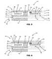
- FIGS. 7A and 7Bare simplified cross-sectional views of magnetic heads that include a heat dissipating structure in accordance with embodiments of the invention.
- FIGS. 8A and 8Bare simplified top views of magnetic heads that include a heat dissipating structure in accordance with embodiments of the invention.
- FIGS. 9A and 9Bare top views of magnetic heads that include a heat dissipating structure in accordance with embodiments of the invention.
- FIGS. 10A and 10Bare top views of magnetic heads that include a heat dissipating structure in accordance with embodiments of the invention.
- FIG. 11is a simplified cross-sectional view of the magnetic head depicted in FIG. 10 taken generally along line 11 — 11 , the head including a heat dissipating structure in accordance with embodiments of the invention.
- FIG. 1is an isometric view of a disc drive 100 in which embodiments of the present invention are useful.
- Disc drive 100includes a housing with a base 102 and a top cover (not shown).
- Disc drive 100further includes a disc pack 106 , which is mounted on a spindle motor (not shown) by a disc clamp 108 .
- Disc pack 106includes a plurality of individual discs, which are mounted for co-rotation about central axis 109 .
- Each disc surfacehas an associated read/write head 110 which is mounted to disc drive 100 for communication with the disc surface.
- heads 110are each carried by sliders that are supported by suspensions 112 , which are in turn attached to track accessing arms 114 of an actuator 116 .
- the actuator shown in FIG. 1is of the type known as a rotary moving coil actuator and includes a voice coil motor (VCM), shown generally at 118 .
- VCMvoice coil motor
- Voice coil motor 118rotates actuator 116 with its attached heads 110 about a pivot shaft 120 to position heads 110 over a desired data track along an arcuate path 122 between a disc inner diameter 124 and a disc outer diameter 126 .
- Voice coil motor 118is driven by servo electronics 130 based on signals generated by heads 110 and a host computer (not shown).
- FIG. 2is a simplified side cross-sectional view of a read/write head 110 in accordance with the prior art.
- Head 110includes a writer 132 and a reader 134 .
- Writer 132includes top and bottom writer poles 136 and 138 formed of a magnetically conductive material in top and bottom pole layers 140 and 142 (boundaries defined by dashed lines), respectively.
- Top writer pole 136includes a pole tip 144 that forms a portion of an air-bearing surface (ABS) 146 of head 110 and a back side 148 adjacent a back region 150 of head 110 .
- bottom writer pole 138includes a pole tip 152 that forms a portion of ABS 146 and a back side 154 adjacent back region 150 .
- ABSair-bearing surface
- Top and bottom writer poles 136 and 138are separated by a writer gap 156 and are connected at a back gap “via” 158 to form a C-shaped magnetic core.
- Writer 132also includes a conducting coil 160 formed in a coil layer 161 that extends between top and bottom writer poles 136 and 138 and around back gap 158 .
- Conducting coil 160includes a first portion 162 disposed between top and bottom writer poles 136 and 138 , and a second portion 164 that extends beyond top and bottom writer poles 136 and 138 and into back region 150 .
- a non-magnetic dielectric material 166is formed in writer gap 156 and insulates first portion 162 of conducting coil 160 from top and bottom writer poles 136 and 138 .
- the insulating material 166typically has a low thermal conductivity.
- Additional insulating material 168typically surrounds second portion 164 of conducting coil 160 outside of top and bottom writer poles 136 and 138 .
- insulating material 168is typically a non-magnetic dielectric material having a low thermal conductivity.
- Alumina (Al 2 O 3is one material that is typically used as insulating materials 166 and 168 .
- Reader 134includes a read element 174 that is positioned adjacent ABS 146 and between bottom writer pole 138 and a reader shield 176 that is formed in a reader shield layer 177 .
- Bottom writer pole 138 and reader shield 176operate to isolate the reading element 174 from external magnetic fields that could affect its sensing of bits of data that have been recorded on disc 178 .
- a magnetic circuitis formed in the writer 132 by top and bottom writer poles 136 and 138 , and back gap 158 .
- the depicted writer 132 of FIG. 2is configured for perpendicular recording, in which the magnetic circuit further includes a soft magnetic layer 179 of disc 178 , which underlays a hard magnetic or recording layer 180 .
- Recording layer 180includes vertical magnetic moments 182 , each of which represent a bit of data in accordance with their up or down orientation.
- an electrical currentis caused to flow in conducting coil 160 , which induces a magnetic field that is conducted through the magnetic circuit.
- the magnetic circuitcauses the magnetic field to travel through pole tip 144 and into recording layer 180 of disc 178 as indicated by arrow 184 .
- the magnetic fieldis directed through soft magnetic layer 179 of disc 178 , as indicated by arrow 186 , and then back through recording layer 180 to pole tip 152 of bottom writer pole 138 , as indicated by arrow 188 .
- the magnetic signalis conducted back to top writer pole 136 through a return path that includes bottom writer pole 138 and back gap 158 .
- the magnetic circuit for a writer that is configured to perform longitudinal recordingdoes not include the soft magnetic layer 179 of the disc 178 .
- the recording mediumincludes a recording layer (not shown) having horizontally aligned magnetic moments. Magnetic flux that fringes across a writer gap that is typically narrower than the depicted writer gap 156 from top writer pole 136 to bottom writer pole 138 and orients the magnetic moments in the direction of the magnetic field.
- Bottom writer pole 138receives magnetic signals from top writer pole 136 and, along with back gap 158 , provides a return path to conduct the signals back to top writer pole 136 .
- heads 110are formed smaller and are designed to operate closer to the disc 178 . Additionally, writer 132 and reader 134 of each of the heads 110 are configured to operate at higher frequencies. The higher operating frequency of the heads 110 results in an increase in the power that is applied to the writer 132 and reader 134 . As a result, a greater amount of heat is generated within the head 110 .
- typical head designscover second portion 164 of conducting coil 160 including back region 150 with insulating materials 168 having a low thermal conductance, such as alumina (Al 2 O 3 ), which is typically also used as insulating material 166 to insulate first portion 162 of conducting coil 160 and fill writer gap 156 , as mentioned above.
- aluminaAl 2 O 3
- high local temperature concentrationscan develop in writer 132 and reader 134 , which can cause their components to expand.
- Such thermal induced expansioncan deform the shape of head 110 , particularly at the interface between ABS 146 and disc 178 , which can cause an undesirable variation in the head-media spacing and a degradation in data reading and writing performance.
- the present inventionis generally directed to a magnetic head that includes a heat dissipating structure that conducts heat away from writer 132 and reader 134 and reduces the likelihood of thermally induced head deformation.
- the heat dissipating structuredraws heat from writer 132 and/or reader 134 and dissipates the heat away from an active region of the ABS 146 that is proximate the read element 124 and writer pole tips 144 and 152 to reduce thermally induced performance degradation in the head 110 .
- the heat dissipating structureis formed of a thermally conductive material that has a high thermal conductivity (K bulk ) of approximately 10 Watts/meter-Kelvin or greater, a high modulus of elasticity, and a coefficient of thermal expansion of approximately 6 ppm/° C. or less.
- K bulkthermal conductivity
- Examples of such preferred materialsinclude silicon carbide (SiC), aluminum nitride (AlN), tungsten (W), silicon (Si), and molybdenum (Mo), which provide greater thermal conductance than alumina.
- the thermally conductive materialcan be electrically conductive when it is separated from electrically sensitive elements, such as conducting coil 160 of writer 132 , by a thin isolation layer.
- the need for an isolation layercan be avoided when the thermally conductive material is a dielectric, such as silicon carbide, which can encapsulate electrically sensitive elements to maximize the efficiency of the heat transfer there between.
- the thermally conductive materialis preferably non-magnetic when, for example, it contacts either of the top or bottom writer poles 136 and 138 , or back gap 158 .
- FIGS. 3 and 4are simplified cross-sectional views of magnetic heads 110 that include a heat dissipating structure in the form of a bottom heat transfer sheet 200 .
- bottom heat transfer sheet 200is formed in bottom pole layer 142 such that it underlays second portion 164 of conducting coil 160 .
- bottom heat transfer sheet 200is displaced slightly from back side 154 of bottom writer pole 138 by a gap 202 that is filled with a non-magnetic material.
- Gap 202is preferably formed as small as possible (e.g., 0.25 microns) to maximize heat transfer from the bottom pole 138 to the bottom heat transfer sheet 200 without affecting the performance of writer 132 . This provides an effective thermal pathway through the head 110 and away from ABS 146 while allowing free selection of the thermally conductive material used to form the bottom heat transfer sheet 200 .
- Bottom heat transfer sheet 200is preferably formed of a non-magnetic dielectric material to reduce capacitive coupling from writer 132 to reader 134 and stray dynamic magnetic losses.
- bottom heat transfer sheet 200can also be formed of the same magnetically conductive material that form the bottom writer pole 138 . This allows bottom heat transfer sheet 200 to be formed during the same fabrication step of bottom writer pole 138 .
- a global depositionmay be used to form bottom writer pole 138 and bottom heat transfer sheet 200 outside of the mask used to form bottom writer pole 138 or within a recessed patterned feature behind back side 154 of bottom writer pole 138 .
- bottom heat transfer sheet 200can extend beyond bottom pole layer 142 .
- bottom heat transfer sheet 200extends into reader shield layer 177 in which the reader shield 176 is formed, as shown in FIG. 4 .
- Bottom heat transfer sheet 200can be formed to contact back side 206 of the reader shield 176 , or be displaced therefrom by gap 208 .
- This embodiment of bottom heat transfer sheet 200further enhances heat dissipation by conducting heat away from reader shield 176 .
- the larger size of bottom heat transfer sheet 200also contributes to greater heat absorption from writer 132 and reader 134 .
- bottom heat transfer sheet 200can be configured to contact a bottom side 210 of second portion 164 of conducting coil 160 , as shown in FIG. 4 , when bottom heat transfer sheet 200 is formed of a dielectric material.
- bottom heat transfer sheet 200can be formed of an electrical conductor when it is displaced from bottom side 210 by an isolation layer 212 formed of an electrically insulating material, as shown in FIG. 3 .
- Isolation layer 212preferably has a thickness of approximately 0.1 microns.
- top heat transfer sheet 214that overlays second portion 164 of conducting coil 160 .
- top heat transfer sheet 214is at least partially formed in top pole layer 140 .
- bottom heat transfer sheet 200such a configuration allows top heat transfer sheet 214 to be formed during the same processing step as top writer pole 136 .
- top heat transfer sheet 214is displaced from conducting coil 160 by a gap 215 and from back side 148 of top writer pole 136 by a gap 216 as shown in FIG. 5
- Each gap 215 and 216is filled with an electrically insulating material.
- top heat transfer sheet 214is displaced from top writer pole 136 and a top contact 218 of the conducting coil 160 by the gap 216 .
- top heat transfer sheet 214can include first and second portions 214 A and 214 B that are positioned to respectively cover first and second sides 220 A and 220 B of second portion 164 of conducting coil 160 .
- Top heat transfer sheet portions 214 A and 214 Bcan also cover the second portion 164 of the conducting coil 160 lying in the back region 150 of the head 110 .
- top heat transfer sheet 214is a dielectric, which allows top heat transfer sheet 214 to contact a top side 222 of second portion 164 of conducting coil 160 including top contact 218 , as illustrated in FIG. 6 .
- Such a configurationis also illustrated in the simplified top view of the head 110 in FIGS. 9A and 9B .
- Top heat transfer sheet 214can also overlay top writer pole 136 as shown in FIGS. 6 , 10 A and 10 B.
- top heat transfer sheet 214contacts a top side 224 of the top writer pole 136 , as shown in FIG. 6 , and is formed of a non-magnetic material.
- top heat transfer sheet 214can be displaced from top side 224 of top writer pole 136 , as shown in FIGS. 7A and 7B .
- the heat dissipating structurecan include a non-magnetic heat transfer segment 226 that connects top heat transfer sheet 214 to top surface 224 of top writer pole 136 through direct contact, as shown in FIG. 7 A.
- heat transfer segment 226can be separated from top side 224 of top writer pole 136 by a thin isolation or spacer layer 228 as shown in FIG. 7B , when necessary. As a result, the hottest portions of top writer pole 136 can be “tapped” by heat transfer segment 226 .
- the heat transfer segment 226can be formed using a stud process or other suitable method.
- top heat transfer sheet 214can cover the entire second portion 164 of conducting coil 160 , or portions thereof. Additionally, top heat transfer sheet 214 can extend toward ABS 146 to increase heat transfer from the active region of ABS 146 . In accordance with one embodiment of the invention, top heat transfer sheet 214 is displaced slightly from ABS 146 of head 110 , as shown in FIGS. 8A , 9 A and 10 A. This configuration avoids manufacturing constraints and allows for a wider range of materials to be used to form top heat transfer sheet 214 . Alternatively, top heat transfer sheet 214 can extend to the ABS 146 to maximize the heat transfer from the active region, as shown in FIGS. 8B , 9 B and 10 B. In accordance with this embodiment, top heat transfer sheet preferably includes a notch 230 to recess top heat transfer sheet 214 from ABS 146 at the active region to prevent interference with the reading and writing operations of head 110 .
- FIG. 11is a simplified cross-sectional view of head 110 that is taken along line 11 — 11 of FIG. 10A.
- a first side heat transfer member 232 Ais formed in coil layer 161 adjacent first side 220 A of second portion 164 of conducting coil 160 .
- a second side heat transfer member 232 Bcan be formed in coil layer 161 adjacent second side 220 B of second portion 164 of conducting coil 160 .
- the side heat transfer members 232are isolated from conducting coil 160 by an electrically insulating material fill 234 that is formed between the conducting coil segments. This configuration allows side heat transfer members 232 to be formed of the same material as conducting coil 160 .
- side heat transfer members 232are formed of a suitable dielectric, they can be placed in direct contact with conducting coil 160 .
- the heat dissipating structure of the present inventioncan include any combination of the above-described structures. Accordingly, the heat dissipating structure can include an embodiment of top heat transfer sheet 214 , an embodiment of bottom heat transfer sheet 200 , and/or an embodiment of side heat transfer members 232 .
- the heat dissipating structurecan include first and second side heat transfer members 232 A and 232 B, top heat transfer sheet 214 , and bottom heat transfer sheet 200 .
- the heat dissipating structurecan include thermally conductive segments 236 A and 236 B can respectively join first and second side heat transfer members 232 A and 232 B to top heat transfer sheet 214 .
- the heat dissipating structurecan include thermally conductive segments 238 A and 238 B that respectively join first and second side heat transfer members 232 A and 232 B to bottom heat transfer sheet 200 .
- the present inventionis directed to a magnetic head (such as 110 ) that includes a heat dissipating structure that improves the dissipation of heat therein to reduce thermally induced performance degradation.
- the magnetic headincludes top and bottom writer poles (such as 136 and 138 ), a writer conducting coil (such as 160 ), and the heat dissipating structure.
- the top and bottom writer polesare respectively formed in top and bottom pole layers (such as 140 and 142 ).
- Each writer poleincludes a pole tip (such as 144 and 152 ) at an air-bearing surface (such as 146 ) and a back side (such as 148 and 154 ) adjacent a back region (such as 150 ).
- the conducting coilis formed in a coil layer (such as 162 ), extends from the air-bearing surface and includes a first portion (such as 162 ) that is disposed between the top and bottom writer poles and a second portion (such as 164 ) that is disposed in the back region.
- a coil layersuch as 162
- the conducting coilis formed in a coil layer (such as 162 ), extends from the air-bearing surface and includes a first portion (such as 162 ) that is disposed between the top and bottom writer poles and a second portion (such as 164 ) that is disposed in the back region.
- the heat dissipating structureis formed of a thermally conductive material and includes a top heat transfer sheet (such as 214 ) overlaying the second portion of the conducting coil; a bottom heat transfer sheet (such as 200 ) that is displaced from the back side of the bottom writer pole and underlays the second portion of the conducting coil; a first side heat transfer member (such as 232 A) formed in the coil layer adjacent a first side (such as 220 A) of the conducting coil; and/or a second side heat transfer member (such as 232 B) formed in the coil layer adjacent a second side (such as 220 B) of the conducting coil.
Landscapes
- Engineering & Computer Science (AREA)
- Manufacturing & Machinery (AREA)
- Physics & Mathematics (AREA)
- Electromagnetism (AREA)
- Magnetic Heads (AREA)
Abstract
Description
Claims (28)
Priority Applications (1)
| Application Number | Priority Date | Filing Date | Title |
|---|---|---|---|
| US10/383,140US6950280B2 (en) | 2002-10-29 | 2003-03-06 | Magnetic head having a heat dissipating structure |
Applications Claiming Priority (2)
| Application Number | Priority Date | Filing Date | Title |
|---|---|---|---|
| US42208502P | 2002-10-29 | 2002-10-29 | |
| US10/383,140US6950280B2 (en) | 2002-10-29 | 2003-03-06 | Magnetic head having a heat dissipating structure |
Publications (2)
| Publication Number | Publication Date |
|---|---|
| US20040080869A1 US20040080869A1 (en) | 2004-04-29 |
| US6950280B2true US6950280B2 (en) | 2005-09-27 |
Family
ID=32109971
Family Applications (1)
| Application Number | Title | Priority Date | Filing Date |
|---|---|---|---|
| US10/383,140Expired - Fee RelatedUS6950280B2 (en) | 2002-10-29 | 2003-03-06 | Magnetic head having a heat dissipating structure |
Country Status (1)
| Country | Link |
|---|---|
| US (1) | US6950280B2 (en) |
Cited By (14)
| Publication number | Priority date | Publication date | Assignee | Title |
|---|---|---|---|---|
| US20040165311A1 (en)* | 2003-02-26 | 2004-08-26 | Tdk Corporation | Thin-film magnetic head, head gimbal assembly, and hard disk drive |
| US20040169950A1 (en)* | 2002-02-27 | 2004-09-02 | Seagate Technology Llc | Inductive write head driven only by an ampere wire |
| US20050047015A1 (en)* | 2003-08-29 | 2005-03-03 | Tdk Corporation | Thin film magnetic head and magnetic recording apparatus |
| US20060028771A1 (en)* | 2002-04-10 | 2006-02-09 | Tdk Corporation | Thin film magnetic head, method of manufacturing the same, and magnetic disk drive |
| US20070177300A1 (en)* | 2006-01-31 | 2007-08-02 | Seagate Technology Llc | Transducer including an element of a transducer and a sidewall in an electrically conductive magnetic layer |
| US20080024896A1 (en)* | 2006-07-27 | 2008-01-31 | Tdk Corporation | Heat-assisted magnetic recording method using eddy current and head for heat-assisted magnetic recording |
| US20080030905A1 (en)* | 2006-08-01 | 2008-02-07 | Alps Electric Co., Ltd. | Perpendicular magnetic recording head including heating element |
| US20080068762A1 (en)* | 2006-09-20 | 2008-03-20 | Kiyoshi Kobayashi | Thin film magnetic head including thermal deformation-preventing layer |
| US20080253032A1 (en)* | 2007-03-29 | 2008-10-16 | Tdk Corporation | Thin film magnetic head, head gimbal assembly, head arm assembly, magnetic disk device and method of forming thin film magnetic head |
| US20090237837A1 (en)* | 2008-03-19 | 2009-09-24 | Seagate Technology Llc | Magnetic recording head |
| US10032468B1 (en) | 2015-11-06 | 2018-07-24 | Seagate Technology Llc | Heat-assisted magnetic recording head configured to conduct heat away from slider components to a substrate |
| US10049693B2 (en) | 2016-08-03 | 2018-08-14 | Seagate Technology Llc | Substrate heat channels for heat assisted magnetic recording for reader over writer transducer application |
| US10074386B1 (en) | 2015-05-19 | 2018-09-11 | Seagate Technology Llc | Magnetic writer coil incorporating integral cooling fins |
| US10636439B2 (en) | 2017-12-19 | 2020-04-28 | Western Digital Technologies, Inc. | MAMR write head with thermal dissipation conductive guide |
Families Citing this family (9)
| Publication number | Priority date | Publication date | Assignee | Title |
|---|---|---|---|---|
| US7522379B1 (en)* | 2004-07-30 | 2009-04-21 | Western Digital (Fremont), Llc | Write element with recessed pole and heat sink layer for ultra-high density writing |
| US7379269B1 (en) | 2004-07-30 | 2008-05-27 | Western Digital (Fremont), Llc | Write element with reduced yoke length for ultra-high density writing |
| US20060098337A1 (en)* | 2004-11-10 | 2006-05-11 | Hung-Chin Guthrie | Tungsten heat sink structures in a thin film magnetic head |
| US7411264B2 (en)* | 2004-11-18 | 2008-08-12 | Seagate Technology Llc | Etch-stop layers for patterning block structures for reducing thermal protrusion |
| US7639453B2 (en)* | 2006-08-01 | 2009-12-29 | Hitachi Global Storage Technologies Netherlands B.V. | Perpendicular magnetic write head with shunt structure to prevent read sensor interference |
| US7646132B2 (en)* | 2007-05-02 | 2010-01-12 | Empire Magnetics Inc. | Arcuate coil winding and assembly for axial gap electro-dynamo machines (EDM) |
| WO2009100426A2 (en)* | 2008-02-08 | 2009-08-13 | Empire Magnetics Inc. | Nested serpentine winding for an axial gap electric dynamo machine |
| WO2009100436A2 (en)* | 2008-02-10 | 2009-08-13 | Empire Magnetics Inc. | Winding for an axial gap electro dynamo machine |
| US7821168B2 (en)* | 2008-02-10 | 2010-10-26 | Empire Magnetics Inc. | Axial gap dynamo electric machine with magnetic bearing |
Citations (20)
| Publication number | Priority date | Publication date | Assignee | Title |
|---|---|---|---|---|
| US5361242A (en) | 1990-02-07 | 1994-11-01 | Canon Kabushiki Kaisha | External magnetic field application device including a heat dissipation member and a metal plate for dissipating heat |
| US5617071A (en) | 1992-11-16 | 1997-04-01 | Nonvolatile Electronics, Incorporated | Magnetoresistive structure comprising ferromagnetic thin films and intermediate alloy layer having magnetic concentrator and shielding permeable masses |
| US5644455A (en) | 1993-12-30 | 1997-07-01 | Seagate Technology, Inc. | Amorphous diamond-like carbon gaps in magnetoresistive heads |
| US5919567A (en) | 1996-05-28 | 1999-07-06 | Mitsubishi Denki Kabushiki Kaisha | Magnetic head |
| US5930084A (en) | 1996-06-17 | 1999-07-27 | International Business Machines Corporation | Stabilized MR sensor and flux guide joined by contiguous junction |
| US5930086A (en) | 1997-05-02 | 1999-07-27 | Storage Technology Corporation | Heat exchangeable thin-film recording head element and method for manufacturing same |
| US5936806A (en) | 1998-03-06 | 1999-08-10 | International Business Machines Corporation | Flying head slider and suspension assembly with stress relief for controlling slider crown thermal sensitivity |
| US5991113A (en) | 1997-04-07 | 1999-11-23 | Seagate Technology, Inc. | Slider with temperature responsive transducer positioning |
| US6188549B1 (en) | 1997-12-10 | 2001-02-13 | Read-Rite Corporation | Magnetoresistive read/write head with high-performance gap layers |
| US6252749B1 (en) | 1997-09-17 | 2001-06-26 | Alps Electric Co., Ltd. | Thin film magnetic head having a gap layer with improved thermal conductivity |
| US6307720B1 (en) | 1998-04-24 | 2001-10-23 | Alps Electric Co., Ltd. | Thin film magnetic head |
| US6381094B1 (en) | 1999-07-23 | 2002-04-30 | Hardayal Singh Gill | Shield structure with a heat sink layer for dissipating heat from a read sensor |
| US6396670B1 (en) | 1998-07-21 | 2002-05-28 | Seagate Technology Llc | Reducing sensor temperature in magnetoresistive recording heads |
| US6396660B1 (en) | 1999-08-23 | 2002-05-28 | Read-Rite Corporation | Magnetic write element having a thermally dissipative structure |
| US6404603B1 (en) | 1998-10-06 | 2002-06-11 | Tdk Corporation | Thin film device, thin film head, and magnetoresistive element |
| US6459551B1 (en) | 1998-12-21 | 2002-10-01 | Alps Electric Co., Ltd. | Thin film magnetic head |
| US6493183B1 (en) | 2000-06-29 | 2002-12-10 | International Business Machines Corporation | Thermally-assisted magnetic recording system with head having resistive heater in write gap |
| US6760191B1 (en)* | 2001-06-18 | 2004-07-06 | Maxtor Corporation | Internal heat dissipater used to reduce slider and write pole thermal protrusion for thin film recording heads |
| US20040246630A1 (en)* | 2003-06-04 | 2004-12-09 | Alps Electric Co., Ltd. | Magnetic head including metallic material layer between write head section and read head section |
| US6859343B1 (en)* | 2002-03-19 | 2005-02-22 | Western Digital, Inc. | Hybrid diffuser for minimizing thermal pole tip protrusion and reader sensor temperature |
- 2003
- 2003-03-06USUS10/383,140patent/US6950280B2/ennot_activeExpired - Fee Related
Patent Citations (22)
| Publication number | Priority date | Publication date | Assignee | Title |
|---|---|---|---|---|
| US5361242A (en) | 1990-02-07 | 1994-11-01 | Canon Kabushiki Kaisha | External magnetic field application device including a heat dissipation member and a metal plate for dissipating heat |
| US5617071A (en) | 1992-11-16 | 1997-04-01 | Nonvolatile Electronics, Incorporated | Magnetoresistive structure comprising ferromagnetic thin films and intermediate alloy layer having magnetic concentrator and shielding permeable masses |
| US5644455A (en) | 1993-12-30 | 1997-07-01 | Seagate Technology, Inc. | Amorphous diamond-like carbon gaps in magnetoresistive heads |
| US5919567A (en) | 1996-05-28 | 1999-07-06 | Mitsubishi Denki Kabushiki Kaisha | Magnetic head |
| US6181532B1 (en) | 1996-06-17 | 2001-01-30 | International Business Machines Corporation | Stabilized MR sensor and flux/heat guide joined by contiguous junction |
| US5930084A (en) | 1996-06-17 | 1999-07-27 | International Business Machines Corporation | Stabilized MR sensor and flux guide joined by contiguous junction |
| US6239955B1 (en) | 1996-06-17 | 2001-05-29 | International Business Machines Corporation | Stabilized MR sensor and heat guide joined by contiguous junction |
| US5991113A (en) | 1997-04-07 | 1999-11-23 | Seagate Technology, Inc. | Slider with temperature responsive transducer positioning |
| US5930086A (en) | 1997-05-02 | 1999-07-27 | Storage Technology Corporation | Heat exchangeable thin-film recording head element and method for manufacturing same |
| US6252749B1 (en) | 1997-09-17 | 2001-06-26 | Alps Electric Co., Ltd. | Thin film magnetic head having a gap layer with improved thermal conductivity |
| US6188549B1 (en) | 1997-12-10 | 2001-02-13 | Read-Rite Corporation | Magnetoresistive read/write head with high-performance gap layers |
| US5936806A (en) | 1998-03-06 | 1999-08-10 | International Business Machines Corporation | Flying head slider and suspension assembly with stress relief for controlling slider crown thermal sensitivity |
| US6307720B1 (en) | 1998-04-24 | 2001-10-23 | Alps Electric Co., Ltd. | Thin film magnetic head |
| US6396670B1 (en) | 1998-07-21 | 2002-05-28 | Seagate Technology Llc | Reducing sensor temperature in magnetoresistive recording heads |
| US6404603B1 (en) | 1998-10-06 | 2002-06-11 | Tdk Corporation | Thin film device, thin film head, and magnetoresistive element |
| US6459551B1 (en) | 1998-12-21 | 2002-10-01 | Alps Electric Co., Ltd. | Thin film magnetic head |
| US6381094B1 (en) | 1999-07-23 | 2002-04-30 | Hardayal Singh Gill | Shield structure with a heat sink layer for dissipating heat from a read sensor |
| US6396660B1 (en) | 1999-08-23 | 2002-05-28 | Read-Rite Corporation | Magnetic write element having a thermally dissipative structure |
| US6493183B1 (en) | 2000-06-29 | 2002-12-10 | International Business Machines Corporation | Thermally-assisted magnetic recording system with head having resistive heater in write gap |
| US6760191B1 (en)* | 2001-06-18 | 2004-07-06 | Maxtor Corporation | Internal heat dissipater used to reduce slider and write pole thermal protrusion for thin film recording heads |
| US6859343B1 (en)* | 2002-03-19 | 2005-02-22 | Western Digital, Inc. | Hybrid diffuser for minimizing thermal pole tip protrusion and reader sensor temperature |
| US20040246630A1 (en)* | 2003-06-04 | 2004-12-09 | Alps Electric Co., Ltd. | Magnetic head including metallic material layer between write head section and read head section |
Cited By (29)
| Publication number | Priority date | Publication date | Assignee | Title |
|---|---|---|---|---|
| US20040169950A1 (en)* | 2002-02-27 | 2004-09-02 | Seagate Technology Llc | Inductive write head driven only by an ampere wire |
| US7149055B2 (en)* | 2002-02-27 | 2006-12-12 | Seagate Technology Llc | Inductive write head driven only by an ampere wire |
| US20060028771A1 (en)* | 2002-04-10 | 2006-02-09 | Tdk Corporation | Thin film magnetic head, method of manufacturing the same, and magnetic disk drive |
| US7088560B2 (en)* | 2002-04-10 | 2006-08-08 | Tdk Corporation | Thin film magnetic head including a heat dissipation layer, method of manufacturing the same and magnetic disk drive |
| US20040165311A1 (en)* | 2003-02-26 | 2004-08-26 | Tdk Corporation | Thin-film magnetic head, head gimbal assembly, and hard disk drive |
| US7420776B2 (en)* | 2003-02-26 | 2008-09-02 | Tdk Corporation | Thin-film magnetic head, head gimbal assembly, and hard disk drive |
| US7187521B2 (en)* | 2003-02-26 | 2007-03-06 | Tdk Corporation | Thin-film magnetic head, head gimbal assembly, and hard disk drive |
| US20070103814A1 (en)* | 2003-02-26 | 2007-05-10 | Tdk Corporation | Thin-film magnetic head, head gimbal assembly, and hard disk drive |
| US7391590B2 (en)* | 2003-08-29 | 2008-06-24 | Tdk Corporation | Thin film magnetic head and magnetic recording apparatus with partitioned heat sink layer |
| US20050047015A1 (en)* | 2003-08-29 | 2005-03-03 | Tdk Corporation | Thin film magnetic head and magnetic recording apparatus |
| US20070177300A1 (en)* | 2006-01-31 | 2007-08-02 | Seagate Technology Llc | Transducer including an element of a transducer and a sidewall in an electrically conductive magnetic layer |
| US20110179634A1 (en)* | 2006-01-31 | 2011-07-28 | Seagate Technology Llc | Method of making a transducer with a conductive magnetic layer |
| US7948714B2 (en) | 2006-01-31 | 2011-05-24 | Seagate Technology Llc | Transducer including an element of a transducer and a sidewall in an electrically conductive magnetic layer |
| US20080024896A1 (en)* | 2006-07-27 | 2008-01-31 | Tdk Corporation | Heat-assisted magnetic recording method using eddy current and head for heat-assisted magnetic recording |
| US7952827B2 (en)* | 2006-07-27 | 2011-05-31 | Tdk Corporation | Heat-assisted magnetic recording method using eddy current and head for heat-assisted magnetic recording |
| US20080030905A1 (en)* | 2006-08-01 | 2008-02-07 | Alps Electric Co., Ltd. | Perpendicular magnetic recording head including heating element |
| US7898767B2 (en)* | 2006-08-01 | 2011-03-01 | Tdk Corporation | Perpendicular magnetic recording head including heating element |
| US8045293B2 (en)* | 2006-09-20 | 2011-10-25 | Tdk Corporation | Thin film magnetic head including thermal deformation-preventing layer |
| US20080068762A1 (en)* | 2006-09-20 | 2008-03-20 | Kiyoshi Kobayashi | Thin film magnetic head including thermal deformation-preventing layer |
| US7787215B2 (en)* | 2007-03-29 | 2010-08-31 | Tdk Corporation | Thin film magnetic head in which thermal protrusion is suppressed and method of forming the same |
| US20080253032A1 (en)* | 2007-03-29 | 2008-10-16 | Tdk Corporation | Thin film magnetic head, head gimbal assembly, head arm assembly, magnetic disk device and method of forming thin film magnetic head |
| US20090237837A1 (en)* | 2008-03-19 | 2009-09-24 | Seagate Technology Llc | Magnetic recording head |
| US8286333B2 (en) | 2008-03-19 | 2012-10-16 | Seagate Technology Llc | Method of manufacturing a magnetic head |
| US10074386B1 (en) | 2015-05-19 | 2018-09-11 | Seagate Technology Llc | Magnetic writer coil incorporating integral cooling fins |
| US10032468B1 (en) | 2015-11-06 | 2018-07-24 | Seagate Technology Llc | Heat-assisted magnetic recording head configured to conduct heat away from slider components to a substrate |
| US10147446B1 (en) | 2015-11-06 | 2018-12-04 | Seagate Technology Llc | Heat-assisted magnetic recording head configured to conduct heat away from slider components to a substrate |
| US10049693B2 (en) | 2016-08-03 | 2018-08-14 | Seagate Technology Llc | Substrate heat channels for heat assisted magnetic recording for reader over writer transducer application |
| US10636439B2 (en) | 2017-12-19 | 2020-04-28 | Western Digital Technologies, Inc. | MAMR write head with thermal dissipation conductive guide |
| US10762918B2 (en) | 2017-12-19 | 2020-09-01 | Western Digital Technologies, Inc. | MAMR write head with thermal dissipation conductive guide |
Also Published As
| Publication number | Publication date |
|---|---|
| US20040080869A1 (en) | 2004-04-29 |
Similar Documents
| Publication | Publication Date | Title |
|---|---|---|
| US6950280B2 (en) | Magnetic head having a heat dissipating structure | |
| US7054113B1 (en) | Reader/writer for magnetic memory | |
| US6381094B1 (en) | Shield structure with a heat sink layer for dissipating heat from a read sensor | |
| US6760191B1 (en) | Internal heat dissipater used to reduce slider and write pole thermal protrusion for thin film recording heads | |
| US7092208B2 (en) | Magnetic transducers with reduced thermal pole-tip protrusion/recession | |
| US5644455A (en) | Amorphous diamond-like carbon gaps in magnetoresistive heads | |
| US7656619B1 (en) | Magnetic head sliders for disk drives having a heating element and pedestal in thick undercoat layer | |
| US7170713B2 (en) | Heat sink for a magnetic recording head | |
| US20060028765A1 (en) | Magnetic head having a heater circuit for thermally-assisted writing | |
| US6813118B2 (en) | Transducing head having improved studs and bond pads to reduce thermal deformation | |
| JP4883930B2 (en) | Recording head reduces side track erasure | |
| US20060023367A1 (en) | Eliminating ESD exposure for read/write head with heating element | |
| US6775108B2 (en) | Magnetic head having a read element shield and substrate with matching coefficients of thermal expansion | |
| US7320168B2 (en) | Method to improve heat dissipation in a magnetic shield | |
| US20030231435A1 (en) | Shared pole design for reduced thermal pole tip protrusion | |
| US7301727B2 (en) | Return pole of a transducer having low thermal induced protrusion | |
| US7123447B2 (en) | Patterned multi-material basecoat to reduce thermal protrusion | |
| US7035047B2 (en) | Magnetic recording heads having thin thermally conductive undercoating | |
| EP1398763B1 (en) | Heat sink for a magnetic recording head | |
| US7009818B1 (en) | Thin film magnetic head having improved thermal characteristics, and method of manufacturing | |
| US6842306B2 (en) | Magnetic head having highly thermally conductive insulator materials containing cobalt-oxide | |
| US6842316B2 (en) | Magnetic spin valve sensor having an exchange stabilization layer recessed from the active track edge | |
| US20100053794A1 (en) | Thermally assisted magnetic recording method, magnetic recording head, magnetic recording medium, and magnetic recording apparatus | |
| US20060092576A1 (en) | Magnetic head for high speed data transfer | |
| JP2005085432A (en) | Thin film magnetic head and magnetic disk device |
Legal Events
| Date | Code | Title | Description |
|---|---|---|---|
| AS | Assignment | Owner name:SEAGATE TECHNOLOGY LLC, CALIFORNIA Free format text:ASSIGNMENT OF ASSIGNORS INTEREST;ASSIGNORS:REA, CHRISTOPHER JAMES THOMPSON;PUST, LADISLAV RUDOLPH;KAUTZKY, MICHAEL CHRISTOPHER;AND OTHERS;REEL/FRAME:013858/0108;SIGNING DATES FROM 20030221 TO 20030226 | |
| FEPP | Fee payment procedure | Free format text:PAYOR NUMBER ASSIGNED (ORIGINAL EVENT CODE: ASPN); ENTITY STATUS OF PATENT OWNER: LARGE ENTITY | |
| FPAY | Fee payment | Year of fee payment:4 | |
| AS | Assignment | Owner name:WELLS FARGO BANK, NATIONAL ASSOCIATION, AS COLLATERAL AGENT AND SECOND PRIORITY REPRESENTATIVE, CALIFORNIA Free format text:SECURITY AGREEMENT;ASSIGNORS:MAXTOR CORPORATION;SEAGATE TECHNOLOGY LLC;SEAGATE TECHNOLOGY INTERNATIONAL;REEL/FRAME:022757/0017 Effective date:20090507 Owner name:JPMORGAN CHASE BANK, N.A., AS ADMINISTRATIVE AGENT AND FIRST PRIORITY REPRESENTATIVE, NEW YORK Free format text:SECURITY AGREEMENT;ASSIGNORS:MAXTOR CORPORATION;SEAGATE TECHNOLOGY LLC;SEAGATE TECHNOLOGY INTERNATIONAL;REEL/FRAME:022757/0017 Effective date:20090507 Owner name:JPMORGAN CHASE BANK, N.A., AS ADMINISTRATIVE AGENT Free format text:SECURITY AGREEMENT;ASSIGNORS:MAXTOR CORPORATION;SEAGATE TECHNOLOGY LLC;SEAGATE TECHNOLOGY INTERNATIONAL;REEL/FRAME:022757/0017 Effective date:20090507 Owner name:WELLS FARGO BANK, NATIONAL ASSOCIATION, AS COLLATE Free format text:SECURITY AGREEMENT;ASSIGNORS:MAXTOR CORPORATION;SEAGATE TECHNOLOGY LLC;SEAGATE TECHNOLOGY INTERNATIONAL;REEL/FRAME:022757/0017 Effective date:20090507 | |
| AS | Assignment | Owner name:SEAGATE TECHNOLOGY INTERNATIONAL, CALIFORNIA Free format text:RELEASE;ASSIGNOR:JPMORGAN CHASE BANK, N.A., AS ADMINISTRATIVE AGENT;REEL/FRAME:025662/0001 Effective date:20110114 Owner name:SEAGATE TECHNOLOGY HDD HOLDINGS, CALIFORNIA Free format text:RELEASE;ASSIGNOR:JPMORGAN CHASE BANK, N.A., AS ADMINISTRATIVE AGENT;REEL/FRAME:025662/0001 Effective date:20110114 Owner name:MAXTOR CORPORATION, CALIFORNIA Free format text:RELEASE;ASSIGNOR:JPMORGAN CHASE BANK, N.A., AS ADMINISTRATIVE AGENT;REEL/FRAME:025662/0001 Effective date:20110114 Owner name:SEAGATE TECHNOLOGY LLC, CALIFORNIA Free format text:RELEASE;ASSIGNOR:JPMORGAN CHASE BANK, N.A., AS ADMINISTRATIVE AGENT;REEL/FRAME:025662/0001 Effective date:20110114 | |
| AS | Assignment | Owner name:THE BANK OF NOVA SCOTIA, AS ADMINISTRATIVE AGENT, CANADA Free format text:SECURITY AGREEMENT;ASSIGNOR:SEAGATE TECHNOLOGY LLC;REEL/FRAME:026010/0350 Effective date:20110118 Owner name:THE BANK OF NOVA SCOTIA, AS ADMINISTRATIVE AGENT, Free format text:SECURITY AGREEMENT;ASSIGNOR:SEAGATE TECHNOLOGY LLC;REEL/FRAME:026010/0350 Effective date:20110118 | |
| FPAY | Fee payment | Year of fee payment:8 | |
| AS | Assignment | Owner name:SEAGATE TECHNOLOGY LLC, CALIFORNIA Free format text:TERMINATION AND RELEASE OF SECURITY INTEREST IN PATENT RIGHTS;ASSIGNOR:WELLS FARGO BANK, NATIONAL ASSOCIATION, AS COLLATERAL AGENT AND SECOND PRIORITY REPRESENTATIVE;REEL/FRAME:030833/0001 Effective date:20130312 Owner name:SEAGATE TECHNOLOGY INTERNATIONAL, CAYMAN ISLANDS Free format text:TERMINATION AND RELEASE OF SECURITY INTEREST IN PATENT RIGHTS;ASSIGNOR:WELLS FARGO BANK, NATIONAL ASSOCIATION, AS COLLATERAL AGENT AND SECOND PRIORITY REPRESENTATIVE;REEL/FRAME:030833/0001 Effective date:20130312 Owner name:EVAULT INC. (F/K/A I365 INC.), CALIFORNIA Free format text:TERMINATION AND RELEASE OF SECURITY INTEREST IN PATENT RIGHTS;ASSIGNOR:WELLS FARGO BANK, NATIONAL ASSOCIATION, AS COLLATERAL AGENT AND SECOND PRIORITY REPRESENTATIVE;REEL/FRAME:030833/0001 Effective date:20130312 Owner name:SEAGATE TECHNOLOGY US HOLDINGS, INC., CALIFORNIA Free format text:TERMINATION AND RELEASE OF SECURITY INTEREST IN PATENT RIGHTS;ASSIGNOR:WELLS FARGO BANK, NATIONAL ASSOCIATION, AS COLLATERAL AGENT AND SECOND PRIORITY REPRESENTATIVE;REEL/FRAME:030833/0001 Effective date:20130312 | |
| REMI | Maintenance fee reminder mailed | ||
| LAPS | Lapse for failure to pay maintenance fees | Free format text:PATENT EXPIRED FOR FAILURE TO PAY MAINTENANCE FEES (ORIGINAL EVENT CODE: EXP.) | |
| STCH | Information on status: patent discontinuation | Free format text:PATENT EXPIRED DUE TO NONPAYMENT OF MAINTENANCE FEES UNDER 37 CFR 1.362 | |
| FP | Lapsed due to failure to pay maintenance fee | Effective date:20170927 | |
| AS | Assignment | Owner name:SEAGATE TECHNOLOGY PUBLIC LIMITED COMPANY, CALIFORNIA Free format text:RELEASE BY SECURED PARTY;ASSIGNOR:THE BANK OF NOVA SCOTIA;REEL/FRAME:072193/0001 Effective date:20250303 Owner name:SEAGATE TECHNOLOGY, CALIFORNIA Free format text:RELEASE BY SECURED PARTY;ASSIGNOR:THE BANK OF NOVA SCOTIA;REEL/FRAME:072193/0001 Effective date:20250303 Owner name:SEAGATE TECHNOLOGY HDD HOLDINGS, CALIFORNIA Free format text:RELEASE BY SECURED PARTY;ASSIGNOR:THE BANK OF NOVA SCOTIA;REEL/FRAME:072193/0001 Effective date:20250303 Owner name:I365 INC., CALIFORNIA Free format text:RELEASE BY SECURED PARTY;ASSIGNOR:THE BANK OF NOVA SCOTIA;REEL/FRAME:072193/0001 Effective date:20250303 Owner name:SEAGATE TECHNOLOGY LLC, CALIFORNIA Free format text:RELEASE BY SECURED PARTY;ASSIGNOR:THE BANK OF NOVA SCOTIA;REEL/FRAME:072193/0001 Effective date:20250303 Owner name:SEAGATE TECHNOLOGY INTERNATIONAL, CAYMAN ISLANDS Free format text:RELEASE BY SECURED PARTY;ASSIGNOR:THE BANK OF NOVA SCOTIA;REEL/FRAME:072193/0001 Effective date:20250303 Owner name:SEAGATE HDD CAYMAN, CAYMAN ISLANDS Free format text:RELEASE BY SECURED PARTY;ASSIGNOR:THE BANK OF NOVA SCOTIA;REEL/FRAME:072193/0001 Effective date:20250303 Owner name:SEAGATE TECHNOLOGY (US) HOLDINGS, INC., CALIFORNIA Free format text:RELEASE BY SECURED PARTY;ASSIGNOR:THE BANK OF NOVA SCOTIA;REEL/FRAME:072193/0001 Effective date:20250303 |