US6950032B1 - Apparatus and method for protection against appliance leaking - Google Patents
Apparatus and method for protection against appliance leakingDownload PDFInfo
- Publication number
- US6950032B1 US6950032B1US10/027,225US2722501AUS6950032B1US 6950032 B1US6950032 B1US 6950032B1US 2722501 AUS2722501 AUS 2722501AUS 6950032 B1US6950032 B1US 6950032B1
- Authority
- US
- United States
- Prior art keywords
- water
- switch
- power supply
- valve assembly
- container
- Prior art date
- Legal status (The legal status is an assumption and is not a legal conclusion. Google has not performed a legal analysis and makes no representation as to the accuracy of the status listed.)
- Expired - Fee Related, expires
Links
- 238000000034methodMethods0.000titledescription6
- XLYOFNOQVPJJNP-UHFFFAOYSA-NwaterSubstancesOXLYOFNOQVPJJNP-UHFFFAOYSA-N0.000claimsabstractdescription116
- 239000003792electrolyteSubstances0.000claimsabstractdescription39
- 150000001875compoundsChemical class0.000claimsabstractdescription16
- 230000004044responseEffects0.000claimsabstractdescription5
- 230000008859changeEffects0.000claimsdescription3
- 230000035939shockEffects0.000claimsdescription3
- 230000005611electricityEffects0.000abstractdescription19
- 238000001514detection methodMethods0.000abstractdescription14
- 238000012544monitoring processMethods0.000abstractdescription3
- 238000012986modificationMethods0.000abstractdescription2
- 230000004048modificationEffects0.000abstractdescription2
- 230000011664signalingEffects0.000abstractdescription2
- 150000002500ionsChemical class0.000description16
- FAPWRFPIFSIZLT-UHFFFAOYSA-MSodium chlorideChemical compound[Na+].[Cl-]FAPWRFPIFSIZLT-UHFFFAOYSA-M0.000description15
- 235000002639sodium chlorideNutrition0.000description12
- 239000007785strong electrolyteSubstances0.000description11
- 239000002253acidSubstances0.000description10
- 239000011780sodium chlorideSubstances0.000description9
- 239000000243solutionSubstances0.000description8
- 239000000126substanceSubstances0.000description8
- 230000035515penetrationEffects0.000description7
- HEMHJVSKTPXQMS-UHFFFAOYSA-MSodium hydroxideChemical compound[OH-].[Na+]HEMHJVSKTPXQMS-UHFFFAOYSA-M0.000description6
- 150000007513acidsChemical class0.000description5
- 238000006243chemical reactionMethods0.000description4
- 239000003989dielectric materialSubstances0.000description4
- YQOLEILXOBUDMU-KRWDZBQOSA-N(4R)-5-[(6-bromo-3-methyl-2-pyrrolidin-1-ylquinoline-4-carbonyl)amino]-4-(2-chlorophenyl)pentanoic acidChemical compoundCC1=C(C2=C(C=CC(=C2)Br)N=C1N3CCCC3)C(=O)NC[C@H](CCC(=O)O)C4=CC=CC=C4ClYQOLEILXOBUDMU-KRWDZBQOSA-N0.000description3
- KWYUFKZDYYNOTN-UHFFFAOYSA-MPotassium hydroxideChemical compound[OH-].[K+]KWYUFKZDYYNOTN-UHFFFAOYSA-M0.000description3
- 239000007864aqueous solutionSubstances0.000description3
- 229940125844compound 46Drugs0.000description3
- 239000004020conductorSubstances0.000description3
- 239000000463materialSubstances0.000description3
- 239000000203mixtureSubstances0.000description3
- 238000009428plumbingMethods0.000description3
- 150000003839saltsChemical class0.000description3
- 238000005406washingMethods0.000description3
- XEEYBQQBJWHFJM-UHFFFAOYSA-NIronChemical compound[Fe]XEEYBQQBJWHFJM-UHFFFAOYSA-N0.000description2
- WMFOQBRAJBCJND-UHFFFAOYSA-MLithium hydroxideChemical compound[Li+].[OH-]WMFOQBRAJBCJND-UHFFFAOYSA-M0.000description2
- 230000002745absorbentEffects0.000description2
- 239000002250absorbentSubstances0.000description2
- 238000010521absorption reactionMethods0.000description2
- HUCVOHYBFXVBRW-UHFFFAOYSA-Mcaesium hydroxideChemical compound[OH-].[Cs+]HUCVOHYBFXVBRW-UHFFFAOYSA-M0.000description2
- 150000008040ionic compoundsChemical class0.000description2
- 239000012811non-conductive materialSubstances0.000description2
- 150000002894organic compoundsChemical class0.000description2
- 230000008569processEffects0.000description2
- CPRMKOQKXYSDML-UHFFFAOYSA-Mrubidium hydroxideChemical compound[OH-].[Rb+]CPRMKOQKXYSDML-UHFFFAOYSA-M0.000description2
- 239000002904solventSubstances0.000description2
- OYPRJOBELJOOCE-UHFFFAOYSA-NCalciumChemical compound[Ca]OYPRJOBELJOOCE-UHFFFAOYSA-N0.000description1
- OKTJSMMVPCPJKN-UHFFFAOYSA-NCarbonChemical compound[C]OKTJSMMVPCPJKN-UHFFFAOYSA-N0.000description1
- RYGMFSIKBFXOCR-UHFFFAOYSA-NCopperChemical compound[Cu]RYGMFSIKBFXOCR-UHFFFAOYSA-N0.000description1
- GRYLNZFGIOXLOG-UHFFFAOYSA-NNitric acidChemical compoundO[N+]([O-])=OGRYLNZFGIOXLOG-UHFFFAOYSA-N0.000description1
- 239000004677NylonSubstances0.000description1
- QAOWNCQODCNURD-UHFFFAOYSA-NSulfuric acidChemical compoundOS(O)(=O)=OQAOWNCQODCNURD-UHFFFAOYSA-N0.000description1
- RQPZNWPYLFFXCP-UHFFFAOYSA-Lbarium dihydroxideChemical compound[OH-].[OH-].[Ba+2]RQPZNWPYLFFXCP-UHFFFAOYSA-L0.000description1
- 230000008901benefitEffects0.000description1
- 239000011575calciumSubstances0.000description1
- 229910052791calciumInorganic materials0.000description1
- AXCZMVOFGPJBDE-UHFFFAOYSA-Lcalcium dihydroxideChemical compound[OH-].[OH-].[Ca+2]AXCZMVOFGPJBDE-UHFFFAOYSA-L0.000description1
- 239000000920calcium hydroxideSubstances0.000description1
- 229910001861calcium hydroxideInorganic materials0.000description1
- 235000011116calcium hydroxideNutrition0.000description1
- 229920002678cellulosePolymers0.000description1
- 239000001913celluloseSubstances0.000description1
- XTEGARKTQYYJKE-UHFFFAOYSA-Nchloric acidChemical compoundOCl(=O)=OXTEGARKTQYYJKE-UHFFFAOYSA-N0.000description1
- 238000004891communicationMethods0.000description1
- 229910052802copperInorganic materials0.000description1
- 239000010949copperSubstances0.000description1
- 238000010586diagramMethods0.000description1
- 238000010494dissociation reactionMethods0.000description1
- 230000005593dissociationsEffects0.000description1
- 230000000694effectsEffects0.000description1
- 239000007772electrode materialSubstances0.000description1
- 239000002001electrolyte materialSubstances0.000description1
- 239000008151electrolyte solutionSubstances0.000description1
- 229940021013electrolyte solutionDrugs0.000description1
- 239000000835fiberSubstances0.000description1
- 239000012530fluidSubstances0.000description1
- 150000004820halidesChemical class0.000description1
- 229910001385heavy metalInorganic materials0.000description1
- 150000004679hydroxidesChemical class0.000description1
- 238000009434installationMethods0.000description1
- 238000005342ion exchangeMethods0.000description1
- 229910052742ironInorganic materials0.000description1
- 239000007788liquidSubstances0.000description1
- 238000004519manufacturing processMethods0.000description1
- 230000007246mechanismEffects0.000description1
- 238000002844meltingMethods0.000description1
- 230000008018meltingEffects0.000description1
- 229910017604nitric acidInorganic materials0.000description1
- 150000002825nitrilesChemical class0.000description1
- 229920001778nylonPolymers0.000description1
- 150000007524organic acidsChemical class0.000description1
- 235000005985organic acidsNutrition0.000description1
- 150000007530organic basesChemical class0.000description1
- VLTRZXGMWDSKGL-UHFFFAOYSA-Nperchloric acidChemical compoundOCl(=O)(=O)=OVLTRZXGMWDSKGL-UHFFFAOYSA-N0.000description1
- 229920000915polyvinyl chloridePolymers0.000description1
- 239000004800polyvinyl chlorideSubstances0.000description1
- 238000003825pressingMethods0.000description1
- 230000009291secondary effectEffects0.000description1
- UUCCCPNEFXQJEL-UHFFFAOYSA-Lstrontium dihydroxideChemical compound[OH-].[OH-].[Sr+2]UUCCCPNEFXQJEL-UHFFFAOYSA-L0.000description1
- 229910001866strontium hydroxideInorganic materials0.000description1
- 235000011149sulphuric acidNutrition0.000description1
- 238000012546transferMethods0.000description1
Images
Classifications
- D—TEXTILES; PAPER
- D06—TREATMENT OF TEXTILES OR THE LIKE; LAUNDERING; FLEXIBLE MATERIALS NOT OTHERWISE PROVIDED FOR
- D06F—LAUNDERING, DRYING, IRONING, PRESSING OR FOLDING TEXTILE ARTICLES
- D06F39/00—Details of washing machines not specific to a single type of machines covered by groups D06F9/00 - D06F27/00
- D06F39/08—Liquid supply or discharge arrangements
- D06F39/081—Safety arrangements for preventing water damage
- Y—GENERAL TAGGING OF NEW TECHNOLOGICAL DEVELOPMENTS; GENERAL TAGGING OF CROSS-SECTIONAL TECHNOLOGIES SPANNING OVER SEVERAL SECTIONS OF THE IPC; TECHNICAL SUBJECTS COVERED BY FORMER USPC CROSS-REFERENCE ART COLLECTIONS [XRACs] AND DIGESTS
- Y10—TECHNICAL SUBJECTS COVERED BY FORMER USPC
- Y10T—TECHNICAL SUBJECTS COVERED BY FORMER US CLASSIFICATION
- Y10T137/00—Fluid handling
- Y10T137/5762—With leakage or drip collecting
- Y—GENERAL TAGGING OF NEW TECHNOLOGICAL DEVELOPMENTS; GENERAL TAGGING OF CROSS-SECTIONAL TECHNOLOGIES SPANNING OVER SEVERAL SECTIONS OF THE IPC; TECHNICAL SUBJECTS COVERED BY FORMER USPC CROSS-REFERENCE ART COLLECTIONS [XRACs] AND DIGESTS
- Y10—TECHNICAL SUBJECTS COVERED BY FORMER USPC
- Y10T—TECHNICAL SUBJECTS COVERED BY FORMER US CLASSIFICATION
- Y10T137/00—Fluid handling
- Y10T137/7287—Liquid level responsive or maintaining systems
- Y10T137/7313—Control of outflow from tank
Definitions
- the present inventionrelates generally to plumbing systems or devices utilizing water connections. More particularly, this invention pertains to general appliances that utilize water connections that are subject to breakage.
- the inventionhas utility in applications such as washing machines, water heaters, ice makers, dishwashers and other appliances associated with water overflow or spillage.
- the application claimed hereinis the only system using an ionizing water sensor. All other known or patented devices use systems that are more complex or expensive.
- Wateris an excellent solvent for many compounds. Some compounds dissolve in water as molecules while electrolytes dissociate and dissolve as charged species called ions. Some dissolved compound solutions conduct electricity better than others do, and can be rated on a scaling system.
- the scaling systemincludes strong electrolytes, weak electrolytes, and non-electrolytes. These Electrolytes are compounds which dissolve in water to produce solutions that conduct an electric current. A strong electrolyte conducts electricity very well. A weak electrolyte conducts electricity, but not very well. A non-electrolyte does not conduct electricity at all.
- Strong electrolytesconduct electricity very well and ionize almost one hundred percent (100%). Most of the salts are in the strong electrolyte category. Examples of strong electrolytes include: HCl, HBr, HI, HNO3, HClO4, H2SO4, HClO3, LiOH, NaOH, KOH, RbOH, CsOH, Ca(OH)2, Sr(OH)2, and Ba(OH)2. There are three common ways in which strong electrolyte conductor can be classified. These are as follows (1) creating an electrolyte by dissolving salts in a solvent by breaking the salt up into its ions; (2) use an acid to give off H+ ions; and (3) use a base to give off OH ions to allow for a good flow of electricity through the solution.
- Strong acidsare also strong electrolytes.
- the hydroxides of Groups I and IIare considered strong bases and are also strong electrolytes.
- most other ionic compoundsare strong electrolytes.
- the halides and cyanides of “heavy metals”are weak electrolytes and most organic compounds are nonelectrolytes. Some exceptions to he organic compounds are organic acids and bases.
- Weak electrolytesconduct electricity a little and are only partially ionized. Most of the acids and bases are in this category. Weak electrolytes include both weak acids and weak bases. A weak acid is much like a strong acid because it produces H+ ions, but the difference is that a weak acid only partially dissociates. Partially dissociating means that only a small percentage of the acid gives off the H+ ions. Weak bases release OH ⁇ ions instead of H+ ions.
- Non-electrolytesdo not conduct electricity and do not ionize.
- a good example of a non-electrolyteis water.
- Additional non-Electrolytesare substances that will dissolve in water, but do not produce any ions and therefore do not conduct electricity. For example, sugar will dissolve in water, but will not produce ions. Thus there is nothing to transfer electricity through the solution.
- the difference between strong and weak electrolytesis the extent to which the ionic compounds dissociate into ions when placed in water.
- the strong electrolytesare usually considered to be one hundred percent (100%) dissociated, especially in dilute solutions, and weak electrolytes are usually dissociated less than ten percent ( ⁇ 10%).
- This basic chemical informationis used in the present invention in combination with a water system.
- the large majority of commercially feasible water sensorsare of the electrical capacitance style detection devices.
- the devicescontinuously supply a known low voltage to a pair of electrodes and a return voltage is transmitted back. The return voltage is measured to see if a closed circuit has occurred representing the presence of water. This closed circuit then energizes a horn, light, shut off valve, or a combination of the above.
- These devicesutilize low voltages as a safety feature and thus, these devices can be fooled by varying trace levels of elements in the water, such as calcium and iron.
- main power supply fluctuations and electrical noisewill also affect the reliability of these devices.
- U.S. Pat. No. 2,432,367 issued to Anderson on Dec. 9, 1947discloses a leak detector.
- This specificationdiscloses the use of a water absorbent material which expands to close the contacts of an electrical circuit for generating a water detection signal.
- the electrical contactsshould be maintained separately from the absorbent material and the fluid that is to be detected.
- This specificationdescribes the use of a chemical reaction, such as a pyrotechnical composition with the absorption of water for closing an electrical circuit.
- the inventionteaches the production of heat to generate an electrically conducting deposit in the zone situated between the two electrodes for closing an electrical circuit.
- the inventionalso teaches the melting of fusible conducting wire in order to open an electrical circuit.
- U.S. Pat. No. 4,418,712 issued to Braley on Dec. 6, 1983discloses an overflow control system for use with appliances such as washing machines.
- the devicehas a sensor mechanism that senses any spilled water beneath the machine. Upon water being sensed, electrical circuitry is activated that sounds an alarm and also shuts off the washing machine so that the machine will not continue to pump water through its exit pipe and into the drain stand.
- This deviceis designed to avoid problems associated with overflows because of clogging of the drain lines but does not address the need to shut off water coming into the machine.
- U.S. Pat. No. 5,190,069 issued to Richards on Mar. 2, 1993discloses a leak detection apparatus for monitoring leakage for household water systems.
- the systemincludes a pair of spaced wires imbedded in an insulating tape.
- the tapecan be wrapped about water supply lines and if there is a leakage, the spaced wires will be connected and activate a servo to turn off a supply valve and/or sound an alarm.
- U.S. Pat. No. 5,240,022 issued to Franklin on Aug. 31, 1993discloses an automatic shut off valve system for installation in the water supply line of a hot water heater.
- the deviseincludes a sensor to detect leakage electrically by sensing moisture beneath the hot water heater and in response to the sensing of moisture, the device uses a valve system for shutting off the supply line to the hot water heater.
- the device of this patentis best illustrated in FIG. 2 , showing a leak detection module 17 which activates the shut off valve 1 which is activated in response to the module 17 sensing moisture beneath the hot water heater.
- the cut off valve 1is inserted in the supply pipe via the pipe fittings 2 and 3 as can be seen in FIG. 1 .
- U.S. Pat. No. 5,334,973 issued to Furr on Aug. 2, 1994discloses a leak detection and a shut-off apparatus.
- This patentdescribes a sensor 127 which utilizes a blotter or non-conductive material that becomes conductive when it absorbs moisture.
- the blotteris contained within a copper skin such that it allows a capacitance current to flow when water is detected.
- the D'Amico patentdiscloses a system quite similar to that of the Franklin patent.
- a water appliance 12having a supply pipe 14 which allows water to be supplied to the appliance.
- the applianceis gas powered and has a gas supply conduit 16 for transmitting gas from the gas source to the machine.
- a water sensor 34Situated below the water appliance is a water sensor 34 . When the water sensor 34 detects water in the pan beneath the appliance, it is activated to both shut off the water supply to the appliance and shut off the gas supply to the appliance so that the appliance will not burn out once the water is drained from the appliance.
- the present systemis designed to provide a low-cost, basic, reliable, protection system that is not susceptible to voltage fluctuations or electrical noise and provides an affordable alternative for the consumer.
- the present inventionis directed towards a water protection system apparatus for detecting and stopping a flow of water which includes a low voltage (9v D.C.) power supply, a water ionization switch, and a controlled valve assembly.
- the water ionization switchselectively conducts electricity when exposed to water and includes an initially dry non-conductive crystallized compound. The compound ionizes when exposed to water to form an electrolyte which conducts electricity.
- This switchis connected to a controlled valve assembly to stop the flow of water in response to the detection of water by the switch.
- Other refinementsinclude modifications to the switch housing and condition indicators for monitoring the system and signaling water detection and shutdown operations.
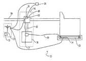
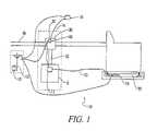
- FIG. 1is a schematic diagram of a water leakage protection apparatus applied to an appliance that uses water.
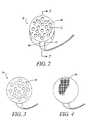
- FIG. 2is a top isometric view of the water ionization switch of the present invention including a container openings that allow for water penetration of the interior of the container.
- FIG. 3is a top view of the water ionization switch of the present invention showing water penetration openings that allow for water penetration of the interior of the container.
- FIG. 4is a top view of an alternative embodiment of the water ionization switch of the present invention showing a water penetration mesh that allows for water penetration of the interior of the container.
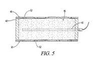
- FIG. 5is a cutaway view of the water ionization switch of FIG. 2 along line A—A showing a container with openings to allow water penetration, an electrode, and a dry non-conductive electrolyte crystallized compound held within the container.
- the water leakage protection apparatus 10includes as major components a low voltage power supply (9v D.C.) 12 , an ionization type water sensor 14 connected to the power supply 12 ; and a controlled valve assembly 16 connected to both the power supply 12 and the ionization type water sensor 14 .
- the water leakage protection apparatus 10can be applied to a single appliance that uses water or can be supplied for multiple applications to protect an entire plumbing system.
- the power supply 12provides a nine-volt DC electrical supply signal for the apparatus 10 .
- the voltage level of the power supply 12 and the associated electrical signalshould be kept as low as possible to reduce any potential shock hazards and the preferred embodiment utilizes a voltage of less than twelve volts DC. This low voltage allows for the safe operation of the water leakage protection apparatus 10 in high humidity or wet environments where high voltage power systems could prove to be harmful or fatal due to electrical shock or creepage.
- the apparatus 10may also utilize a back up battery 13 for continued protection during power outages or brown outs.
- the water ionization switch 14is connected to the power supply 12 and selectively conducts the electrical signal when exposed to water 23 . As shown in FIGS. 2 through 4 , the ionization switch 14 consists of a container 40 , two metallic electrodes 42 , 44 and a dry non-conductive electrolyte crystallized compound 46 .
- the container 40is a two-inch diameter housing manufactured from a non-conductive material.
- the shape of the container 40may be of any configuration including round, square, triangular, ovoid, spherical or any other shape suitable to the application.
- the top cover 48 and bottom cover 50contain openings 52 that allow for water penetration of the interior of the container 40 .
- These openings 52may be formed by utilizing multiple holes in the container 40 , or the openings 52 could be made by using a fine nylon or poly-vinyl-chloride mesh 54 as illustrated in FIG. 4 to allow for water entry.
- FIGS. 1 through 5Also shown in FIGS. 1 through 5 are the mounting of the two electrodes 42 and 44 in the container 40 . These electrodes 42 and 44 are mounted through the side of the housing and are spaced sufficiently apart so as not to make direct electrical contact between the electrodes 42 and 44 .
- the interior of the container 40is filled with a dry crystallized non-conductive electrolyte element 46 as demonstrated in FIG. 5 .
- a dry crystallized non-conductive electrolyte element 46As demonstrated in FIG. 5 .
- the water 23enters the container 40 through the openings 52 , the water 23 comes in contact with the crystallized dry element 46 .
- the water 23then mixes with the dry crystallized electrolyte element 46 and a chemical change, also referred to as an ionization, takes place.
- This ionizationforms an aqueous solution which creates a conductive chemical bridge uniting the two separating electrodes 42 and 44 .
- a moisture level of approximately 40% of the mass of the element 46is required to form the conductive electrolyte.
- the water being absorbed into the element 46forms a conductive path and the chemical switch has been closed.
- the electrolyte compound 46should be non-conductive while in its dry state. However, when water is combined with the dry electrolyte compound, the electrolyte should produce ions which move through the aqueous solution and allow for the electric flow of current through the solution. While water is a poor conductor of electricity, water combined with an electrolyte provides for a good conducting medium.
- a good example of an electrolyteis the chemical compound of sodium chloride (NaCl), commonly referred to as table salt, which is used in the preferred embodiment of the present invention.
- Other solutions of strong electrolytes that are good conductors of electricityare: HCl, and NaOH.
- table saltas an electrolyte compound allows for a sensor that is not dangerous to the environment, is safe around children and pets, and is inexpensive and readily available.
- the use of sodium chloridealso allows for a stable dry composition which allows for the creation of ions and the conductivity of electricity without producing any significant quantity of gasses, acids, or other negative effects.
- large amounts of electricity combined with large quantities of electrolyte, and the particular choices of electrolytesmay produce dangerous quantities or concentrations of gasses, acids, or other secondary effects.
- the resulting chemical reaction componentsshould be accounted for.
- the present inventionuses an electrolyte 46 that is constrained only by the container 40 and does not require a holding or dielectric material. This allows for the container 40 to be filled with an appropriate amount of the crystalline electrolyte 46 such that when the remainder of the volume of the interior of the container 40 is filled with water, a conducting aqueous solution will be formed between the electrodes 42 and 44 . In this manner, the amount of electrolyte 46 is proportionally related to the volume of the interior of the container 40 . This provides an improved sensor 14 with low voltage operating capability.
- the first electrode 42 of the sensor 14is connected to the controlled valve assembly 16 by a cable 20 .
- the second electrode 44is connected to the power supply 12 .
- These electrodes 42 , 44are constructed from standard electrode materials as is well known in the prior art.
- the controlled valve assembly 16is connected to the power supply 12 and the ionization type water sensor 14 .
- the controlled valve assembly 16includes an electric relay 17 connected to a motor 18 which controls a valve 30 .
- the relay 17controls the power flow to the electric motor 18 .
- the electric motor 18is connected by a shaft 32 to the valve 30 for controlling the position of the water valve 30 . Once the motor 18 has moved the valve 30 to a closed position, a closed position switch 31 will be activated to disengaged the power to the motor 18 . In this manner, the assembly 16 has shut off the water supply by closing the valve 30 and will remain inoperative until serviced and reset.
- the system 10controls the valve 30 and shuts off the water supply line 36 .
- the water supply valve 30 used on the stop leak system 10can include an electric motor with a gear type actuated ball valve, an electric motor with type actuated sleeve valve, or an electric solenoid actuated piston valve.
- the preferred embodimentutilizes a ball valve with an actuator assembly.
- a system condition indicator 35may also be included with the system 10 .
- FIG. 1shows an indicator lamp 35 attached to the motor position switch 31 to indicate when the water has been turned off by the system.
- the systemcould also be attached to the ionization switch to indicate the presence of water.
- Other types of indicatorsmay include sound alarms, telephone messages, computer communication, or an interconnection with a home alarms system and its various indication methods.
- the water leakage protection system 10normally rests in a waiting mode and activates only in the detection of water 23 .
- an ion exchangetakes place within the crystallized compound 46 , and it becomes an electrolyte creating a closed circuit between the two separated electrodes 42 and 44 .
- the chemical switch 14is closed allowing for electricity to flow between the electrodes 42 and 44 .
- Thisallows for power to flow from the power supply 12 which causes the relay 17 to close.
- the closing of the relay 17energizes the valve motor 18 and closes the valve 30 .
- the valve 30closes it opens a micro switch 31 disarming the power to the valve 30 .
- the incoming water flow supply 36is stopped and cannot restart without service attention.
- the stop leak valve 30is reopened by pressing a reset button 33 .
- the watercan now flow to the individual appliance or through the entire plumbing system.
Landscapes
- Engineering & Computer Science (AREA)
- Textile Engineering (AREA)
- Water Treatment By Electricity Or Magnetism (AREA)
Abstract
Description
This application claims benefit as a continuation in part of U.S. patent application Ser. No. 09/546,489 filed Apr. 10, 2000 now abandoned entitled “Apparatus and Method for Protection Against Appliance Leaking” which is hereby incorporated by reference.
Be it known that I, John K. Hewitt, a citizen of United States, residing at 2610 Chase Lane, Murfreesboro, Tenn. 37130; Ronald Andrew Cina, a citizen of the United States, residing at 2606 Chase Lane, Murfreesboro, Tenn. 37129; and Ronald August Cina, a citizen of the United States, residing at 1615 Lake Marina Drive, Hixson, Tenn. 37343 have invented a new and useful “Apparatus and Method for Protection Against Appliance Leaking.”
The present invention relates generally to plumbing systems or devices utilizing water connections. More particularly, this invention pertains to general appliances that utilize water connections that are subject to breakage. The invention has utility in applications such as washing machines, water heaters, ice makers, dishwashers and other appliances associated with water overflow or spillage. The application claimed herein is the only system using an ionizing water sensor. All other known or patented devices use systems that are more complex or expensive.
A basic understanding of chemical compositions and electrolytes is helpful in understanding the present invention. Water is an excellent solvent for many compounds. Some compounds dissolve in water as molecules while electrolytes dissociate and dissolve as charged species called ions. Some dissolved compound solutions conduct electricity better than others do, and can be rated on a scaling system. The scaling system includes strong electrolytes, weak electrolytes, and non-electrolytes. These Electrolytes are compounds which dissolve in water to produce solutions that conduct an electric current. A strong electrolyte conducts electricity very well. A weak electrolyte conducts electricity, but not very well. A non-electrolyte does not conduct electricity at all.
Strong electrolytes conduct electricity very well and ionize almost one hundred percent (100%). Most of the salts are in the strong electrolyte category. Examples of strong electrolytes include: HCl, HBr, HI, HNO3, HClO4, H2SO4, HClO3, LiOH, NaOH, KOH, RbOH, CsOH, Ca(OH)2, Sr(OH)2, and Ba(OH)2. There are three common ways in which strong electrolyte conductor can be classified. These are as follows (1) creating an electrolyte by dissolving salts in a solvent by breaking the salt up into its ions; (2) use an acid to give off H+ ions; and (3) use a base to give off OH ions to allow for a good flow of electricity through the solution.
Strong acids are also strong electrolytes. The hydroxides of Groups I and II are considered strong bases and are also strong electrolytes. In addition, most other ionic compounds are strong electrolytes. Generally, the halides and cyanides of “heavy metals” are weak electrolytes and most organic compounds are nonelectrolytes. Some exceptions to he organic compounds are organic acids and bases.
Weak electrolytes conduct electricity a little and are only partially ionized. Most of the acids and bases are in this category. Weak electrolytes include both weak acids and weak bases. A weak acid is much like a strong acid because it produces H+ ions, but the difference is that a weak acid only partially dissociates. Partially dissociating means that only a small percentage of the acid gives off the H+ ions. Weak bases release OH− ions instead of H+ ions.
Non-electrolytes do not conduct electricity and do not ionize. A good example of a non-electrolyte is water. Additional non-Electrolytes are substances that will dissolve in water, but do not produce any ions and therefore do not conduct electricity. For example, sugar will dissolve in water, but will not produce ions. Thus there is nothing to transfer electricity through the solution.
In general, the difference between strong and weak electrolytes is the extent to which the ionic compounds dissociate into ions when placed in water. The greater the amount of dissociation, the greater the electrical conductance of the solution. The strong electrolytes are usually considered to be one hundred percent (100%) dissociated, especially in dilute solutions, and weak electrolytes are usually dissociated less than ten percent (<10%).
This basic chemical information is used in the present invention in combination with a water system. The large majority of commercially feasible water sensors are of the electrical capacitance style detection devices. The devices continuously supply a known low voltage to a pair of electrodes and a return voltage is transmitted back. The return voltage is measured to see if a closed circuit has occurred representing the presence of water. This closed circuit then energizes a horn, light, shut off valve, or a combination of the above. These devices utilize low voltages as a safety feature and thus, these devices can be fooled by varying trace levels of elements in the water, such as calcium and iron. In addition, main power supply fluctuations and electrical noise will also affect the reliability of these devices.
Several United States Patents have been directed towards water detection systems. These patents include U.S. Pat. No. 2,432,367, issued to Anderson on Sep. 23, 1943; U.S. Pat. No. 2,726,294, issued to Kroening, et al on Jan. 30, 1951; U.S. Pat. No. 3,770,002, issued to Brown on Nov. 6, 1973; U.S. Pat. No. 3,847,547, issued to Delgendre, et al on Nov. 12, 1974; U.S. Pat. No. 3,872,419, issued to Groves, et al on Mar. 18, 1975; U.S. Pat. No. 4,163,449, issued to Regal on Aug. 7, 1979; U.S. Pat. No. 4,418,712 issued to Braley on Dec. 6, 1983; U.S. Pat. No. 4,489,603, issued to Fukami, et al on Dec. 25, 1984; U.S. Pat. No. 4,845,472, issued to Gordon on Jul. 4, 1989; U.S. Pat. No. 5,188,143 issued to Krebs on Feb. 23, 1993; U.S. Pat. No. 5,190,069 issued to Richards on Mar. 2, 1993; U.S. Pat. No. 5,240,022 issued to Franklin on Aug. 31, 1993; U.S. Pat. No. 5,334,973, issued to Furr on Aug. 2, 1994; U.S. Pat. No. 5,844,492 issued to Bufflin, Sr. on Dec. 1, 1998; and U.S. Pat. No. 5,877,689 issued to D'Amico on Mar. 2, 1999. The following is a brief discussion of the most relevant of these patents.
U.S. Pat. No. 2,432,367 issued to Anderson on Dec. 9, 1947 discloses a leak detector. This specification discloses the use of a water absorbent material which expands to close the contacts of an electrical circuit for generating a water detection signal. In this specification, it is noted that the electrical contacts should be maintained separately from the absorbent material and the fluid that is to be detected.
U.S. Pat. No. 3,847,547 issued to Delgendre et al. on Nov. 12, 1974, discloses a PROCESS AND APPARATUS FOR DETECTING OF THE PRESENCE OF A LIQUID. This specification describes the use of a chemical reaction, such as a pyrotechnical composition with the absorption of water for closing an electrical circuit. Specifically, the invention teaches the production of heat to generate an electrically conducting deposit in the zone situated between the two electrodes for closing an electrical circuit. The invention also teaches the melting of fusible conducting wire in order to open an electrical circuit. These processes are activated by a chemical reaction when water is introduced into the sensor.
U.S. Pat. No. 4,418,712 issued to Braley on Dec. 6, 1983 discloses an overflow control system for use with appliances such as washing machines. The device has a sensor mechanism that senses any spilled water beneath the machine. Upon water being sensed, electrical circuitry is activated that sounds an alarm and also shuts off the washing machine so that the machine will not continue to pump water through its exit pipe and into the drain stand. This device is designed to avoid problems associated with overflows because of clogging of the drain lines but does not address the need to shut off water coming into the machine.
U.S. Pat. No. 4,489,603 issued to Fukami et al. on Dec. 25, 1984 discloses a moisture sensitive element. In column 1, lines 39–45, this patent specification describes the use of prior art humidity detection systems and references the “ionic conduction through moisture absorption” for humidity sensors. However, as noted by this description of the prior art systems, the prior art units are directed towards humidistats and not switches.
U.S. Pat. No. 5,190,069 issued to Richards on Mar. 2, 1993 discloses a leak detection apparatus for monitoring leakage for household water systems. The system includes a pair of spaced wires imbedded in an insulating tape. The tape can be wrapped about water supply lines and if there is a leakage, the spaced wires will be connected and activate a servo to turn off a supply valve and/or sound an alarm.
U.S. Pat. No. 5,240,022 issued to Franklin on Aug. 31, 1993 discloses an automatic shut off valve system for installation in the water supply line of a hot water heater. The devise includes a sensor to detect leakage electrically by sensing moisture beneath the hot water heater and in response to the sensing of moisture, the device uses a valve system for shutting off the supply line to the hot water heater. The device of this patent is best illustrated inFIG. 2 , showing aleak detection module 17 which activates the shut off valve1 which is activated in response to themodule 17 sensing moisture beneath the hot water heater. The cut off valve1 is inserted in the supply pipe via the pipe fittings2 and3 as can be seen inFIG. 1 .
U.S. Pat. No. 5,334,973 issued to Furr on Aug. 2, 1994 discloses a leak detection and a shut-off apparatus. This patent describes a sensor127 which utilizes a blotter or non-conductive material that becomes conductive when it absorbs moisture. The blotter is contained within a copper skin such that it allows a capacitance current to flow when water is detected.
U.S. Pat. No. 5,877,689 issued to D'Amico on Mar. 2, 1999. The D'Amico patent discloses a system quite similar to that of the Franklin patent. There is shown awater appliance 12 having asupply pipe 14 which allows water to be supplied to the appliance. In this particular case, the appliance is gas powered and has agas supply conduit 16 for transmitting gas from the gas source to the machine. Situated below the water appliance is a water sensor34. When the water sensor34 detects water in the pan beneath the appliance, it is activated to both shut off the water supply to the appliance and shut off the gas supply to the appliance so that the appliance will not burn out once the water is drained from the appliance.
These systems fail to disclose adequate systems for efficient, low-cost water detection systems for household appliances and other water utilizing systems. Therefore, because of the inadequate systems presently used in the prior art an improved water detection system is required. The present system is designed to provide a low-cost, basic, reliable, protection system that is not susceptible to voltage fluctuations or electrical noise and provides an affordable alternative for the consumer.
The present invention is directed towards a water protection system apparatus for detecting and stopping a flow of water which includes a low voltage (9v D.C.) power supply, a water ionization switch, and a controlled valve assembly. The water ionization switch selectively conducts electricity when exposed to water and includes an initially dry non-conductive crystallized compound. The compound ionizes when exposed to water to form an electrolyte which conducts electricity. This switch is connected to a controlled valve assembly to stop the flow of water in response to the detection of water by the switch. Other refinements include modifications to the switch housing and condition indicators for monitoring the system and signaling water detection and shutdown operations.
In accordance with an exemplary embodiment of the present invention as shown inFIG. 1 , the waterleakage protection apparatus 10 includes as major components a low voltage power supply (9v D.C.)12, an ionizationtype water sensor 14 connected to thepower supply 12; and a controlledvalve assembly 16 connected to both thepower supply 12 and the ionizationtype water sensor 14. The waterleakage protection apparatus 10 can be applied to a single appliance that uses water or can be supplied for multiple applications to protect an entire plumbing system.
Thepower supply 12 provides a nine-volt DC electrical supply signal for theapparatus 10. The voltage level of thepower supply 12 and the associated electrical signal should be kept as low as possible to reduce any potential shock hazards and the preferred embodiment utilizes a voltage of less than twelve volts DC. This low voltage allows for the safe operation of the waterleakage protection apparatus 10 in high humidity or wet environments where high voltage power systems could prove to be harmful or fatal due to electrical shock or creepage. Theapparatus 10 may also utilize a back upbattery 13 for continued protection during power outages or brown outs.
Thewater ionization switch 14 is connected to thepower supply 12 and selectively conducts the electrical signal when exposed towater 23. As shown inFIGS. 2 through 4 , theionization switch 14 consists of acontainer 40, twometallic electrodes compound 46.
In the preferred embodiment, thecontainer 40 is a two-inch diameter housing manufactured from a non-conductive material. The shape of thecontainer 40 may be of any configuration including round, square, triangular, ovoid, spherical or any other shape suitable to the application. As shown inFIGS. 2 through 5 , thetop cover 48 and bottom cover50 containopenings 52 that allow for water penetration of the interior of thecontainer 40. Theseopenings 52 may be formed by utilizing multiple holes in thecontainer 40, or theopenings 52 could be made by using a fine nylon or poly-vinyl-chloride mesh 54 as illustrated inFIG. 4 to allow for water entry.
Also shown inFIGS. 1 through 5 are the mounting of the twoelectrodes container 40. Theseelectrodes electrodes
The interior of thecontainer 40 is filled with a dry crystallizednon-conductive electrolyte element 46 as demonstrated inFIG. 5 . Whenwater 23 enters thecontainer 40 through theopenings 52, thewater 23 comes in contact with the crystallizeddry element 46. Thewater 23 then mixes with the drycrystallized electrolyte element 46 and a chemical change, also referred to as an ionization, takes place. This ionization forms an aqueous solution which creates a conductive chemical bridge uniting the two separatingelectrodes element 46 is required to form the conductive electrolyte. Hence, the water being absorbed into theelement 46 forms a conductive path and the chemical switch has been closed.
Theelectrolyte compound 46 should be non-conductive while in its dry state. However, when water is combined with the dry electrolyte compound, the electrolyte should produce ions which move through the aqueous solution and allow for the electric flow of current through the solution. While water is a poor conductor of electricity, water combined with an electrolyte provides for a good conducting medium. A good example of an electrolyte is the chemical compound of sodium chloride (NaCl), commonly referred to as table salt, which is used in the preferred embodiment of the present invention. Other solutions of strong electrolytes that are good conductors of electricity are: HCl, and NaOH.
The use of table salt as an electrolyte compound allows for a sensor that is not dangerous to the environment, is safe around children and pets, and is inexpensive and readily available. The use of sodium chloride also allows for a stable dry composition which allows for the creation of ions and the conductivity of electricity without producing any significant quantity of gasses, acids, or other negative effects. One should remember that large amounts of electricity combined with large quantities of electrolyte, and the particular choices of electrolytes, may produce dangerous quantities or concentrations of gasses, acids, or other secondary effects. Thus, if large switches of this nature are to be used, then the resulting chemical reaction components should be accounted for. These factors are not a problem for the size of the switch and the electrical power used in the preferred embodiment of the present invention. In addition, the availability and non-dangerous aspects of table salt, combined with the stable nature and safe reactions of sodium chloride in the size of switch used in the present application, make sodium chloride the preferred electrolyte compound.
Many electrolyte solutions taught in the prior art use fibers or cellulose material as a dielectric material to carry the electrolyte which results in a significant resistance between the electrodes during both conducting and non-conducting time periods. This leads to a potential drop between the electrodes due to the high resistance and an inability to conduct reasonable operating currents at low voltage levels to eliminate the requirement for weak sensor signals. Thus, prior art designs have consistently used high voltage levels to force current through the electrolyte/dielectric material or have sensed the change in capacitance of the sensor. The present invention overcomes this disadvantage as shown inFIG. 5 by using acontainer 40 to directly contain the sodium chloride type ofelectrolyte 46 without the requirement for the dielectric material. Thus, the present invention uses anelectrolyte 46 that is constrained only by thecontainer 40 and does not require a holding or dielectric material. This allows for thecontainer 40 to be filled with an appropriate amount of thecrystalline electrolyte 46 such that when the remainder of the volume of the interior of thecontainer 40 is filled with water, a conducting aqueous solution will be formed between theelectrodes electrolyte 46 is proportionally related to the volume of the interior of thecontainer 40. This provides animproved sensor 14 with low voltage operating capability.
Thefirst electrode 42 of thesensor 14 is connected to the controlledvalve assembly 16 by acable 20. Thesecond electrode 44 is connected to thepower supply 12. Thus, when the chemical switch closes, power is transferred through the switch to control the controlledvalve assembly 16. Theseelectrodes
The controlledvalve assembly 16 is connected to thepower supply 12 and the ionizationtype water sensor 14. The controlledvalve assembly 16 includes anelectric relay 17 connected to amotor 18 which controls avalve 30. Therelay 17 controls the power flow to theelectric motor 18. Theelectric motor 18 is connected by ashaft 32 to thevalve 30 for controlling the position of thewater valve 30. Once themotor 18 has moved thevalve 30 to a closed position, aclosed position switch 31 will be activated to disengaged the power to themotor 18. In this manner, theassembly 16 has shut off the water supply by closing thevalve 30 and will remain inoperative until serviced and reset. Thus, by energizing thevalve control relay 17, thesystem 10 controls thevalve 30 and shuts off thewater supply line 36.
Thewater supply valve 30 used on thestop leak system 10 can include an electric motor with a gear type actuated ball valve, an electric motor with type actuated sleeve valve, or an electric solenoid actuated piston valve. The preferred embodiment utilizes a ball valve with an actuator assembly.
Asystem condition indicator 35 may also be included with thesystem 10. As an example of thepreferred system indicator 35,FIG. 1 shows anindicator lamp 35 attached to the motor position switch31 to indicate when the water has been turned off by the system. The system could also be attached to the ionization switch to indicate the presence of water. Other types of indicators may include sound alarms, telephone messages, computer communication, or an interconnection with a home alarms system and its various indication methods.
The waterleakage protection system 10 normally rests in a waiting mode and activates only in the detection ofwater 23. Whenwater 23 comes into contact with thesensor 14, an ion exchange takes place within the crystallizedcompound 46, and it becomes an electrolyte creating a closed circuit between the two separatedelectrodes chemical switch 14 is closed allowing for electricity to flow between theelectrodes power supply 12 which causes therelay 17 to close. The closing of therelay 17 energizes thevalve motor 18 and closes thevalve 30. When thevalve 30 closes it opens amicro switch 31 disarming the power to thevalve 30. The incomingwater flow supply 36 is stopped and cannot restart without service attention. After the water leak has been corrected thestop leak valve 30 is reopened by pressing areset button 33. The water can now flow to the individual appliance or through the entire plumbing system.
Thus, although there have been described particular embodiments of the present invention of a new and useful Protection Against Appliance Leaking, it is not intended that such references be construed as limitations upon the scope of this invention except as set forth in the following claims.
Claims (8)
1. A water protection system apparatus for detecting and stopping a flow of water, comprising:
a power supply for generating a direct current electrical signal;
a water ionization switch connected to the power supply, said water ionization switch including a container, wherein the water ionization switch selectively conducts the direct current electrical signal when exposed to water,
the water ionization switch including an initially dry non-conductive crystallized compound constrained only by said container, wherein the compound ionizes to form an electrolyte when combined with water; and
a controlled valve assembly connected to the power supply and the ionization switch, wherein the valve assembly stops the flow of water in response to a change in the direct current electrical signal.
2. The apparatus ofclaim 1 , wherein the electrical signal utilizes a voltage of less than 12 volts as a safety feature for reducing electrical shock hazards.
3. The apparatus ofclaim 1 , the power supply including a main power supply and a backup battery which allows operation of the system during periods of inadequate power from the main power supply.
4. The apparatus ofclaim 1 , said water ionization switch including:
a container with openings to allow for water entry;
a first and second electrodes located within the container and separated by the compound.
5. The apparatus ofclaim 1 , said controlled valve assembly including:
an electric relay connected to the sensor;
a valve actuator connected to the relay;
a reset switch connected between the sensor and the relay.
6. The apparatus ofclaim 5 , said controlled valve assembly further including a reset button connected to said reset switch.
7. The apparatus ofclaim 1 , further comprising:
a condition indicator operatively connected to said ionization switch and said power supply for indicating the operation of said valve assembly.
8. The apparatus ofclaim 7 , wherein said condition indicator includes a light source.
Priority Applications (1)
| Application Number | Priority Date | Filing Date | Title |
|---|---|---|---|
| US10/027,225US6950032B1 (en) | 2000-04-10 | 2001-12-26 | Apparatus and method for protection against appliance leaking |
Applications Claiming Priority (2)
| Application Number | Priority Date | Filing Date | Title |
|---|---|---|---|
| US54648900A | 2000-04-10 | 2000-04-10 | |
| US10/027,225US6950032B1 (en) | 2000-04-10 | 2001-12-26 | Apparatus and method for protection against appliance leaking |
Related Parent Applications (1)
| Application Number | Title | Priority Date | Filing Date |
|---|---|---|---|
| US54648900AContinuation-In-Part | 2000-04-10 | 2000-04-10 |
Publications (1)
| Publication Number | Publication Date |
|---|---|
| US6950032B1true US6950032B1 (en) | 2005-09-27 |
Family
ID=34992649
Family Applications (1)
| Application Number | Title | Priority Date | Filing Date |
|---|---|---|---|
| US10/027,225Expired - Fee RelatedUS6950032B1 (en) | 2000-04-10 | 2001-12-26 | Apparatus and method for protection against appliance leaking |
Country Status (1)
| Country | Link |
|---|---|
| US (1) | US6950032B1 (en) |
Cited By (36)
| Publication number | Priority date | Publication date | Assignee | Title |
|---|---|---|---|---|
| US20040103927A1 (en)* | 2002-11-28 | 2004-06-03 | Ha Jae Hoon | Dishwasher |
| US20040163185A1 (en)* | 2002-12-10 | 2004-08-26 | Geon Kim | Washing machine and control method thereof |
| US20050147402A1 (en)* | 2003-02-19 | 2005-07-07 | Apcom, Inc. | Water heater and method of operating the same |
| US7082959B1 (en)* | 2006-03-21 | 2006-08-01 | Franklin Robert C | Shutoff valve system with leak detector |
| US7124772B1 (en) | 2006-02-24 | 2006-10-24 | Browning David L | Laundry room and appliance mat |
| US20070271935A1 (en)* | 2006-05-23 | 2007-11-29 | Robinson Joe D | Condensate/water leak control switch |
| US7362230B1 (en) | 2007-03-14 | 2008-04-22 | Dan Fish | Leak detection apparatus |
| US20080179962A1 (en)* | 2007-01-11 | 2008-07-31 | Watts Water Technologies, Inc. | Leak detector pad |
| US20090091460A1 (en)* | 2007-10-09 | 2009-04-09 | David Woodrow J | Fluid leak detection system and associated method |
| US20090126465A1 (en)* | 2007-11-16 | 2009-05-21 | Electrolux Home Products, Inc. | Leak detection system for a dishwasher and associated method |
| US20100180956A1 (en)* | 2009-01-21 | 2010-07-22 | Sharp Terry D | Method and systems for detecting and preventing leakage |
| US20110162727A1 (en)* | 2010-01-05 | 2011-07-07 | Norman Thomas Stieb | Leak Detection System for Humidifier |
| US8590559B1 (en)* | 2012-05-23 | 2013-11-26 | Ezequiel Gutierrez | Leak detector assembly |
| US8776824B2 (en)* | 2012-10-19 | 2014-07-15 | Micro Sutures & Golden-Tech Co., Ltd. | Sanitary automatic water leakage detection and shut-off apparatus |
| US20140202558A1 (en)* | 2013-01-18 | 2014-07-24 | Megaflow Corp. | Valve manifold box |
| US20150290567A1 (en)* | 2014-04-10 | 2015-10-15 | General Electric Company | System for detecting a liquid and a water filter assembly |
| CN105627580A (en)* | 2016-03-09 | 2016-06-01 | 广东万家乐燃气具有限公司 | Earth leakage protection system for electric water heater and electric water heater |
| US10018407B2 (en) | 2015-08-25 | 2018-07-10 | Haier Us Appliance Solutions, Inc. | Filter cartridge |
| US10040009B1 (en) | 2017-06-27 | 2018-08-07 | Haier Us Appliance Solutions, Inc. | Filter cartridge |
| US10127790B2 (en) | 2016-03-22 | 2018-11-13 | Watts Regulator Co. | Leak detector |
| US10150067B2 (en) | 2015-09-08 | 2018-12-11 | Haier Us Appliance Solutions, Inc. | Filter cartridge |
| US10161115B2 (en)* | 2016-10-26 | 2018-12-25 | Elexa Consumer Products, Inc. | Water detection and shut-off system and methods |
| US10166495B2 (en) | 2014-04-10 | 2019-01-01 | Haier Us Appliance Solutions, Inc. | Filter cartridge |
| US10173155B2 (en) | 2014-04-10 | 2019-01-08 | Haier Us Appliance Solutions, Inc. | Water filter assembly and a system for detecting liquid |
| US10173904B2 (en) | 2014-04-10 | 2019-01-08 | Haier Us Appliance Solutions, Inc. | System for detecting a liquid and a water filter assembly |
| US10274237B2 (en) | 2017-01-31 | 2019-04-30 | Haier Us Appliance Solutions, Inc. | Ice maker for an appliance |
| US20190243313A1 (en)* | 2014-09-08 | 2019-08-08 | Vision Works Ip Corporation | Indicators for external variables consisting of singular and multiple depletion cells |
| US10391430B2 (en) | 2015-09-21 | 2019-08-27 | Haier Us Appliance Solutions, Inc. | Filter assembly |
| US10502477B2 (en) | 2014-07-28 | 2019-12-10 | Haier Us Appliance Solutions, Inc. | Refrigerator appliance |
| US10571179B2 (en) | 2017-01-26 | 2020-02-25 | Haier Us Appliance Solutions, Inc. | Refrigerator appliance with a clear icemaker |
| US10605493B2 (en) | 2017-01-26 | 2020-03-31 | Haier Us Appliance Solutions, Inc. | Refrigerator appliance with a clear icemaker |
| US11513023B2 (en)* | 2019-11-01 | 2022-11-29 | Andre Auger | System and method for detecting and containing liquid leaks |
| EP4194598A1 (en)* | 2021-12-07 | 2023-06-14 | Whirlpool Corporation | Water leakage management system - sensing on location |
| US11703364B2 (en) | 2018-11-05 | 2023-07-18 | Watts Regulator Co. | Fluid discharge event detector |
| US20230375245A1 (en)* | 2022-05-19 | 2023-11-23 | Haier Us Appliance Solutions, Inc. | Ice maker appliance leak detection |
| EP4407089A3 (en)* | 2023-01-25 | 2024-09-04 | Whirlpool Corporation | Water detection and management system using water leak sensor |
Citations (20)
| Publication number | Priority date | Publication date | Assignee | Title |
|---|---|---|---|---|
| US2432367A (en) | 1943-09-23 | 1947-12-09 | Wingfoot Corp | Leak detector |
| US2726294A (en) | 1951-01-30 | 1955-12-06 | Health Guardian Corp | Devices for giving an alarm upon bed wetting |
| US3200388A (en)* | 1960-08-12 | 1965-08-10 | Weber Aircraft Corp | Water leakage alarm system |
| US3770002A (en)* | 1971-11-01 | 1973-11-06 | L Brown | Automatic water shut-off system |
| US3847547A (en) | 1972-11-24 | 1974-11-12 | France Etat | Process and apparatus for detecting of the presence of a liquid |
| US3872419A (en) | 1972-06-15 | 1975-03-18 | Alexander J Groves | Electrical elements operable as thermisters, varisters, smoke and moisture detectors, and methods for making the same |
| US4163449A (en) | 1977-09-30 | 1979-08-07 | Regal Robert A | Enuresis treatment device |
| US4418712A (en) | 1980-01-16 | 1983-12-06 | Braley Charles A | Overflow control system |
| US4489603A (en) | 1981-09-09 | 1984-12-25 | Nippon Soken, Inc. | Moisture sensitive element |
| US4591838A (en)* | 1983-03-23 | 1986-05-27 | The United States Of America As Represented By The Administrator Of The National Aeronautics And Space Administration | Spillage detector for liquid chromatography systems |
| US4845472A (en) | 1986-11-06 | 1989-07-04 | Hkg Industries, Inc. | Leak sensing alarm and supply shut-off apparatus |
| US4888455A (en)* | 1989-02-27 | 1989-12-19 | Hanson James B | Water leak detector and method therefor |
| US5188143A (en) | 1992-03-09 | 1993-02-23 | Krebs Robert G | Water leakage detection device |
| US5190069A (en) | 1992-04-27 | 1993-03-02 | Richards Raymond C | Apparatus and method for detecting leaks |
| US5240022A (en) | 1991-10-03 | 1993-08-31 | Franklin Robert C | Automatic shutoff valve |
| US5334973A (en) | 1992-02-04 | 1994-08-02 | Furr Mark A | Leak detection and shut-off apparatus |
| US5357241A (en)* | 1991-08-02 | 1994-10-18 | Welch Jr James G | Fail-safe leak detector |
| US5844492A (en) | 1997-10-02 | 1998-12-01 | Buffin, Sr.; John J. | Water leakage detection and gas shut-off device |
| US5877689A (en) | 1997-09-30 | 1999-03-02 | D'amico; Dan | Leak detector |
| US5918617A (en)* | 1997-05-13 | 1999-07-06 | Garth; Barry A. | Method and apparatus for minimizing fluid damage proximate an appliance that uses fluid in its operational cycle |
- 2001
- 2001-12-26USUS10/027,225patent/US6950032B1/ennot_activeExpired - Fee Related
Patent Citations (20)
| Publication number | Priority date | Publication date | Assignee | Title |
|---|---|---|---|---|
| US2432367A (en) | 1943-09-23 | 1947-12-09 | Wingfoot Corp | Leak detector |
| US2726294A (en) | 1951-01-30 | 1955-12-06 | Health Guardian Corp | Devices for giving an alarm upon bed wetting |
| US3200388A (en)* | 1960-08-12 | 1965-08-10 | Weber Aircraft Corp | Water leakage alarm system |
| US3770002A (en)* | 1971-11-01 | 1973-11-06 | L Brown | Automatic water shut-off system |
| US3872419A (en) | 1972-06-15 | 1975-03-18 | Alexander J Groves | Electrical elements operable as thermisters, varisters, smoke and moisture detectors, and methods for making the same |
| US3847547A (en) | 1972-11-24 | 1974-11-12 | France Etat | Process and apparatus for detecting of the presence of a liquid |
| US4163449A (en) | 1977-09-30 | 1979-08-07 | Regal Robert A | Enuresis treatment device |
| US4418712A (en) | 1980-01-16 | 1983-12-06 | Braley Charles A | Overflow control system |
| US4489603A (en) | 1981-09-09 | 1984-12-25 | Nippon Soken, Inc. | Moisture sensitive element |
| US4591838A (en)* | 1983-03-23 | 1986-05-27 | The United States Of America As Represented By The Administrator Of The National Aeronautics And Space Administration | Spillage detector for liquid chromatography systems |
| US4845472A (en) | 1986-11-06 | 1989-07-04 | Hkg Industries, Inc. | Leak sensing alarm and supply shut-off apparatus |
| US4888455A (en)* | 1989-02-27 | 1989-12-19 | Hanson James B | Water leak detector and method therefor |
| US5357241A (en)* | 1991-08-02 | 1994-10-18 | Welch Jr James G | Fail-safe leak detector |
| US5240022A (en) | 1991-10-03 | 1993-08-31 | Franklin Robert C | Automatic shutoff valve |
| US5334973A (en) | 1992-02-04 | 1994-08-02 | Furr Mark A | Leak detection and shut-off apparatus |
| US5188143A (en) | 1992-03-09 | 1993-02-23 | Krebs Robert G | Water leakage detection device |
| US5190069A (en) | 1992-04-27 | 1993-03-02 | Richards Raymond C | Apparatus and method for detecting leaks |
| US5918617A (en)* | 1997-05-13 | 1999-07-06 | Garth; Barry A. | Method and apparatus for minimizing fluid damage proximate an appliance that uses fluid in its operational cycle |
| US5877689A (en) | 1997-09-30 | 1999-03-02 | D'amico; Dan | Leak detector |
| US5844492A (en) | 1997-10-02 | 1998-12-01 | Buffin, Sr.; John J. | Water leakage detection and gas shut-off device |
Cited By (50)
| Publication number | Priority date | Publication date | Assignee | Title |
|---|---|---|---|---|
| US20040103927A1 (en)* | 2002-11-28 | 2004-06-03 | Ha Jae Hoon | Dishwasher |
| US7360545B2 (en)* | 2002-11-28 | 2008-04-22 | Lg Electronics Inc. | Dishwasher |
| US20040163185A1 (en)* | 2002-12-10 | 2004-08-26 | Geon Kim | Washing machine and control method thereof |
| US20050147402A1 (en)* | 2003-02-19 | 2005-07-07 | Apcom, Inc. | Water heater and method of operating the same |
| US7373080B2 (en)* | 2003-02-19 | 2008-05-13 | Apcom, Inc. | Water heater and method of operating the same |
| US7124772B1 (en) | 2006-02-24 | 2006-10-24 | Browning David L | Laundry room and appliance mat |
| US7082959B1 (en)* | 2006-03-21 | 2006-08-01 | Franklin Robert C | Shutoff valve system with leak detector |
| US20070271935A1 (en)* | 2006-05-23 | 2007-11-29 | Robinson Joe D | Condensate/water leak control switch |
| US20100101252A1 (en)* | 2006-05-23 | 2010-04-29 | Robinson Joe D | Condensate/water leak control switch |
| US8333082B2 (en) | 2006-05-23 | 2012-12-18 | Robinson Joe D | Condensate/water leak control switch |
| US7640759B2 (en) | 2006-05-23 | 2010-01-05 | Robinson Joe D | Condensate/water leak control switch |
| US20080179962A1 (en)* | 2007-01-11 | 2008-07-31 | Watts Water Technologies, Inc. | Leak detector pad |
| US7753071B2 (en)* | 2007-01-11 | 2010-07-13 | Altos Limited LC | Leak detector pad |
| US7362230B1 (en) | 2007-03-14 | 2008-04-22 | Dan Fish | Leak detection apparatus |
| US7696889B2 (en) | 2007-10-09 | 2010-04-13 | David Woodrow J | Fluid leak detection system and associated method |
| US20090091460A1 (en)* | 2007-10-09 | 2009-04-09 | David Woodrow J | Fluid leak detection system and associated method |
| US20090126465A1 (en)* | 2007-11-16 | 2009-05-21 | Electrolux Home Products, Inc. | Leak detection system for a dishwasher and associated method |
| US20100180956A1 (en)* | 2009-01-21 | 2010-07-22 | Sharp Terry D | Method and systems for detecting and preventing leakage |
| US7926504B2 (en)* | 2009-01-21 | 2011-04-19 | Sharp Technologies, Inc. | Method and systems for detecting and preventing leakage |
| US20110162727A1 (en)* | 2010-01-05 | 2011-07-07 | Norman Thomas Stieb | Leak Detection System for Humidifier |
| US8430115B2 (en)* | 2010-01-05 | 2013-04-30 | Norman Thomas Stieb | Leak detection system for humidifier |
| US8590559B1 (en)* | 2012-05-23 | 2013-11-26 | Ezequiel Gutierrez | Leak detector assembly |
| US8776824B2 (en)* | 2012-10-19 | 2014-07-15 | Micro Sutures & Golden-Tech Co., Ltd. | Sanitary automatic water leakage detection and shut-off apparatus |
| US20140202558A1 (en)* | 2013-01-18 | 2014-07-24 | Megaflow Corp. | Valve manifold box |
| US20150290567A1 (en)* | 2014-04-10 | 2015-10-15 | General Electric Company | System for detecting a liquid and a water filter assembly |
| US10166495B2 (en) | 2014-04-10 | 2019-01-01 | Haier Us Appliance Solutions, Inc. | Filter cartridge |
| US10173155B2 (en) | 2014-04-10 | 2019-01-08 | Haier Us Appliance Solutions, Inc. | Water filter assembly and a system for detecting liquid |
| US10173904B2 (en) | 2014-04-10 | 2019-01-08 | Haier Us Appliance Solutions, Inc. | System for detecting a liquid and a water filter assembly |
| US10173905B2 (en)* | 2014-04-10 | 2019-01-08 | Haier Us Appliance Solutions, Inc. | System for detecting a liquid and a water filter assembly |
| US10502477B2 (en) | 2014-07-28 | 2019-12-10 | Haier Us Appliance Solutions, Inc. | Refrigerator appliance |
| US20190243313A1 (en)* | 2014-09-08 | 2019-08-08 | Vision Works Ip Corporation | Indicators for external variables consisting of singular and multiple depletion cells |
| US10018407B2 (en) | 2015-08-25 | 2018-07-10 | Haier Us Appliance Solutions, Inc. | Filter cartridge |
| US10150067B2 (en) | 2015-09-08 | 2018-12-11 | Haier Us Appliance Solutions, Inc. | Filter cartridge |
| US10391430B2 (en) | 2015-09-21 | 2019-08-27 | Haier Us Appliance Solutions, Inc. | Filter assembly |
| CN105627580B (en)* | 2016-03-09 | 2019-06-07 | 广东万家乐燃气具有限公司 | A kind of electric water heater leakage protection system and electric heater |
| CN105627580A (en)* | 2016-03-09 | 2016-06-01 | 广东万家乐燃气具有限公司 | Earth leakage protection system for electric water heater and electric water heater |
| US10373471B2 (en) | 2016-03-22 | 2019-08-06 | Watts Regulator Co. | Leak detector |
| US10127790B2 (en) | 2016-03-22 | 2018-11-13 | Watts Regulator Co. | Leak detector |
| US10161115B2 (en)* | 2016-10-26 | 2018-12-25 | Elexa Consumer Products, Inc. | Water detection and shut-off system and methods |
| US10584467B2 (en) | 2016-10-26 | 2020-03-10 | Elexa Consumer Products, Inc. | Water detection and shut-off system and methods |
| US10605493B2 (en) | 2017-01-26 | 2020-03-31 | Haier Us Appliance Solutions, Inc. | Refrigerator appliance with a clear icemaker |
| US10571179B2 (en) | 2017-01-26 | 2020-02-25 | Haier Us Appliance Solutions, Inc. | Refrigerator appliance with a clear icemaker |
| US10274237B2 (en) | 2017-01-31 | 2019-04-30 | Haier Us Appliance Solutions, Inc. | Ice maker for an appliance |
| US10040009B1 (en) | 2017-06-27 | 2018-08-07 | Haier Us Appliance Solutions, Inc. | Filter cartridge |
| US11703364B2 (en) | 2018-11-05 | 2023-07-18 | Watts Regulator Co. | Fluid discharge event detector |
| US12379236B2 (en) | 2018-11-05 | 2025-08-05 | Watts Regulator Co. | Temperature and pressure relief valve |
| US11513023B2 (en)* | 2019-11-01 | 2022-11-29 | Andre Auger | System and method for detecting and containing liquid leaks |
| EP4194598A1 (en)* | 2021-12-07 | 2023-06-14 | Whirlpool Corporation | Water leakage management system - sensing on location |
| US20230375245A1 (en)* | 2022-05-19 | 2023-11-23 | Haier Us Appliance Solutions, Inc. | Ice maker appliance leak detection |
| EP4407089A3 (en)* | 2023-01-25 | 2024-09-04 | Whirlpool Corporation | Water detection and management system using water leak sensor |
Similar Documents
| Publication | Publication Date | Title |
|---|---|---|
| US6950032B1 (en) | Apparatus and method for protection against appliance leaking | |
| US9799201B2 (en) | Water heater leak detection system | |
| US4305420A (en) | Automatic water or liquid safety valve assembly | |
| US5793294A (en) | Sump alarm | |
| CA2292901C (en) | Oil or water leak detector/alarm system | |
| US4491146A (en) | Liquid level control | |
| US5008650A (en) | Leak damage prevention system | |
| US3461446A (en) | Fluid-level detecting apparatus | |
| JPS6035613B2 (en) | Liquid level indicator | |
| WO2000014456A8 (en) | Control system for bathers | |
| EP0757008B1 (en) | Tank container with deflector | |
| US5153564A (en) | Leak damage prevention system | |
| US7649468B2 (en) | System for detecting an undesirable condition and manipulating an electronic device | |
| US4841282A (en) | Smoke and liquid alarm | |
| US20080252447A1 (en) | Combination smoke and water detector | |
| GB2186722A (en) | Detecting leakage of liquid from machines | |
| US5132669A (en) | Level sensor with alarm | |
| CN111399064A (en) | Liquid leakage detection system and method | |
| US4973950A (en) | Sewer blockage alarm | |
| RU2382148C2 (en) | System for monitoring rooms during flooding | |
| US20050051213A1 (en) | Water- and vibration-sensing protection apparatus | |
| JPS6212460B2 (en) | ||
| KR102622228B1 (en) | A heater for heating water that a temperature control switch and a fuse are installed in a stainless steel tube | |
| JP2002013963A (en) | Electrode type liquid level indicator | |
| US5041816A (en) | Freezer alarm system with two sensor models |
Legal Events
| Date | Code | Title | Description |
|---|---|---|---|
| AS | Assignment | Owner name:DRY SYSTEMS, INC., TENNESSEE Free format text:ASSIGNMENT OF ASSIGNORS INTEREST;ASSIGNOR:HEWITT, JOHN K.;REEL/FRAME:016611/0013 Effective date:20050525 | |
| AS | Assignment | Owner name:STAY DRY INTERNATIONAL, LLC, TENNESSEE Free format text:ASSIGNMENT OF ASSIGNORS INTEREST;ASSIGNOR:DRY SYSTEMS, INC.;REEL/FRAME:017636/0790 Effective date:20060516 | |
| FPAY | Fee payment | Year of fee payment:4 | |
| REMI | Maintenance fee reminder mailed | ||
| FPAY | Fee payment | Year of fee payment:8 | |
| SULP | Surcharge for late payment | Year of fee payment:7 | |
| REMI | Maintenance fee reminder mailed | ||
| LAPS | Lapse for failure to pay maintenance fees | Free format text:PATENT EXPIRED FOR FAILURE TO PAY MAINTENANCE FEES (ORIGINAL EVENT CODE: EXP.) | |
| STCH | Information on status: patent discontinuation | Free format text:PATENT EXPIRED DUE TO NONPAYMENT OF MAINTENANCE FEES UNDER 37 CFR 1.362 | |
| FP | Lapsed due to failure to pay maintenance fee | Effective date:20170927 |