US6949929B2 - Magnetic resonance imaging interference immune device - Google Patents
Magnetic resonance imaging interference immune deviceDownload PDFInfo
- Publication number
- US6949929B2 US6949929B2US10/780,261US78026104AUS6949929B2US 6949929 B2US6949929 B2US 6949929B2US 78026104 AUS78026104 AUS 78026104AUS 6949929 B2US6949929 B2US 6949929B2
- Authority
- US
- United States
- Prior art keywords
- mri
- induced
- compensation unit
- voltage compensation
- voltages
- Prior art date
- Legal status (The legal status is an assumption and is not a legal conclusion. Google has not performed a legal analysis and makes no representation as to the accuracy of the status listed.)
- Expired - Fee Related
Links
- 238000002595magnetic resonance imagingMethods0.000titleclaimsdescription489
- 230000000694effectsEffects0.000claimsabstractdescription94
- 230000000153supplemental effectEffects0.000claimsabstractdescription8
- 238000004891communicationMethods0.000claimsdescription49
- 239000003990capacitorSubstances0.000claimsdescription27
- 239000013307optical fiberSubstances0.000claimsdescription5
- 230000008859changeEffects0.000claimsdescription3
- 238000001208nuclear magnetic resonance pulse sequenceMethods0.000claims4
- 210000001519tissueAnatomy0.000description53
- 230000004044responseEffects0.000description28
- 230000001939inductive effectEffects0.000description27
- 238000000576coating methodMethods0.000description26
- 239000011248coating agentSubstances0.000description17
- 239000000463materialSubstances0.000description16
- 230000000638stimulationEffects0.000description14
- 238000000034methodMethods0.000description13
- RYGMFSIKBFXOCR-UHFFFAOYSA-NCopperChemical compound[Cu]RYGMFSIKBFXOCR-UHFFFAOYSA-N0.000description12
- 238000004804windingMethods0.000description12
- 230000000747cardiac effectEffects0.000description11
- 239000004020conductorSubstances0.000description9
- 238000003384imaging methodMethods0.000description9
- 230000006378damageEffects0.000description7
- 238000010438heat treatmentMethods0.000description7
- 239000011889copper foilSubstances0.000description6
- 239000002184metalSubstances0.000description6
- 229910052751metalInorganic materials0.000description6
- 230000004962physiological conditionEffects0.000description6
- 230000007246mechanismEffects0.000description5
- 208000027418Wounds and injuryDiseases0.000description4
- 238000010586diagramMethods0.000description4
- 208000014674injuryDiseases0.000description4
- 230000008569processEffects0.000description4
- 229910000859α-FeInorganic materials0.000description4
- 230000003287optical effectEffects0.000description3
- 208000006218bradycardiaDiseases0.000description2
- 230000036471bradycardiaEffects0.000description2
- 230000008878couplingEffects0.000description2
- 238000010168coupling processMethods0.000description2
- 238000005859coupling reactionMethods0.000description2
- 238000013461designMethods0.000description2
- 230000009977dual effectEffects0.000description2
- 230000005672electromagnetic fieldEffects0.000description2
- 238000001914filtrationMethods0.000description2
- 239000011810insulating materialSubstances0.000description2
- NOESYZHRGYRDHS-UHFFFAOYSA-NinsulinChemical compoundN1C(=O)C(NC(=O)C(CCC(N)=O)NC(=O)C(CCC(O)=O)NC(=O)C(C(C)C)NC(=O)C(NC(=O)CN)C(C)CC)CSSCC(C(NC(CO)C(=O)NC(CC(C)C)C(=O)NC(CC=2C=CC(O)=CC=2)C(=O)NC(CCC(N)=O)C(=O)NC(CC(C)C)C(=O)NC(CCC(O)=O)C(=O)NC(CC(N)=O)C(=O)NC(CC=2C=CC(O)=CC=2)C(=O)NC(CSSCC(NC(=O)C(C(C)C)NC(=O)C(CC(C)C)NC(=O)C(CC=2C=CC(O)=CC=2)NC(=O)C(CC(C)C)NC(=O)C(C)NC(=O)C(CCC(O)=O)NC(=O)C(C(C)C)NC(=O)C(CC(C)C)NC(=O)C(CC=2NC=NC=2)NC(=O)C(CO)NC(=O)CNC2=O)C(=O)NCC(=O)NC(CCC(O)=O)C(=O)NC(CCCNC(N)=N)C(=O)NCC(=O)NC(CC=3C=CC=CC=3)C(=O)NC(CC=3C=CC=CC=3)C(=O)NC(CC=3C=CC(O)=CC=3)C(=O)NC(C(C)O)C(=O)N3C(CCC3)C(=O)NC(CCCCN)C(=O)NC(C)C(O)=O)C(=O)NC(CC(N)=O)C(O)=O)=O)NC(=O)C(C(C)CC)NC(=O)C(CO)NC(=O)C(C(C)O)NC(=O)C1CSSCC2NC(=O)C(CC(C)C)NC(=O)C(NC(=O)C(CCC(N)=O)NC(=O)C(CC(N)=O)NC(=O)C(NC(=O)C(N)CC=1C=CC=CC=1)C(C)C)CC1=CN=CN1NOESYZHRGYRDHS-UHFFFAOYSA-N0.000description2
- 238000004519manufacturing processMethods0.000description2
- 238000012986modificationMethods0.000description2
- 230000004048modificationEffects0.000description2
- 230000004936stimulating effectEffects0.000description2
- 102000004877InsulinHuman genes0.000description1
- 108090001061InsulinProteins0.000description1
- 206010049447TachyarrhythmiaDiseases0.000description1
- 208000001871TachycardiaDiseases0.000description1
- 230000002411adverseEffects0.000description1
- 210000003484anatomyAnatomy0.000description1
- 238000013459approachMethods0.000description1
- 206010003119arrhythmiaDiseases0.000description1
- 230000006793arrhythmiaEffects0.000description1
- 230000003190augmentative effectEffects0.000description1
- 239000012472biological sampleSubstances0.000description1
- 230000003683cardiac damageEffects0.000description1
- 239000000919ceramicSubstances0.000description1
- 239000011247coating layerSubstances0.000description1
- 230000007423decreaseEffects0.000description1
- 230000003247decreasing effectEffects0.000description1
- 238000001514detection methodMethods0.000description1
- 208000037265diseases, disorders, signs and symptomsDiseases0.000description1
- 208000035475disorderDiseases0.000description1
- 230000008030eliminationEffects0.000description1
- 238000003379elimination reactionMethods0.000description1
- 230000007613environmental effectEffects0.000description1
- 230000005284excitationEffects0.000description1
- 239000000835fiberSubstances0.000description1
- 239000012530fluidSubstances0.000description1
- 230000005714functional activityEffects0.000description1
- 239000011521glassSubstances0.000description1
- 230000036541healthEffects0.000description1
- 230000001771impaired effectEffects0.000description1
- 239000007943implantSubstances0.000description1
- 238000000338in vitroMethods0.000description1
- 229940125396insulinDrugs0.000description1
- 239000010410layerSubstances0.000description1
- 210000004165myocardiumAnatomy0.000description1
- 210000005036nerveAnatomy0.000description1
- 230000007935neutral effectEffects0.000description1
- 239000012811non-conductive materialSubstances0.000description1
- 210000000056organAnatomy0.000description1
- 230000036278prepulseEffects0.000description1
- 238000012545processingMethods0.000description1
- 230000001902propagating effectEffects0.000description1
- 238000011084recoveryMethods0.000description1
- 230000009467reductionEffects0.000description1
- 230000001020rhythmical effectEffects0.000description1
- 239000000523sampleSubstances0.000description1
- 238000000926separation methodMethods0.000description1
Images


Classifications
- A—HUMAN NECESSITIES
- A61—MEDICAL OR VETERINARY SCIENCE; HYGIENE
- A61N—ELECTROTHERAPY; MAGNETOTHERAPY; RADIATION THERAPY; ULTRASOUND THERAPY
- A61N1/00—Electrotherapy; Circuits therefor
- A61N1/18—Applying electric currents by contact electrodes
- A61N1/32—Applying electric currents by contact electrodes alternating or intermittent currents
- A61N1/36—Applying electric currents by contact electrodes alternating or intermittent currents for stimulation
- A61N1/362—Heart stimulators
- A61N1/37—Monitoring; Protecting
- A—HUMAN NECESSITIES
- A61—MEDICAL OR VETERINARY SCIENCE; HYGIENE
- A61N—ELECTROTHERAPY; MAGNETOTHERAPY; RADIATION THERAPY; ULTRASOUND THERAPY
- A61N1/00—Electrotherapy; Circuits therefor
- A61N1/02—Details
- A61N1/04—Electrodes
- A61N1/05—Electrodes for implantation or insertion into the body, e.g. heart electrode
- G—PHYSICS
- G01—MEASURING; TESTING
- G01R—MEASURING ELECTRIC VARIABLES; MEASURING MAGNETIC VARIABLES
- G01R33/00—Arrangements or instruments for measuring magnetic variables
- G01R33/20—Arrangements or instruments for measuring magnetic variables involving magnetic resonance
- G01R33/28—Details of apparatus provided for in groups G01R33/44 - G01R33/64
- G01R33/285—Invasive instruments, e.g. catheters or biopsy needles, specially adapted for tracking, guiding or visualization by NMR
- G—PHYSICS
- G01—MEASURING; TESTING
- G01R—MEASURING ELECTRIC VARIABLES; MEASURING MAGNETIC VARIABLES
- G01R33/00—Arrangements or instruments for measuring magnetic variables
- G01R33/20—Arrangements or instruments for measuring magnetic variables involving magnetic resonance
- G01R33/28—Details of apparatus provided for in groups G01R33/44 - G01R33/64
- G01R33/32—Excitation or detection systems, e.g. using radio frequency signals
- G01R33/34—Constructional details, e.g. resonators, specially adapted to MR
- G01R33/34084—Constructional details, e.g. resonators, specially adapted to MR implantable coils or coils being geometrically adaptable to the sample, e.g. flexible coils or coils comprising mutually movable parts
- H—ELECTRICITY
- H03—ELECTRONIC CIRCUITRY
- H03H—IMPEDANCE NETWORKS, e.g. RESONANT CIRCUITS; RESONATORS
- H03H7/00—Multiple-port networks comprising only passive electrical elements as network components
- H03H7/42—Networks for transforming balanced signals into unbalanced signals and vice versa, e.g. baluns
- A—HUMAN NECESSITIES
- A61—MEDICAL OR VETERINARY SCIENCE; HYGIENE
- A61B—DIAGNOSIS; SURGERY; IDENTIFICATION
- A61B2562/00—Details of sensors; Constructional details of sensor housings or probes; Accessories for sensors
- A61B2562/22—Arrangements of medical sensors with cables or leads; Connectors or couplings specifically adapted for medical sensors
- A61B2562/221—Arrangements of sensors with cables or leads, e.g. cable harnesses
- A61B2562/222—Electrical cables or leads therefor, e.g. coaxial cables or ribbon cables
- A—HUMAN NECESSITIES
- A61—MEDICAL OR VETERINARY SCIENCE; HYGIENE
- A61N—ELECTROTHERAPY; MAGNETOTHERAPY; RADIATION THERAPY; ULTRASOUND THERAPY
- A61N1/00—Electrotherapy; Circuits therefor
- A61N1/02—Details
- A61N1/08—Arrangements or circuits for monitoring, protecting, controlling or indicating
- A61N1/086—Magnetic resonance imaging [MRI] compatible leads
- A—HUMAN NECESSITIES
- A61—MEDICAL OR VETERINARY SCIENCE; HYGIENE
- A61N—ELECTROTHERAPY; MAGNETOTHERAPY; RADIATION THERAPY; ULTRASOUND THERAPY
- A61N1/00—Electrotherapy; Circuits therefor
- A61N1/18—Applying electric currents by contact electrodes
- A61N1/32—Applying electric currents by contact electrodes alternating or intermittent currents
- A61N1/36—Applying electric currents by contact electrodes alternating or intermittent currents for stimulation
- A61N1/362—Heart stimulators
- A61N1/37—Monitoring; Protecting
- A61N1/3718—Monitoring of or protection against external electromagnetic fields or currents
- G—PHYSICS
- G01—MEASURING; TESTING
- G01R—MEASURING ELECTRIC VARIABLES; MEASURING MAGNETIC VARIABLES
- G01R33/00—Arrangements or instruments for measuring magnetic variables
- G01R33/20—Arrangements or instruments for measuring magnetic variables involving magnetic resonance
- G01R33/28—Details of apparatus provided for in groups G01R33/44 - G01R33/64
- G01R33/288—Provisions within MR facilities for enhancing safety during MR, e.g. reduction of the specific absorption rate [SAR], detection of ferromagnetic objects in the scanner room
Definitions
- the present inventionis directed to a device for protecting a patient, physician, and/or electronic components in an electrical device implanted or partially implanted within the patient. More particularly, the present invention is directed to a device for protecting the conductive parts of the electrical device from current and voltage surges induced by magnetic resonance imaging systems'oscillating magnetic fields.
- Magnetic resonance imaging(“MRI”) has been developed as an imaging technique adapted to obtain both images of anatomical features of human patients as well as some aspects of the functional activities and characteristics of biological tissue. These images have medical diagnostic value in determining the state of the health of the tissue examined. Unlike the situation with fluoroscopic imaging, a patient undergoing magnetic resonance imaging procedure may remain in the active imaging system for a significant amount of time, e.g. a half-hour or more, without suffering any adverse effects.
- a patientis typically aligned to place the portion of the patient's anatomy to be examined in the imaging volume of the MRI apparatus.
- Such an MRI apparatustypically comprises a primary electromagnet for supplying a constant magnetic field (B 0 ) which, by convention, is along the z-axis and is substantially homogeneous over the imaging volume and secondary electromagnets that can provide linear magnetic field gradients along each of three principal Cartesian axes in space (generally x, y, and z, or x 1 , x 2 and x 3 , respectively).
- the MRI apparatusalso comprises one or more radio frequency coils that provide excitation and detection of the MRI induced signals in the patient's body.
- the frequency that a gradient field may be turned ONcan be between 200 Hz to about 300 kHz.
- EMFelectro-motive-force
- a switched gradient fieldin all 3 coordinate directions (x-, y-, z-directions). If the patient has an implanted heart pacemaker (or other implanted devices having conductive components) the switched gradient magnetic fields (an alternating magnetic field) may cause:
- implantable devicessuch as implantable pulse generators (IPGs) and cardioverter/defibrillator/pacemakers (CDPs)
- IPGsimplantable pulse generators
- CDPscardioverter/defibrillator/pacemakers
- EMIelectromagnetic interference
- the sensing systems and conductive elements of these implantable devicesare responsive to changes in local electromagnetic fields, the implanted devices are vulnerable to external sources of severe electromagnetic noise, and in particular, to electromagnetic fields emitted during the magnetic resonance imaging (MRI) procedure.
- MRImagnetic resonance imaging
- bradycardiaoccurs when the heart beats too slowly, and may be treated by a common implantable pacemaker delivering low voltage (about 3 V) pacing pulses.
- the common implantable pacemakeris usually contained within a hermetically sealed enclosure, in order to protect the operational components of the device from the harsh environment of the body, as well as to protect the body from the device.
- the common implantable pacemakeroperates in conjunction with one or more electrically conductive leads, adapted to conduct electrical stimulating pulses to sites within the patient's heart, and to communicate sensed signals from those sites back to the implanted device.
- the common implantable pacemakertypically has a metal case and a connector block mounted to the metal case that includes receptacles for leads which may be used for electrical stimulation or which may be used for sensing of physiological signals.
- the battery and the circuitry associated with the common implantable pacemakerare hermetically sealed within the case. Electrical interfaces are employed to connect the leads outside the metal case with the medical device circuitry and the battery inside the metal case.
- Electrical interfacesserve the purpose of providing an electrical circuit path extending from the interior of a hermetically sealed metal case to an external point outside the case while maintaining the hermetic seal of the case.
- a conductive pathis provided through the interface by a conductive pin that is electrically insulated from the case itself.
- Such interfacestypically include a ferrule that permits attachment of the interface to the case, the conductive pin, and a hermetic glass or ceramic seal that supports the pin within the ferrule and isolates the pin from the metal case.
- a common implantable pacemakercan, under some circumstances, be susceptible to electrical interference such that the desired functionality of the pacemaker is impaired.
- common implantable pacemakerrequires protection against electrical interference from electromagnetic interference (EMI), defibrillation pulses, electrostatic discharge, or other generally large voltages or currents generated by other devices external to the medical device.
- EMIelectromagnetic interference
- defibrillation pulseselectrostatic discharge
- electrostatic dischargeor other generally large voltages or currents generated by other devices external to the medical device.
- cardiac assist systemsbe protected from magnetic-resonance imaging sources.
- Such electrical interferencecan damage the circuitry of the cardiac assist systems or cause interference in the proper operation or functionality of the cardiac assist systems. For example, damage may occur due to high voltages or excessive currents introduced into the cardiac assist system.
- a medical device or systemthat reduces or eliminates the undesirable effects of changing magnetic fields from an MRI system on the medical devices and/or patients undergoing medical procedures or that have temporary or permanent implanted materials and/or devices with conducting components.
- a first aspect of the present inventionis a voltage compensation unit for reducing the effects of induced voltages upon a device to a safe level.
- the voltage compensation unitincludes a sensing circuit to sense voltages induced in conductive components of the device, the voltages being induced by changing magnetic fields and a compensation circuit, operatively connected to the sensing circuit and responsive thereto, to provide opposing voltages to the device to reduce the effects of induced voltages caused by changing magnetic fields.
- a second aspect of the present inventionis a voltage compensation unit for reducing the effects of induced voltages upon a tissue invasive medical tool to a safe level.
- the voltage compensation unitincludes a sensing circuit to sense voltages induced in conductive components of the medical tool, the voltages being induced by changing magnetic fields; a compensation circuit, operatively connected to the sensing circuit and responsive thereto, to provide opposing voltages to the medical tool to reduce the effects of induced voltages caused by changing magnetic fields; and a connection device to provide an electrical connection between the sensing circuit and the compensation circuit and the medical tool.
- a third aspect of the present inventionis a voltage compensation unit for reducing the effects of induced voltages upon a device to a safe level.
- the voltage compensation unitincludes a communication circuit, communicatively linked to a MRI system, to receive information associated with a start and end of an application of changing magnetic fields produced by the MRI system and a compensation circuit, operatively connected to the communication circuit and responsive thereto, to synchronize application of opposing voltages to the device with the sensed changing magnetic fields, the opposing voltages reducing the effects of induced voltages caused by the changing magnetic fields.
- a fourth aspect of the present inventionis a voltage compensation unit for reducing the effects of induced voltages upon a device to a safe level.
- the voltage compensation unitincludes a communication circuit, communicatively linked to a MRI system, to receive information associated with a start and end of an application of changing magnetic fields produced by the MRI system and a compensation circuit, operatively connected to the communication circuit and responsive thereto, to apply opposing voltages to the device, the opposing voltages reducing the effects of induced voltages caused by the changing magnetic fields.
- a fifth aspect of the present inventionis a voltage compensation unit for reducing the effects of induced voltages upon a device having a single wire line, the single wire line having a balanced characteristic impedance.
- the voltage compensation unitincludes a tunable compensation circuit, operatively connected to the wire line, to apply supplemental impedance to the wire line, the supplemental impedance causing the characteristic impedance of the wire line to become unbalanced, thereby reducing the effects of induced voltages caused by changing magnetic fields.
- the systemincludes a medical device wherein the medical device has a housing having electronic circuitry therein, a first lead to provide an electrical path for a stimulation signal generated by the electronic circuitry to be applied to a desired tissue region, a second lead to provide an electrical path for a sensed physiological condition of the desired tissue region to be communicated to the electronic circuitry, and a third lead to provide an electrical ground.
- the systemalso includes a diode, operatively connected to the first lead, to significantly reduce MRI induced signals from traveling along the first lead to the electronic circuitry.
- a further aspect of the present inventionis a system for reducing the effects of MRI induced signals to a safe level.
- the systemincludes a MRI system; a medical device; and a transceiver to provide communication between the MRI system and the medical device.
- the medical devicehas a housing having electronic circuitry therein, a bi-directional lead to provide an electrical path for a stimulation signal generated by the electronic circuitry to be applied to a desired tissue region and to provide an electrical path for a sensed physiological condition of the desired tissue region to be communicated to the electronic circuitry, and a lead to provide an electrical ground.
- the medical deviceindicates to the MRI system, through the transceiver, when the stimulation signal will be applied to the desired tissue region.
- the MRI systemin response to the indication from the medical device of when the stimulation signal will be applied to the desired tissue region, terminates a production of MRI switched gradient fields.
- a further aspect of the present inventionis a system for reducing the effects of MRI induced signals to a safe level.
- the systemincludes a medical device wherein the medical device has a housing having electronic circuitry therein, and leads to provide an electrical path for a stimulation signal generated by the electronic circuitry to be applied to a desired tissue region and to provide an electrical path for a sensed physiological condition of the desired tissue region to be communicated to the electronic circuitry, a sensor to sense application of switched MRI gradient fields, and an electronic component, operatively connected to the leads, to significantly reduce MRI induced signals from traveling along the leads to the electronic circuitry, and a switch, operatively connected to the sensor and the electronic component, to operatively connect the electronic component to the leads when the sensor senses the application of switched MRI gradient fields and to operatively disconnect the electronic component from the leads when the sensor fails to sense the application of switched MRI gradient fields.
- a further aspect of the present inventionis an electrical lead component for a medical device that reduces the effects of MRI induced signals to a safe level.
- the electrical lead componentincludes a medical device electrical lead capable of providing an electrical path to a desired tissue region and a coil that generates a MRI switched gradient field induced current opposite to that which would be induced by the MRI switched gradient fields in the medical device electrical lead so as to reduce voltages induced by the MRI switched gradient fields to a safe level.
- a further aspect of the present inventionis an electrical lead component for a medical device that reduces the effects of MRI induced signals to a safe level.
- the electrical lead componentincludes a medical device electrical lead capable of providing an electrical path to a desired tissue region and a plurality of coils, each coil generating a MRI switched gradient field induced current such a combination of the MRI switched gradient field induced currents provide a combined current that is opposite to that which would be induced by the MRI switched gradient fields in the medical device electrical lead so as to reduce voltages induced by the MRI switched gradient fields to a safe level.
- a further aspect of the present inventionis an electrical lead component for a medical device that reduces the effects of MRI induced signals to a safe level.
- the electrical lead componentincludes a medical device electrical lead capable of providing an electrical path to a desired tissue region and three orthogonally planar coils, each coil generating a MRI switched gradient field induced current such a combination of the MRI switched gradient field induced currents provide a combined current that is opposite to that which would be induced by the MRI switched gradient fields in the medical device electrical lead so as to reduce voltages induced by the MRI switched gradient fields to a safe level.
- a further aspect of the present inventionis an electrical lead component for a medical device that reduces the effects of MRI induced signals to a safe level.
- the electrical lead componentincludes a medical device electrical lead capable of providing an electrical path to a desired tissue region; a plurality of coils, each coil generating a MRI switched gradient field induced current; a sensor to measure a strength of voltages induced by the MRI switched gradient fields; and a switching device, operatively connected to the sensor and plurality of coils, to operatively connect a number of the plurality of coils in response to the measured strength of voltages induced by the MRI switched gradient fields such that a combination of the MRI switched gradient field induced currents produced by the number of operatively connected switches provide a combined current that is opposite to that which would be induced by the MRI switched gradient fields in the medical device electrical lead so as to reduce voltages induced by the MRI switched gradient fields to a safe level.
- a further aspect of the present inventionis an electrical lead component for a medical device that reduces the effects of MRI induced signals to a safe level.
- the electrical lead componentincludes a medical device electrical lead capable of providing an electrical path to a desired tissue region; three orthogonally planar coils, each coil generating a MRI switched gradient field induced current; a sensor to measure a strength of voltages induced by the MRI switched gradient fields; and a switching device, operatively connected to the sensor and the coils, to operatively connect a number of the coils in response to the measured strength of voltages induced by the MRI switched gradient fields such that a combination of the MRI switched gradient field induced currents produced by the number of operatively connected switches provide a combined current that is opposite to that which would be induced by the MRI switched gradient fields in the medical device electrical lead so as to reduce voltages induced by the MRI switched gradient fields to a safe level.
- a further aspect of the present inventionis an electrical lead component for a medical device that reduces the effects of MRI induced signals to a safe level.
- the electrical lead componentincludes a medical device electrical lead capable of providing an electrical path to a desired tissue region; a plurality of coils, each coil generating a MRI switched gradient field induced current; a transceiver to receive a signal indicating a number of coils to be connected; and a switching device, operatively connected to the transceiver and plurality of coils, to operatively connect a number of the plurality of coils in response to the received signal indicating the number of coils to be connected such that a combination of the MRI switched gradient field induced currents produced by the number of operatively connected switches provide a combined current that is opposite to that which would be induced by the MRI switched gradient fields in the medical device electrical lead so as to reduce voltages induced by the MRI switched gradient fields to a safe level.
- a further aspect of the present inventionis an electrical lead component for a medical device that reduces the effects of MRI induced signals to a safe level.
- the electrical lead componentincludes a medical device electrical lead capable of providing an electrical path to a desired tissue region; three orthogonally planar coils, each coil generating a MRI switched gradient field induced current; a transceiver to receive a signal indicating a number of coils to be connected; and a switching device, operatively connected to the transceiver and the coils, to operatively connect a number of the coils in response to the received signal indicating the number of coils to be connected such that a combination of the MRI switched gradient field induced currents produced by the number of operatively connected switches provide a combined current that is opposite to that which would be induced by the MRI switched gradient fields in the medical device electrical lead so as to reduce voltages induced by the MRI switched gradient fields to a safe level.
- a further aspect of the present inventionis a medical device that reduces the effects of MRI induced signals to a safe level.
- the medical deviceincludes a medical device capable of providing medical treatment to a desired tissue region and a coil that generates a MRI switched gradient field induced current opposite to that which would be induced by the MRI switched gradient fields in the medical device so as to reduce voltages induced by the MRI switched gradient fields to a safe level.
- a further aspect of the present inventionis a medical device that reduces the effects of MRI induced signals to a safe level.
- the medical deviceincludes a medical device capable of providing medical treatment to a desired tissue region and a plurality of coils, each coil generating a MRI switched gradient field induced current such a combination of the MRI switched gradient field induced currents provide a combined current that is opposite to that which would be induced by the MRI switched gradient fields in the medical device so as to reduce voltages induced by the MRI switched gradient fields to a safe level.
- a further aspect of the present inventionis a medical device that reduces the effects of MRI induced signals to a safe level.
- the medical deviceincludes a medical device capable of providing medical treatment to a desired tissue region and three orthogonally planar coils, each coil generating a MRI switched gradient field induced current such a combination of the MRI switched gradient field induced currents provide a combined current that is opposite to that which would be induced by the MRI switched gradient fields in the medical device so as to reduce voltages induced by the MRI switched gradient fields to a safe level.
- a further aspect of the present inventionis a medical device that reduces the effects of MRI induced signals to a safe level.
- the medical deviceincludes a medical device capable of providing medical treatment to a desired tissue region; a plurality of coils, each coil generating a MRI switched gradient field induced current; a sensor to measure a strength of voltages induced by the MRI switched gradient fields; and a switching device, operatively connected to the sensor and plurality of coils, to operatively connect a number of the plurality of coils in response to the measured strength of voltages induced by the MRI switched gradient fields such that a combination of the MRI switched gradient field induced currents produced by the number of operatively connected switches provide a combined current that is opposite to that which would be induced by the MRI switched gradient fields in the medical device so as to reduce voltages induced by the MRI switched gradient fields to a safe level.
- a further aspect of the present inventionis a medical device that reduces the effects of MRI induced signals to a safe level.
- the medical deviceincludes a medical device capable of providing medical treatment to a desired tissue region; three orthogonally planar coil, each coil generating a MRI switched gradient field induced current; a sensor to measure a strength of voltages induced by the MRI switched gradient fields; and a switching device, operatively connected to the sensor and plurality of coils, to operatively connect a number of the plurality of coils in response to the measured strength of voltages induced by the MRI switched gradient fields such that a combination of the MRI switched gradient field induced currents produced by the number of operatively connected switches provide a combined current that is opposite to that which would be induced by the MRI switched gradient fields in the medical device so as to reduce voltages induced by the MRI switched gradient fields to a safe level.
- a further aspect of the present inventionis a medical device that reduces the effects of MRI induced signals to a safe level.
- the medical deviceincludes a medical device capable of providing medical treatment to a desired tissue region; a plurality of coils, each coil generating a MRI switched gradient field induced current; a transceiver to receive a signal indicating a number of coils to be connected; and a switching device, operatively connected to the transceiver and the coils, to operatively connect a number of the coils in response to the received signal indicating the number of coils to be connected such that a combination of the MRI switched gradient field induced currents produced by the number of operatively connected switches provide a combined current that is opposite to that which would be induced by the MRI switched gradient fields in the medical device electrical lead so as to reduce voltages induced by the MRI switched gradient fields to a safe level.
- a further aspect of the present inventionis a medical device that reduces the effects of MRI induced signals to a safe level.
- the medical deviceincludes a medical device capable of providing medical treatment to a desired tissue region; three orthogonally planar coil, each coil generating a MRI switched gradient field induced current; a transceiver to receive a signal indicating a number of coils to be connected; and a switching device, operatively connected to the transceiver and the coils, to operatively connect a number of the coils in response to the received signal indicating the number of coils to be connected such that a combination of the MRI switched gradient field induced currents produced by the number of operatively connected switches provide a combined current that is opposite to that which would be induced by the MRI switched gradient fields in the medical device electrical lead so as to reduce voltages induced by the MRI switched gradient fields to a safe level.
- a further aspect of the present inventionis a voltage control unit that reduces the effects of MRI induced signals upon a medical device to a safe level.
- the voltage control unitincludes a coil that generates a MRI switched gradient field induced current opposite to that which would be induced by the MRI switched gradient fields in the medical device so as to reduce voltages induced by the MRI switched gradient fields to a safe level.
- a further aspect of the present inventionis a voltage control unit that reduces the effects of MRI induced signals upon a medical device to a safe level.
- the voltage control unitincludes a plurality of coils, each coil generating a MRI switched gradient field induced current such a combination of the MRI switched gradient field induced currents provide a combined current that is opposite to that which would be induced by the MRI switched gradient fields in the medical device so as to reduce voltages induced by the MRI switched gradient fields to a safe level.
- a further aspect of the present inventionis a voltage control unit that reduces the effects of MRI induced signals upon a medical device to a safe level.
- the voltage control unitincludes three orthogonally planar coils, each coil generating a MRI switched gradient field induced current such a combination of the MRI switched gradient field induced currents provide a combined current that is opposite to that which would be induced by the MRI switched gradient fields in the medical device so as to reduce voltages induced by the MRI switched gradient fields to a safe level.
- a further aspect of the present inventionis a voltage control unit that reduces the effects of MRI induced signals upon a medical device to a safe level.
- the voltage control unitincludes a plurality of coils, each coil generating a MRI switched gradient field induced current; a sensor to measure a strength of voltages induced by the MRI switched gradient fields; and a switching device, operatively connected to the sensor and plurality of coils, to operatively connect a number of the plurality of coils in response to the measured strength of voltages induced by the MRI switched gradient fields such that a combination of the MRI switched gradient field induced currents produced by the number of operatively connected switches provide a combined current that is opposite to that which would be induced by the MRI switched gradient fields in the medical device so as to reduce voltages induced by the MRI switched gradient fields to a safe level.
- a further aspect of the present inventionis a voltage control unit that reduces the effects of MRI induced signals upon a medical device to a safe level.
- the voltage control unitincludes three orthogonally planar coil, each coil generating a MRI switched gradient field induced current; a sensor to measure a strength of voltages induced by the MRI switched gradient fields; and a switching device, operatively connected to the sensor and plurality of coils, to operatively connect a number of the plurality of coils in response to the measured strength of voltages induced by the MRI switched gradient fields such that a combination of the MRI switched gradient field induced currents produced by the number of operatively connected switches provide a combined current that is opposite to that which would be induced by the MRI switched gradient fields in the medical device so as to reduce voltages induced by the MRI switched gradient fields to a safe level.
- a further aspect of the present inventionis a voltage control unit that reduces the effects of MRI induced signals upon a medical device to a safe level.
- the voltage control unitincludes a plurality of coils, each coil generating a MRI switched gradient field induced current; a transceiver to receive a signal indicating a number of coils to be connected; and a switching device, operatively connected to the transceiver and the coils, to operatively connect a number of the coils in response to the received signal indicating the number of coils to be connected such that a combination of the MRI switched gradient field induced currents produced by the number of operatively connected switches provide a combined current that is opposite to that which would be induced by the MRI switched gradient fields in the medical device electrical lead so as to reduce voltages induced by the MRI switched gradient fields to a safe level.
- a further aspect of the present inventionis a voltage control unit that reduces the effects of MRI induced signals upon a medical device to a safe level.
- the voltage control unitincludes three orthogonally planar coil, each coil generating a MRI switched gradient field induced current; a transceiver to receive a signal indicating a number of coils to be connected; and a switching device, operatively connected to the transceiver and the coils, to operatively connect a number of the coils in response to the received signal indicating the number of coils to be connected such that a combination of the MRI switched gradient field induced currents produced by the number of operatively connected switches provide a combined current that is opposite to that which would be induced by the MRI switched gradient fields in the medical device electrical lead so as to reduce voltages induced by the MRI switched gradient fields to a safe level.
- a further aspect of the present inventionis a lead for medical applications that reduces the effects of MRI induced signals to a safe level.
- the leadincludes two coiled conductive strands forming a spring-like configuration such that current flows over a surface thereof, through contact points between adjacent loops of the coiled conductive strands, and an insulating coating formed over a portion of the two coiled conductive strands such that an inline inductive element is formed, the current flowing along a curvature of the two coiled conductive strands in the insulating coated portion of two coiled conductive strands.
- a further aspect of the present inventionis a lead for medical applications that reduces the effects of MRI induced signals to a safe level.
- the leadincludes two coiled conductive strands forming a spring-like configuration such that current flows over a surface thereof, through contact points between adjacent loops of the coiled conductive strands, and an adjustable resistive material formed over a portion of the two coiled conductive strands such that an inline inductive element is formed, the current flowing along a curvature of the two coiled conductive strands in the adjustable resistive material portion of two coiled conductive strands, an inductance of the inline inductive element being adjusted by adjusting the resistive properties of the adjustable resistive material.
- a further aspect of the present inventionis a voltage compensation unit for reducing the effects of induced voltages upon a medical device to a safe level.
- the voltage compensation unitincludes a connection device to provide an electrical connection to the medical device; a sensing circuit to voltages of conductive components in the medical device; and a compensation circuit, operatively connected to the sensing circuit and responsive thereto, to provide opposing voltages to the medical device to reduce the effects of induced voltages caused by changing magnetic fields.
- a further aspect of the present inventionis a voltage compensation unit for reducing the effects of induced voltages upon a medical device to a safe level.
- the voltage compensation unitincludes a connection device to provide an electrical connection to the medical device; a sensing circuit to detect changing magnetic fields; and a compensation circuit, operatively connected to the sensing circuit and responsive thereto, to synchronize application of opposing voltages to the medical device with the sensed changing magnetic fields, the opposing voltages reducing the effects of induced voltages caused by the changing magnetic fields.
- a further aspect of the present inventionis a voltage compensation unit for reducing the effects of induced voltages upon a medical device to a safe level.
- the voltage compensation unitincludes a connection device to provide an electrical connection to the medical device; a communication circuit, communicatively linked to a MRI system, to receive information associated with a start and end of an application of changing magnetic fields produced by the MRI system; and a compensation circuit, operatively connected to the communication circuit and responsive thereto, to synchronize application of opposing voltages to the medical device with the sensed changing magnetic fields, the opposing voltages reducing the effects of induced voltages caused by the changing magnetic fields.
- a further aspect of the present inventionis a voltage compensation unit for reducing the effects of induced voltages upon a medical device to a safe level.
- the voltage compensation unitincludes a connection device to provide an electrical connection to the medical device; a communication circuit, communicatively linked to a MRI system, to receive information associated with a start and end of an application of changing magnetic fields produced by the MRI system; and a compensation circuit, operatively connected to the communication circuit and responsive thereto, to apply opposing voltages to the medical device, the opposing voltages reducing the effects of induced voltages caused by the changing magnetic fields.
- FIG. 1is a schematic of an implanted pacemaker arrangement in a body
- FIG. 2is a schematic of a pacemaker lead comprising three conductive strands
- FIG. 3is a schematic of a sensing system used with a pacemaker
- FIG. 4illustrates an embodiment of a pacemaker canister according to the concepts of the present invention
- FIG. 5illustrates another embodiment of a pacemaker canister according to the concepts of the present invention
- FIG. 6illustrates a further embodiment of a pacemaker canister according to the concepts of the present invention
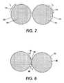
- FIG. 7is an illustration of inductive currents in conductor loops
- FIG. 8is an illustration of canceling inductive currents in conductor loops according to the concepts of the present invention.
- FIG. 9is a schematic of an embodiment of a pacemaker lead utilizing inductive loops according to the concepts of the present invention.
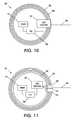
- FIG. 10is a schematic of an embodiment of inductive loops in a pacemaker canister according to the concepts of the present invention.
- FIG. 11is a schematic of an embodiment of inductive loops around a pacemaker canister according to the concepts of the present invention.
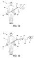
- FIG. 12illustrates of an embodiment of a medical device with an external voltage cancellation unit according to the concepts of the present invention
- FIG. 13illustrates of another embodiment of a medical device with an external voltage cancellation unit according to the concepts of the present invention
- FIG. 14illustrates a portion of coiled leads used in a medial device according to the concepts of the present invention
- FIG. 15illustrates another embodiment of a portion of coiled leads used in a medial device according to the concepts of the present invention
- FIG. 16illustrates a further embodiment of a portion of coiled leads used in a medial device according to the concepts of the present invention
- FIG. 17illustrates another embodiment of a portion of coiled leads used in a medial device according to the concepts of the present invention.
- FIG. 18illustrates a circuit diagram representing a guide wire with an unbalancing impedance circuit according to the concepts of the present invention
- FIG. 19illustrates another embodiment of a circuit diagram representing a guide wire with an unbalancing impedance circuit according to the concepts of the present invention
- FIG. 20illustrates a balun used in conjunction with a guide wire according to the concepts of the present invention.
- FIG. 21is a circuit diagram representing a capacitance unbalanced balun unit according to the concepts of the present invention.
- FIG. 1is a schematic showing a typical pacemaker arrangement 100 .
- the pacemakercomprises a pulse generator canister 102 housing a power supply (not shown) and electronic components (not shown) for sensing and producing electrical pacing pulses.
- the pulse generator canister 102has connected to it insulated conductive leads 104 that pass through the body (not shown) and into the heart 106 .
- Conventional bipolar pacemaker leadshave two conductive strands, one for pacing and sensing, and the other for ground.
- the path of the leads 104is generally not straight.
- the leads 104have one or more electrodes 112 in contact with the heart 106 .
- the direct line 108 from the heart 106 , where the electrodes 112 are placed, to the generator canister 102represents a conductive path comprising body tissue (not shown) and fluids (not shown).
- the completed loop from the pacemaker canister 102 , through the leads 104 , and back to the pacemaker canister 102 along the path 108is subject to Lenz's law. That is, a changing magnetic field 110 through the area enclosed by the completed loop (from the pacemaker canister 102 , through the leads 104 , and back to the pacemaker canister 102 along the path 108 ) can induce unwanted voltages in the leads 104 and across the heart 106 .
- the pacemaker canister 102is made out of a non-conductive material.
- the canister 102is coated or covered with various non-conductive insulating materials. This increases the overall resistance of the conductive path loop and thus reduces the voltage across the tissue between electrodes 112 and the canister 102 .
- Using a three-strand lead designallows for the separation of the pacing signals from the sensing signals and allows for different filtering techniques to be utilized on each separate conductive strand: one strand for the pacing signal for stimulating the heart, one conductive strand for the sensing of the heart's electrical state, pre-pulse, ecg, etc., and one strand for the ground path.
- Current bi-polar designsuse only two conductive strands. This means that the pacing and the sensing signals are carried on the same strand.
- the pacing signalgoes “down” (from generator canister to heart) the pacing lead (conductive strand) while the sensing signal travels “up” (from heart to generator canister) the pacing lead.
- Thisis the “standard” bipolar pacing setup. If a filter is added to the pacing/sensing strand to block the switch gradient induced signal caused by a MRI system, the pacing pulse/signal must travel through the filter, thereby distorting the pacing pulse.
- a diodefor example, can be put on the pacing strand and one or more filters can be put on the sensing strand.
- the filters on the sensing leadmay be at the distal end of the pacemaker lead or in the generator canister.
- the present inventionis able to utilize different kinds of filters (radio-frequency filters, high/low pass filters, notch filters, etc.) or other electronics in conjunction with each strand depending on the different signal characteristics and/or signal direction along the conductive strand.
- FIG. 2shows a schematic of a pacemaker arrangement 120 including a generator canister 122 containing a pacing pulse generator (not shown), sensing electronics (not shown) and other electronic components (not shown).
- Attached to the generator canister 122is a lead assembly 140 having three conductive strands 124 , 126 , and 128 through lumen 138 .
- Each of the conductive strands 124 , 126 , and 128pass through the distal tip 142 of the lead assembly 140 to exposed electrodes 132 , 134 , and 136 , respectively.
- the exposed electrodes 132 , 134 , and 136are placed in contact with or next to the heart.
- Conductive strand 124 and electrode 132are used to deliver pulses to the heart from a pacing generator within the canister 122 .
- Conductive strand 126 and electrode 134are used as a ground.
- Conductive strand 128 and electrode 136are utilized for sensing the electrical signals generated by the heart. In this way, the sensing functionality of pacemakers can be separated from the delivery of pacing pulses.
- a diode 130is inserted into the conductive strand 124 near the distal tip of the lead assembly 142 . It is noted that the diode 130 can also be is placed in the generator canister 122 .
- other electronic componentsi.e. radio-frequency chocks, notch filters, etc.
- Optional electronic components 146 and 144are used to block or significantly reduce any unwanted induced signals caused by the MRI system from passing along conductive strands 126 and 128 respectively while allowing the desired sensing signals from the heart to pass along conductive strand 126 to electronics in the generator canister 122 .
- FIG. 3is a schematic of an embodiment of the present invention.
- a patient 162is located within an MRI system 168 , wherein the patient 162 has an implanted heart pacemaker pulse generator canister 164 .
- a surface sensor/transceiver 166is placed on the exterior of the patient's body 162 over or near the location of the implanted pacemaker generator 164 .
- the sensor/transceiver 166is in communication with the MRI system 168 via communication line 170 , which may be an MRI safe cable such as a fiber optical cable.
- the sensor/transceiver 166is in communication with the implanted pacemaker pulse generator canister 164 .
- the means of communication between the sensor/transceiver 166 and the implanted pacemaker generator 164may be acoustic, optical, or other means that do not interfere with the imaging capabilities or image quality of the MRI system.
- the signalsmay be digital or analog.
- a transmitter/receiveris placed in the pacemaker canister 164 so that the MRI system 168 can be in operative communication with the pacemaker system and vice versa.
- the pacing systemcan transmit signals to the MRI system 168 indicating when the pacemaker is about to deliver a pacing pulse to the heart.
- the transmitted signalsmay be digital or analog.
- the MRI system 168stops or pauses the MRI switched gradient field (imaging scanning sequence) to allow the pacing pulse to occur. After the pacing pulse has been delivered to the heart, the MRI system 168 resumes or begins a new imaging scanning sequence.
- the MRI system 168sends signals to the implanted heart pacemaker pulse generator canister 164 through the sensor/transceiver 166 indicating the application of switched gradient fields.
- the pacemakermay use this information to switch filters or other electronics in and out of the circuit to reduce or eliminate voltages induced in the pacemaker leads by the gradient fields.
- the pacemakermay switch in additional resistance or inductance or impedance into the pacing/sensing and/or ground strands based on the signal from the MRI system 168 signifying the application of the gradient fields.
- the implanted heart pacemaker pulse generator canister 164can sense the application of the gradient fields. In response thereof, the pacemaker switches into the electrical circuit of the pacing/sense and/or ground leads a charging source which is used to charge the implanted heart pacemaker pulse generator canister 164 , leads, and/or electrodes to an electrical potential opposite to that which would be induced by the gradient fields. In this way, the induced voltages caused by the gradient fields are cancelled out or reduced to a safe level, by the application of this voltage source.
- the charging/voltage sourcereceives its power from inductively coupling to the MRI system's radio-frequency field.
- the oscillating radio-frequency fieldsupplies power to charge special capacitors in the implanted heart pacemaker pulse generator canister 164 .
- other external power sourcescan be used to power the charging/voltage source in the implanted heart pacemaker pulse generator canister 164 .
- FIG. 4is a diagram of an assembly 170 for the pacemaker generator components comprising the canister housing 172 , a programmable logic unit (PLU) 184 , a power source 174 , and a pulse generator 176 . Additionally, means for communicating with an external sensor/transceiver is provided by transceiver 180 . Other electronic components 178 ; e.g., signal filters, signal processors, lead connectors, etc. are also located in the canister 172 . The pacing leads 182 pass through the canister 172 and connect to the internal electronics 178 . During an NRI examination, the signals transmitted and received by the transceiver 180 may be used to synchronize the MRI system's scanning sequences with the delivery of the pacing signals.
- PLUprogrammable logic unit
- the pacing generator assembly 190further includes a second power module 186 which may be an inductive coil and/or capacitor bank, suitable for capturing and storing power from the MRI system's transmitted radio-frequency signal.
- a second power module 186which may be an inductive coil and/or capacitor bank, suitable for capturing and storing power from the MRI system's transmitted radio-frequency signal.
- the power stored in the power module 186is used to develop an electrical potential in the leads 182 that is opposed to that which is induced by the application of the MRI system's gradient fields.
- the power stored in the power module 186is used to operate various switches in the electronics module 178 which may switch in or out various power serge protection circuits in-line and/or signal filters to the leads 182 .
- the module 186may be used to electrically charge the pacemaker canister 172 , which is made of a conductive material, in synchronization with the application of the MRI system's gradient fields so that the electrical potential difference between the pacing electrodes and the pacemaker canister 172 is reduced. That is, the sum of the induced voltage difference due to the application of the gradient fields plus the voltage difference due to the application of the electrical charge stored in the power module 186 results is a net voltage significantly below any threshold level, above which a problem may develop.
- FIG. 6depicts another assembly 200 , which includes the basic components of FIG. 5 less the transceiver 180 , a gradient field detector 204 , and a by-pass switch component 202 .
- the pacemakercan switch filters and/or other electronics 178 in or out of the circuit.
- the switch 202when no gradient fields are detected, the switch 202 is closed to by-pass the electronics component 178 , which may be a combination of low-pass, high-pass, notch filters, diodes, and/or other electronics. In this mode (switched closed), the pacing pulse (and sensing signals) by-pass the filters components 178 .
- the switch 202When gradient field detector 204 detects the gradient signals, the switch 202 is opened and any gradient fields induced signals in the leads 182 are blocked or significantly reduced by the filters components 178 . In the open mode, the pacing and sensing signals pass through the filters component 178 as well.
- the gradient detector 204may communicate the sensing of the gradient field to other components in the pacemaker via its connection to the PLU 184 so that the pacing signal can be modified, if necessary, to compensate for any distortion it may suffer by now going through the filters component 178 . Additionally, the sensing signal, now also passing through the filter components 178 may be distorted. This may be compensated for by including signal recovery/reconstruction logic into the PLU or into a separate signal-processing component.
- the voltage across the tissue gap from the electrodes 112 and the pacemaker canister 102can be reduced. Inserting a resistor or using a higher resistive wire for the pacemaker leads 104 will reduce the current induced in the current loop, which includes the virtual loop portion across the (heart 112 ) tissue to the pacemaker generator canister 102 .
- the leads 104By using various inductors in-line with the various leads 104 , it is possible to make the leads 104 have a high impedance for the low frequency MRI gradient fields frequency and a low impedance for the MRI system's radio-frequency frequency. Alternatively, different impedances (inductors/resistors/capacitors) may be switched in-line or out of the leads'circuitry depending on the timing and application of the gradient and/or radio-frequency fields.
- the pacemakers'electronicscan be augmented to include one or more digital signal processors.
- the digital signal processorDSP
- the DSPcan reconstruct the sensing signal after it has passed through filters and has been distorted by the filtering or other elements that may have been added to the lead circuit.
- the DSPmay also be used to reject any signals that do not have a correct cardiac signature, thus rejecting any signals caused by the switched gradient fields, which is a non-cardiac signal.
- a pacemaker lead or other medical devicehaving a long conductive lead and functioning in an MRI environment, may be configured, according to the concepts of the present invention, to include additional loops to cancel the induced voltage effects in the leads of the original current loop formed by the leads.
- two conductive loops 260 and 270having the same amount of area and in the same plane, positioned in a changing magnetic field 262 and 272 , develop currents 264 and 274 .
- both induced currents I 1 and I 2travel in the same direction (clockwise direction shown) at all times as the magnetic field 262 and 272 oscillate.
- FIG. 8shows that by connecting the two conductive loops 260 and 270 of FIG. 7 to form a single conductor 280 , the currents induced in each lobe can be made to cancel each other out.
- the two loopsare connected so that a single conductor is formed which crosses over itself at 284 .
- the two currents 286 and 288cancel each other out resulting in net current of zero magnitude around the conductor 280 .
- This type of configuration of conductors in a changing magnetic fieldmay be used to cancel induced currents in the conductors.
- FIG. 9depicts an implanted pacemaker system 220 comprising a pacing generator canister 102 , conductive leads 104 , and electrodes 112 positioned in the heart 106 . Additional loops 222 are added to the overall configuration of the lead 104 in the body with one or more crossings 224 . In accordance with the concepts of the present invention, the plane of the loop 222 is in the same plane as defined by the rest of the lead geometry.
- the same oscillating magnetic field 110passes through loop 222 and the loop defined by generator canister 102 , conductive leads 104 , electrodes 112 , and conductive path 108 through the body from the heart 106 to the generator canister 102 . It is noted that the total area enclosed by the loops can be adjusted by adding or removing loops 222 or by changing the area enclosed by the loops (singly or collectively).
- the total area of the loop 222is the same as the loop area 226 . In another embodiment, the total area of the loop 222 is different from loop area 226 . In another embodiment, the plane of loop 222 is different from the plane of loop area 226 . In yet another embodiment, loop 222 and/or loop area 226 do not define a single plane but are curved in three different spatial directions. In yet another embodiment, loop 222 consists of at least three loops in three orthogonal planes.
- the new additional loops 222can be positioned in such a way as to encircle the pacemaker's generator canister 102 .
- the additional loops 222may be positioned inside the pacemaker's generator canister 102 .
- a fastener(not shown) can be used at the loop cross over point 224 to allow for adjustment of the loop's enclosed area and/or orientation and, once adjusted, to lock in the loop's adjustments.
- This same fastenercan also be used to adjust a plurality of loops.
- pacemaker's generator canister 102may include an orientation subsystem for automatically changing a spatial orientation of the coil to modify the strength of the MRI switched gradient field induced current.
- the orientation subsystemmay sense the magnitude of the MRI switched gradient field induced current (voltage) and spatially tune the orientation of the coils so as to produce more current to oppose the MRI switched gradient field induced current or less current to oppose the MRI switched gradient field induced current based upon the sensed magnitude of the MRI switched gradient field induced current (voltage).
- the orientation subsystemwould spatially move or adjust one or more coils such that their surface planes become more perpendicular to the MRI gradient field lines, thereby inducing a greater magnitude of current to oppose the MRI switched gradient field induced current.
- the orientation subsystemwould spatially move or adjust one or more coils such that their surface planes become less perpendicular and more parallel to the MRI gradient field lines, thereby inducing a lesser magnitude of current to oppose the MRI switched gradient field induced current.
- a selection mechanismcan be included in the pacemaker system. This selection mechanism is used to adjust the number of loops to include in the circuit.
- the selection mechanismcan be used to manually select how many loops to include in the lead circuit depending on where the pacemaker can is placed in the body and the length of the lead.
- the selection mechanismmay be used to automatically select how many loops to include in the lead circuit depending on where the pacemaker can is placed in the body and the length of the lead.
- the present inventionmonitors the voltages on the pacemaker's lead(s) and selects a different number of loops to connect to the lead(s) to cancel any induced voltages.
- the selection mechanismmay be externally programmed and transmitted to the pacemaker's PLU that then monitors and adjusts the number of loops in the lead circuit.
- FIG. 10is a schematic of a pacemaker system 300 that includes a pacemaker canister 302 and the pacemaker's leads 304 .
- the pacemaker's canister 302contains a programmable logic unit (PLU) 306 , and other electronics 310 , e.g. a pulse generator, power supply, etc.
- PLUprogrammable logic unit
- the system 300further includes conductive loops 308 positioned within the pacemaker canister 302 .
- the conductive loopsare connected to a loop selection component 312 that provides means for selectively adjusting the number of loops to be included in the leads'circuit 304 .
- the leads 304are also connected to the loop selection component 312 so that the leads 304 can be electrically connected to the loops 308 .
- the loop selection component 312connects the loops 308 to the leads'circuit 304 in such a way that any induced voltages in the loops 308 caused by changing magnetic fields in the environment, e.g. an MRI environment, will cancel out or significantly reduce in magnitude any induced voltage along the leads 304 that have also been caused by the environment's changing magnetic fields.
- the loop selection component 312is adjusted manually by screws, connection pins, and/or other means.
- the loop selection component 312is controlled by the PLU 306 .
- the PLU 306may include means for receiving loop selection instructions from an external transmitter or may include sensors that measure environmental variables, e.g. changing magnetic fields in an MRI environment. From this information, the PLU 306 dynamically adjusts the loop selection component's 312 adjustable parameters so as to change which loops are included in the leads'circuitry 304 . It is noted that the loops 308 need not be all in the same plane.
- pacemaker's generator canister 302may include an orientation subsystem for automatically changing a spatial orientation of the coil to modify the strength of the MRI switched gradient field induced current.
- the orientation subsystemmay sense the magnitude of the MRI switched gradient field induced current (voltage) and spatially tune the orientation of the coils so as to produce more current to oppose the MRI switched gradient field induced current or less current to oppose the MRI switched gradient field induced current based upon the sensed magnitude of the MRI switched gradient field induced current (voltage).
- the orientation subsystemwould spatially move or adjust one or more coils such that their surface planes become more perpendicular to the MRI gradient field lines, thereby inducing a greater magnitude of current to oppose the MRI switched gradient field induced current.
- the orientation subsystemwould spatially move or adjust one or more coils such that their surface planes become less perpendicular and more parallel to the MRI gradient field lines, thereby inducing a lesser magnitude of current to oppose the MRI switched gradient field induced current.
- FIG. 11is a schematic of another pacemaker system 320 .
- Pacemaker system 320includes conductive loops 322 positioned externally to a pacemaker canister 302 .
- the loops 332are connected to an input port connection 330 and to an output port connection 334 which are electrically connected to the loop selection component 324 located inside the pacemaker canister 302 .
- the pacemaker leads 304are connected to an electrical connector 332 that is electrically connected to the loop selection component 324 . It is noted that the conductive loops 322 need not be all in the same plane.
- pacemaker system 320may include an orientation subsystem for automatically changing a spatial orientation of the coil to modify the strength of the MRI switched gradient field induced current.
- the orientation subsystemmay sense the magnitude of the MRI switched gradient field induced current (voltage) and spatially tune the orientation of the coils so as to produce more current to oppose the MRI switched gradient field induced current or less current to oppose the MRI switched gradient field induced current based upon the sensed magnitude of the MRI switched gradient field induced current (voltage).
- the orientation subsystemwould spatially move or adjust one or more coils such that their surface planes become more perpendicular to the MRI gradient field lines, thereby inducing a greater magnitude of current to oppose the MRI switched gradient field induced current.
- the orientation subsystemwould spatially move or adjust one or more coils such that their surface planes become less perpendicular and more parallel to the MRI gradient field lines, thereby inducing a lesser magnitude of current to oppose the MRI switched gradient field induced current.
- FIG. 12depicts a medical procedure in which a catheter 406 or other medical device, e.g. a guidewire, which is comprised of conductive leads or other conductive components, may be partially inserted into a body 402 and partially external to the body.
- a catheter 406 or other medical devicee.g. a guidewire, which is comprised of conductive leads or other conductive components
- conductive medical devices 406can develop problems like heating, induced voltages, etc. caused by the changing magnetic fields of the MRI system.
- a voltage compensation unit (VCU) 410is electrically connected to the medical device 406 via conductive leads 412 and electrical connectors 414 , externally to the patient's body 402 .
- VCUvoltage compensation unit
- the medical device 406is constructed with additional electrical connectors 414 to allow for easy attachment of the VCU device 410 .
- the VCU device 410is connected to a power supply or may have a built in power supply, e.g. batteries.
- the VCU device 410has sensors built into it, which monitor the voltages of the conductive components in the medical device 406 , and delivers opposing voltages to the medical device 406 to cancel out or significantly reduce any induced voltages caused by the changing magnetic fields in an MRI (or other) environment.
- the VCU device 410has sensors to detect the changing magnetic fields of the MRI system and can synchronize the application of the canceling voltage with the MRI System's changing fields.
- the VCU device 420is connected to the MRI system 422 via communication means 424 so that the start and end of the application of the MRI system's 422 fields may be communicated to the VCU device 420 .
- Other information that may be requiredmay also be communicated to the VCU device 420 .
- the communication means 424may be electrical wires/coaxial/shielded/other, optical fiber, or a radio-frequency transmitter/receiver, or some sonic means of communication.
- the conductive lead of a heart pacemakeris a filer winding.
- the filer windingmay consist of two or more conductive stands coiled together in a spring-like configuration.
- the currentpulse, signals
- the currentthen flows over the surface and through the contact points between one loop and the adjacent loop of the winding, rather than following the windings of the individual conductive strands. This occurs because there is no significant insulating material or surface coating between the contact points of the windings.
- the inductance value of the pacemaker's leadmay be changed to increase the overall impedance of the pacemaker's lead.
- a suitable radio-frequency chokeis inserted inline with the pacemaker's lead, preferable near the distal tip.
- electronic component 146 and/or 144may comprise a radio-frequency choke.
- the radio-frequency chokehas an inductance value of about 10 microHenries. In another embodiment, the inductance value is about 2 microHenries.
- inductance to introduce into the, for example, pacemaker's leaddepends in part on the frequency of the induced signal from the MRI system's imaging sequence that is to be blocked or significantly reduced.
- FIG. 14shows a portion of a coiled multi-filer lead 450 .
- lead 450includes a plurality of coil loops 452 ; each coil loop 452 consists of three conductive strands 454 , 456 , and 458 .
- a current 460 through the lead 450can cross contact points 464 , 466 , and 462 between the strands as well as the coil contact points 468 and 470 .
- the current 460does not follow the coiling of the lead's conductive strands 454 , 456 , and 458 .
- FIG. 15shows a portion of a coiled lead assembly 480 including a region 482 that has an insulating coating 484 applied to its surface.
- the coiled lead assembly 480is depicted in an elongated position in which adjacent coil windings are not in contact with one another. It is to be understood that the normal, relaxed position of the lead assembly 480 has all adjacent coiled windings in contact.
- the current 490 , 492 , and 494is now forced to substantially follow the curvature of the coiled winding 482 , thus forming an inductive coil inline with the conductive lead regions 486 and 488 which do not have an insulated coating.
- the inductive value of the created inductorcan be adjusted by adjusting the length of the region to which the insulative coating 484 is applied.
- the coating 484may be a partially resistive material.
- the inductanceis then adjusted by adjusting the resistive properties of the material 484 .
- FIG. 16is a schematic of a coiled lead assembly 500 comprised of uninsulated regions 502 , 504 , and 506 , and coated insulated regions 508 and 510 with coatings 512 , and 514 , respectively.
- the currentis forced to substantially follow the curvature of the coiled windings, thus forming an inductive coil inline with the conductive lead regions that do not have a coating applied thereto.
- the inductive value of the created inductorcan be adjusted by adjusting the length of the region to which the insulative coatings 512 and 514 are applied.
- coatings 512 and 514are the same coatings. In another embodiment, the coatings 512 and 514 are different materials.
- coatings 512 and 514may be the same coating material but having differing properties, e.g., the thickness of the coatings, or the length of the coated region 508 and 510 . It is further noted that the two-coated regions 508 and 510 may have different inductive values. It is also noted that more than two different regions along the length of the lead assembly can be coated.
- FIG. 17is a schematic of a portion of a coiled lead assembly 520 including at least one region 524 with a coating applied thereto.
- the currentis forced to substantially follow the curvature of the coiled windings, thus forming an inductive coil inline with the conductive lead regions 522 and 526 that do not have a coating applied thereto.
- the inductive value of the created inductorcan be adjusted by adjusting the length of the region to which the insulative coating 524 is applied.
- a rod 528which also changes the inductive value of the coated region 524 .
- the rod 528may be of ferrite material. It is further noted that multiple rods can be inserted into multiple coated regions along the length of the coiled lead.
- multiple coatingscan be applied to the same coated region of the coiled lead wherein the multiple coating layers may be comprised of different materials. It is further noted that one or more layers of the multiple layers of coatings may comprise ferrite material.
- the heating and/or induced voltages on catheters or guide wiresis controlled or substantially eliminated by introducing or creating detuned characteristic impedance at a proximal ends (ends that are not within the body) of the catheters or guide wires. This introduction or creation of detuned characteristic impedance will be discussed in more detail with respect to FIGS. 18-21 .
- catheters and guide wiresare used to measure physiological signals.
- two-wire catheters or guide wires having a grounded shieldhave one conductor that carries the actual measured signal and the other wire is grounded.
- characteristic impedancethe two-wire catheters or guide wires having a grounded shield are unbalanced.
- a single wire catheter or guide wirehas characteristic impedance that is balanced.
- the characteristic impedance of the catheters and guide wires, used during MRI proceduresshould be unbalanced at the proximal end, under all conditions, to reduce or eliminate heating and induced voltages.
- the present inventionproposes providing a Balun along the catheter and/or guide wire or at the proximal end of the catheter and/or guide wire.
- the reactance at the distal end of the catheter and/or guide wireapproaches infinity.
- the unbalanced characteristic impedancehas approximately four times the ground loop looses of a balanced line, thereby substantially avoiding any incident of thermal injury.
- An example of such an arrangementis illustrated in FIG. 18 .
- a guide wire or catheter 650has characteristic impedance due to its intrinsic resistance from intrinsic resistor capacitors R P and its intrinsic inductance from intrinsic inductor L.
- a Balun 600is placed along the guide wire or catheter 650 . In other words, the Balun 600 is in vitro.
- the Balun 600includes a variable capacitor C 1 connected in parallel with the guide wire or catheter 650 and two variable capacitors C 2 and C 3 connected in series with the guide wire or catheter 650 . It is noted that one end of the variable capacitor C 2 is connected to the shield 625 and ground or a known voltage. The capacitance of the variable capacitors C 1 , C 2 , and C 3 are adjusted to create the unbalanced characteristic impedance.
- variable capacitors C 1 , C 2 , and C 3may be used for both matching and providing a certain amount of balancing for the guide wire or catheter 650 characteristic impedance.
- the variable capacitors C 1 , C 2 , and C 3lift the voltage on the guide wire or catheter 650 from ground. The larger the reactance of the variable capacitors C 1 , C 2 , and C 3 , the more symmetric and balanced the circuit of the guide wire or catheter 650 becomes.
- the circuit of the guide wire or catheter 650becomes asymmetric and unbalanced, breaking down, to reduce the chances of thermal injury at the distal end of the guide wire or catheter 650 due to heating from induced voltages.
- FIG. 19illustrates another embodiment of the present invention wherein a guide wire or catheter 6500 has characteristic impedance due to its intrinsic capacitance from intrinsic capacitors C t , and C s and its intrinsic inductance from intrinsic inductor L.
- a Balun 6000is connected across the proximal end of the guide wire or catheter 6500 .
- the Balun 6000is outside the body at the proximal end of the guide wire or catheter 650 .
- the Balun 6000includes a variable capacitor C 1 connected in parallel with the guide wire or catheter 6500 and a variable capacitor C 2 connected in series with the guide wire or catheter 6500 . It is noted that one end of the variable capacitor C 1 is connected to the shield 6250 and ground or a known voltage. The capacitance of the variable capacitors C 1 and C 2 are adjusted to create the unbalanced characteristic impedance.
- variable capacitors C 1 , and C 2may be used for both matching and providing a certain amount of balancing for the guide wire or catheter 6500 characteristic impedance.
- the variable capacitors C 1 , C 2 , and C 3lift the voltage on the guide wire or catheter 6500 from ground. The larger the reactance of the variable capacitors C 1 and C 2 , the more symmetric and balanced the circuit of the guide wire or catheter 6500 becomes.
- the circuit of the guide wire or catheter 6500becomes asymmetric and unbalanced, breaking down, to reduce the chances of thermal injury at the distal end of the guide wire or catheter 6500 due to heating from induced voltages.
- FIG. 20illustrates a further embodiment of the present invention wherein a guide wire or catheter 800 is connected to a Balun 700 .
- the Balun 700includes a variable capacitor 710 , a copper foil 720 , and a non-conductive tuning bolt 730 .
- the Balun 700is further connected to the output of the probe 800
- the Balun 700adjusts its characteristic impedance by increasing or decreasing the number wire coils are found within the copper foil 720 .
- the combination of the coils and the copper foil 720forms a variable capacitor, having it impedance determined by the change in the surface area of the coils positioned opposite of the copper foil 720 .
- the capacitance of this combinationincreases.
- the capacitance of this combinationdecreases.
- the capacitance of the Balun 700is adjusted to create the unbalanced characteristic impedance.
- FIG. 21illustrates another embodiment of the present invention wherein a guide wire or catheter 900 is electronically isolated by a voltage control unit to always appear as an unbalanced line to any possible magnetic field that may be applied from a magnetic resonance imager unit (not shown).
- a tapped voltage from a voltage-controlled oscillator in the magnetic resonance imaging unitis applied across terminals X 1 and X 2 of the voltage control unit.
- a capacitance unbalanced balun unit 7000located within the voltage control unit, is connected through a variable inductor 910 to the proximal end of the guide wire or catheter 900 .
- the voltage control unit containing the capacitance unbalanced balun unit 7000is outside the body at the proximal end of the guide wire or catheter 900 .
- the varying of the reactance (X 0 ) of the guide wire or catheter 900can be readily adjusted and automatically controlled by the voltage control unit circuit's reactance to the tapped voltage from the voltage-controlled oscillator in the magnetic resonance imaging unit as it is applied across X 1 and X 2 for any instance of time from time zero (T 0 ) or instantiation of the magnetic resonance imaging radio-frequency pulses.
- the capacitance unbalanced balun unit 7000includes two non-magnetic trimmer capacitors C 1 and C 2 connected in parallel with LC circuits (L 1 ,C 3 ) and (L 2 ,C 4 ), respectively, setting up a simplified dual T network that is effectively in series with the guide wire or catheter 900 . It is noted that one end of the simplified dual T network is connected to neutral H 1 and the other end is connected to a continuously variable voltage H 2 , based on inputs to the circuit from the voltage-controlled oscillator in the magnetic resonance imaging unit at X 1 and X 2 . The reactance (X 0 ) of the LC circuits in the T network is automatically adjusted to create the desired unbalanced characteristic impedance.
- the T network L 1 , C 1 , C 3 and L 2 , C 2 , C 4 respectively,may be used for both matching and unmatching characteristic impedance of the guide wire or catheter 900 and to provide a certain amount of balancing or unbalancing for the guide wire or catheter 900 by varying the circuit's capacitive or inductive reactance (X 0 ).
- the voltage control unit (X 1 X 2 )As the voltage from the voltage-controlled oscillator in the magnetic resonance imaging unit is provided to the voltage control unit (X 1 X 2 ), the two non-magnetic trimmer capacitors C 1 and C 2 , connected in parallel with LC circuits, (L 1 ,C 3 ) and (L 2 ,C 4 ), lift the voltage on the guide wire or catheter 900 from ground to an unbalanced state with respect to the radio-frequency pulse applied by the magnetic resonance imaging unit.
- the present inventionis directed to a system for reducing the effects of MRI induced signals to a safe level having a medical device that includes a housing having electronic circuitry therein, a first lead to provide an electrical path for a stimulation signal generated by the electronic circuitry to be applied to a desired tissue region, a second lead to provide an electrical path for a sensed physiological condition of the desired tissue region to be communicated to the electronic circuitry, and a third lead to provide an electrical ground.
- a diodeis connected to the first lead to significantly reduce MRI induced signals from traveling along the first lead to the electronic circuitry.
- This embodiment of the present inventionmay also include a filter, connected to the second lead, to significantly reduce MRI induced signals from traveling along the second lead to the electronic circuitry; a second filter, connected to the third lead, to significantly reduce MRI induced signals from traveling along the third lead to the electronic circuitry; a sensor to sense application of switched MRI gradient fields; an electronic component, connected to the second lead, to significantly reduce MRI induced signals from traveling along the second lead to the electronic circuitry; and/or a switch, connected to the sensor and the electronic component, to operatively connect the electronic component to the second lead when the sensor senses the application of switched MRI gradient fields and to operatively disconnect the electronic component from the second lead when the sensor fails to sense the application of switched MRI gradient fields.
- the electronic componentmay be a filter, impedance, an inductor, a resistor, and/or a capacitor.
- the electronic componentmay be a source that generates an electrical potential opposite to that which would be induced by the MRI switched gradient fields so as to reduce voltages induced by the MRI switched gradient fields to a safe level or a coil that generates a MRI switched gradient field induced current opposite to that which would be induced by the MRI switched gradient fields in the leads so as to reduce voltages induced by the MRI switched gradient fields to a safe level wherein the coil may be curved in three different spatial directions.
- the electronic component having the coilmay also include an orientation subsystem for changing a spatial orientation of the coil to modify the strength of the MRI switched gradient field induced current.
- the electronic componentmay include a plurality of coils, each coil generating a MRI switched gradient field induced current opposite to that which would be induced by the MRI switched gradient fields in the leads so as to reduce voltages induced by the MRI switched gradient fields to a safe level, and a switch connecting independently a number of the plurality of the coils, the number of connected coils corresponding to an amount of the voltage induced by the MRI switched gradient fields and a current level produced in each coil when the sensor senses the application of switched MRI gradient fields wherein the coils are curved in three different spatial directions.
- the electronic componentmay also include an orientation subsystem for changing a spatial orientation of the coils to modify the strength of the MRI switched gradient field induced currents.
- the electronic componentmay be three orthogonally planar coils, each coil generating a MRI switched gradient field induced current opposite to that which would be induced by the MRI switched gradient fields in the leads so as to reduce voltages induced by the MRI switched gradient fields to a safe level, and a switch connecting independently a number of the coils, the number of connected coils corresponding to an amount of the voltage induced by the MRI switched gradient fields and a current level produced in each coil when the sensor senses the application of switched MRI gradient fields.
- the electronic componentmay also include an orientation subsystem for changing a spatial orientation of the coils to modify the strength of the MRI switched gradient field induced currents wherein each coil defines a distinct plane that transverses the MRI switched gradient fields.
- This embodimentmay also include a receiver to receive a signal from a MRI system indicating an application of switched MRI gradient fields; an electronic component, operatively connected to the second lead, to significantly reduce MRI induced signals from traveling along the second lead to the electronic circuitry; and a switch, operatively connected to the receiver and the electronic component, to operatively connect the electronic component to the second lead when the receiver receives an indication of the application of switched MRI gradient fields and to operatively disconnect the electronic component from the second lead when the receiver receives a signal indicating no application of switched MRI gradient fields.
- the electronic componentmay be a filter, impedance, an inductor, a resistor, and/or a capacitor.
- the electronic componentmay be a source that generates an electrical potential opposite to that which would be induced by the MRI switched gradient fields so as to reduce voltages induced by the MRI switched gradient fields to a safe level or a coil that generates a MRI switched gradient field induced current opposite to that which would be induced by the MRI switched gradient fields in the leads so as to reduce voltages induced by the MRI switched gradient fields to a safe level wherein the coil may be curved in three different spatial directions.
- the electronic component having the coilmay also include an orientation subsystem for changing a spatial orientation of the coil to modify the strength of the MRI switched gradient field induced current.
- the electronic componentmay include a plurality of coils, each coil generating a MRI switched gradient field induced current opposite to that which would be induced by the MRI switched gradient fields in the leads so as to reduce voltages induced by the MRI switched gradient fields to a safe level, and a switch connecting independently a number of the plurality of the coils, the number of connected coils corresponding to an amount of the voltage induced by the MRI switched gradient fields and a current level produced in each coil when the sensor senses the application of switched MRI gradient fields wherein the coils are curved in three different spatial directions.
- the electronic componentmay also include an orientation subsystem for changing a spatial orientation of the coils to modify the strength of the MRI switched gradient field induced currents.
- the electronic componentmay be three orthogonally planar coils, each coil generating a MRI switched gradient field induced current opposite to that which would be induced by the MRI switched gradient fields in the leads so as to reduce voltages induced by the MRI switched gradient fields to a safe level, and a switch connecting independently a number of the coils, the number of connected coils corresponding to an amount of the voltage induced by the MRI switched gradient fields and a current level produced in each coil when the sensor senses the application of switched MRI gradient fields.
- the electronic componentmay also include an orientation subsystem for changing a spatial orientation of the coils to modify the strength of the MRI switched gradient field induced currents wherein each coil defines a distinct plane that transverses the MRI switched gradient fields.
- the present inventionis directed to a system for reducing the effects of MRI induced signals to a safe level.
- the systemincludes a MRI system; a medical device; and a transceiver to provide communication between the MRI system and the medical device.
- the medical devicehas a housing having electronic circuitry therein, a bi-directional lead to provide an electrical path for a stimulation signal generated by the electronic circuitry to be applied to a desired tissue region and to provide an electrical path for a sensed physiological condition of the desired tissue region to be communicated to the electronic circuitry, and a lead to provide an electrical ground.
- the medical deviceindicates to the MRI system, through the transceiver, when the stimulation signal will be applied to the desired tissue region.
- the MRI systemin response to the indication from the medical device of when the stimulation signal will be applied to the desired tissue region, terminates a production of MRI switched gradient fields.
- This embodimentmay further include a filter, connected to the bi-directional lead, to significantly reduce MRI induced signals from traveling along the bi-directional lead to the electronic circuitry; a filter, connected to the lead, to significantly reduce MRI induced signals from traveling along the lead to the electronic circuitry; a sensor to sense application of switched MRI gradient fields; an electronic component, connected to the bi-directional lead, to significantly reduce MRI induced signals from traveling along the bi-directional lead to the electronic circuitry; and/or a switch, connected to the sensor and the electronic component, to operatively connect the electronic component to the bi-directional lead when the sensor senses the application of switched MRI gradient fields and to operatively disconnect the electronic component from the bi-directional lead when the sensor fails to sense the application of switched MRI gradient fields.
- the electronic componentmay be a filter, impedance, an inductor, a resistor, and/or a capacitor.
- the electronic componentmay be a source that generates an electrical potential opposite to that which would be induced by the MRI switched gradient fields so as to reduce voltages induced by the MRI switched gradient fields to a safe level or a coil that generates a MRI switched gradient field induced current opposite to that which would be induced by the MRI switched gradient fields in the leads so as to reduce voltages induced by the MRI switched gradient fields to a safe level wherein the coil may be curved in three different spatial directions.
- the electronic component having the coilmay also include an orientation subsystem for changing a spatial orientation of the coil to modify the strength of the MRI switched gradient field induced current.
- the electronic componentmay include a plurality of coils, each coil generating a MRI switched gradient field induced current opposite to that which would be induced by the MRI switched gradient fields in the leads so as to reduce voltages induced by the MRI switched gradient fields to a safe level, and a switch connecting independently a number of the plurality of the coils, the number of connected coils corresponding to an amount of the voltage induced by the MRI switched gradient fields and a current level produced in each coil when the sensor senses the application of switched MRI gradient fields wherein the coils are curved in three different spatial directions.
- the electronic componentmay also include an orientation subsystem for changing a spatial orientation of the coils to modify the strength of the MRI switched gradient field induced currents.
- the electronic componentmay be three orthogonally planar coils, each coil generating a MRI switched gradient field induced current opposite to that which would be induced by the MRI switched gradient fields in the leads so as to reduce voltages induced by the MRI switched gradient fields to a safe level, and a switch connecting independently a number of the coils, the number of connected coils corresponding to an amount of the voltage induced by the MRI switched gradient fields and a current level produced in each coil when the sensor senses the application of switched MRI gradient fields.
- the electronic componentmay also include an orientation subsystem for changing a spatial orientation of the coils to modify the strength of the MRI switched gradient field induced currents wherein each coil defines a distinct plane that transverses the MRI switched gradient fields.
- the present inventionis directed to a system for reducing the effects of MRI induced signals to a safe level.
- the systemincludes a medical device wherein the medical device has a housing having electronic circuitry therein, leads to provide an electrical path for a stimulation signal generated by the electronic circuitry to be applied to a desired tissue region and to provide an electrical path for a sensed physiological condition of the desired tissue region to be communicated to the electronic circuitry, a sensor to sense application of switched MRI gradient fields, an electronic component, operatively connected to the leads, to significantly reduce MRI induced signals from traveling along the leads to the electronic circuitry, and a switch, operatively connected to the sensor and the electronic component, to operatively connect the electronic component to the leads when the sensor senses the application of switched MRI gradient fields and to operatively disconnect the electronic component from the leads when the sensor fails to sense the application of switched MRI gradient fields.
- the electronic componentmay be a source that generates an electrical potential opposite to that which would be induced by the MRI switched gradient fields so as to reduce voltages induced by the MRI switched gradient fields to a safe level or a coil that generates a MRI switched gradient field induced current opposite to that which would be induced by the MRI switched gradient fields in the leads so as to reduce voltages induced by the MRI switched gradient fields to a safe level wherein the coil may be curved in three different spatial directions.
- the electronic component having the coilmay also include an orientation subsystem for changing a spatial orientation of the coil to modify the strength of the MRI switched gradient field induced current.
- the electronic componentmay include a plurality of coils, each coil generating a MRI switched gradient field induced current opposite to that which would be induced by the MRI switched gradient fields in the leads so as to reduce voltages induced by the MRI switched gradient fields to a safe level, and a switch connecting independently a number of the plurality of the coils, the number of connected coils corresponding to an amount of the voltage induced by the MRI switched gradient fields and a current level produced in each coil when the sensor senses the application of switched MRI gradient fields wherein the coils are curved in three different spatial directions.
- the electronic componentmay also include an orientation subsystem for changing a spatial orientation of the coils to modify the strength of the MRI switched gradient field induced currents.
- the electronic componentmay be three orthogonally planar coils, each coil generating a MRI switched gradient field induced current opposite to that which would be induced by the MRI switched gradient fields in the leads so as to reduce voltages induced by the MRI switched gradient fields to a safe level, and a switch connecting independently a number of the coils, the number of connected coils corresponding to an amount of the voltage induced by the MRI switched gradient fields and a current level produced in each coil when the sensor senses the application of switched MRI gradient fields.
- the electronic componentmay also include an orientation subsystem for changing a spatial orientation of the coils to modify the strength of the MRI switched gradient field induced currents wherein each coil defines a distinct plane that transverses the MRI switched gradient fields.
- the present inventionis directed to an electrical lead component for a medical device that reduces the effects of MRI induced signals to a safe level.
- the electrical lead componentincludes a medical device electrical lead capable of providing an electrical path to a desired tissue region and a coil that generates a MRI switched gradient field induced current opposite to that which would be induced by the MRI switched gradient fields in the medical device electrical lead so as to reduce voltages induced by the MRI switched gradient fields to a safe level.
- the coilmay be curved in three different spatial directions.
- the embodimentmay further include an orientation subsystem for changing a spatial orientation of the coil to modify the strength of the MRI switched gradient field induced current.
- the present inventionis directed to an electrical lead component for a medical device that reduces the effects of MRI induced signals to a safe level.
- the electrical lead componentincludes a medical device electrical lead capable of providing an electrical path to a desired tissue region and a plurality of coils, each coil generating a MRI switched gradient field induced current such a combination of the MRI switched gradient field induced currents provide a combined current that is opposite to that which would be induced by the MRI switched gradient fields in the medical device electrical lead so as to reduce voltages induced by the MRI switched gradient fields to a safe level.
- the coilmay be curved in three different spatial directions.
- the embodimentmay further include an orientation subsystem for changing a spatial orientation of the coil to modify the strength of the MRI switched gradient field induced current.
- the present inventionis directed to an electrical lead component for a medical device that reduces the effects of MRI induced signals to a safe level.
- the electrical lead componentincludes a medical device electrical lead capable of providing an electrical path to a desired tissue region and three orthogonally planar coils, each coil generating a MRI switched gradient field induced current such a combination of the MRI switched gradient field induced currents provide a combined current that is opposite to that which would be induced by the MRI switched gradient fields in the medical device electrical lead so as to reduce voltages induced by the MRI switched gradient fields to a safe level.
- the present inventionis directed to an electrical lead component for a medical device that reduces the effects of MRI induced signals to a safe level.
- the electrical lead componentincludes a medical device electrical lead capable of providing an electrical path to a desired tissue region; a plurality of coils, each coil generating a MRI switched gradient field induced current; a sensor to measure a strength of voltages induced by the MRI switched gradient fields; and a switching device, operatively connected to the sensor and plurality of coils, to operatively connect a number of the plurality of coils in response to the measured strength of voltages induced by the MRI switched gradient fields such that a combination of the MRI switched gradient field induced currents produced by the number of operatively connected switches provide a combined current that is opposite to that which would be induced by the MRI switched gradient fields in the medical device electrical lead so as to reduce voltages induced by the MRI switched gradient fields to a safe level.
- the coilsmay be curved in three different spatial directions.
- the embodimentmay further include an orientation subsystem for changing a spatial orientation of the coil to modify the strength of the MRI switched gradient field induced current.
- the present inventionis directed to an electrical lead component for a medical device that reduces the effects of MRI induced signals to a safe level.
- the electrical lead componentincludes a medical device electrical lead capable of providing an electrical path to a desired tissue region; three orthogonally planar coils, each coil generating a MRI switched gradient field induced current; a sensor to measure a strength of voltages induced by the MRI switched gradient fields; and a switching device, operatively connected to the sensor and the coils, to operatively connect a number of the coils in response to the measured strength of voltages induced by the MRI switched gradient fields such that a combination of the MRI switched gradient field induced currents produced by the number of operatively connected switches provide a combined current that is opposite to that which would be induced by the MRI switched gradient fields in the medical device electrical lead so as to reduce voltages induced by the MRI switched gradient fields to a safe level.
- the present inventionis directed to an electrical lead component for a medical device that reduces the effects of MRI induced signals to a safe level.
- the electrical lead componentincludes a medical device electrical lead capable of providing an electrical path to a desired tissue region; a plurality of coils, each coil generating a MRI switched gradient field induced current; a transceiver to receive a signal indicating a number of coils to be connected; and a switching device, operatively connected to the transceiver and plurality of coils, to operatively connect a number of the plurality of coils in response to the received signal indicating the number of coils to be connected such that a combination of the MRI switched gradient field induced currents produced by the number of operatively connected switches provide a combined current that is opposite to that which would be induced by the MRI switched gradient fields in the medical device electrical lead so as to reduce voltages induced by the MRI switched gradient fields to a safe level.
- the coilsmay be curved in three different spatial directions.
- the embodimentmay further include an orientation subsystem for changing a spatial orientation of the coil to modify the strength of the MRI switched gradient field induced current.
- the present inventionis directed to an electrical lead component for a medical device that reduces the effects of MRI induced signals to a safe level.
- the electrical lead componentincludes a medical device electrical lead capable of providing an electrical path to a desired tissue region; three orthogonally planar coils, each coil generating a MRI switched gradient field induced current; a transceiver to receive a signal indicating a number of coils to be connected; and a switching device, operatively connected to the transceiver and the coils, to operatively connect a number of the coils in response to the received signal indicating the number of coils to be connected such that a combination of the MRI switched gradient field induced currents produced by the number of operatively connected switches provide a combined current that is opposite to that which would be induced by the MRI switched gradient fields in the medical device electrical lead so as to reduce voltages induced by the MRI switched gradient fields to a safe level.
- the present inventionis directed to a medical device that reduces the effects of MRI induced signals to a safe level.
- the medical deviceincludes a medical device capable of providing medical treatment to a desired tissue region and a coil that generates a MRI switched gradient field induced current opposite to that which would be induced by the MRI switched gradient fields in the medical device so as to reduce voltages induced by the MRI switched gradient fields to a safe level.
- the coilmay be curved in three different spatial directions.
- the embodimentmay further include an orientation subsystem for changing a spatial orientation of the coil to modify the strength of the MRI switched gradient field induced current.
- the present inventionis directed to a medical device that reduces the effects of MRI induced signals to a safe level.
- the medical deviceincludes a medical device capable of providing medical treatment to a desired tissue region and a plurality of coils, each coil generating a MRI switched gradient field induced current such a combination of the MRI switched gradient field induced currents provide a combined current that is opposite to that which would be induced by the MRI switched gradient fields in the medical device so as to reduce voltages induced by the MRI switched gradient fields to a safe level.
- the coilsmay be curved in three different spatial directions.
- the embodimentmay further include an orientation subsystem for changing a spatial orientation of the coil to modify the strength of the MRI switched gradient field induced current.
- the present inventionis directed to a medical device that reduces the effects of MRI induced signals to a safe level.
- the medical deviceincludes a medical device capable of providing medical treatment to a desired tissue region and three orthogonally planar coils, each coil generating a MRI switched gradient field induced current such a combination of the MRI switched gradient field induced currents provide a combined current that is opposite to that which would be induced by the MRI switched gradient fields in the medical device so as to reduce voltages induced by the MRI switched gradient fields to a safe level.
- the present inventionis directed to a medical device that reduces the effects of MRI induced signals to a safe level.
- the medical deviceincludes a medical device capable of providing medical treatment to a desired tissue region; a plurality of coils, each coil generating a MRI switched gradient field induced current; a sensor to measure a strength of voltages induced by the MRI switched gradient fields; and a switching device, operatively connected to the sensor and plurality of coils, to operatively connect a number of the plurality of coils in response to the measured strength of voltages induced by the MRI switched gradient fields such that a combination of the MRI switched gradient field induced currents produced by the number of operatively connected switches provide a combined current that is opposite to that which would be induced by the MRI switched gradient fields in the medical device so as to reduce voltages induced by the MRI switched gradient fields to a safe level.
- the coilsmay be curved in three different spatial directions.
- the embodimentmay further include an orientation subsystem for changing a spatial orientation of the coil to modify the strength of the MRI switched gradient field induced current.
- the present inventionis directed to a medical device that reduces the effects of MRI induced signals to a safe level.
- the medical deviceincludes a medical device capable of providing medical treatment to a desired tissue region; three orthogonally planar coil, each coil generating a MRI switched gradient field induced current; a sensor to measure a strength of voltages induced by the MRI switched gradient fields; and a switching device, operatively connected to the sensor and plurality of coils, to operatively connect a number of the plurality of coils in response to the measured strength of voltages induced by the MRI switched gradient fields such that a combination of the MRI switched gradient field induced currents produced by the number of operatively connected switches provide a combined current that is opposite to that which would be induced by the MRI switched gradient fields in the medical device so as to reduce voltages induced by the MRI switched gradient fields to a safe level.
- the present inventionis directed to a medical device that reduces the effects of MRI induced signals to a safe level.
- the medical deviceincludes a medical device capable of providing medical treatment to a desired tissue region; a plurality of coils, each coil generating a MRI switched gradient field induced current; a transceiver to receive a signal indicating a number of coils to be connected; and a switching device, operatively connected to the transceiver and the coils, to operatively connect a number of the coils in response to the received signal indicating the number of coils to be connected such that a combination of the MRI switched gradient field induced currents produced by the number of operatively connected switches provide a combined current that is opposite to that which would be induced by the MRI switched gradient fields in the medical device electrical lead so as to reduce voltages induced by the MRI switched gradient fields to a safe level.
- the coilsmay be curved in three different spatial directions.
- the embodimentmay further include an orientation subsystem for changing a spatial orientation of the coil to modify the strength of the MRI switched gradient field induced current.
- the present inventionis directed to a medical device that reduces the effects of MRI induced signals to a safe level.
- the medical deviceincludes a medical device capable of providing medical treatment to a desired tissue region; three orthogonally planar coil, each coil generating a MRI switched gradient field induced current; a transceiver to receive a signal indicating a number of coils to be connected; and a switching device, operatively connected to the transceiver and the coils, to operatively connect a number of the coils in response to the received signal indicating the number of coils to be connected such that a combination of the MRI switched gradient field induced currents produced by the number of operatively connected switches provide a combined current that is opposite to that which would be induced by the MRI switched gradient fields in the medical device electrical lead so as to reduce voltages induced by the MRI switched gradient fields to a safe level.
- the present inventionis directed to a voltage control unit that reduces the effects of MRI induced signals upon a medical device to a safe level.
- the voltage control unitincludes a coil that generates a MRI switched gradient field induced current opposite to that which would be induced by the MRI switched gradient fields in the medical device so as to reduce voltages induced by the MRI switched gradient fields to a safe level.
- the coilmay be curved in three different spatial directions.
- the embodimentmay further include an orientation subsystem for changing a spatial orientation of the coil to modify the strength of the MRI switched gradient field induced current.
- the present inventionis directed to a voltage control unit that reduces the effects of MRI induced signals upon a medical device to a safe level.
- the voltage control unitincludes a plurality of coils, each coil generating a MRI switched gradient field induced current such a combination of the MRI switched gradient field induced currents provide a combined current that is opposite to that which would be induced by the MRI switched gradient fields in the medical device so as to reduce voltages induced by the MRI switched gradient fields to a safe level.
- the coilsmay be curved in three different spatial directions.
- the embodimentmay further include an orientation subsystem for changing a spatial orientation of the coil to modify the strength of the MRI switched gradient field induced current.
- the present inventionis directed to a voltage control unit that reduces the effects of MRI induced signals upon a medical device to a safe level.
- the voltage control unitincludes three orthogonally planar coils, each coil generating a MRI switched gradient field induced current such a combination of the MRI switched gradient field induced currents provide a combined current that is opposite to that which would be induced by the MRI switched gradient fields in the medical device so as to reduce voltages induced by the MRI switched gradient fields to a safe level.
- the present inventionis directed to a voltage control unit that reduces the effects of MRI induced signals upon a medical device to a safe level.
- the voltage control unitincludes a plurality of coils, each coil generating a MRI switched gradient field induced current; a sensor to measure a strength of voltages induced by the MRI switched gradient fields; and a switching device, operatively connected to the sensor and plurality of coils, to operatively connect a number of the plurality of coils in response to the measured strength of voltages induced by the MRI switched gradient fields such that a combination of the MRI switched gradient field induced currents produced by the number of operatively connected switches provide a combined current that is opposite to that which would be induced by the MRI switched gradient fields in the medical device so as to reduce voltages induced by the MRI switched gradient fields to a safe level.
- the coilsmay be curved in three different spatial directions.
- the embodimentmay further include an orientation subsystem for changing a spatial orientation of the coil to modify the strength of the MRI switched gradient field induced current.
- the present inventionis directed to a voltage control unit that reduces the effects of MRI induced signals upon a medical device to a safe level.
- the voltage control unitincludes three orthogonally planar coil, each coil generating a MRI switched gradient field induced current; a sensor to measure a strength of voltages induced by the MRI switched gradient fields; and a switching device, operatively connected to the sensor and plurality of coils, to operatively connect a number of the plurality of coils in response to the measured strength of voltages induced by the MRI switched gradient fields such that a combination of the MRI switched gradient field induced currents produced by the number of operatively connected switches provide a combined current that is opposite to that which would be induced by the MRI switched gradient fields in the medical device so as to reduce voltages induced by the MRI switched gradient fields to a safe level.
- the present inventionis directed to a voltage control unit that reduces the effects of MRI induced signals upon a medical device to a safe level.
- the voltage control unitincludes a plurality of coils, each coil generating a MRI switched gradient field induced current; a transceiver to receive a signal indicating a number of coils to be connected; and a switching device, operatively connected to the transceiver and the coils, to operatively connect a number of the coils in response to the received signal indicating the number of coils to be connected such that a combination of the MRI switched gradient field induced currents produced by the number of operatively connected switches provide a combined current that is opposite to that which would be induced by the MRI switched gradient fields in the medical device electrical lead so as to reduce voltages induced by the MRI switched gradient fields to a safe level.
- the coilsmay be curved in three different spatial directions.
- the embodimentmay further include an orientation subsystem for changing a spatial orientation of the coil to modify the strength of the MRI switched gradient field induced current.
- the present inventionis directed to a voltage control unit that reduces the effects of MRI induced signals upon a medical device to a safe level.
- the voltage control unitincludes three orthogonally planar coil, each coil generating a MRI switched gradient field induced current; a transceiver to receive a signal indicating a number of coils to be connected; and a switching device, operatively connected to the transceiver and the coils, to operatively connect a number of the coils in response to the received signal indicating the number of coils to be connected such that a combination of the MRI switched gradient field induced currents produced by the number of operatively connected switches provide a combined current that is opposite to that which would be induced by the MRI switched gradient fields in the medical device electrical lead so as to reduce voltages induced by the MRI switched gradient fields to a safe level.
- the present inventionis directed to a lead for medical applications that reduces the effects of MRI induced signals to a safe level.
- the leadincludes two coiled conductive strands forming a spring-like configuration such that current flows over a surface thereof, through contact points between adjacent loops of the coiled conductive strands, and an insulating coating formed over a portion of the two coiled conductive strands such that an inline inductive element is formed, the current flowing along a curvature of the two coiled conductive strands in the insulating coated portion of two coiled conductive strands.
- This embodimentmay further include a ferrite material positioned in the portion of the two-coiled conductive strands having the insulating coating formed thereon.
- the present inventionis directed to a lead for medical applications that reduces the effects of MRI induced signals to a safe level.
- the leadincludes two coiled conductive strands forming a spring-like configuration such that current flows over a surface thereof, through contact points between adjacent loops of the coiled conductive strands, and an adjustable resistive material formed over a portion of the two coiled conductive strands such that an inline inductive element is formed, the current flowing along a curvature of the two coiled conductive strands in the adjustable resistive material portion of two coiled conductive strands, an inductance of the inline inductive element being adjusted by adjusting the resistive properties of the adjustable resistive material.
- This embodimentmay further include a ferrite material positioned in the portion of the two-coiled conductive strands having the insulating coating formed thereon.
- the present inventionis directed to a voltage compensation unit for reducing the effects of induced voltages upon a medical device to a safe level.
- the voltage compensation unitincludes a connection device to provide an electrical connection to the medical device; a sensing circuit to voltages of conductive components in the medical device; and a compensation circuit, operatively connected to the sensing circuit and responsive thereto, to provide opposing voltages to the medical device to reduce the effects of induced voltages caused by changing magnetic fields.
- This embodimentmay also include a power supply, such as a battery or a connection to an external power source.
- the embodimentmay include a second sensing circuit to detect the changing magnetic fields and a compensation circuit, connected to the second sensing circuit and responsive thereto, to synchronize application of the opposing voltages to the medical device with the sensed changing magnetic fields.
- the present inventionis directed to a voltage compensation unit for reducing the effects of induced voltages upon a medical device to a safe level.
- the voltage compensation unitincludes a connection device to provide an electrical connection to the medical device; a sensing circuit to detect changing magnetic fields; and a compensation circuit, operatively connected to the sensing circuit and responsive thereto, to synchronize application of opposing voltages to the medical device with the sensed changing magnetic fields, the opposing voltages reducing the effects of induced voltages caused by the changing magnetic fields.
- This embodimentmay also include a power supply, such as a battery or a connection to an external power source.
- a power supplysuch as a battery or a connection to an external power source.
- the present inventionis directed to a voltage compensation unit for reducing the effects of induced voltages upon a medical device to a safe level.
- the voltage compensation unitincludes a connection device to provide an electrical connection to the medical device; a communication circuit, communicatively linked to a MRI system, to receive information associated with a start and end of an application of changing magnetic fields produced by the MRI system; and a compensation circuit, operatively connected to the communication circuit and responsive thereto, to synchronize application of opposing voltages to the medical device with the sensed changing magnetic fields, the opposing voltages reducing the effects of induced voltages caused by the changing magnetic fields.
- This embodimentmay also include a power supply, such as a battery or a connection to an external power source.
- the communication circuitmay receive information associated with field strengths to be applied by the MRI system, and the compensation circuit would apply opposing voltages in accordance with communicated applied field strengths.
- the communication circuitmay receive the information through electrical wires, coaxial wires, shielded wires, optical fibers, and/or a radio-frequency transmitter/receiver.
- the present inventionis directed to a voltage compensation unit for reducing the effects of induced voltages upon a medical device to a safe level.
- the voltage compensation unitincludes a connection device to provide an electrical connection to the medical device; a communication circuit, communicatively linked to a MRI system, to receive information associated with a start and end of an application of changing magnetic fields produced by the MRI system; and a compensation circuit, operatively connected to the communication circuit and responsive thereto, to apply opposing voltages to the medical device, the opposing voltages reducing the effects of induced voltages caused by the changing magnetic fields.
- This embodimentmay also include a power supply, such as a battery or a connection to an external power source.
- the communication circuitmay receive information associated with field strengths to be applied by the MRI system, and the compensation circuit would apply opposing voltages in accordance with communicated applied field strengths.
- the communication circuitmay receive the information through electrical wires, coaxial wires, shielded wires, optical fibers, and/or a radio-frequency transmitter/receiver.
Landscapes
- Health & Medical Sciences (AREA)
- Physics & Mathematics (AREA)
- General Health & Medical Sciences (AREA)
- Cardiology (AREA)
- Life Sciences & Earth Sciences (AREA)
- Heart & Thoracic Surgery (AREA)
- Engineering & Computer Science (AREA)
- Biomedical Technology (AREA)
- Nuclear Medicine, Radiotherapy & Molecular Imaging (AREA)
- Radiology & Medical Imaging (AREA)
- General Physics & Mathematics (AREA)
- Animal Behavior & Ethology (AREA)
- Condensed Matter Physics & Semiconductors (AREA)
- Public Health (AREA)
- Veterinary Medicine (AREA)
- Pathology (AREA)
- Magnetic Resonance Imaging Apparatus (AREA)
Abstract
Description
EMF=−A∘dB/dt
where A is the area vector, B is the magnetic field vector, and “∘” is the vector scalar product. This equation indicates that an electro-motive-force (EMF) is developed in any loop that encircles a changing magnetic field.
- 1. Erroneous signals to be induced/generated in a sensing lead or device or circuit;
- 2. Damage to electronics; and/or
- 3. Harmful stimulation of tissue, e.g. heart muscle, nerves, etc.
Claims (49)
Priority Applications (15)
| Application Number | Priority Date | Filing Date | Title |
|---|---|---|---|
| US10/780,261US6949929B2 (en) | 2003-06-24 | 2004-02-17 | Magnetic resonance imaging interference immune device |
| CA002517771ACA2517771A1 (en) | 2003-06-24 | 2004-06-24 | Magnetic resonance imaging interference immune device |
| EP04755953AEP1636612A4 (en) | 2003-06-24 | 2004-06-24 | Magnetic resonance imaging interference immune device |
| JP2006517577AJP2007524458A (en) | 2003-06-24 | 2004-06-24 | Magnetic resonance imaging interference immune device |
| PCT/US2004/020126WO2005003790A2 (en) | 2003-06-24 | 2004-06-24 | Magnetic resonance imaging interference immune device |
| US10/887,533US7729777B2 (en) | 2003-06-24 | 2004-07-08 | Magnetic resonance imaging interference immune device |
| US10/886,743US7123013B2 (en) | 2003-06-24 | 2004-07-08 | Magnetic resonance imaging interference immune device |
| US11/248,862US7388378B2 (en) | 2003-06-24 | 2005-10-12 | Magnetic resonance imaging interference immune device |
| US11/685,995US20070168006A1 (en) | 2001-02-20 | 2007-03-14 | Medical device with an electrically conductive anti-antenna member |
| US11/685,900US20070168003A1 (en) | 2001-02-20 | 2007-03-14 | Medical device with an electrically conductive anti-antenna member |
| US11/685,990US20070168005A1 (en) | 2001-02-20 | 2007-03-14 | Medical device with an electrically conductive anti-antenna member |
| US11/685,999US20070173911A1 (en) | 2001-02-20 | 2007-03-14 | Medical device with an electrically conductive anti-antenna member |
| US11/697,254US7671594B2 (en) | 2003-06-24 | 2007-04-05 | Magnetic resonance imaging interference immune device |
| US11/846,558US7742825B2 (en) | 2003-06-24 | 2007-08-29 | Magnetic resonance imaging interference immune device |
| US11/926,216US7839146B2 (en) | 2003-06-24 | 2007-10-29 | Magnetic resonance imaging interference immune device |
Applications Claiming Priority (2)
| Application Number | Priority Date | Filing Date | Title |
|---|---|---|---|
| US48217703P | 2003-06-24 | 2003-06-24 | |
| US10/780,261US6949929B2 (en) | 2003-06-24 | 2004-02-17 | Magnetic resonance imaging interference immune device |
Related Child Applications (2)
| Application Number | Title | Priority Date | Filing Date |
|---|---|---|---|
| US10/887,533Continuation-In-PartUS7729777B2 (en) | 2001-02-20 | 2004-07-08 | Magnetic resonance imaging interference immune device |
| US10/886,743Continuation-In-PartUS7123013B2 (en) | 2003-06-24 | 2004-07-08 | Magnetic resonance imaging interference immune device |
Publications (2)
| Publication Number | Publication Date |
|---|---|
| US20040263172A1 US20040263172A1 (en) | 2004-12-30 |
| US6949929B2true US6949929B2 (en) | 2005-09-27 |
Family
ID=33544506
Family Applications (4)
| Application Number | Title | Priority Date | Filing Date |
|---|---|---|---|
| US10/780,261Expired - Fee RelatedUS6949929B2 (en) | 2001-02-20 | 2004-02-17 | Magnetic resonance imaging interference immune device |
| US10/886,743Expired - Fee RelatedUS7123013B2 (en) | 2003-06-24 | 2004-07-08 | Magnetic resonance imaging interference immune device |
| US10/887,533Expired - Fee RelatedUS7729777B2 (en) | 2001-02-20 | 2004-07-08 | Magnetic resonance imaging interference immune device |
| US11/846,558Expired - Fee RelatedUS7742825B2 (en) | 2003-06-24 | 2007-08-29 | Magnetic resonance imaging interference immune device |
Family Applications After (3)
| Application Number | Title | Priority Date | Filing Date |
|---|---|---|---|
| US10/886,743Expired - Fee RelatedUS7123013B2 (en) | 2003-06-24 | 2004-07-08 | Magnetic resonance imaging interference immune device |
| US10/887,533Expired - Fee RelatedUS7729777B2 (en) | 2001-02-20 | 2004-07-08 | Magnetic resonance imaging interference immune device |
| US11/846,558Expired - Fee RelatedUS7742825B2 (en) | 2003-06-24 | 2007-08-29 | Magnetic resonance imaging interference immune device |
Country Status (5)
| Country | Link |
|---|---|
| US (4) | US6949929B2 (en) |
| EP (1) | EP1636612A4 (en) |
| JP (1) | JP2007524458A (en) |
| CA (1) | CA2517771A1 (en) |
| WO (1) | WO2005003790A2 (en) |
Cited By (100)
| Publication number | Priority date | Publication date | Assignee | Title |
|---|---|---|---|---|
| US20050222657A1 (en)* | 2004-03-30 | 2005-10-06 | Wahlstrand Carl D | MRI-safe implantable lead |
| US20060247684A1 (en)* | 2001-04-13 | 2006-11-02 | Greatbatch-Sierra, Inc. | Band stop filter employing a capacitor and an inductor tank circuit to enhance mri compatibility of active medical devices |
| US20070021785A1 (en)* | 2005-07-21 | 2007-01-25 | Cyberonics, Inc. | Safe-mode implantable medical devices |
| US20070112398A1 (en)* | 2005-11-11 | 2007-05-17 | Greatbatch Ltd. | Tank filters placed in series with the lead wires or circuits of active medical devices to enhance mri compatibility |
| US20080049376A1 (en)* | 1998-11-04 | 2008-02-28 | Greatbatch Ltd. | Non-ferromagnetic tank filters in lead wires of active implantable medical devices to enhance mri compatibility |
| US20080065181A1 (en)* | 2001-04-13 | 2008-03-13 | Greatbatch, Ltd. | Rfid detection and identification system for implantable medical lead systems |
| US20080071313A1 (en)* | 2005-11-11 | 2008-03-20 | Greatbatch Ltd. | Tank filters utilizing very low k materials, in series with lead wires or circuits of active medical devices to enhance mri compatibility |
| US20080116997A1 (en)* | 2001-04-13 | 2008-05-22 | Greatbatch Ltd. | Cylindrical bandstop filters for medical lead systems |
| US20080132987A1 (en)* | 2001-04-13 | 2008-06-05 | Greatbatch Ltd. | Medical lead system utilizing electromagnetic bandstop filters |
| US20080195180A1 (en)* | 2006-06-08 | 2008-08-14 | Greatbatch Ltd. | Low loss band pass filter for rf distance telemetry pin antennas of active implantable medical devices |
| US20090179716A1 (en)* | 2008-01-09 | 2009-07-16 | Anaren, Inc. | RF Filter Device |
| US20090198314A1 (en)* | 2008-02-06 | 2009-08-06 | Foster Arthur J | Lead with mri compatible design features |
| US20090204171A1 (en)* | 2008-02-11 | 2009-08-13 | Masoud Ameri | Mri shielding in electrodes using ac pacing |
| US20090270956A1 (en)* | 2008-04-25 | 2009-10-29 | Pacesetter, Inc. | Implantable medical lead configured for improved mri safety |
| US20100001387A1 (en)* | 2007-03-23 | 2010-01-07 | Fujitsu Limited | Electronic device, electronic apparatus mounted with electronic device, article equipped with electronic device and method of producing electronic device |
| US20100010602A1 (en)* | 2006-11-30 | 2010-01-14 | Wedan Steven R | Rf rejecting lead |
| US20100049290A1 (en)* | 2008-08-25 | 2010-02-25 | Pacesetter, Inc. | Mri compatible lead |
| US20100100164A1 (en)* | 2006-11-09 | 2010-04-22 | Greatbatch Ltd. | Capacitor and inductor elements physically disposed in series whose lumped parameters are electrically connected in parallel to form a bandstop filter |
| US20100106215A1 (en)* | 2008-10-23 | 2010-04-29 | Stubbs Scott R | Systems and methods to detect implantable medical device configuaration changes affecting mri conditional safety |
| US20100114275A1 (en)* | 2008-10-30 | 2010-05-06 | Pacesetter, Inc. | Implantable medical lead including winding for improved mri safety |
| US7822460B2 (en) | 1998-11-04 | 2010-10-26 | Surgi-Vision, Inc. | MRI-guided therapy methods and related systems |
| US7844343B2 (en) | 2004-03-30 | 2010-11-30 | Medtronic, Inc. | MRI-safe implantable medical device |
| US7853332B2 (en) | 2005-04-29 | 2010-12-14 | Medtronic, Inc. | Lead electrode for use in an MRI-safe implantable medical device |
| US20100331936A1 (en)* | 2009-06-26 | 2010-12-30 | Christopher Perrey | Medical device lead including a unifilar coil with improved torque transmission capacity and reduced mri heating |
| US7877150B2 (en) | 2004-03-30 | 2011-01-25 | Medtronic, Inc. | Lead electrode for use in an MRI-safe implantable medical device |
| US20110087302A1 (en)* | 2009-10-09 | 2011-04-14 | Masoud Ameri | Mri compatible medical device lead including transmission line notch filters |
| US20110087299A1 (en)* | 2009-10-08 | 2011-04-14 | Masoud Ameri | Medical device lead including a flared conductive coil |
| US20110125240A1 (en)* | 2009-11-20 | 2011-05-26 | Pacesetter, Inc. | Biocompatible inductor for implantable lead and method of making same |
| US20110136436A1 (en)* | 2004-11-04 | 2011-06-09 | Hoyt Reed W | System and method for short range wireless communication |
| US20110160828A1 (en)* | 2009-12-31 | 2011-06-30 | Foster Arthur J | Mri conditionally safe lead with low-profile multi-layer conductor for longitudinal expansion |
| US20110160805A1 (en)* | 2009-12-30 | 2011-06-30 | Blair Erbstoeszer | Implantable electrical lead including a cooling assembly to dissipate mri induced electrode heat |
| US20110160816A1 (en)* | 2009-12-30 | 2011-06-30 | Stubbs Scott R | Apparatus to selectively increase medical device lead inner conductor inductance |
| US7974697B2 (en) | 2006-01-26 | 2011-07-05 | Cyberonics, Inc. | Medical imaging feedback for an implantable medical device |
| US7974707B2 (en) | 2007-01-26 | 2011-07-05 | Cyberonics, Inc. | Electrode assembly with fibers for a medical device |
| US20110213233A1 (en)* | 2006-06-08 | 2011-09-01 | Greatbatch Ltd. | Tank filters placed in series with the lead wires or circuits of active medical devices to enhance mri compatibility |
| USRE42856E1 (en) | 2002-05-29 | 2011-10-18 | MRI Interventions, Inc. | Magnetic resonance probes |
| US8103360B2 (en) | 2008-05-09 | 2012-01-24 | Foster Arthur J | Medical lead coil conductor with spacer element |
| US8180462B2 (en) | 2006-04-18 | 2012-05-15 | Cyberonics, Inc. | Heat dissipation for a lead assembly |
| US8219208B2 (en) | 2001-04-13 | 2012-07-10 | Greatbatch Ltd. | Frequency selective passive component networks for active implantable medical devices utilizing an energy dissipating surface |
| US8224462B2 (en) | 2005-11-11 | 2012-07-17 | Greatbatch Ltd. | Medical lead system utilizing electromagnetic bandstop filters |
| US8369930B2 (en) | 2009-06-16 | 2013-02-05 | MRI Interventions, Inc. | MRI-guided devices and MRI-guided interventional systems that can track and generate dynamic visualizations of the devices in near real time |
| US8447414B2 (en) | 2008-12-17 | 2013-05-21 | Greatbatch Ltd. | Switched safety protection circuit for an AIMD system during exposure to high power electromagnetic fields |
| US8457760B2 (en) | 2001-04-13 | 2013-06-04 | Greatbatch Ltd. | Switched diverter circuits for minimizing heating of an implanted lead and/or providing EMI protection in a high power electromagnetic field environment |
| US8478420B2 (en) | 2006-07-12 | 2013-07-02 | Cyberonics, Inc. | Implantable medical device charge balance assessment |
| US8478428B2 (en) | 2010-04-23 | 2013-07-02 | Cyberonics, Inc. | Helical electrode for nerve stimulation |
| US8483846B2 (en) | 2006-07-26 | 2013-07-09 | Cyberonics, Inc. | Multi-electrode assembly for an implantable medical device |
| US8483842B2 (en) | 2007-04-25 | 2013-07-09 | Medtronic, Inc. | Lead or lead extension having a conductive body and conductive body contact |
| US8509913B2 (en) | 2001-04-13 | 2013-08-13 | Greatbatch Ltd. | Switched diverter circuits for minimizing heating of an implanted lead and/or providing EMI protection in a high power electromagnetic field environment |
| US8594806B2 (en) | 2010-04-30 | 2013-11-26 | Cyberonics, Inc. | Recharging and communication lead for an implantable device |
| US8666512B2 (en) | 2011-11-04 | 2014-03-04 | Cardiac Pacemakers, Inc. | Implantable medical device lead including inner coil reverse-wound relative to shocking coil |
| US8712544B2 (en) | 2001-04-13 | 2014-04-29 | Greatbatch Ltd. | Electromagnetic shield for a passive electronic component in an active medical device implantable lead |
| US8731685B2 (en) | 2007-12-06 | 2014-05-20 | Cardiac Pacemakers, Inc. | Implantable lead having a variable coil conductor pitch |
| US8738126B2 (en) | 2006-03-29 | 2014-05-27 | Catholic Healthcare West | Synchronization of vagus nerve stimulation with the cardiac cycle of a patient |
| US8798767B2 (en) | 2009-12-31 | 2014-08-05 | Cardiac Pacemakers, Inc. | MRI conditionally safe lead with multi-layer conductor |
| US8825179B2 (en) | 2012-04-20 | 2014-09-02 | Cardiac Pacemakers, Inc. | Implantable medical device lead including a unifilar coiled cable |
| US8825181B2 (en) | 2010-08-30 | 2014-09-02 | Cardiac Pacemakers, Inc. | Lead conductor with pitch and torque control for MRI conditionally safe use |
| US8868203B2 (en) | 2007-10-26 | 2014-10-21 | Cyberonics, Inc. | Dynamic lead condition detection for an implantable medical device |
| US8903505B2 (en) | 2006-06-08 | 2014-12-02 | Greatbatch Ltd. | Implantable lead bandstop filter employing an inductive coil with parasitic capacitance to enhance MRI compatibility of active medical devices |
| US8942798B2 (en) | 2007-10-26 | 2015-01-27 | Cyberonics, Inc. | Alternative operation mode for an implantable medical device based upon lead condition |
| US8954168B2 (en) | 2012-06-01 | 2015-02-10 | Cardiac Pacemakers, Inc. | Implantable device lead including a distal electrode assembly with a coiled component |
| US8958889B2 (en) | 2012-08-31 | 2015-02-17 | Cardiac Pacemakers, Inc. | MRI compatible lead coil |
| US8977355B2 (en) | 2001-04-13 | 2015-03-10 | Greatbatch Ltd. | EMI filter employing a capacitor and an inductor tank circuit having optimum component values |
| US8983623B2 (en) | 2012-10-18 | 2015-03-17 | Cardiac Pacemakers, Inc. | Inductive element for providing MRI compatibility in an implantable medical device lead |
| US8989870B2 (en) | 2001-04-13 | 2015-03-24 | Greatbatch Ltd. | Tuned energy balanced system for minimizing heating and/or to provide EMI protection of implanted leads in a high power electromagnetic field environment |
| US8989840B2 (en)* | 2004-03-30 | 2015-03-24 | Medtronic, Inc. | Lead electrode for use in an MRI-safe implantable medical device |
| US9031670B2 (en) | 2006-11-09 | 2015-05-12 | Greatbatch Ltd. | Electromagnetic shield for a passive electronic component in an active medical device implantable lead |
| US9044593B2 (en) | 2007-02-14 | 2015-06-02 | Medtronic, Inc. | Discontinuous conductive filler polymer-matrix composites for electromagnetic shielding |
| US9084883B2 (en) | 2009-03-12 | 2015-07-21 | Cardiac Pacemakers, Inc. | Thin profile conductor assembly for medical device leads |
| US9108066B2 (en) | 2008-03-20 | 2015-08-18 | Greatbatch Ltd. | Low impedance oxide resistant grounded capacitor for an AIMD |
| US9155877B2 (en)* | 2004-03-30 | 2015-10-13 | Medtronic, Inc. | Lead electrode for use in an MRI-safe implantable medical device |
| US9186499B2 (en) | 2009-04-30 | 2015-11-17 | Medtronic, Inc. | Grounding of a shield within an implantable medical lead |
| US9242090B2 (en) | 2001-04-13 | 2016-01-26 | MRI Interventions Inc. | MRI compatible medical leads |
| US9248270B2 (en) | 2007-03-19 | 2016-02-02 | Boston Scientific Neuromodulation Corporation | Methods and apparatus for fabricating leads with conductors and related flexible |
| US9248283B2 (en) | 2001-04-13 | 2016-02-02 | Greatbatch Ltd. | Band stop filter comprising an inductive component disposed in a lead wire in series with an electrode |
| US9254380B2 (en) | 2009-10-19 | 2016-02-09 | Cardiac Pacemakers, Inc. | MRI compatible tachycardia lead |
| US9259290B2 (en) | 2009-06-08 | 2016-02-16 | MRI Interventions, Inc. | MRI-guided surgical systems with proximity alerts |
| US9295828B2 (en) | 2001-04-13 | 2016-03-29 | Greatbatch Ltd. | Self-resonant inductor wound portion of an implantable lead for enhanced MRI compatibility of active implantable medical devices |
| US9343923B2 (en) | 2012-08-23 | 2016-05-17 | Cyberonics, Inc. | Implantable medical device with backscatter signal based communication |
| US9427596B2 (en) | 2013-01-16 | 2016-08-30 | Greatbatch Ltd. | Low impedance oxide resistant grounded capacitor for an AIMD |
| US9463317B2 (en) | 2012-04-19 | 2016-10-11 | Medtronic, Inc. | Paired medical lead bodies with braided conductive shields having different physical parameter values |
| US9468750B2 (en) | 2006-11-09 | 2016-10-18 | Greatbatch Ltd. | Multilayer planar spiral inductor filter for medical therapeutic or diagnostic applications |
| US9492651B2 (en) | 2007-03-19 | 2016-11-15 | MRI Interventions, Inc. | MRI and RF compatible leads and related methods of operating and fabricating leads |
| US9504821B2 (en) | 2014-02-26 | 2016-11-29 | Cardiac Pacemakers, Inc. | Construction of an MRI-safe tachycardia lead |
| US9731119B2 (en) | 2008-03-12 | 2017-08-15 | Medtronic, Inc. | System and method for implantable medical device lead shielding |
| US9750944B2 (en) | 2009-12-30 | 2017-09-05 | Cardiac Pacemakers, Inc. | MRI-conditionally safe medical device lead |
| USRE46699E1 (en) | 2013-01-16 | 2018-02-06 | Greatbatch Ltd. | Low impedance oxide resistant grounded capacitor for an AIMD |
| US9935498B2 (en) | 2012-09-25 | 2018-04-03 | Cyberonics, Inc. | Communication efficiency with an implantable medical device using a circulator and a backscatter signal |
| US9931514B2 (en) | 2013-06-30 | 2018-04-03 | Greatbatch Ltd. | Low impedance oxide resistant grounded capacitor for an AIMD |
| US9993638B2 (en) | 2013-12-14 | 2018-06-12 | Medtronic, Inc. | Devices, systems and methods to reduce coupling of a shield and a conductor within an implantable medical lead |
| US10080889B2 (en) | 2009-03-19 | 2018-09-25 | Greatbatch Ltd. | Low inductance and low resistance hermetically sealed filtered feedthrough for an AIMD |
| US10155111B2 (en) | 2014-07-24 | 2018-12-18 | Medtronic, Inc. | Methods of shielding implantable medical leads and implantable medical lead extensions |
| US10279171B2 (en) | 2014-07-23 | 2019-05-07 | Medtronic, Inc. | Methods of shielding implantable medical leads and implantable medical lead extensions |
| US10350421B2 (en) | 2013-06-30 | 2019-07-16 | Greatbatch Ltd. | Metallurgically bonded gold pocket pad for grounding an EMI filter to a hermetic terminal for an active implantable medical device |
| US10537730B2 (en) | 2007-02-14 | 2020-01-21 | Medtronic, Inc. | Continuous conductive materials for electromagnetic shielding |
| US10559409B2 (en) | 2017-01-06 | 2020-02-11 | Greatbatch Ltd. | Process for manufacturing a leadless feedthrough for an active implantable medical device |
| US10561837B2 (en) | 2011-03-01 | 2020-02-18 | Greatbatch Ltd. | Low equivalent series resistance RF filter for an active implantable medical device utilizing a ceramic reinforced metal composite filled via |
| US10589107B2 (en) | 2016-11-08 | 2020-03-17 | Greatbatch Ltd. | Circuit board mounted filtered feedthrough assembly having a composite conductive lead for an AIMD |
| US10905888B2 (en) | 2018-03-22 | 2021-02-02 | Greatbatch Ltd. | Electrical connection for an AIMD EMI filter utilizing an anisotropic conductive layer |
| US10912945B2 (en) | 2018-03-22 | 2021-02-09 | Greatbatch Ltd. | Hermetic terminal for an active implantable medical device having a feedthrough capacitor partially overhanging a ferrule for high effective capacitance area |
| US11198014B2 (en) | 2011-03-01 | 2021-12-14 | Greatbatch Ltd. | Hermetically sealed filtered feedthrough assembly having a capacitor with an oxide resistant electrical connection to an active implantable medical device housing |
Families Citing this family (84)
| Publication number | Priority date | Publication date | Assignee | Title |
|---|---|---|---|---|
| US6949929B2 (en) | 2003-06-24 | 2005-09-27 | Biophan Technologies, Inc. | Magnetic resonance imaging interference immune device |
| US20050288753A1 (en)* | 2003-08-25 | 2005-12-29 | Biophan Technologies, Inc. | Medical device with an electrically conductive anti-antenna member |
| US20050283214A1 (en)* | 2003-08-25 | 2005-12-22 | Biophan Technologies, Inc. | Medical device with an electrically conductive anti-antenna member |
| US8396568B2 (en)* | 2002-04-11 | 2013-03-12 | Medtronic, Inc. | Medical electrical lead body designs incorporating energy dissipating shunt |
| US7904178B2 (en)* | 2002-04-11 | 2011-03-08 | Medtronic, Inc. | Medical electrical lead body designs incorporating energy dissipating shunt |
| US7839146B2 (en) | 2003-06-24 | 2010-11-23 | Medtronic, Inc. | Magnetic resonance imaging interference immune device |
| US7388378B2 (en)* | 2003-06-24 | 2008-06-17 | Medtronic, Inc. | Magnetic resonance imaging interference immune device |
| US20050050042A1 (en)* | 2003-08-20 | 2005-03-03 | Marvin Elder | Natural language database querying |
| US8868212B2 (en) | 2003-08-25 | 2014-10-21 | Medtronic, Inc. | Medical device with an electrically conductive anti-antenna member |
| US20050288755A1 (en)* | 2003-08-25 | 2005-12-29 | Biophan Technologies, Inc. | Medical device with an electrically conductive anti-antenna member |
| US20050049482A1 (en) | 2003-08-25 | 2005-03-03 | Biophan Technologies, Inc. | Electromagnetic radiation transparent device and method of making thereof |
| US7154325B2 (en)* | 2004-06-30 | 2006-12-26 | Stmicroelectronics, Inc. | Using active circuits to compensate for resistance variations in embedded poly resistors |
| EP1776040A4 (en)* | 2004-08-09 | 2012-02-15 | Univ Johns Hopkins | IMPLANTABLE MRI-COMPATIBLE PACING AND ANTENNAS AND ASSOCIATED SYSTEMS AND METHODS |
| WO2006023700A2 (en)* | 2004-08-20 | 2006-03-02 | Biophan Technologies, Inc. | Magnetic resonance imaging interference immune device |
| US8014867B2 (en) | 2004-12-17 | 2011-09-06 | Cardiac Pacemakers, Inc. | MRI operation modes for implantable medical devices |
| US8565867B2 (en) | 2005-01-28 | 2013-10-22 | Cyberonics, Inc. | Changeable electrode polarity stimulation by an implantable medical device |
| US9314633B2 (en) | 2008-01-25 | 2016-04-19 | Cyberonics, Inc. | Contingent cardio-protection for epilepsy patients |
| US8280526B2 (en) | 2005-02-01 | 2012-10-02 | Medtronic, Inc. | Extensible implantable medical lead |
| CA2606824C (en)* | 2005-05-04 | 2015-11-24 | Surgi-Vision, Inc. | Improved electrical lead for an electronic device such as an implantable device |
| US20070021667A1 (en)* | 2005-05-19 | 2007-01-25 | Biophan Technologies, Inc. | Electromagnetic resonant circuit sleeve for implantable medical device |
| US7499752B2 (en) | 2005-07-29 | 2009-03-03 | Cyberonics, Inc. | Selective nerve stimulation for the treatment of eating disorders |
| US7532935B2 (en)* | 2005-07-29 | 2009-05-12 | Cyberonics, Inc. | Selective neurostimulation for treating mood disorders |
| US7889020B2 (en) | 2005-10-19 | 2011-02-15 | Avx Corporation | Asymmetrical filter |
| JP4979708B2 (en)* | 2005-11-12 | 2012-07-18 | ボストン サイエンティフィック リミテッド | System for reducing noise in an imaging catheter system |
| US7801601B2 (en) | 2006-01-27 | 2010-09-21 | Cyberonics, Inc. | Controlling neuromodulation using stimulus modalities |
| EP2067501A3 (en)* | 2006-04-07 | 2011-12-21 | Medtronic, Inc. | Resonance circuit for implantable devices and leads |
| US9037257B2 (en)* | 2006-04-07 | 2015-05-19 | Medtronic, Inc. | Resonance tuning module for implantable devices and leads |
| US7869885B2 (en) | 2006-04-28 | 2011-01-11 | Cyberonics, Inc | Threshold optimization for tissue stimulation therapy |
| US8049489B2 (en) | 2006-07-26 | 2011-11-01 | Cardiac Pacemakers, Inc. | Systems and methods for sensing external magnetic fields in implantable medical devices |
| ATE458442T1 (en) | 2006-09-11 | 2010-03-15 | Koninkl Philips Electronics Nv | CATHETER AND MEDICAL ASSEMBLY |
| US7869867B2 (en) | 2006-10-27 | 2011-01-11 | Cyberonics, Inc. | Implantable neurostimulator with refractory stimulation |
| US8768486B2 (en)* | 2006-12-11 | 2014-07-01 | Medtronic, Inc. | Medical leads with frequency independent magnetic resonance imaging protection |
| US20080147135A1 (en)* | 2006-12-19 | 2008-06-19 | Hareland Scott A | Filter circuit with variable capacitance for use with implantable medical devices |
| WO2008095059A1 (en)* | 2007-01-31 | 2008-08-07 | Medtronic, Inc. | Medical electrical lead body designs incorporating energy dissipating shunt |
| US7873412B2 (en)* | 2007-02-28 | 2011-01-18 | Cardiac Pacemakers, Inc. | Induced current measurement systems and methods |
| US9345888B2 (en) | 2007-03-09 | 2016-05-24 | Cardiac Pacemakers, Inc. | MRI compatible implantable medical devices and methods |
| US7853318B2 (en)* | 2007-03-14 | 2010-12-14 | Cardiac Pacemakers, Inc. | Cardiac sensing by implantable medical devices during magnetic resonance imaging |
| US8489198B2 (en)* | 2007-04-27 | 2013-07-16 | Koninklijke Philips N.V. | Antenna system with safety mode |
| US7974701B2 (en) | 2007-04-27 | 2011-07-05 | Cyberonics, Inc. | Dosing limitation for an implantable medical device |
| US20090099555A1 (en)* | 2007-10-11 | 2009-04-16 | Ingmar Viohl | Reduction of rf induced tissue heating using conductive surface pattern |
| WO2009048652A1 (en)* | 2007-10-11 | 2009-04-16 | Rentendo Corporation | Reduction of rf induced tissue heating using discrete winding patterns |
| US8275464B2 (en) | 2007-12-06 | 2012-09-25 | Cardiac Pacemakers, Inc. | Leads with high surface resistance |
| US8032228B2 (en) | 2007-12-06 | 2011-10-04 | Cardiac Pacemakers, Inc. | Method and apparatus for disconnecting the tip electrode during MRI |
| WO2009076169A2 (en)* | 2007-12-06 | 2009-06-18 | Cardiac Pacemakers, Inc. | Implantable lead with shielding |
| US8086321B2 (en) | 2007-12-06 | 2011-12-27 | Cardiac Pacemakers, Inc. | Selectively connecting the tip electrode during therapy for MRI shielding |
| US8311637B2 (en)* | 2008-02-11 | 2012-11-13 | Cardiac Pacemakers, Inc. | Magnetic core flux canceling of ferrites in MRI |
| US8160717B2 (en)* | 2008-02-19 | 2012-04-17 | Cardiac Pacemakers, Inc. | Model reference identification and cancellation of magnetically-induced voltages in a gradient magnetic field |
| US8204603B2 (en)* | 2008-04-25 | 2012-06-19 | Cyberonics, Inc. | Blocking exogenous action potentials by an implantable medical device |
| US7834270B2 (en)* | 2008-07-07 | 2010-11-16 | Imris Inc. | Floating segmented shield cable assembly |
| US8571661B2 (en) | 2008-10-02 | 2013-10-29 | Cardiac Pacemakers, Inc. | Implantable medical device responsive to MRI induced capture threshold changes |
| US8335570B2 (en)* | 2008-10-09 | 2012-12-18 | Boston Scientific Neuromodulation Corporation | Electrical stimulation leads having RF compatibility and methods of use and manufacture |
| US8457747B2 (en) | 2008-10-20 | 2013-06-04 | Cyberonics, Inc. | Neurostimulation with signal duration determined by a cardiac cycle |
| US8437863B2 (en) | 2008-12-19 | 2013-05-07 | St. Jude Medical Ab | Electrode lead |
| US20100191304A1 (en) | 2009-01-23 | 2010-07-29 | Scott Timothy L | Implantable Medical Device for Providing Chronic Condition Therapy and Acute Condition Therapy Using Vagus Nerve Stimulation |
| DE102009007044A1 (en)* | 2009-02-02 | 2010-08-05 | Siemens Aktiengesellschaft | Compensation device for reducing the electromagnetic field load by a medical intervention device in magnetic resonance examinations |
| EP2398553B1 (en) | 2009-02-19 | 2015-07-22 | Cardiac Pacemakers, Inc. | Systems for providing arrhythmia therapy in mri environments |
| US8521304B2 (en)* | 2009-06-15 | 2013-08-27 | Pacesetter, Inc. | MRI compatible implantable lead with a distributed band stop filter |
| US8538553B2 (en)* | 2009-10-06 | 2013-09-17 | Pacesetter, Inc. | MRI compatible implantable lead |
| US20110092799A1 (en)* | 2009-10-16 | 2011-04-21 | Kabushiki Kaisha Toshiba | Active implant medical device (AMID) and medical imaging scanner communications involving patient-specific AIMD configuration |
| US9205268B2 (en) | 2009-10-30 | 2015-12-08 | Medtronic, Inc. | Configuring operating parameters of a medical device based on a type of source of a disruptive energy field |
| US9958515B2 (en)* | 2009-10-30 | 2018-05-01 | Medtronic, Inc. | Configuring operating parameters of a medical device based on a type of source of a disruptive energy field |
| US8554338B2 (en)* | 2009-11-05 | 2013-10-08 | Pacesetter, Inc. | MRI-compatible implantable lead having a heat spreader and method of using same |
| JP5558583B2 (en) | 2009-12-08 | 2014-07-23 | カーディアック ペースメイカーズ, インコーポレイテッド | Implantable medical device including automatic tachycardia detection and control in an MRI environment |
| US20110144722A1 (en)* | 2009-12-10 | 2011-06-16 | Pacesetter, Inc. | Mri-compatible implantable lead with improved lc resonant component |
| EP3628368A1 (en) | 2009-12-22 | 2020-04-01 | BIOTRONIK SE & Co. KG | Implantable medical device with means for reconstructing a partially detected signal |
| US20110152990A1 (en)* | 2009-12-22 | 2011-06-23 | Pacesetter, Inc. | Mri compatible lead employing multiple miniature inductors |
| EP2338565B1 (en)* | 2009-12-22 | 2020-09-16 | BIOTRONIK SE & Co. KG | Switched protective device against electromagnetic interference |
| US9919158B2 (en)* | 2009-12-29 | 2018-03-20 | Medtronic, Inc. | Configuring operating parameters of a medical device based on exposure to a disruptive energy field |
| US8755886B2 (en) | 2009-12-31 | 2014-06-17 | Cardiac Pacemakers, Inc. | Implantable device with bias for MRI |
| US8818509B2 (en)* | 2010-02-11 | 2014-08-26 | Biotronik Se & Co. Kg | Implantable element and electronic implant |
| US8630718B2 (en) | 2010-11-18 | 2014-01-14 | Cardiac Pacemakers, Inc. | Insulative structure for MRI compatible leads |
| US8423138B2 (en)* | 2010-12-21 | 2013-04-16 | Biotronik Se & Co. Kg | Implantable device for transmitting therapeutic and diagnostic signals |
| EP2537553B1 (en) | 2011-06-21 | 2013-08-28 | Sorin CRM SAS | Probe for implantable cardiac prosthesis, comprising a built-in means for protection against the effects of MRI fields |
| EP2545958B1 (en) | 2011-07-12 | 2014-05-14 | Sorin CRM SAS | Probe for implantable cardiac prosthesis, comprising a means for protection against the thermal effects of MRI fields |
| US12402802B2 (en) | 2011-08-31 | 2025-09-02 | Insightec Ltd. | Avoiding MRI-interference with co-existing systems |
| US20130053678A1 (en)* | 2011-08-31 | 2013-02-28 | Shuki Vitek | Avoiding MRI-Interference with Co-existing Systems |
| EP2674193A1 (en)* | 2012-06-11 | 2013-12-18 | Sapiens Steering Brain Stimulation B.V. | Synchronization of the operation of an implantable medical device with the application of RF and/or gradient fields in an MRI system |
| US8965526B2 (en)* | 2012-10-10 | 2015-02-24 | Pacesetter, Inc. | Active rejection of MRI gradient signals in an implantable medical device |
| US9238141B2 (en) | 2013-08-15 | 2016-01-19 | Medtronic, Inc. | Devices and methods to provide stimulation therapy in the presence of external conditions that induce undesirable perturbations |
| CA2920305A1 (en)* | 2013-09-06 | 2015-03-12 | Boston Scientific Neuromodulation Corporation | Systems and methods for reducing electromagnetic field-induced heating from an implantable pulse generator |
| WO2015123249A1 (en) | 2014-02-11 | 2015-08-20 | Cardiac Pacemakers, Inc | Rf shield for an implantable lead |
| US10746816B2 (en)* | 2018-02-05 | 2020-08-18 | General Electric Company | System and method for removing energy from an electrical choke |
| MX2018005076A (en)* | 2018-04-25 | 2019-10-28 | Inst Tecnologico Estudios Superiores Monterrey | System, method and apparatus for assessing and monitoring muscle performance with self-adjusting feedback. |
| CN111624539B (en)* | 2019-02-28 | 2025-09-23 | 通用电气精准医疗有限责任公司 | System and method for removing energy from an electric choke, electric choke |
Citations (4)
| Publication number | Priority date | Publication date | Assignee | Title |
|---|---|---|---|---|
| US5235281A (en)* | 1990-06-27 | 1993-08-10 | Kabushiki Kaisha Toshiba | Magnetic resonance imaging system |
| US5278503A (en)* | 1991-01-19 | 1994-01-11 | Bruker Analytische Messtechnik | Configuration for the compensation of external magnetic field interferences in a nuclear resonance spectrometer with superconducting magnet coil |
| US20030083726A1 (en) | 2001-10-31 | 2003-05-01 | Medtronic, Inc. | Method and apparatus for shunting induced currents in an electrical lead |
| US20030083723A1 (en) | 2001-10-31 | 2003-05-01 | Wilkinson Jeffrey D. | Apparatus and method for shunting induced currents in an electrical lead |
Family Cites Families (92)
| Publication number | Priority date | Publication date | Assignee | Title |
|---|---|---|---|---|
| US4320763A (en)* | 1979-10-10 | 1982-03-23 | Telectronics Pty. Limited | Protection device for pacemaker implantees |
| US5174809A (en) | 1985-12-20 | 1992-12-29 | Fmc Corporation | Herbicidal aryl triazolinones |
| US5133732A (en)* | 1987-10-19 | 1992-07-28 | Medtronic, Inc. | Intravascular stent |
| JPH0773602B2 (en) | 1988-07-23 | 1995-08-09 | 新田ゼラチン株式会社 | Medical and dental curable materials |
| US5170802A (en)* | 1991-01-07 | 1992-12-15 | Medtronic, Inc. | Implantable electrode for location within a blood vessel |
| US5217010A (en)* | 1991-05-28 | 1993-06-08 | The Johns Hopkins University | Ecg amplifier and cardiac pacemaker for use during magnetic resonance imaging |
| US5507767A (en)* | 1992-01-15 | 1996-04-16 | Cook Incorporated | Spiral stent |
| US5423881A (en)* | 1994-03-14 | 1995-06-13 | Medtronic, Inc. | Medical electrical lead |
| US5702419A (en)* | 1994-09-21 | 1997-12-30 | Wake Forest University | Expandable, intraluminal stents |
| US5666055A (en) | 1995-10-02 | 1997-09-09 | Jones; Randall W. | Surface coil system for a single channel NMR receiver |
| US5749848A (en)* | 1995-11-13 | 1998-05-12 | Cardiovascular Imaging Systems, Inc. | Catheter system having imaging, balloon angioplasty, and stent deployment capabilities, and method of use for guided stent deployment |
| US5727552A (en)* | 1996-01-11 | 1998-03-17 | Medtronic, Inc. | Catheter and electrical lead location system |
| US6263229B1 (en) | 1998-11-13 | 2001-07-17 | Johns Hopkins University School Of Medicine | Miniature magnetic resonance catheter coils and related methods |
| US6898454B2 (en)* | 1996-04-25 | 2005-05-24 | The Johns Hopkins University | Systems and methods for evaluating the urethra and the periurethral tissues |
| US5824045A (en)* | 1996-10-21 | 1998-10-20 | Inflow Dynamics Inc. | Vascular and endoluminal stents |
| JPH10154311A (en)* | 1996-11-21 | 1998-06-09 | Nec Corp | Magneto-resistive element and shielding type magneto-resistive sensor |
| US6198972B1 (en) | 1997-04-30 | 2001-03-06 | Medtronic, Inc. | Control of externally induced current in implantable medical devices |
| US7048716B1 (en)* | 1997-05-15 | 2006-05-23 | Stanford University | MR-compatible devices |
| US6272370B1 (en)* | 1998-08-07 | 2001-08-07 | The Regents Of University Of Minnesota | MR-visible medical device for neurological interventions using nonlinear magnetic stereotaxis and a method imaging |
| DE19746735C2 (en)* | 1997-10-13 | 2003-11-06 | Simag Gmbh Systeme Und Instr F | NMR imaging method for the display, position determination or functional control of a device inserted into an examination object and device for use in such a method |
| US6231516B1 (en)* | 1997-10-14 | 2001-05-15 | Vacusense, Inc. | Endoluminal implant with therapeutic and diagnostic capability |
| US6032063A (en)* | 1997-12-09 | 2000-02-29 | Vital Connections, Inc. | Distributed resistance leadwire harness assembly for physiological monitoring during magnetic resonance imaging |
| US5897585A (en)* | 1997-12-18 | 1999-04-27 | Medtronic, Inc. | Stretchable pacing lead |
| US6623521B2 (en)* | 1998-02-17 | 2003-09-23 | Md3, Inc. | Expandable stent with sliding and locking radial elements |
| US6033436A (en)* | 1998-02-17 | 2000-03-07 | Md3, Inc. | Expandable stent |
| US6348070B1 (en)* | 1998-04-17 | 2002-02-19 | Med-El Elektromedizinische Gerate Ges.M.B.H | Magnetic-interference-free surgical prostheses |
| US6101417A (en) | 1998-05-12 | 2000-08-08 | Pacesetter, Inc. | Implantable electrical device incorporating a magnetoresistive magnetic field sensor |
| US6201987B1 (en)* | 1998-05-26 | 2001-03-13 | General Electric Company | Error compensation for device tracking systems employing electromagnetic fields |
| US6424234B1 (en)* | 1998-09-18 | 2002-07-23 | Greatbatch-Sierra, Inc. | Electromagnetic interference (emi) filter and process for providing electromagnetic compatibility of an electronic device while in the presence of an electromagnetic emitter operating at the same frequency |
| US7844319B2 (en)* | 1998-11-04 | 2010-11-30 | Susil Robert C | Systems and methods for magnetic-resonance-guided interventional procedures |
| US8244370B2 (en)* | 2001-04-13 | 2012-08-14 | Greatbatch Ltd. | Band stop filter employing a capacitor and an inductor tank circuit to enhance MRI compatibility of active medical devices |
| US6701176B1 (en)* | 1998-11-04 | 2004-03-02 | Johns Hopkins University School Of Medicine | Magnetic-resonance-guided imaging, electrophysiology, and ablation |
| US6238491B1 (en)* | 1999-05-05 | 2001-05-29 | Davitech, Inc. | Niobium-titanium-zirconium-molybdenum (nbtizrmo) alloys for dental and other medical device applications |
| US6393314B1 (en)* | 1999-05-06 | 2002-05-21 | General Electric Company | RF driven resistive ablation system for use in MRI guided therapy |
| DE60023822T2 (en)* | 1999-06-14 | 2006-07-27 | Koninklijke Philips Electronics N.V. | DEVICE FOR MAGNETIC RESONANCE IMAGING EQUIPPED WITH CORROSIVE CONNECTING LINES FOR ELECTRICAL EQUIPMENT |
| US6516213B1 (en)* | 1999-09-03 | 2003-02-04 | Robin Medical, Inc. | Method and apparatus to estimate location and orientation of objects during magnetic resonance imaging |
| US6451026B1 (en)* | 1999-12-21 | 2002-09-17 | Advanced Cardiovascular Systems, Inc. | Dock exchange system for composite guidewires |
| US6501978B2 (en)* | 1999-12-30 | 2002-12-31 | Transurgical, Inc. | Interleaved operation of MRI and electronic equipment |
| US6471645B1 (en)* | 1999-12-30 | 2002-10-29 | Medtronic, Inc. | Communications system for an implantable device and a drug dispenser |
| US8002700B2 (en)* | 1999-12-30 | 2011-08-23 | Medtronic, Inc. | Communications system for an implantable medical device and a delivery device |
| AU2001238012A1 (en)* | 2000-02-01 | 2001-08-14 | Surgi-Vision, Inc. | Magnetic resonance imaging transseptal needle antenna |
| AU2001247806A1 (en)* | 2000-03-24 | 2001-10-08 | Surgi-Vision | Endoluminal mri probe |
| DE60022619T2 (en)* | 2000-04-01 | 2006-03-16 | Robert Bosch Gmbh | Method and device for charging a piezoelectric element |
| US20030135268A1 (en)* | 2000-04-11 | 2003-07-17 | Ashvin Desai | Secure stent for maintaining a lumenal opening |
| US8527046B2 (en)* | 2000-04-20 | 2013-09-03 | Medtronic, Inc. | MRI-compatible implantable device |
| US6925328B2 (en)* | 2000-04-20 | 2005-08-02 | Biophan Technologies, Inc. | MRI-compatible implantable device |
| US6456890B2 (en)* | 2000-05-15 | 2002-09-24 | Pacesetter, Inc. | Lead with polymeric tubular liner for guidewire and stylet insertion |
| DE10030620A1 (en)* | 2000-06-28 | 2002-01-17 | Karlsruhe Forschzent | Device for injecting medical preparations under CT / MRI control |
| WO2002040088A2 (en)* | 2000-11-20 | 2002-05-23 | Surgi-Vision, Inc. | Connector and guidewire connectable thereto |
| NO335594B1 (en)* | 2001-01-16 | 2015-01-12 | Halliburton Energy Serv Inc | Expandable devices and methods thereof |
| US6767360B1 (en)* | 2001-02-08 | 2004-07-27 | Inflow Dynamics Inc. | Vascular stent with composite structure for magnetic reasonance imaging capabilities |
| US6949929B2 (en) | 2003-06-24 | 2005-09-27 | Biophan Technologies, Inc. | Magnetic resonance imaging interference immune device |
| US6564084B2 (en)* | 2001-03-02 | 2003-05-13 | Draeger Medical, Inc. | Magnetic field shielding and detecting device and method thereof |
| US6503272B2 (en)* | 2001-03-21 | 2003-01-07 | Cordis Corporation | Stent-based venous valves |
| US20040124838A1 (en)* | 2001-03-30 | 2004-07-01 | Duerk Jeffrey L | Wireless detuning of a resonant circuit in an mr imaging system |
| US6712844B2 (en)* | 2001-06-06 | 2004-03-30 | Advanced Cardiovascular Systems, Inc. | MRI compatible stent |
| US6892086B2 (en) | 2001-07-11 | 2005-05-10 | Michael J. Russell | Medical electrode for preventing the passage of harmful current to a patient |
| US6675049B2 (en)* | 2001-07-17 | 2004-01-06 | Medtronic, Inc. | Method and apparatus for automatic implantable medical lead recognition and configuration |
| US6711443B2 (en)* | 2001-07-25 | 2004-03-23 | Oscor Inc. | Implantable coronary sinus lead and method of implant |
| ES2251609T3 (en) | 2001-08-08 | 2006-05-01 | Arno Bucker | COMPATIBLE METALLIC ENDOPROTESIS WITH MAGNETIC RESONANCE. |
| US7587234B2 (en)* | 2001-11-02 | 2009-09-08 | Abbott Cardiovascular Systems Inc. | Method and apparatus for computer modified magnetic resonance imaging |
| US6745079B2 (en)* | 2001-11-07 | 2004-06-01 | Medtronic, Inc. | Electrical tissue stimulation apparatus and method |
| US6700472B2 (en)* | 2001-12-11 | 2004-03-02 | Intersil Americas Inc. | Magnetic thin film inductors |
| US6799067B2 (en)* | 2001-12-26 | 2004-09-28 | Advanced Cardiovascular Systems, Inc. | MRI compatible guide wire |
| US6506972B1 (en)* | 2002-01-22 | 2003-01-14 | Nanoset, Llc | Magnetically shielded conductor |
| US20040225213A1 (en)* | 2002-01-22 | 2004-11-11 | Xingwu Wang | Magnetic resonance imaging coated assembly |
| US6846985B2 (en)* | 2002-01-22 | 2005-01-25 | Nanoset, Llc | Magnetically shielded assembly |
| US6906256B1 (en)* | 2002-01-22 | 2005-06-14 | Nanoset, Llc | Nanomagnetic shielding assembly |
| EP1476882A4 (en)* | 2002-01-22 | 2007-01-17 | Nanoset Llc | Nanomagnetically shielded substrate |
| US20040210289A1 (en)* | 2002-03-04 | 2004-10-21 | Xingwu Wang | Novel nanomagnetic particles |
| US6844492B1 (en)* | 2002-01-22 | 2005-01-18 | Nanoset, Llc | Magnetically shielded conductor |
| US6864418B2 (en)* | 2002-12-18 | 2005-03-08 | Nanoset, Llc | Nanomagnetically shielded substrate |
| US7162302B2 (en)* | 2002-03-04 | 2007-01-09 | Nanoset Llc | Magnetically shielded assembly |
| US6711440B2 (en) | 2002-04-11 | 2004-03-23 | Biophan Technologies, Inc. | MRI-compatible medical device with passive generation of optical sensing signals |
| US20030199768A1 (en)* | 2002-04-19 | 2003-10-23 | Cespedes Eduardo Ignacio | Methods and apparatus for the identification and stabilization of vulnerable plaque |
| US6725092B2 (en) | 2002-04-25 | 2004-04-20 | Biophan Technologies, Inc. | Electromagnetic radiation immune medical assist device adapter |
| US7037319B2 (en)* | 2002-10-15 | 2006-05-02 | Scimed Life Systems, Inc. | Nanotube paper-based medical device |
| US7164950B2 (en) | 2002-10-30 | 2007-01-16 | Pacesetter, Inc. | Implantable stimulation device with isolating system for minimizing magnetic induction |
| US20040120289A1 (en) | 2002-12-20 | 2004-06-24 | Hamalainen Jyri K. | Transmission of information in a wireless communication system |
| US7972371B2 (en)* | 2003-01-31 | 2011-07-05 | Koninklijke Philips Electronics N.V. | Magnetic resonance compatible stent |
| US7172624B2 (en)* | 2003-02-06 | 2007-02-06 | Boston Scientific Scimed, Inc. | Medical device with magnetic resonance visibility enhancing structure |
| US20040199069A1 (en) | 2003-04-02 | 2004-10-07 | Connelly Patrick R. | Device and method for preventing magnetic resonance imaging induced damage |
| US20050155779A1 (en)* | 2003-04-08 | 2005-07-21 | Xingwu Wang | Coated substrate assembly |
| US7765005B2 (en)* | 2004-02-12 | 2010-07-27 | Greatbatch Ltd. | Apparatus and process for reducing the susceptability of active implantable medical devices to medical procedures such as magnetic resonance imaging |
| US7877150B2 (en) | 2004-03-30 | 2011-01-25 | Medtronic, Inc. | Lead electrode for use in an MRI-safe implantable medical device |
| US7844343B2 (en)* | 2004-03-30 | 2010-11-30 | Medtronic, Inc. | MRI-safe implantable medical device |
| US8989840B2 (en) | 2004-03-30 | 2015-03-24 | Medtronic, Inc. | Lead electrode for use in an MRI-safe implantable medical device |
| US7844344B2 (en) | 2004-03-30 | 2010-11-30 | Medtronic, Inc. | MRI-safe implantable lead |
| US7174219B2 (en) | 2004-03-30 | 2007-02-06 | Medtronic, Inc. | Lead electrode for use in an MRI-safe implantable medical device |
| US9155877B2 (en) | 2004-03-30 | 2015-10-13 | Medtronic, Inc. | Lead electrode for use in an MRI-safe implantable medical device |
| US8027736B2 (en)* | 2005-04-29 | 2011-09-27 | Medtronic, Inc. | Lead electrode for use in an MRI-safe implantable medical device |
| US7853332B2 (en)* | 2005-04-29 | 2010-12-14 | Medtronic, Inc. | Lead electrode for use in an MRI-safe implantable medical device |
- 2004
- 2004-02-17USUS10/780,261patent/US6949929B2/ennot_activeExpired - Fee Related
- 2004-06-24JPJP2006517577Apatent/JP2007524458A/enactivePending
- 2004-06-24WOPCT/US2004/020126patent/WO2005003790A2/enactiveApplication Filing
- 2004-06-24EPEP04755953Apatent/EP1636612A4/ennot_activeWithdrawn
- 2004-06-24CACA002517771Apatent/CA2517771A1/ennot_activeAbandoned
- 2004-07-08USUS10/886,743patent/US7123013B2/ennot_activeExpired - Fee Related
- 2004-07-08USUS10/887,533patent/US7729777B2/ennot_activeExpired - Fee Related
- 2007
- 2007-08-29USUS11/846,558patent/US7742825B2/ennot_activeExpired - Fee Related
Patent Citations (4)
| Publication number | Priority date | Publication date | Assignee | Title |
|---|---|---|---|---|
| US5235281A (en)* | 1990-06-27 | 1993-08-10 | Kabushiki Kaisha Toshiba | Magnetic resonance imaging system |
| US5278503A (en)* | 1991-01-19 | 1994-01-11 | Bruker Analytische Messtechnik | Configuration for the compensation of external magnetic field interferences in a nuclear resonance spectrometer with superconducting magnet coil |
| US20030083726A1 (en) | 2001-10-31 | 2003-05-01 | Medtronic, Inc. | Method and apparatus for shunting induced currents in an electrical lead |
| US20030083723A1 (en) | 2001-10-31 | 2003-05-01 | Wilkinson Jeffrey D. | Apparatus and method for shunting induced currents in an electrical lead |
Non-Patent Citations (2)
| Title |
|---|
| "Reduction of Resonant RF Heating in Intravascular Catheters Using Coaxial Chokes" Magnetic Resonance in Medicine, 2000:43:615-619. |
| M.E. Ladd, et. al. "A 0.7mm Triaxial Cable For Significantly Reducing RF Heating In Interventional MR" Proceedings of the International Society of Magnetic Resonance in Medicine, 7 (1999). |
Cited By (189)
| Publication number | Priority date | Publication date | Assignee | Title |
|---|---|---|---|---|
| US20080049376A1 (en)* | 1998-11-04 | 2008-02-28 | Greatbatch Ltd. | Non-ferromagnetic tank filters in lead wires of active implantable medical devices to enhance mri compatibility |
| US8099151B2 (en) | 1998-11-04 | 2012-01-17 | Johns Hopkins University School Of Medicine | System and method for magnetic-resonance-guided electrophysiologic and ablation procedures |
| US9061139B2 (en) | 1998-11-04 | 2015-06-23 | Greatbatch Ltd. | Implantable lead with a band stop filter having a capacitor in parallel with an inductor embedded in a dielectric body |
| US7822460B2 (en) | 1998-11-04 | 2010-10-26 | Surgi-Vision, Inc. | MRI-guided therapy methods and related systems |
| US9301705B2 (en) | 1998-11-04 | 2016-04-05 | Johns Hopkins University School Of Medicine | System and method for magnetic-resonance-guided electrophysiologic and ablation procedures |
| US7899551B2 (en) | 2001-04-13 | 2011-03-01 | Greatbatch Ltd. | Medical lead system utilizing electromagnetic bandstop filters |
| US7787958B2 (en) | 2001-04-13 | 2010-08-31 | Greatbatch Ltd. | RFID detection and identification system for implantable medical lead systems |
| US8219208B2 (en) | 2001-04-13 | 2012-07-10 | Greatbatch Ltd. | Frequency selective passive component networks for active implantable medical devices utilizing an energy dissipating surface |
| US20080116997A1 (en)* | 2001-04-13 | 2008-05-22 | Greatbatch Ltd. | Cylindrical bandstop filters for medical lead systems |
| US20080132987A1 (en)* | 2001-04-13 | 2008-06-05 | Greatbatch Ltd. | Medical lead system utilizing electromagnetic bandstop filters |
| US8457760B2 (en) | 2001-04-13 | 2013-06-04 | Greatbatch Ltd. | Switched diverter circuits for minimizing heating of an implanted lead and/or providing EMI protection in a high power electromagnetic field environment |
| US20060247684A1 (en)* | 2001-04-13 | 2006-11-02 | Greatbatch-Sierra, Inc. | Band stop filter employing a capacitor and an inductor tank circuit to enhance mri compatibility of active medical devices |
| US20080065181A1 (en)* | 2001-04-13 | 2008-03-13 | Greatbatch, Ltd. | Rfid detection and identification system for implantable medical lead systems |
| US8244370B2 (en) | 2001-04-13 | 2012-08-14 | Greatbatch Ltd. | Band stop filter employing a capacitor and an inductor tank circuit to enhance MRI compatibility of active medical devices |
| US8509913B2 (en) | 2001-04-13 | 2013-08-13 | Greatbatch Ltd. | Switched diverter circuits for minimizing heating of an implanted lead and/or providing EMI protection in a high power electromagnetic field environment |
| US9295828B2 (en) | 2001-04-13 | 2016-03-29 | Greatbatch Ltd. | Self-resonant inductor wound portion of an implantable lead for enhanced MRI compatibility of active implantable medical devices |
| US8989870B2 (en) | 2001-04-13 | 2015-03-24 | Greatbatch Ltd. | Tuned energy balanced system for minimizing heating and/or to provide EMI protection of implanted leads in a high power electromagnetic field environment |
| US8712544B2 (en) | 2001-04-13 | 2014-04-29 | Greatbatch Ltd. | Electromagnetic shield for a passive electronic component in an active medical device implantable lead |
| US9248283B2 (en) | 2001-04-13 | 2016-02-02 | Greatbatch Ltd. | Band stop filter comprising an inductive component disposed in a lead wire in series with an electrode |
| US9242090B2 (en) | 2001-04-13 | 2016-01-26 | MRI Interventions Inc. | MRI compatible medical leads |
| US8751013B2 (en) | 2001-04-13 | 2014-06-10 | Greatbatch Ltd. | Switched diverter circuits for minimizing heating of an implanted lead and/or providing EMI protection in a high power electromagnetic field environment |
| US7853325B2 (en) | 2001-04-13 | 2010-12-14 | Greatbatch Ltd. | Cylindrical bandstop filters for medical lead systems |
| US8855785B1 (en) | 2001-04-13 | 2014-10-07 | Greatbatch Ltd. | Circuits for minimizing heating of an implanted lead and/or providing EMI protection in a high power electromagnetic field environment |
| US8977355B2 (en) | 2001-04-13 | 2015-03-10 | Greatbatch Ltd. | EMI filter employing a capacitor and an inductor tank circuit having optimum component values |
| USRE44736E1 (en) | 2002-05-29 | 2014-01-28 | MRI Interventions, Inc. | Magnetic resonance probes |
| USRE42856E1 (en) | 2002-05-29 | 2011-10-18 | MRI Interventions, Inc. | Magnetic resonance probes |
| US20050222657A1 (en)* | 2004-03-30 | 2005-10-06 | Wahlstrand Carl D | MRI-safe implantable lead |
| US9155877B2 (en)* | 2004-03-30 | 2015-10-13 | Medtronic, Inc. | Lead electrode for use in an MRI-safe implantable medical device |
| US8989840B2 (en)* | 2004-03-30 | 2015-03-24 | Medtronic, Inc. | Lead electrode for use in an MRI-safe implantable medical device |
| US9643009B2 (en)* | 2004-03-30 | 2017-05-09 | Medtronic, Inc. | Lead electrode for use in an MRI-safe implantable medical device |
| US7877150B2 (en) | 2004-03-30 | 2011-01-25 | Medtronic, Inc. | Lead electrode for use in an MRI-safe implantable medical device |
| US7844343B2 (en) | 2004-03-30 | 2010-11-30 | Medtronic, Inc. | MRI-safe implantable medical device |
| US9272144B2 (en)* | 2004-03-30 | 2016-03-01 | Medtronic, Inc. | Lead electrode for use in an MRI-safe implantable medical device |
| US9302101B2 (en) | 2004-03-30 | 2016-04-05 | Medtronic, Inc. | MRI-safe implantable lead |
| US7844344B2 (en) | 2004-03-30 | 2010-11-30 | Medtronic, Inc. | MRI-safe implantable lead |
| US20110136436A1 (en)* | 2004-11-04 | 2011-06-09 | Hoyt Reed W | System and method for short range wireless communication |
| US8275318B2 (en)* | 2004-11-04 | 2012-09-25 | The United States Of America As Represented By The Secretary Of The Army | System and method for short range wireless communication |
| US8326435B2 (en) | 2005-03-21 | 2012-12-04 | Greatbatch Ltd. | RFID detection and identification system for implantable medical lead systems |
| US20100321163A1 (en)* | 2005-03-21 | 2010-12-23 | Greatbatch Ltd. | Rfid detection and identification system for implantable medical lead systems |
| US7853332B2 (en) | 2005-04-29 | 2010-12-14 | Medtronic, Inc. | Lead electrode for use in an MRI-safe implantable medical device |
| US20070021814A1 (en)* | 2005-07-21 | 2007-01-25 | Cyberonics, Inc. | Safe-mode operation of an implantable medical device |
| US8165693B2 (en) | 2005-07-21 | 2012-04-24 | Cyberonics, Inc. | Safe-mode implantable medical devices |
| US8140159B2 (en) | 2005-07-21 | 2012-03-20 | Cyberonics, Inc. | Safe-mode operation of an implantable medical device |
| US8437853B2 (en) | 2005-07-21 | 2013-05-07 | Cyberonics, Inc. | Safe-mode operation of an implantable medical device |
| US20070021785A1 (en)* | 2005-07-21 | 2007-01-25 | Cyberonics, Inc. | Safe-mode implantable medical devices |
| US20110066212A1 (en)* | 2005-11-11 | 2011-03-17 | Greatbatch Ltd. | Tank filters placed in series with the lead wires or circuits of active medical devices to enhance mri compatability |
| US7945322B2 (en) | 2005-11-11 | 2011-05-17 | Greatbatch Ltd. | Tank filters placed in series with the lead wires or circuits of active medical devices to enhance MRI compatibility |
| US8463375B2 (en) | 2005-11-11 | 2013-06-11 | Greatbatch Ltd. | Tank filters placed in series with the lead wires or circuits of active medical devices to enhance MRI compatability |
| US20070112398A1 (en)* | 2005-11-11 | 2007-05-17 | Greatbatch Ltd. | Tank filters placed in series with the lead wires or circuits of active medical devices to enhance mri compatibility |
| US8224462B2 (en) | 2005-11-11 | 2012-07-17 | Greatbatch Ltd. | Medical lead system utilizing electromagnetic bandstop filters |
| US20080071313A1 (en)* | 2005-11-11 | 2008-03-20 | Greatbatch Ltd. | Tank filters utilizing very low k materials, in series with lead wires or circuits of active medical devices to enhance mri compatibility |
| US20110201912A1 (en)* | 2005-11-11 | 2011-08-18 | Greatbatch Ltd. | Tank filters placed in series with the lead wires or circuits of active medical devices to enhance mri compatibility |
| US8200328B2 (en) | 2005-11-11 | 2012-06-12 | Greatbatch Ltd. | Tank filters placed in series with the lead wires or circuits of active medical devices to enhance MRI compatibility |
| US7974697B2 (en) | 2006-01-26 | 2011-07-05 | Cyberonics, Inc. | Medical imaging feedback for an implantable medical device |
| US8738126B2 (en) | 2006-03-29 | 2014-05-27 | Catholic Healthcare West | Synchronization of vagus nerve stimulation with the cardiac cycle of a patient |
| US9533151B2 (en) | 2006-03-29 | 2017-01-03 | Dignity Health | Microburst electrical stimulation of cranial nerves for the treatment of medical conditions |
| US9108041B2 (en) | 2006-03-29 | 2015-08-18 | Dignity Health | Microburst electrical stimulation of cranial nerves for the treatment of medical conditions |
| US11771902B2 (en) | 2006-03-29 | 2023-10-03 | Dignity Health | Synchronization of vagus nerve stimulation with the cardiac cycle of a patient |
| US9289599B2 (en) | 2006-03-29 | 2016-03-22 | Dignity Health | Vagus nerve stimulation method |
| US8180462B2 (en) | 2006-04-18 | 2012-05-15 | Cyberonics, Inc. | Heat dissipation for a lead assembly |
| US20110213233A1 (en)* | 2006-06-08 | 2011-09-01 | Greatbatch Ltd. | Tank filters placed in series with the lead wires or circuits of active medical devices to enhance mri compatibility |
| US9008799B2 (en) | 2006-06-08 | 2015-04-14 | Greatbatch Ltd. | EMI filter employing a self-resonant inductor bandstop filter having optimum inductance and capacitance values |
| US20080195180A1 (en)* | 2006-06-08 | 2008-08-14 | Greatbatch Ltd. | Low loss band pass filter for rf distance telemetry pin antennas of active implantable medical devices |
| US8903505B2 (en) | 2006-06-08 | 2014-12-02 | Greatbatch Ltd. | Implantable lead bandstop filter employing an inductive coil with parasitic capacitance to enhance MRI compatibility of active medical devices |
| US8275466B2 (en) | 2006-06-08 | 2012-09-25 | Greatbatch Ltd. | Band stop filter employing a capacitor and an inductor tank circuit to enhance MRI compatibility of active medical devices |
| US8577453B1 (en) | 2006-06-08 | 2013-11-05 | Greatbatch Ltd. | Header embedded filter for implantable medical device |
| US8897887B2 (en) | 2006-06-08 | 2014-11-25 | Greatbatch Ltd. | Band stop filter employing a capacitor and an inductor tank circuit to enhance MRI compatibility of active medical devices |
| US8301243B2 (en) | 2006-06-08 | 2012-10-30 | Greatbatch Ltd. | Method of tuning bandstop filters for implantable medical leads |
| US9042999B2 (en) | 2006-06-08 | 2015-05-26 | Greatbatch Ltd. | Low loss band pass filter for RF distance telemetry pin antennas of active implantable medical devices |
| US8649857B2 (en) | 2006-06-08 | 2014-02-11 | Greatbatch Ltd. | Tank filters placed in series with the lead wires or circuits of active medical devices to enhance MRI compatibility |
| US9119968B2 (en) | 2006-06-08 | 2015-09-01 | Greatbatch Ltd. | Band stop filter employing a capacitor and an inductor tank circuit to enhance MRI compatibility of active medical devices |
| US8478420B2 (en) | 2006-07-12 | 2013-07-02 | Cyberonics, Inc. | Implantable medical device charge balance assessment |
| US8483846B2 (en) | 2006-07-26 | 2013-07-09 | Cyberonics, Inc. | Multi-electrode assembly for an implantable medical device |
| US9468750B2 (en) | 2006-11-09 | 2016-10-18 | Greatbatch Ltd. | Multilayer planar spiral inductor filter for medical therapeutic or diagnostic applications |
| US20100100164A1 (en)* | 2006-11-09 | 2010-04-22 | Greatbatch Ltd. | Capacitor and inductor elements physically disposed in series whose lumped parameters are electrically connected in parallel to form a bandstop filter |
| US9031670B2 (en) | 2006-11-09 | 2015-05-12 | Greatbatch Ltd. | Electromagnetic shield for a passive electronic component in an active medical device implantable lead |
| US8175700B2 (en) | 2006-11-09 | 2012-05-08 | Greatbatch Ltd. | Capacitor and inductor elements physically disposed in series whose lumped parameters are electrically connected in parallel to form a bandstop filter |
| US20100231327A1 (en)* | 2006-11-09 | 2010-09-16 | Greatbatch Ltd. | Capacitor and inductor elements physically disposed in series whose lumped parameters are electrically connected in parallel to form a bandstop filter |
| US8108042B1 (en) | 2006-11-09 | 2012-01-31 | Greatbatch Ltd. | Capacitor and inductor elements physically disposed in series whose lumped parameters are electrically connected in parallel to form a bandstop filter |
| US7920916B2 (en) | 2006-11-09 | 2011-04-05 | Greatbatch Ltd. | Capacitor and inductor elements physically disposed in series whose lumped parameters are electrically connected in parallel to form a bandstop filter |
| US8170688B2 (en) | 2006-11-30 | 2012-05-01 | Cardiac Pacemakers, Inc. | RF rejecting lead |
| US20110238146A1 (en)* | 2006-11-30 | 2011-09-29 | Wedan Steven R | Rf rejecting lead |
| US20100010602A1 (en)* | 2006-11-30 | 2010-01-14 | Wedan Steven R | Rf rejecting lead |
| US8670840B2 (en) | 2006-11-30 | 2014-03-11 | Cardiac Pacemakers, Inc. | RF rejecting lead |
| US7986999B2 (en) | 2006-11-30 | 2011-07-26 | Cardiac Pacemakers, Inc. | RF rejecting lead |
| US8401671B2 (en) | 2006-11-30 | 2013-03-19 | Cardiac Pacemakers, Inc. | RF rejecting lead |
| US8295946B2 (en) | 2007-01-26 | 2012-10-23 | Cyberonics, Inc. | Electrode assembly with fibers for a medical device |
| US7974707B2 (en) | 2007-01-26 | 2011-07-05 | Cyberonics, Inc. | Electrode assembly with fibers for a medical device |
| US9044593B2 (en) | 2007-02-14 | 2015-06-02 | Medtronic, Inc. | Discontinuous conductive filler polymer-matrix composites for electromagnetic shielding |
| US10398893B2 (en) | 2007-02-14 | 2019-09-03 | Medtronic, Inc. | Discontinuous conductive filler polymer-matrix composites for electromagnetic shielding |
| US10537730B2 (en) | 2007-02-14 | 2020-01-21 | Medtronic, Inc. | Continuous conductive materials for electromagnetic shielding |
| US9248270B2 (en) | 2007-03-19 | 2016-02-02 | Boston Scientific Neuromodulation Corporation | Methods and apparatus for fabricating leads with conductors and related flexible |
| US9492651B2 (en) | 2007-03-19 | 2016-11-15 | MRI Interventions, Inc. | MRI and RF compatible leads and related methods of operating and fabricating leads |
| US9630000B2 (en) | 2007-03-19 | 2017-04-25 | Boston Scientific Neuromodulation Corporation | Methods and apparatus for fabricating leads with conductors and related flexible lead configurations |
| US10391307B2 (en) | 2007-03-19 | 2019-08-27 | Boston Scientific Neuromodulation Corporation | MRI and RF compatible leads and related methods of operating and fabricating leads |
| US20100001387A1 (en)* | 2007-03-23 | 2010-01-07 | Fujitsu Limited | Electronic device, electronic apparatus mounted with electronic device, article equipped with electronic device and method of producing electronic device |
| US9259572B2 (en) | 2007-04-25 | 2016-02-16 | Medtronic, Inc. | Lead or lead extension having a conductive body and conductive body contact |
| US8483842B2 (en) | 2007-04-25 | 2013-07-09 | Medtronic, Inc. | Lead or lead extension having a conductive body and conductive body contact |
| US8942798B2 (en) | 2007-10-26 | 2015-01-27 | Cyberonics, Inc. | Alternative operation mode for an implantable medical device based upon lead condition |
| US8868203B2 (en) | 2007-10-26 | 2014-10-21 | Cyberonics, Inc. | Dynamic lead condition detection for an implantable medical device |
| US8731685B2 (en) | 2007-12-06 | 2014-05-20 | Cardiac Pacemakers, Inc. | Implantable lead having a variable coil conductor pitch |
| US20090179716A1 (en)* | 2008-01-09 | 2009-07-16 | Anaren, Inc. | RF Filter Device |
| US8244346B2 (en) | 2008-02-06 | 2012-08-14 | Cardiac Pacemakers, Inc. | Lead with MRI compatible design features |
| US8666508B2 (en) | 2008-02-06 | 2014-03-04 | Cardiac Pacemakers, Inc. | Lead with MRI compatible design features |
| US20090198314A1 (en)* | 2008-02-06 | 2009-08-06 | Foster Arthur J | Lead with mri compatible design features |
| US20090204171A1 (en)* | 2008-02-11 | 2009-08-13 | Masoud Ameri | Mri shielding in electrodes using ac pacing |
| US8255055B2 (en) | 2008-02-11 | 2012-08-28 | Cardiac Pacemakers, Inc. | MRI shielding in electrodes using AC pacing |
| US9731119B2 (en) | 2008-03-12 | 2017-08-15 | Medtronic, Inc. | System and method for implantable medical device lead shielding |
| US9108066B2 (en) | 2008-03-20 | 2015-08-18 | Greatbatch Ltd. | Low impedance oxide resistant grounded capacitor for an AIMD |
| US20090270956A1 (en)* | 2008-04-25 | 2009-10-29 | Pacesetter, Inc. | Implantable medical lead configured for improved mri safety |
| US8103360B2 (en) | 2008-05-09 | 2012-01-24 | Foster Arthur J | Medical lead coil conductor with spacer element |
| US8688236B2 (en) | 2008-05-09 | 2014-04-01 | Cardiac Pacemakers, Inc. | Medical lead coil conductor with spacer element |
| US8244375B2 (en) | 2008-08-25 | 2012-08-14 | Pacesetter, Inc. | MRI compatible lead |
| US20100049290A1 (en)* | 2008-08-25 | 2010-02-25 | Pacesetter, Inc. | Mri compatible lead |
| US20100106215A1 (en)* | 2008-10-23 | 2010-04-29 | Stubbs Scott R | Systems and methods to detect implantable medical device configuaration changes affecting mri conditional safety |
| US20100114275A1 (en)* | 2008-10-30 | 2010-05-06 | Pacesetter, Inc. | Implantable medical lead including winding for improved mri safety |
| US8447414B2 (en) | 2008-12-17 | 2013-05-21 | Greatbatch Ltd. | Switched safety protection circuit for an AIMD system during exposure to high power electromagnetic fields |
| US9084883B2 (en) | 2009-03-12 | 2015-07-21 | Cardiac Pacemakers, Inc. | Thin profile conductor assembly for medical device leads |
| US10080889B2 (en) | 2009-03-19 | 2018-09-25 | Greatbatch Ltd. | Low inductance and low resistance hermetically sealed filtered feedthrough for an AIMD |
| US10086194B2 (en) | 2009-04-30 | 2018-10-02 | Medtronic, Inc. | Termination of a shield within an implantable medical lead |
| US9205253B2 (en) | 2009-04-30 | 2015-12-08 | Medtronic, Inc. | Shielding an implantable medical lead |
| US10035014B2 (en) | 2009-04-30 | 2018-07-31 | Medtronic, Inc. | Steering an implantable medical lead via a rotational coupling to a stylet |
| US9629998B2 (en) | 2009-04-30 | 2017-04-25 | Medtronics, Inc. | Establishing continuity between a shield within an implantable medical lead and a shield within an implantable lead extension |
| US9452284B2 (en) | 2009-04-30 | 2016-09-27 | Medtronic, Inc. | Termination of a shield within an implantable medical lead |
| US12409320B2 (en) | 2009-04-30 | 2025-09-09 | Medtronic, Inc. | Termination of a shield within an implantable medical lead |
| US9272136B2 (en) | 2009-04-30 | 2016-03-01 | Medtronic, Inc. | Grounding of a shield within an implantable medical lead |
| US9220893B2 (en) | 2009-04-30 | 2015-12-29 | Medtronic, Inc. | Shielded implantable medical lead with reduced torsional stiffness |
| US9186499B2 (en) | 2009-04-30 | 2015-11-17 | Medtronic, Inc. | Grounding of a shield within an implantable medical lead |
| US9216286B2 (en) | 2009-04-30 | 2015-12-22 | Medtronic, Inc. | Shielded implantable medical lead with guarded termination |
| US9439735B2 (en) | 2009-06-08 | 2016-09-13 | MRI Interventions, Inc. | MRI-guided interventional systems that can track and generate dynamic visualizations of flexible intrabody devices in near real time |
| US9259290B2 (en) | 2009-06-08 | 2016-02-16 | MRI Interventions, Inc. | MRI-guided surgical systems with proximity alerts |
| US8396532B2 (en) | 2009-06-16 | 2013-03-12 | MRI Interventions, Inc. | MRI-guided devices and MRI-guided interventional systems that can track and generate dynamic visualizations of the devices in near real time |
| US8768433B2 (en) | 2009-06-16 | 2014-07-01 | MRI Interventions, Inc. | MRI-guided devices and MRI-guided interventional systems that can track and generate dynamic visualizations of the devices in near real time |
| US8886288B2 (en) | 2009-06-16 | 2014-11-11 | MRI Interventions, Inc. | MRI-guided devices and MRI-guided interventional systems that can track and generate dynamic visualizations of the devices in near real time |
| US8825133B2 (en) | 2009-06-16 | 2014-09-02 | MRI Interventions, Inc. | MRI-guided catheters |
| US8369930B2 (en) | 2009-06-16 | 2013-02-05 | MRI Interventions, Inc. | MRI-guided devices and MRI-guided interventional systems that can track and generate dynamic visualizations of the devices in near real time |
| US8744600B2 (en) | 2009-06-26 | 2014-06-03 | Cardiac Pacemakers, Inc. | Medical device lead including a unifilar coil with improved torque transmission capacity and reduced MRI heating |
| US8332050B2 (en) | 2009-06-26 | 2012-12-11 | Cardiac Pacemakers, Inc. | Medical device lead including a unifilar coil with improved torque transmission capacity and reduced MRI heating |
| US20100331936A1 (en)* | 2009-06-26 | 2010-12-30 | Christopher Perrey | Medical device lead including a unifilar coil with improved torque transmission capacity and reduced mri heating |
| US8335572B2 (en) | 2009-10-08 | 2012-12-18 | Cardiac Pacemakers, Inc. | Medical device lead including a flared conductive coil |
| US20110087299A1 (en)* | 2009-10-08 | 2011-04-14 | Masoud Ameri | Medical device lead including a flared conductive coil |
| US8369964B2 (en) | 2009-10-09 | 2013-02-05 | Cardiac Pacemakers, Inc. | MRI compatible medical device lead including transmission line notch filters |
| US20110087302A1 (en)* | 2009-10-09 | 2011-04-14 | Masoud Ameri | Mri compatible medical device lead including transmission line notch filters |
| US9254380B2 (en) | 2009-10-19 | 2016-02-09 | Cardiac Pacemakers, Inc. | MRI compatible tachycardia lead |
| US20110125240A1 (en)* | 2009-11-20 | 2011-05-26 | Pacesetter, Inc. | Biocompatible inductor for implantable lead and method of making same |
| US8406895B2 (en) | 2009-12-30 | 2013-03-26 | Cardiac Pacemakers, Inc. | Implantable electrical lead including a cooling assembly to dissipate MRI induced electrode heat |
| US20110160805A1 (en)* | 2009-12-30 | 2011-06-30 | Blair Erbstoeszer | Implantable electrical lead including a cooling assembly to dissipate mri induced electrode heat |
| US20110160816A1 (en)* | 2009-12-30 | 2011-06-30 | Stubbs Scott R | Apparatus to selectively increase medical device lead inner conductor inductance |
| US9750944B2 (en) | 2009-12-30 | 2017-09-05 | Cardiac Pacemakers, Inc. | MRI-conditionally safe medical device lead |
| US8306630B2 (en) | 2009-12-30 | 2012-11-06 | Cardiac Pacemakers, Inc. | Apparatus to selectively increase medical device lead inner conductor inductance |
| US8391994B2 (en) | 2009-12-31 | 2013-03-05 | Cardiac Pacemakers, Inc. | MRI conditionally safe lead with low-profile multi-layer conductor for longitudinal expansion |
| US20110160828A1 (en)* | 2009-12-31 | 2011-06-30 | Foster Arthur J | Mri conditionally safe lead with low-profile multi-layer conductor for longitudinal expansion |
| US8676351B2 (en) | 2009-12-31 | 2014-03-18 | Cardiac Pacemakers, Inc. | MRI conditionally safe lead with low-profile multi-layer conductor for longitudinal expansion |
| US9199077B2 (en) | 2009-12-31 | 2015-12-01 | Cardiac Pacemakers, Inc. | MRI conditionally safe lead with multi-layer conductor |
| US9050457B2 (en) | 2009-12-31 | 2015-06-09 | Cardiac Pacemakers, Inc. | MRI conditionally safe lead with low-profile conductor for longitudinal expansion |
| US8798767B2 (en) | 2009-12-31 | 2014-08-05 | Cardiac Pacemakers, Inc. | MRI conditionally safe lead with multi-layer conductor |
| US8478428B2 (en) | 2010-04-23 | 2013-07-02 | Cyberonics, Inc. | Helical electrode for nerve stimulation |
| US8594806B2 (en) | 2010-04-30 | 2013-11-26 | Cyberonics, Inc. | Recharging and communication lead for an implantable device |
| US8825181B2 (en) | 2010-08-30 | 2014-09-02 | Cardiac Pacemakers, Inc. | Lead conductor with pitch and torque control for MRI conditionally safe use |
| US11198014B2 (en) | 2011-03-01 | 2021-12-14 | Greatbatch Ltd. | Hermetically sealed filtered feedthrough assembly having a capacitor with an oxide resistant electrical connection to an active implantable medical device housing |
| US10596369B2 (en) | 2011-03-01 | 2020-03-24 | Greatbatch Ltd. | Low equivalent series resistance RF filter for an active implantable medical device |
| US11071858B2 (en) | 2011-03-01 | 2021-07-27 | Greatbatch Ltd. | Hermetically sealed filtered feedthrough having platinum sealed directly to the insulator in a via hole |
| US10561837B2 (en) | 2011-03-01 | 2020-02-18 | Greatbatch Ltd. | Low equivalent series resistance RF filter for an active implantable medical device utilizing a ceramic reinforced metal composite filled via |
| US8666512B2 (en) | 2011-11-04 | 2014-03-04 | Cardiac Pacemakers, Inc. | Implantable medical device lead including inner coil reverse-wound relative to shocking coil |
| US9463317B2 (en) | 2012-04-19 | 2016-10-11 | Medtronic, Inc. | Paired medical lead bodies with braided conductive shields having different physical parameter values |
| US8825179B2 (en) | 2012-04-20 | 2014-09-02 | Cardiac Pacemakers, Inc. | Implantable medical device lead including a unifilar coiled cable |
| US8954168B2 (en) | 2012-06-01 | 2015-02-10 | Cardiac Pacemakers, Inc. | Implantable device lead including a distal electrode assembly with a coiled component |
| US9333344B2 (en) | 2012-06-01 | 2016-05-10 | Cardiac Pacemakers, Inc. | Implantable device lead including a distal electrode assembly with a coiled component |
| US9343923B2 (en) | 2012-08-23 | 2016-05-17 | Cyberonics, Inc. | Implantable medical device with backscatter signal based communication |
| US8958889B2 (en) | 2012-08-31 | 2015-02-17 | Cardiac Pacemakers, Inc. | MRI compatible lead coil |
| US9935498B2 (en) | 2012-09-25 | 2018-04-03 | Cyberonics, Inc. | Communication efficiency with an implantable medical device using a circulator and a backscatter signal |
| US9504822B2 (en) | 2012-10-18 | 2016-11-29 | Cardiac Pacemakers, Inc. | Inductive element for providing MRI compatibility in an implantable medical device lead |
| US8983623B2 (en) | 2012-10-18 | 2015-03-17 | Cardiac Pacemakers, Inc. | Inductive element for providing MRI compatibility in an implantable medical device lead |
| US9427596B2 (en) | 2013-01-16 | 2016-08-30 | Greatbatch Ltd. | Low impedance oxide resistant grounded capacitor for an AIMD |
| USRE46699E1 (en) | 2013-01-16 | 2018-02-06 | Greatbatch Ltd. | Low impedance oxide resistant grounded capacitor for an AIMD |
| US9931514B2 (en) | 2013-06-30 | 2018-04-03 | Greatbatch Ltd. | Low impedance oxide resistant grounded capacitor for an AIMD |
| US10350421B2 (en) | 2013-06-30 | 2019-07-16 | Greatbatch Ltd. | Metallurgically bonded gold pocket pad for grounding an EMI filter to a hermetic terminal for an active implantable medical device |
| US9993638B2 (en) | 2013-12-14 | 2018-06-12 | Medtronic, Inc. | Devices, systems and methods to reduce coupling of a shield and a conductor within an implantable medical lead |
| US9682231B2 (en) | 2014-02-26 | 2017-06-20 | Cardiac Pacemakers, Inc. | Construction of an MRI-safe tachycardia lead |
| US9504821B2 (en) | 2014-02-26 | 2016-11-29 | Cardiac Pacemakers, Inc. | Construction of an MRI-safe tachycardia lead |
| US10279171B2 (en) | 2014-07-23 | 2019-05-07 | Medtronic, Inc. | Methods of shielding implantable medical leads and implantable medical lead extensions |
| US10155111B2 (en) | 2014-07-24 | 2018-12-18 | Medtronic, Inc. | Methods of shielding implantable medical leads and implantable medical lead extensions |
| US10589107B2 (en) | 2016-11-08 | 2020-03-17 | Greatbatch Ltd. | Circuit board mounted filtered feedthrough assembly having a composite conductive lead for an AIMD |
| US10559409B2 (en) | 2017-01-06 | 2020-02-11 | Greatbatch Ltd. | Process for manufacturing a leadless feedthrough for an active implantable medical device |
| US10905888B2 (en) | 2018-03-22 | 2021-02-02 | Greatbatch Ltd. | Electrical connection for an AIMD EMI filter utilizing an anisotropic conductive layer |
| US11712571B2 (en) | 2018-03-22 | 2023-08-01 | Greatbatch Ltd. | Electrical connection for a hermetic terminal for an active implantable medical device utilizing a ferrule pocket |
| US12064639B2 (en) | 2018-03-22 | 2024-08-20 | Greatbatch Ltd. | Electrical connection for an AIMD utilizing an anisotropic conductive layer |
| US12343548B2 (en) | 2018-03-22 | 2025-07-01 | Greatbatch Ltd. | Anisotropic conductive electrical connection from a conductive pathway through a ceramic casing to a circuit board electronic component housed inside the casing |
| US10912945B2 (en) | 2018-03-22 | 2021-02-09 | Greatbatch Ltd. | Hermetic terminal for an active implantable medical device having a feedthrough capacitor partially overhanging a ferrule for high effective capacitance area |
Also Published As
| Publication number | Publication date |
|---|---|
| US20040263173A1 (en) | 2004-12-30 |
| WO2005003790A2 (en) | 2005-01-13 |
| US20040263174A1 (en) | 2004-12-30 |
| CA2517771A1 (en) | 2005-01-13 |
| JP2007524458A (en) | 2007-08-30 |
| US7123013B2 (en) | 2006-10-17 |
| WO2005003790A3 (en) | 2005-12-15 |
| EP1636612A4 (en) | 2009-12-23 |
| EP1636612A2 (en) | 2006-03-22 |
| US20080058913A1 (en) | 2008-03-06 |
| US7742825B2 (en) | 2010-06-22 |
| US7729777B2 (en) | 2010-06-01 |
| US20040263172A1 (en) | 2004-12-30 |
Similar Documents
| Publication | Publication Date | Title |
|---|---|---|
| US6949929B2 (en) | Magnetic resonance imaging interference immune device | |
| US7388378B2 (en) | Magnetic resonance imaging interference immune device | |
| US7839146B2 (en) | Magnetic resonance imaging interference immune device | |
| US7671594B2 (en) | Magnetic resonance imaging interference immune device | |
| US7865247B2 (en) | Medical leads with frequency independent magnetic resonance imaging protection | |
| US8768486B2 (en) | Medical leads with frequency independent magnetic resonance imaging protection | |
| US8041433B2 (en) | Magnetic resonance imaging interference immune device | |
| EP2067501A2 (en) | Resonance circuit for implantable devices and leads | |
| US8323768B2 (en) | Device and method for preventing magnetic-resonance imaging induced damage | |
| US20100222857A1 (en) | Band stop filter employing a capacitor and an inductor tank circuit to enhance MRI compatibility of active medical devices | |
| US20130317345A1 (en) | Implantable cardioverter defibrillator designed for use in a magnetic resonance imaging environment | |
| EP1622677A2 (en) | Device and method for preventing magnetic-device imaging induced damage | |
| US9504843B2 (en) | Implantable cardioverter defibrillator designed for use in a magnetic resonance imaging environment |
Legal Events
| Date | Code | Title | Description |
|---|---|---|---|
| AS | Assignment | Owner name:BIOPHAN TECHNOLOGIES, INC., NEW YORK Free format text:ASSIGNMENT OF ASSIGNORS INTEREST;ASSIGNORS:GRAY, ROBERT W.;WEINER, MICHAEL L.;REEL/FRAME:015006/0617;SIGNING DATES FROM 20040210 TO 20040216 Owner name:BIOPHAN TECHNOLOGIES, INC., NEW YORK Free format text:ASSIGNMENT OF ASSIGNORS INTEREST;ASSIGNORS:SIMPSON, PAUL G. III;PL E-COMMUNICATIONS, LLC;REEL/FRAME:015006/0605 Effective date:20040212 | |
| AS | Assignment | Owner name:IROQUOIS MASTER FUND LTD.,NEW YORK Free format text:SECURITY AGREEMENT;ASSIGNOR:BIOPHAN TECHNOLOGIES, INC.;REEL/FRAME:018398/0155 Effective date:20061011 Owner name:IROQUOIS MASTER FUND LTD., NEW YORK Free format text:SECURITY AGREEMENT;ASSIGNOR:BIOPHAN TECHNOLOGIES, INC.;REEL/FRAME:018398/0155 Effective date:20061011 | |
| AS | Assignment | Owner name:MEDTRONIC, INC., MINNESOTA Free format text:ASSIGNMENT OF ASSIGNORS INTEREST;ASSIGNOR:BIOPHAN TECHNOLOGIES, INC.;REEL/FRAME:020909/0169 Effective date:20071004 Owner name:MEDTRONIC, INC., MINNESOTA Free format text:RELEASE BY SECURED PARTY;ASSIGNOR:IROQOUIS MASTER FUND, LTD;REEL/FRAME:020909/0366 Effective date:20071004 Owner name:MEDTRONIC, INC.,MINNESOTA Free format text:RELEASE BY SECURED PARTY;ASSIGNOR:IROQOUIS MASTER FUND, LTD;REEL/FRAME:020909/0366 Effective date:20071004 Owner name:MEDTRONIC, INC.,MINNESOTA Free format text:ASSIGNMENT OF ASSIGNORS INTEREST;ASSIGNOR:BIOPHAN TECHNOLOGIES, INC.;REEL/FRAME:020909/0169 Effective date:20071004 | |
| FEPP | Fee payment procedure | Free format text:PAT HOLDER NO LONGER CLAIMS SMALL ENTITY STATUS, ENTITY STATUS SET TO UNDISCOUNTED (ORIGINAL EVENT CODE: STOL); ENTITY STATUS OF PATENT OWNER: LARGE ENTITY | |
| REFU | Refund | Free format text:REFUND - SURCHARGE, PETITION TO ACCEPT PYMT AFTER EXP, UNINTENTIONAL (ORIGINAL EVENT CODE: R2551); ENTITY STATUS OF PATENT OWNER: LARGE ENTITY | |
| FPAY | Fee payment | Year of fee payment:4 | |
| FPAY | Fee payment | Year of fee payment:8 | |
| REMI | Maintenance fee reminder mailed | ||
| LAPS | Lapse for failure to pay maintenance fees | Free format text:PATENT EXPIRED FOR FAILURE TO PAY MAINTENANCE FEES (ORIGINAL EVENT CODE: EXP.) | |
| STCH | Information on status: patent discontinuation | Free format text:PATENT EXPIRED DUE TO NONPAYMENT OF MAINTENANCE FEES UNDER 37 CFR 1.362 | |
| FP | Lapsed due to failure to pay maintenance fee | Effective date:20170927 |