US6949908B2 - Fault-tolerant electric motor control system - Google Patents
Fault-tolerant electric motor control systemDownload PDFInfo
- Publication number
- US6949908B2 US6949908B2US10/678,133US67813303AUS6949908B2US 6949908 B2US6949908 B2US 6949908B2US 67813303 AUS67813303 AUS 67813303AUS 6949908 B2US6949908 B2US 6949908B2
- Authority
- US
- United States
- Prior art keywords
- phase
- accordance
- mode
- control circuit
- failed
- Prior art date
- Legal status (The legal status is an assumption and is not a legal conclusion. Google has not performed a legal analysis and makes no representation as to the accuracy of the status listed.)
- Expired - Fee Related
Links
- 238000004804windingMethods0.000claimsabstractdescription44
- 230000004048modificationEffects0.000claimsdescription10
- 238000012986modificationMethods0.000claimsdescription10
- 238000000034methodMethods0.000claimsdescription9
- 230000000694effectsEffects0.000claimsdescription3
- 239000000696magnetic materialSubstances0.000claims1
- 238000010586diagramMethods0.000description13
- 230000005355Hall effectEffects0.000description2
- 235000014676Phragmites communisNutrition0.000description1
- 230000002159abnormal effectEffects0.000description1
- 238000004364calculation methodMethods0.000description1
- 238000010276constructionMethods0.000description1
- 230000005284excitationEffects0.000description1
- 230000004907fluxEffects0.000description1
- 230000003287optical effectEffects0.000description1
- 230000009467reductionEffects0.000description1
- 238000010187selection methodMethods0.000description1
Images


Classifications
- H—ELECTRICITY
- H02—GENERATION; CONVERSION OR DISTRIBUTION OF ELECTRIC POWER
- H02P—CONTROL OR REGULATION OF ELECTRIC MOTORS, ELECTRIC GENERATORS OR DYNAMO-ELECTRIC CONVERTERS; CONTROLLING TRANSFORMERS, REACTORS OR CHOKE COILS
- H02P7/00—Arrangements for regulating or controlling the speed or torque of electric DC motors
- H02P7/06—Arrangements for regulating or controlling the speed or torque of electric DC motors for regulating or controlling an individual DC dynamo-electric motor by varying field or armature current
- H—ELECTRICITY
- H02—GENERATION; CONVERSION OR DISTRIBUTION OF ELECTRIC POWER
- H02P—CONTROL OR REGULATION OF ELECTRIC MOTORS, ELECTRIC GENERATORS OR DYNAMO-ELECTRIC CONVERTERS; CONTROLLING TRANSFORMERS, REACTORS OR CHOKE COILS
- H02P6/00—Arrangements for controlling synchronous motors or other dynamo-electric motors using electronic commutation dependent on the rotor position; Electronic commutators therefor
- H02P6/12—Monitoring commutation; Providing indication of commutation failure
- H—ELECTRICITY
- H02—GENERATION; CONVERSION OR DISTRIBUTION OF ELECTRIC POWER
- H02P—CONTROL OR REGULATION OF ELECTRIC MOTORS, ELECTRIC GENERATORS OR DYNAMO-ELECTRIC CONVERTERS; CONTROLLING TRANSFORMERS, REACTORS OR CHOKE COILS
- H02P29/00—Arrangements for regulating or controlling electric motors, appropriate for both AC and DC motors
- H02P29/02—Providing protection against overload without automatic interruption of supply
- H—ELECTRICITY
- H02—GENERATION; CONVERSION OR DISTRIBUTION OF ELECTRIC POWER
- H02P—CONTROL OR REGULATION OF ELECTRIC MOTORS, ELECTRIC GENERATORS OR DYNAMO-ELECTRIC CONVERTERS; CONTROLLING TRANSFORMERS, REACTORS OR CHOKE COILS
- H02P6/00—Arrangements for controlling synchronous motors or other dynamo-electric motors using electronic commutation dependent on the rotor position; Electronic commutators therefor
- H02P6/28—Arrangements for controlling current
Definitions
- the present applicationrelates to electric motors, and in particular, to a control system for providing fault-tolerant operation of a multiphase electric motor.
- a motorFor an electric motor that performs critical functions, for example in military applications, it is essential that the motor continues its operation even in the event of a failure of a phase. Therefore, comprehensive fault tolerance becomes a major aspect of the motor design.
- a motoris equipped with redundant elements to support fault-tolerant operation.
- U.S. Pat. No. 4,434,389discloses a brushless DC motor having a permanently magnetized rotor and a stator with redundant sets of windings.
- the rotoris formed with four or more magnetic poles.
- Two sets of stator windingsbeing used in a four-pole motor, three sets being used in a six-pole motor, and four sets being used in an eight-pole motor.
- the windings in each setare connected in wye, delta or star configuration for three-phase excitation.
- the switching of the currents in the individual windings in each set of windingsis accomplished mechanically by a commutator, or electronically by commutation circuits coupled to individual sets of windings.
- Sensing of the relative position between moving and stationary portions of the motoris accomplished by independent sets of position sensors coupled independently to corresponding commutation circuits.
- the commutation circuitsmay be operated simultaneously for maximum torque, with reduced torque being available in the event of failure of one or more circuits or windings.
- the present inventionoffers a novel control system for a multiphase motor that does not need redundant elements in order to continue its operation when a phase fails.
- the control system of the present inventionenables the motor to operate without a need to carry out any fault correction procedure.
- control system of the present inventiongives the user high flexibility by providing a choice between operating without fault correction or performing an appropriate fault correction procedure.
- fault-correction parameters defining motor characteristics when a phase is lostmay be customized in accordance with user's preferences.
- the control systemis provided for controlling a motor having a plurality of stator phase components and a rotor.
- Each stator phase componentcomprises a phase winding formed on a core element.
- the control systemcomprises energization circuitry connected to the stator phase windings for energizing each phase winding, and a control circuit for defining phase currents for individual phases of the motor to generate control signals applied to the energization circuitry for energization of the phase windings.
- a mode selection circuitenables the control circuit to operate either in a non-correction mode or in a fault-correction mode.
- phase currents for phases that remain operationalare maintained unmodified; in the fault-correction mode, the phase currents for the remaining phases are modified in accordance with pre-set parameters.
- the control circuitmay disable energization of the phase winding corresponding to the failed phase.
- the pre-set parameters for phase current modification in the fault-correction modemay include the maximum current magnitude at a phase angle corresponding to the failed phase, and the minimum current magnitude at a phase angle shifted by 90 degrees with respect to the failed phase.
- the control circuitmay modify phase current for a phase that remains operational after a failure of another phase in accordance with a phase angle distance or offset between the remaining phase and the failed phase.
- the pre-set parameters for phase current modificationmay be customized in accordance with user's preferences to achieve a desired balance between total torque of the motor and torque ripple.
- FIG. 1is an exemplary view showing rotor and stator elements in a configuration that may be employed in the present invention.
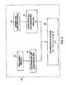
- FIG. 2is a simplified block diagram illustrating the fault-tolerant control system of the present invention.
- FIG. 3is a flow-chart illustrating a fault-tolerant mode selection procedure of the present invention.
- FIG. 4is a flow-chart illustrating an exemplary fault-correction algorithm of the present invention.
- FIG. 5is a diagram illustrating exemplary pre-set parameters for phase current modification in a fault-correction mode of the present invention.
- FIGS. 6A and 6Bare diagrams illustrating phase current modification in the fault-correction mode.
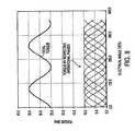
- FIGS. 7 , 8 and 9are diagrams illustrating torque produced by each phase to achieve total torque of the motor.
- FIG. 1is an exemplary view showing rotor and stator elements of a motor 10 as described in that application, the disclosure of which has been incorporated herein.
- Rotor member 20is an annular ring structure having permanent magnets 21 substantially evenly distributed along cylindrical back plate 25 .
- the permanent magnetsare rotor poles that alternate in magnetic polarity along the inner periphery of the annular ring.
- the rotorsurrounds a stator member 30 , the rotor and stator members being separated by an annular radial air gap.
- Stator 30comprises a plurality of electromagnet core segments of uniform construction that are evenly distributed along the air gap.
- Each core segmentcomprises a generally U-shaped magnetic structure 36 that forms two poles having surfaces 32 facing the air gap.
- the legs of the pole pairsare wound with windings 38 , although the core segment may be constructed to accommodate a single winding formed on a portion linking the pole pair.
- Each stator electromagnet core structureis separate, and magnetically isolated, from adjacent stator core elements.
- the stator elements 36are secured to a non-magnetically permeable support structure, thereby forming an annular ring configuration. This configuration eliminates emanation of stray transformer flux effects from adjacent stator pole groups.
- the stator electromagnetsare thus autonomous units comprising respective stator phases.
- the concepts of the invention described beloware also applicable to other permanent magnet motor structures, including a unitary stator core that supports all of the phase windings.
- FIG. 2is a block diagram of a motor control system in accordance with the present invention.
- the control systemincludes controller 210 for controlling multiphase motor 10 that comprises rotor 20 and stator 30 shown FIG. 1 .
- the statorhas a plurality of phase windings that are switchably energized by driving currents supplied by power electronic (PE) circuits 220 .
- PEpower electronic
- FIG. 2shows PE circuits 220 - 1 to 220 - 7 provided for seven stator phase windings.
- the present inventionis applicable to any number of motor phases.
- Each PE circuitmay include an electronic switch set controlled by controller 210 via a driver element.
- the switch setsmay comprise a plurality of MOSFET H-Bridges, such as International Rectifier IRFIZ48N-ND.
- the gate drivermay comprise Intersil MOSFET gate driver HIP4082IB.
- the controller 210has one or more user inputs and a plurality of inputs for motor conditions sensed during operation. Current in each phase winding is sensed by a respective one of a plurality of current sensors 230 whose outputs are provided to the controller 210 .
- the controllermay have a plurality of inputs for this purpose or, in the alternative, signals from the current sensors may be multiplexed and connected to a single controller input. Hall effect current sensors, such as F. W. Bell SM-15, may be utilized for currents sensors 230 .
- Rotor position sensor 240is connected to another input of the controller 210 to provide position signals thereto.
- the position sensormay comprise any known sensing means, such as a Hall effect devices (Allegro Microsystems 92B5308), giant magneto resistive (GMR) sensors, capacitive rotary sensors, reed switches, pulse wire sensors including amorphous sensors, resolvers, optical sensors and the like.
- the output of the position sensor 240may be applied to a speed approximator 242 , which converts the position signals to speed signals to be applied to another input of the controller 210 .
- Vi(t)is the voltage across the phase winding
- Idi (t)is the desired phase current to be produced to obtain desired torque
- Riis the winding resistance
- Liis the winding self-inductance
- the control voltage Vi (t) at the output of the controller 210represents a calculated voltage value required to obtain the user's requested torque.
- the controller 210defines phase current Idi (t) in each phase required to obtain the desired torque, and produces control signals Vi (t) for each phase based on the expression presented above.
- the control signals Vi (t)are successively supplied to the PE circuits 220 for individual energization of respective phase windings. Via the gate drivers, switch sets in the respective PE circuits 220 are activated so that the sequence in which windings are selected comports with a sequence established in the controller.
- Each successive control signal Vi (t)is related to the particular current sensed in the corresponding phase winding.
- the controller operationis disclosed in more detail in the copending U.S. application Ser. No. 10/173,610 of Maslov et al., filed Jun. 19, 2002 and incorporated herewith by reference
- the controller 210includes a fault-tolerant mode selector 250 for selecting a mode of fault-tolerant operations performed when at least one phase of the motor 10 fails.
- the fault-tolerant mode selector 250may be a register or an electronic circuit programmable by the user or controllable in accordance with motor conditions. Alternatively, the mode selector 250 may be arranged outside the controller 210 . As described in more detail below, in the event of a phase failure, the fault-tolerant mode selector 250 enables the controller 210 to operate in one of the following fault-tolerant modes of operation: non-correction mode and fault-correction mode.
- the controller 210does not modify the phase currents Idi (t) in the remaining phases of the motor 10 . Instead, it may control the PE circuit 220 corresponding to the failed phase so as to disable energization of the respective phase winding.
- the controller 210interacts with a fault-correction unit 260 to modify the phase currents Idi (t) in the phases that remain operational in accordance with a prescribed fault-correction algorithm.
- the fault correction unit 260may comprise a look-up table containing a predetermined set of parameters for modifying the phase currents Idi (t) in the phases that remain operational. As described below, this set of parameters may be customized in accordance with user's preferences.
- FIG. 3is a simplified flow-chart illustrating fault-tolerant operation of the motor control system of the present invention.
- the controller 210monitors its inputs to detect a failure of a motor phase (step 302 ). For example, a phase failure may be detected using current sensors 230 that measure phase current Ii(t) for each phase of the motor. If any current sensor 230 detects abnormal value of phase current Ii(t) for a predetermined period of time, the controller 210 detects a phase failure condition and identify a failed phase (step 304 ).
- phase current Ii(t) for a phasesuddenly drops to zero and does not return to its normal trajectory for a predetermined time period
- the controller 210determines that the circuit for the respective phase is open. Further, if phase current Ii(t) for a phase suddenly increases over a pre-set limit and does not return to its normal trajectory for a predetermined time period, the controller 210 determines that the circuit for the respective phase is shorted.
- the controller 210may monitor a phase current error for the respective phase.
- the phase current erroris a difference between the desired phase current Idi(t) and the actual phase current Ii(t) measured by the respective current sensor.
- the desired phase current Idi (t) for each phaseis defined by the controller 210 in accordance with a torque requirement, based on the position and speed determined by the position sensor 240 and the speed approximator 242 .
- the controller 210considers any phase to be a failed phase, if the absolute value of a phase current error for that phase exceeds a pre-set limit for a predetermined time period.
- the controller 210checks the fault-tolerant mode selector 250 to establish a prescribed fault-tolerant mode of operation (step 306 ).
- the mode selector 250may be pre-programmed by the user to request the controller 210 to operate either in a non-correction mode or in a fault correction mode if a phase failure condition is detected.
- the mode selector 250may be automatically controlled to select an appropriate fault-tolerant mode of operation depending on motor conditions at the time when a phase failure is detected. For example, when at least one phase fails, the mode selector 250 may be controlled to set a non-correction mode of operation, if phase currents Ii(t) for a predetermined number of remaining phases exceed a threshold level. In this case, modification of phase current values for the remaining phases would reduce the total torque value of the motor. In certain situations, the total torque reduction may be undesirable.
- the controller 210may compare phase current values detected by the current sensors 230 for the remaining phases with a threshold level. If the phase current values for a predetermined number of phases exceed the threshold level, the controller 210 controls the mode selector 250 to set a non-correction mode. Otherwise, a fault-correction mode may be set.
- the controller 210determines that the fault-correction mode is not set, it switches into the non-correction mode of operation (step 308 ).
- the controller 210may control the PE circuit 220 corresponding to the failed phase to disable energization of the respective phase winding.
- motor parameters relating to the phases that remain operational, including respective phase currents,are not modified despite a phase failure.
- step 306the controller 210 determines that the fault-correction mode is set, it switches into the fault-correction mode of operation (step 310 ). In the fault-correction mode, the controller 210 modifies the desired phase currents Idi (t) in the phases that remain operational in accordance with a prescribed fault-correction algorithm.
- FIG. 4illustrates an exemplary fault-correction algorithm that may be carried out in the fault-correction mode of operation.
- the controller 210identifies failed phase j (step 312 ), and computes a phase angle offset or distance Djk between the failed phase j and each of phases k that remain operational (step 314 ), where j and k are integral numbers from 1 to Ns, and Ns is the number of phases in the motor 10 .
- the controller 210obtains values of torque ⁇ requested by the user and motor speed ⁇ determined by the speed approximator 242 (step 316 ). These values are used as indexes for accessing a fault-correction look-up table contained in the fault correction unit 260 .
- the fault-correction look-up tablecontains parameters I 1 and I 2 utilized for calculation of a desired phase current magnitude for each of the remaining phases k.
- Parameter I 1represents the maximum current magnitude at a phase location arranged at a predetermined phase angle with respect to the failed phase j. For example, the maximum current magnitude may be at a phase location corresponding to the failed phase j.
- Parameter I 2represents the minimum current magnitude at a phase angle shifted by 90 degrees from the phase location of the maximum current magnitude.
- parameters I 1 and I 2are provided for various combinations of requested torque and present speed.
- FIG. 5is a diagram illustrating the fault-correction algorithm that involves modification of phase currents in accordance with parameters I 1 and I 2 .
- parameter I 1may represent the phase current magnitude at a phase corresponding to the failed phase j
- parameter 12may represent the phase current magnitude at a phase angle shifted by 90 degrees with respect to the failed phase j.
- the controller 210modifies a phase current magnitude for a phase, which are closer to the failed phase j, to make it higher than a phase current magnitude for a phase, which are more distant from the failed phase j.
- modified phase current magnitude for phase j ⁇ 1which is the closest phase to the failed phase j
- modified phase current magnitude for the next phase j ⁇ 2which in turn is higher than modified phase current magnitude for phase j-(Ns ⁇ 1)/2, the most distant phase from the failed phase j.
- Magnitude I 0is a phase current value in each phase before the failure of the phase j.
- FIGS. 6A and 6Bare diagrams respectively showing phase currents in a seven-phase motor without fault correction and with fault correction in accordance with the fault-correction algorithm of the present invention. These diagrams illustrate the case when phase 3 fails, and the phase current for phase 3 is set to 0. Without fault correction, phase currents for phases 1 , 2 and 4 - 7 , which remain operational, have magnitude I 0 set, for example, to 10 A (FIG. 6 A). With fault correction, the controller 210 sets magnitudes of phase currents for operational phases 1 , 2 and 4 - 7 in the range between I 1 and I 2 . For example, I 1 may be set to 12 A and I 2 may be set to 5 A.
- FIG. 7is a diagram showing torque produced by each phase, i.e. torque contribution from each phase of a seven-phase motor in a normal mode of operation for sine-wave profile of phase currents. As all phases are operational, total torque for all phases equal, for example, to 35 Nm may have practically no ripples
- FIG. 8is a diagram showing torque contribution from each of operational phases 1 , 2 and 4 - 7 , when phase 3 fails but phase currents for the remaining phases are not modified. As illustrated in this diagram, the failure of a phase cause a substantial torque ripple equal, for example, to 0.17 for total torque varying between 25 to 35 Nm.
- FIG. 9is a diagram illustrating torque contribution from each of operational phases 1 , 2 and 4 - 7 , when phase 3 fails and phase currents for remaining phases are re-distributed in accordance with a fault-correction algorithm of the present invention. As shown in this diagram, torque ripple may be reduced to about 0.04 for total torque varying between 23 and 25 Nm.
- fault-correction unit 260may contain several sets of fault correction parameters I 1 and I 2 for each combination of torque and speed.
- parameter I 2should be selected to be at a level of parameter I 1 .
- both these parametersshould be set to the maximum possible current value.
- torque rippleAs a result, the motor may become unbalanced.
- an optimum difference between values of parameters I 1 and I 2may be experimentally established.
- the motor controlled by the control system of the present inventiondoes not need redundant elements in order to continue its operation when a phase fails.
- the control systemgives the user high flexibility by enabling motor fault-tolerant operations with or without fault correction depending on user's preferences and motor conditions.
- fault-correction parameters defining motor characteristics when a phase is lostmay be customized in accordance with user's preferences.
Landscapes
- Engineering & Computer Science (AREA)
- Power Engineering (AREA)
- Control Of Motors That Do Not Use Commutators (AREA)
Abstract
Description
Vi(t)=LidIdi/dt+Ri Ii+Ei+ksiei
where
Claims (22)
Ik=I1−(I1−I2)×Djk/90 degrees
Priority Applications (9)
| Application Number | Priority Date | Filing Date | Title |
|---|---|---|---|
| US10/678,133US6949908B2 (en) | 2003-10-06 | 2003-10-06 | Fault-tolerant electric motor control system |
| EP04782482AEP1671416A1 (en) | 2003-10-06 | 2004-08-27 | Fault-tolerant electric motor control system |
| KR1020067006670AKR20060120657A (en) | 2003-10-06 | 2004-08-27 | Electric motor control system with error resistance |
| CNA2004800356059ACN1886887A (en) | 2003-10-06 | 2004-08-27 | Fault-tolerant electric motor control system |
| JP2006533861AJP2007507998A (en) | 2003-10-06 | 2004-08-27 | Fault-tolerant electric motor control system |
| AU2004307711AAU2004307711A1 (en) | 2003-10-06 | 2004-08-27 | Fault-tolerant electric motor control system |
| CA002542424ACA2542424A1 (en) | 2003-10-06 | 2004-08-27 | Fault-tolerant electric motor control system |
| PCT/US2004/028010WO2005041401A1 (en) | 2003-10-06 | 2004-08-27 | Fault-tolerant electric motor control system |
| TW093128362ATW200524266A (en) | 2003-10-06 | 2004-09-20 | Fault-tolerant electric motor control system |
Applications Claiming Priority (1)
| Application Number | Priority Date | Filing Date | Title |
|---|---|---|---|
| US10/678,133US6949908B2 (en) | 2003-10-06 | 2003-10-06 | Fault-tolerant electric motor control system |
Publications (2)
| Publication Number | Publication Date |
|---|---|
| US20050073273A1 US20050073273A1 (en) | 2005-04-07 |
| US6949908B2true US6949908B2 (en) | 2005-09-27 |
Family
ID=34393869
Family Applications (1)
| Application Number | Title | Priority Date | Filing Date |
|---|---|---|---|
| US10/678,133Expired - Fee RelatedUS6949908B2 (en) | 2003-10-06 | 2003-10-06 | Fault-tolerant electric motor control system |
Country Status (9)
| Country | Link |
|---|---|
| US (1) | US6949908B2 (en) |
| EP (1) | EP1671416A1 (en) |
| JP (1) | JP2007507998A (en) |
| KR (1) | KR20060120657A (en) |
| CN (1) | CN1886887A (en) |
| AU (1) | AU2004307711A1 (en) |
| CA (1) | CA2542424A1 (en) |
| TW (1) | TW200524266A (en) |
| WO (1) | WO2005041401A1 (en) |
Cited By (18)
| Publication number | Priority date | Publication date | Assignee | Title |
|---|---|---|---|---|
| US20050007051A1 (en)* | 2003-06-13 | 2005-01-13 | Andras Lelkes | Method for the commutation of a brushless direct current motor |
| US20050241875A1 (en)* | 2004-04-30 | 2005-11-03 | Nsk Ltd. | Control device of electric power steering apparatus |
| US20050264254A1 (en)* | 2004-05-26 | 2005-12-01 | Lequesne Bruno P B | Switched reluctance motor control with partially disabled operation capability |
| US20060061923A1 (en)* | 2004-09-20 | 2006-03-23 | Zheng Wang | Power converter controlling apparatus and method applying a fault protection scheme in a motor drive system |
| US20080238217A1 (en)* | 2007-03-28 | 2008-10-02 | General Electric Company | Fault-tolerant permanent magnet machine with reconfigurable flux paths in stator back iron |
| US20080238220A1 (en)* | 2007-03-28 | 2008-10-02 | General Electric Company | Fault-tolerant permanent magnet machine with reconfigurable stator core slot flux paths |
| US20080238233A1 (en)* | 2007-03-28 | 2008-10-02 | General Electric Company | Fault-tolerant permanent magnet machine with reconfigurable stator core slot opening and back iron flux paths |
| US20100021313A1 (en)* | 2008-07-28 | 2010-01-28 | Eaton Corporation | Electronic control for a rotary fluid device |
| US20110278099A1 (en)* | 2009-03-05 | 2011-11-17 | Ari Kattainen | Elevator system |
| US20130193895A1 (en)* | 2010-07-26 | 2013-08-01 | Mitsubishi Electric Corporation | Motor control apparatus and control method thereof |
| US20140042952A1 (en)* | 2012-08-09 | 2014-02-13 | Samsung Electro-Mechanics Co., Ltd. | Apparatus and method for preventing sensing error in srm |
| US20150015174A1 (en)* | 2013-07-12 | 2015-01-15 | The Boeing Company | Active-active redundant motor gear system |
| EP2852050A1 (en) | 2013-09-18 | 2015-03-25 | Sociéte Anonyme Belge de Constructions Aéronautiques, S.A.B.C.A. | Method and device for generating n (n >= 3) control signals for controlling an inverter with n phases |
| US9242564B2 (en)* | 2011-07-11 | 2016-01-26 | Magna Powertrain Ag & Co Kg | Converter for an electrical machine, controller and method for operating a converter |
| US9278751B2 (en) | 2011-04-07 | 2016-03-08 | Airbus Operations Gmbh | High lift system for an aircraft |
| US10988030B2 (en) | 2014-09-26 | 2021-04-27 | Francis Xavier Gentile | Electric motor, generator and battery combination |
| US11296644B2 (en)* | 2020-01-20 | 2022-04-05 | Ford Global Technologies, Llc | Alternating passive rectification and 3-phase-short control for motor fault protection |
| US20220286077A1 (en)* | 2019-08-26 | 2022-09-08 | Moog Inc. | Fault tolerant actuator assembly |
Families Citing this family (42)
| Publication number | Priority date | Publication date | Assignee | Title |
|---|---|---|---|---|
| US7002318B1 (en)* | 2004-09-23 | 2006-02-21 | General Motors Corporation | Position sensor fault tolerant control for automotive propulsion system |
| RU2311721C1 (en)* | 2006-08-04 | 2007-11-27 | Государственное образовательное учреждение высшего профессионального образования Томский политехнический университет | Method for maintaining durability of three-phase valve motor |
| CN100459407C (en)* | 2007-03-14 | 2009-02-04 | 南京航空航天大学 | Bearingless switched reluctance motor error-tolerant operation control method |
| US8278862B2 (en)* | 2009-07-10 | 2012-10-02 | Won-Door Corporation | Motor control systems, foldable partitions employing motor control systems, methods of monitoring the operation of electric motors and foldable partitions |
| RU2401500C1 (en)* | 2009-08-28 | 2010-10-10 | Государственное образовательное учреждение высшего профессионального образования "Южно-Уральский государственный университет" | Method for providing survivability of polyphase thyratron motor |
| CN102004224B (en)* | 2009-08-31 | 2012-12-12 | 比亚迪股份有限公司 | Three-phase motor phase failure detection system and detection method thereof |
| CN101662256B (en)* | 2009-09-21 | 2012-08-22 | 南京航空航天大学 | Control method of six-phase ten-pole permanent magnet fault-tolerant motor with strong fault tolerance |
| CN101662257B (en)* | 2009-09-21 | 2012-08-22 | 南京航空航天大学 | Simple and optimal current direct control method of multiphase permanent magnet fault-tolerant electric machine |
| JP4831503B2 (en)* | 2009-09-30 | 2011-12-07 | 株式会社デンソー | Control device for multi-phase rotating machine and electric power steering device using the same |
| JP5387989B2 (en)* | 2009-12-25 | 2014-01-15 | 株式会社デンソー | Electric motor drive device and electric power steering device using the same |
| GB201000476D0 (en) | 2010-01-13 | 2010-03-03 | Rolls Royce Plc | A fault tolerant electrical machine |
| CN101783563B (en)* | 2010-03-10 | 2012-05-23 | 江苏大学 | Multiple multiphase fault-tolerant motors for electric automobile and decoupling control method thereof |
| RU2435291C1 (en)* | 2010-08-26 | 2011-11-27 | Государственное образовательное учреждение высшего профессионального образования "Национальный исследовательский Томский политехнический университет" | Method to ensure durability of three-phase valve motor based on salient-pole synchronous machine |
| JP5577506B2 (en) | 2010-09-14 | 2014-08-27 | ソーラテック コーポレイション | Centrifugal pump device |
| US9906018B2 (en)* | 2011-01-20 | 2018-02-27 | Triune Systems, LLC | Electrical line status monitoring system |
| EP2693609B1 (en) | 2011-03-28 | 2017-05-03 | Thoratec Corporation | Rotation and drive device and centrifugal pump device using same |
| US8837096B2 (en) | 2012-03-13 | 2014-09-16 | Thoratec Corporation | Fault monitor for fault tolerant implantable pump |
| CN103378778B (en)* | 2012-04-28 | 2016-01-20 | 广东高标电子科技有限公司 | A kind of electric motor car, brshless DC motor and driving control system thereof |
| CN102780447A (en)* | 2012-08-18 | 2012-11-14 | 天津市松正电动汽车技术股份有限公司 | Single-power source six-phase motor drive system |
| CN102780427B (en)* | 2012-08-20 | 2015-07-08 | 天津市松正电动汽车技术股份有限公司 | Six-phase motor driving system |
| US8968174B2 (en) | 2013-01-16 | 2015-03-03 | Thoratec Corporation | Motor fault monitor for implantable blood pump |
| US9371826B2 (en) | 2013-01-24 | 2016-06-21 | Thoratec Corporation | Impeller position compensation using field oriented control |
| RU2525300C1 (en)* | 2013-02-08 | 2014-08-10 | Общество с ограниченной ответственностью "ДОНА-М" | Method to control three-phase valve electric motor of implanted rotary electric pump of cardioprosthesis with provision of liveness property (versions) |
| US9556873B2 (en) | 2013-02-27 | 2017-01-31 | Tc1 Llc | Startup sequence for centrifugal pump with levitated impeller |
| GB201306565D0 (en) | 2013-04-11 | 2013-05-22 | Rolls Royce Plc | Aircraft Electrical System Operating Method |
| US10052420B2 (en) | 2013-04-30 | 2018-08-21 | Tc1 Llc | Heart beat identification and pump speed synchronization |
| DE102013222007A1 (en) | 2013-10-30 | 2015-02-19 | Zf Friedrichshafen Ag | A processor, apparatus, method and computer program for controlling an emergency operation of a multiphase induction machine upon interruption of a first phase current of a first phase of the induction machine |
| US20150270747A1 (en)* | 2014-03-24 | 2015-09-24 | The Texas A&M University System | System and method for controlling multiphase electric motors |
| US9623161B2 (en) | 2014-08-26 | 2017-04-18 | Tc1 Llc | Blood pump and method of suction detection |
| KR101646210B1 (en) | 2014-09-23 | 2016-08-05 | 국민대학교산학협력단 | Motor control system for considering functional safety |
| CN104467566B (en)* | 2014-12-08 | 2017-01-25 | 中国矿业大学 | Switch reluctance machine position sensor fault-tolerant control method |
| EP3256183B1 (en) | 2015-02-11 | 2025-08-13 | Tc1 Llc | Heart beat identification and pump speed synchronization |
| EP3256185B1 (en) | 2015-02-12 | 2019-10-30 | Tc1 Llc | System and method for controlling the position of a levitated rotor |
| US10371152B2 (en) | 2015-02-12 | 2019-08-06 | Tc1 Llc | Alternating pump gaps |
| EP3256184B1 (en) | 2015-02-13 | 2020-04-08 | Tc1 Llc | Impeller suspension mechanism for heart pump |
| EP3118638B1 (en)* | 2015-06-25 | 2019-08-07 | ABB Schweiz AG | Temperature estimation in power semiconductor device in electric drive system |
| US9601003B2 (en)* | 2015-08-17 | 2017-03-21 | Hamilton Sundstrand Space Systems International, Inc. | Sensor and control systems for electrical machines |
| US10117983B2 (en) | 2015-11-16 | 2018-11-06 | Tc1 Llc | Pressure/flow characteristic modification of a centrifugal pump in a ventricular assist device |
| FR3061370B1 (en)* | 2016-12-27 | 2022-05-13 | Francecol Tech | ELECTROMAGNETIC ASSEMBLY WITH POLYPHASE STRUCTURE |
| CN111133658B (en)* | 2017-08-30 | 2022-07-12 | 鲲腾科技公司 | Motor system and control method |
| NL2020150B1 (en)* | 2017-12-21 | 2019-07-01 | Saluqi Holding B V | A Switched Reluctance Motor, SRM, system with short flux path. |
| WO2019227118A1 (en)* | 2018-05-31 | 2019-12-05 | Newsouth Innovations Pty Ltd | A machine, stator and method for design and optimisation |
Citations (18)
| Publication number | Priority date | Publication date | Assignee | Title |
|---|---|---|---|---|
| US3961688A (en)* | 1974-04-29 | 1976-06-08 | Armor Elevator Company | Transportation system with malfunction monitor |
| US4434389A (en) | 1980-10-28 | 1984-02-28 | Kollmorgen Technologies Corporation | Motor with redundant windings |
| US5357181A (en)* | 1992-10-13 | 1994-10-18 | Hitachi, Ltd. | Failure detection method for electric vehicles and fail-safe control method using this method |
| US5436545A (en)* | 1992-12-17 | 1995-07-25 | International Business Machines Corporation | System for accurately measuring current in PWM amplifier driven loads |
| US5457374A (en)* | 1993-08-24 | 1995-10-10 | Alliedsignal Inc. | Motor controller for operating an inverter in current-controlled and voltage-controlled modes |
| US5491622A (en)* | 1994-01-07 | 1996-02-13 | Delco Electronics Corp. | Power converter with emergency operating mode for three phase induction motors |
| US5694010A (en)* | 1994-06-14 | 1997-12-02 | Kabushiki Kaisha Toshiba | Method and apparatus for controlling a brushless DC motor |
| US5793623A (en)* | 1994-07-01 | 1998-08-11 | Sharp Kabushiki Kaisha | Air conditioning device |
| US5814957A (en)* | 1996-02-14 | 1998-09-29 | Matsushita Electric Industrial Co., Ltd. | Direct current brushless motor and driving method therefor |
| US6054827A (en)* | 1997-01-23 | 2000-04-25 | Mitsubishi Denki Kabushiki Kaisha | Controller for motor-driven power steering |
| EP1050425A2 (en) | 1999-05-07 | 2000-11-08 | Honda Giken Kogyo Kabushiki Kaisha | Failure detection system for a propulsion system |
| WO2001097355A1 (en) | 2000-06-09 | 2001-12-20 | International Rectifier Corporation | Dynamic motor drive torque control based on power switching device temperature feedback |
| US6389373B1 (en)* | 1998-08-05 | 2002-05-14 | Toyota Jidosha Kabushiki Kaisha | Resolver signal processing system |
| US20020117990A1 (en)* | 2001-02-27 | 2002-08-29 | Hitachi Ltd. | Motor control apparatus and electric vehicle using same |
| US6611771B1 (en)* | 2000-10-04 | 2003-08-26 | Eaton Corporation | Method and apparatus to detect a stator turn fault in an AC motor |
| US6677724B1 (en)* | 1999-09-17 | 2004-01-13 | Kabushiki Kaisha Yaskawa Denki | Initial magnetic pole estimating device for AC synchronous motor |
| US6683435B1 (en)* | 2002-06-21 | 2004-01-27 | Ford Motor Company | Electrical machine drive method and system |
| US20040085787A1 (en)* | 2000-01-24 | 2004-05-06 | Perreault David J. | Load matched alternator system with fault protection |
Family Cites Families (3)
| Publication number | Priority date | Publication date | Assignee | Title |
|---|---|---|---|---|
| JPS55111691A (en)* | 1979-02-19 | 1980-08-28 | Hitachi Ltd | Device for controlling operation of ac motor |
| US4896089A (en)* | 1989-01-31 | 1990-01-23 | General Electric Company | Fault management system for a switched reluctance motor |
| JP2000287493A (en)* | 1999-03-30 | 2000-10-13 | Matsushita Electric Ind Co Ltd | Motor protection device |
- 2003
- 2003-10-06USUS10/678,133patent/US6949908B2/ennot_activeExpired - Fee Related
- 2004
- 2004-08-27WOPCT/US2004/028010patent/WO2005041401A1/enactiveApplication Filing
- 2004-08-27JPJP2006533861Apatent/JP2007507998A/enactivePending
- 2004-08-27KRKR1020067006670Apatent/KR20060120657A/ennot_activeWithdrawn
- 2004-08-27AUAU2004307711Apatent/AU2004307711A1/ennot_activeAbandoned
- 2004-08-27CACA002542424Apatent/CA2542424A1/ennot_activeAbandoned
- 2004-08-27EPEP04782482Apatent/EP1671416A1/ennot_activeWithdrawn
- 2004-08-27CNCNA2004800356059Apatent/CN1886887A/enactivePending
- 2004-09-20TWTW093128362Apatent/TW200524266A/enunknown
Patent Citations (19)
| Publication number | Priority date | Publication date | Assignee | Title |
|---|---|---|---|---|
| US3961688A (en)* | 1974-04-29 | 1976-06-08 | Armor Elevator Company | Transportation system with malfunction monitor |
| US4434389A (en) | 1980-10-28 | 1984-02-28 | Kollmorgen Technologies Corporation | Motor with redundant windings |
| US5357181A (en)* | 1992-10-13 | 1994-10-18 | Hitachi, Ltd. | Failure detection method for electric vehicles and fail-safe control method using this method |
| US5436545A (en)* | 1992-12-17 | 1995-07-25 | International Business Machines Corporation | System for accurately measuring current in PWM amplifier driven loads |
| US5457374A (en)* | 1993-08-24 | 1995-10-10 | Alliedsignal Inc. | Motor controller for operating an inverter in current-controlled and voltage-controlled modes |
| US5491622A (en)* | 1994-01-07 | 1996-02-13 | Delco Electronics Corp. | Power converter with emergency operating mode for three phase induction motors |
| US6153993A (en)* | 1994-06-14 | 2000-11-28 | Kabushiki Kaisha Toshiba | Method and apparatus for controlling a brushless DC motor that indicates a motor failure |
| US5694010A (en)* | 1994-06-14 | 1997-12-02 | Kabushiki Kaisha Toshiba | Method and apparatus for controlling a brushless DC motor |
| US5793623A (en)* | 1994-07-01 | 1998-08-11 | Sharp Kabushiki Kaisha | Air conditioning device |
| US5814957A (en)* | 1996-02-14 | 1998-09-29 | Matsushita Electric Industrial Co., Ltd. | Direct current brushless motor and driving method therefor |
| US6054827A (en)* | 1997-01-23 | 2000-04-25 | Mitsubishi Denki Kabushiki Kaisha | Controller for motor-driven power steering |
| US6389373B1 (en)* | 1998-08-05 | 2002-05-14 | Toyota Jidosha Kabushiki Kaisha | Resolver signal processing system |
| EP1050425A2 (en) | 1999-05-07 | 2000-11-08 | Honda Giken Kogyo Kabushiki Kaisha | Failure detection system for a propulsion system |
| US6677724B1 (en)* | 1999-09-17 | 2004-01-13 | Kabushiki Kaisha Yaskawa Denki | Initial magnetic pole estimating device for AC synchronous motor |
| US20040085787A1 (en)* | 2000-01-24 | 2004-05-06 | Perreault David J. | Load matched alternator system with fault protection |
| WO2001097355A1 (en) | 2000-06-09 | 2001-12-20 | International Rectifier Corporation | Dynamic motor drive torque control based on power switching device temperature feedback |
| US6611771B1 (en)* | 2000-10-04 | 2003-08-26 | Eaton Corporation | Method and apparatus to detect a stator turn fault in an AC motor |
| US20020117990A1 (en)* | 2001-02-27 | 2002-08-29 | Hitachi Ltd. | Motor control apparatus and electric vehicle using same |
| US6683435B1 (en)* | 2002-06-21 | 2004-01-27 | Ford Motor Company | Electrical machine drive method and system |
Cited By (29)
| Publication number | Priority date | Publication date | Assignee | Title |
|---|---|---|---|---|
| US7145303B2 (en)* | 2003-06-13 | 2006-12-05 | Minebea Co. Ltd. | Method for the commutation of a brushless direct current motor |
| US20050007051A1 (en)* | 2003-06-13 | 2005-01-13 | Andras Lelkes | Method for the commutation of a brushless direct current motor |
| US20050241875A1 (en)* | 2004-04-30 | 2005-11-03 | Nsk Ltd. | Control device of electric power steering apparatus |
| US20050264254A1 (en)* | 2004-05-26 | 2005-12-01 | Lequesne Bruno P B | Switched reluctance motor control with partially disabled operation capability |
| US7095206B2 (en)* | 2004-05-26 | 2006-08-22 | Delphi Technologies, Inc. | Switched reluctance motor control with partially disabled operation capability |
| US7375934B2 (en)* | 2004-09-20 | 2008-05-20 | Honeywell International Inc. | Power converter controlling apparatus and method applying a fault protection scheme in a motor drive system |
| US20060061923A1 (en)* | 2004-09-20 | 2006-03-23 | Zheng Wang | Power converter controlling apparatus and method applying a fault protection scheme in a motor drive system |
| US20080238217A1 (en)* | 2007-03-28 | 2008-10-02 | General Electric Company | Fault-tolerant permanent magnet machine with reconfigurable flux paths in stator back iron |
| US20080238220A1 (en)* | 2007-03-28 | 2008-10-02 | General Electric Company | Fault-tolerant permanent magnet machine with reconfigurable stator core slot flux paths |
| US20080238233A1 (en)* | 2007-03-28 | 2008-10-02 | General Electric Company | Fault-tolerant permanent magnet machine with reconfigurable stator core slot opening and back iron flux paths |
| US7541705B2 (en) | 2007-03-28 | 2009-06-02 | General Electric Company | Fault-tolerant permanent magnet machine with reconfigurable flux paths in stator back iron |
| US7605504B2 (en) | 2007-03-28 | 2009-10-20 | General Electric Company | Fault-tolerant permanent magnet machine with reconfigurable stator core slot flux paths |
| US7605503B2 (en) | 2007-03-28 | 2009-10-20 | General Electric Company | Fault-tolerant permanent magnet machine with reconfigurable stator core slot opening and back iron flux paths |
| US10100827B2 (en) | 2008-07-28 | 2018-10-16 | Eaton Intelligent Power Limited | Electronic control for a rotary fluid device |
| US20100021313A1 (en)* | 2008-07-28 | 2010-01-28 | Eaton Corporation | Electronic control for a rotary fluid device |
| US20110278099A1 (en)* | 2009-03-05 | 2011-11-17 | Ari Kattainen | Elevator system |
| US8235180B2 (en)* | 2009-03-05 | 2012-08-07 | Kone Corporation | Elevator system with a brake control circuit using a controllable switch switched with short pulses |
| US20130193895A1 (en)* | 2010-07-26 | 2013-08-01 | Mitsubishi Electric Corporation | Motor control apparatus and control method thereof |
| US9278751B2 (en) | 2011-04-07 | 2016-03-08 | Airbus Operations Gmbh | High lift system for an aircraft |
| US9242564B2 (en)* | 2011-07-11 | 2016-01-26 | Magna Powertrain Ag & Co Kg | Converter for an electrical machine, controller and method for operating a converter |
| US20140042952A1 (en)* | 2012-08-09 | 2014-02-13 | Samsung Electro-Mechanics Co., Ltd. | Apparatus and method for preventing sensing error in srm |
| US20150015174A1 (en)* | 2013-07-12 | 2015-01-15 | The Boeing Company | Active-active redundant motor gear system |
| US9124150B2 (en)* | 2013-07-12 | 2015-09-01 | The Boeing Company | Active-active redundant motor gear system |
| EP2852050A1 (en) | 2013-09-18 | 2015-03-25 | Sociéte Anonyme Belge de Constructions Aéronautiques, S.A.B.C.A. | Method and device for generating n (n >= 3) control signals for controlling an inverter with n phases |
| US10988030B2 (en) | 2014-09-26 | 2021-04-27 | Francis Xavier Gentile | Electric motor, generator and battery combination |
| US12024050B2 (en) | 2014-09-26 | 2024-07-02 | Francis Xavier Gentile | Electric motor, generator and battery combination |
| US20220286077A1 (en)* | 2019-08-26 | 2022-09-08 | Moog Inc. | Fault tolerant actuator assembly |
| US12015365B2 (en)* | 2019-08-26 | 2024-06-18 | Moog Inc. | Fault tolerant actuator assembly |
| US11296644B2 (en)* | 2020-01-20 | 2022-04-05 | Ford Global Technologies, Llc | Alternating passive rectification and 3-phase-short control for motor fault protection |
Also Published As
| Publication number | Publication date |
|---|---|
| EP1671416A1 (en) | 2006-06-21 |
| KR20060120657A (en) | 2006-11-27 |
| CA2542424A1 (en) | 2005-05-06 |
| WO2005041401A1 (en) | 2005-05-06 |
| TW200524266A (en) | 2005-07-16 |
| US20050073273A1 (en) | 2005-04-07 |
| CN1886887A (en) | 2006-12-27 |
| AU2004307711A1 (en) | 2005-05-06 |
| JP2007507998A (en) | 2007-03-29 |
Similar Documents
| Publication | Publication Date | Title |
|---|---|---|
| US6949908B2 (en) | Fault-tolerant electric motor control system | |
| JP3814624B2 (en) | Brushless motor control using independent phase parameters | |
| KR100420714B1 (en) | Transition magnetoresistive drive system, position transducer for 2-phase switching magnetoresistance machine and output control method of 2-phase switching magnetoresistance machine | |
| KR101336472B1 (en) | A method for discriminating the malfuncition of bldc motor control system | |
| AU2004208342A1 (en) | Phase advance angle optimization for brushless motor control | |
| EP0732801B1 (en) | Apparatus for starting a switched reluctance motor | |
| JP4633433B2 (en) | Method for commutation of brushless DC motor | |
| US9768649B2 (en) | Single-phase electric motor | |
| EP0732800B1 (en) | Switched reluctance motor provided with rotor position detection | |
| CA2168163C (en) | Switched reluctance motor providing rotor position detection at high speeds without a separate rotor shaft position sensor | |
| JP2006136194A (en) | Brushless dc motor | |
| KR20160032354A (en) | Apparatus for applying an electric current control of motor | |
| EP0653833B1 (en) | A brushless electric motor and a method for controlling the motor | |
| KR200170195Y1 (en) | Position sensing device of switched reluctance motor | |
| JP2000295890A (en) | Driving controller of brushless motor | |
| KR102298363B1 (en) | Apparatus for applying an electric current control of motor | |
| JP7340690B2 (en) | Control unit, electrical machine and method for driving an electrical machine | |
| JP3678598B2 (en) | Method and apparatus for driving motor for detecting rotor position using change in inductance of stator winding | |
| JP3243884B2 (en) | Brushless motor and its stopping method | |
| GB2266816A (en) | Speed/torque control of electric motors | |
| KR20250100943A (en) | Determining method for diagnose faults of bldc motor signal judgement device | |
| JP2011091886A (en) | Motor driver | |
| JPH05111286A (en) | Driver for brushless motor | |
| JPH09117184A (en) | Electronic motor | |
| JPH0723585A (en) | Brushless motor drive |
Legal Events
| Date | Code | Title | Description |
|---|---|---|---|
| AS | Assignment | Owner name:WAVECREST LABORATORIES, LLC, VIRGINIA Free format text:ASSIGNMENT OF ASSIGNORS INTEREST;ASSIGNORS:MASLOV, BORIS A.;YUAN, GUOHUI;REEL/FRAME:014583/0216 Effective date:20030930 | |
| AS | Assignment | Owner name:BLUWAV SYSTEMS LLC, MICHIGAN Free format text:ASSIGNMENT OF ASSIGNORS INTEREST;ASSIGNOR:WAVECREST LABORATORIES LLC;REEL/FRAME:020483/0785 Effective date:20071127 Owner name:BLUWAV SYSTEMS LLC,MICHIGAN Free format text:ASSIGNMENT OF ASSIGNORS INTEREST;ASSIGNOR:WAVECREST LABORATORIES LLC;REEL/FRAME:020483/0785 Effective date:20071127 | |
| FEPP | Fee payment procedure | Free format text:PAT HOLDER NO LONGER CLAIMS SMALL ENTITY STATUS, ENTITY STATUS SET TO UNDISCOUNTED (ORIGINAL EVENT CODE: STOL); ENTITY STATUS OF PATENT OWNER: LARGE ENTITY | |
| REFU | Refund | Free format text:REFUND - SURCHARGE, PETITION TO ACCEPT PYMT AFTER EXP, UNINTENTIONAL (ORIGINAL EVENT CODE: R2551); ENTITY STATUS OF PATENT OWNER: LARGE ENTITY | |
| REMI | Maintenance fee reminder mailed | ||
| FPAY | Fee payment | Year of fee payment:4 | |
| SULP | Surcharge for late payment | ||
| FPAY | Fee payment | Year of fee payment:8 | |
| REMI | Maintenance fee reminder mailed | ||
| LAPS | Lapse for failure to pay maintenance fees | Free format text:PATENT EXPIRED FOR FAILURE TO PAY MAINTENANCE FEES (ORIGINAL EVENT CODE: EXP.) | |
| STCH | Information on status: patent discontinuation | Free format text:PATENT EXPIRED DUE TO NONPAYMENT OF MAINTENANCE FEES UNDER 37 CFR 1.362 | |
| FP | Lapsed due to failure to pay maintenance fee | Effective date:20170927 |