US6949145B2 - Vapor-assisted cryogenic cleaning - Google Patents
Vapor-assisted cryogenic cleaningDownload PDFInfo
- Publication number
- US6949145B2 US6949145B2US10/403,147US40314703AUS6949145B2US 6949145 B2US6949145 B2US 6949145B2US 40314703 AUS40314703 AUS 40314703AUS 6949145 B2US6949145 B2US 6949145B2
- Authority
- US
- United States
- Prior art keywords
- reactant
- applying
- contaminant
- cryogenic
- vapor
- Prior art date
- Legal status (The legal status is an assumption and is not a legal conclusion. Google has not performed a legal analysis and makes no representation as to the accuracy of the status listed.)
- Expired - Lifetime
Links
Images


Classifications
- B—PERFORMING OPERATIONS; TRANSPORTING
- B08—CLEANING
- B08B—CLEANING IN GENERAL; PREVENTION OF FOULING IN GENERAL
- B08B7/00—Cleaning by methods not provided for in a single other subclass or a single group in this subclass
- B08B7/0064—Cleaning by methods not provided for in a single other subclass or a single group in this subclass by temperature changes
- B08B7/0092—Cleaning by methods not provided for in a single other subclass or a single group in this subclass by temperature changes by cooling
Definitions
- the present inventionrelates to the use of a reactive gas or vapor of a reactive liquid, with or without a free radical generator, and either simultaneously or sequentially, with cryogenic cleaning to aid in the removal of foreign materials (FM), e.g. particles, films, and other contaminants, from semiconductor surfaces and other surfaces involved in precision cleaning.
- FMforeign materials
- the demands for greater switching speed and circuit performancehave seen the advent of new dielectric materials (dielectric constant of ⁇ 3) and metals to reduce the RC delay constant in circuits.
- the metal of choicewhich is copper, has added several challenges to the process integration scheme.
- the metal patterningwas performed by reactive ion etching (RIE) of the aluminum followed by dielectric deposition.
- RIEreactive ion etching
- copperthe dielectric film is first deposited and etched to form vias and trenches followed by the deposition of copper in those etched features.
- CMPchemical mechanical polishing
- This method of forming copper interconnects for the back-end-of-line (BEOL)is known as the Dual Damascene process.
- cryogenic particlesFor cryogenic cleaning to work effectively in removing the sidewall residues from inside the features, as shown in FIG. 1 , the cryogenic particles must be less than 0.13 ⁇ m in size. As well, these particles must arrive at the surface of the wafer with enough velocity to impart the momentum transfer required to dislodge the sidewall residue.
- liquid CO 2 at a pressure of about 850 psi from a purified sourceis made to expand through the orifice of a specially designed nozzle intended to make the expansion a constant enthalpy process.
- the expansion of liquid CO 2 through the nozzlecreates solid and gaseous CO 2 in a highly directional and focused stream. Due to the gas flow over the wafer surface, a boundary layer is formed.
- the CO 2 cryogenic particlesmust travel through the boundary layer to arrive at the wafer surface and at the contaminant particle to be removed. During the flight through the boundary layer, their velocity decreases due to the drag force on them by the gaseous CO 2 in the boundary layer.
- a snow particlemust enter the layer with a normal component of velocity equal to at least h/t where t is the time taken to cross the boundary layer and arrive at the wafer surface.
- ⁇is the viscosity of the gas
- C cis the Cunningham slip correction factor given as in equation (2)
- C c1+1.246( ⁇ / a )+0.42( ⁇ / a )exp[ ⁇ 0.87( a / ⁇ )] (2)
- ⁇is the mean free path of gas molecules. Since the CO 2 cryogenic cleaning is conducted at atmospheric pressure, the Cunningham slip correction factor becomes equal to 1 in equation (1) for cryogenic particles larger than 0.1 ⁇ m in size.
- Equation 1shows that the relaxation time decreases with particle size. Therefore, the smaller-sized particles will not be able to arrive at the wafer surface with sufficient velocity to effectively clean the inside walls of the submicron vias and trenches.
- the prior art processesgenerally use CO 2 or argon cryogenic spray for removing foreign material from surfaces.
- U.S. Pat. No. 5,931,721 entitled Aerosol Surface ProcessingU.S. Pat. No. 6,036,581 entitled Substrate Cleaning Method and Apparatus: U.S. Pat. No. 5,853,962 entitled Photoresist and Redeposition Removal Using Carbon Dioxide Jet Spray; U.S. Pat. No. 6,203,406 entitled Aerosol Surface Processing; and U.S. Pat. No. 5,775,127 entitled High Dispersion Carbon Dioxide Snow Apparatus.
- the foreign materialis removed from a relatively planar surface by physical force involving momentum transfer to the contaminants.
- cleaning methodsare inadequate for features with high aspect ratios such as in vias and trenches in the back-end-of-line integrated device fabrication process where removal of small submicron particles and complex polymeric residues, as generated by dielectric etch processes, is required.
- U.S. Pat. No. 6,332,470 entitled Aerosol Substrate Cleanerdiscloses the use of vapor only or vapor in conjunction with high pressure liquid droplets for cleaning semiconductor substrate. Unfortunately, the liquid impact does not have sufficient momentum transfer capability as solid CO 2 and will therefore not be as effective in removing the smaller-sized particles.
- U.S. Pat. No. 5,908,510 entitled Residue Removal by Supercritical Fluidsdiscloses the use of cryogenic aerosol in conjunction with supercritical fluid or liquid CO 2 . Since CO 2 is a non-polar molecule, the solvation capability of polar foreign material is significantly reduced. Also, since the liquid or supercritical CO 2 formation requires high pressure (greater than 75 psi for liquid and 1080 psi for supercritical), the equipment is expensive.
- Pat. No. 6,231,775proposes the use of sulfur trioxide gas by itself or in combination with other gases for removing organic materials from substrates as in ashing. Such vapor phase cleaning is inadequate for removing cross-linked photoresist formed during the etching in a typical dual Damascene integration scheme using low k materials such as carbon doped oxides.
- FIG. 1shows the cleaning of the post-trench etch residues in a dual-damascene structure.
- the left imageis the SEM of the post-trench etch structure with etch residues present.
- the right imageis the SEM of the post-trench etch structure after a sequence of plasma and wet clean steps.
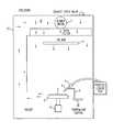
- FIG. 2shows a schematic diagram of a conventional CO 2 cryogenic cleaning system.
- the inventioncomprises the use of a reactive gas or the vapor of a reactive liquid which can diffuse into the high aspect ratio features or through a layer of contaminants film and chemically react with the foreign material. Cryogenic cleaning will also be used, either sequentially or simultaneously, with the reactive gas or vapor cleaning to remove the contaminants and films from the surfaces and from inside patterned features of semiconductors and other substrates requiring precision cleaning of their surfaces.
- the present inventioncomprises the use of a reactive gas or the vapor of a reactive liquid either simultaneously or sequentially with cryogenic cleaning.
- the reactive gas or vapor used in the process of the present inventionis selected according to its reactivity with the contaminants on the substrate surface. After reacting with these contaminants, it also preferably produces byproducts in a gaseous form.
- references to reactive gasmay include reactive vapors of a liquid and references to reactive vapors may include reactive gases.
- the reactive gas or vaporpreferably stays in contact with the substrate surface for up to 20 minutes, preferably less than 10 minutes, and more preferably less than 2 minutes.
- Examples of the vapor of a reactive liquid which may be used in the present processmay be the vapor of a high vapor pressure liquid and include, but not limited to, acetone, ethanol-acetone mixtures, isopropyl alcohol, methanol, methyl formate, methyl iodide, and ethyl bromide. It may also be another gas such as ozone, water vapor, hydrogen, nitrogen, nitrogen oxides, nitrogen trifluoride, helium, argon, neon, sulfur trioxide, oxygen, fluorine, or fluorocarbon gases or combinations of gases. The gas or vapor should be reactive with the organic photoresist as well as the fluoropolymer etch residue inside the features.
- reaction byproductsare preferably gaseous so that they can be removed from the cleaning chamber by the flow of nitrogen gas.
- gases and vaporsinclude isopropyl alcohol, ethanol-acetone mixtures, methanol, ozone, water vapor, nitrogen trifluoride, sulfur trioxide, oxygen, fluorine and fluorocarbon gases.
- cryogenic particlescannot get inside the high aspect ratio features of vias and trenches. Vapor is needed to diffuse into these features effectively. The vapor will then chemically react with the polymeric residue and convert it to gaseous by-products which can be removed from the surface by a flow of nitrogen across the substrate surface. Alternatively, the vapor can be introduced in a separate chamber kept under low pressure. The vapor phase reaction in this chamber could be done at temperatures of up to 200° C. Following the vapor clean, the wafers may be transferred to a second cleaning chamber at atmospheric pressure where the cryogenic cleaning can take place.
- the vapormay condense on the wafer surface.
- the condensationcould also lower the Hammaker constant and hence the force of adhesion of particles to surfaces. This condensation would thereby help in the particle removal by the CO 2 cryogenic cleaning.
- the foreign material to be removedincludes not only particle contaminants but also films of organic, inorganic, and metal-organic residues at various steps in microelectronic manufacturing both in FEOL (front-end-of-line) and BEOL processes. These films cannot be removed by purely physical mechanisms. Chemical assistance to any physical mechanism of removal is required to meet cleanliness requirements.
- the gas phase cleaningis the chemical means of cleaning whereas the cryogenic cleaning is predominantly the physical mechanism of cleaning. The two processes working in tandem or in sequence are able to completely remove the homogeneous or inhomogeneous foreign materials.
- the reactivity of the gas or vapor of a reactive liquid with the contaminantsmay be further increased using a free radical initiator such as ultra violet light, X-ray, Excimer laser, corona discharge or plasma to generate reactive chemical species. It is combined with the physical cleaning of snow or cryogenic aerosols to remove the non-reactive foreign material. Similar cleaning mechanisms are seen in wet cleaning and dual frequency plasma cleaning using downstream MW plasma to generate the chemical species for reaction with the contaminant and RF plasma to generate the ion bombardment.
- a free radical initiatorsuch as ultra violet light, X-ray, Excimer laser, corona discharge or plasma
- the vapor of a reactive liquidis sprayed through a nozzle attached to the same arm as a CO 2 cryogenic nozzle.
- the nozzlemay be a small stainless steel bore, 1 ⁇ 4 to 1 ⁇ 2′′ in diameter, or a specially designed nozzle with corona wire along the axis to initiate discharges in the vapor.
- the nozzleis preferably at an angle of approximately 10°-90° to the substrate surface.
- the vapormay also be sprayed through a showerhead positioned above the substrate surface to ensure uniform coverage of the substrate surface. During the vapor delivery, the substrate is preferably kept at the same temperature as the vapor.
- the substratemay be kept at a temperature below the vapor to initiate condensation of the vapor into a thin film of liquid on the substrate surface.
- the vapormay be made reactive with the assistance of a free radical initiator such as ultraviolet light, x-ray, excimer laser, corona discharge, or plasma. This step is generally included in the process when the vapor is not sufficiently reactive for a given contaminant type.
- the vaporis sprayed onto the substrate surface for preferably up to twenty minutes. It may be sprayed continuously or intermittently.
- a single type of vaporis used but a mixture of vapors may be used simultaneously or sequentially, if preferred, to remove particular foreign materials.
- the CO 2 cryogenic cleaningis performed.
- Cryogenic cleaningis well known within the industry and any well known technique may be used.
- a standard CO 2 cryogenic cleaning processis described in U.S. Pat. No. 5,853,962, which is incorporated by reference.
- FIG. 2As an example of a typical CO 2 cryogenic cleaning system, reference is made to the system 11 shown in FIG. 2 .
- This systemcomprises a cleaning container 12 in which system gases are circulated in the general direction indicated by the arrows in FIG. 2 .
- the cleaning container 12provides an ultra clean, enclosed or sealed cleaning zone. Ultra cleanliness of the cleaning zone may be achieved by virtue of means, such as a blower motor 7 , for passing system gases through an ultra purification filter, such as a ULPA filter 6 , as shown in FIG. 2.
- a wafer 1is held on a platen 2 by vacuum within the cleaning zone.
- the platen beneath the waferis kept at a controlled temperature of up to 100° C.
- Liquid CO 2from a cylinder at room temperature and 850 psi, is first passed through a sintered in-line filter 4 to filter out very small particles from the liquid stream to render the carbon dioxide as pure as possible and to reduce contaminants in the stream.
- the liquid CO 2is then made to expand through a small aperture nozzle 3 , preferably of from about 0.005′′ to 0.15′′ in diameter. The rapid expansion of the liquid causes the temperature to drop resulting in the formation of solid CO 2 snow particles entrained in a gaseous CO 2 stream flowing at a rate of approximately 1-3 cubic feet per minute.
- the stream of solid and gaseous CO 2is directed at the wafer surface at an angle of about 30° to about 60°, preferably at an angle of about 45°.
- the nozzleis preferably positioned at a distance of approximately 0.375′′ to 0.5′′ measured along the line of sight of the nozzle to the wafer surface.
- the platen 2moves back and forth on track 9 in the y direction while the arm 8 of the cleaning nozzle moves linearly on the track 10 in the x direction. This results in a rastered cleaning pattern on the wafer surface of which the step size and scan rate can be pre-set as desired.
- the humidity in the cleaning chamberis preferably maintained as low as possible, for example, ⁇ 40° C. dew point.
- the low humidityis present to prevent the condensation and freezing of water on the wafer surface from the atmosphere during the cleaning process which would increase the force of adhesion between the contaminant particles and the wafer surface by forming crystalline bridges between them.
- the low humiditycan be maintained by the flow of nitrogen or clean dry air.
- the systemalso has a polonium nozzle mounted directly behind the CO 2 nozzle for enhancing the charge neutralization of the wafer which is mounted on an electrically grounded platen.
- the electrostatic chargedevelops by triboelectrification due to the flow of CO 2 through the nozzle and across the wafer surface. It is aided by the low humidity maintained in the cleaning chamber.
- particulate contaminantssuch as particulate contaminants that are submicron in size, such as less than or equal to about 0.13 ⁇ m in size
- the removal mechanismis primarily by momentum transfer of the CO 2 cryogenic particles to overcome the force of adhesion of the contaminant particles on the wafer surface. Once the particles are “loosened”, the drag force of the gaseous CO 2 removes them from the surface of the wafer. It is also desirable to remove organic film contaminants from the wafer surface.
- the cleaning mechanism for organic film contaminantsis by the formation of a thin layer of liquid CO 2 at the interface of the organic contaminants and the surface due to the impact pressure of the cryogenic CO 2 on the wafer surface. The liquid CO 2 can then dissolve the organic contaminants and carry them away from the wafer surface.
- the spraying of the gas or vapor in accordance with the present inventionmay occur in the same chamber as the cryogenic cleaning or it may be done in a separate chamber.
- the cryogenic cleaningmay be initiated simultaneously with or directly after the reactive gas or vapor is used.
- the gas or vapor usedfor example water vapor, it may be desirable to purge the chamber of this vapor prior to initiating the cryogenic cleaning.
- This cleaning methodis particularly beneficial in removing homogeneous contaminants such as a film of post etch residue on the sidewalls of vias and trenches or the photoresist remaining after etching.
Landscapes
- Cleaning Or Drying Semiconductors (AREA)
Abstract
Description
where:
Cc=1+1.246(λ/a)+0.42(λ/a)exp[−0.87(a/λ)] (2)
where λ is the mean free path of gas molecules. Since the CO2cryogenic cleaning is conducted at atmospheric pressure, the Cunningham slip correction factor becomes equal to 1 in equation (1) for cryogenic particles larger than 0.1 μm in size.
Claims (22)
Priority Applications (7)
| Application Number | Priority Date | Filing Date | Title |
|---|---|---|---|
| US10/403,147US6949145B2 (en) | 2002-04-05 | 2003-03-31 | Vapor-assisted cryogenic cleaning |
| PCT/US2003/010354WO2003086668A1 (en) | 2002-04-05 | 2003-04-03 | Fluid assisted cryogenic cleaning |
| AU2003233485AAU2003233485A1 (en) | 2002-04-05 | 2003-04-03 | Fluid assisted cryogenic cleaning |
| EP03728337AEP1494821A4 (en) | 2002-04-05 | 2003-04-03 | Fluid assisted cryogenic cleaning |
| KR10-2004-7015867AKR20040098054A (en) | 2002-04-05 | 2003-04-03 | Fluid assisted cryogenic cleaning |
| JP2003583667AJP2005522056A (en) | 2002-04-05 | 2003-04-03 | Fluid assisted cryogenic cleaning |
| CN038103621ACN1665609A (en) | 2002-04-05 | 2003-04-03 | Fluid assisted cryogenic cleaning |
Applications Claiming Priority (2)
| Application Number | Priority Date | Filing Date | Title |
|---|---|---|---|
| US36985202P | 2002-04-05 | 2002-04-05 | |
| US10/403,147US6949145B2 (en) | 2002-04-05 | 2003-03-31 | Vapor-assisted cryogenic cleaning |
Publications (2)
| Publication Number | Publication Date |
|---|---|
| US20030188763A1 US20030188763A1 (en) | 2003-10-09 |
| US6949145B2true US6949145B2 (en) | 2005-09-27 |
Family
ID=28678292
Family Applications (1)
| Application Number | Title | Priority Date | Filing Date |
|---|---|---|---|
| US10/403,147Expired - LifetimeUS6949145B2 (en) | 2002-04-05 | 2003-03-31 | Vapor-assisted cryogenic cleaning |
Country Status (1)
| Country | Link |
|---|---|
| US (1) | US6949145B2 (en) |
Cited By (10)
| Publication number | Priority date | Publication date | Assignee | Title |
|---|---|---|---|---|
| US20040045578A1 (en)* | 2002-05-03 | 2004-03-11 | Jackson David P. | Method and apparatus for selective treatment of a precision substrate surface |
| US20040261814A1 (en)* | 2002-07-29 | 2004-12-30 | Mohamed Boumerzoug | Methods for resist stripping and cleaning surfaces substantially free of contaminants |
| US20050127037A1 (en)* | 2002-07-29 | 2005-06-16 | Tannous Adel G. | Methods for resist stripping and other processes for cleaning surfaces substantially free of contaminants |
| US20050215445A1 (en)* | 2002-07-29 | 2005-09-29 | Mohamed Boumerzoug | Methods for residue removal and corrosion prevention in a post-metal etch process |
| US20050263170A1 (en)* | 2002-07-29 | 2005-12-01 | Tannous Adel G | Methods for resist stripping and other processes for cleaning surfaces substantially free of contaminants |
| US20060040200A1 (en)* | 2004-08-20 | 2006-02-23 | Myung-Won Song | Method of fabricating organic light emitting display |
| US20060046182A1 (en)* | 2004-08-30 | 2006-03-02 | Myung-Won Song | Methods of fabricating organic light emitting display and donor substrate |
| US20090126760A1 (en)* | 2005-01-12 | 2009-05-21 | Boc, Inc. | System for cleaning a surface using crogenic aerosol and fluid reactant |
| US9919939B2 (en) | 2011-12-06 | 2018-03-20 | Delta Faucet Company | Ozone distribution in a faucet |
| US11458214B2 (en) | 2015-12-21 | 2022-10-04 | Delta Faucet Company | Fluid delivery system including a disinfectant device |
Families Citing this family (12)
| Publication number | Priority date | Publication date | Assignee | Title |
|---|---|---|---|---|
| US6852173B2 (en)* | 2002-04-05 | 2005-02-08 | Boc, Inc. | Liquid-assisted cryogenic cleaning |
| US6949145B2 (en) | 2002-04-05 | 2005-09-27 | Boc, Inc. | Vapor-assisted cryogenic cleaning |
| US7066789B2 (en)* | 2002-07-29 | 2006-06-27 | Manoclean Technologies, Inc. | Methods for resist stripping and other processes for cleaning surfaces substantially free of contaminants |
| US20040029494A1 (en)* | 2002-08-09 | 2004-02-12 | Souvik Banerjee | Post-CMP cleaning of semiconductor wafer surfaces using a combination of aqueous and CO2 based cryogenic cleaning techniques |
| US6953041B2 (en)* | 2002-10-09 | 2005-10-11 | Micell Technologies, Inc. | Compositions of transition metal species in dense phase carbon dioxide and methods of use thereof |
| MX2007007080A (en)* | 2004-12-13 | 2007-12-07 | Cool Clean Technologies Inc | Device for applying cryogenic composition and method of using same. |
| US20070181157A1 (en)* | 2006-02-07 | 2007-08-09 | Dadourian Daniel G | Apparatus and methods for flushing medical devices |
| US9099547B2 (en) | 2011-10-04 | 2015-08-04 | Infineon Technologies Ag | Testing process for semiconductor devices |
| US8883565B2 (en)* | 2011-10-04 | 2014-11-11 | Infineon Technologies Ag | Separation of semiconductor devices from a wafer carrier |
| US10625280B2 (en) | 2014-10-06 | 2020-04-21 | Tel Fsi, Inc. | Apparatus for spraying cryogenic fluids |
| KR102468565B1 (en) | 2014-10-06 | 2022-11-17 | 티이엘 매뉴팩처링 앤드 엔지니어링 오브 아메리카, 인크. | Systems and methods for treating substrates with cryogenic fluid mixtures |
| US10014191B2 (en) | 2014-10-06 | 2018-07-03 | Tel Fsi, Inc. | Systems and methods for treating substrates with cryogenic fluid mixtures |
Citations (17)
| Publication number | Priority date | Publication date | Assignee | Title |
|---|---|---|---|---|
| US4264641A (en) | 1977-03-17 | 1981-04-28 | Phrasor Technology Inc. | Electrohydrodynamic spraying to produce ultrafine particles |
| US5377705A (en) | 1993-09-16 | 1995-01-03 | Autoclave Engineers, Inc. | Precision cleaning system |
| US5775127A (en) | 1997-05-23 | 1998-07-07 | Zito; Richard R. | High dispersion carbon dioxide snow apparatus |
| US5796111A (en) | 1995-10-30 | 1998-08-18 | Phrasor Scientific, Inc. | Apparatus for cleaning contaminated surfaces using energetic cluster beams |
| US5853962A (en) | 1996-10-04 | 1998-12-29 | Eco-Snow Systems, Inc. | Photoresist and redeposition removal using carbon dioxide jet spray |
| US5908510A (en) | 1996-10-16 | 1999-06-01 | International Business Machines Corporation | Residue removal by supercritical fluids |
| US5928434A (en)* | 1998-07-13 | 1999-07-27 | Ford Motor Company | Method of mitigating electrostatic charge during cleaning of electronic circuit boards |
| US5931721A (en) | 1994-11-07 | 1999-08-03 | Sumitomo Heavy Industries, Ltd. | Aerosol surface processing |
| US5967156A (en)* | 1994-11-07 | 1999-10-19 | Krytek Corporation | Processing a surface |
| US6036581A (en) | 1997-05-26 | 2000-03-14 | Nec Corporation | Substrate cleaning method and apparatus |
| US6066032A (en) | 1997-05-02 | 2000-05-23 | Eco Snow Systems, Inc. | Wafer cleaning using a laser and carbon dioxide snow |
| US6231775B1 (en) | 1998-01-28 | 2001-05-15 | Anon, Inc. | Process for ashing organic materials from substrates |
| US6306564B1 (en) | 1997-05-27 | 2001-10-23 | Tokyo Electron Limited | Removal of resist or residue from semiconductors using supercritical carbon dioxide |
| US6332470B1 (en) | 1997-12-30 | 2001-12-25 | Boris Fishkin | Aerosol substrate cleaner |
| US6565920B1 (en)* | 2000-06-08 | 2003-05-20 | Honeywell International Inc. | Edge bead removal for spin-on materials containing low volatility solvents fusing carbon dioxide cleaning |
| US20030188763A1 (en) | 2002-04-05 | 2003-10-09 | Souvik Banerjee | Vapor-assisted cryogenic cleaning |
| US20040018803A1 (en) | 2002-07-29 | 2004-01-29 | Mohamed Boumerzoug | Methods for resist stripping and cleaning surfaces substantially free of contaminants |
Family Cites Families (2)
| Publication number | Priority date | Publication date | Assignee | Title |
|---|---|---|---|---|
| US188766A (en)* | 1877-03-27 | Improvement in insect-destroying compositions | ||
| JPS51107683A (en)* | 1975-03-18 | 1976-09-24 | Ngk Insulators Ltd | Taketsushotomeiaruminahatsukokan |
- 2003
- 2003-03-31USUS10/403,147patent/US6949145B2/ennot_activeExpired - Lifetime
Patent Citations (19)
| Publication number | Priority date | Publication date | Assignee | Title |
|---|---|---|---|---|
| US4264641A (en) | 1977-03-17 | 1981-04-28 | Phrasor Technology Inc. | Electrohydrodynamic spraying to produce ultrafine particles |
| US5377705A (en) | 1993-09-16 | 1995-01-03 | Autoclave Engineers, Inc. | Precision cleaning system |
| US6203406B1 (en) | 1994-11-07 | 2001-03-20 | Sumitomo Heavy Industries, Ltd. | Aerosol surface processing |
| US5931721A (en) | 1994-11-07 | 1999-08-03 | Sumitomo Heavy Industries, Ltd. | Aerosol surface processing |
| US5967156A (en)* | 1994-11-07 | 1999-10-19 | Krytek Corporation | Processing a surface |
| US6033484A (en) | 1995-10-30 | 2000-03-07 | Phrasor Scientific, Inc. | Method and apparatus for cleaning contaminated surfaces using energetic cluster beams |
| US5796111A (en) | 1995-10-30 | 1998-08-18 | Phrasor Scientific, Inc. | Apparatus for cleaning contaminated surfaces using energetic cluster beams |
| US5853962A (en) | 1996-10-04 | 1998-12-29 | Eco-Snow Systems, Inc. | Photoresist and redeposition removal using carbon dioxide jet spray |
| US5908510A (en) | 1996-10-16 | 1999-06-01 | International Business Machines Corporation | Residue removal by supercritical fluids |
| US6066032A (en) | 1997-05-02 | 2000-05-23 | Eco Snow Systems, Inc. | Wafer cleaning using a laser and carbon dioxide snow |
| US5775127A (en) | 1997-05-23 | 1998-07-07 | Zito; Richard R. | High dispersion carbon dioxide snow apparatus |
| US6036581A (en) | 1997-05-26 | 2000-03-14 | Nec Corporation | Substrate cleaning method and apparatus |
| US6306564B1 (en) | 1997-05-27 | 2001-10-23 | Tokyo Electron Limited | Removal of resist or residue from semiconductors using supercritical carbon dioxide |
| US6332470B1 (en) | 1997-12-30 | 2001-12-25 | Boris Fishkin | Aerosol substrate cleaner |
| US6231775B1 (en) | 1998-01-28 | 2001-05-15 | Anon, Inc. | Process for ashing organic materials from substrates |
| US5928434A (en)* | 1998-07-13 | 1999-07-27 | Ford Motor Company | Method of mitigating electrostatic charge during cleaning of electronic circuit boards |
| US6565920B1 (en)* | 2000-06-08 | 2003-05-20 | Honeywell International Inc. | Edge bead removal for spin-on materials containing low volatility solvents fusing carbon dioxide cleaning |
| US20030188763A1 (en) | 2002-04-05 | 2003-10-09 | Souvik Banerjee | Vapor-assisted cryogenic cleaning |
| US20040018803A1 (en) | 2002-07-29 | 2004-01-29 | Mohamed Boumerzoug | Methods for resist stripping and cleaning surfaces substantially free of contaminants |
Non-Patent Citations (4)
| Title |
|---|
| Edited by R.P. Donovan, Marcel Dekker Inc. "Particle Control for Semiconductor Manufacturing"-pp. 359, 361-364. |
| Edited by Werner Kern, Noyes Publications, 1993. "Handbook of Semiconductor Wafer Cleaning Technology Science, Technology, and Applications"-pp. 152, 181, 182. |
| Jointly written by: European Elect. Component Manufactures Assc., Japan Elect. & Information Tech. Industries Assc., Korea Semiconductor Industry Assc., Taiwan Semiconductor Industry Assc., International Technology Roadmap for Semiconductors 2001 Edition Executive Summary-pp. 12-16. |
| U.S. Appl. No. 10/324,221, filed Dec. 19, 2002, Banerjee et al. |
Cited By (19)
| Publication number | Priority date | Publication date | Assignee | Title |
|---|---|---|---|---|
| US20040045578A1 (en)* | 2002-05-03 | 2004-03-11 | Jackson David P. | Method and apparatus for selective treatment of a precision substrate surface |
| US20070246064A1 (en)* | 2002-05-03 | 2007-10-25 | Jackson David P | Method of treating a substrate |
| US7101260B2 (en) | 2002-07-29 | 2006-09-05 | Nanoclean Technologies, Inc. | Methods for resist stripping and other processes for cleaning surfaces substantially free of contaminants |
| US7297286B2 (en) | 2002-07-29 | 2007-11-20 | Nanoclean Technologies, Inc. | Methods for resist stripping and other processes for cleaning surfaces substantially free of contaminants |
| US20050263170A1 (en)* | 2002-07-29 | 2005-12-01 | Tannous Adel G | Methods for resist stripping and other processes for cleaning surfaces substantially free of contaminants |
| US20050215445A1 (en)* | 2002-07-29 | 2005-09-29 | Mohamed Boumerzoug | Methods for residue removal and corrosion prevention in a post-metal etch process |
| US20040261814A1 (en)* | 2002-07-29 | 2004-12-30 | Mohamed Boumerzoug | Methods for resist stripping and cleaning surfaces substantially free of contaminants |
| US7040961B2 (en) | 2002-07-29 | 2006-05-09 | Nanoclean Technologies, Inc. | Methods for resist stripping and cleaning surfaces substantially free of contaminants |
| US20050127037A1 (en)* | 2002-07-29 | 2005-06-16 | Tannous Adel G. | Methods for resist stripping and other processes for cleaning surfaces substantially free of contaminants |
| US7134941B2 (en) | 2002-07-29 | 2006-11-14 | Nanoclean Technologies, Inc. | Methods for residue removal and corrosion prevention in a post-metal etch process |
| US20060040200A1 (en)* | 2004-08-20 | 2006-02-23 | Myung-Won Song | Method of fabricating organic light emitting display |
| US7537878B2 (en)* | 2004-08-20 | 2009-05-26 | Samsung Sdi Co., Ltd. | Method of fabricating organic light emitting display |
| US20060046182A1 (en)* | 2004-08-30 | 2006-03-02 | Myung-Won Song | Methods of fabricating organic light emitting display and donor substrate |
| US7371502B2 (en)* | 2004-08-30 | 2008-05-13 | Samsung Sdi Co., Ltd. | Methods of fabricating organic light emitting display and donor substrate |
| US20090126760A1 (en)* | 2005-01-12 | 2009-05-21 | Boc, Inc. | System for cleaning a surface using crogenic aerosol and fluid reactant |
| US9919939B2 (en) | 2011-12-06 | 2018-03-20 | Delta Faucet Company | Ozone distribution in a faucet |
| US10947138B2 (en) | 2011-12-06 | 2021-03-16 | Delta Faucet Company | Ozone distribution in a faucet |
| US12162785B2 (en) | 2011-12-06 | 2024-12-10 | Delta Faucet Company | Ozone distribution in a faucet |
| US11458214B2 (en) | 2015-12-21 | 2022-10-04 | Delta Faucet Company | Fluid delivery system including a disinfectant device |
Also Published As
| Publication number | Publication date |
|---|---|
| US20030188763A1 (en) | 2003-10-09 |
Similar Documents
| Publication | Publication Date | Title |
|---|---|---|
| US6949145B2 (en) | Vapor-assisted cryogenic cleaning | |
| US6852173B2 (en) | Liquid-assisted cryogenic cleaning | |
| US10020217B2 (en) | Systems and methods for treating substrates with cryogenic fluid mixtures | |
| EP0288263B1 (en) | Apparatus and method for removing minute particles from a substrate | |
| US8197603B2 (en) | Method and apparatus for treating a substrate with dense fluid and plasma | |
| US10748789B2 (en) | Systems and methods for treating substrates with cryogenic fluid mixtures | |
| KR20010085939A (en) | Method of etching patterned layers useful as masking during subsequent etching or for damascene structures | |
| JPH08298252A (en) | Aerosol surface treatment | |
| US20040029494A1 (en) | Post-CMP cleaning of semiconductor wafer surfaces using a combination of aqueous and CO2 based cryogenic cleaning techniques | |
| US7134941B2 (en) | Methods for residue removal and corrosion prevention in a post-metal etch process | |
| EP1494821A1 (en) | Fluid assisted cryogenic cleaning | |
| US20050217706A1 (en) | Fluid assisted cryogenic cleaning | |
| US20100167552A1 (en) | Methods for particle removal during integrated circuit device fabrication | |
| TWI278927B (en) | Fluid assisted cryogenic cleaning | |
| Banerjee | Cryoaerosol cleaning of particles from surfaces | |
| US20060105683A1 (en) | Nozzle design for generating fluid streams useful in the manufacture of microelectronic devices | |
| McDermott et al. | Cleaning using argon/nitrogen cryogenic aerosols | |
| WO2018004678A1 (en) | Systems and methods for treating substrates with cryogenic fluid mixtures |
Legal Events
| Date | Code | Title | Description |
|---|---|---|---|
| AS | Assignment | Owner name:ECO-SNOW SYSTEMS, INC., CALIFORNIA Free format text:ASSIGNMENT OF ASSIGNORS INTEREST;ASSIGNORS:BANERJEE, SOUVIK;CHUNG, HARLAN FORREST;REEL/FRAME:013633/0463 Effective date:20020603 | |
| AS | Assignment | Owner name:BOC, INC., NEW JERSEY Free format text:ASSIGNMENT OF ASSIGNORS INTEREST;ASSIGNOR:ECO-SNOW SYSTEMS, INC.;REEL/FRAME:013797/0192 Effective date:20030708 | |
| STCF | Information on status: patent grant | Free format text:PATENTED CASE | |
| FPAY | Fee payment | Year of fee payment:4 | |
| AS | Assignment | Owner name:RAVE N.P., INC., FLORIDA Free format text:ASSIGNMENT OF ASSIGNORS INTEREST;ASSIGNOR:LINDE LLC;REEL/FRAME:024838/0193 Effective date:20100630 | |
| AS | Assignment | Owner name:COMVEST CAPITAL, LLC, FLORIDA Free format text:SECURITY AGREEMENT;ASSIGNOR:RAVE N.P., INC.;REEL/FRAME:025387/0886 Effective date:20101108 | |
| FPAY | Fee payment | Year of fee payment:8 | |
| AS | Assignment | Owner name:BRIDGE BANK, NATIONAL ASSOCIATION, CALIFORNIA Free format text:SECURITY AGREEMENT;ASSIGNOR:RAVE N.P., INC.;REEL/FRAME:030331/0646 Effective date:20110901 | |
| AS | Assignment | Owner name:AVIDBANK CORPORATE FINANCE, A DIVISION OF AVIDBANK Free format text:SECURITY AGREEMENT;ASSIGNOR:RAVE N.P., INC.;REEL/FRAME:031597/0548 Effective date:20131106 | |
| AS | Assignment | Owner name:RAVE N.P., INC., CALIFORNIA Free format text:RELEASE BY SECURED PARTY;ASSIGNOR:BRIDGE BANK, NATIONAL ASSOCIATION;REEL/FRAME:031616/0248 Effective date:20131113 | |
| AS | Assignment | Owner name:RAVE, LLC, FLORIDA Free format text:RELEASE BY SECURED PARTY;ASSIGNOR:COMVEST CAPITAL, LLC;REEL/FRAME:035664/0490 Effective date:20150427 | |
| FEPP | Fee payment procedure | Free format text:PAT HOLDER CLAIMS SMALL ENTITY STATUS, ENTITY STATUS SET TO SMALL (ORIGINAL EVENT CODE: LTOS); ENTITY STATUS OF PATENT OWNER: LARGE ENTITY | |
| FPAY | Fee payment | Year of fee payment:12 | |
| AS | Assignment | Owner name:RAVE N.P., INC., FLORIDA Free format text:RELEASE BY SECURED PARTY;ASSIGNOR:AVIDBANK SPECIALTY FINANCE, A DIVISION OF AVIDBANK;REEL/FRAME:048886/0669 Effective date:20190402 | |
| FEPP | Fee payment procedure | Free format text:ENTITY STATUS SET TO UNDISCOUNTED (ORIGINAL EVENT CODE: BIG.); ENTITY STATUS OF PATENT OWNER: LARGE ENTITY | |
| AS | Assignment | Owner name:BRUKER NANO, INC., FLORIDA Free format text:ASSIGNMENT OF ASSIGNORS INTEREST;ASSIGNORS:RAVE LLC;RAVE N.P., INC.;RAVE DIAMOND TECHNOLOGIES INC.;REEL/FRAME:050997/0604 Effective date:20190402 |