US6948924B2 - Mold assembly with modular mold shells - Google Patents
Mold assembly with modular mold shellsDownload PDFInfo
- Publication number
- US6948924B2 US6948924B2US10/411,339US41133903AUS6948924B2US 6948924 B2US6948924 B2US 6948924B2US 41133903 AUS41133903 AUS 41133903AUS 6948924 B2US6948924 B2US 6948924B2
- Authority
- US
- United States
- Prior art keywords
- mold
- sections
- body mold
- upper body
- mold sections
- Prior art date
- Legal status (The legal status is an assumption and is not a legal conclusion. Google has not performed a legal analysis and makes no representation as to the accuracy of the status listed.)
- Expired - Lifetime, expires
Links
- 239000000969carrierSubstances0.000claimsabstractdescription79
- 230000015572biosynthetic processEffects0.000claimsdescription10
- 239000007788liquidSubstances0.000claimsdescription3
- 238000007789sealingMethods0.000claims2
- 239000011810insulating materialSubstances0.000description4
- 238000000465mouldingMethods0.000description4
- 229920000139polyethylene terephthalatePolymers0.000description3
- 239000005020polyethylene terephthalateSubstances0.000description3
- 230000003139buffering effectEffects0.000description2
- 230000005484gravityEffects0.000description2
- 238000003780insertionMethods0.000description2
- 230000037431insertionEffects0.000description2
- NJPPVKZQTLUDBO-UHFFFAOYSA-NnovaluronChemical compoundC1=C(Cl)C(OC(F)(F)C(OC(F)(F)F)F)=CC=C1NC(=O)NC(=O)C1=C(F)C=CC=C1FNJPPVKZQTLUDBO-UHFFFAOYSA-N0.000description2
- 239000004033plasticSubstances0.000description2
- 229920003023plasticPolymers0.000description2
- -1polyethylene terephthalatePolymers0.000description2
- 230000000712assemblyEffects0.000description1
- 238000000429assemblyMethods0.000description1
- 235000013361beverageNutrition0.000description1
- 239000002131composite materialSubstances0.000description1
- 238000010276constructionMethods0.000description1
- 239000003599detergentSubstances0.000description1
- 238000005516engineering processMethods0.000description1
- 239000012530fluidSubstances0.000description1
- 239000000463materialSubstances0.000description1
- 235000014214soft drinkNutrition0.000description1
Images


Classifications
- B—PERFORMING OPERATIONS; TRANSPORTING
- B29—WORKING OF PLASTICS; WORKING OF SUBSTANCES IN A PLASTIC STATE IN GENERAL
- B29C—SHAPING OR JOINING OF PLASTICS; SHAPING OF MATERIAL IN A PLASTIC STATE, NOT OTHERWISE PROVIDED FOR; AFTER-TREATMENT OF THE SHAPED PRODUCTS, e.g. REPAIRING
- B29C49/00—Blow-moulding, i.e. blowing a preform or parison to a desired shape within a mould; Apparatus therefor
- B29C49/42—Component parts, details or accessories; Auxiliary operations
- B29C49/48—Moulds
- B29C49/4823—Moulds with incorporated heating or cooling means
- B—PERFORMING OPERATIONS; TRANSPORTING
- B29—WORKING OF PLASTICS; WORKING OF SUBSTANCES IN A PLASTIC STATE IN GENERAL
- B29C—SHAPING OR JOINING OF PLASTICS; SHAPING OF MATERIAL IN A PLASTIC STATE, NOT OTHERWISE PROVIDED FOR; AFTER-TREATMENT OF THE SHAPED PRODUCTS, e.g. REPAIRING
- B29C49/00—Blow-moulding, i.e. blowing a preform or parison to a desired shape within a mould; Apparatus therefor
- B29C49/42—Component parts, details or accessories; Auxiliary operations
- B29C49/62—Venting means
- B—PERFORMING OPERATIONS; TRANSPORTING
- B29—WORKING OF PLASTICS; WORKING OF SUBSTANCES IN A PLASTIC STATE IN GENERAL
- B29C—SHAPING OR JOINING OF PLASTICS; SHAPING OF MATERIAL IN A PLASTIC STATE, NOT OTHERWISE PROVIDED FOR; AFTER-TREATMENT OF THE SHAPED PRODUCTS, e.g. REPAIRING
- B29C49/00—Blow-moulding, i.e. blowing a preform or parison to a desired shape within a mould; Apparatus therefor
- B29C49/42—Component parts, details or accessories; Auxiliary operations
- B29C49/48—Moulds
- B29C49/4823—Moulds with incorporated heating or cooling means
- B29C2049/4825—Moulds with incorporated heating or cooling means for cooling moulds or mould parts
- B—PERFORMING OPERATIONS; TRANSPORTING
- B29—WORKING OF PLASTICS; WORKING OF SUBSTANCES IN A PLASTIC STATE IN GENERAL
- B29C—SHAPING OR JOINING OF PLASTICS; SHAPING OF MATERIAL IN A PLASTIC STATE, NOT OTHERWISE PROVIDED FOR; AFTER-TREATMENT OF THE SHAPED PRODUCTS, e.g. REPAIRING
- B29C49/00—Blow-moulding, i.e. blowing a preform or parison to a desired shape within a mould; Apparatus therefor
- B29C49/42—Component parts, details or accessories; Auxiliary operations
- B29C49/62—Venting means
- B29C2049/622—Venting means for venting air between preform and cavity, e.g. using venting holes, gaps or patterned moulds
- B—PERFORMING OPERATIONS; TRANSPORTING
- B29—WORKING OF PLASTICS; WORKING OF SUBSTANCES IN A PLASTIC STATE IN GENERAL
- B29C—SHAPING OR JOINING OF PLASTICS; SHAPING OF MATERIAL IN A PLASTIC STATE, NOT OTHERWISE PROVIDED FOR; AFTER-TREATMENT OF THE SHAPED PRODUCTS, e.g. REPAIRING
- B29C2949/00—Indexing scheme relating to blow-moulding
- B29C2949/07—Preforms or parisons characterised by their configuration
- B29C2949/0715—Preforms or parisons characterised by their configuration the preform having one end closed
- B—PERFORMING OPERATIONS; TRANSPORTING
- B29—WORKING OF PLASTICS; WORKING OF SUBSTANCES IN A PLASTIC STATE IN GENERAL
- B29C—SHAPING OR JOINING OF PLASTICS; SHAPING OF MATERIAL IN A PLASTIC STATE, NOT OTHERWISE PROVIDED FOR; AFTER-TREATMENT OF THE SHAPED PRODUCTS, e.g. REPAIRING
- B29C49/00—Blow-moulding, i.e. blowing a preform or parison to a desired shape within a mould; Apparatus therefor
- B29C49/02—Combined blow-moulding and manufacture of the preform or the parison
- B29C49/06—Injection blow-moulding
- B—PERFORMING OPERATIONS; TRANSPORTING
- B29—WORKING OF PLASTICS; WORKING OF SUBSTANCES IN A PLASTIC STATE IN GENERAL
- B29C—SHAPING OR JOINING OF PLASTICS; SHAPING OF MATERIAL IN A PLASTIC STATE, NOT OTHERWISE PROVIDED FOR; AFTER-TREATMENT OF THE SHAPED PRODUCTS, e.g. REPAIRING
- B29C49/00—Blow-moulding, i.e. blowing a preform or parison to a desired shape within a mould; Apparatus therefor
- B29C49/42—Component parts, details or accessories; Auxiliary operations
- B29C49/4273—Auxiliary operations after the blow-moulding operation not otherwise provided for
- B29C49/4283—Deforming the finished article
- B29C49/42832—Moving or inverting sections, e.g. inverting bottom as vacuum panel
Definitions
- the vertical registryis achieved by the upper body mold sections having outer walls with a continuous groove cut therein that extends axially around these outer walls and inner walls of the carriers each having a flange half ring interconnecting member extending in therefrom that is adapted to fit into the continuous groove of the outer walls of the upper body mold sections.
- FIG. 3is a partially exploded view of a portion of an alternative embodiment of the mold assembly illustrating one lower shim lower body mold section;
- the position C of the mold carriers 20is maintained in a fixed position relative to the molding machine (not shown). Further due to the vertical registry between the upper mold sections 42 and the mold carriers 20 provided by the carrier interconnecting or flange member 102 , location A of the carriers 20 remains fixed vertically relative to location B of the top cavity inserts 40 . Hence, the location of the top cavity inserts 40 at location B is fixed vertically relative to the mold machine so as to provide for the proper insertion of the tubular portion 27 of the preform 30 into cavity 42 and the proper positioning of the preform neck 26 at it's flange 26 a against the seating surface 45 of the modular mold shells 22 .
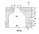
- FIGS. 2 to 5another feature of the mold half shells 22 is shown by the use of two different patterns of grooves 80 in FIGS. 2 , 3 , 4 and 180 in FIG. 5 .
- These patterns of grooves 80 , 180are machined into the outer surface of both the main mold section 54 and the upper body mold section 46 .
- the pattern of grooves 80provide a series of longitudinally spaced apart slotted apertures providing axially extending recessed open air spaces 87 .
- the mold half carriers 20are adapted to surround the mold half shells 22 with the inner walls 56 of the mold half carriers 20 contacting the outer wall surface portions 86 of the mold half shells 22 . This forms a series of longitudinally spaced apart open air pockets 87 extending axially around the mold half shells 22 to create thermal buffering pockets 87 that reduce thermal conduction from the mold face through the shells 22 and out through the mold carriers 20 .
- a pattern of intersecting groovesis shown at 180 .
- This patternshows the grooves extending orthogonally to each other however the pattern is shown to simply represent that more than one form of pattern of grooves may be applied that either run in parallel to each other or intersect with each other, for example.
Landscapes
- Engineering & Computer Science (AREA)
- Manufacturing & Machinery (AREA)
- Mechanical Engineering (AREA)
- Moulds For Moulding Plastics Or The Like (AREA)
Abstract
Description
Claims (20)
Priority Applications (2)
| Application Number | Priority Date | Filing Date | Title |
|---|---|---|---|
| CA2425970ACA2425970C (en) | 2003-04-11 | 2003-04-11 | Mold assembly with modular mold shells |
| US10/411,339US6948924B2 (en) | 2003-04-11 | 2003-04-11 | Mold assembly with modular mold shells |
Applications Claiming Priority (2)
| Application Number | Priority Date | Filing Date | Title |
|---|---|---|---|
| CA2425970ACA2425970C (en) | 2003-04-11 | 2003-04-11 | Mold assembly with modular mold shells |
| US10/411,339US6948924B2 (en) | 2003-04-11 | 2003-04-11 | Mold assembly with modular mold shells |
Publications (2)
| Publication Number | Publication Date |
|---|---|
| US20040202746A1 US20040202746A1 (en) | 2004-10-14 |
| US6948924B2true US6948924B2 (en) | 2005-09-27 |
Family
ID=33512092
Family Applications (1)
| Application Number | Title | Priority Date | Filing Date |
|---|---|---|---|
| US10/411,339Expired - LifetimeUS6948924B2 (en) | 2003-04-11 | 2003-04-11 | Mold assembly with modular mold shells |
Country Status (2)
| Country | Link |
|---|---|
| US (1) | US6948924B2 (en) |
| CA (1) | CA2425970C (en) |
Cited By (21)
| Publication number | Priority date | Publication date | Assignee | Title |
|---|---|---|---|---|
| US20060233909A1 (en)* | 2005-04-18 | 2006-10-19 | Graham Packaging Company, L.P. | Quick change mold |
| US20070042070A1 (en)* | 2005-07-28 | 2007-02-22 | Mark Hallink | Shell Attachment Means For Blow Molding Machines |
| US20070212442A1 (en)* | 2003-11-04 | 2007-09-13 | Nonogaki Osmar K | Blow Mode Shell With Volume Insert System For A Blowing Machine |
| US20080003321A1 (en)* | 2006-01-20 | 2008-01-03 | Kerr George S | Modular mold system for production of product families |
| US20080020085A1 (en)* | 2006-07-21 | 2008-01-24 | Sidel Participations | Moulding device for the manufacture of thermoplastic containers |
| US20080181982A1 (en)* | 2007-01-31 | 2008-07-31 | Lane Michael T | Blow mold design |
| US20080206390A1 (en)* | 2007-02-27 | 2008-08-28 | Krones Ag | Blow mold |
| US20090232929A1 (en)* | 2008-02-04 | 2009-09-17 | Erik Blochmann | Mould Housing |
| US20090263535A1 (en)* | 2008-04-21 | 2009-10-22 | Sidel Participations | Device for moulding containers comprising means of adjusting the volume dimensions of the moulding cavity |
| US20090273118A1 (en)* | 2008-04-30 | 2009-11-05 | Krones Ag | Method for transferring preforms to a blow molding machine and mold carrier for at least one preform |
| US20100104681A1 (en)* | 2006-07-21 | 2010-04-29 | Sidel Participations | Blow-mold assembly for the manufacturing of containers, including a mold and a plug for fluid connection |
| US20110129558A1 (en)* | 2008-06-27 | 2011-06-02 | Sidel Participations | Mould end-wall support for a blow-moulding machine, and blow-moulding machine comprising said end-wall support |
| US20110165285A1 (en)* | 2007-01-31 | 2011-07-07 | Lane Michael T | Blow mold design |
| US8070470B2 (en) | 2009-02-06 | 2011-12-06 | Wentworth Mold Ltd. | Mold assembly |
| US20120148703A1 (en)* | 2009-09-07 | 2012-06-14 | Sidel Participations | Molding device provided with a controlled means for clampingly attaching a half-mold by means of slidable attachment bolts |
| US20120288582A1 (en)* | 2011-05-11 | 2012-11-15 | Ipar Mold S.A. De C.V. | Mold assembly with interchangeable insert for blow-molding |
| US11225107B1 (en) | 2020-09-09 | 2022-01-18 | Mahindra N.A. Tech Center | Axle carrier housing with reinforcement structure |
| US11535057B2 (en) | 2020-09-09 | 2022-12-27 | Mahindra N.A. Tech Center | Axle assembly with sealed wheel end bearings and sealed pinion input bearings |
| US11565838B2 (en)* | 2018-10-17 | 2023-01-31 | Krones Ag | Mould filling with subsequent closing under internal pressure |
| US11648745B2 (en) | 2020-09-09 | 2023-05-16 | Mahindra N.A. Tech Center | Modular tooling for axle housing and manufacturing process |
| US11655891B2 (en) | 2020-09-09 | 2023-05-23 | Mahindra N.A. Tech Center | Method of machining an axle carrier housing |
Families Citing this family (10)
| Publication number | Priority date | Publication date | Assignee | Title |
|---|---|---|---|---|
| FR2924974B1 (en)* | 2007-12-17 | 2012-12-28 | Sidel Participations | MOLD FOR MANUFACTURING THERMOPLASTIC CONTAINERS AND BLOW-MOLDING OR BLOW-STRETCHING EQUIPMENT EQUIPPED WITH SUCH A MOLD |
| CN105730825B (en) | 2010-10-01 | 2019-08-16 | 福林德施普产品有限公司 | The modularization of laterally attached feature with raising interlocks container |
| US9290300B2 (en) | 2012-02-21 | 2016-03-22 | Friendship Products Llc | Modular interlocking containers |
| MX361593B (en)* | 2012-06-05 | 2018-12-10 | Sa Des Eaux Minerales Devian | Blow moulded bottle, method of manufacturing and mould. |
| DE102013109716A1 (en)* | 2013-09-05 | 2015-03-05 | Krones Ag | Blow mold, blow molding machine and process for forming plastic preforms into plastic containers with air discharge |
| FR3015344B1 (en) | 2013-12-19 | 2016-05-27 | Sidel Participations | MOLD ELEMENT FOR FORMING CONTAINER HAVING DECOMPRESSION EVENTS IN THE FORM OF SLOTS |
| CN110509527B (en)* | 2019-09-05 | 2021-12-10 | 武义利泽维工贸有限公司 | Blow molding plastic forming die |
| US20250010536A1 (en)* | 2021-11-03 | 2025-01-09 | Amcor Rigid Packaging Usa, Llc | Tooling assembly for forming a container by blow molding |
| DE102022121447A1 (en)* | 2022-08-24 | 2024-02-29 | Krones Aktiengesellschaft | Aseptic blow mold with rear exhaust channels and method for forming containers under aseptic conditions |
| CN116100753B (en)* | 2023-02-13 | 2023-08-22 | 广州市旭胜模具有限公司 | Adjustable automobile shell injection mold |
Citations (25)
| Publication number | Priority date | Publication date | Assignee | Title |
|---|---|---|---|---|
| US170464A (en)* | 1875-11-30 | Improvement in molds for glassware | ||
| US3380121A (en) | 1965-07-30 | 1968-04-30 | American Can Co | Mold with replaceable inserts |
| US3861640A (en) | 1973-05-21 | 1975-01-21 | Ideal Toy Corp | Interchangeable mold assembly |
| US3978910A (en) | 1975-07-07 | 1976-09-07 | Gladwin Floyd R | Mold plate cooling system |
| US4032278A (en) | 1976-03-02 | 1977-06-28 | Forest Mechanical Products Corporation | Sealing and shearing member in a plastic resin blow molding machine |
| US4151976A (en) | 1977-11-07 | 1979-05-01 | The Plastic Forming Company, Inc. | Modular die set for blow molding containers |
| USRE30215E (en) | 1976-03-02 | 1980-02-19 | Forest Mechanical Products Corp. | Sealing and shearing member in a plastic resin blow molding machine |
| US4330248A (en) | 1980-09-15 | 1982-05-18 | Platte Richard L | Mold with adjustable inserts |
| US4699585A (en)* | 1984-09-28 | 1987-10-13 | Kautex-Werke Reinold Hagen Ag | Blow molding apparatus |
| JPS63202425A (en) | 1987-02-18 | 1988-08-22 | Toyo Seikan Kaisha Ltd | Manufacture of biaxially stretched polyester bottle |
| US4815960A (en) | 1985-05-06 | 1989-03-28 | Martin Rudolph | Blowing mould adjustable in longitudinal direction |
| US4822543A (en)* | 1985-07-30 | 1989-04-18 | Yoshino Kogyosho Co., Ltd. | Method for forming plastic containers |
| US4863046A (en) | 1987-12-24 | 1989-09-05 | Continental Pet Technologies, Inc. | Hot fill container |
| US4884961A (en)* | 1985-07-30 | 1989-12-05 | Yoshino Kogyosho Co., Ltd. | Apparatus for forming plastic containers |
| US4927680A (en) | 1987-12-24 | 1990-05-22 | Continental Pet Technologies, Inc. | Preform and method of forming container therefrom |
| GB2240300A (en) | 1990-01-24 | 1991-07-31 | Metal Box Plc | Blow mould having cooling channels |
| CA2082350A1 (en) | 1991-11-15 | 1993-05-16 | Wayne N. Collette | Modular mold |
| US5217729A (en)* | 1990-03-22 | 1993-06-08 | Toppan Printing Co., Ltd. | Mold for plastic bottles |
| US5571474A (en) | 1991-09-14 | 1996-11-05 | Mauser-Werke Gmbh | Blow moulding machine |
| US5766299A (en)* | 1996-11-04 | 1998-06-16 | Miller; Ronald P. | Mold for shaping glass |
| US5968560A (en) | 1995-04-19 | 1999-10-19 | Sidel | Blow molding device for producing thermoplastic containers |
| US6113377A (en) | 1995-08-22 | 2000-09-05 | Continental Pet Technologies, Inc. | Mould replacement and method of mould replacement in a blow moulding apparatus |
| CA2313881A1 (en)* | 2000-07-14 | 2002-01-14 | Wentworth Mould Inc. | Universal blow mold assembly |
| US6444159B2 (en) | 1999-05-04 | 2002-09-03 | Sidel, Inc. | Blow mold shell and shell assembly |
| US6447281B1 (en) | 1998-09-11 | 2002-09-10 | Sidel, Inc. | Blow mold shell and shell holder assembly for blow-molding machine |
- 2003
- 2003-04-11USUS10/411,339patent/US6948924B2/ennot_activeExpired - Lifetime
- 2003-04-11CACA2425970Apatent/CA2425970C/ennot_activeExpired - Lifetime
Patent Citations (28)
| Publication number | Priority date | Publication date | Assignee | Title |
|---|---|---|---|---|
| US170464A (en)* | 1875-11-30 | Improvement in molds for glassware | ||
| US3380121A (en) | 1965-07-30 | 1968-04-30 | American Can Co | Mold with replaceable inserts |
| US3861640A (en) | 1973-05-21 | 1975-01-21 | Ideal Toy Corp | Interchangeable mold assembly |
| US3978910A (en) | 1975-07-07 | 1976-09-07 | Gladwin Floyd R | Mold plate cooling system |
| USRE30215E (en) | 1976-03-02 | 1980-02-19 | Forest Mechanical Products Corp. | Sealing and shearing member in a plastic resin blow molding machine |
| US4032278A (en) | 1976-03-02 | 1977-06-28 | Forest Mechanical Products Corporation | Sealing and shearing member in a plastic resin blow molding machine |
| US4151976A (en) | 1977-11-07 | 1979-05-01 | The Plastic Forming Company, Inc. | Modular die set for blow molding containers |
| US4330248A (en) | 1980-09-15 | 1982-05-18 | Platte Richard L | Mold with adjustable inserts |
| US4699585A (en)* | 1984-09-28 | 1987-10-13 | Kautex-Werke Reinold Hagen Ag | Blow molding apparatus |
| US4815960A (en) | 1985-05-06 | 1989-03-28 | Martin Rudolph | Blowing mould adjustable in longitudinal direction |
| US4884961A (en)* | 1985-07-30 | 1989-12-05 | Yoshino Kogyosho Co., Ltd. | Apparatus for forming plastic containers |
| US4822543A (en)* | 1985-07-30 | 1989-04-18 | Yoshino Kogyosho Co., Ltd. | Method for forming plastic containers |
| JPS63202425A (en) | 1987-02-18 | 1988-08-22 | Toyo Seikan Kaisha Ltd | Manufacture of biaxially stretched polyester bottle |
| US4927680A (en) | 1987-12-24 | 1990-05-22 | Continental Pet Technologies, Inc. | Preform and method of forming container therefrom |
| US4863046A (en) | 1987-12-24 | 1989-09-05 | Continental Pet Technologies, Inc. | Hot fill container |
| GB2240300A (en) | 1990-01-24 | 1991-07-31 | Metal Box Plc | Blow mould having cooling channels |
| US5217729A (en)* | 1990-03-22 | 1993-06-08 | Toppan Printing Co., Ltd. | Mold for plastic bottles |
| US5571474A (en) | 1991-09-14 | 1996-11-05 | Mauser-Werke Gmbh | Blow moulding machine |
| US5255889A (en) | 1991-11-15 | 1993-10-26 | Continental Pet Technologies, Inc. | Modular wold |
| US5411699A (en) | 1991-11-15 | 1995-05-02 | Continental Pet Technologies, Inc. | Modular mold |
| CA2082350A1 (en) | 1991-11-15 | 1993-05-16 | Wayne N. Collette | Modular mold |
| US5968560A (en) | 1995-04-19 | 1999-10-19 | Sidel | Blow molding device for producing thermoplastic containers |
| US6113377A (en) | 1995-08-22 | 2000-09-05 | Continental Pet Technologies, Inc. | Mould replacement and method of mould replacement in a blow moulding apparatus |
| US5766299A (en)* | 1996-11-04 | 1998-06-16 | Miller; Ronald P. | Mold for shaping glass |
| US6447281B1 (en) | 1998-09-11 | 2002-09-10 | Sidel, Inc. | Blow mold shell and shell holder assembly for blow-molding machine |
| US6444159B2 (en) | 1999-05-04 | 2002-09-03 | Sidel, Inc. | Blow mold shell and shell assembly |
| CA2313881A1 (en)* | 2000-07-14 | 2002-01-14 | Wentworth Mould Inc. | Universal blow mold assembly |
| US6428302B1 (en) | 2000-07-14 | 2002-08-06 | Wentworth Mold Inc. | Universal blow mold assembly |
Cited By (32)
| Publication number | Priority date | Publication date | Assignee | Title |
|---|---|---|---|---|
| US20070212442A1 (en)* | 2003-11-04 | 2007-09-13 | Nonogaki Osmar K | Blow Mode Shell With Volume Insert System For A Blowing Machine |
| US7335007B2 (en)* | 2005-04-18 | 2008-02-26 | Graham Packaging Company, L.P. | Quick change mold |
| US20060233909A1 (en)* | 2005-04-18 | 2006-10-19 | Graham Packaging Company, L.P. | Quick change mold |
| US20070042070A1 (en)* | 2005-07-28 | 2007-02-22 | Mark Hallink | Shell Attachment Means For Blow Molding Machines |
| US20080003321A1 (en)* | 2006-01-20 | 2008-01-03 | Kerr George S | Modular mold system for production of product families |
| US20100104681A1 (en)* | 2006-07-21 | 2010-04-29 | Sidel Participations | Blow-mold assembly for the manufacturing of containers, including a mold and a plug for fluid connection |
| US20080020085A1 (en)* | 2006-07-21 | 2008-01-24 | Sidel Participations | Moulding device for the manufacture of thermoplastic containers |
| US8348658B2 (en)* | 2006-07-21 | 2013-01-08 | Sidel Participations | Blow-mold assembly for the manufacturing of containers, including a mold and a plug for fluid connection |
| US7753670B2 (en)* | 2006-07-21 | 2010-07-13 | Sidel Participations | Moulding device for the manufacture of thermoplastic containers |
| US8454343B2 (en) | 2007-01-31 | 2013-06-04 | Amcor Limited | Blow mold design |
| US7887315B2 (en)* | 2007-01-31 | 2011-02-15 | Amcor Limited | Blow mold design |
| US20110165285A1 (en)* | 2007-01-31 | 2011-07-07 | Lane Michael T | Blow mold design |
| US20080181982A1 (en)* | 2007-01-31 | 2008-07-31 | Lane Michael T | Blow mold design |
| US20080206390A1 (en)* | 2007-02-27 | 2008-08-28 | Krones Ag | Blow mold |
| US7905719B2 (en)* | 2007-02-27 | 2011-03-15 | Krones Ag | Blow mold |
| US20090232929A1 (en)* | 2008-02-04 | 2009-09-17 | Erik Blochmann | Mould Housing |
| US8105071B2 (en)* | 2008-02-04 | 2012-01-31 | Krones Ag | Mould housing |
| US20090263535A1 (en)* | 2008-04-21 | 2009-10-22 | Sidel Participations | Device for moulding containers comprising means of adjusting the volume dimensions of the moulding cavity |
| US8043084B2 (en)* | 2008-04-21 | 2011-10-25 | Sidel Participations | Device for moulding containers comprising means of adjusting the volume dimensions of the moulding cavity |
| US20090273118A1 (en)* | 2008-04-30 | 2009-11-05 | Krones Ag | Method for transferring preforms to a blow molding machine and mold carrier for at least one preform |
| US8118587B2 (en)* | 2008-04-30 | 2012-02-21 | Krones Ag | Method for transferring preforms to a blow molding machine and mold carrier for at least one preform |
| US20110129558A1 (en)* | 2008-06-27 | 2011-06-02 | Sidel Participations | Mould end-wall support for a blow-moulding machine, and blow-moulding machine comprising said end-wall support |
| US8070470B2 (en) | 2009-02-06 | 2011-12-06 | Wentworth Mold Ltd. | Mold assembly |
| US20120148703A1 (en)* | 2009-09-07 | 2012-06-14 | Sidel Participations | Molding device provided with a controlled means for clampingly attaching a half-mold by means of slidable attachment bolts |
| US8770961B2 (en)* | 2009-09-07 | 2014-07-08 | Sidel Participations | Molding device provided with a controlled means for clampingly attaching a half-mold by means of slidable attachment bolts |
| US20120288582A1 (en)* | 2011-05-11 | 2012-11-15 | Ipar Mold S.A. De C.V. | Mold assembly with interchangeable insert for blow-molding |
| US8573960B2 (en)* | 2011-05-11 | 2013-11-05 | Ipar Mold S.A. De C.V. | Mold assembly with interchangeable insert for blow-molding |
| US11565838B2 (en)* | 2018-10-17 | 2023-01-31 | Krones Ag | Mould filling with subsequent closing under internal pressure |
| US11225107B1 (en) | 2020-09-09 | 2022-01-18 | Mahindra N.A. Tech Center | Axle carrier housing with reinforcement structure |
| US11535057B2 (en) | 2020-09-09 | 2022-12-27 | Mahindra N.A. Tech Center | Axle assembly with sealed wheel end bearings and sealed pinion input bearings |
| US11648745B2 (en) | 2020-09-09 | 2023-05-16 | Mahindra N.A. Tech Center | Modular tooling for axle housing and manufacturing process |
| US11655891B2 (en) | 2020-09-09 | 2023-05-23 | Mahindra N.A. Tech Center | Method of machining an axle carrier housing |
Also Published As
| Publication number | Publication date |
|---|---|
| CA2425970A1 (en) | 2004-10-11 |
| CA2425970C (en) | 2010-06-01 |
| US20040202746A1 (en) | 2004-10-14 |
Similar Documents
| Publication | Publication Date | Title |
|---|---|---|
| US6948924B2 (en) | Mold assembly with modular mold shells | |
| US6913455B2 (en) | Hot fill mold shell assembly with reduced heat transfer | |
| US8070470B2 (en) | Mold assembly | |
| US5255889A (en) | Modular wold | |
| US6444159B2 (en) | Blow mold shell and shell assembly | |
| US6428302B1 (en) | Universal blow mold assembly | |
| JP2007277083A (en) | Mold cooling system for i. s. machine | |
| JP2018012329A (en) | Molding unit for container equipped with fluid circuit and pneumatic circuit appearing at top face | |
| GB2240300A (en) | Blow mould having cooling channels | |
| US7727455B2 (en) | Apparatus and method for creation of a blow molded container having holes therein | |
| BRPI0515683B1 (en) | method to manufacture a plastic bottle | |
| US7338272B2 (en) | Apparatus for blow molding | |
| US20110129558A1 (en) | Mould end-wall support for a blow-moulding machine, and blow-moulding machine comprising said end-wall support | |
| ES2083089T3 (en) | APPARATUS AND PROCEDURE FOR COOLING A MOLD. | |
| US8226402B2 (en) | Mold for fabricating thermoplastic containers, and a blow-molding or stretch-blow molding installation equipped with such a mold | |
| CN110625910A (en) | Molded unit with movable impingement insert ventilated by fluid circuit from impingement fluid circuit | |
| US5795598A (en) | Assembly for inflating a parison and forming the neck of a plastic bottle | |
| US5629032A (en) | Blow-molding apparatus | |
| KR20040066123A (en) | Installation for blow moulding thermoplastic polymer containers | |
| JP2018020554A (en) | Container molding unit equipped with boxing insert with air circulation | |
| US20040241275A1 (en) | Hollow nickel mold members for use in blow molding | |
| JP7234213B2 (en) | Blow molding mold and blow molding equipment | |
| US7748973B2 (en) | Mold with an insert for a container blow molding machine | |
| US20090155400A1 (en) | Apparatus for Blow Molding | |
| JP4405059B2 (en) | Deadplate Assembly for I.S. Machine Sections |
Legal Events
| Date | Code | Title | Description |
|---|---|---|---|
| AS | Assignment | Owner name:WENTWORTH MOLD INC., CANADA Free format text:ASSIGNMENT OF ASSIGNORS INTEREST;ASSIGNORS:TSAU, TAR;NITSCHE, REINHOLD ERNST;KYI, KYI SAN;REEL/FRAME:013959/0276 Effective date:20030409 | |
| STCF | Information on status: patent grant | Free format text:PATENTED CASE | |
| AS | Assignment | Owner name:1589711 ONTARIO INC., CANADA Free format text:MERGER;ASSIGNOR:WENTWORTH MOULD INC.;REEL/FRAME:017776/0368 Effective date:20031001 Owner name:WENTWORTH MOLD, LTD., CANADA Free format text:ASSIGNMENT OF ASSIGNORS INTEREST;ASSIGNOR:1589711 ONTARIO INC.;REEL/FRAME:017776/0364 Effective date:20060530 | |
| AS | Assignment | Owner name:GENERAL ELECTRIC CAPITAL CORPORATION, ILLINOIS Free format text:SECURITY INTEREST;ASSIGNOR:WENTWORTH MOLD LTD.;REEL/FRAME:017882/0001 Effective date:20060228 | |
| AS | Assignment | Owner name:NORTHCASTLE LOAN LP, AS AGENT, ONTARIO Free format text:PATENT SECURITY AGREEMENT;ASSIGNORS:AMHIL ENTERPRISES;AMHIL ENTERPRISES LTD.;IZON INDUSTRIES LTD;AND OTHERS;REEL/FRAME:018463/0161 Effective date:20060228 | |
| AS | Assignment | Owner name:FORTRESS CREDIT CORP LIMITED, AS AGENT, IRELAND Free format text:SECURED PARTY ASSIGNMENT (CONVEYANCE & ASSIGNMENT DOCUMENTS);ASSIGNOR:NORTHCASTLE LOAN LP, AS AGENT;REEL/FRAME:018711/0763 Effective date:20061025 | |
| FPAY | Fee payment | Year of fee payment:4 | |
| FPAY | Fee payment | Year of fee payment:8 | |
| FPAY | Fee payment | Year of fee payment:12 |