US6948665B2 - Fuel injector including an orifice disc, and a method of forming the orifice disc with an asymmetrical punch - Google Patents
Fuel injector including an orifice disc, and a method of forming the orifice disc with an asymmetrical punchDownload PDFInfo
- Publication number
- US6948665B2 US6948665B2US10/608,389US60838903AUS6948665B2US 6948665 B2US6948665 B2US 6948665B2US 60838903 AUS60838903 AUS 60838903AUS 6948665 B2US6948665 B2US 6948665B2
- Authority
- US
- United States
- Prior art keywords
- orifice
- wall
- generally
- metering
- axis
- Prior art date
- Legal status (The legal status is an assumption and is not a legal conclusion. Google has not performed a legal analysis and makes no representation as to the accuracy of the status listed.)
- Expired - Lifetime, expires
Links
- 239000000446fuelSubstances0.000titleclaimsabstractdescription64
- 238000000034methodMethods0.000titleclaimsdescription19
- 230000000149penetrating effectEffects0.000claimsabstractdescription12
- 239000007921spraySubstances0.000claimsdescription9
- 230000008685targetingEffects0.000claimsdescription4
- 238000005553drillingMethods0.000claimsdescription2
- 238000004080punchingMethods0.000claimsdescription2
- 230000008878couplingEffects0.000claims13
- 238000010168coupling processMethods0.000claims13
- 238000005859coupling reactionMethods0.000claims13
- 230000001788irregularEffects0.000claims2
- 238000007789sealingMethods0.000description4
- 238000002347injectionMethods0.000description3
- 239000007924injectionSubstances0.000description3
- 239000000463materialSubstances0.000description3
- 238000002485combustion reactionMethods0.000description2
- 238000004519manufacturing processMethods0.000description2
- 230000008569processEffects0.000description2
- 238000007493shaping processMethods0.000description2
- 238000003466weldingMethods0.000description2
- 230000004075alterationEffects0.000description1
- 238000005452bendingMethods0.000description1
- 230000001143conditioned effectEffects0.000description1
- 238000010276constructionMethods0.000description1
- 230000001186cumulative effectEffects0.000description1
- 230000006870functionEffects0.000description1
- 230000001939inductive effectEffects0.000description1
- 239000007788liquidSubstances0.000description1
- 238000003754machiningMethods0.000description1
- 230000004048modificationEffects0.000description1
- 238000012986modificationMethods0.000description1
- 230000002093peripheral effectEffects0.000description1
- 238000005498polishingMethods0.000description1
- 230000000717retained effectEffects0.000description1
- 238000011064split stream procedureMethods0.000description1
- 230000007704transitionEffects0.000description1
- 238000011144upstream manufacturingMethods0.000description1
- 238000009736wettingMethods0.000description1
Images


Classifications
- F—MECHANICAL ENGINEERING; LIGHTING; HEATING; WEAPONS; BLASTING
- F02—COMBUSTION ENGINES; HOT-GAS OR COMBUSTION-PRODUCT ENGINE PLANTS
- F02M—SUPPLYING COMBUSTION ENGINES IN GENERAL WITH COMBUSTIBLE MIXTURES OR CONSTITUENTS THEREOF
- F02M61/00—Fuel-injectors not provided for in groups F02M39/00 - F02M57/00 or F02M67/00
- F02M61/16—Details not provided for in, or of interest apart from, the apparatus of groups F02M61/02 - F02M61/14
- F02M61/18—Injection nozzles, e.g. having valve seats; Details of valve member seated ends, not otherwise provided for
- F02M61/1853—Orifice plates
- F—MECHANICAL ENGINEERING; LIGHTING; HEATING; WEAPONS; BLASTING
- F02—COMBUSTION ENGINES; HOT-GAS OR COMBUSTION-PRODUCT ENGINE PLANTS
- F02M—SUPPLYING COMBUSTION ENGINES IN GENERAL WITH COMBUSTIBLE MIXTURES OR CONSTITUENTS THEREOF
- F02M51/00—Fuel-injection apparatus characterised by being operated electrically
- F02M51/06—Injectors peculiar thereto with means directly operating the valve needle
- F02M51/061—Injectors peculiar thereto with means directly operating the valve needle using electromagnetic operating means
- F02M51/0625—Injectors peculiar thereto with means directly operating the valve needle using electromagnetic operating means characterised by arrangement of mobile armatures
- F02M51/0664—Injectors peculiar thereto with means directly operating the valve needle using electromagnetic operating means characterised by arrangement of mobile armatures having a cylindrically or partly cylindrically shaped armature, e.g. entering the winding; having a plate-shaped or undulated armature entering the winding
- F02M51/0671—Injectors peculiar thereto with means directly operating the valve needle using electromagnetic operating means characterised by arrangement of mobile armatures having a cylindrically or partly cylindrically shaped armature, e.g. entering the winding; having a plate-shaped or undulated armature entering the winding the armature having an elongated valve body attached thereto
- F—MECHANICAL ENGINEERING; LIGHTING; HEATING; WEAPONS; BLASTING
- F02—COMBUSTION ENGINES; HOT-GAS OR COMBUSTION-PRODUCT ENGINE PLANTS
- F02M—SUPPLYING COMBUSTION ENGINES IN GENERAL WITH COMBUSTIBLE MIXTURES OR CONSTITUENTS THEREOF
- F02M61/00—Fuel-injectors not provided for in groups F02M39/00 - F02M57/00 or F02M67/00
- F02M61/16—Details not provided for in, or of interest apart from, the apparatus of groups F02M61/02 - F02M61/14
- F02M61/168—Assembling; Disassembling; Manufacturing; Adjusting
- F—MECHANICAL ENGINEERING; LIGHTING; HEATING; WEAPONS; BLASTING
- F02—COMBUSTION ENGINES; HOT-GAS OR COMBUSTION-PRODUCT ENGINE PLANTS
- F02M—SUPPLYING COMBUSTION ENGINES IN GENERAL WITH COMBUSTIBLE MIXTURES OR CONSTITUENTS THEREOF
- F02M61/00—Fuel-injectors not provided for in groups F02M39/00 - F02M57/00 or F02M67/00
- F02M61/16—Details not provided for in, or of interest apart from, the apparatus of groups F02M61/02 - F02M61/14
- F02M61/18—Injection nozzles, e.g. having valve seats; Details of valve member seated ends, not otherwise provided for
- F02M61/1806—Injection nozzles, e.g. having valve seats; Details of valve member seated ends, not otherwise provided for characterised by the arrangement of discharge orifices, e.g. orientation or size
- F02M61/1833—Discharge orifices having changing cross sections, e.g. being divergent
Definitions
- This inventionrelates generally to electrically operated fuel injectors of the type that inject volatile liquid fuel into an automotive vehicle internal combustion engine, and in particular the invention relates to a novel thin disc orifice member for such a fuel injector.
- sac volumeis defined as a volume downstream of a needle/seat sealing perimeter and upstream of the orifice hole(s).
- the practical limit of dimpling a geometric shaped into an orifice disc pre-conditioned with straight orifice holesis the depth or altitude of the geometric shape required to obtain the desired spray angle(s). Obtaining the larger bend and split spray angles makes the manufacture more difficult and increases sac volume at the same time.
- the depth of the geometryincreases, the amount of individual hole and dimple distortion also increases. In extreme instances, the disc material may shear between holes or at creases in the geometrical dimple.
- the present inventionprovides a fuel injector for spray targeting fuel.
- the fuel injectorincludes a seat, a movable member cooperating with the seat, and an orifice plate.
- the seatincludes a passage that extends along a longitudinal axis, and the movable member cooperates with the seat to permit and prevent a flow of fuel through the passage.
- the metering orifice discincludes a member having first and second generally parallel surfaces, and an orifice penetrating the member. The first surface generally confronts the seat, and the second surface faces opposite the first surface.
- the orificeis defined by a wall that couples the first and second surfaces. And the wall includes first and second portions. The first portion is spaced from the first surface and extends substantially perpendicular to the first and second generally planar surfaces. The second portion couples the first portion to the first surface and extends at a first oblique angle that varies with respect to the first surface.
- the present inventionalso provides a metering orifice disc for a fuel injector.
- the fuel injectorincludes a passage that extends between an inlet and an outlet, a seat that is proximate the outlet, and a closure member that cooperates with the seat to permit and prevent a flow of fuel through the passage.
- the metering orifice discincludes a member and an orifice penetrating the member.
- the memberincludes first and second generally parallel surfaces. The first surface is adapted to generally confront the valve seat, and the second surface faces opposite the first surface.
- the orificeis defined by a wall that couples the first and second surfaces.
- the wallincludes a first portion that is spaced from the first surface and a second portion that couples the first portion to the first surface.
- the first portion of the wallextends substantially perpendicular to the first and second generally planar surfaces. And the second portion of the wall extends at a first oblique angle with respect to the first surface.
- the first oblique angle vanesso as to define an asymmetrical chamfer.
- the present inventionalso provides a method of forming a metering orifice disc for a fuel injector.
- the metering orifice discincludes a member that has first and second generally parallel surfaces.
- the methodincludes forming an orifice penetrating the member and deforming the orifice proximate the first surface.
- the orificeis defined by a wall that couples the first and second surfaces, and the orifice extends along an orifice axis that is generally perpendicular to the first and second generally parallel surfaces.
- the deformingincludes forming an asymmetrical chamfer with respect to the orifice axis.
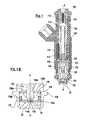
- FIG. 1Ais a cross-sectional view of a fuel injector according to a preferred embodiment of the present invention.
- FIG. 1Bis a close-up cross-sectional view of the outlet end portion of the fuel injector of FIG. 1 A.
- FIGS. 2A and 2Bdepict part of the process of forming the metering orifice disc of the preferred embodiments.
- FIG. 2Cdepicts details of the metering orifice disc of FIG. 2B in a fragmentary cross-sectional view.
- FIG. 2Ddepicts details of the metering orifice disc of FIG. 2B in a fragmentary perspective view.
- FIGS. 3A , 3 B, and 3 Cdepict yet another process of forming the metering orifice disc of the preferred embodiments.
- FIGS. 1-3illustrate the preferred embodiments.
- a fuel injector 100extends along a longitudinal axis A—A, as illustrated in FIG. 1A , and includes: a fuel inlet tube 110 , an adjustment tube 112 , a filter assembly 114 , a coil assembly 118 , a coil spring 116 , an armature 120 , a closure member assembly 122 , a non-magnetic shell 124 , a fuel injector overmold 134 , a body 128 , a body shell 130 , a body shell overmold 132 , a coil assembly housing 126 , a guide member 136 for the closure member assembly 122 , a seat 138 , and a metering disc 140 .
- the construction of fuel injector 100can be of a type similar to those disclosed in commonly assigned U.S. Pat. Nos. 4,854,024; 5,174,505; and 6,520,421.
- FIG. 1Bshows the nozzle end of a body 128 of a solenoid operated fuel injector 100 having a metering orifice disc 140 embodying principles of the invention.
- the nozzle end of fuel injector 100is also like those of the aforementioned patents including that of a stack.
- the stackincludes a guide member 136 and a seat 138 , which are disposed axially interiorly of metering orifice disc 140 .
- the stackcan be retained by a suitable technique such as, for example, a retaining lip with a retainer or by welding the disc 140 to the seat 138 and welding the seat 138 to the body 128 .
- Seat 138can include a frustoconical seating surface 138 a that leads from guide member 136 to a central passage 138 b of the seat 138 that, in turn, leads to a central portion 140 b of metering orifice disc 140 .
- Guide member 136includes a central guide opening 136 a for guiding the axial reciprocation of a sealing end 122 a of a closure member assembly 122 and several through-openings 136 b distributed around opening 136 a to provide for fuel to flow through sealing end 122 a to the space around seat 138 .
- FIG. 1Bshows the hemispherical sealing end 122 a of closure member assembly 122 seated on seat 138 , thus preventing fuel flow through the fuel injector.
- the metering orifice disc 140can have a generally circular shape with a circular outer peripheral portion 140 a that circumferentially bounds the central portion 140 b that is located axially in the fuel injector.
- the central portion 140 b of metering orifice disc 140is imperforate except for the presence of one or more asymmetrical orifices 32 via which fuel passes through metering orifice disc 140 .
- Any number of asymmetrical orifices 32can be configured in a suitable array about the longitudinal axis A—A so that the metering orifice disc 140 can be used for its intended purpose in metering, atomizing, and targeting fuel spray of a fuel injector.
- the preferred embodimentsinclude four such through-asymmetrical orifices 32 (although only two are shown in the Figures) arranged about the longitudinal axis A—A through the metering orifice disc 140 .
- the preferred embodiments of the metering orifice disc 140can be formed as follows. Initially, a generally planar blank work piece 10 having a first surface 20 spaced at a distance from a second surface 40 without any orifices extending therethrough is provided. The blank 10 is penetrated by a suitable technique such as, for example, punching, coining, drilling or laser machining to form a pilot through opening or pilot orifice 30 that is symmetrical about and extending along an axis Y-Y of the tool 42 generally perpendicular to the planar surfaces 20 and 40 of the blank.
- a suitable techniquesuch as, for example, punching, coining, drilling or laser machining to form a pilot through opening or pilot orifice 30 that is symmetrical about and extending along an axis Y-Y of the tool 42 generally perpendicular to the planar surfaces 20 and 40 of the blank.
- the symmetrical pilot through-opening 30is formed by a cylindrical punch 42 that forms a perpendicular burnished wall section 30 a between surface 20 and proximate surface 40 with a rough chamfer 30 b formed by a breakout (i.e., a fracturing) of material by the punch tool 42 as the punch tool 42 penetrates through to the second surface 40 .
- a breakouti.e., a fracturing
- the symmetrical through opening or orifice 30is further penetrated by a suitable technique to form an asymmetrical through opening or orifice 32 .
- the work piececan be processed into a metering orifice disc 140 by a suitable material finishing technique such as, for example, stamping the work piece into a desired configuration, grinding, deburring, skiving, or polishing.
- the asymmetrical orifice 32is formed by a punch tool 50 having an apex 52 with at least two leading edges disposed about the tool axis Y—Y such that the resulting cross-section of the punch tool 50 is asymmetric about the orifice axis 200 ( FIGS. 2C , 2 D).
- Each of the at least two leading edgescan include a first leading edge 54 and a second leading edge 56 .
- the first leading edge 54is oriented at a first lead angle ⁇ ° different from the second lead angle ⁇ ° of the second leading edge 56 .
- the first lead angle ⁇ °is approximately 25 degrees and the second lead angle ⁇ ° is approximately 30 degrees.
- the asymmetrical orifice 32can be formed of a suitable cross-sectional area such as for example, square, rectangular, oval or circular, the preferred embodiments include generally circular orifices having a diameter of about 100 microns, and more particularly, about 125 microns.
- the first and second surfaces 20 , 40 of the metering orifice disc 140are spaced apart over a distance of between 100 to 300 microns or greater.
- the asymmetrical orifice 32can include a first entry chamfer 32 a disposed at a first angular extension ⁇ ° about the longitudinal axis 200 ( FIGS. 2C and 2D ) and merging into a second entry chamfer 32 b disposed at a second angular extension (D) ( FIGS. 2C and 2D ) through a transition area due to the generated surface of the tool 50 .
- the first entry chamfer 32 acan be oriented at approximately the first lead angle ⁇ °.
- the second entry chamfer 32 bcan be oriented at approximately the second lead angle ⁇ ° such that the first and second entry chamfers 32 a and 32 b are asymmetrical about the tool axis Y—Y ( FIG.
- first and second entry chamferswith respect to the surface 20 can form a first perimeter 33 a having a geometric center 33 b oblique relative to the longitudinal axis (FIGS. 2 D and 2 C).
- the perimeter 33 ais a generally elliptical perimeter.
- the first entry chamfer 32 aleads to a first wall surface 32 c (FIG. 2 C).
- the first wall surface 32 cis disposed at about the first angular extension ⁇ ° about the longitudinal axis 200 and merges into a second wall surface 32 d disposed at the second angular extension ⁇ ° ( FIG. 2D ) such that the first and second wall surfaces 32 c and 32 d are symmetric to axis 200 .
- the first wall surface 32 c and the second wall surface 32 dare parallel to the tool axis Y—Y, which in this case is coincident with the orifice axis 200 such that both surfaces form a cylindrical wall surface about the axis 200 .
- the entry chamfers 32 a and 32 bform an asymmetric conical surface about the axis 200 .
- the junctures between first and second chamfers 32 a , 32 b with first and second wall surfaces 32 c , 32 dform a second perimeter 33 c ( FIG. 2D ) disposed generally oblique to the first and second surfaces 20 , 40 .
- the first wall surface 32 ccan merge into a first exit chamfer 32 e .
- the second wall surface 32 dcan merge into a second exit chamfer 32 f .
- the junctures of the first and second exit chamfers 32 e and 32 f with respect to the surface 20can form a third perimeter having a geometric center coincident to or offset with respect to the axis 200 .
- the perimeter of the first and second exit chamfers 32 e and 32 fare symmetric to the axis 200 .
- the orifice 32Due to the asymmetrical geometry of the orifice 32 , fuel 34 flowing through the orifice 32 of the metering disc 140 tends to flow through at an orifice angle ⁇ generally oblique to the longitudinal axis: Thus, even though the orifice 32 is formed by two tools moving in a perpendicular direction with respect to the first or second surfaces 20 or 40 , the orifice formed is an asymmetrical orifice 32 rather than a symmetrical orifice.
- the asymmetrical orifice 32essentially emulates an angled orifice (as referenced to the longitudinal axis 200 ) by inducing the fuel flow 34 to flow at the orifice angle approximating the angle ⁇ .
- the orifice angle ⁇can be increased for each of the asymmetrical orifices 32 by dimpling or deforming a region on which the asymmetrical orifice 32 is located.
- an increased orifice angle 0 of fuel flow 34can be formed by initially forming the asymmetrical orifice 32 as discussed earlier in a generally flat blank work piece 12 having first surface 22 and second surface 42 (FIG. 3 A). Thereafter, the disc blank 12 is dimpled to form at least one planar facet at a dimpling angle ⁇ (FIG. 3 B).
- the new orifice angle ⁇is a cumulative effect and resultant of the angle ⁇ and the angle ⁇ and is related as a function of: (1) the original orifice angle ⁇ of fuel flow formed by the asymmetrical orifice geometry and (2) the dimpling angle ⁇ of the dimpled disc blank 12 .
- the new bending angle ⁇results from approximately the sum of the orifice angle ⁇ and the dimpling angle ⁇ .
- the preferred embodiments of the disc blank 12can be formed by a method as follows.
- the methodincludes forming a first asymmetrical orifice 32 penetrating the first and second surfaces 22 , 42 (FIG. 3 A), respectively, and also includes forming a first facet 44 on which the first orifice 32 is disposed thereon such that the first facet 44 extends generally parallel to a first plane 125 oblique to the base plane 150 (FIG. 3 B).
- the first facet 44can be formed by a suitable technique such as, for example, stamping or drawing such that the first surface 22 becomes a generally concave surface and the second surface 42 becomes a generally convex surface.
- a plurality of asymmetrical orifices 32 and so oncan be formed at the same time or within a short interval of time with the forming of the first asymmetrical orifice 32 .
- a second facet 46can be formed at the same time or within a short interval of time with the first facet 44 .
- the second facet 46can be generally parallel to a second plane 127 oblique to the base plane 150 such that the orifice 32 is oblique to the orifice axis 200 .
- the second facet 46can also be oblique with respect to the first facet 44 .
- the blank 12is finished by a suitable finishing technique and installed in a body 128 (FIG. 3 C).
- the benefits of the asymmetrical geometry of the orifice 32are believed to be many.
- the orifice 32can be formed by two tools moving in a direction perpendicular to the work piece to generate an orifice that emulates an angled orifice without requiring a tool to be oriented oblique to the perpendicular direction.
- the asymmetrical geometry of the orifice 32tends to prevent the fuel flow 34 from attaching to the walls of the orifice 32 , which feature is believed to permit more of the fuel to be atomized.
- the entry and exit chamfers of the orificecan be formed so that fuel flowing through the orifice can be induced to form a spiral, which may be desirable in certain configurations of the air intake manifold and engine.
Landscapes
- Engineering & Computer Science (AREA)
- Chemical & Material Sciences (AREA)
- Combustion & Propulsion (AREA)
- Mechanical Engineering (AREA)
- General Engineering & Computer Science (AREA)
- Manufacturing & Machinery (AREA)
- Physics & Mathematics (AREA)
- Electromagnetism (AREA)
- Fuel-Injection Apparatus (AREA)
Abstract
Description
Claims (19)
Priority Applications (4)
| Application Number | Priority Date | Filing Date | Title |
|---|---|---|---|
| US10/608,389US6948665B2 (en) | 2003-06-30 | 2003-06-30 | Fuel injector including an orifice disc, and a method of forming the orifice disc with an asymmetrical punch |
| DE112004000897.2TDE112004000897B4 (en) | 2003-06-30 | 2004-06-21 | Fuel injection valve with a nozzle disk and method for producing the nozzle disk with an asymmetric mandrel |
| JP2006517467AJP4435161B2 (en) | 2003-06-30 | 2004-06-21 | Orifice disk for fuel injector and method of forming the same |
| PCT/US2004/019703WO2005005818A1 (en) | 2003-06-30 | 2004-06-21 | A fuel injector including an orifice disc, and a method of forming the orifice disc with an asymmetrical punch |
Applications Claiming Priority (1)
| Application Number | Priority Date | Filing Date | Title |
|---|---|---|---|
| US10/608,389US6948665B2 (en) | 2003-06-30 | 2003-06-30 | Fuel injector including an orifice disc, and a method of forming the orifice disc with an asymmetrical punch |
Publications (2)
| Publication Number | Publication Date |
|---|---|
| US20040262430A1 US20040262430A1 (en) | 2004-12-30 |
| US6948665B2true US6948665B2 (en) | 2005-09-27 |
Family
ID=33540572
Family Applications (1)
| Application Number | Title | Priority Date | Filing Date |
|---|---|---|---|
| US10/608,389Expired - LifetimeUS6948665B2 (en) | 2003-06-30 | 2003-06-30 | Fuel injector including an orifice disc, and a method of forming the orifice disc with an asymmetrical punch |
Country Status (4)
| Country | Link |
|---|---|
| US (1) | US6948665B2 (en) |
| JP (1) | JP4435161B2 (en) |
| DE (1) | DE112004000897B4 (en) |
| WO (1) | WO2005005818A1 (en) |
Cited By (7)
| Publication number | Priority date | Publication date | Assignee | Title |
|---|---|---|---|---|
| US20050017098A1 (en)* | 2003-07-21 | 2005-01-27 | Joseph J. Michael | Fuel injector including an orifice disc, and a method of forming the orifice disc including punching and shaving |
| US20050241446A1 (en)* | 2004-04-28 | 2005-11-03 | Siemens Vdo Automotive, Incorporated | Asymmetrical punch |
| US20060060680A1 (en)* | 2004-08-05 | 2006-03-23 | Michael Dallmeyer | Fuel injector with a deep-drawn thin shell connector member and method of connecting components |
| US20070145163A1 (en)* | 2005-12-21 | 2007-06-28 | Manubolu Avinash R | Fuel injector nozzle with tip alignment apparatus |
| US20080203069A1 (en)* | 2007-02-28 | 2008-08-28 | Chen-Chun Kao | EDM process for manufacturing reverse tapered holes |
| US20090007411A1 (en)* | 2002-12-27 | 2009-01-08 | Denso Corporation | Method for manufacturing injection hole member |
| US20180003131A1 (en)* | 2015-01-31 | 2018-01-04 | L'orange Gmbh | Fuel injector for operation with combustible gas |
Families Citing this family (12)
| Publication number | Priority date | Publication date | Assignee | Title |
|---|---|---|---|---|
| US20060226264A1 (en)* | 2005-04-08 | 2006-10-12 | Bacho Paul S V Iii | Fuel injector director plate having chamfered passages and method for making such a plate |
| DE102005032378A1 (en)* | 2005-07-08 | 2007-01-11 | Siemens Ag | Magnetic navigable endoscopy capsule with sensor for detecting a physiological size |
| JP2008008168A (en)* | 2006-06-28 | 2008-01-17 | Denso Corp | Method for manufacturing nozzle hole plate |
| DE102008044096A1 (en)* | 2008-11-27 | 2010-06-02 | Robert Bosch Gmbh | Method for producing throttle bores with a low caviation transfer point |
| JP5959892B2 (en) | 2012-03-26 | 2016-08-02 | 日立オートモティブシステムズ株式会社 | Spark ignition type fuel injection valve |
| JP2015523501A (en)* | 2012-08-01 | 2015-08-13 | スリーエム イノベイティブ プロパティズ カンパニー | Directing fuel discharge by directing the flow out of the nozzle off-axis |
| CN104736836B (en) | 2012-08-01 | 2019-01-11 | 3M创新有限公司 | Fuel injector with improved fuel draining coefficient |
| KR101337713B1 (en)* | 2012-12-20 | 2013-12-06 | 주식회사 현대케피코 | Vehicular gdi injector with valve seat body for fuel atomization |
| JP6339628B2 (en)* | 2016-06-22 | 2018-06-06 | 日立オートモティブシステムズ株式会社 | Fuel injection valve |
| DE102016211688A1 (en)* | 2016-06-29 | 2018-01-04 | Robert Bosch Gmbh | Injector for injecting a fluid with a tapering inflow region of a passage opening |
| JP6630262B2 (en)* | 2016-11-18 | 2020-01-15 | 本田技研工業株式会社 | Injector |
| US11253875B2 (en) | 2018-07-27 | 2022-02-22 | Vitesco Technologies USA, LLC | Multi-dimple orifice disc for a fluid injector, and methods for constructing and utilizing same |
Citations (29)
| Publication number | Priority date | Publication date | Assignee | Title |
|---|---|---|---|---|
| US335334A (en) | 1886-02-02 | Method of making dies | ||
| US600687A (en) | 1898-03-15 | Holes in brush backs by pressure | ||
| US2737831A (en) | 1950-06-02 | 1956-03-13 | American Viscose Corp | Process for making a spinneret |
| US2846902A (en) | 1956-02-06 | 1958-08-12 | American Saw & Tool Company | Drill elements |
| JPS5232192A (en) | 1975-09-06 | 1977-03-11 | Yamamoto Seisakusho:Kk | Through hole boring method for flat heat screw |
| US4072039A (en) | 1976-04-30 | 1978-02-07 | Yoshitaka Nakanishi | Method for forming counter-sunk hole in a base material and an apparatus for carrying out the same |
| JPS59223121A (en) | 1983-06-01 | 1984-12-14 | Miyagi Seiki Kk | Die set |
| JPS60137529A (en) | 1983-12-27 | 1985-07-22 | Amada Metoretsukusu:Kk | Method for forming countersink of platelike member |
| US4923169A (en) | 1987-12-23 | 1990-05-08 | Siemens-Bendix Automotive Electronics L.P. | Multi-stream thin edge orifice disks for valves |
| US4970926A (en) | 1987-09-17 | 1990-11-20 | Neurodynamics, Inc. | Apparatus for making angled hole ventricular catheter |
| US5002231A (en) | 1988-12-07 | 1991-03-26 | Robert Bosch Gmbh | Injection valve |
| US5201806A (en) | 1991-06-17 | 1993-04-13 | Siemens Automotive L.P. | Tilted fuel injector having a thin disc orifice member |
| US5335864A (en) | 1991-07-17 | 1994-08-09 | Robert Bosch Gmbh | Fuel-injection valve |
| US5344081A (en) | 1992-04-01 | 1994-09-06 | Siemens Automotive L.P. | Injector valve seat with recirculation trap |
| US5350119A (en)* | 1993-06-01 | 1994-09-27 | Siemens Automotive L.P. | Clad metal orifice disk for fuel injectors |
| US5365819A (en) | 1992-12-22 | 1994-11-22 | Prompac Industries, Inc. | Method and process for manufacturing expandable packing material |
| US5553397A (en) | 1993-03-03 | 1996-09-10 | Koenig & Bauer Aktiengesellschaft | Device for drying printed sheets or web in printing presses |
| US5636796A (en) | 1994-03-03 | 1997-06-10 | Nippondenso Co., Ltd. | Fluid injection nozzle |
| US5697154A (en) | 1994-02-16 | 1997-12-16 | Nippondenso Co., Ltd. | Method of producing a fluid injection valve |
| US5730368A (en) | 1994-09-30 | 1998-03-24 | Robert Bosch Gmbh | Nozzle plate, particularly for injection valves and processes for manufacturing a nozzle plate |
| US5746376A (en) | 1994-12-20 | 1998-05-05 | Robert Bosch Gmbh | Valve and method for the production of a valve |
| US5816093A (en) | 1994-09-29 | 1998-10-06 | Nitto Kohki Co., Ltd. | Method and tool for forming a tapered hole in a cylindrical work by punching extruding |
| JPH11117830A (en) | 1997-10-20 | 1999-04-27 | Hitachi Ltd | Injector |
| US5931391A (en) | 1996-10-25 | 1999-08-03 | Denso Corporation | Fluid injection valve |
| US6009787A (en) | 1994-09-07 | 2000-01-04 | Haenggi; Eugen | Process and device for punching holes in flat workpieces |
| US6039271A (en) | 1996-08-01 | 2000-03-21 | Robert Bosch Gmbh | Fuel injection valve |
| US6089476A (en) | 1997-06-25 | 2000-07-18 | Toyota Jidosha Kabushiki Kaisha | Fuel injection valve for an internal combustion engine |
| US6131826A (en) | 1996-12-21 | 2000-10-17 | Robert Bosch Gmbh | Valve with combined valve seat body and perforated injection disk |
| JP2003120473A (en) | 2001-10-18 | 2003-04-23 | Hitachi Ltd | Manufacturing method of nozzle or orifice plate of liquid injection valve, nozzle or orifice plate of liquid injection valve, and fuel injection valve |
Family Cites Families (3)
| Publication number | Priority date | Publication date | Assignee | Title |
|---|---|---|---|---|
| DE19639506A1 (en)* | 1996-09-26 | 1998-04-02 | Bosch Gmbh Robert | Perforated disc and valve with a perforated disc |
| JP3814815B2 (en)* | 1998-03-25 | 2006-08-30 | 株式会社デンソー | Injection hole plate and manufacturing method thereof |
| JP3629698B2 (en)* | 2000-10-03 | 2005-03-16 | 株式会社デンソー | Fluid injection nozzle injection hole processing apparatus and fluid injection nozzle injection hole processing method |
- 2003
- 2003-06-30USUS10/608,389patent/US6948665B2/ennot_activeExpired - Lifetime
- 2004
- 2004-06-21JPJP2006517467Apatent/JP4435161B2/ennot_activeExpired - Fee Related
- 2004-06-21WOPCT/US2004/019703patent/WO2005005818A1/enactiveApplication Filing
- 2004-06-21DEDE112004000897.2Tpatent/DE112004000897B4/ennot_activeExpired - Fee Related
Patent Citations (31)
| Publication number | Priority date | Publication date | Assignee | Title |
|---|---|---|---|---|
| US600687A (en) | 1898-03-15 | Holes in brush backs by pressure | ||
| US335334A (en) | 1886-02-02 | Method of making dies | ||
| US2737831A (en) | 1950-06-02 | 1956-03-13 | American Viscose Corp | Process for making a spinneret |
| US2846902A (en) | 1956-02-06 | 1958-08-12 | American Saw & Tool Company | Drill elements |
| JPS5232192A (en) | 1975-09-06 | 1977-03-11 | Yamamoto Seisakusho:Kk | Through hole boring method for flat heat screw |
| US4072039A (en) | 1976-04-30 | 1978-02-07 | Yoshitaka Nakanishi | Method for forming counter-sunk hole in a base material and an apparatus for carrying out the same |
| JPS59223121A (en) | 1983-06-01 | 1984-12-14 | Miyagi Seiki Kk | Die set |
| JPS60137529A (en) | 1983-12-27 | 1985-07-22 | Amada Metoretsukusu:Kk | Method for forming countersink of platelike member |
| US4970926A (en) | 1987-09-17 | 1990-11-20 | Neurodynamics, Inc. | Apparatus for making angled hole ventricular catheter |
| US4923169A (en) | 1987-12-23 | 1990-05-08 | Siemens-Bendix Automotive Electronics L.P. | Multi-stream thin edge orifice disks for valves |
| US5002231A (en) | 1988-12-07 | 1991-03-26 | Robert Bosch Gmbh | Injection valve |
| US5201806A (en) | 1991-06-17 | 1993-04-13 | Siemens Automotive L.P. | Tilted fuel injector having a thin disc orifice member |
| US5335864A (en) | 1991-07-17 | 1994-08-09 | Robert Bosch Gmbh | Fuel-injection valve |
| US5344081A (en) | 1992-04-01 | 1994-09-06 | Siemens Automotive L.P. | Injector valve seat with recirculation trap |
| US5365819B1 (en) | 1992-12-22 | 1997-04-22 | Prompac Ind Inc | Method and process for manufacturing expandable packing material |
| US5365819A (en) | 1992-12-22 | 1994-11-22 | Prompac Industries, Inc. | Method and process for manufacturing expandable packing material |
| US5553397A (en) | 1993-03-03 | 1996-09-10 | Koenig & Bauer Aktiengesellschaft | Device for drying printed sheets or web in printing presses |
| US5350119A (en)* | 1993-06-01 | 1994-09-27 | Siemens Automotive L.P. | Clad metal orifice disk for fuel injectors |
| US5697154A (en) | 1994-02-16 | 1997-12-16 | Nippondenso Co., Ltd. | Method of producing a fluid injection valve |
| US5636796A (en) | 1994-03-03 | 1997-06-10 | Nippondenso Co., Ltd. | Fluid injection nozzle |
| US6009787A (en) | 1994-09-07 | 2000-01-04 | Haenggi; Eugen | Process and device for punching holes in flat workpieces |
| US5816093A (en) | 1994-09-29 | 1998-10-06 | Nitto Kohki Co., Ltd. | Method and tool for forming a tapered hole in a cylindrical work by punching extruding |
| US5730368A (en) | 1994-09-30 | 1998-03-24 | Robert Bosch Gmbh | Nozzle plate, particularly for injection valves and processes for manufacturing a nozzle plate |
| US5746376A (en) | 1994-12-20 | 1998-05-05 | Robert Bosch Gmbh | Valve and method for the production of a valve |
| US6039271A (en) | 1996-08-01 | 2000-03-21 | Robert Bosch Gmbh | Fuel injection valve |
| US5931391A (en) | 1996-10-25 | 1999-08-03 | Denso Corporation | Fluid injection valve |
| US6070812A (en) | 1996-10-25 | 2000-06-06 | Denso Corporation | Fluid injection valve |
| US6131826A (en) | 1996-12-21 | 2000-10-17 | Robert Bosch Gmbh | Valve with combined valve seat body and perforated injection disk |
| US6089476A (en) | 1997-06-25 | 2000-07-18 | Toyota Jidosha Kabushiki Kaisha | Fuel injection valve for an internal combustion engine |
| JPH11117830A (en) | 1997-10-20 | 1999-04-27 | Hitachi Ltd | Injector |
| JP2003120473A (en) | 2001-10-18 | 2003-04-23 | Hitachi Ltd | Manufacturing method of nozzle or orifice plate of liquid injection valve, nozzle or orifice plate of liquid injection valve, and fuel injection valve |
Non-Patent Citations (1)
| Title |
|---|
| PCT International Search Report filed Jun. 21, 2004 (PCT/US2004/019703) and date of mailing Oct. 14, 2004. |
Cited By (16)
| Publication number | Priority date | Publication date | Assignee | Title |
|---|---|---|---|---|
| US8631579B2 (en)* | 2002-12-27 | 2014-01-21 | Denso Corporation | Method for manufacturing injection hole member |
| US20110138628A1 (en)* | 2002-12-27 | 2011-06-16 | Denso Corporation | Method for manufacturing injection hole member |
| US7908733B2 (en)* | 2002-12-27 | 2011-03-22 | Denso Corporation | Method for manufacturing injection hole member |
| US20090007411A1 (en)* | 2002-12-27 | 2009-01-08 | Denso Corporation | Method for manufacturing injection hole member |
| US20050017098A1 (en)* | 2003-07-21 | 2005-01-27 | Joseph J. Michael | Fuel injector including an orifice disc, and a method of forming the orifice disc including punching and shaving |
| US7744020B2 (en)* | 2003-07-21 | 2010-06-29 | Continental Automotive Systems Us, Inc. | Fuel injector including an orifice disc, and a method of forming the orifice disc including punching and shaving |
| US20050241446A1 (en)* | 2004-04-28 | 2005-11-03 | Siemens Vdo Automotive, Incorporated | Asymmetrical punch |
| US7159436B2 (en)* | 2004-04-28 | 2007-01-09 | Siemens Vdo Automotive Corporation | Asymmetrical punch |
| US7552880B2 (en)* | 2004-08-05 | 2009-06-30 | Continental Automotive Systems Us, Inc. | Fuel injector with a deep-drawn thin shell connector member and method of connecting components |
| US20060060680A1 (en)* | 2004-08-05 | 2006-03-23 | Michael Dallmeyer | Fuel injector with a deep-drawn thin shell connector member and method of connecting components |
| US7472844B2 (en) | 2005-12-21 | 2009-01-06 | Caterpillar Inc. | Fuel injector nozzle with tip alignment apparatus |
| US20070145163A1 (en)* | 2005-12-21 | 2007-06-28 | Manubolu Avinash R | Fuel injector nozzle with tip alignment apparatus |
| US7572997B2 (en) | 2007-02-28 | 2009-08-11 | Caterpillar Inc. | EDM process for manufacturing reverse tapered holes |
| US20080203069A1 (en)* | 2007-02-28 | 2008-08-28 | Chen-Chun Kao | EDM process for manufacturing reverse tapered holes |
| US20180003131A1 (en)* | 2015-01-31 | 2018-01-04 | L'orange Gmbh | Fuel injector for operation with combustible gas |
| US10082108B2 (en)* | 2015-01-31 | 2018-09-25 | L'orange Gmbh | Fuel injector for operation with combustible gas |
Also Published As
| Publication number | Publication date |
|---|---|
| WO2005005818A1 (en) | 2005-01-20 |
| DE112004000897B4 (en) | 2018-03-22 |
| JP2007516374A (en) | 2007-06-21 |
| US20040262430A1 (en) | 2004-12-30 |
| JP4435161B2 (en) | 2010-03-17 |
| DE112004000897T5 (en) | 2006-05-11 |
Similar Documents
| Publication | Publication Date | Title |
|---|---|---|
| US6948665B2 (en) | Fuel injector including an orifice disc, and a method of forming the orifice disc with an asymmetrical punch | |
| US7444991B2 (en) | Fuel injector including an orifice disc, and a method of forming the orifice disc including punching and shaving | |
| US7086615B2 (en) | Fuel injector including an orifice disc and a method of forming an oblique spiral fuel flow | |
| US6921022B2 (en) | Spray pattern control with non-angled orifices formed on dimpled fuel injection metering disc having a sac volume reducer | |
| US7481383B2 (en) | Fuel injector including a compound angle orifice disc for adjusting spray targeting | |
| US7159800B2 (en) | Spray pattern control with angular orientation in fuel injector and method | |
| US20050194458A1 (en) | Compound-angled orifices in fuel injection metering disc | |
| US6820826B2 (en) | Spray targeting to an arcuate sector with non-angled orifices in fuel injection metering disc and method | |
| US20050011973A1 (en) | Fuel injector including a compound angle orifice disc | |
| US7159436B2 (en) | Asymmetrical punch | |
| US20060192036A1 (en) | Fuel injector including a multifaceted dimple for an orifice disc with a reduced footprint of the multifaceted dimple | |
| JP2782615B2 (en) | Nozzle plate manufacturing method and nozzle plate |
Legal Events
| Date | Code | Title | Description |
|---|---|---|---|
| AS | Assignment | Owner name:SIEMENS VDO AUTOMOTIVE CORPORATION, MICHIGAN Free format text:ASSIGNMENT OF ASSIGNORS INTEREST;ASSIGNOR:JOSEPH, J. MICHAEL;REEL/FRAME:014780/0140 Effective date:20030701 | |
| STCF | Information on status: patent grant | Free format text:PATENTED CASE | |
| FEPP | Fee payment procedure | Free format text:PAYER NUMBER DE-ASSIGNED (ORIGINAL EVENT CODE: RMPN); ENTITY STATUS OF PATENT OWNER: LARGE ENTITY Free format text:PAYOR NUMBER ASSIGNED (ORIGINAL EVENT CODE: ASPN); ENTITY STATUS OF PATENT OWNER: LARGE ENTITY | |
| FPAY | Fee payment | Year of fee payment:4 | |
| FPAY | Fee payment | Year of fee payment:8 | |
| AS | Assignment | Owner name:CONTINENTAL AUTOMOTIVE SYSTEMS US, INC., MICHIGAN Free format text:CHANGE OF NAME;ASSIGNOR:SIEMENS VDO AUTOMOTIVE CORPORATION;REEL/FRAME:034979/0865 Effective date:20071203 | |
| AS | Assignment | Owner name:CONTINENTAL AUTOMOTIVE SYSTEMS, INC., MICHIGAN Free format text:MERGER;ASSIGNOR:CONTINENTAL AUTOMOTIVE SYSTEMS US, INC.;REEL/FRAME:035091/0577 Effective date:20121212 | |
| FPAY | Fee payment | Year of fee payment:12 | |
| AS | Assignment | Owner name:VITESCO TECHNOLOGIES USA, LLC, MICHIGAN Free format text:ASSIGNMENT OF ASSIGNORS INTEREST;ASSIGNOR:CONTINENTAL AUTOMOTIVE SYSTEMS, INC.;REEL/FRAME:058108/0412 Effective date:20210810 |