US6947408B1 - Wireless internet access system and method - Google Patents
Wireless internet access system and methodDownload PDFInfo
- Publication number
- US6947408B1 US6947408B1US09/293,217US29321799AUS6947408B1US 6947408 B1US6947408 B1US 6947408B1US 29321799 AUS29321799 AUS 29321799AUS 6947408 B1US6947408 B1US 6947408B1
- Authority
- US
- United States
- Prior art keywords
- data
- channel
- traffic
- frame
- mobile subscriber
- Prior art date
- Legal status (The legal status is an assumption and is not a legal conclusion. Google has not performed a legal analysis and makes no representation as to the accuracy of the status listed.)
- Expired - Lifetime
Links
- 238000000034methodMethods0.000titleclaimsabstractdescription27
- 230000005540biological transmissionEffects0.000claimsabstractdescription22
- 238000004891communicationMethods0.000claimsdescription8
- 230000010363phase shiftEffects0.000abstractdescription6
- 238000003491arrayMethods0.000abstractdescription2
- 239000013598vectorSubstances0.000description20
- 238000010586diagramMethods0.000description16
- 238000007726management methodMethods0.000description12
- 230000004044responseEffects0.000description12
- 239000003795chemical substances by applicationSubstances0.000description10
- 238000013459approachMethods0.000description9
- 238000012545processingMethods0.000description9
- 238000001228spectrumMethods0.000description9
- KWISWUFGPUHDRY-UHFFFAOYSA-N1-Chloro-2-methylpropeneChemical compoundCC(C)=CClKWISWUFGPUHDRY-UHFFFAOYSA-N0.000description8
- 239000000969carrierSubstances0.000description7
- 230000009467reductionEffects0.000description7
- 230000008569processEffects0.000description6
- 230000008901benefitEffects0.000description5
- 210000005258dental pulp stem cellAnatomy0.000description5
- 238000000370laser capture micro-dissectionMethods0.000description5
- 238000013507mappingMethods0.000description5
- 230000000737periodic effectEffects0.000description5
- 230000008859changeEffects0.000description4
- 239000000284extractSubstances0.000description4
- 238000005457optimizationMethods0.000description4
- 208000001992Autosomal Dominant Optic AtrophyDiseases0.000description3
- 206010011906DeathDiseases0.000description3
- 230000001934delayEffects0.000description3
- 238000005538encapsulationMethods0.000description3
- 229940004975interceptorDrugs0.000description3
- 238000012986modificationMethods0.000description3
- 230000004048modificationEffects0.000description3
- 101100172132Mus musculus Eif3a geneProteins0.000description2
- 239000000872bufferSubstances0.000description2
- 125000004122cyclic groupChemical group0.000description2
- 230000001419dependent effectEffects0.000description2
- 239000006185dispersionSubstances0.000description2
- 239000000835fiberSubstances0.000description2
- 238000005259measurementMethods0.000description2
- 238000012544monitoring processMethods0.000description2
- 238000000926separation methodMethods0.000description2
- 230000011664signalingEffects0.000description2
- 239000000654additiveSubstances0.000description1
- 230000000996additive effectEffects0.000description1
- 230000004931aggregating effectEffects0.000description1
- 230000002457bidirectional effectEffects0.000description1
- 230000027455bindingEffects0.000description1
- 238000009739bindingMethods0.000description1
- 210000004027cellAnatomy0.000description1
- 230000001413cellular effectEffects0.000description1
- 230000001427coherent effectEffects0.000description1
- 238000001514detection methodMethods0.000description1
- 238000009826distributionMethods0.000description1
- 230000000694effectsEffects0.000description1
- 238000005516engineering processMethods0.000description1
- 238000005562fadingMethods0.000description1
- 230000003993interactionEffects0.000description1
- 230000002045lasting effectEffects0.000description1
- 238000012423maintenanceMethods0.000description1
- 239000003550markerSubstances0.000description1
- 230000007246mechanismEffects0.000description1
- 238000011084recoveryMethods0.000description1
- 230000002441reversible effectEffects0.000description1
- 238000005070samplingMethods0.000description1
- 238000007493shaping processMethods0.000description1
- 230000001360synchronised effectEffects0.000description1
- 230000009897systematic effectEffects0.000description1
- 238000012549trainingMethods0.000description1
- 238000012546transferMethods0.000description1
- 238000009827uniform distributionMethods0.000description1
- 238000011144upstream manufacturingMethods0.000description1
- 230000000007visual effectEffects0.000description1
Images


Classifications
- H—ELECTRICITY
- H04—ELECTRIC COMMUNICATION TECHNIQUE
- H04B—TRANSMISSION
- H04B7/00—Radio transmission systems, i.e. using radiation field
- H04B7/02—Diversity systems; Multi-antenna system, i.e. transmission or reception using multiple antennas
- H04B7/04—Diversity systems; Multi-antenna system, i.e. transmission or reception using multiple antennas using two or more spaced independent antennas
- H04B7/06—Diversity systems; Multi-antenna system, i.e. transmission or reception using multiple antennas using two or more spaced independent antennas at the transmitting station
- H04B7/0613—Diversity systems; Multi-antenna system, i.e. transmission or reception using multiple antennas using two or more spaced independent antennas at the transmitting station using simultaneous transmission
- H—ELECTRICITY
- H04—ELECTRIC COMMUNICATION TECHNIQUE
- H04W—WIRELESS COMMUNICATION NETWORKS
- H04W72/00—Local resource management
- H04W72/20—Control channels or signalling for resource management
- H—ELECTRICITY
- H04—ELECTRIC COMMUNICATION TECHNIQUE
- H04B—TRANSMISSION
- H04B7/00—Radio transmission systems, i.e. using radiation field
- H04B7/02—Diversity systems; Multi-antenna system, i.e. transmission or reception using multiple antennas
- H04B7/04—Diversity systems; Multi-antenna system, i.e. transmission or reception using multiple antennas using two or more spaced independent antennas
- H04B7/08—Diversity systems; Multi-antenna system, i.e. transmission or reception using multiple antennas using two or more spaced independent antennas at the receiving station
- H04B7/0837—Diversity systems; Multi-antenna system, i.e. transmission or reception using multiple antennas using two or more spaced independent antennas at the receiving station using pre-detection combining
- H04B7/0842—Weighted combining
- H—ELECTRICITY
- H04—ELECTRIC COMMUNICATION TECHNIQUE
- H04L—TRANSMISSION OF DIGITAL INFORMATION, e.g. TELEGRAPHIC COMMUNICATION
- H04L27/00—Modulated-carrier systems
- H04L27/26—Systems using multi-frequency codes
- H04L27/2601—Multicarrier modulation systems
- H—ELECTRICITY
- H04—ELECTRIC COMMUNICATION TECHNIQUE
- H04L—TRANSMISSION OF DIGITAL INFORMATION, e.g. TELEGRAPHIC COMMUNICATION
- H04L27/00—Modulated-carrier systems
- H04L27/26—Systems using multi-frequency codes
- H04L27/2601—Multicarrier modulation systems
- H04L27/2647—Arrangements specific to the receiver only
- H—ELECTRICITY
- H04—ELECTRIC COMMUNICATION TECHNIQUE
- H04W—WIRELESS COMMUNICATION NETWORKS
- H04W28/00—Network traffic management; Network resource management
- H04W28/16—Central resource management; Negotiation of resources or communication parameters, e.g. negotiating bandwidth or QoS [Quality of Service]
- H04W28/26—Resource reservation
Definitions
- the present inventionrelates generally to methods and systems for wireless Internet access, and more particularly, to a wireless Internet access system (WLAS) capable of supporting multiple types of traffic.
- WLASwireless Internet access system
- a system and method consistent with the present inventionsupports the transmission and reception of multiple types of traffic between mobile subscriber units and existing networks.
- a frame structureis used that can support the transmission of multiple types of traffic and adapt to changes in the traffic types and the amount of data for a particular traffic type.
- data transmissionis performed using orthogonal frequency division multiplexing and differential phase shift keying to avoid inter-symbol interference.
- Receiving units in the mobile subscriber units and networksinclude antenna arrays that provide for multipath transmission.
- a method consistent with the present invention for decoding symbols modulated onto a plurality of subcarriers, each symbol corresponding to one or more data bits where each combination of bits represents a unique phasecomprises the-steps of receiving, at a plurality of antennas, a waveform formed from the superposition of a plurality of modulated subcarriers, each modulated subcarrier having a different frequency and formed by modulating one of a plurality of serial symbols onto a corresponding one of a plurality of subcarriers based on the difference in phase between each pair of adjacent symbols.
- the methodfurther comprises the steps of extracting the response of each antenna to each of the individual subcarriers, forming a vector for each subcarrier having a plurality of elements equal to the number of antennas, each element of a vector of a particular subcarrier representing the extracted response of one of the plurality of antennas to the particular subcarrier, combining mathematically the vectors corresponding to each pair of adjacent subcarriers to calculate the phase difference between each pair of adjacent subcarriers, and determining the value of each symbol based on the phase differences resulting from the mathematical combination of each pair of adjacent vectors.
- FIG. 1is a block diagram of a wireless Internet access system (WIAS) consistent with the present invention
- FIG. 2is a block and flow diagram illustrating intra-subnet mobility of a subscriber unit in the WIAS system of FIG. 1 ;
- FIG. 3is a flow diagram of a handoff process consistent with the present invention.
- FIG. 4is a block diagram of the WIAS system of FIG. 1 illustrating different connection scenarios for supporting voice traffic;
- FIG. 5is a block diagram of a simplified version of FIG. 4 illustrating the different connection scenarios for supporting voice traffic
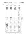
- FIG. 6is a block diagram of a frame structure for transmitting multiple traffic types consistent with the present invention.
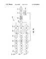
- FIGS. 7A and 7Bare block diagrams of a transmitter and receiver, respectively, consistent with the present invention.
- FIG. 8is a flow diagram of a transmission and reception process consistent with the present invention.
- FIG. 9is a block diagram of a radio port in the WLAS system of FIG. 1 consistent with the present invention.
- FIG. 10is a block diagram of a subscriber unit in the WIAS system of FIG. 1 consistent with the present invention.
- a WIAS system architecture consistent with the present inventionincludes major network functional elements, a radio interface, and important radio port and subscriber unit subsystems.
- the WIAS systemprovides an efficient means of supporting a wide variety of traffic types, ranging from broadband data pipes of up to 17.5 Mbps, to 32 kbps ADPCM voice.
- the WIAS systemis designed with the flexibility to support both delay-tolerant and low-latency data, including voice and real-time multimedia
- the WIAS systemis resistant to multipath, and is tolerant of interference and spectrum reuse in unlicenced bands.
- FIG. 1is a block diagram of a wireless Internet access system (WIAS) 100 consistent with the present invention.
- WIAS 100can be designed to use existing networks, such as a 100/10 BaseT Ethernet network, an A synchronous Transfer Mode (ATM) network, a Fiber Optics network, and a Token Ring network.
- ATMA synchronous Transfer Mode
- WIAS 100can be designed to use other networks as well, the following description will focus on the Ethernet implementation as a preferred implementation.
- WIAS 100includes one or more islands 125 , each island 125 including one or more subnets 120 .
- Subnet 120includes an existing network (not shown), such as the 100/10 BaseT Ethernet LAN, and a plurality of radio ports (RP)) 110 attached to the network.
- RPradio ports
- At least one of the RPs 110 in each subnet 120includes mobility agent (MA) functionality, shown as MA 115 in FIG. 1 .
- MAmobility agent
- RPs 110establish radio or wireless links with a plurality of subscriber units (SUs) 105 , and also manage the termination and modification to the links.
- Each SU 105can be homed to an existing subnet 120 by assigning it a permanent or home Internet Protocol (IP) address (H.IP).
- IPInternet Protocol
- a mobility agentcan be independent of any other radio ports and exist as a virtual subnet, as shown by MA 117 in FIG. 1 .
- MA 117acts as a home agent (HA) for SUs 105 not assigned to a real subnet, i.e., a subnet with multiple subscriber units in addition to a mobility agent.
- HAhome agent
- each island 125includes elements for routing and processing information to and from subnets 120 .
- These elementsinclude a router 130 , a network management and monitoring system (NMM) 135 , a gateway 140 , and a telephone gateway 145 .
- Router 130is a well known device for routing information to and from the network, and may be an existing part of the network.
- NMM 135provides a single entity for operations, administration, and maintenance of WIAS 100 .
- Gateway 140represents an interface between the existing network and external communication systems and often includes firewall protection for the network.
- Telephone gateway 145provides a mapping between mobile identification number (MIN) and Internet Protocol (IP) addresses for SUs 105 that are capable of supporting telephony functions. In addition, telephone gateway 145 can act as a voice IP modem for calls in progress.
- MINmobile identification number
- IPInternet Protocol
- Data from gateway 140can be transmitted to an external communication system, such as the Internet 160 , while data from telephone gateway 145 can be transmitted to a public switched telephone network (PSTN) 160 . Data can also be transmitted between the Internet 160 and PSTN 150 via another telephone gateway 155 . As shown in FIG. 1 , a standard telephone 165 can be connected to PSTN 150 , and an IP phone 170 can be connected to the Internet 160 .
- PSTNpublic switched telephone network
- WIAS 100One of the functions of WIAS 100 is to support mobility for SUs 105 .
- WIAS 100supports two levels of mobility, allowing mobility within a subnet as well as roaming among foreign subnets that may be located in different islands. These levels of mobility are scaled so that a minimum amount of equipment is required to deliver the first level of intra-subnet mobility. As wider area mobility is required, additional functional units are added. Mobility functions include registration, location, and hand-off capabilities.
- the first level of mobility involving mobility within subnet 120is entirely managed by RPs 110 .
- An advantage to this approachis that small offices using LANs that comprise a single subnet 120 can use WIAS 100 by simply attaching RPs 110 to the existing 100/10 BaseT LAN. As WIAS 100 expands, additional mobility functions can be added to support inter-subnet roaming.
- an SUWhen an SU is activated, it scans all of the available channels in WIAS 100 , searching for the RP having the strongest available signal.
- multiple RPsmay share a carrier, which is taken into account by a candidate carrier measurement algorithm within the SU.
- the algorithmmeasures the received signal strength (RSS) from each RP.
- RSSreceived signal strength
- the SUtunes to other frequency bands. If an RP is detected, SU stores in a table the RSS associated with the detected RP. Each table entry may be valid for a short period of time (e.g., 2 seconds).
- the SUtunes to the frequency of the RP with the highest RSS in the table and attempts to establish communication with that RP.
- the SUattempts to attach to that RP by transmitting a local registration message on a random access slot (RAS) channel, which is discussed in more detail herein.
- the registration messageinforms the RP that the SU is attaching to the network at that point.
- the RPprovides its physical address in response to any address resolution protocol (ARP) requests for the SU's IP (SU.IP) address.
- ARPaddress resolution protocol
- the RPtransmits a gratuitous ARP broadcast message throughout its subnet, allowing all other hosts on the subnet to update their ARP caches to reflect the current location of the SU.
- an SUregisters with a radio port RP 1 in step 1 . If an SU loses contact with RP 1 during transmission or reception of a packet, such as due to moving to a new location, or at periodic intervals when the SU is idle, the SU repeats the candidate carrier measurement procedure searching for better RP links. As shown in step 2 , if the SU locates a new RP (RP 2 ), it transmits a local registration message on the RAS.
- RP 2new RP
- RP 2If RP 2 , already has an ARP entry cached which links the IP address of the registering SU (SU.IP) with the physical address of RP 1 (RP 1 .PA), then RP 2 transmits a gratuitous ARP to map the IP address of the SU with the physical address of RP 2 for all other hosts on the subnet. When RP 1 receives this ARP, it expires its previous registration and discontinues proxy ARP replies for the SU.
- each subnetincludes a mobility agent (MA).
- MAmobility agent
- HAhome agent
- FAforeign agent
- the MAnever acts as a foreign agent, but may act as a home agent for SUs that are homed to the virtual subnet.
- SUs homed to real subnetsis preferable when large subnets are used with extensive intra-subnet traffic.
- Using SUs homed to a virtual subnetis also preferable when many small subnets are present, when SUs spend a lot of time roaming from one subnet to the next, or when network traffic is not contained predominantly within a subnet.
- An SU's home subnetis the subnet having a mask corresponding to the SU's permanent IP address (H.IP).
- a foreign subnetis any other subnet where an SU might find itself. Either or both of the homing approaches can be used as appropriate. Either way, an SU that is roaming in a foreign subnet (which is always the case when a virtual subnet is used), is assigned a Care-of-Address (COA.IP) that is local to the foreign subnet.
- COA.IPCare-of-Address
- an entire IP packetwhich may include the IP address of the sender and the recipient, is included as the payload of another IP packet with a new sender and recipient address.
- a packetarrives at the “home” address of a mobile host when the mobile host is temporarily relocated to another IP subnet with a known forwarding address, the packet may be encapsulated with the temporary address of the mobile host in the new subnet as the “recipient” and the home address as the “sender.”
- the packetis routed to the mobile host, which strips off the encapsulation to recover the original message.
- WIAS 100supports full route optimization, assuming a suitable corresponding host (CH), i.e., the node sending packets to a roaming SU.
- CHcorresponding host
- the first IP packet sent to a roaming SU from a CHis routed through the HA. If the CH supports route optimization, then subsequent packets are sent by the CH directly to the SU at its Care-of-Address, COA.IP. If the SU moves from one subnet to the next, then as the SU is registered in the new subnet, a new COA.IP address is obtained, and the bindings are updated with the SU's HA as well as any CHs capable of route optimization.
- COA.IPCare-of-Address
- the registration procedure for intra-subnet roamingis modified slightly to accommodate inter-subnet roaming. Subscribers in foreign subnets always register using their H.IP address.
- an RPreceives a registration message from an SU that is not homed to that RP's subnet, the RP sends a mobility resolution request to the MA in its subnet.
- the MAsends a message to the SU's home agent requesting authentication for the SU and provides a Care-of-Address (COA.IP) that the HA can use for forwarding.
- COA.IPCare-of-Address
- the MAassigns the COA.IP address to the SU, which uses the COA.IP for the duration of its stay within the foreign subnet.
- WIAS 100Another function provided by WIAS 100 is to support full seamless handoff for all types of traffic. Unlike PCS systems where a subscriber typically only has a single voice channel, links in WIAS 100 can comprise numerous connection-oriented traffic streams.
- the handoff process for WIAS 100involves a negotiation of radio resources at the new radio port to ensure that low-latency channels are set up with priority and that error sensitive data is delivered in its entirety.
- FIG. 3shows a flow diagram of a handoff process consistent with the present invention.
- an SUsuccessfully negotiates a registration with a new RP (step 305 ).
- the registration messageincludes the IP address of the RP to which the SU was previously linked (if any).
- the new RP(RP 2 ) sends a notification to the old RP (RP 1 ) requesting a handoff over the 100/10 BaseT network (step 310 ).
- RP 1responds with a message to RP 2 containing the complete TCP/UDP (transmission control protocol/user datagram protocol) Port-to-logical channel mapping (TLM) information for the SU, along with the remainder of any partially delivered downlink data (step 315 ).
- TCP/UDPtransmission control protocol/user datagram protocol
- TLMPort-to-logical channel mapping
- RP 1tears down all logical channels associated with the SU (step 320 ), while RP 2 examines its available radio resources and attempts to establish logical channels for each TCP port connection (step 325 ). Based on channel priority, such as constant bit rate (CBR) voice traffic first and delay tolerant packet data last, RP 2 assigns new logical channels for each TCP port connection (step 330 ). If any logical channels cannot be assigned, some connections may fail based on TCP time-out settings (step 335 ). However, all successful logical channels will remain in place.
- CBRconstant bit rate
- each radio portcould be implemented to always support some voice and packet data capabilities. By always supporting some voice capabilities, a radio port does not need to rearrange its frame structure to support an arriving voice cormection.
- the packet access mechanisms in WIAS 100may be sub-optimal for dedicated data streams, they can temporarily support any TCP/IP data connection at a reduced quality of service (QoS) until a suitable logical channel can be established.
- QoSquality of service
- WIAS 100can handle voice and other real-time multimedia traffic.
- VOIPvoice-over-IP
- WIAS 100can use the H.323 protocol framework as described in the ITU-T's H.323 International Telecommunications Union, “Visual Telephone System and Equipment for Local Area Networks which Provides a Non-Guaranteed Quality of Service,” Recommendation H.323, Telecommunication Standardization Sector of ITU, Geneva, Switzerland, May 1996, which is designed for real-time, multipoint, multimedia videoconferencing on packet-switched networks, and which supports IP-to-PSTN interworking.
- the inventionincludes at least two broad categories for supporting as voice traffic in WIAS 100 .
- the first categoryuses a separate voice interface, shown as voice network 175 with direct connection to PSTN 150 , such as a multimedia cordless phone scenario.
- voice network 175with direct connection to PSTN 150 , such as a multimedia cordless phone scenario.
- voice network 175with direct connection to PSTN 150 , such as a multimedia cordless phone scenario.
- Mobilitymay be supported by the voice network, the 100/10 BaseT data network, or both.
- the other category for supporting voice traffic in WIAS 100integrates voice and data on WIAS 100 .
- Multiple scenarios exist for integrating voice and data on WIAS 100including: (a) a connection from SU 105 to PSTN telephone 165 (PSTN-Phone) via an internal telephony gateway (TGW) 145 , which provides the network interface between the IP-based WIAS 100 and PSTN 150 , with a pass-through connection on voice network 175 ; (b) a connection from SU 105 to IP telephone 170 (IP-Phone) through the Internet 160 without any PSTN connectivity; and (c) a connection from SU 105 to PSTN-Phone 165 via Internet 160 and an external TGW 155 that interworks Internet 160 with PSTN 150 .
- IP-PhoneIP telephone 170
- WIAS 100can use the IP-based Real Time Protocol (RTP) H. Schulzrinne et al, “RTP: A Transport Protocol for Real-Time Applications,” Request for Comments (Proposed Standard) RFC 1889, Internet Engineering Task Force, December 1997, which handles voice traffic over User Datagram Protocol (UDP) connections.
- RTPis a thin protocol that provides support for timing reconstruction, loss detection, security, and content identification.
- RTPA Transport Protocol for Real-Time Applications
- RFC 1889Internet Engineering Task Force
- H.323supports the ITU-T defined H.245 connection control protocol running on top of TCP for call connection and control.
- H.245can provide an alternative to RTP for DTMF signaling.
- WIAS 100can be implemented as a dynamic time division duplex/time division multiple access (D-TDD/TDMA) system. Such a system uses a non-periodic, variable frame structure.
- FIG. 6shows a frame structure for use in WIAS 100 consistent with the present invention.
- data transmissionsare each broken up into a series of phases, each phase lasting for a particular period of time, such as 30 seconds.
- Each phaseconsists of a number of superframes. For a superframe having a duration of 250 milliseconds (msec), a 30 second phase would include 120 superframes.
- Each superframeis made up of, for example, 64 frames, which would correspond to approximately 3.9 msec per frame for a 250 msec superframe.
- Each frameincludes a number of time slots, such as sixteen, including both uplink and downlink slots. The number of uplink and downlink slots used in a frame can vary from one superframe to the next.
- Each framemust include a downlink node control channel (NCC), which, by definition, starts each frame.
- NCCdefines the frame format for the phase, including the length and make-up of each frame.
- all uplink and downlink time slotsare defined in reference to the immediately preceding NCC.
- the NCCcontains paging information, which is used to inform SUs that there are incoming connections directed to a particular SU, as well as channel or slot assignments.
- the NCCalso provides acknowledgments and word error indications (ACKS/WEI) for the uplink slots.
- ACKS/WEIacknowledgments and word error indications
- the NCCcontains a frame descriptor which informs SUs about what types of logical channels are supported by the RP along with the associated time slots. There is only one NCC per frame.
- Each framemust also include an uplink random access slot (RAS), which, by definition, ends each frame.
- RASis subdivided into a number of frequency subchanneIs, each with 32 subcarriers.
- the first block of subchannelsis set aside for downlink acknowledgments (ACK/NAK).
- Other blocksare set aside for access and registration messages.
- Access messagesare used when an SU requests a UDC (uplink data channel), UVSC (uplink video stream channel), or UMVC (uplink multiplexed video channel), discussed below.
- Registration messagesare used by an SU to announce that it is connected to the network at a particular RP. Both access and registration messages are sent using a set of 32 subcarriers confined to a block which is selected at random to reduce collisions.
- the RASis also used by subscriber units to generate uplink time slot requests.
- the framepreferably includes all downlink time slots first (from the RP to the SU), followed by uplink time slots. Each time slot is defined by its distance in time from the preceding NCC.
- the DDCis the basic downlink data ABR (available Downlink Data channel. Once established, it is bit rate), VBR Channel dedicated to traffic for a particular (variable bit subscriber for a specified number of rate) frames. There are typically several High Latency DDC slots per frame. This channel High Speed supports bulk download data including FTP and large Web downloads.
- DPSCThe DPSC is a multiplexed downlink ABR Downlink Packet data stream containing data for High Latency Stream Channel multiple uses, all of which monitor Low Rate the streaming channel. Each packet on the DPSC is identified for one of a plurality of listeners. The purpose of this channel is to support short inbound messages.
- the DVSCis essentially the same as CBR (constant Downlink Video the DDC, except that it is assigned bit rate), ABR, Stream Channel with higher priority, meaning that VBR there will be fewer delays incurred.
- Low LatencyThis channel supports high rate data High Rate streaming applications, such as video.
- DMVCThe DMVC contains downlink data CBR Downlink of multiplexed voice channels.
- a Low Latency Multiplexed number N voice callsshare the Voice Rate Voice Channel DMVC by using it once every N frames. For example, in a 10.3 MHz implementation, each slot supports 1 Mbps. Then 16 SUs multiplex voice signals onto the DMVC by using it once every 16 frames, providing 32 kbps at 1 ⁇ 2 rate coding.
- a DMVCis always paired with an uplink UMVC.
- UDCThe Uplink Data Channel is used to ABR Uplink Data support high data rate uplink data High Latency Channel traffic with medium to high delay High Rate tolerance. UDC slots are assigned to a particular subscriber and last over multiple frames.
- UVSCThe UVSC provides a low latency, CBR, ABR, Uplink Video high data rate channel for delay VBR Stream Channel sensitive, high data rate streaming Low Latency data applications, such as video.
- High Rate UPACThe UPAC channel provides CSMA ABR Uplink Packet (carrier sense multiple access) High Latency Access Channel uplink packet service for short Low Rate uplink messages without the channel setup overhead involved in the UDC.
- UMVCThe UMVC is the uplink side of the CBR Uplink DMVC. Low Latency Multiplexed Voice-Rate Voice Channel
- the RPmay choose to support any combination of DDC, DPSC, DVSC, and DMVC channels on the downlink.
- the RPcan support the UDC, UPAC, WVSC, and UMVC channels.
- each radio portis preferably implemented to support voice and packet data capabilities. Accordingly, a typical configuration of a frame would use at least one DPSC/UPAC pair and one DMVC UMVC pair. The remaining 10 time slots in the frame might be allocated to DDC and UDC channels.
- the RPis free to change the make up of the frame, including multiplexed voice slots, packet channels, etc., once per 30-second phase. From a fixed total number of DDC/UDC channels, the RP is free to change the fraction allocated to the downlink and uplink once per superframe (250 msec). The RP can also change the DVSC/UVSC ratio at the start of each superframe. Whenever the RP changes the DDC/UPC ratio, DVSCIUVSC ratio or frame make-up, the RP is responsible for ensuring that all affected traffic is seamlessly moved, so that a logical channel that is in-use is not deallocated.
- RPsgenerate a minimum amount of co-channel interference by transmitting only as necessary.
- RP frequency selection functionsare autonomous.
- Fifth, RPscan “camp” on the frequency of another inactive RP, in essence sharing its channel.
- Sixth, Two low-activity RPscan share a frequency channel by sacrificing sleep mode capabilities.
- SUsdo not expect an RP to be present over long periods of time if they are inactive. In other words, if an SU is idle in a cell corresponding to a very lightly loaded RP, the SU will awake from sleep cycles in synchronization with the selected RP; however, if the SU awakes to find that the RP has left the channel, the SU will start to search for a new candidate RP (and possibly find the same RP on another frequency) in an orderly manner.
- each RPseizes a carrier frequency by scanning a set of channels in a band of operation. The RP then selects a channel of operation which either presents the minimum amount of interference or a power level below a specified threshold. RPs can be instructed to operate in the low, middle, or high U-NII bands, or any combination of these bands.
- the U-NII bandsinclude the spectrum from 5.150 to 5.350 GHz and from 5.725 to 5.825 GHz, which corresponds to a total spectrum of 300 MHz.
- WIAS 100can be implemented in other bands as well. For example, by complying with Listen-Before-Talk rules, WIAS 100 could be implemented for use in 1910-1920 MHz asynchronous unlicenced PCS bands. Alternatively, WIAS 100 could be used in a private spectrum, including the licenced PCS band (1850-1910 and 1930-1990 MHz). RPs preferably monitor each candidate channel for at least one superframe before selecting a channel of operation.
- the process of scanning the channels in a band and selecting a candidate channelis dependent upon the bandwidth with which an RP is operating. If an RP is operating with a 2.6 MHz bandwidth, it begins searching for frequencies in the lowest 18 MHz within each 100 MHz band, and only attempts to search outside of this region if there are no acceptable channels: in the lowest 18 MHz. Channels are spaced 1.5 MHz apart, with channel number 1 beginning 1.5 MHz from the bottom of the band. Channels 1-11 comprise the initial search set. The total search set can include the entire band, which contains 66 channels (1 . . . 66).
- an RPIf an RP is operating with a 5.2 MHz bandwidth, it begins searching for a channel between 18 MHz and 51 MHz from the bottom edge of the band. RPs consider two channels at a time, for a search spacing of 3 MHz.
- the initial search setincludes channels, 14, 16, 18, . . . , 32 for 10 possible candidate channels. If an RP cannot find a suitable channel in the initial search set, it may search in other channels, resulting in a total set of 32 channels (2,4,8, . . . , 62,64).
- an RPIf an RP is operating with a 10.3 MHz bandwidth, it begins searching for a channel between 51 and 100 MHz from the bottom edge of the band. RPs consider 4 channels at a time, for a search spacing of 6 MHz. The initial search set includes seven channels: 38, 42, 46, 50, 54. 58, 62. If the RP does not find a channel within one of these bands, it may search the entire set of 16 channels (2,6,10, . . . ,58,62).
- an RPbegins searching for a channel between 51 and 100 MHz from the bottom edge of the band.
- RPsconsider 8 channels at a time, for a search spacing of 12 MHz.
- the initial search setincludes three channels: 42, 50, and 58. If the RP does not find a channel within one of these bands, it may search the entire set of 7 channels (10,18,26,34,42,50,58).
- WIAS 100incorporates power control. Power control is performed using both open loop and closed loop approaches.
- open loop approachSUs set their initial transmit power based on received downlink power, so that the SU provides adequate signal strength at the RP receiver.
- closed loop approachthe RP can direct an SU to increase or decrease its power level as appropriate.
- the NCCIn order to support sleep-modes, the NCC recurs at least once per superframe, at the very beginning of the superframe. The NCC is free to transmit pages more frequently than this, but the NCC must transmit pages for all “sleeping” SUs as well as any unresolved pages from the previous superframe, beginning at the start of the next superframe. SUs, regardless of their sleep state, are required to monitor the NCC at the beginning of each superframe, along with subsequent NCCs until the NCC indicates that it has flushed all pending pages.
- WIAS 100depends on autonomous frequency selection by each RP
- the NMMhas the ability to instruct any RP-to either relinquish its channel, or acquire a specific frequency channel.
- All active radio portsregardless of traffic level, transmit an NCC burst once per superframe. This allows nearby SUs to access uplink channels.
- an RPWhen an RP has no traffic for a phase, then it marks itself as idle. Idle RPs continue to transmit one NCC burst per superframe. SUs may register with the RP without it becoming active. The NCC transmitted by an idle RP contains a marker indicating that it is idle. A monitoring RP that cannot find an acceptable frequency channel elsewhere can begin to transmit its NCC on the same carrier used by an inactive RP. If either the incumbent RP or the newly arriving RP becomes active, then the active RP transmits a message over the Ethernet network to the other RP requesting it to give up the channel. Since idle RPs transmit in a periodic fashion (one burst every superframe), each RP that starts to share a channel with other idle RPs should adjust its superframe timing to avoid colliding NCCs on the downlink.
- Two active RPscan also share a frequency band through another means.
- the networkcan disable sleep modes and operate in an a periodic mode. In this mode, rather than transmitting the NCC once (or more) per superframe, each RP must transmit its NCC no more than 250 msec from the beginning of the previous NCC. Before transmitting any frame, each RP monitors the channel for 200 microseconds ( ⁇ s). If the channel is not being used, then a frame commences, beginning with the NCC. At the end of the frame, the RP must wait at least 1 msec before attempting to transmit again. Following any unsuccessful transmission attempt, a random, increasing back-off period is imposed in a CSMA/CA fashion. If an RP goes for 250 msec without transmitting the required NCC, then the RP must attempt to locate another frequency on which to operate.
- the NMMcan manually instruct any RP, as required, to perform a controlled shut down. Subsequently, RPs can either acquire frequency channels automatically, or specific channels can be assigned as directed by the NMM.
- WIAS 100preferably transmits information between SUs and RPs using Orthogonal Frequency Division Multiplexing (OFDM), which uses a large number of simultaneous subcarriers, each of which is modulated using a low symbol rate.
- FIGS. 7A and 7Brespectively show a block diagram of an OFDM transmitter 200 and an OFDM receiver 250 consistent with the present invention.
- a very low symbol rateis used on a number of subcarriers.
- the per-subcarrier symbol rateis low enough that time-dispersion does not lead to significant inter-symbol interference (ISI).
- ISIinter-symbol interference
- FIG. 8shows a flow diagram of the operation of the OFDM transmitter/receiver of FIGS. 7A and 7B consistent with the present invention.
- IFFTinverse fast Fourier transform
- FFTfast Fourier transform
- each of the antenna in the array of antennasis extracted (step 820 ).
- a vectoris then generated for each subcarrier based on the extracted responses (step 825 ).
- Each vectorcomprises a number of elements equal to the number of receiving antennas.
- the elements in the vector of a particular subcarrierrepresent the extracted responses of the receiving antenna to that particular subcarrier.
- the phase difference between each pair of adjacent subcarriersis calculated by performing a mathematical operation, such as the dot product, on the vectors of the adjacent subcarriers (step 830 ). Once the phase difference between each pair of adjacent subcarriers is known, the symbols which had been used to phase modulate each of the subcarriers can be determined (step 835 ). The phase encoding of the subcarriers with the symbols and the subsequent decoding of them is described in more detail below.
- r(t)is the pulse shape applied to the transmitted waveform.
- each burstcontains a single OFDM symbol period.
- the transmitterdoes not transmit for some period of time until the next burst.
- the summation partshown as summation 208 in FIG. 7A , represents the result of applying the subcarriers and the symbols Z i to an IFFT 206 and modulation/mapping 204 in FIG. 7 A.
- This summationis then modified by r(t), which is represented by shape 210 .
- the resulting waveformis then converted to an analog signal by digital-to-analog (D/A) converter 212 , unconverted by U/C 214 , and transmitted by antenna. 216 .
- D/Adigital-to-analog
- the symbols Z iwhich represent the data being transmitted, are used to phase modulate each subcarrier using differential encoding, such as frequency domain differential quadrature phase shift keying (FD-DQPSK).
- Each pair of bitsis then encoded as the difference between the phases of two adjacent carriers, ( ⁇ i ⁇ i-1 ).
- the minimum spacing between carriersis equal to 1/T s , where T s is the length of the time window used to sample the signal at the receiver.
- the SUs and RPsmay use multiple antennas to receive the transmitted signal. Having a multipath channel, however, can lead to distortion of the received signal. Since the SUs and RPs in WIAS 100 preferably use multiple receiving antennas, shown as antennas 252 of receiver 250 in FIG.
- Each element of the vector h(t, ⁇ )represents the channel between the transmitter and one element of the receiving array.
- the modeluses N L discrete paths from the transmitter to the receiver, each of which takes the form of a single plane wave at the receiving array.
- Each componentis characterized by its direction-of-arrival (DOA), ⁇ 1 , the scalar path gain, ⁇ l , the path delay relative to the first arriving path, ⁇ l , the Doppler shift, ⁇ 1 , and the additional fixed phase factor, ⁇ 1 .
- DOAdirection-of-arrival
- ⁇ 1the scalar path gain
- ⁇ lthe path delay relative to the first arriving path
- ⁇ 1the Doppler shift
- ⁇ 1the additional fixed phase factor
- the signal received by each of the antennas 252is down converted by D/C 254 , converted to a digital signal by A/D converter 256 , and pulse-shaped by shape 258 .
- the signal received at each antennais then separated into each subcarrier by FFT 260 .
- FFT 260To extract the symbol from a subcarrier, a vector v k is formed using delta function 262 , multiplier 264 , and summer 266 .
- Each element of vector v krepresents the response of one of the antennas in the array to subcarrier k Because there is a non-zero ramp-up and ramp-down time associated with the subscriber amplifier and in order to minimize inter-subcarrier interference, r(t) can be written as a square root raised cosine pulse shape (the time analog of the pulse shaping represented by shape 210 in FIG.
- the phase difference between adjacent subcarrierscan be calculated using detector 270 .
- a computationally simple technique, for demodulating multi-sensor frequency-differential signals,is to form the inner product between v k for successive sub-carriers. This approach is analogous to the time-domain differential demodulator that multiplies successive time symbols to estimate the phase between symbols.
- the carrier-to-carrier phase shiftis estimated by multiplying spatial vectors for successive carriers together.
- ⁇ k⁇ n ⁇ k H ⁇ n ⁇ k - 1 ( 16 ) Since the information is encoded using the difference between the phase of successive symbols, Y k is a decision variable for the modulation scheme.
- Y kis a biased estimator, even when the noise is negligible.
- the technique described hereis used for the uplink in WIAS 100 .
- the downlink in WIAS 100uses a similar technique, however a cyclic prefix is appended to each burst.
- the cyclic prefixmay be implemented by prepending a transmitted data symbol with appropriate samples from the end of the symbol so that the resulting waveform is the circular convolution of the channel impulse response with the transmitted data, thus simplifying the FFT processing at the receiver.
- Differential encodinghas several advantages over non-differential modulation.
- the modulation techniqueis robust to phase variations introduced by the channel. Phase variations due to the channel may be significant over the entire bandwidth of the signal (N c ⁇ f) but are likely to be small from one subcarrier to the next.
- Differential encodingalso provides an efficient technique to combine signals from multiple antenna elements in a nearly optimal manner.
- differential encodingperforms slightly worse than non-differential encoding over AWGN channels, the difference is less pronounced in multipath channels.
- N cthe number of subcarriers, can be much larger than the six subcarriers used in the above example. Typical values range from 64 to 1024 subcarriers. For example, if the channel of operation is 5.15 GHz and the number of subcarriers is 64 with a separation of 5 KHz, the subcarriers would range from 5.15 GHz for the first subcarrier to 5.15 GHz+315 KHz for the last subcarrier.
- a problem common to all OFDM schemesis the issue of peak-to-average power ratio (PAR), also called the crest factor.
- PARpeak-to-average power ratio
- the total energy in each burstwill be a constant value regardless of the modulating data.
- the peak instantaneous power of the burstif unaddressed, can be as much as N c times the average power of the burst.
- the average poweris defined as the energy per burst divided by the burst duration. Since N c is large, this can produce unacceptably high peak power values, resulting in distortion of the transmitted signal unless extremely expensive, high dynamic range transmit amplifiers are used, which tend not to be power efficient.
- each burstsets aside N p subcarriers for crest factor reduction (CFR).
- CFRcrest factor reduction
- Systematic algorithms to find optimal sets of N p carriers, which result in a minimum PARare not easily implemented.
- N c -N p data subcarriersare used with N p PAR subcarriers, using a set of N p modulating symbols, ⁇ X i ⁇ , for the partitioned CFR subcarriers.
- a random set of values ⁇ X i ⁇is drawn from a QPSK symbol set, and s p (t) is computed.
- the Peak-to-Average power Ratiois computed for the resulting burst, s t (t). If the PAR is less than T pp , then the set of PAR reduction symbols, ⁇ X i ⁇ , are accepted and s t (t) is transmitted. If the PAR is greater than the threshold T pp , then a new set of ⁇ X i ⁇ is selected and the process is repeated. The set of ⁇ X i ⁇ which gives the minimum PAR over the search set is always maintained.
- Table 3shows suggested system specifications from WIAS 100 for the different channel bandwidths. These system specifications are merely preferences, and should not be construed as limiting or unchangeable.
- not all terminalssupport all data rates.
- portable subscriber terminalsmay only support 2.6 and 5.2 MHz bandwidths.
- desktop systemscan support up to 10.3 MHz, and links requiring substantial bandwidth can support 20.6 MHz bandwidth.
- FIG. 9shows a block diagram of RP 110 consistent with the present invention.
- RP 110comprises a POTS/ISDN Interface Module 900 , an Ethernet Transceiver 905 , an IP Interceptor 910 , a plurality of TCP/UDP Port to Logical Channel Mapping Modules (TUPLCM) 915 , a Mobility Management Module 920 , a Security Management Module 925 , Logical Channel Modules (LCM) 930 , 935 , and 940 , a Logical Channel Multiplexing Module 945 , a Modulation/Encoding/Crest Factor Reduction Symbols Module (MECFR) 950 , a Transmitter Antenna Selector 955 , OFDM Baseband Processing Modules 960 , 964 , and 968 , RF Transceivers (RF XCVR) 970 , 975 , and 980 , a Multi-Antenna Combining Module 985 , a Detector/Receiver 990
- POTS/ISDN Interface Module 900maps an input serial data steam to an output data stream 902 that may include a modulation data stream that can be transmitted over a POTS line or a digital data stream that can be transmitted over an ISDN line.
- the output data stream 902which is received by TUPLCM 915 , may be bi-directional for either POTS or ISDN modes.
- Ethernet Transceiver 905maps data from an Ethernet cable to a serial data stream 908 , which includes Internet Protocol (IP) packets and is received by IP Interceptor 910 .
- IP Interceptor 910then routes the IP packets in serial data stream 908 to TUPLCM 915 .
- Each TUPLCM 915which is associated with a subscriber, receives either the routed serial data stream 908 or data stream 902 and routes the traffic to individual LCMs 930 , 935 , and 940 .
- TUPLCM 915associates each LCM 930 , 935 , and 940 with a different TCP or UDP port number.
- TUPLCM 915may be implemented as an object using software. As such, TUPLCM 915 may be created and deleted as needed to match the number of active subscribers currently associated with each RP.
- Mobility Management Module 920maps Care-Of IP addresses to actual IP addresses to support mobile IP.
- Security Management Module 925performs authentication to ensure that a subscriber attempting to access WIAS 100 is authorized.
- Each LCM 930 , 935 , and 940includes a first bidirectional input port that connects to the TUPLCM 915 . This first input port supports data for a particular TCP/UDP port associated with a particular subscriber. The data flowing into the first input port is buffered for transmission through an output port. Each LCM 930 , 935 , and 940 also includes a second input port that connects to Logical Channel Multiplexing Module 945 .
- Serial data at the second input portis buffered for transmission to TUPLCM 915 via the first input port.
- Each LCM 930 , 935 , and 940buffers delay-tolerant transmitted data from the first input port until a proper automatic repeat request (ARQ) response is received from the subscriber. If a negative acknowledgment (NAK) is received, then each LCM 930 , 935 , and 940 re-transmits the buffered data through the output port.
- delay-sensitive datasuch as voice, may not be buffered.
- LCMs 930 , 935 , and 940may be implemented as objects using software so that each LCM 930 , 935 , and 940 can be created or deleted easily to support data streams for each subscriber.
- Logical Channel Multiplexing Module 945receives data streams from the outputs of LCM 930 , 935 , and 940 , and multiplexes the data streams onto a single data stream 948 , which is received by MECFR 950 .
- the amount of data taken from each data streamis matched to the number of bits contained in the data burst for each data type.
- MECFR 950groups sets of bits in the data stream 948 and generates as output a data stream 953 .
- MECFR 950adds to the data stream 948 Forward Error Control (FEC) encoding to control errors and Crest Factor Reduction (CFR) bits to minimize the peak-to-average ratio of the transmitted data symbols, thus reducing the required dynamic range of RP 110 and improving transmission efficiency.
- MECFR 950groups together blocks of encoded bits, and performs an inverse fast Fourier transform (IFFI) on the data stream 948 to form Orthogonal Frequency Division Multiplexing (OFDM) symbols.
- Transmitter Antenna Selector 955then maps the resulting data stream 953 onto one of RF XCVR 970 , 975 , and 980 .
- IFFIinverse fast Fourier transform
- Each XCVR 970 , 975 , and 980includes a digital input, a digital output, and an antenna port.
- Each XCVR 970 , 975 , and 980converts digital data from the input into an analog signal, modulates onto an RF carrier, amplifies, filters, and transmits the resulting signal through the antenna port. Data received from each antenna is filtered, amplified, down-converted, digitized, and made available at the output.
- Each OFDM Baseband Processing Module 960 , 964 , and 968receives digitized symbols from the output of one XCVR 970 , 975 , and 980 , extracts timing information, using a fast Fourier transform (FFT), extracts the symbols modulated onto each individual subcarrier, and generates an output data stream.
- FFTfast Fourier transform
- Multi-Antenna Combining Module 985receives the output data stream generated by each OFDM Baseband Processing Modules 960 , 964 , and 968 , and using the differential OFDM multiple antenna combining technique described earlier, generates a single combined data steam 988 .
- Detector/Receiver 990converts the symbols in the data steam 988 into a binary digital data stream, and removes Crest Factor Reduction (CFR) bits and error control encoding bits in the data stream 988 , resulting in a data stream 993 .
- Logical Channel De-Multiplexing Module 995then receives and routes the binary digital data stream 993 to the second inputs of LCMs 930 , 935 , and 940 .
- FIG. 10shows a block diagram of SU 105 consistent with the present invention.
- SU 105comprises a SeriaVPCMCLA/Pilot Interface 1000 , a plurality of TCP(UDP Port to Logical Channel Mapping Modules (TUPLCM) 1005 , a Mobility Management Module 1010 , a Security Management Module 1015 , Logical Channel Modules 1020 , 1025 , and 1030 , a Logical Channel Multiplexing Module 1035 , a Modulation/Encoding/Crest factor Reduction Symbols (MECFR) 1040 , RF Transceivers (RF XCVR) 1050 and 1055 , OFDM Baseband Processing Modules 1045 and 1060 , a Multi-Antenna Combining Module 1065 , a Detector/Receiver 1070 , and a Logical Channel De-Multiplexing Module 1075 .
- TCP(UDP Port to Logical Channel Mapping Modules (TUPLCM) 1005a Mobility Management Module 1010
- Serial/PCMCIA/Pilot Interface 1000interfaces with a physical interface corresponding to that of an RS- 232 serial port, PCMCIA card, 3com Palm Pilot interface, or any other similar interface, and generates an IP packet data stream 1003 .
- TUPLCM 1005receives and routes the IP packet data stream 1003 to one of LCMs 1020 , 1025 , and 1030 .
- TUPLCM 1005associates each LCM 1020 , 1025 , and 1030 with a different TCP or UDP port number.
- Mobility Management Module 1010maps Care-Of IP addresses to actual IP addresses to support mobile IP.
- Security Management Module 1015performs authentication to ensure that a subscriber attempting to access WIAS 100 is authorized.
- Each LCM 1020 , 1025 , and 1030includes a first bi-directional port connects to TUPLCM. 1005 .
- Tis interfacesupports data for a particular TCP/tDP port. The data stream to flowing into the first port is buffered for transmission through a second port. Serial data received from Logical Channel Multiplexing Module 1035 via a third port is buffered for transmission to TUPLCM 1005 via the first port.
- Each LCM 1020 , 1025 , and 1030buffers delay-tolerant transmitted data from the first port until the proper automatic repeat request (ARQ) response is received from the subscriber.
- ARQautomatic repeat request
- each LCM 1020 , 1025 , and 1030re-transmits buffered-data at the second port.
- delay-sensitive datasuch as voice, may not be buffered.
- Each LCM 1020 , 1025 , and 1030may be implemented in software.
- Logical Channel Multiplexing Module 1035receives data streams from the second ports of LCM 1020 , 1025 , and 1030 , and multiplexes these data streams onto a single data stream 1038 .
- the amount of data taken from each data streamis matched to the number of bits contained in the data burst for each data type.
- MECFR 1040which receives the data stream 1038 , groups sets of bits in the data stream 1038 , and adds Forward Error Control (FEC) encoding to control errors and Crest Factor Reduction (CFR) bits to minimize the peak-to-average ratio of the transmitted data symbols, thus reducing the required dynamic range of SU 105 and improving transmission efficiency.
- Blocks of encoded bitsare grouped together, and an inverse fast Fourier transform (IFFT) is performed on the data stream 1038 to form Orthogonal Frequency Division Multiplexing (OFDM) symbols.
- IFFTinverse fast Fourier transform
- OFDMOrthogonal Frequency Division Multiplexing
- Each RF XCVR 1050 and 1055includes a digital input, a digital output, and an antenna port. Each RF XCVR 1050 and 1055 converts digital data from the input into an analog signal, modulates onto an RF carrier, amplifies, filters, and transmits the resulting signal through the antenna port. Data received from the antenna port is filtered, amplified, down-converted, digitized, and made available at the output port.
- Each OFDM Baseband Processing Modules 1045 and 1060receives digitized symbols from one of RF XCVR 1050 and 1055 , extracts timing information, and using a fast Fourier transform (FFT), extracts the symbols modulated onto each individual subcarrier.
- Each OFDM Baseband Processing Modules 1045 and 1060makes the resulting data stream available at an output port received by Multi-Antenna Combining Module 1065 .
- Multi-Antenna Combining Module 1065uses the differential OFDM multiple antenna combining technique described earlier, Multi-Antenna Combining Module 1065 generates a single combined data stream 1068 .
- Detector/Receiver 1070converts the symbols in data stream 1068 into a binary digital stream, and removes the CFR bits and error control encoding bits, resulting in a data stream 1073 .
- Logical Channel De-Multiplexing Module 1075receives and routes the data bursts in data stream 1073 to the third ports of LCMs 1020 , 1025 , and 1030 .
- Peer-to-peer connectionsare easily supported in WLAS 100 . As shown in FIGS. 9 and 10 , the functionality of the SU and RP are very similar.
- one SUfor example SU 105 , simply generates an NCC burst on a frequency channel that is selected in accordance with the spectrum management described above.
- the NCC burstis specially identified as a peer-to-peer (PTP) NCC with the SUs IP address.
- PTPpeer-to-peer
- a second subscriberfor example SU 106 , can link to SU 105 by registering with SU 105 exactly as if SU 105 were an RP. This registration allows direct data, voice, or video links between subscribers, even in the absence of the WIAS network.
- WIAS 100can be implemented as a fiber distributed data (FDD) system. This implementation is particularly useful for applications in the licensed PCS bands in the United States. Although this implementation sacrifices the ability of the system to dynamically adapt to match traffic asymmetry, it eases deployments along side other FDD systems.
- FDDfiber distributed data
- the WIAS downlinkis fixed at 16 slots per frame (the NCC followed by 15 downlink user data slots).
- the WIAS uplinkis fixed at 16 slots per frame (the RAS followed by 15 uplink user data slots).
- WIAS 100can use wireless links to connect subnets. There are many existing products that operate in the high U-Nil band that can serve this purpose. Typically, such a wireless backbone would be deployed using directional antennas to provide a point-to-point link between an RP and a router. Alternatively, WIAS 100 can be used in a Multi-Hop mode. This requires multiple RF transceiver cards in the RPs, such as shown in FIG. 9 , one to provide subscriber access and one other for each multi-hop terminus.
Landscapes
- Engineering & Computer Science (AREA)
- Computer Networks & Wireless Communication (AREA)
- Signal Processing (AREA)
- Mobile Radio Communication Systems (AREA)
Abstract
Description
| TABLE 1 |
| Logical Channels |
| Logical Channel | Description | Traffic |
| DDC | The DDC is the basic downlink data | ABR (available |
| Downlink Data | channel. Once established, it is | bit rate), VBR |
| Channel | dedicated to traffic for a particular | (variable bit |
| subscriber for a specified number of | rate) | |
| frames. There are typically several | High Latency | |
| DDC slots per frame. This channel | High Speed | |
| supports bulk download data | ||
| including FTP and large Web | ||
| downloads. | ||
| DPSC | The DPSC is a multiplexed downlink | ABR |
| Downlink Packet | data stream containing data for | High Latency |
| Stream Channel | multiple uses, all of which monitor | Low Rate |
| the streaming channel. Each packet | ||
| on the DPSC is identified for one of | ||
| a plurality of listeners. The purpose | ||
| of this channel is to support short | ||
| inbound messages. | ||
| DVSC | The DVSC is essentially the same as | CBR (constant |
| Downlink Video | the DDC, except that it is assigned | bit rate), ABR, |
| Stream Channel | with higher priority, meaning that | VBR |
| there will be fewer delays incurred. | Low Latency | |
| This channel supports high rate data | High Rate | |
| streaming applications, such as video. | ||
| DMVC | The DMVC contains downlink data | CBR |
| Downlink | of multiplexed voice channels. A | Low Latency |
| Multiplexed | number N voice calls share the | Voice Rate |
| Voice Channel | DMVC by using it once every N | |
| frames. For example, in a 10.3 MHz | ||
| implementation, each slot supports | ||
| 1 Mbps. Then 16 SUs multiplex | ||
| voice signals onto the DMVC by | ||
| using it once every 16 frames, | ||
| providing 32 kbps at ½ rate | ||
| coding. Unlike the other channels, a | ||
| DMVC is always paired with an | ||
| uplink UMVC. | ||
| UDC | The Uplink Data Channel is used to | ABR |
| Uplink Data | support high data rate uplink data | High Latency |
| Channel | traffic with medium to high delay | High Rate |
| tolerance. UDC slots are assigned | ||
| to a particular subscriber and last | ||
| over multiple frames. | ||
| UVSC | The UVSC provides a low latency, | CBR, ABR, |
| Uplink Video | high data rate channel for delay | VBR |
| Stream Channel | sensitive, high data rate streaming | Low Latency |
| data applications, such as video. | High Rate | |
| UPAC | The UPAC channel provides CSMA | ABR |
| Uplink Packet | (carrier sense multiple access) | High Latency |
| Access Channel | uplink packet service for short | Low Rate |
| uplink messages without the channel | ||
| setup overhead involved in the UDC. | ||
| UMVC | The UMVC is the uplink side of the | CBR |
| Uplink | DMVC. | Low Latency |
| Multiplexed | Voice-Rate | |
| Voice Channel | ||
where r(t) is the pulse shape applied to the transmitted waveform. For typical uplink signals it is assumed that each burst contains a single OFDM symbol period. In other words, after transmitting a single symbol on each subcarrier, the transmitter does not transmit for some period of time until the next burst. In
Zi=ejφ, (2)
and Φiis of the form
for n=0 . . . M−1, where M is the number of phase levels used in differential encoding. Thus, in FD-DQPSK, M=4 and the different phase levels would be Φi∈{π/4, 3π/4, −π/4, −3π4}. Each pair of bits is then encoded as the difference between the phases of two adjacent carriers, (Φi−Φi-1). The minimum spacing between carriers is equal to 1/Ts, where Tsis the length of the time window used to sample the signal at the receiver.
Each element of the vector h(t,λ) represents the channel between the transmitter and one element of the receiving array. The model uses NLdiscrete paths from the transmitter to the receiver, each of which takes the form of a single plane wave at the receiving array. Each component is characterized by its direction-of-arrival (DOA), θ1, the scalar path gain, αl, the path delay relative to the first arriving path, τl, the Doppler shift, ρ1, and the additional fixed phase factor, γ1. The vector a(θ1) is the steering vector which represents the response of the array to a plane wave incident from direction θl.
where each element of u(t) represents the signal received by one of the
Each element of vector vkrepresents the response of one of the antennas in the array to subcarrier k Because there is a non-zero ramp-up and ramp-down time associated with the subscriber amplifier and in order to minimize inter-subcarrier interference, r(t) can be written as a square root raised cosine pulse shape (the time analog of the pulse shaping represented by
where Tw=Ts+2ΔT. Then
For small Doppler shifts such that ρl<<l/Ts, the Vector Vkcan be represented as follows:
Taking the expected value of Yk, which represents the phase difference between adjacent subcarriers, over the set of phase angles {γl} and over the noise vectors ñkresults in
In practice, however, the phases of individual carriers do not interact in a random manner for any particular OFDM burst, which can lead to fading. Alternatively, assuming a uniform distribution of DOAs, the expected value of Ykcan be taken over all directions-of-arrival as follows:
For a linear equally-spaced array,
For M=2, 4, 6, and 8, with Δx=λ/2, Ψ(M) is 1.09, 1.17, 1.21, and 1.24 respectively. When M>>Ψ(M), the cross product terms in equation 13 can be ignored giving the same result as equation 12. Therefore, although the set of phases and DOAs are fixed and non-random over any particular burst, both the phase interactions and the distribution of DOAs will tend to minimize the contribution of the cross product terms to Yk. Therefore, Ykis approximated using
Since the information is encoded using the difference between the phase of successive symbols, Ykis a decision variable for the modulation scheme.
When the phases of the summed terms in equation 15 are not close to zero, Ykis a biased estimator, even when the noise is negligible. The detector of (10) can be modified slightly to account for sampling offsets using:
Note, however, that this method requires a search of the received signal for the value of T0, which provides the best decision metric.
| TABLE 2 |
| Differential encoding of data, assuming Φ0= π/4 |
| Subcarrier | Input Data | ΔΦi | Φi | ||
| 1 | 1 0 | π | −3π/4 | ||
| 2 | 0 1 | π/2 | −π/4 | ||
| 3 | 1 0 | π | 3π/4 | ||
| 4 | 0 0 | 0 | 3π/4 | ||
| 5 | 0 1 | π/2 | −3π/4 | ||
{Φi}={π/4, −3π/4, −π/4, 3π/4, 3π/4, −3π/4}.
The data portion of the modulated signal, sd(t), is computed once for each set of data symbols {Zj} to be transmitted over the air. A random set of values {Xi} is drawn from a QPSK symbol set, and sp(t) is computed. The Peak-to-Average power Ratio is computed for the resulting burst, st(t). If the PAR is less than Tpp, then the set of PAR reduction symbols, {Xi}, are accepted and st(t) is transmitted. If the PAR is greater than the threshold Tpp, then a new set of {Xi} is selected and the process is repeated. The set of {Xi} which gives the minimum PAR over the search set is always maintained. If no suitable set of {Xi} is found within Nppiterations that provides a PAR less than Tpp, then the set of {Xi} which provided the minimum PAR is used. This functionality is provided by
| TABLE 3 |
| Variable bandwidth WIAS system specifications. |
| Channel Band- | 2.6 | MHz | 5.2 | MHz | 10.3 | MHz | 20.6 | MHz |
| Burst Length | ||||||||
| 200 | 200 | 200 | 200 | μs | ||||
| Typ. Max | 3.906 | ms | 3.906 | ms | 3.906 | ms | 3.906 | ms |
| Frame Length |
| Subcarriers/ | 512 | 1024 | 2048 | 4096 |
| Burst | ||||
| CFR Sub- | 32 | 64 | 128 | 256 |
| carriers/Burst | ||||
| Bits/Burst | 960 | 1920 | 3840 | 7680 |
| Information | 628 | 1268 | 2548 | 5108 |
| Bits/Burst | ||||
| Using (3, 2, 6) | ||||
| Covolutional | ||||
| Code | ||||
| Identification/ | 116 | 116 | 116 | 1012 |
| WEI Bits | ||||
| Payload Bits/ | 512 | 1152 | 2432 | 4992 |
| Frame | ||||
| Maximum | 16 | 16 | 16 | 16 |
| Number of | ||||
| Time Slots/ | ||||
| Frame |
| Max User Bit | 128 | kbps | 288 | kbps | 608 | kbps | 1248 | kbps |
| Rate per Time | ||||||||
| Slot (DDC, | ||||||||
| UDC) |
| Max Number | 14 | 14 | 14 | 14 |
| of User-Time | ||||
| Slots/Frame | ||||
| Number of | 4/2 | 8/4 | 16/8 | 16/16 |
| Voice Calls per | ||||
| MVC Pair | ||||
| (ADPCM/ | ||||
| PCM) | ||||
| Number of | 24 | 11 | 5 | 3 |
| Frames to | ||||
| Transmit One | ||||
| 1500 Byte IP | ||||
| Packet |
| Maximum | 1.8 | Mbps | 4.0 | Mbps | 8.5 | Mbps | 17.5 | Mbps |
| Single User | ||||||||
| DDC/UDC | ||||||||
| Data Rate, | ||||||||
| Aggregating | ||||||||
| 14 Slots | ||||||||
| Carrier Separa- | 3 | MHz | 6 | MHz | 12 | MHz | 24 | MHz |
| tion |
| Channels | 33 in Each | 16 in Each | 8 in Each | 4 in Each |
| 100 | 100 | 100 | 100 | MHz |
| U-NII Band | U-NII Band | U-NII Band | U-NII Band | ||
Claims (2)
Priority Applications (2)
| Application Number | Priority Date | Filing Date | Title |
|---|---|---|---|
| US09/293,217US6947408B1 (en) | 1998-04-17 | 1999-04-16 | Wireless internet access system and method |
| US10/930,320US7433297B2 (en) | 1998-04-17 | 2004-12-27 | Wireless internet access system and method |
Applications Claiming Priority (2)
| Application Number | Priority Date | Filing Date | Title |
|---|---|---|---|
| US8207398P | 1998-04-17 | 1998-04-17 | |
| US09/293,217US6947408B1 (en) | 1998-04-17 | 1999-04-16 | Wireless internet access system and method |
Related Child Applications (1)
| Application Number | Title | Priority Date | Filing Date |
|---|---|---|---|
| US10/930,320DivisionUS7433297B2 (en) | 1998-04-17 | 2004-12-27 | Wireless internet access system and method |
Publications (1)
| Publication Number | Publication Date |
|---|---|
| US6947408B1true US6947408B1 (en) | 2005-09-20 |
Family
ID=34992029
Family Applications (2)
| Application Number | Title | Priority Date | Filing Date |
|---|---|---|---|
| US09/293,217Expired - LifetimeUS6947408B1 (en) | 1998-04-17 | 1999-04-16 | Wireless internet access system and method |
| US10/930,320Expired - Fee RelatedUS7433297B2 (en) | 1998-04-17 | 2004-12-27 | Wireless internet access system and method |
Family Applications After (1)
| Application Number | Title | Priority Date | Filing Date |
|---|---|---|---|
| US10/930,320Expired - Fee RelatedUS7433297B2 (en) | 1998-04-17 | 2004-12-27 | Wireless internet access system and method |
Country Status (1)
| Country | Link |
|---|---|
| US (2) | US6947408B1 (en) |
Cited By (32)
| Publication number | Priority date | Publication date | Assignee | Title |
|---|---|---|---|---|
| US20020038372A1 (en)* | 2000-09-28 | 2002-03-28 | Takenori Idehara | Network device connecting system, data transmission device, data receiving device, and portable terminal |
| US20040052205A1 (en)* | 2002-09-17 | 2004-03-18 | Alps Electric Co., Ltd. | OFDM receiver for easily synchronizing base band signal |
| US20040142700A1 (en)* | 2003-01-21 | 2004-07-22 | Interdigital Technology Corporation | System and method for increasing cellular system capacity by the use of the same frequency and time slot for both uplink and downlink transmissions |
| US20040165550A1 (en)* | 1998-01-16 | 2004-08-26 | Robert Beach | Infrastructure for wireless LANs |
| US20040242196A1 (en)* | 2000-03-17 | 2004-12-02 | Robert Beach | Method and apparatus for roaming on a wireless network |
| US20050135308A1 (en)* | 2003-10-24 | 2005-06-23 | Qualcomm Incorporated | Frequency division multiplexing of multiple data streams in a wireless multi-carrier communication system |
| US20050143065A1 (en)* | 2002-11-26 | 2005-06-30 | Pathan Arnavkumar M. | Inter subnet roaming system and method |
| US20050141475A1 (en)* | 2003-09-02 | 2005-06-30 | Qualcomm Incorporated | Transmission of overhead information for reception of multiple data streams |
| US20050249110A1 (en)* | 2004-05-10 | 2005-11-10 | Lucent Technologies, Inc. | Peak-to-average power ratio control |
| US20060015576A1 (en)* | 2002-11-13 | 2006-01-19 | Seo Kyoung-Ii | Apparatus for analyzing the packet data on mobile communication network and method thereof |
| US20060153149A1 (en)* | 2003-02-26 | 2006-07-13 | Shintaro Uno | Method and system for handoff to a destination base station by measuring signal strength of carrier signals during at least one csma-backoff time |
| KR100650686B1 (en) | 2005-11-25 | 2006-11-30 | 엘지전자 주식회사 | WiBro mobile communication system with base station scanning procedure improvement and control method |
| US20060276215A1 (en)* | 2005-06-01 | 2006-12-07 | Angel Lozano | Method of allocating power over channels of a communication system |
| US20070109993A1 (en)* | 2000-03-17 | 2007-05-17 | Symbol Technologies, Inc. | Cell controller adapted to perform a management function |
| US7356024B1 (en)* | 1999-10-29 | 2008-04-08 | Matsushita Electric Industrial Co., Ltd. | Communication apparatus and communication method |
| US20080107192A1 (en)* | 2003-09-02 | 2008-05-08 | Qualcomm Incorporated | Systems and Methods for Generalized Slot-to-Interlace Mapping |
| US7403475B1 (en)* | 2002-02-11 | 2008-07-22 | Utstarcom, Inc. | Method and apparatus for allocating data packet pathways |
| US20080186935A1 (en)* | 2003-09-02 | 2008-08-07 | Qualcomm Incorporated | Multiplexing and transmission of multiple data streams in a wireless multi-carrier communication system |
| US20080291860A1 (en)* | 2003-09-02 | 2008-11-27 | Rajiv Vijayan | Multiplexing and transmission of multiple data streams in a wireless multi-carrier communication system |
| US20090036135A1 (en)* | 2005-03-28 | 2009-02-05 | Matsushita Electric Industrial Co., Ltd. | Multi-carrier communication device and multi-carrier communication method |
| WO2009020876A1 (en)* | 2007-08-03 | 2009-02-12 | Nokia Siemens Networks Oy | Mobile station aggregation of acknowledgments and negative acknowledgments in wireless networks |
| US20090175210A1 (en)* | 2007-07-26 | 2009-07-09 | Qualcomm Incorporated | Multiplexing and transmission of multiple data streams in a wireless multi-carrier communication system |
| US20110170476A1 (en)* | 2009-02-08 | 2011-07-14 | Mobileaccess Networks Ltd. | Communication system using cables carrying ethernet signals |
| US8595478B2 (en) | 2000-07-10 | 2013-11-26 | AlterWAN Inc. | Wide area network with high quality of service |
| US20140192776A1 (en)* | 1999-06-09 | 2014-07-10 | Cellco Partnership | Mobile internet protocol square |
| US8890744B1 (en) | 1999-04-07 | 2014-11-18 | James L. Geer | Method and apparatus for the detection of objects using electromagnetic wave attenuation patterns |
| US9184960B1 (en) | 2014-09-25 | 2015-11-10 | Corning Optical Communications Wireless Ltd | Frequency shifting a communications signal(s) in a multi-frequency distributed antenna system (DAS) to avoid or reduce frequency interference |
| US9338823B2 (en) | 2012-03-23 | 2016-05-10 | Corning Optical Communications Wireless Ltd | Radio-frequency integrated circuit (RFIC) chip(s) for providing distributed antenna system functionalities, and related components, systems, and methods |
| US9408253B2 (en) | 1999-09-21 | 2016-08-02 | Ipr Licensing, Inc. | Subscriber unit for managing dual wireless communication links |
| US9549301B2 (en) | 2007-12-17 | 2017-01-17 | Corning Optical Communications Wireless Ltd | Method and system for real time control of an active antenna over a distributed antenna system |
| US9813229B2 (en) | 2007-10-22 | 2017-11-07 | Corning Optical Communications Wireless Ltd | Communication system using low bandwidth wires |
| US11412443B2 (en)* | 2018-04-04 | 2022-08-09 | Huawei Technologies Co., Ltd. | Method for searching for network by terminal, terminal, and storage medium |
Families Citing this family (24)
| Publication number | Priority date | Publication date | Assignee | Title |
|---|---|---|---|---|
| US6804211B1 (en)* | 1999-08-03 | 2004-10-12 | Wi-Lan Inc. | Frame structure for an adaptive modulation wireless communication system |
| WO2001030003A1 (en)* | 1999-10-22 | 2001-04-26 | Nextnet Wireless Inc. | Fixed ofdm wireless man utilizing cpe having internal antenna |
| CA2853156C (en) | 2000-11-15 | 2015-03-24 | Wi-Lan, Inc. | Improved frame structure for a communication system using adaptive modulation |
| US8009667B1 (en)* | 2001-01-16 | 2011-08-30 | Wi—LAN, Inc. | Packing source data packets into transporting packets with fragmentation |
| US7433298B1 (en)* | 2002-08-19 | 2008-10-07 | Marvell International Ltd. | Compensation for residual frequency offset, phase noise and I/Q imbalance in OFDM modulated communications |
| GB0311921D0 (en)* | 2003-05-23 | 2003-06-25 | Ericsson Telefon Ab L M | Mobile security |
| US7969857B2 (en)* | 2003-08-07 | 2011-06-28 | Nortel Networks Limited | OFDM system and method employing OFDM symbols with known or information-containing prefixes |
| US7406058B2 (en)* | 2003-08-13 | 2008-07-29 | Qualcomm, Incorporated | Methods and apparatus of transmitting user data using traffic channels |
| DE10347985B4 (en)* | 2003-10-15 | 2005-11-10 | Infineon Technologies Ag | Method and apparatus for detecting transmit antenna diversity in the receiver and for scrambling code identification |
| KR100585734B1 (en)* | 2003-10-17 | 2006-06-07 | 엘지전자 주식회사 | Mobile terminal and its channel search method |
| JP4068592B2 (en)* | 2004-05-28 | 2008-03-26 | 株式会社東芝 | Wireless communication device |
| KR100636318B1 (en)* | 2004-09-07 | 2006-10-18 | 삼성전자주식회사 | Address Ownership Authentication Method and System Using the COA Binding Protocol |
| US8284711B2 (en)* | 2005-06-28 | 2012-10-09 | Worcester Polytechnic Institute | Apparatus and methods for addressable communication using voice-grade radios |
| JP2007129726A (en)* | 2005-11-04 | 2007-05-24 | Samsung Electronics Co Ltd | Apparatus and method for supporting multilink by grouping multihop in multihop relay cellular network |
| US7844265B2 (en)* | 2006-02-09 | 2010-11-30 | Motorola Mobility, Inc. | Method for aperiodic mobile assisted sleep mode |
| US7936835B1 (en)* | 2006-07-14 | 2011-05-03 | Pmc-Sierra, Inc. | Adaptive signal decompression |
| US7813296B2 (en)* | 2006-12-27 | 2010-10-12 | Telefonaktiebolaget L M Ericsson (Publ) | Adapting transmission and reception time in packet based cellular systems |
| US8009577B2 (en)* | 2007-04-02 | 2011-08-30 | Cisco Technology, Inc. | Automatic data rate and power adjustment on communications uplink based on communications activity on communications downlink |
| US8060118B2 (en)* | 2007-05-10 | 2011-11-15 | Xg Technology, Inc. | Mobile handset information stream |
| CN101682886B (en) | 2007-06-15 | 2013-01-02 | 捷讯研究有限公司 | System and method for semi-persistent and dynamic scheduling and discontinuous reception control |
| US20090268711A1 (en)* | 2008-04-28 | 2009-10-29 | Nokia Corporation | Synchronization for wireless systems |
| EP2117141B1 (en)* | 2008-05-10 | 2011-06-22 | Research In Motion Limited | Method and apparatuses for signal strength indication |
| EP2984801A1 (en)* | 2013-04-09 | 2016-02-17 | Interdigital Patent Holdings, Inc. | Joint precoding and multivariate backhaul compression for the downlink of cloud radio access networks |
| WO2017155305A1 (en) | 2016-03-08 | 2017-09-14 | 엘지전자 주식회사 | Method for transmitting and receiving uplink signal in wireless communication system supporting unlicensed band, and apparatus supporting same |
Citations (8)
| Publication number | Priority date | Publication date | Assignee | Title |
|---|---|---|---|---|
| US4763321A (en) | 1985-08-13 | 1988-08-09 | International Business Machines Corporation | Dynamic bandwidth allocation mechanism between circuit slots and packet bit stream in a communication network |
| US5228025A (en) | 1990-02-06 | 1993-07-13 | Centre National D'etudes Des Telecommunications | Method for the broadcasting of digital data, notably for radio broadcasting at a high bit-rate towards mobile receivers, with time-frequency interlacing and assistance in the acquisition of automatic frequency control, and corresponding receiver |
| US5535239A (en)* | 1990-06-25 | 1996-07-09 | Qualcomm Incorporated | Data burst randomizer |
| US5905719A (en)* | 1996-09-19 | 1999-05-18 | Bell Communications Research, Inc. | Method and system for wireless internet access |
| US6084875A (en)* | 1997-10-29 | 2000-07-04 | Ericsson Inc. | Routing of internet traffic and related internet service provider services |
| US6501732B1 (en)* | 1999-02-25 | 2002-12-31 | 3Com Corporation | System and method for controlling data flow in a wireless network connection |
| US20030039237A1 (en)* | 1997-09-25 | 2003-02-27 | Jan E Forslow | Common access between a mobile communications network and an external network with selectable packet-switched and circuit-switched services |
| US6628657B1 (en)* | 1999-12-01 | 2003-09-30 | Cisco Technology, Inc. | Method and system for transporting synchronous and asynchronous traffic on a bus of a telecommunications node |
Family Cites Families (11)
| Publication number | Priority date | Publication date | Assignee | Title |
|---|---|---|---|---|
| US4581735A (en) | 1983-05-31 | 1986-04-08 | At&T Bell Laboratories | Local area network packet protocol for combined voice and data transmission |
| US5063574A (en) | 1990-03-06 | 1991-11-05 | Moose Paul H | Multi-frequency differentially encoded digital communication for high data rate transmission through unequalized channels |
| DE4138770A1 (en) | 1991-11-26 | 1993-05-27 | Daimler Benz Ag | METHOD FOR DIGITAL DATA TRANSMISSION IN THE ZERO SYMBOL OF THE COFDM MODULATION METHOD |
| DE69327837T2 (en) | 1992-12-01 | 2000-10-12 | Koninklijke Philips Electronics N.V., Eindhoven | Subband diversity transmission system |
| CN1087543C (en)* | 1993-12-03 | 2002-07-10 | 皇家菲利浦电子有限公司 | Digital communication system and receiver used in the system |
| WO1998009385A2 (en)* | 1996-08-29 | 1998-03-05 | Cisco Technology, Inc. | Spatio-temporal processing for communication |
| FR2754125B1 (en)* | 1996-09-30 | 2004-07-09 | Sc Reprosol | DEVICE AND METHOD FOR VECTOR EQUALIZATION OF AN OFDM SIGNAL |
| US5933421A (en)* | 1997-02-06 | 1999-08-03 | At&T Wireless Services Inc. | Method for frequency division duplex communications |
| US7787514B2 (en)* | 1998-02-12 | 2010-08-31 | Lot 41 Acquisition Foundation, Llc | Carrier interferometry coding with applications to cellular and local area networks |
| US7079584B2 (en)* | 1998-08-10 | 2006-07-18 | Kamilo Feher | OFDM, CDMA, spread spectrum, TDMA, cross-correlated and filtered modulation |
| US6470055B1 (en)* | 1998-08-10 | 2002-10-22 | Kamilo Feher | Spectrally efficient FQPSK, FGMSK, and FQAM for enhanced performance CDMA, TDMA, GSM, OFDN, and other systems |
- 1999
- 1999-04-16USUS09/293,217patent/US6947408B1/ennot_activeExpired - Lifetime
- 2004
- 2004-12-27USUS10/930,320patent/US7433297B2/ennot_activeExpired - Fee Related
Patent Citations (8)
| Publication number | Priority date | Publication date | Assignee | Title |
|---|---|---|---|---|
| US4763321A (en) | 1985-08-13 | 1988-08-09 | International Business Machines Corporation | Dynamic bandwidth allocation mechanism between circuit slots and packet bit stream in a communication network |
| US5228025A (en) | 1990-02-06 | 1993-07-13 | Centre National D'etudes Des Telecommunications | Method for the broadcasting of digital data, notably for radio broadcasting at a high bit-rate towards mobile receivers, with time-frequency interlacing and assistance in the acquisition of automatic frequency control, and corresponding receiver |
| US5535239A (en)* | 1990-06-25 | 1996-07-09 | Qualcomm Incorporated | Data burst randomizer |
| US5905719A (en)* | 1996-09-19 | 1999-05-18 | Bell Communications Research, Inc. | Method and system for wireless internet access |
| US20030039237A1 (en)* | 1997-09-25 | 2003-02-27 | Jan E Forslow | Common access between a mobile communications network and an external network with selectable packet-switched and circuit-switched services |
| US6084875A (en)* | 1997-10-29 | 2000-07-04 | Ericsson Inc. | Routing of internet traffic and related internet service provider services |
| US6501732B1 (en)* | 1999-02-25 | 2002-12-31 | 3Com Corporation | System and method for controlling data flow in a wireless network connection |
| US6628657B1 (en)* | 1999-12-01 | 2003-09-30 | Cisco Technology, Inc. | Method and system for transporting synchronous and asynchronous traffic on a bus of a telecommunications node |
Cited By (86)
| Publication number | Priority date | Publication date | Assignee | Title |
|---|---|---|---|---|
| US7653033B2 (en) | 1998-01-16 | 2010-01-26 | Symbol Technologies, Inc. | Infrastructure for wireless LANs |
| US8687610B2 (en) | 1998-01-16 | 2014-04-01 | Symbol Technologies, Inc. | Infrastructure for wireless LANS |
| US20040165550A1 (en)* | 1998-01-16 | 2004-08-26 | Robert Beach | Infrastructure for wireless LANs |
| US8890744B1 (en) | 1999-04-07 | 2014-11-18 | James L. Geer | Method and apparatus for the detection of objects using electromagnetic wave attenuation patterns |
| US20140192776A1 (en)* | 1999-06-09 | 2014-07-10 | Cellco Partnership | Mobile internet protocol square |
| US9420632B2 (en) | 1999-09-21 | 2016-08-16 | Ipr Licensing, Inc. | Subscriber unit for managing dual wireless communication links |
| US9408253B2 (en) | 1999-09-21 | 2016-08-02 | Ipr Licensing, Inc. | Subscriber unit for managing dual wireless communication links |
| US7356024B1 (en)* | 1999-10-29 | 2008-04-08 | Matsushita Electric Industrial Co., Ltd. | Communication apparatus and communication method |
| US8498278B2 (en) | 2000-03-17 | 2013-07-30 | Symbol Technologies, Inc. | System for multiple wireless local area networks |
| US7386298B2 (en)* | 2000-03-17 | 2008-06-10 | Symbol Technologies, Inc. | Method and apparatus for roaming on a wireless network |
| US8050240B2 (en) | 2000-03-17 | 2011-11-01 | Symbol Technologies, Inc. | Multiple wireless local area networks occupying overlapping physical spaces |
| US8391256B2 (en) | 2000-03-17 | 2013-03-05 | Symbol Technologies, Inc. | RF port for multiple wireless local area networks |
| US8027320B2 (en) | 2000-03-17 | 2011-09-27 | Symbol Technologies, Inc. | Wireless local area networks |
| US8699473B2 (en) | 2000-03-17 | 2014-04-15 | Symbol Technologies, Inc. | Cell controller for multiple wireless local area networks |
| US20070109994A1 (en)* | 2000-03-17 | 2007-05-17 | Symbol Technologies, Inc. | Cell controller for multiple wireless local area networks |
| US20070109993A1 (en)* | 2000-03-17 | 2007-05-17 | Symbol Technologies, Inc. | Cell controller adapted to perform a management function |
| US20070171883A1 (en)* | 2000-03-17 | 2007-07-26 | Symbol Technologies, Inc. | Rf port for multiple wireless local area networks |
| US20070177561A1 (en)* | 2000-03-17 | 2007-08-02 | Symbol Technologies, Inc. | System with a cell controller adapted to perform a management function |
| US20070230426A1 (en)* | 2000-03-17 | 2007-10-04 | Symbol Technologies, Inc. | Wireless local area networks |
| US8699474B2 (en) | 2000-03-17 | 2014-04-15 | Symbol Technologies, Inc. | System with a cell controller adapted to perform a management function |
| US20040242196A1 (en)* | 2000-03-17 | 2004-12-02 | Robert Beach | Method and apparatus for roaming on a wireless network |
| US9015471B2 (en) | 2000-07-10 | 2015-04-21 | Alterwan, Inc. | Inter-autonomous networking involving multiple service providers |
| US9525620B2 (en) | 2000-07-10 | 2016-12-20 | Alterwan, Inc. | Private tunnel usage to create wide area network backbone over the internet |
| US9667534B2 (en) | 2000-07-10 | 2017-05-30 | Alterwan, Inc. | VPN usage to create wide area network backbone over the internet |
| US8595478B2 (en) | 2000-07-10 | 2013-11-26 | AlterWAN Inc. | Wide area network with high quality of service |
| US9985800B2 (en) | 2000-07-10 | 2018-05-29 | Alterwan, Inc. | VPN usage to create wide area network backbone over the internet |
| US20020038372A1 (en)* | 2000-09-28 | 2002-03-28 | Takenori Idehara | Network device connecting system, data transmission device, data receiving device, and portable terminal |
| US8386617B2 (en) | 2000-09-28 | 2013-02-26 | Minolta Co., Ltd. | Network device connecting system, data transmission device, data receiving device, and portable terminal |
| US20100274873A1 (en)* | 2000-09-28 | 2010-10-28 | Minolta Co., Ltd. | Network device connecting system, data transmission device, data receiving device, and portable terminal |
| US20100271664A1 (en)* | 2000-09-28 | 2010-10-28 | Minolta Co., Ltd. | Network device connecting system, data transmission device, data receiving device, and portable terminal |
| US8380857B2 (en) | 2000-09-28 | 2013-02-19 | Minolta Co., Ltd. | Network device connecting system, data transmission device, data receiving device, and portable terminal |
| US7403475B1 (en)* | 2002-02-11 | 2008-07-22 | Utstarcom, Inc. | Method and apparatus for allocating data packet pathways |
| US7382841B2 (en)* | 2002-09-17 | 2008-06-03 | Alps Electric Co., Ltd | OFDM receiver for easily synchronizing base band signal |
| US20040052205A1 (en)* | 2002-09-17 | 2004-03-18 | Alps Electric Co., Ltd. | OFDM receiver for easily synchronizing base band signal |
| US20060015576A1 (en)* | 2002-11-13 | 2006-01-19 | Seo Kyoung-Ii | Apparatus for analyzing the packet data on mobile communication network and method thereof |
| US8180881B2 (en)* | 2002-11-13 | 2012-05-15 | Kt Corporation | Apparatus for analyzing the packet data on mobile communication network and method thereof |
| US7624270B2 (en)* | 2002-11-26 | 2009-11-24 | Cisco Technology, Inc. | Inter subnet roaming system and method |
| US20050143065A1 (en)* | 2002-11-26 | 2005-06-30 | Pathan Arnavkumar M. | Inter subnet roaming system and method |
| US7096042B2 (en)* | 2003-01-21 | 2006-08-22 | Interdigital Technology Corporation | System and method for increasing cellular system capacity by the use of the same frequency and time slot for both uplink and downlink transmissions |
| US20040142700A1 (en)* | 2003-01-21 | 2004-07-22 | Interdigital Technology Corporation | System and method for increasing cellular system capacity by the use of the same frequency and time slot for both uplink and downlink transmissions |
| US7366138B2 (en)* | 2003-02-26 | 2008-04-29 | Motorola, Inc. | Method and system for handoff to a destination base station by measuring signal strength of carrier signals during at least one CSMA-backoff time |
| US20060153149A1 (en)* | 2003-02-26 | 2006-07-13 | Shintaro Uno | Method and system for handoff to a destination base station by measuring signal strength of carrier signals during at least one csma-backoff time |
| US20080291860A1 (en)* | 2003-09-02 | 2008-11-27 | Rajiv Vijayan | Multiplexing and transmission of multiple data streams in a wireless multi-carrier communication system |
| US20080107192A1 (en)* | 2003-09-02 | 2008-05-08 | Qualcomm Incorporated | Systems and Methods for Generalized Slot-to-Interlace Mapping |
| US20100265865A9 (en)* | 2003-09-02 | 2010-10-21 | Rajiv Vijayan | Multiplexing and transmission of multiple data streams in a wireless multi-carrier communication system |
| US20080186935A1 (en)* | 2003-09-02 | 2008-08-07 | Qualcomm Incorporated | Multiplexing and transmission of multiple data streams in a wireless multi-carrier communication system |
| US8605705B2 (en) | 2003-09-02 | 2013-12-10 | Qualcomm Incorporated | Multiplexing and transmission of multiple data streams in a wireless multi-carrier communication system |
| US8477809B2 (en) | 2003-09-02 | 2013-07-02 | Qualcomm Incorporated | Systems and methods for generalized slot-to-interlace mapping |
| US9668206B2 (en) | 2003-09-02 | 2017-05-30 | Qualcomm Incorporated | Multiplexing and transmission of multiple data streams in a wireless multi-carrier communication system |
| US8509051B2 (en) | 2003-09-02 | 2013-08-13 | Qualcomm Incorporated | Multiplexing and transmission of multiple data streams in a wireless multi-carrier communication system |
| US20050141475A1 (en)* | 2003-09-02 | 2005-06-30 | Qualcomm Incorporated | Transmission of overhead information for reception of multiple data streams |
| US8599764B2 (en)* | 2003-09-02 | 2013-12-03 | Qualcomm Incorporated | Transmission of overhead information for reception of multiple data streams |
| US20050135308A1 (en)* | 2003-10-24 | 2005-06-23 | Qualcomm Incorporated | Frequency division multiplexing of multiple data streams in a wireless multi-carrier communication system |
| US8526412B2 (en) | 2003-10-24 | 2013-09-03 | Qualcomm Incorporated | Frequency division multiplexing of multiple data streams in a wireless multi-carrier communication system |
| US7808940B2 (en)* | 2004-05-10 | 2010-10-05 | Alcatel-Lucent Usa Inc. | Peak-to-average power ratio control |
| US20050249110A1 (en)* | 2004-05-10 | 2005-11-10 | Lucent Technologies, Inc. | Peak-to-average power ratio control |
| US20090036135A1 (en)* | 2005-03-28 | 2009-02-05 | Matsushita Electric Industrial Co., Ltd. | Multi-carrier communication device and multi-carrier communication method |
| US7782821B2 (en)* | 2005-03-28 | 2010-08-24 | Panasonic Corporation | Multi-carrier communication device and multi-carrier communication method |
| US20100285805A1 (en)* | 2005-03-28 | 2010-11-11 | Panasonic Corporation | Multi-carrier communication device and multi-carrier communication method |
| US7978661B2 (en) | 2005-03-28 | 2011-07-12 | Panasonic Corporation | Multi-carrier communication device and multi-carrier communication method |
| US7489944B2 (en)* | 2005-06-01 | 2009-02-10 | Alcatel-Lucent Usa Inc. | Method of allocating power over channels of a communication system |
| US20060276215A1 (en)* | 2005-06-01 | 2006-12-07 | Angel Lozano | Method of allocating power over channels of a communication system |
| KR100650686B1 (en) | 2005-11-25 | 2006-11-30 | 엘지전자 주식회사 | WiBro mobile communication system with base station scanning procedure improvement and control method |
| US20090175210A1 (en)* | 2007-07-26 | 2009-07-09 | Qualcomm Incorporated | Multiplexing and transmission of multiple data streams in a wireless multi-carrier communication system |
| US9313796B2 (en)* | 2007-08-03 | 2016-04-12 | Wireless Future Technologies Inc. | Mobile station aggregation of acknowledgments and negative acknowledgments in wireless networks |
| US10666412B2 (en) | 2007-08-03 | 2020-05-26 | Wireless Future Technologies Inc. | Mobile station aggregation of acknowledgments and negative acknowledgments in wireless networks |
| CN108512636B (en)* | 2007-08-03 | 2020-09-29 | 无线未来科技公司 | Method, mobile station and base station for aggregation of acknowledgements and negative acknowledgements in a wireless network |
| US11159297B2 (en) | 2007-08-03 | 2021-10-26 | Wireless Future Technologies Inc. | Mobile station aggregation of acknowledgments and negative acknowledgments in wireless networks |
| US10103861B2 (en) | 2007-08-03 | 2018-10-16 | Wireless Future Technologies Inc. | Mobile station aggregation of acknowledgments and negative acknowledgments in wireless networks |
| US11876751B2 (en) | 2007-08-03 | 2024-01-16 | Wireless Future Technologies Inc. | Mobile station aggregation of acknowledgments and negative acknowledgments in wireless networks |
| CN108512636A (en)* | 2007-08-03 | 2018-09-07 | 无线未来科技公司 | Method, movement station and the base station of aggregation for confirming in wireless network and denying |
| WO2009020876A1 (en)* | 2007-08-03 | 2009-02-12 | Nokia Siemens Networks Oy | Mobile station aggregation of acknowledgments and negative acknowledgments in wireless networks |
| CN101816212B (en)* | 2007-08-03 | 2018-03-27 | 无线未来科技公司 | Aggregation of acknowledgments and denials of mobile stations in wireless networks |
| US9698956B2 (en) | 2007-08-03 | 2017-07-04 | Wireless Future Technologies Inc. | Mobile station aggregation of acknowledgments and negative acknowledgments in wireless networks |
| US20100329197A1 (en)* | 2007-08-03 | 2010-12-30 | Nokia Siemens Networks Oy | Mobile station aggregation of acknowledgments and negative acknowledgments in wireless networks |
| US9813229B2 (en) | 2007-10-22 | 2017-11-07 | Corning Optical Communications Wireless Ltd | Communication system using low bandwidth wires |
| US9549301B2 (en) | 2007-12-17 | 2017-01-17 | Corning Optical Communications Wireless Ltd | Method and system for real time control of an active antenna over a distributed antenna system |
| US20110170476A1 (en)* | 2009-02-08 | 2011-07-14 | Mobileaccess Networks Ltd. | Communication system using cables carrying ethernet signals |
| US8897215B2 (en)* | 2009-02-08 | 2014-11-25 | Corning Optical Communications Wireless Ltd | Communication system using cables carrying ethernet signals |
| US9948329B2 (en) | 2012-03-23 | 2018-04-17 | Corning Optical Communications Wireless, LTD | Radio-frequency integrated circuit (RFIC) chip(s) for providing distributed antenna system functionalities, and related components, systems, and methods |
| US10141959B2 (en) | 2012-03-23 | 2018-11-27 | Corning Optical Communications Wireless Ltd | Radio-frequency integrated circuit (RFIC) chip(s) for providing distributed antenna system functionalities, and related components, systems, and methods |
| US9338823B2 (en) | 2012-03-23 | 2016-05-10 | Corning Optical Communications Wireless Ltd | Radio-frequency integrated circuit (RFIC) chip(s) for providing distributed antenna system functionalities, and related components, systems, and methods |
| US9515855B2 (en) | 2014-09-25 | 2016-12-06 | Corning Optical Communications Wireless Ltd | Frequency shifting a communications signal(s) in a multi-frequency distributed antenna system (DAS) to avoid or reduce frequency interference |
| US9253003B1 (en) | 2014-09-25 | 2016-02-02 | Corning Optical Communications Wireless Ltd | Frequency shifting a communications signal(S) in a multi-frequency distributed antenna system (DAS) to avoid or reduce frequency interference |
| US9184960B1 (en) | 2014-09-25 | 2015-11-10 | Corning Optical Communications Wireless Ltd | Frequency shifting a communications signal(s) in a multi-frequency distributed antenna system (DAS) to avoid or reduce frequency interference |
| US11412443B2 (en)* | 2018-04-04 | 2022-08-09 | Huawei Technologies Co., Ltd. | Method for searching for network by terminal, terminal, and storage medium |
Also Published As
| Publication number | Publication date |
|---|---|
| US7433297B2 (en) | 2008-10-07 |
| US20050100120A1 (en) | 2005-05-12 |
Similar Documents
| Publication | Publication Date | Title |
|---|---|---|
| US6947408B1 (en) | Wireless internet access system and method | |
| AU2004200502B2 (en) | System and method for timing and frequency synchronisation in an OFDM communication system | |
| EP1072116A1 (en) | A wireless internet access method and system | |
| US10084585B2 (en) | Wireless communication apparatus and wireless communication method | |
| EP1891756B1 (en) | Methods and apparatus for performing timing synchronization with base stations | |
| EP2445274B1 (en) | Method and apparatus for controlling transmission power of reverse link carriers in multi-carrier wireless system | |
| KR101614982B1 (en) | The use of first and second preambles in wireless communication signals | |
| US8036205B2 (en) | Methods and apparatus for supporting uplinks with remote base stations | |
| KR20040089744A (en) | Soft handoff for ofdm | |
| CN1985449A (en) | Method and system for generating switching timing signal for separating transmitting and receving signal in RF repeater of mobile telecommunication network using TDD and OFDM modulation | |
| Pirayesh et al. | EE-IoT: An energy-efficient IoT communication scheme for WLANs | |
| KR101796802B1 (en) | Multi-carrier operation for wireless systems | |
| Khun | Structure and performance of the HIPERLAN/2 physical layer |
Legal Events
| Date | Code | Title | Description |
|---|---|---|---|
| AS | Assignment | Owner name:TELCORDIA TECHNOLOGIES, INC., A CORP. OF DELAWARE, Free format text:ASSIGNMENT OF ASSIGNORS INTEREST;ASSIGNORS:BARTON, MELBOURNE;LIBERTI, JOSEPH C.;REEL/FRAME:010068/0516 Effective date:19990614 | |
| AS | Assignment | Owner name:TELCORDIA TECHNOLOGIES, INC., A CORP. OF DELAWARE, Free format text:CHANGE OF NAME;ASSIGNOR:BELL COMMUNICATIONS RESEARCH, INC.;REEL/FRAME:010256/0461 Effective date:19990316 | |
| AS | Assignment | Owner name:JPMORGAN CHASE BANK, N.A., AS ADMINISTRATIVE AGENT Free format text:SECURITY AGREEMENT;ASSIGNOR:TELCORDIA TECHNOLOGIES, INC.;REEL/FRAME:015886/0001 Effective date:20050315 | |
| STCF | Information on status: patent grant | Free format text:PATENTED CASE | |
| AS | Assignment | Owner name:TELCORDIA TECHNOLOGIES, INC., NEW JERSEY Free format text:TERMINATION AND RELEASE OF SECURITY INTEREST IN PATENT RIGHTS;ASSIGNOR:JPMORGAN CHASE BANK, N.A., AS ADMINISTRATIVE AGENT;REEL/FRAME:019520/0174 Effective date:20070629 Owner name:TELCORDIA TECHNOLOGIES, INC.,NEW JERSEY Free format text:TERMINATION AND RELEASE OF SECURITY INTEREST IN PATENT RIGHTS;ASSIGNOR:JPMORGAN CHASE BANK, N.A., AS ADMINISTRATIVE AGENT;REEL/FRAME:019520/0174 Effective date:20070629 | |
| AS | Assignment | Owner name:WILMINGTON TRUST COMPANY, AS COLLATERAL AGENT, DEL Free format text:SECURITY AGREEMENT;ASSIGNOR:TELCORDIA TECHNOLOGIES, INC.;REEL/FRAME:019562/0309 Effective date:20070629 Owner name:WILMINGTON TRUST COMPANY, AS COLLATERAL AGENT,DELA Free format text:SECURITY AGREEMENT;ASSIGNOR:TELCORDIA TECHNOLOGIES, INC.;REEL/FRAME:019562/0309 Effective date:20070629 | |
| FPAY | Fee payment | Year of fee payment:4 | |
| AS | Assignment | Owner name:TELCORDIA TECHNOLOGIES, INC.,NEW JERSEY Free format text:RELEASE;ASSIGNOR:WILMINGTON TRUST COMPANY, AS COLLATERAL AGENT;REEL/FRAME:024515/0622 Effective date:20100430 Owner name:TELCORDIA TECHNOLOGIES, INC., NEW JERSEY Free format text:RELEASE;ASSIGNOR:WILMINGTON TRUST COMPANY, AS COLLATERAL AGENT;REEL/FRAME:024515/0622 Effective date:20100430 | |
| AS | Assignment | Owner name:JPMORGAN CHASE BANK, N.A., AS ADMINISTRATIVE AGENT Free format text:SECURITY AGREEMENT;ASSIGNOR:TELCORDIA TECHNOLOGIES, INC.;REEL/FRAME:024523/0734 Effective date:20100430 | |
| AS | Assignment | Owner name:WILMINGTON TRUST COMPANY, AS SECOND LIEN AGENT,DEL Free format text:SECURITY AGREEMENT;ASSIGNOR:TELCORDIA TECHNOLOGIES, INC.;REEL/FRAME:024523/0756 Effective date:20100430 | |
| AS | Assignment | Owner name:TELCORDIA TECHNOLOGIES, INC., NEW JERSEY Free format text:TERMINATION AND RELEASE OF SECURITY INTEREST IN PATENTS;ASSIGNOR:JPMORGAN CHASE BANK, N.A., AS ADMINISTRATIVE AGENT;REEL/FRAME:027567/0060 Effective date:20120111 | |
| AS | Assignment | Owner name:TELCORDIA TECHNOLOGIES, INC., NEW JERSEY Free format text:TERMINATION AND RELEASE OF SECURITY INTEREST IN PATENTS;ASSIGNOR:WILMINGTON TRUST COMPANY, AS SECOND LIEN AGENT;REEL/FRAME:027585/0773 Effective date:20120111 | |
| FPAY | Fee payment | Year of fee payment:8 | |
| CC | Certificate of correction | ||
| FPAY | Fee payment | Year of fee payment:12 |