US6946719B2 - Semiconductor device including junction diode contacting contact-antifuse unit comprising silicide - Google Patents
Semiconductor device including junction diode contacting contact-antifuse unit comprising silicideDownload PDFInfo
- Publication number
- US6946719B2 US6946719B2US10/728,230US72823003AUS6946719B2US 6946719 B2US6946719 B2US 6946719B2US 72823003 AUS72823003 AUS 72823003AUS 6946719 B2US6946719 B2US 6946719B2
- Authority
- US
- United States
- Prior art keywords
- silicide
- semiconductor device
- layer
- contact
- antifuse
- Prior art date
- Legal status (The legal status is an assumption and is not a legal conclusion. Google has not performed a legal analysis and makes no representation as to the accuracy of the status listed.)
- Expired - Lifetime, expires
Links
- FVBUAEGBCNSCDD-UHFFFAOYSA-Nsilicide(4-)Chemical compound[Si-4]FVBUAEGBCNSCDD-UHFFFAOYSA-N0.000titleclaimsabstractdescription160
- 229910021332silicideInorganic materials0.000titleclaimsabstractdescription150
- 239000004065semiconductorSubstances0.000titleclaimsdescription118
- 230000015654memoryEffects0.000claimsabstractdescription110
- GUTLYIVDDKVIGB-UHFFFAOYSA-Ncobalt atomChemical group[Co]GUTLYIVDDKVIGB-UHFFFAOYSA-N0.000claimsabstractdescription63
- 229910017052cobaltInorganic materials0.000claimsabstractdescription60
- 239000010941cobaltSubstances0.000claimsabstractdescription60
- 229910052710siliconInorganic materials0.000claimsabstractdescription51
- 239000010703siliconSubstances0.000claimsabstractdescription51
- XUIMIQQOPSSXEZ-UHFFFAOYSA-NSiliconChemical compound[Si]XUIMIQQOPSSXEZ-UHFFFAOYSA-N0.000claimsabstractdescription49
- VYPSYNLAJGMNEJ-UHFFFAOYSA-NSilicium dioxideChemical compoundO=[Si]=OVYPSYNLAJGMNEJ-UHFFFAOYSA-N0.000claimsabstractdescription44
- 229910052814silicon oxideInorganic materials0.000claimsabstractdescription32
- 229910052581Si3N4Inorganic materials0.000claimsabstractdescription23
- HQVNEWCFYHHQES-UHFFFAOYSA-Nsilicon nitrideChemical compoundN12[Si]34N5[Si]62N3[Si]51N64HQVNEWCFYHHQES-UHFFFAOYSA-N0.000claimsabstractdescription21
- 239000004020conductorSubstances0.000claimsdescription41
- 239000000463materialSubstances0.000claimsdescription33
- NRTOMJZYCJJWKI-UHFFFAOYSA-NTitanium nitrideChemical compound[Ti]#NNRTOMJZYCJJWKI-UHFFFAOYSA-N0.000claimsdescription31
- KDLHZDBZIXYQEI-UHFFFAOYSA-NPalladiumChemical compound[Pd]KDLHZDBZIXYQEI-UHFFFAOYSA-N0.000claimsdescription26
- 229910021420polycrystalline siliconInorganic materials0.000claimsdescription26
- 229920005591polysiliconPolymers0.000claimsdescription25
- 229910052715tantalumInorganic materials0.000claimsdescription19
- GUVRBAGPIYLISA-UHFFFAOYSA-Ntantalum atomChemical compound[Ta]GUVRBAGPIYLISA-UHFFFAOYSA-N0.000claimsdescription19
- 229910052721tungstenInorganic materials0.000claimsdescription16
- 239000010937tungstenSubstances0.000claimsdescription16
- 229910052763palladiumInorganic materials0.000claimsdescription13
- ZXEYZECDXFPJRJ-UHFFFAOYSA-N$l^{3}-silane;platinumChemical compound[SiH3].[Pt]ZXEYZECDXFPJRJ-UHFFFAOYSA-N0.000claimsdescription11
- 229910021357chromium silicideInorganic materials0.000claimsdescription11
- 229910021334nickel silicideInorganic materials0.000claimsdescription11
- RUFLMLWJRZAWLJ-UHFFFAOYSA-Nnickel silicideChemical compound[Ni]=[Si]=[Ni]RUFLMLWJRZAWLJ-UHFFFAOYSA-N0.000claimsdescription11
- 229910052758niobiumInorganic materials0.000claimsdescription11
- 239000010955niobiumSubstances0.000claimsdescription11
- GUCVJGMIXFAOAE-UHFFFAOYSA-Nniobium atomChemical compound[Nb]GUCVJGMIXFAOAE-UHFFFAOYSA-N0.000claimsdescription11
- 229910021339platinum silicideInorganic materials0.000claimsdescription11
- 229910052732germaniumInorganic materials0.000claimsdescription8
- MAKDTFFYCIMFQP-UHFFFAOYSA-Ntitanium tungstenChemical compound[Ti].[W]MAKDTFFYCIMFQP-UHFFFAOYSA-N0.000claimsdescription7
- MZLGASXMSKOWSE-UHFFFAOYSA-Ntantalum nitrideChemical compound[Ta]#NMZLGASXMSKOWSE-UHFFFAOYSA-N0.000claimsdescription6
- -1tungsten nitrideChemical class0.000claimsdescription6
- GNPVGFCGXDBREM-UHFFFAOYSA-Ngermanium atomChemical compound[Ge]GNPVGFCGXDBREM-UHFFFAOYSA-N0.000claimsdescription4
- 229910021341titanium silicideInorganic materials0.000claimsdescription4
- 229910044991metal oxideInorganic materials0.000claims1
- 150000004706metal oxidesChemical class0.000claims1
- 238000000034methodMethods0.000description20
- 239000000758substrateSubstances0.000description11
- RTAQQCXQSZGOHL-UHFFFAOYSA-NTitaniumChemical compound[Ti]RTAQQCXQSZGOHL-UHFFFAOYSA-N0.000description10
- QVGXLLKOCUKJST-UHFFFAOYSA-Natomic oxygenChemical compound[O]QVGXLLKOCUKJST-UHFFFAOYSA-N0.000description10
- 229910052760oxygenInorganic materials0.000description10
- 239000001301oxygenSubstances0.000description10
- 239000010936titaniumSubstances0.000description10
- 229910052719titaniumInorganic materials0.000description10
- WFKWXMTUELFFGS-UHFFFAOYSA-NtungstenChemical compound[W]WFKWXMTUELFFGS-UHFFFAOYSA-N0.000description10
- 230000015572biosynthetic processEffects0.000description7
- 239000002019doping agentSubstances0.000description6
- 235000012239silicon dioxideNutrition0.000description6
- 239000000377silicon dioxideSubstances0.000description6
- OLBVUFHMDRJKTK-UHFFFAOYSA-N[N].[O]Chemical compound[N].[O]OLBVUFHMDRJKTK-UHFFFAOYSA-N0.000description5
- 229910052751metalInorganic materials0.000description5
- 239000002184metalSubstances0.000description5
- 238000005240physical vapour depositionMethods0.000description5
- PXHVJJICTQNCMI-UHFFFAOYSA-NNickelChemical compound[Ni]PXHVJJICTQNCMI-UHFFFAOYSA-N0.000description4
- 125000004429atomChemical group0.000description4
- 238000006243chemical reactionMethods0.000description4
- 239000003989dielectric materialSubstances0.000description4
- 238000004519manufacturing processMethods0.000description4
- 150000002739metalsChemical class0.000description4
- 230000003647oxidationEffects0.000description4
- 238000007254oxidation reactionMethods0.000description4
- BASFCYQUMIYNBI-UHFFFAOYSA-NplatinumChemical compound[Pt]BASFCYQUMIYNBI-UHFFFAOYSA-N0.000description4
- 238000004151rapid thermal annealingMethods0.000description4
- 238000005229chemical vapour depositionMethods0.000description3
- 238000007796conventional methodMethods0.000description3
- 230000007547defectEffects0.000description3
- 238000005530etchingMethods0.000description3
- 239000007789gasSubstances0.000description3
- 230000001590oxidative effectEffects0.000description3
- 238000004544sputter depositionMethods0.000description3
- VYZAMTAEIAYCRO-UHFFFAOYSA-NChromiumChemical compound[Cr]VYZAMTAEIAYCRO-UHFFFAOYSA-N0.000description2
- 229910018999CoSi2Inorganic materials0.000description2
- OAICVXFJPJFONN-UHFFFAOYSA-NPhosphorusChemical compound[P]OAICVXFJPJFONN-UHFFFAOYSA-N0.000description2
- GWEVSGVZZGPLCZ-UHFFFAOYSA-NTitan oxideChemical compoundO=[Ti]=OGWEVSGVZZGPLCZ-UHFFFAOYSA-N0.000description2
- 229910021417amorphous siliconInorganic materials0.000description2
- 230000004888barrier functionEffects0.000description2
- 229910052804chromiumInorganic materials0.000description2
- 239000011651chromiumSubstances0.000description2
- 238000000151depositionMethods0.000description2
- 238000011065in-situ storageMethods0.000description2
- 229910052759nickelInorganic materials0.000description2
- 150000004767nitridesChemical class0.000description2
- 238000005121nitridingMethods0.000description2
- 125000004433nitrogen atomChemical groupN*0.000description2
- 239000002245particleSubstances0.000description2
- 229910052698phosphorusInorganic materials0.000description2
- 239000011574phosphorusSubstances0.000description2
- 229910052697platinumInorganic materials0.000description2
- OGIDPMRJRNCKJF-UHFFFAOYSA-Ntitanium oxideInorganic materials[Ti]=OOGIDPMRJRNCKJF-UHFFFAOYSA-N0.000description2
- 238000001039wet etchingMethods0.000description2
- ZOXJGFHDIHLPTG-UHFFFAOYSA-NBoronChemical compound[B]ZOXJGFHDIHLPTG-UHFFFAOYSA-N0.000description1
- 229910000577Silicon-germaniumInorganic materials0.000description1
- LEVVHYCKPQWKOP-UHFFFAOYSA-N[Si].[Ge]Chemical compound[Si].[Ge]LEVVHYCKPQWKOP-UHFFFAOYSA-N0.000description1
- 238000003491arrayMethods0.000description1
- 238000000231atomic layer depositionMethods0.000description1
- 229910052796boronInorganic materials0.000description1
- 230000015556catabolic processEffects0.000description1
- 238000010276constructionMethods0.000description1
- 230000008021depositionEffects0.000description1
- 238000009826distributionMethods0.000description1
- 238000006056electrooxidation reactionMethods0.000description1
- 239000012212insulatorSubstances0.000description1
- 238000005468ion implantationMethods0.000description1
- 239000007788liquidSubstances0.000description1
- QJGQUHMNIGDVPM-UHFFFAOYSA-Nnitrogen groupChemical group[N]QJGQUHMNIGDVPM-UHFFFAOYSA-N0.000description1
- 125000004430oxygen atomChemical groupO*0.000description1
- 238000005498polishingMethods0.000description1
- 150000003376siliconChemical class0.000description1
- 239000000126substanceSubstances0.000description1
- 238000009279wet oxidation reactionMethods0.000description1
Images


Classifications
- H—ELECTRICITY
- H01—ELECTRIC ELEMENTS
- H01L—SEMICONDUCTOR DEVICES NOT COVERED BY CLASS H10
- H01L23/00—Details of semiconductor or other solid state devices
- H01L23/52—Arrangements for conducting electric current within the device in operation from one component to another, i.e. interconnections, e.g. wires, lead frames
- H01L23/522—Arrangements for conducting electric current within the device in operation from one component to another, i.e. interconnections, e.g. wires, lead frames including external interconnections consisting of a multilayer structure of conductive and insulating layers inseparably formed on the semiconductor body
- H01L23/525—Arrangements for conducting electric current within the device in operation from one component to another, i.e. interconnections, e.g. wires, lead frames including external interconnections consisting of a multilayer structure of conductive and insulating layers inseparably formed on the semiconductor body with adaptable interconnections
- H01L23/5252—Arrangements for conducting electric current within the device in operation from one component to another, i.e. interconnections, e.g. wires, lead frames including external interconnections consisting of a multilayer structure of conductive and insulating layers inseparably formed on the semiconductor body with adaptable interconnections comprising anti-fuses, i.e. connections having their state changed from non-conductive to conductive
- H—ELECTRICITY
- H10—SEMICONDUCTOR DEVICES; ELECTRIC SOLID-STATE DEVICES NOT OTHERWISE PROVIDED FOR
- H10B—ELECTRONIC MEMORY DEVICES
- H10B99/00—Subject matter not provided for in other groups of this subclass
- H10B99/16—Subject matter not provided for in other groups of this subclass comprising memory cells having diodes
- G—PHYSICS
- G11—INFORMATION STORAGE
- G11C—STATIC STORES
- G11C17/00—Read-only memories programmable only once; Semi-permanent stores, e.g. manually-replaceable information cards
- G11C17/14—Read-only memories programmable only once; Semi-permanent stores, e.g. manually-replaceable information cards in which contents are determined by selectively establishing, breaking or modifying connecting links by permanently altering the state of coupling elements, e.g. PROM
- G11C17/16—Read-only memories programmable only once; Semi-permanent stores, e.g. manually-replaceable information cards in which contents are determined by selectively establishing, breaking or modifying connecting links by permanently altering the state of coupling elements, e.g. PROM using electrically-fusible links
- H—ELECTRICITY
- H01—ELECTRIC ELEMENTS
- H01L—SEMICONDUCTOR DEVICES NOT COVERED BY CLASS H10
- H01L2924/00—Indexing scheme for arrangements or methods for connecting or disconnecting semiconductor or solid-state bodies as covered by H01L24/00
- H01L2924/0001—Technical content checked by a classifier
- H01L2924/0002—Not covered by any one of groups H01L24/00, H01L24/00 and H01L2224/00
- H—ELECTRICITY
- H01—ELECTRIC ELEMENTS
- H01L—SEMICONDUCTOR DEVICES NOT COVERED BY CLASS H10
- H01L2924/00—Indexing scheme for arrangements or methods for connecting or disconnecting semiconductor or solid-state bodies as covered by H01L24/00
- H01L2924/30—Technical effects
- H01L2924/301—Electrical effects
- H01L2924/3011—Impedance
Definitions
- the inventionrelates to a novel combination of a junction diode and a contact-antifuse unit containing a silicide layer.
- junction diode in electrical contact with an antifuse layercan be used effectively as a memory cell, the performance of such cells can be improved.
- the present inventionis defined by the following claims, and nothing in this section should be taken as a limitation on those claims.
- the inventionis directed to a novel combination of a junction diode and a contact-antifuse structure comprising a silicide and an antifuse layer.
- a first aspect of the inventionprovides for a semiconductor device comprising a vertically oriented junction diode; a contact-antifuse unit, the unit comprising an antifuse layer and a layer of silicide, the antifuse layer on and in contact with the silicide layer, wherein the contact-antifuse unit is in contact with an electrode of the junction diode.
- Another aspect of the inventionprovides for a semiconductor device comprising a vertically oriented junction diode; a contact-antifuse unit comprising a silicide layer and a dielectric layer, wherein the contact-antifuse unit is in contact with the junction diode and wherein the dielectric layer is grown on the silicide layer.
- Yet another aspect of the inventionprovides for monolithic three dimensional memory array comprising a memory cell, the memory cell comprising a vertical junction diode; and a contact-antifuse unit, the unit comprising a silicide layer and an antifuse layer, wherein the silicide layer is in contact with the antifuse layer, wherein the contact-antifuse unit is in contact with the junction diode and wherein the memory array comprises at least a first memory level at a first height and a second memory level at a second height different from the first height.
- FIG. 1is a perspective view of a memory cell according to the '470 application.
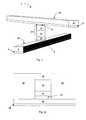
- FIGS. 2 a - 2 dare cross-sectional views illustrating fabrication of an embodiment of a memory cell according to the present invention.
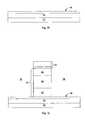
- FIGS. 3 a - 3 care cross-sectional views illustrating fabrication of a different embodiment of a memory cell according to the present invention.
- Such an antifuse-diode memory cellis in an unprogrammed state before the antifuse layer is ruptured and is in a programmed state after antifuse rupture.
- the antifuse layerelectrically separates the diode from an adjacent conductor. Performance of such cells is strongly influenced by the characteristics of the antifuse layer and its adjacent layers. Ideally there is very little leakage current across the antifuse layer before it is ruptured, and high current after. Unintentional rupture of the antifuse layer, which may occur when a cell is being read or when a neighboring cell is written, is also to be avoided.
- Use of different materials, dopant concentrations, thicknesses of layers, etc.affect the leakage current, programmed current, and tendency of the cell to be unintentionally programmed.
- the memory cell 2is unprogrammed when antifuse layer 16 is intact. To program the cell, a voltage sufficient to cause breakdown of the antifuse material is applied across antifuse layer 16 . It is advantageous to maximize the difference in current between an unprogrammed cell and a programmed cell and to improve uniformity between cells. The present invention minimizes the distribution of forward current values after programming of such a cell, improving reliability of the memory array.
- contact-antifuse unitwith a vertically oriented junction diode.
- the term contact-antifuse unitwill be used herein to describe a silicide layer with a dielectric antifuse layer formed on and in contact with it.
- the contact-antifuse unitmay contain other layers in addition to the silicide layer and the dielectric antifuse layer, and may be placed either above or below the vertically oriented junction diode.
- the application Ser. No. 10/727,765 of Herner(attorney docket number MA-070-1), filed on even date herewith, describes use of silicon oxide, silicon nitride, and silicon oxynitride dielectrics grown on the selected silicides. Any of these methods can advantageously be used to form the antifuse layer of the contact-antifuse unit of the present invention.
- a contact-antifuse unitcomprising a silicide and a dielectric antifuse layer is formed above a vertically oriented junction diode.
- Formation of a memory levelbegins as in the '470 application: Layers of titanium nitride 24 and tungsten 26 are deposited, then patterned and etched to form substantially parallel conductors, shown extending across the page. Dielectric fill (not shown) is deposited between and over the conductors, then planarized, for example by chemical-mechanical polishing (CMP) to expose the tungsten 26 of the conductors.
- CMPchemical-mechanical polishing
- a barrier layer 28preferably 200 angstroms of titanium nitride, is optionally deposited on the planarized conductors and fill.
- polycrystalline siliconherein referred to as polysilicon
- siliconcan either be deposited in polycrystalline form or deposited amorphous and crystallized later, for example by subsequent thermal processing.
- a first layer 32 of about 400 angstroms of in-situ doped polysilicon doped with boronis deposited to form a p-type polysilicon layer. This first layer 32 is preferably heavily doped, i.e.
- Gaps between the patterned pillarsare filled with dielectric fill 38 , then the fill is planarized, for example by CMP, to expose polysilicon.
- Ion implantation with an n-type dopant, for example phosphorusis performed to dope a top region 36 of the pillar.
- a middle region of the pillar 34below the n-doped region at the top, remains lightly doped or undoped.
- about 2900 angstroms of undoped polysilicon region 34is deposited, followed by about 1400 angstroms of in-situ doped polysilicon region 36 doped with an n-type dopant, for example phosphorus.
- the resulting structureis shown in FIG. 2 a.
- junction diodehaving a first, bottom electrode of p-type material and a second, top electrode of n-type material was described.
- the inverted diodewith the n-type electrode at the bottom and the p-type electrode at the top at the top, could have been used instead.
- cobalt 42is deposited on the dielectric 38 and exposed pillars.
- Cobaltcan be deposited by any conventional method, for example by sputtering.
- Other metalscan be used in place of cobalt, including chromium, nickel, platinum, niobium, palladium, tantalum, or titanium. For simplicity, this description will detail the use of cobalt, but it will be understood that any of these other metals can be substituted as appropriate.
- the titanium or titanium nitride capassists in the subsequent conversion of the cobalt layer to cobalt silicide.
- an annealis performed at a suitable temperature to react the cobalt with the polysilicon of the exposed diodes to form cobalt silicide 44 on the diodes only; no silicide is formed where the cobalt overlies oxide fill 38 .
- the annealmay be performed in a rapid thermal annealing system at about 400 to about 700 degrees C. for about 20 to about 100 seconds, preferably at about 500 degrees C. for about 30 seconds.
- the capping layer and unreacted portions of the cobaltare removed by a selective etch. Any etching medium which selectively etches the capping layer and the unreacted cobalt while leaving cobalt silicide may be used. Preferably, selective wet etching is used.
- a second annealis performed to homogenize the cobalt silicide 44 to CoSi 2 .
- This annealis performed at a temperature from about 650 degrees C. to about 850 degrees C. for about 10 to about 60 seconds, preferably at about 750 degrees C. for about 30 seconds.
- This second annealcan be performed at any time after the first.
- a single annealis performed after all of the memory levels are constructed to homogenize the cobalt silicide.
- the second annealcan be combined with antifuse growth.
- a dielectric layer 46is grown on the cobalt silicide 44 .
- silicon oxideis grown by exposing the silicide layer 44 to an oxygen atmosphere in a rapid thermal annealing system, preferably at about 670 to about 750 degrees C. for about 20 to about 60 seconds. If the second anneal to homogenize cobalt silicide is to be performed in the same thermal process as antifuse growth, this step can be performed at about 600 to about 850 degrees C, preferably at about 750 degrees C., for about 20 to about 300 seconds, preferably about 120 seconds.
- the resulting oxideis preferably between about 25 and about 200 angstroms thick, more preferably between about 100 and 150 angstroms thick, most preferably about 150 angstroms thick.
- a silicon nitride layercan be grown, for example by flowing 4 liters/minute of NH 3 at 750 degrees for 60 seconds at atmospheric pressure; the ramp rate is 50 degrees/second.
- Alternate source gases that may be usedare NO and N 2 O, as taught in the Herner application filed on even date herewith Ser. No. 10/727,765.
- a silicon oxynitride layercan be grown by exposing a silicide to an oxygen- and nitrogen-containing ambient, or, for example, by exposing a silicide to oxygen- and nitrogen-containing ambients in sequence, i.e. nitriding a grown oxide or oxidizing a grown nitride; these methods are also taught in the same application.
- Silicon nitride or silicon oxynitridecan be grown on cobalt silicide, nickel silicide, platinum silicide, palladium silicide, niobium silicide, tantalum silicide, or chromium silicide.
- the silicon oxide antifuse layerpreferably comprises stoichiometric silicon dioxide, but also may include a non-stoichiometric silicon oxide layer (i.e., a layer having a silicon to oxygen ratio of other than 1:2.) Similarly, silicon nitride may or may not be stoichiometric Si 3 N 4 .
- titaniumwas deposited in place of cobalt and titanium silicide was formed in place of cobalt silicide layer 44 , exposure to an oxygen atmosphere at about 700 degrees C. for about 30 seconds will form thermally grown titanium oxide on the titanium silicide.
- the titanium oxidecan replace the silicon oxide, silicon nitride, or silicon oxynitride of the antifuse layer 46 .
- a dielectric antifuse layercan be deposited rather than grown on the silicide layer 44 .
- this layercan be deposited by atomic layer deposition, or by some other chemical vapor deposition (CVD) process.
- an adhesion layer 48is deposited, preferably 200 angstroms of conductive material, preferably titanium nitride. Tantalum nitride, tungsten nitride, tantalum, or titanium tungsten can be substituted for titanium nitride.
- a titanium nitride layer deposited immediately over the silicon oxide antifusemay be deposited using a physical vapor deposition (PVD) process without applied self-bias; a PVD process is typically performed at about 0.5 to about 5 mTorr.
- PVDphysical vapor deposition
- This techniqueis used, rather than a self-biased PVD process, to avoid damaging the fragile silicon dioxide antifuse layer.
- This deposition methodmay optionally be employed for this layer.
- the resulting layer of titanium nitridewill have lower density and higher resistivity than conventionally formed titanium nitride, and will decrease leakage current across the antifuse before antifuse rupture. Formation and use of this low-density, high-resistivity titanium nitride is described in Herner, U.S. patent application Ser. No. 10/611,245, “Low Density, High Resistivity Titanium Nitride Layer for Use as a Contact for Low-Leakage Dielectric Layers,” filed Jun. 30, 2003, hereinafter the '245 application, hereby incorporated by reference.
- tungsten 50is deposited on the titanium nitride layer, then the tungsten and titanium nitride layers are patterned and etched to form substantially parallel evenly spaced second conductors.
- the second conductorsare preferably substantially perpendicular to the first conductors.
- the junction diodeis preferably aligned at the intersection of the first conductor below it and the second conductor above it, but some misalignment can be tolerated.
- the antifuse layeris preferably silicon oxide, silicon nitride, or silicon oxynitride, and is preferably grown, preferably thermally grown, on the silicide.
- the silicide of the contact-antifuse unitis in contact with an electrode of the junction diode.
- the contact-antifuse unitfurther comprises a layer above the antifuse layer which is titanium nitride, tantalum nitride, tungsten nitride, tantalum, or titanium tungsten.
- the junction diode and contact-antifuse unitare portions of a memory cell, which is part of a memory array.
- the memory arraymay be a portion of a monolithic three dimensional memory array.
- a contact-antifuse unitcomprising a silicide and a dielectric antifuse layer is formed below a vertically oriented junction diode.
- the first titanium nitride-tungsten conductors of the '470 applicationare replaced with silicon lines 52 , shown in FIG. 3 a.
- a layer of amorphous silicon or polysiliconpreferably about 1500-2500 angstroms thick, most preferably about 2500 angstroms thick, which may be undoped or may be doped with n-type or p-type dopants, is deposited. N-type doped amorphous silicon is preferred.
- This silicon layerwill typically be amorphous as deposited, but will become polycrystalline during subsequent thermal processing.
- the silicon layeris patterned and etched to form a plurality of substantially parallel lines.
- the gaps between the linesare filled with dielectric fill (not shown), preferably silicon dioxide.
- the gap fillis planarized, preferably by CMP, to expose the silicon lines.
- silicon linescan be formed in the surface of a monocrystalline wafer by etching trenches and filling them with a dielectric using conventional techniques.
- the silicon lines 52can be formed in the surface of a silicon on insulator substrate or a layer of epitaxially grown silicon.
- cobaltAfter an optional 50 angstrom pre-sputter etch to remove any native oxide or particle defects, about 20 to about 500 angstroms, preferably about 300 to 400 angstroms, most preferably about 300 angstroms of cobalt is deposited on the dielectric and exposed silicon lines 52 .
- the preferred thickness of the cobalt layeris thicker in this embodiment than in the previous embodiment because the resulting cobalt silicide layer will serve as wiring within the array.
- a layer of cobalt 54can be deposited by any conventional method, for example by sputtering.
- Other metalscan be used in place of the cobalt, including chromium, nickel, platinum, niobium, palladium, tantalum, or titanium. For simplicity, this description will detail the use of cobalt, but it will be understood that any of these other metals can be substituted as appropriate.
- the titanium or titanium nitride capassists in the subsequent conversion of the cobalt layer to cobalt silicide.
- An annealis performed at a suitable temperature to react the cobalt with the polysilicon of the exposed silicon lines to form cobalt silicide 56 on the silicon lines 52 , shown in FIG. 3 b.
- the annealmay be performed in a rapid thermal annealing system at about 400 to about 700 degrees C. for about 20 to about 100 seconds, preferably at about 500 degrees C. for about 30 seconds.
- the capping layer and unreacted portions of the cobaltare removed by a selective etch. Any etching medium which selectively etches the capping layer and the unreacted cobalt while leaving cobalt silicide 56 may be used.
- selective wet etchingis used.
- a second annealis performed to homogenize the cobalt silicide 56 to CoSi 2 .
- This annealis performed at a temperature from about 550 degrees C. to about 800 degrees C. for about 30 to about 60 seconds, preferably at about 740 degrees C. for about 30 seconds.
- This second annealcan be performed at any time after the first.
- a single annealis performed after all of the memory levels are constructed to homogenize the cobalt silicide.
- the second annealcan be combined with antifuse growth.
- a dielectric layer 58is thermally grown on the cobalt silicide 56 .
- silicon oxideis grown by exposing the silicide layer 56 to an oxygen atmosphere in a rapid thermal annealing system, preferably at about 670 to about 750 degrees C. for about 20 to about 60 seconds. If the second anneal to homogenize cobalt silicide is to be performed in the same thermal process as antifuse growth, this step can be performed at about 600 to about 850 degrees C., preferably at about 750 degrees C., for about 20 to about 300 seconds, preferably about 120 seconds. Other methods may be used, including as any of those taught in the '962 application.
- Silicon oxidecan be grown on cobalt silicide, nickel silicide, platinum silicide, palladium silicide, tantalum silicide or chromium silicide. As will be described below, a thin layer of titanium nitride may be deposited next. The preferred thickness of the antifuse (and thus the conditions used to produce it) varies according to whether or not this layer is present.
- a silicon nitride layercan be grown, for example by flowing 4 liters/minute of NH 3 at 750 degrees for 60 seconds at atmospheric pressure; the ramp rate is 50 degrees/second.
- Alternate source gases that may be usedare NO and N 2 O, as taught in the Herner application filed on even date herewith.
- a silicon oxynitride layercan be grown by exposing a silicide to an oxygen- and nitrogen-containing ambient, or, for example, by exposing a silicide to oxygen- and nitrogen-containing ambients in sequence, i.e. nitriding a grown oxide or oxidizing a grown nitride; these methods are also taught in the same application.
- the silicon oxide antifuse layerpreferably comprises stoichiometric silicon dioxide, but also may include a non-stoichiometric silicon oxide layer (i.e., a layer having a silicon to oxygen ratio of other than 1:2.) Similarly, silicon nitride may or may not be stoichiometric Si 3 N 4 .
- the overlying junction diode 60proceeds as in the '470 application and as in the earlier description of the contact-antifuse unit formed above the junction diode.
- layer 62is a heavily doped layer of a first conductivity type
- layer 64is an undoped layer or a lightly doped layer of a second conductivity type
- layer 66is a heavily doped layer of the second conductivity type.
- the polysilicon layers that will form the junction diodeare deposited, patterned, and etched to form pillars, and the gaps between the pillars are filled with dielectric fill 38 , preferably silicon dioxide.
- dielectric fill 38preferably silicon dioxide.
- Another semiconductor materialfor example silicon-germanium or germanium, could replace the silicon forming this junction diode.
- dielectric antifuse layer 58It may be desirable, after formation of dielectric antifuse layer 58 and before deposition of the polysilicon that will form the junction diode 60 , to deposit a thin layer of conductive material, preferably titanium nitride, tantalum nitride, tungsten nitride, tantalum, or titanium tungsten (not shown.) It may be advantageous to use the low-density, high-resistivity titanium nitride (or tantalum nitride, tungsten nitride, tantalum, or titanium tungsten) described in the '245 application employed for this layer. The resulting layer of titanium nitride will have lower density and higher resistivity than conventionally formed titanium nitride, and will decrease leakage current across the antifuse before antifuse rupture.
- conductive materialpreferably titanium nitride, tantalum nitride, tungsten nitride, tantalum, or titanium tungsten (not
- overlying conductorsproceeds as in the '470 application, and as in the earlier description of the contact-antifuse unit formed above the junction diode. Since, in the present embodiment, no antifuse is formed at the top of the junction diode, a self-biased PVD process can be used if preferred to form titanium nitride at the bottom of the overlying conductors.
- a silicidefor example titanium silicide or cobalt silicide can be formed prior to or at the same time as the formation of the overlying conductors.
- the structure at this point, including junction diode 60 , which is surrounded by dielectric fill 38 , and overlying conductor 62is shown in FIG. 3 c. (Recall that overlying conductor 62 is substantially perpendicular to silicon line 52 and cobalt silicide 56 and is thus shown here in cross section.) ⁇
- the resulting structureincludes a vertically oriented junction diode.
- This junction diodecan be a p-n diode or a p-i-n diode, with the p-type electrode at the bottom and the n-type electrode at the top or vice versa.
- Below and in contact with an electrode of the junction diodeis a contact-antifuse unit.
- the contact-antifuse unitcomprises a silicide and an antifuse layer formed on the silicide.
- the antifuse layeris preferably silicon oxide, silicon nitride, or silicon oxynitride, and is preferably grown, preferably thermally grown on the silicide.
- the contact-antifuse unitoptionally further comprises a layer above the antifuse layer which is a conductive material, for example titanium nitride, tantalum nitride, tungsten nitride, tantalum, or titanium tungsten. If this optional layer of conductive material is present, it is in contact with an electrode of the junction diode. If it is absent, the antifuse is on contact with an electrode of the junction diode.
- the junction diode and contact-antifuse unitare portions of a memory cell, which is part of a memory array.
- the memory arraymay be a portion of a monolithic three dimensional memory array.
- the dielectric antifuse of the contact-antifuse unit of the present inventionpreferably includes a grown dielectric, such as an oxide.
- a grown oxideis one formed by converting a portion of the underlying silicide/silicon film stack to silicon oxide by exposing the silicide layer to an oxygen-containing ambient.
- silicon from the underlying silicon layer in the stackdiffuses through the cobalt silicide layer to react with the oxygen-containing ambient to form a layer which substantially comprises silicon oxide.
- a relatively thin dielectricis to be grown on a silicide which is not formed on an underlying silicon layer, it is believed that silicon can be depleted from the silicide, leaving a relatively silicon-poor silicide.
- a grown silicon nitrideis formed by exposing the silicide to a nitrogen-containing ambient, while a grown silicon oxynitride is grown, for example, by exposing the silicide to an oxygen- and nitrogen-containing ambient.
- a deposited silicon nitride layeris formed on a surface by providing silicon and nitrogen atoms to the surface; a deposited silicon oxynitride layer is formed by providing silicon, oxygen, and nitrogen atoms to the surface.
- a grown dielectricrefers to a dielectric grown as per the preceding descriptions, such as grown silicon oxide, grown silicon nitride, or grown silicon oxynitride.
- a grown dielectricsuch as the silicon oxide, silicon nitride, or silicon oxynitride described earlier, is generally measurably different from a deposited oxide of the same material.
- the grown dielectric layerhas fewer defects and is generally denser than a corresponding deposited dielectric and forms a higher quality antifuse. Further, a grown dielectric can reliably be produced thinner than can a corresponding deposited dielectric. Dielectrics can of 50 angstroms or less, for example, can be grown, while it is very difficult or impossible to reliably deposit a dielectric layer this thin.
- a grown dielectricis also preferable in that processing to produce it is simpler and less costly than for a deposited dielectric.
- junction diodes and contact-antifuse unit combinationsi.e., contact-antifuse unit above or below the junction diode
- contact-antifuse unit combinationsi.e., contact-antifuse unit above or below the junction diode
- either or bothcan be combined in a memory array with the diode-antifuse memory cells of the '470 application which do not include a silicide layer.
- memory cells according to the present inventionare advantageously used in a monolithic three dimensional memory array in which multiple memory levels are formed, the levels formed above a substrate and stacked vertically one above the other.
- Preferred embodiments having the contact-antifuse unit below the junction diodehave the first level junction diode disposed between first silicon lines with cobalt silicide on them (these lines below the first level junction diode), and second conductors comprising titanium nitride and tungsten (these conductors formed above the first level junction diode.)
- a second memory levelis typically formed above this first level.
- the second level junction diodes formed above the second conductors, in the second memory levelare the diodes described in the '470 application, which have an antifuse grown on silicon at the top of the diode and which do not include a silicide layer.
- the second level diodesmay be upside-down relative to the first level diodes; i.e.
- a dielectric layercovers the two memory levels formed so far, and is planarized. Construction of more memory levels, not sharing conductors with the two existing memory levels, begins anew atop this interlevel dielectric. Two more memory levels identical to the first two can then be fabricated, or memory levels employing other cells can be fabricated instead.
- a monolithic three dimensional memory arrayis one in which multiple memory levels are formed above a single substrate, such as a wafer, with no intervening substrates.
- stacked memorieshave been constructed by forming memory levels on separate substrates and adhering the memory levels atop each other, as in Leedy, U.S. Pat. No. 5,915,167, “Three dimensional structure memory.” The substrates may be thinned or removed from the memory levels before bonding, but as the memory levels are initially formed over separate substrates, such memories are not true monolithic three dimensional memory arrays.
- junction diode and a contact-antifuse unitcomprising a silicide and a dielectric antifuse layer
- a monolithic three dimensional memory arrayformed above a substrate.
- Such an arraycomprises at least a first memory level formed at a first height above the substrate and a second memory level formed at a second height different from the first height.
- Three, four, eight, or more memory levelscan be formed above the substrate in such a multilevel array.
Landscapes
- Physics & Mathematics (AREA)
- Condensed Matter Physics & Semiconductors (AREA)
- General Physics & Mathematics (AREA)
- Engineering & Computer Science (AREA)
- Computer Hardware Design (AREA)
- Microelectronics & Electronic Packaging (AREA)
- Power Engineering (AREA)
- Semiconductor Memories (AREA)
- Design And Manufacture Of Integrated Circuits (AREA)
Abstract
Description
Claims (85)
Priority Applications (11)
| Application Number | Priority Date | Filing Date | Title |
|---|---|---|---|
| US10/728,230US6946719B2 (en) | 2003-12-03 | 2003-12-03 | Semiconductor device including junction diode contacting contact-antifuse unit comprising silicide |
| US10/954,510US7176064B2 (en) | 2003-12-03 | 2004-09-29 | Memory cell comprising a semiconductor junction diode crystallized adjacent to a silicide |
| US11/560,289US8018024B2 (en) | 2003-12-03 | 2006-11-15 | P-i-n diode crystallized adjacent to a silicide in series with a dielectric antifuse |
| US11/560,283US7682920B2 (en) | 2003-12-03 | 2006-11-15 | Method for making a p-i-n diode crystallized adjacent to a silicide in series with a dielectric antifuse |
| US11/613,151US7833843B2 (en) | 2003-12-03 | 2006-12-19 | Method for forming a memory cell comprising a semiconductor junction diode crystallized adjacent to a silicide |
| US11/693,858US20070164388A1 (en) | 2002-12-19 | 2007-03-30 | Memory cell comprising a diode fabricated in a low resistivity, programmed state |
| US11/693,845US7618850B2 (en) | 2002-12-19 | 2007-03-30 | Method of making a diode read/write memory cell in a programmed state |
| US12/588,088US7915094B2 (en) | 2002-12-19 | 2009-10-02 | Method of making a diode read/write memory cell in a programmed state |
| US12/698,253US8003477B2 (en) | 2003-12-03 | 2010-02-02 | Method for making a P-I-N diode crystallized adjacent to a silicide in series with a dielectric antifuse |
| US13/229,747US8330250B2 (en) | 2003-12-03 | 2011-09-11 | P-I-N diode crystallized adjacent to a silicide in series with a dielectric material |
| US13/705,227US8633567B2 (en) | 2003-12-03 | 2012-12-05 | Devices including a P-I-N diode disposed adjacent a silicide in series with a dielectric material |
Applications Claiming Priority (1)
| Application Number | Priority Date | Filing Date | Title |
|---|---|---|---|
| US10/728,230US6946719B2 (en) | 2003-12-03 | 2003-12-03 | Semiconductor device including junction diode contacting contact-antifuse unit comprising silicide |
Related Child Applications (3)
| Application Number | Title | Priority Date | Filing Date |
|---|---|---|---|
| US10/954,510Continuation-In-PartUS7176064B2 (en) | 2002-12-19 | 2004-09-29 | Memory cell comprising a semiconductor junction diode crystallized adjacent to a silicide |
| US11/560,283Continuation-In-PartUS7682920B2 (en) | 2003-12-03 | 2006-11-15 | Method for making a p-i-n diode crystallized adjacent to a silicide in series with a dielectric antifuse |
| US11/560,289Continuation-In-PartUS8018024B2 (en) | 2003-12-03 | 2006-11-15 | P-i-n diode crystallized adjacent to a silicide in series with a dielectric antifuse |
Publications (2)
| Publication Number | Publication Date |
|---|---|
| US20050121742A1 US20050121742A1 (en) | 2005-06-09 |
| US6946719B2true US6946719B2 (en) | 2005-09-20 |
Family
ID=34633662
Family Applications (1)
| Application Number | Title | Priority Date | Filing Date |
|---|---|---|---|
| US10/728,230Expired - LifetimeUS6946719B2 (en) | 2002-12-19 | 2003-12-03 | Semiconductor device including junction diode contacting contact-antifuse unit comprising silicide |
Country Status (1)
| Country | Link |
|---|---|
| US (1) | US6946719B2 (en) |
Cited By (136)
| Publication number | Priority date | Publication date | Assignee | Title |
|---|---|---|---|---|
| US20050052915A1 (en)* | 2002-12-19 | 2005-03-10 | Matrix Semiconductor, Inc. | Nonvolatile memory cell without a dielectric antifuse having high- and low-impedance states |
| US20050226067A1 (en)* | 2002-12-19 | 2005-10-13 | Matrix Semiconductor, Inc. | Nonvolatile memory cell operating by increasing order in polycrystalline semiconductor material |
| US20050242386A1 (en)* | 2004-04-29 | 2005-11-03 | Kern-Huat Ang | Memory cell and method of fabricating the same |
| US20060067117A1 (en)* | 2004-09-29 | 2006-03-30 | Matrix Semiconductor, Inc. | Fuse memory cell comprising a diode, the diode serving as the fuse element |
| US20060189077A1 (en)* | 2002-12-19 | 2006-08-24 | Sandisk 3D Llc | Method for making high-density nonvolatile memory |
| US20060250837A1 (en)* | 2005-05-09 | 2006-11-09 | Sandisk 3D, Llc | Nonvolatile memory cell comprising a diode and a resistance-switching material |
| US20070072360A1 (en)* | 2005-09-28 | 2007-03-29 | Tanmay Kumar | Method for using a memory cell comprising switchable semiconductor memory element with trimmable resistance |
| US20070069217A1 (en)* | 2003-12-03 | 2007-03-29 | Herner S B | P-i-n diode crystallized adjacent to a silicide in series with a dielectric anitfuse |
| US20070087508A1 (en)* | 2003-12-03 | 2007-04-19 | Herner S B | Method for making a p-i-n diode crystallized adjacent to a silicide in series with a dielectric antifuse |
| US20070105284A1 (en)* | 2003-12-03 | 2007-05-10 | Herner S B | Method for forming a memory cell comprising a semiconductor junction diode crystallized adjacent to a silicide |
| US20070114508A1 (en)* | 2005-11-23 | 2007-05-24 | Matrix Semiconductor, Inc. | Reversible resistivity-switching metal oxide or nitride layer with added metal |
| US20070114509A1 (en)* | 2005-11-23 | 2007-05-24 | Sandisk 3D Llc | Memory cell comprising nickel-cobalt oxide switching element |
| US20070164388A1 (en)* | 2002-12-19 | 2007-07-19 | Sandisk 3D Llc | Memory cell comprising a diode fabricated in a low resistivity, programmed state |
| US20070164309A1 (en)* | 2002-12-19 | 2007-07-19 | Sandisk 3D Llc | Method of making a diode read/write memory cell in a programmed state |
| US20070190722A1 (en)* | 2002-12-19 | 2007-08-16 | Herner S B | Method to form upward pointing p-i-n diodes having large and uniform current |
| US20070228414A1 (en)* | 2006-03-31 | 2007-10-04 | Sandisk 3D, Llc | Heterojunction device comprising a semiconductor and a resistivity-switching oxide or nitride |
| US20070228354A1 (en)* | 2006-03-31 | 2007-10-04 | Sandisk 3D, Llc | Nonvolatile rewritable memory cell comprising a resistivity-switching oxide or nitride and an antifuse |
| US20070236981A1 (en)* | 2006-03-31 | 2007-10-11 | Sandisk 3D, Llc | Multilevel nonvolatile memory cell comprising a resistivity-switching oxide or nitride and an antifuse |
| US20080007989A1 (en)* | 2005-09-28 | 2008-01-10 | Sandisk 3D Llc | Programming methods to increase window for reverse write 3D cell |
| US20080013355A1 (en)* | 2003-12-18 | 2008-01-17 | Herner S B | Selective oxidation of silicon in diode, tft and monolithic three dimensional memory arrays |
| US20080013364A1 (en)* | 2002-12-19 | 2008-01-17 | Sandisk 3D Llc | Method of making non-volatile memory cell with embedded antifuse |
| US20080017912A1 (en)* | 2002-12-19 | 2008-01-24 | Sandisk 3D Llc | Non-volatile memory cell with embedded antifuse |
| US20080179685A1 (en)* | 2007-01-31 | 2008-07-31 | Petti Christopher J | Embedded memory in a cmos circuit and methods of forming the same |
| US20080182367A1 (en)* | 2007-01-31 | 2008-07-31 | Petti Christopher J | Embedded memory in a cmos circuit and methods of forming the same |
| US20080242080A1 (en)* | 2007-03-30 | 2008-10-02 | Sandisk 3D Llc | Method for implementing diffusion barrier in 3D memory |
| US20080237862A1 (en)* | 2007-03-30 | 2008-10-02 | Sandisk 3D Llc | Implementation of diffusion barrier in 3D memory |
| US20080237599A1 (en)* | 2007-03-27 | 2008-10-02 | Herner S Brad | Memory cell comprising a carbon nanotube fabric element and a steering element |
| US20080239790A1 (en)* | 2007-03-27 | 2008-10-02 | Herner S Brad | Method to form a memory cell comprising a carbon nanotube fabric element and a steering element |
| US20080239787A1 (en)* | 2007-03-27 | 2008-10-02 | Herner S Brad | Large array of upward pointing p-i-n diodes having large and uniform current |
| WO2008121674A1 (en)* | 2007-03-30 | 2008-10-09 | Sandisk 3D Llc | Diffusion barrier in 3d memory and method for implementing |
| US20080254615A1 (en)* | 2005-03-25 | 2008-10-16 | Dunton Samuel V | Method for reducing dielectric overetch using a dielectric etch stop at a planar surface |
| US20080308903A1 (en)* | 2007-06-15 | 2008-12-18 | Sandisk 3D Llc | Polycrystalline thin film bipolar transistors |
| US20080311722A1 (en)* | 2007-06-15 | 2008-12-18 | Sandisk 3D Llc | Method for forming polycrystalline thin film bipolar transistors |
| US20080311710A1 (en)* | 2007-06-15 | 2008-12-18 | Herner S Brad | Method to form low-defect polycrystalline semiconductor material for use in a transistor |
| US20080316795A1 (en)* | 2007-06-25 | 2008-12-25 | Sandisk 3D Llc | Method of making nonvolatile memory device containing carbon or nitrogen doped diode |
| US20080316809A1 (en)* | 2007-06-25 | 2008-12-25 | Sandisk 3D Llc | High forward current diodes for reverse write 3D cell |
| US20080316796A1 (en)* | 2007-06-25 | 2008-12-25 | Sandisk 3D Llc | Method of making high forward current diodes for reverse write 3D cell |
| US20080316808A1 (en)* | 2007-06-25 | 2008-12-25 | Sandisk 3D Llc | Nonvolatile memory device containing carbon or nitrogen doped diode |
| US20090001342A1 (en)* | 2007-06-29 | 2009-01-01 | April Schricker | Memory cell that employs a selectively grown reversible resistance-switching element and methods of forming the same |
| US20090004786A1 (en)* | 2007-06-27 | 2009-01-01 | Radigan Steven J | Method for fabricating a 3-d integrated circuit using a hard mask of silicon-oxynitride on amorphous carbon |
| US20090001343A1 (en)* | 2007-06-29 | 2009-01-01 | April Schricker | Memory cell that employs a selectively deposited reversible resistance-switching element and methods of forming the same |
| US20090001344A1 (en)* | 2007-06-29 | 2009-01-01 | April Schricker | Memory cell that employs a selectively grown reversible resistance-switching element and methods of forming the same |
| US20090003036A1 (en)* | 2007-06-29 | 2009-01-01 | Sandisk 3D Llc | Method of making 3D R/W cell with reduced reverse leakage |
| US20090001347A1 (en)* | 2007-06-29 | 2009-01-01 | Sandisk 3D Llc | 3D R/W cell with reduced reverse leakage |
| US20090001345A1 (en)* | 2007-06-29 | 2009-01-01 | April Schricker | Memory cell that employs a selectively deposited reversible resistance-switching element and methods of forming the same |
| WO2009005706A3 (en)* | 2007-06-29 | 2009-03-19 | Sandisk 3D Llc | Method to form a rewriteable memory cell comprising a diode and a resistivity-switching grown oxide |
| US20090085154A1 (en)* | 2007-09-28 | 2009-04-02 | Herner S Brad | Vertical diode based memory cells having a lowered programming voltage and methods of forming the same |
| US20090142921A1 (en)* | 2005-03-25 | 2009-06-04 | Sandisk 3D Llc | Method for reducing dielectric overetch when making contact to conductive features |
| US20090152549A1 (en)* | 2007-12-14 | 2009-06-18 | Semiconductor Energy Laboratory Co., Ltd. | Memory device |
| US20090166609A1 (en)* | 2007-12-31 | 2009-07-02 | April Schricker | Memory cell that employs a selectively fabricated carbon nano-tube reversible resistance-switching element formed over a bottom conductor and methods of forming the same |
| US20090166610A1 (en)* | 2007-12-31 | 2009-07-02 | April Schricker | Memory cell with planarized carbon nanotube layer and methods of forming the same |
| US20090224244A1 (en)* | 2005-02-17 | 2009-09-10 | Sandisk 3D Llc | Patterning of submicron pillars in a memory array |
| US20090257265A1 (en)* | 2008-04-11 | 2009-10-15 | Sandisk 3D Llc | Multilevel nonvolatile memory device containing a carbon storage material and methods of making and using same |
| US20090256130A1 (en)* | 2008-04-11 | 2009-10-15 | Sandisk 3D Llc | Memory cell that employs a selectively fabricated carbon nano-tube reversible resistance-switching element, and methods of forming the same |
| US20090258318A1 (en)* | 2008-04-11 | 2009-10-15 | Sandisk 3D Llc | Double patterning method |
| US20090256129A1 (en)* | 2008-04-11 | 2009-10-15 | Sandisk 3D Llc | Sidewall structured switchable resistor cell |
| US20090258501A1 (en)* | 2008-04-11 | 2009-10-15 | Sandisk 3D Llc | Double patterning method |
| US20090256131A1 (en)* | 2008-04-11 | 2009-10-15 | Sandisk 3D Llc | Memory cell that employs a selectively fabricated carbon nano-tube reversible resistance-switching element formed over a bottom conductor and methods of forming the same |
| US20090258495A1 (en)* | 2008-04-11 | 2009-10-15 | Sandisk 3D Llc | Modified darc stack for resist patterning |
| US20090268508A1 (en)* | 2008-04-29 | 2009-10-29 | Sandisk 3D Llc | Reverse leakage reduction and vertical height shrinking of diode with halo doping |
| US20100032732A1 (en)* | 2008-08-06 | 2010-02-11 | International Business Machines Corporation | Electrical antifuse having a multi-thickness dielectric layer |
| US20100078618A1 (en)* | 2008-09-30 | 2010-04-01 | Sandisk 3D Llc | Self-assembly process for memory array |
| US20100086875A1 (en)* | 2008-10-06 | 2010-04-08 | Sandisk 3D Llc | Method of making sub-resolution pillar structures using undercutting technique |
| US20100105210A1 (en)* | 2008-10-27 | 2010-04-29 | Sandisk 3D Llc | Method of making pillars using photoresist spacer mask |
| US7732235B2 (en) | 2008-06-30 | 2010-06-08 | Sandisk 3D Llc | Method for fabricating high density pillar structures by double patterning using positive photoresist |
| US20100163831A1 (en)* | 2004-09-29 | 2010-07-01 | Sandisk 3D Llc | Deposited semiconductor structure to minimize n-type dopant diffusion and method of making |
| US20100167520A1 (en)* | 2008-12-31 | 2010-07-01 | Sandisk 3D Llc | Resist feature and removable spacer pitch doubling patterning method for pillar structures |
| US20100167502A1 (en)* | 2008-12-31 | 2010-07-01 | Sandisk 3D Llc | Nanoimprint enhanced resist spacer patterning method |
| US20100181657A1 (en)* | 2002-12-19 | 2010-07-22 | Sandisk 3D Llc | Nonvolatile memory cell comprising a reduced height vertical diode |
| US20100193916A1 (en)* | 2008-12-31 | 2010-08-05 | Sandisk 3D Llc | Methods for increased array feature density |
| US7800932B2 (en) | 2005-09-28 | 2010-09-21 | Sandisk 3D Llc | Memory cell comprising switchable semiconductor memory element with trimmable resistance |
| US20100276660A1 (en)* | 2005-07-01 | 2010-11-04 | Xiaoyu Yang | Memory with high dielectric constant antifuses adapted for use at low voltage |
| US7846782B2 (en) | 2007-09-28 | 2010-12-07 | Sandisk 3D Llc | Diode array and method of making thereof |
| US7923305B1 (en) | 2010-01-12 | 2011-04-12 | Sandisk 3D Llc | Patterning method for high density pillar structures |
| US20110110149A1 (en)* | 2005-01-19 | 2011-05-12 | Scheuerlein Roy E | Structure and method for biasing phase change memory array for reliable writing |
| US20110171815A1 (en)* | 2010-01-12 | 2011-07-14 | Sandisk 3D Llc | Patterning method for high density pillar structures |
| US20120015506A1 (en)* | 2010-07-13 | 2012-01-19 | Crossbar, Inc. | Two terminal resistive switching device structure and method of fabricating |
| US8236623B2 (en) | 2007-12-31 | 2012-08-07 | Sandisk 3D Llc | Memory cell that employs a selectively fabricated carbon nano-tube reversible resistance-switching element and methods of forming the same |
| US8374018B2 (en) | 2010-07-09 | 2013-02-12 | Crossbar, Inc. | Resistive memory using SiGe material |
| US8391049B2 (en) | 2010-09-29 | 2013-03-05 | Crossbar, Inc. | Resistor structure for a non-volatile memory device and method |
| US8394670B2 (en) | 2011-05-31 | 2013-03-12 | Crossbar, Inc. | Vertical diodes for non-volatile memory device |
| US8404553B2 (en) | 2010-08-23 | 2013-03-26 | Crossbar, Inc. | Disturb-resistant non-volatile memory device and method |
| US8441835B2 (en) | 2010-06-11 | 2013-05-14 | Crossbar, Inc. | Interface control for improved switching in RRAM |
| US8450710B2 (en) | 2011-05-27 | 2013-05-28 | Crossbar, Inc. | Low temperature p+ silicon junction material for a non-volatile memory device |
| US8450209B2 (en) | 2010-11-05 | 2013-05-28 | Crossbar, Inc. | p+ Polysilicon material on aluminum for non-volatile memory device and method |
| US8467227B1 (en) | 2010-11-04 | 2013-06-18 | Crossbar, Inc. | Hetero resistive switching material layer in RRAM device and method |
| US8492195B2 (en) | 2010-08-23 | 2013-07-23 | Crossbar, Inc. | Method for forming stackable non-volatile resistive switching memory devices |
| US8519485B2 (en) | 2010-06-11 | 2013-08-27 | Crossbar, Inc. | Pillar structure for memory device and method |
| US8558212B2 (en) | 2010-09-29 | 2013-10-15 | Crossbar, Inc. | Conductive path in switching material in a resistive random access memory device and control |
| US8658476B1 (en) | 2012-04-20 | 2014-02-25 | Crossbar, Inc. | Low temperature P+ polycrystalline silicon material for non-volatile memory device |
| US8659929B2 (en) | 2011-06-30 | 2014-02-25 | Crossbar, Inc. | Amorphous silicon RRAM with non-linear device and operation |
| US8716098B1 (en) | 2012-03-09 | 2014-05-06 | Crossbar, Inc. | Selective removal method and structure of silver in resistive switching device for a non-volatile memory device |
| US8765566B2 (en) | 2012-05-10 | 2014-07-01 | Crossbar, Inc. | Line and space architecture for a non-volatile memory device |
| US8791010B1 (en) | 2010-12-31 | 2014-07-29 | Crossbar, Inc. | Silver interconnects for stacked non-volatile memory device and method |
| US8796658B1 (en) | 2012-05-07 | 2014-08-05 | Crossbar, Inc. | Filamentary based non-volatile resistive memory device and method |
| US8809831B2 (en) | 2010-07-13 | 2014-08-19 | Crossbar, Inc. | On/off ratio for non-volatile memory device and method |
| US8815696B1 (en) | 2010-12-31 | 2014-08-26 | Crossbar, Inc. | Disturb-resistant non-volatile memory device using via-fill and etchback technique |
| US8878235B2 (en) | 2007-12-31 | 2014-11-04 | Sandisk 3D Llc | Memory cell that employs a selectively fabricated carbon nano-tube reversible resistance-switching element and methods of forming the same |
| US8884261B2 (en) | 2010-08-23 | 2014-11-11 | Crossbar, Inc. | Device switching using layered device structure |
| US8889521B1 (en) | 2012-09-14 | 2014-11-18 | Crossbar, Inc. | Method for silver deposition for a non-volatile memory device |
| US8930174B2 (en) | 2010-12-28 | 2015-01-06 | Crossbar, Inc. | Modeling technique for resistive random access memory (RRAM) cells |
| US8934280B1 (en) | 2013-02-06 | 2015-01-13 | Crossbar, Inc. | Capacitive discharge programming for two-terminal memory cells |
| US8947908B2 (en) | 2010-11-04 | 2015-02-03 | Crossbar, Inc. | Hetero-switching layer in a RRAM device and method |
| US8946669B1 (en) | 2012-04-05 | 2015-02-03 | Crossbar, Inc. | Resistive memory device and fabrication methods |
| US8946673B1 (en) | 2012-08-24 | 2015-02-03 | Crossbar, Inc. | Resistive switching device structure with improved data retention for non-volatile memory device and method |
| US8946046B1 (en) | 2012-05-02 | 2015-02-03 | Crossbar, Inc. | Guided path for forming a conductive filament in RRAM |
| US8982647B2 (en) | 2012-11-14 | 2015-03-17 | Crossbar, Inc. | Resistive random access memory equalization and sensing |
| US9087576B1 (en) | 2012-03-29 | 2015-07-21 | Crossbar, Inc. | Low temperature fabrication method for a three-dimensional memory device and structure |
| US9112145B1 (en) | 2013-01-31 | 2015-08-18 | Crossbar, Inc. | Rectified switching of two-terminal memory via real time filament formation |
| US9153623B1 (en) | 2010-12-31 | 2015-10-06 | Crossbar, Inc. | Thin film transistor steering element for a non-volatile memory device |
| US9191000B2 (en) | 2011-07-29 | 2015-11-17 | Crossbar, Inc. | Field programmable gate array utilizing two-terminal non-volatile memory |
| US9252191B2 (en) | 2011-07-22 | 2016-02-02 | Crossbar, Inc. | Seed layer for a p+ silicon germanium material for a non-volatile memory device and method |
| US9312483B2 (en) | 2012-09-24 | 2016-04-12 | Crossbar, Inc. | Electrode structure for a non-volatile memory device and method |
| US9324942B1 (en) | 2013-01-31 | 2016-04-26 | Crossbar, Inc. | Resistive memory cell with solid state diode |
| US9401475B1 (en) | 2010-08-23 | 2016-07-26 | Crossbar, Inc. | Method for silver deposition for a non-volatile memory device |
| US9406379B2 (en) | 2013-01-03 | 2016-08-02 | Crossbar, Inc. | Resistive random access memory with non-linear current-voltage relationship |
| US9412790B1 (en) | 2012-12-04 | 2016-08-09 | Crossbar, Inc. | Scalable RRAM device architecture for a non-volatile memory device and method |
| US9543359B2 (en) | 2011-05-31 | 2017-01-10 | Crossbar, Inc. | Switching device having a non-linear element |
| US9564587B1 (en) | 2011-06-30 | 2017-02-07 | Crossbar, Inc. | Three-dimensional two-terminal memory with enhanced electric field and segmented interconnects |
| US9570678B1 (en) | 2010-06-08 | 2017-02-14 | Crossbar, Inc. | Resistive RAM with preferental filament formation region and methods |
| US9576616B2 (en) | 2012-10-10 | 2017-02-21 | Crossbar, Inc. | Non-volatile memory with overwrite capability and low write amplification |
| US9583701B1 (en) | 2012-08-14 | 2017-02-28 | Crossbar, Inc. | Methods for fabricating resistive memory device switching material using ion implantation |
| USRE46335E1 (en) | 2010-11-04 | 2017-03-07 | Crossbar, Inc. | Switching device having a non-linear element |
| US9601692B1 (en) | 2010-07-13 | 2017-03-21 | Crossbar, Inc. | Hetero-switching layer in a RRAM device and method |
| US9601690B1 (en) | 2011-06-30 | 2017-03-21 | Crossbar, Inc. | Sub-oxide interface layer for two-terminal memory |
| US9620206B2 (en) | 2011-05-31 | 2017-04-11 | Crossbar, Inc. | Memory array architecture with two-terminal memory cells |
| US9627443B2 (en) | 2011-06-30 | 2017-04-18 | Crossbar, Inc. | Three-dimensional oblique two-terminal memory with enhanced electric field |
| US9633723B2 (en) | 2011-06-23 | 2017-04-25 | Crossbar, Inc. | High operating speed resistive random access memory |
| US9685608B2 (en) | 2012-04-13 | 2017-06-20 | Crossbar, Inc. | Reduced diffusion in metal electrode for two-terminal memory |
| US9729155B2 (en) | 2011-07-29 | 2017-08-08 | Crossbar, Inc. | Field programmable gate array utilizing two-terminal non-volatile memory |
| US9735358B2 (en) | 2012-08-14 | 2017-08-15 | Crossbar, Inc. | Noble metal / non-noble metal electrode for RRAM applications |
| US9741765B1 (en) | 2012-08-14 | 2017-08-22 | Crossbar, Inc. | Monolithically integrated resistive memory using integrated-circuit foundry compatible processes |
| US9806256B1 (en) | 2016-10-21 | 2017-10-31 | Sandisk Technologies Llc | Resistive memory device having sidewall spacer electrode and method of making thereof |
| US10056907B1 (en) | 2011-07-29 | 2018-08-21 | Crossbar, Inc. | Field programmable gate array utilizing two-terminal non-volatile memory |
| US10290801B2 (en) | 2014-02-07 | 2019-05-14 | Crossbar, Inc. | Scalable silicon based resistive memory device |
| US11068620B2 (en) | 2012-11-09 | 2021-07-20 | Crossbar, Inc. | Secure circuit integrated with memory layer |
Families Citing this family (28)
| Publication number | Priority date | Publication date | Assignee | Title |
|---|---|---|---|---|
| US7453755B2 (en)* | 2005-07-01 | 2008-11-18 | Sandisk 3D Llc | Memory cell with high-K antifuse for reverse bias programming |
| US20070010100A1 (en)* | 2005-07-11 | 2007-01-11 | Matrix Semiconductor, Inc. | Method of plasma etching transition metals and their compounds |
| US7955515B2 (en)* | 2005-07-11 | 2011-06-07 | Sandisk 3D Llc | Method of plasma etching transition metal oxides |
| US7468296B1 (en)* | 2005-11-30 | 2008-12-23 | Spansion Llc | Thin film germanium diode with low reverse breakdown |
| US7575984B2 (en)* | 2006-05-31 | 2009-08-18 | Sandisk 3D Llc | Conductive hard mask to protect patterned features during trench etch |
| US7719874B2 (en)* | 2006-07-31 | 2010-05-18 | Sandisk 3D Llc | Systems for controlled pulse operations in non-volatile memory |
| WO2008016835A1 (en)* | 2006-07-31 | 2008-02-07 | Sandisk 3D Llc | High bandwidth one time field-programmable memory |
| US7499355B2 (en)* | 2006-07-31 | 2009-03-03 | Sandisk 3D Llc | High bandwidth one time field-programmable memory |
| US7492630B2 (en)* | 2006-07-31 | 2009-02-17 | Sandisk 3D Llc | Systems for reverse bias trim operations in non-volatile memory |
| US7522448B2 (en)* | 2006-07-31 | 2009-04-21 | Sandisk 3D Llc | Controlled pulse operations in non-volatile memory |
| US7495947B2 (en)* | 2006-07-31 | 2009-02-24 | Sandisk 3D Llc | Reverse bias trim operations in non-volatile memory |
| US7499304B2 (en)* | 2006-07-31 | 2009-03-03 | Sandisk 3D Llc | Systems for high bandwidth one time field-programmable memory |
| US7420851B2 (en)* | 2006-10-24 | 2008-09-02 | San Disk 3D Llc | Memory device for controlling current during programming of memory cells |
| US7420850B2 (en)* | 2006-10-24 | 2008-09-02 | Sandisk 3D Llc | Method for controlling current during programming of memory cells |
| US7391638B2 (en) | 2006-10-24 | 2008-06-24 | Sandisk 3D Llc | Memory device for protecting memory cells during programming |
| US7589989B2 (en) | 2006-10-24 | 2009-09-15 | Sandisk 3D Llc | Method for protecting memory cells during programming |
| CN101553925B (en)* | 2006-11-15 | 2013-08-14 | 桑迪士克3D公司 | P-I-N Diode Crystallized Adjacent to Silicide in Series with Dielectric Antifuse and Method of Formation |
| JP5525694B2 (en) | 2007-03-14 | 2014-06-18 | 株式会社半導体エネルギー研究所 | Semiconductor device and manufacturing method of semiconductor device |
| US20090086521A1 (en)* | 2007-09-28 | 2009-04-02 | Herner S Brad | Multiple antifuse memory cells and methods to form, program, and sense the same |
| KR20110080153A (en)* | 2008-10-08 | 2011-07-12 | 더 리젠츠 오브 더 유니버시티 오브 미시건 | Silicon-Based Nano-Scale Resistor Device with Adjustable Resistance |
| EP2351083B1 (en) | 2008-10-20 | 2016-09-28 | The Regents of the University of Michigan | A silicon based nanoscale crossbar memory |
| US8866121B2 (en) | 2011-07-29 | 2014-10-21 | Sandisk 3D Llc | Current-limiting layer and a current-reducing layer in a memory device |
| US8659001B2 (en) | 2011-09-01 | 2014-02-25 | Sandisk 3D Llc | Defect gradient to boost nonvolatile memory performance |
| US8637413B2 (en) | 2011-12-02 | 2014-01-28 | Sandisk 3D Llc | Nonvolatile resistive memory element with a passivated switching layer |
| US8698119B2 (en) | 2012-01-19 | 2014-04-15 | Sandisk 3D Llc | Nonvolatile memory device using a tunnel oxide as a current limiter element |
| US8686386B2 (en) | 2012-02-17 | 2014-04-01 | Sandisk 3D Llc | Nonvolatile memory device using a varistor as a current limiter element |
| US10249684B2 (en)* | 2012-12-17 | 2019-04-02 | Nantero, Inc. | Resistive change elements incorporating carbon based diode select devices |
| US20140241031A1 (en) | 2013-02-28 | 2014-08-28 | Sandisk 3D Llc | Dielectric-based memory cells having multi-level one-time programmable and bi-level rewriteable operating modes and methods of forming the same |
Citations (6)
| Publication number | Priority date | Publication date | Assignee | Title |
|---|---|---|---|---|
| US5693556A (en)* | 1995-12-29 | 1997-12-02 | Cypress Semiconductor Corp. | Method of making an antifuse metal post structure |
| US5962911A (en)* | 1996-04-29 | 1999-10-05 | Vlsi Technology, Inc. | Semiconductor devices having amorphous silicon antifuse structures |
| US6034882A (en) | 1998-11-16 | 2000-03-07 | Matrix Semiconductor, Inc. | Vertically stacked field programmable nonvolatile memory and method of fabrication |
| US6420215B1 (en) | 2000-04-28 | 2002-07-16 | Matrix Semiconductor, Inc. | Three-dimensional memory array and method of fabrication |
| US6525953B1 (en) | 2001-08-13 | 2003-02-25 | Matrix Semiconductor, Inc. | Vertically-stacked, field-programmable, nonvolatile memory and method of fabrication |
| US6541312B2 (en) | 2000-12-22 | 2003-04-01 | Matrix Semiconductor, Inc. | Formation of antifuse structure in a three dimensional memory |
- 2003
- 2003-12-03USUS10/728,230patent/US6946719B2/ennot_activeExpired - Lifetime
Patent Citations (6)
| Publication number | Priority date | Publication date | Assignee | Title |
|---|---|---|---|---|
| US5693556A (en)* | 1995-12-29 | 1997-12-02 | Cypress Semiconductor Corp. | Method of making an antifuse metal post structure |
| US5962911A (en)* | 1996-04-29 | 1999-10-05 | Vlsi Technology, Inc. | Semiconductor devices having amorphous silicon antifuse structures |
| US6034882A (en) | 1998-11-16 | 2000-03-07 | Matrix Semiconductor, Inc. | Vertically stacked field programmable nonvolatile memory and method of fabrication |
| US6420215B1 (en) | 2000-04-28 | 2002-07-16 | Matrix Semiconductor, Inc. | Three-dimensional memory array and method of fabrication |
| US6541312B2 (en) | 2000-12-22 | 2003-04-01 | Matrix Semiconductor, Inc. | Formation of antifuse structure in a three dimensional memory |
| US6525953B1 (en) | 2001-08-13 | 2003-02-25 | Matrix Semiconductor, Inc. | Vertically-stacked, field-programmable, nonvolatile memory and method of fabrication |
Non-Patent Citations (10)
| Title |
|---|
| Chiang, Steve.,et al. ,"Antifuse Structure Comparison for Field Programmable Gate Arrays", IEDM 92-611, (Apr. 1992),24.6.1-24.6.4. |
| Hamdy, Esmat.,et al. ,"Dielectric Based Antifuse for Logic and Memory ICs", IEDM 88, (1988), 786-789. |
| Herner, S..B. ,et al. ,"Polycrystalline silicon/CoSi2 Schottky diode with integrated SiO2 antifuse: a nonvolatile memory cell", Applied Physics Letters, vol. 82, No. 23, Jun. 9, 2003, 4163-4165. |
| Konakova, R..V. ,et al. ,"Ohmic Contacts for Microwave Diodes", Proc. 22nd International Conference on Microelectronics (MIEL 2000), vol. 2, NIS, Serbia, May 14-17, 2000, (Jan. 1999), 477-480. |
| Shih, Chih-Ching.,et al. ,"Characterization and Modeling of a Highly Reliable Metal-to-Metal Antifuse for High-Performance and High-Density Field-Programmable Gate Arrays", 1997 IEEE, (Sep. 1997),25-33. |
| U.S. Appl. No. 10/185,507, filed Jun. 27, 2002, Vyvoda et al. |
| U.S. Appl. No. 10/326,470, filed Dec. 19, 2002, Herner et al. |
| U.S. Appl. No. 10/440,882, filed May 19, 2003, Vyvoda. |
| U.S. Appl. No. 10/610,804, filed Jun. 30, 2003, Herner et al. |
| Wang, Shoue-Jen.,et al. ,"High-Performance Metal/Silicide Antifuse," IEEE Electron Device Letters, vol. 13, No. 9, Sep. 1992, 471-472. |
Cited By (288)
| Publication number | Priority date | Publication date | Assignee | Title |
|---|---|---|---|---|
| US8482973B2 (en) | 2002-12-19 | 2013-07-09 | Sandisk 3D Llc | Nonvolatile memory cell operating by increasing order in polycrystalline semiconductor material |
| US20080017912A1 (en)* | 2002-12-19 | 2008-01-24 | Sandisk 3D Llc | Non-volatile memory cell with embedded antifuse |
| US8730720B2 (en) | 2002-12-19 | 2014-05-20 | Sandisk 3D Llc | Nonvolatile memory cell operating by increasing order in polycrystalline semiconductor material |
| US8004033B2 (en) | 2002-12-19 | 2011-08-23 | Sandisk 3D Llc | High-density nonvolatile memory |
| US20060189077A1 (en)* | 2002-12-19 | 2006-08-24 | Sandisk 3D Llc | Method for making high-density nonvolatile memory |
| US20050052915A1 (en)* | 2002-12-19 | 2005-03-10 | Matrix Semiconductor, Inc. | Nonvolatile memory cell without a dielectric antifuse having high- and low-impedance states |
| US20100181657A1 (en)* | 2002-12-19 | 2010-07-22 | Sandisk 3D Llc | Nonvolatile memory cell comprising a reduced height vertical diode |
| US7915094B2 (en) | 2002-12-19 | 2011-03-29 | Sandisk 3D Llc | Method of making a diode read/write memory cell in a programmed state |
| US8008700B2 (en) | 2002-12-19 | 2011-08-30 | Sandisk 3D Llc | Non-volatile memory cell with embedded antifuse |
| US8018025B2 (en) | 2002-12-19 | 2011-09-13 | Sandisk 3D Llc | Nonvolatile memory cell comprising a reduced height vertical diode |
| US20100288996A1 (en)* | 2002-12-19 | 2010-11-18 | Herner S Brad | Memory arrays including memory levels that share conductors, and methods of forming such memory arrays |
| US8637366B2 (en)* | 2002-12-19 | 2014-01-28 | Sandisk 3D Llc | Nonvolatile memory cell without a dielectric antifuse having high- and low-impedance states |
| US20070164388A1 (en)* | 2002-12-19 | 2007-07-19 | Sandisk 3D Llc | Memory cell comprising a diode fabricated in a low resistivity, programmed state |
| US20070164309A1 (en)* | 2002-12-19 | 2007-07-19 | Sandisk 3D Llc | Method of making a diode read/write memory cell in a programmed state |
| US20070190722A1 (en)* | 2002-12-19 | 2007-08-16 | Herner S B | Method to form upward pointing p-i-n diodes having large and uniform current |
| US7767499B2 (en) | 2002-12-19 | 2010-08-03 | Sandisk 3D Llc | Method to form upward pointing p-i-n diodes having large and uniform current |
| US8383478B2 (en) | 2002-12-19 | 2013-02-26 | Sandisk 3D Llc | High-density nonvolatile memory and methods of making the same |
| US7618850B2 (en) | 2002-12-19 | 2009-11-17 | Sandisk 3D Llc | Method of making a diode read/write memory cell in a programmed state |
| US7660181B2 (en) | 2002-12-19 | 2010-02-09 | Sandisk 3D Llc | Method of making non-volatile memory cell with embedded antifuse |
| US20100110752A1 (en)* | 2002-12-19 | 2010-05-06 | Sandisk 3D Llc | Method of making a diode read/write memory cell in a programmed state |
| US20050226067A1 (en)* | 2002-12-19 | 2005-10-13 | Matrix Semiconductor, Inc. | Nonvolatile memory cell operating by increasing order in polycrystalline semiconductor material |
| US20080013364A1 (en)* | 2002-12-19 | 2008-01-17 | Sandisk 3D Llc | Method of making non-volatile memory cell with embedded antifuse |
| US7557405B2 (en) | 2002-12-19 | 2009-07-07 | Sandisk 3D Llc | High-density nonvolatile memory |
| US9246089B2 (en) | 2002-12-19 | 2016-01-26 | Sandisk 3D Llc | Nonvolatile memory cell without a dielectric antifuse having high- and low-impedance states |
| US20110176352A1 (en)* | 2002-12-19 | 2011-07-21 | Herner S Brad | Nonvolatile memory cell operating by increasing order in polycrystalline semiconductor material |
| US8243509B2 (en) | 2002-12-19 | 2012-08-14 | Sandisk 3D Llc | Nonvolatile memory cell operating by increasing order in polycrystalline semiconductor material |
| US8252644B2 (en) | 2002-12-19 | 2012-08-28 | Sandisk 3D Llc | Method for forming a nonvolatile memory cell comprising a reduced height vertical diode |
| US8951861B2 (en) | 2002-12-19 | 2015-02-10 | Sandisk 3D Llc | Methods of making a high-density nonvolatile memory |
| US7833843B2 (en) | 2003-12-03 | 2010-11-16 | Sandisk 3D Llc | Method for forming a memory cell comprising a semiconductor junction diode crystallized adjacent to a silicide |
| US20070087508A1 (en)* | 2003-12-03 | 2007-04-19 | Herner S B | Method for making a p-i-n diode crystallized adjacent to a silicide in series with a dielectric antifuse |
| US20100136751A1 (en)* | 2003-12-03 | 2010-06-03 | Herner S Brad | Method for making a p-i-n diode crystallized adjacent to a silicide in series with a dielectric antifuse |
| US7682920B2 (en) | 2003-12-03 | 2010-03-23 | Sandisk 3D Llc | Method for making a p-i-n diode crystallized adjacent to a silicide in series with a dielectric antifuse |
| US20070069217A1 (en)* | 2003-12-03 | 2007-03-29 | Herner S B | P-i-n diode crystallized adjacent to a silicide in series with a dielectric anitfuse |
| US8330250B2 (en) | 2003-12-03 | 2012-12-11 | Sandisk 3D Llc | P-I-N diode crystallized adjacent to a silicide in series with a dielectric material |
| US20070105284A1 (en)* | 2003-12-03 | 2007-05-10 | Herner S B | Method for forming a memory cell comprising a semiconductor junction diode crystallized adjacent to a silicide |
| US8003477B2 (en) | 2003-12-03 | 2011-08-23 | Sandisk 3D Llc | Method for making a P-I-N diode crystallized adjacent to a silicide in series with a dielectric antifuse |
| US8018024B2 (en) | 2003-12-03 | 2011-09-13 | Sandisk 3D Llc | P-i-n diode crystallized adjacent to a silicide in series with a dielectric antifuse |
| US8633567B2 (en) | 2003-12-03 | 2014-01-21 | Sandisk 3D Llc | Devices including a P-I-N diode disposed adjacent a silicide in series with a dielectric material |
| US7414274B2 (en) | 2003-12-18 | 2008-08-19 | Sandisk 3D Llp | Selective oxidation of silicon in diode, TFT and monolithic three dimensional memory arrays |
| US20080013355A1 (en)* | 2003-12-18 | 2008-01-17 | Herner S B | Selective oxidation of silicon in diode, tft and monolithic three dimensional memory arrays |
| US20050242386A1 (en)* | 2004-04-29 | 2005-11-03 | Kern-Huat Ang | Memory cell and method of fabricating the same |
| US7410838B2 (en)* | 2004-04-29 | 2008-08-12 | Taiwan Semiconductor Manufacturing Co., Ltd. | Fabrication methods for memory cells |
| US20100163831A1 (en)* | 2004-09-29 | 2010-07-01 | Sandisk 3D Llc | Deposited semiconductor structure to minimize n-type dopant diffusion and method of making |
| US8766414B2 (en) | 2004-09-29 | 2014-07-01 | Sandisk 3D Llc | Deposited semiconductor structure to minimize N-type dopant diffusion and method of making |
| US20060067117A1 (en)* | 2004-09-29 | 2006-03-30 | Matrix Semiconductor, Inc. | Fuse memory cell comprising a diode, the diode serving as the fuse element |
| US8314477B2 (en) | 2004-09-29 | 2012-11-20 | Sandisk 3D Llc | Deposited semiconductor structure to minimize N-type dopant diffusion and method of making |
| US8030740B2 (en) | 2004-09-29 | 2011-10-04 | Sandisk 3D Llc | Deposited semiconductor structure to minimize N-type dopant diffusion and method of making |
| US20110110149A1 (en)* | 2005-01-19 | 2011-05-12 | Scheuerlein Roy E | Structure and method for biasing phase change memory array for reliable writing |
| US8385141B2 (en) | 2005-01-19 | 2013-02-26 | Sandisk 3D Llc | Structure and method for biasing phase change memory array for reliable writing |
| US8102698B2 (en) | 2005-01-19 | 2012-01-24 | Sandisk 3D Llc | Structure and method for biasing phase change memory array for reliable writing |
| US20090224244A1 (en)* | 2005-02-17 | 2009-09-10 | Sandisk 3D Llc | Patterning of submicron pillars in a memory array |
| US8759176B2 (en) | 2005-02-17 | 2014-06-24 | Sandisk 3D Llc | Patterning of submicron pillars in a memory array |
| US20080254615A1 (en)* | 2005-03-25 | 2008-10-16 | Dunton Samuel V | Method for reducing dielectric overetch using a dielectric etch stop at a planar surface |
| US20090142921A1 (en)* | 2005-03-25 | 2009-06-04 | Sandisk 3D Llc | Method for reducing dielectric overetch when making contact to conductive features |
| US8741768B2 (en) | 2005-03-25 | 2014-06-03 | Sandisk 3D Llc | Method for reducing dielectric overetch when making contact to conductive features |
| US20110189840A1 (en)* | 2005-03-25 | 2011-08-04 | Petti Christopher J | Method for reducing dielectric overetch when making contact to conductive features |
| US7790607B2 (en) | 2005-03-25 | 2010-09-07 | Sandisk 3D Llc | Method for reducing dielectric overetch using a dielectric etch stop at a planar surface |
| US20100297834A1 (en)* | 2005-03-25 | 2010-11-25 | Dunton Samuel V | Method for reducing dielectric overetch using a dielectric etch stop at a planar surface |
| US8008187B2 (en) | 2005-03-25 | 2011-08-30 | Sandisk 3D Llc | Method for reducing dielectric overetch using a dielectric etch stop at a planar surface |
| US8497204B2 (en) | 2005-03-25 | 2013-07-30 | Sandisk 3D Llc | Method for reducing dielectric overetch when making contact to conductive features |
| US7928007B2 (en) | 2005-03-25 | 2011-04-19 | Sandisk 3D Llc | Method for reducing dielectric overetch when making contact to conductive features |
| US8687410B2 (en) | 2005-05-09 | 2014-04-01 | Sandisk 3D Llc | Nonvolatile memory cell comprising a diode and a resistance-switching material |
| US7812404B2 (en) | 2005-05-09 | 2010-10-12 | Sandisk 3D Llc | Nonvolatile memory cell comprising a diode and a resistance-switching material |
| US20060250837A1 (en)* | 2005-05-09 | 2006-11-09 | Sandisk 3D, Llc | Nonvolatile memory cell comprising a diode and a resistance-switching material |
| US9006795B2 (en) | 2005-07-01 | 2015-04-14 | Sandisk 3D Llc | Resistance-switching memory cells adapted for use at low voltage |
| US20100276660A1 (en)* | 2005-07-01 | 2010-11-04 | Xiaoyu Yang | Memory with high dielectric constant antifuses adapted for use at low voltage |
| US8350299B2 (en) | 2005-07-01 | 2013-01-08 | Sandisk 3D Llc | Memory with high dielectric constant antifuses adapted for use at low voltage |
| US8686476B2 (en) | 2005-07-01 | 2014-04-01 | Sandisk 3D Llc | Resistance-switching memory cells adapted for use at low voltage |
| US7800933B2 (en) | 2005-09-28 | 2010-09-21 | Sandisk 3D Llc | Method for using a memory cell comprising switchable semiconductor memory element with trimmable resistance |
| US20080007989A1 (en)* | 2005-09-28 | 2008-01-10 | Sandisk 3D Llc | Programming methods to increase window for reverse write 3D cell |
| US20070072360A1 (en)* | 2005-09-28 | 2007-03-29 | Tanmay Kumar | Method for using a memory cell comprising switchable semiconductor memory element with trimmable resistance |
| US7800932B2 (en) | 2005-09-28 | 2010-09-21 | Sandisk 3D Llc | Memory cell comprising switchable semiconductor memory element with trimmable resistance |
| US7800934B2 (en) | 2005-09-28 | 2010-09-21 | Sandisk 3D Llc | Programming methods to increase window for reverse write 3D cell |
| US20070114508A1 (en)* | 2005-11-23 | 2007-05-24 | Matrix Semiconductor, Inc. | Reversible resistivity-switching metal oxide or nitride layer with added metal |
| US7816659B2 (en) | 2005-11-23 | 2010-10-19 | Sandisk 3D Llc | Devices having reversible resistivity-switching metal oxide or nitride layer with added metal |
| US20070114509A1 (en)* | 2005-11-23 | 2007-05-24 | Sandisk 3D Llc | Memory cell comprising nickel-cobalt oxide switching element |
| US7834338B2 (en) | 2005-11-23 | 2010-11-16 | Sandisk 3D Llc | Memory cell comprising nickel-cobalt oxide switching element |
| US7808810B2 (en) | 2006-03-31 | 2010-10-05 | Sandisk 3D Llc | Multilevel nonvolatile memory cell comprising a resistivity-switching oxide or nitride and an antifuse |
| US8592792B2 (en) | 2006-03-31 | 2013-11-26 | Sandisk 3D Llc | Heterojunction device comprising a semiconductor oxide and a resistivity-switching oxide or nitride |
| US7829875B2 (en) | 2006-03-31 | 2010-11-09 | Sandisk 3D Llc | Nonvolatile rewritable memory cell comprising a resistivity-switching oxide or nitride and an antifuse |
| US20070228414A1 (en)* | 2006-03-31 | 2007-10-04 | Sandisk 3D, Llc | Heterojunction device comprising a semiconductor and a resistivity-switching oxide or nitride |
| US7875871B2 (en) | 2006-03-31 | 2011-01-25 | Sandisk 3D Llc | Heterojunction device comprising a semiconductor and a resistivity-switching oxide or nitride |
| US20070228354A1 (en)* | 2006-03-31 | 2007-10-04 | Sandisk 3D, Llc | Nonvolatile rewritable memory cell comprising a resistivity-switching oxide or nitride and an antifuse |
| US20110114913A1 (en)* | 2006-03-31 | 2011-05-19 | Tanmay Kumar | Heterojunction device comprising a semiconductor and a resistivity-switching oxide or nitride |
| US20070236981A1 (en)* | 2006-03-31 | 2007-10-11 | Sandisk 3D, Llc | Multilevel nonvolatile memory cell comprising a resistivity-switching oxide or nitride and an antifuse |
| US8227787B2 (en) | 2006-03-31 | 2012-07-24 | Sandisk 3D Llc | Heterojunction device comprising a semiconductor and a resistivity-switching oxide or nitride |
| US20080182367A1 (en)* | 2007-01-31 | 2008-07-31 | Petti Christopher J | Embedded memory in a cmos circuit and methods of forming the same |
| US7868388B2 (en) | 2007-01-31 | 2011-01-11 | Sandisk 3D Llc | Embedded memory in a CMOS circuit and methods of forming the same |
| US7888200B2 (en) | 2007-01-31 | 2011-02-15 | Sandisk 3D Llc | Embedded memory in a CMOS circuit and methods of forming the same |
| US20080179685A1 (en)* | 2007-01-31 | 2008-07-31 | Petti Christopher J | Embedded memory in a cmos circuit and methods of forming the same |
| US7586773B2 (en) | 2007-03-27 | 2009-09-08 | Sandisk 3D Llc | Large array of upward pointing p-i-n diodes having large and uniform current |
| US20080239787A1 (en)* | 2007-03-27 | 2008-10-02 | Herner S Brad | Large array of upward pointing p-i-n diodes having large and uniform current |
| US7982209B2 (en) | 2007-03-27 | 2011-07-19 | Sandisk 3D Llc | Memory cell comprising a carbon nanotube fabric element and a steering element |
| US8203864B2 (en) | 2007-03-27 | 2012-06-19 | Sandisk 3D Llc | Memory cell and methods of forming a memory cell comprising a carbon nanotube fabric element and a steering element |
| US8737110B2 (en) | 2007-03-27 | 2014-05-27 | Sandisk 3D Llc | Large array of upward pointing P-I-N diodes having large and uniform current |
| US8847200B2 (en) | 2007-03-27 | 2014-09-30 | Sandisk 3D Llc | Memory cell comprising a carbon nanotube fabric element and a steering element |
| US20080239790A1 (en)* | 2007-03-27 | 2008-10-02 | Herner S Brad | Method to form a memory cell comprising a carbon nanotube fabric element and a steering element |
| US7667999B2 (en) | 2007-03-27 | 2010-02-23 | Sandisk 3D Llc | Method to program a memory cell comprising a carbon nanotube fabric and a steering element |
| US8427858B2 (en) | 2007-03-27 | 2013-04-23 | Sandisk 3D Llc | Large array of upward pointinig p-i-n diodes having large and uniform current |
| US20110049466A1 (en)* | 2007-03-27 | 2011-03-03 | Herner S Brad | Large array of upward pointing p-i-n diodes having large and uniform current |
| US20140217354A1 (en)* | 2007-03-27 | 2014-08-07 | Sandisk 3D Llc | Large array of upward pointing p-i-n diodes having large and uniform current |
| US8059444B2 (en) | 2007-03-27 | 2011-11-15 | Sandisk 3D Llc | Large array of upward pointing P-I-N diodes having large and uniform current |
| US9025372B2 (en)* | 2007-03-27 | 2015-05-05 | Sandisk 3D Llc | Large array of upward pointing p-i-n diodes having large and uniform current |
| US20100142255A1 (en)* | 2007-03-27 | 2010-06-10 | Herner S Brad | Method to program a memory cell comprising a carbon nanotube fabric element and a steering element |
| US7924602B2 (en) | 2007-03-27 | 2011-04-12 | Sandisk 3D Llc | Method to program a memory cell comprising a carbon nanotube fabric element and a steering element |
| US7830694B2 (en) | 2007-03-27 | 2010-11-09 | Sandisk 3D Llc | Large array of upward pointing p-i-n diodes having large and uniform current |
| US20080237599A1 (en)* | 2007-03-27 | 2008-10-02 | Herner S Brad | Memory cell comprising a carbon nanotube fabric element and a steering element |
| US20080242080A1 (en)* | 2007-03-30 | 2008-10-02 | Sandisk 3D Llc | Method for implementing diffusion barrier in 3D memory |
| US20080237862A1 (en)* | 2007-03-30 | 2008-10-02 | Sandisk 3D Llc | Implementation of diffusion barrier in 3D memory |
| US7629253B2 (en) | 2007-03-30 | 2009-12-08 | Sandisk 3D Llc | Method for implementing diffusion barrier in 3D memory |
| WO2008121674A1 (en)* | 2007-03-30 | 2008-10-09 | Sandisk 3D Llc | Diffusion barrier in 3d memory and method for implementing |
| US8124971B2 (en)* | 2007-03-30 | 2012-02-28 | Sandisk 3D Llc | Implementation of diffusion barrier in 3D memory |
| US20080311722A1 (en)* | 2007-06-15 | 2008-12-18 | Sandisk 3D Llc | Method for forming polycrystalline thin film bipolar transistors |
| US20080308903A1 (en)* | 2007-06-15 | 2008-12-18 | Sandisk 3D Llc | Polycrystalline thin film bipolar transistors |
| US8004013B2 (en) | 2007-06-15 | 2011-08-23 | Sandisk 3D Llc | Polycrystalline thin film bipolar transistors |
| US20080311710A1 (en)* | 2007-06-15 | 2008-12-18 | Herner S Brad | Method to form low-defect polycrystalline semiconductor material for use in a transistor |
| US7790534B2 (en) | 2007-06-15 | 2010-09-07 | Sandisk 3D Llc | Method to form low-defect polycrystalline semiconductor material for use in a transistor |
| US7855119B2 (en) | 2007-06-15 | 2010-12-21 | Sandisk 3D Llc | Method for forming polycrystalline thin film bipolar transistors |
| US7830697B2 (en) | 2007-06-25 | 2010-11-09 | Sandisk 3D Llc | High forward current diodes for reverse write 3D cell |
| US20080316809A1 (en)* | 2007-06-25 | 2008-12-25 | Sandisk 3D Llc | High forward current diodes for reverse write 3D cell |
| US20080316795A1 (en)* | 2007-06-25 | 2008-12-25 | Sandisk 3D Llc | Method of making nonvolatile memory device containing carbon or nitrogen doped diode |
| US20080316796A1 (en)* | 2007-06-25 | 2008-12-25 | Sandisk 3D Llc | Method of making high forward current diodes for reverse write 3D cell |
| US8102694B2 (en) | 2007-06-25 | 2012-01-24 | Sandisk 3D Llc | Nonvolatile memory device containing carbon or nitrogen doped diode |
| US20080316808A1 (en)* | 2007-06-25 | 2008-12-25 | Sandisk 3D Llc | Nonvolatile memory device containing carbon or nitrogen doped diode |
| US8072791B2 (en) | 2007-06-25 | 2011-12-06 | Sandisk 3D Llc | Method of making nonvolatile memory device containing carbon or nitrogen doped diode |
| US7684226B2 (en) | 2007-06-25 | 2010-03-23 | Sandisk 3D Llc | Method of making high forward current diodes for reverse write 3D cell |
| US7718546B2 (en)* | 2007-06-27 | 2010-05-18 | Sandisk 3D Llc | Method for fabricating a 3-D integrated circuit using a hard mask of silicon-oxynitride on amorphous carbon |
| US7994068B2 (en) | 2007-06-27 | 2011-08-09 | Sandisk 3D Llc | Method for fabricating a 3-D integrated circuit using a hard mask of silicon-oxynitride on amorphous carbon |
| US20100184259A1 (en)* | 2007-06-27 | 2010-07-22 | Radigan Steven J | Method for fabricating a 3-d integrated circuit using a hard mask of silicon-oxynitride on amorphous carbon |
| US20090004786A1 (en)* | 2007-06-27 | 2009-01-01 | Radigan Steven J | Method for fabricating a 3-d integrated circuit using a hard mask of silicon-oxynitride on amorphous carbon |
| US8507315B2 (en) | 2007-06-29 | 2013-08-13 | Sandisk 3D Llc | Memory cell that employs a selectively grown reversible resistance-switching element and methods of forming the same |
| US20090001345A1 (en)* | 2007-06-29 | 2009-01-01 | April Schricker | Memory cell that employs a selectively deposited reversible resistance-switching element and methods of forming the same |
| US20090001344A1 (en)* | 2007-06-29 | 2009-01-01 | April Schricker | Memory cell that employs a selectively grown reversible resistance-switching element and methods of forming the same |
| US8233308B2 (en) | 2007-06-29 | 2012-07-31 | Sandisk 3D Llc | Memory cell that employs a selectively deposited reversible resistance-switching element and methods of forming the same |
| US20110147693A1 (en)* | 2007-06-29 | 2011-06-23 | April Schricker | Memory cell that employs a selectively grown reversible resistance-switching element and methods of forming the same |
| US20090001342A1 (en)* | 2007-06-29 | 2009-01-01 | April Schricker | Memory cell that employs a selectively grown reversible resistance-switching element and methods of forming the same |
| US20090003036A1 (en)* | 2007-06-29 | 2009-01-01 | Sandisk 3D Llc | Method of making 3D R/W cell with reduced reverse leakage |
| US20090001347A1 (en)* | 2007-06-29 | 2009-01-01 | Sandisk 3D Llc | 3D R/W cell with reduced reverse leakage |
| US7800939B2 (en) | 2007-06-29 | 2010-09-21 | Sandisk 3D Llc | Method of making 3D R/W cell with reduced reverse leakage |
| US7824956B2 (en) | 2007-06-29 | 2010-11-02 | Sandisk 3D Llc | Memory cell that employs a selectively grown reversible resistance-switching element and methods of forming the same |
| US7902537B2 (en) | 2007-06-29 | 2011-03-08 | Sandisk 3D Llc | Memory cell that employs a selectively grown reversible resistance-switching element and methods of forming the same |
| US8816315B2 (en) | 2007-06-29 | 2014-08-26 | Sandisk 3D Llc | Memory cell that employs a selectively grown reversible resistance-switching element and methods of forming the same |
| US8373150B2 (en) | 2007-06-29 | 2013-02-12 | Sandisk 3D, Llc | Memory cell that employs a selectively grown reversible resistance-switching element and methods of forming the same |
| US8173486B2 (en) | 2007-06-29 | 2012-05-08 | Sandisk 3D Llc | Memory cell that employs a selectively grown reversible resistance-switching element and methods of forming the same |
| US7846785B2 (en) | 2007-06-29 | 2010-12-07 | Sandisk 3D Llc | Memory cell that employs a selectively deposited reversible resistance-switching element and methods of forming the same |
| US20090001343A1 (en)* | 2007-06-29 | 2009-01-01 | April Schricker | Memory cell that employs a selectively deposited reversible resistance-switching element and methods of forming the same |
| US8809114B2 (en) | 2007-06-29 | 2014-08-19 | Sandisk 3D Llc | Memory cell that employs a selectively grown reversible resistance-switching element and methods of forming the same |
| US8913417B2 (en) | 2007-06-29 | 2014-12-16 | Sandisk 3D Llc | Memory cell that employs a selectively deposited reversible resistance-switching element and methods of forming the same |
| WO2009005706A3 (en)* | 2007-06-29 | 2009-03-19 | Sandisk 3D Llc | Method to form a rewriteable memory cell comprising a diode and a resistivity-switching grown oxide |
| US7759666B2 (en) | 2007-06-29 | 2010-07-20 | Sandisk 3D Llc | 3D R/W cell with reduced reverse leakage |
| US7846782B2 (en) | 2007-09-28 | 2010-12-07 | Sandisk 3D Llc | Diode array and method of making thereof |
| US8349663B2 (en) | 2007-09-28 | 2013-01-08 | Sandisk 3D Llc | Vertical diode based memory cells having a lowered programming voltage and methods of forming the same |
| US20090085154A1 (en)* | 2007-09-28 | 2009-04-02 | Herner S Brad | Vertical diode based memory cells having a lowered programming voltage and methods of forming the same |
| US8268678B2 (en) | 2007-09-28 | 2012-09-18 | Sandisk 3D Llc | Diode array and method of making thereof |
| US20090152549A1 (en)* | 2007-12-14 | 2009-06-18 | Semiconductor Energy Laboratory Co., Ltd. | Memory device |
| US8735885B2 (en)* | 2007-12-14 | 2014-05-27 | Semiconductor Energy Laboratory Co., Ltd. | Antifuse memory device |
| US20090166609A1 (en)* | 2007-12-31 | 2009-07-02 | April Schricker | Memory cell that employs a selectively fabricated carbon nano-tube reversible resistance-switching element formed over a bottom conductor and methods of forming the same |
| US20090166610A1 (en)* | 2007-12-31 | 2009-07-02 | April Schricker | Memory cell with planarized carbon nanotube layer and methods of forming the same |
| US8558220B2 (en) | 2007-12-31 | 2013-10-15 | Sandisk 3D Llc | Memory cell that employs a selectively fabricated carbon nano-tube reversible resistance-switching element formed over a bottom conductor and methods of forming the same |
| US8878235B2 (en) | 2007-12-31 | 2014-11-04 | Sandisk 3D Llc | Memory cell that employs a selectively fabricated carbon nano-tube reversible resistance-switching element and methods of forming the same |
| US8236623B2 (en) | 2007-12-31 | 2012-08-07 | Sandisk 3D Llc | Memory cell that employs a selectively fabricated carbon nano-tube reversible resistance-switching element and methods of forming the same |
| US7812335B2 (en) | 2008-04-11 | 2010-10-12 | Sandisk 3D Llc | Sidewall structured switchable resistor cell |
| US20090256130A1 (en)* | 2008-04-11 | 2009-10-15 | Sandisk 3D Llc | Memory cell that employs a selectively fabricated carbon nano-tube reversible resistance-switching element, and methods of forming the same |
| US8530318B2 (en) | 2008-04-11 | 2013-09-10 | Sandisk 3D Llc | Memory cell that employs a selectively fabricated carbon nano-tube reversible resistance-switching element formed over a bottom conductor and methods of forming the same |
| US8084366B2 (en) | 2008-04-11 | 2011-12-27 | Sandisk 3D Llc | Modified DARC stack for resist patterning |
| US20110236833A1 (en)* | 2008-04-11 | 2011-09-29 | Sandisk 3D Llc | Double Patterning Method |
| US8304284B2 (en) | 2008-04-11 | 2012-11-06 | Sandisk 3D Llc | Memory cell that employs a selectively fabricated carbon nano-tube reversible resistance-switching element, and methods of forming the same |
| US7713818B2 (en) | 2008-04-11 | 2010-05-11 | Sandisk 3D, Llc | Double patterning method |
| US7981592B2 (en) | 2008-04-11 | 2011-07-19 | Sandisk 3D Llc | Double patterning method |
| US20090258495A1 (en)* | 2008-04-11 | 2009-10-15 | Sandisk 3D Llc | Modified darc stack for resist patterning |
| US7830698B2 (en) | 2008-04-11 | 2010-11-09 | Sandisk 3D Llc | Multilevel nonvolatile memory device containing a carbon storage material and methods of making and using same |
| US20090256131A1 (en)* | 2008-04-11 | 2009-10-15 | Sandisk 3D Llc | Memory cell that employs a selectively fabricated carbon nano-tube reversible resistance-switching element formed over a bottom conductor and methods of forming the same |
| US20090257265A1 (en)* | 2008-04-11 | 2009-10-15 | Sandisk 3D Llc | Multilevel nonvolatile memory device containing a carbon storage material and methods of making and using same |
| US20090258501A1 (en)* | 2008-04-11 | 2009-10-15 | Sandisk 3D Llc | Double patterning method |
| US8178286B2 (en) | 2008-04-11 | 2012-05-15 | Sandisk 3D Llc | Double patterning method |
| US20090258318A1 (en)* | 2008-04-11 | 2009-10-15 | Sandisk 3D Llc | Double patterning method |
| US20090256129A1 (en)* | 2008-04-11 | 2009-10-15 | Sandisk 3D Llc | Sidewall structured switchable resistor cell |
| US20090268508A1 (en)* | 2008-04-29 | 2009-10-29 | Sandisk 3D Llc | Reverse leakage reduction and vertical height shrinking of diode with halo doping |
| US8450835B2 (en) | 2008-04-29 | 2013-05-28 | Sandisk 3D Llc | Reverse leakage reduction and vertical height shrinking of diode with halo doping |
| US20100219510A1 (en)* | 2008-06-30 | 2010-09-02 | Sandisk 3D Llc | Method for fabricating high density pillar structures by double patterning using positive photoresist |
| US7732235B2 (en) | 2008-06-30 | 2010-06-08 | Sandisk 3D Llc | Method for fabricating high density pillar structures by double patterning using positive photoresist |
| US7935553B2 (en) | 2008-06-30 | 2011-05-03 | Sandisk 3D Llc | Method for fabricating high density pillar structures by double patterning using positive photoresist |
| US8138010B2 (en) | 2008-06-30 | 2012-03-20 | Sandisk 3D Llc | Method for fabricating high density pillar structures by double patterning using positive photoresist |
| US7825479B2 (en) | 2008-08-06 | 2010-11-02 | International Business Machines Corporation | Electrical antifuse having a multi-thickness dielectric layer |
| US20100032732A1 (en)* | 2008-08-06 | 2010-02-11 | International Business Machines Corporation | Electrical antifuse having a multi-thickness dielectric layer |
| US8008213B2 (en) | 2008-09-30 | 2011-08-30 | Sandisk 3D Llc | Self-assembly process for memory array |
| US20100078618A1 (en)* | 2008-09-30 | 2010-04-01 | Sandisk 3D Llc | Self-assembly process for memory array |
| US20100086875A1 (en)* | 2008-10-06 | 2010-04-08 | Sandisk 3D Llc | Method of making sub-resolution pillar structures using undercutting technique |
| US8076056B2 (en) | 2008-10-06 | 2011-12-13 | Sandisk 3D Llc | Method of making sub-resolution pillar structures using undercutting technique |
| US8080443B2 (en) | 2008-10-27 | 2011-12-20 | Sandisk 3D Llc | Method of making pillars using photoresist spacer mask |
| US20100105210A1 (en)* | 2008-10-27 | 2010-04-29 | Sandisk 3D Llc | Method of making pillars using photoresist spacer mask |
| US7846756B2 (en) | 2008-12-31 | 2010-12-07 | Sandisk 3D Llc | Nanoimprint enhanced resist spacer patterning method |
| US8637389B2 (en) | 2008-12-31 | 2014-01-28 | Sandisk 3D Llc | Resist feature and removable spacer pitch doubling patterning method for pillar structures |
| US20100167520A1 (en)* | 2008-12-31 | 2010-07-01 | Sandisk 3D Llc | Resist feature and removable spacer pitch doubling patterning method for pillar structures |
| US8084347B2 (en) | 2008-12-31 | 2011-12-27 | Sandisk 3D Llc | Resist feature and removable spacer pitch doubling patterning method for pillar structures |
| US20100167502A1 (en)* | 2008-12-31 | 2010-07-01 | Sandisk 3D Llc | Nanoimprint enhanced resist spacer patterning method |
| US8357606B2 (en) | 2008-12-31 | 2013-01-22 | Sandisk 3D Llc | Resist feature and removable spacer pitch doubling patterning method for pillar structures |
| US8372740B2 (en) | 2008-12-31 | 2013-02-12 | Sandisk 3D, Llc | Methods for increased array feature density |
| US8114765B2 (en) | 2008-12-31 | 2012-02-14 | Sandisk 3D Llc | Methods for increased array feature density |
| US20100193916A1 (en)* | 2008-12-31 | 2010-08-05 | Sandisk 3D Llc | Methods for increased array feature density |
| US8658526B2 (en) | 2008-12-31 | 2014-02-25 | Sandisk 3D Llc | Methods for increased array feature density |
| US7923305B1 (en) | 2010-01-12 | 2011-04-12 | Sandisk 3D Llc | Patterning method for high density pillar structures |
| US20110171815A1 (en)* | 2010-01-12 | 2011-07-14 | Sandisk 3D Llc | Patterning method for high density pillar structures |
| US8026178B2 (en) | 2010-01-12 | 2011-09-27 | Sandisk 3D Llc | Patterning method for high density pillar structures |
| US8329512B2 (en) | 2010-01-12 | 2012-12-11 | Sandisk 3D Llc | Patterning method for high density pillar structures |
| US8241969B2 (en) | 2010-01-12 | 2012-08-14 | Sandisk 3D Llc | Patterning method for high density pillar structures |
| US9570678B1 (en) | 2010-06-08 | 2017-02-14 | Crossbar, Inc. | Resistive RAM with preferental filament formation region and methods |
| US8441835B2 (en) | 2010-06-11 | 2013-05-14 | Crossbar, Inc. | Interface control for improved switching in RRAM |
| US8993397B2 (en) | 2010-06-11 | 2015-03-31 | Crossbar, Inc. | Pillar structure for memory device and method |
| US8599601B2 (en) | 2010-06-11 | 2013-12-03 | Crossbar, Inc. | Interface control for improved switching in RRAM |
| US8519485B2 (en) | 2010-06-11 | 2013-08-27 | Crossbar, Inc. | Pillar structure for memory device and method |
| US8374018B2 (en) | 2010-07-09 | 2013-02-12 | Crossbar, Inc. | Resistive memory using SiGe material |
| US9036400B2 (en) | 2010-07-09 | 2015-05-19 | Crossbar, Inc. | Method and structure of monolithically integrated IC and resistive memory using IC foundry-compatible processes |
| US8750019B2 (en) | 2010-07-09 | 2014-06-10 | Crossbar, Inc. | Resistive memory using SiGe material |
| US20120015506A1 (en)* | 2010-07-13 | 2012-01-19 | Crossbar, Inc. | Two terminal resistive switching device structure and method of fabricating |
| US8809831B2 (en) | 2010-07-13 | 2014-08-19 | Crossbar, Inc. | On/off ratio for non-volatile memory device and method |
| US9601692B1 (en) | 2010-07-13 | 2017-03-21 | Crossbar, Inc. | Hetero-switching layer in a RRAM device and method |
| US9012307B2 (en)* | 2010-07-13 | 2015-04-21 | Crossbar, Inc. | Two terminal resistive switching device structure and method of fabricating |
| US9755143B2 (en) | 2010-07-13 | 2017-09-05 | Crossbar, Inc. | On/off ratio for nonvolatile memory device and method |
| US8648327B2 (en) | 2010-08-23 | 2014-02-11 | Crossbar, Inc. | Stackable non-volatile resistive switching memory devices |
| US9412789B1 (en) | 2010-08-23 | 2016-08-09 | Crossbar, Inc. | Stackable non-volatile resistive switching memory device and method of fabricating the same |
| US9401475B1 (en) | 2010-08-23 | 2016-07-26 | Crossbar, Inc. | Method for silver deposition for a non-volatile memory device |
| US8884261B2 (en) | 2010-08-23 | 2014-11-11 | Crossbar, Inc. | Device switching using layered device structure |
| US10224370B2 (en) | 2010-08-23 | 2019-03-05 | Crossbar, Inc. | Device switching using layered device structure |
| US9590013B2 (en) | 2010-08-23 | 2017-03-07 | Crossbar, Inc. | Device switching using layered device structure |
| US8404553B2 (en) | 2010-08-23 | 2013-03-26 | Crossbar, Inc. | Disturb-resistant non-volatile memory device and method |
| US8492195B2 (en) | 2010-08-23 | 2013-07-23 | Crossbar, Inc. | Method for forming stackable non-volatile resistive switching memory devices |
| US9035276B2 (en) | 2010-08-23 | 2015-05-19 | Crossbar, Inc. | Stackable non-volatile resistive switching memory device |
| US8391049B2 (en) | 2010-09-29 | 2013-03-05 | Crossbar, Inc. | Resistor structure for a non-volatile memory device and method |
| US9129887B2 (en) | 2010-09-29 | 2015-09-08 | Crossbar, Inc. | Resistor structure for a non-volatile memory device and method |
| US8558212B2 (en) | 2010-09-29 | 2013-10-15 | Crossbar, Inc. | Conductive path in switching material in a resistive random access memory device and control |
| US8912523B2 (en) | 2010-09-29 | 2014-12-16 | Crossbar, Inc. | Conductive path in switching material in a resistive random access memory device and control |
| US8947908B2 (en) | 2010-11-04 | 2015-02-03 | Crossbar, Inc. | Hetero-switching layer in a RRAM device and method |
| US8659933B2 (en) | 2010-11-04 | 2014-02-25 | Crossbar, Inc. | Hereto resistive switching material layer in RRAM device and method |
| USRE46335E1 (en) | 2010-11-04 | 2017-03-07 | Crossbar, Inc. | Switching device having a non-linear element |
| US8467227B1 (en) | 2010-11-04 | 2013-06-18 | Crossbar, Inc. | Hetero resistive switching material layer in RRAM device and method |
| US8450209B2 (en) | 2010-11-05 | 2013-05-28 | Crossbar, Inc. | p+ Polysilicon material on aluminum for non-volatile memory device and method |
| US8930174B2 (en) | 2010-12-28 | 2015-01-06 | Crossbar, Inc. | Modeling technique for resistive random access memory (RRAM) cells |
| US8791010B1 (en) | 2010-12-31 | 2014-07-29 | Crossbar, Inc. | Silver interconnects for stacked non-volatile memory device and method |
| US8815696B1 (en) | 2010-12-31 | 2014-08-26 | Crossbar, Inc. | Disturb-resistant non-volatile memory device using via-fill and etchback technique |
| US9831289B2 (en) | 2010-12-31 | 2017-11-28 | Crossbar, Inc. | Disturb-resistant non-volatile memory device using via-fill and etchback technique |
| US9153623B1 (en) | 2010-12-31 | 2015-10-06 | Crossbar, Inc. | Thin film transistor steering element for a non-volatile memory device |
| US8450710B2 (en) | 2011-05-27 | 2013-05-28 | Crossbar, Inc. | Low temperature p+ silicon junction material for a non-volatile memory device |
| US8394670B2 (en) | 2011-05-31 | 2013-03-12 | Crossbar, Inc. | Vertical diodes for non-volatile memory device |
| US9543359B2 (en) | 2011-05-31 | 2017-01-10 | Crossbar, Inc. | Switching device having a non-linear element |
| US9620206B2 (en) | 2011-05-31 | 2017-04-11 | Crossbar, Inc. | Memory array architecture with two-terminal memory cells |
| US9633723B2 (en) | 2011-06-23 | 2017-04-25 | Crossbar, Inc. | High operating speed resistive random access memory |
| US9627443B2 (en) | 2011-06-30 | 2017-04-18 | Crossbar, Inc. | Three-dimensional oblique two-terminal memory with enhanced electric field |
| US9601690B1 (en) | 2011-06-30 | 2017-03-21 | Crossbar, Inc. | Sub-oxide interface layer for two-terminal memory |
| US9570683B1 (en) | 2011-06-30 | 2017-02-14 | Crossbar, Inc. | Three-dimensional two-terminal memory with enhanced electric field and segmented interconnects |
| US8659929B2 (en) | 2011-06-30 | 2014-02-25 | Crossbar, Inc. | Amorphous silicon RRAM with non-linear device and operation |
| US9564587B1 (en) | 2011-06-30 | 2017-02-07 | Crossbar, Inc. | Three-dimensional two-terminal memory with enhanced electric field and segmented interconnects |
| US9252191B2 (en) | 2011-07-22 | 2016-02-02 | Crossbar, Inc. | Seed layer for a p+ silicon germanium material for a non-volatile memory device and method |
| US10056907B1 (en) | 2011-07-29 | 2018-08-21 | Crossbar, Inc. | Field programmable gate array utilizing two-terminal non-volatile memory |
| US9191000B2 (en) | 2011-07-29 | 2015-11-17 | Crossbar, Inc. | Field programmable gate array utilizing two-terminal non-volatile memory |
| US9729155B2 (en) | 2011-07-29 | 2017-08-08 | Crossbar, Inc. | Field programmable gate array utilizing two-terminal non-volatile memory |
| US8716098B1 (en) | 2012-03-09 | 2014-05-06 | Crossbar, Inc. | Selective removal method and structure of silver in resistive switching device for a non-volatile memory device |
| US9087576B1 (en) | 2012-03-29 | 2015-07-21 | Crossbar, Inc. | Low temperature fabrication method for a three-dimensional memory device and structure |
| US8946669B1 (en) | 2012-04-05 | 2015-02-03 | Crossbar, Inc. | Resistive memory device and fabrication methods |
| US9673255B2 (en) | 2012-04-05 | 2017-06-06 | Crossbar, Inc. | Resistive memory device and fabrication methods |
| US10910561B1 (en) | 2012-04-13 | 2021-02-02 | Crossbar, Inc. | Reduced diffusion in metal electrode for two-terminal memory |
| US9685608B2 (en) | 2012-04-13 | 2017-06-20 | Crossbar, Inc. | Reduced diffusion in metal electrode for two-terminal memory |
| US8658476B1 (en) | 2012-04-20 | 2014-02-25 | Crossbar, Inc. | Low temperature P+ polycrystalline silicon material for non-volatile memory device |
| US9793474B2 (en) | 2012-04-20 | 2017-10-17 | Crossbar, Inc. | Low temperature P+ polycrystalline silicon material for non-volatile memory device |
| US8946046B1 (en) | 2012-05-02 | 2015-02-03 | Crossbar, Inc. | Guided path for forming a conductive filament in RRAM |
| US9972778B2 (en) | 2012-05-02 | 2018-05-15 | Crossbar, Inc. | Guided path for forming a conductive filament in RRAM |
| US9385319B1 (en) | 2012-05-07 | 2016-07-05 | Crossbar, Inc. | Filamentary based non-volatile resistive memory device and method |
| US8796658B1 (en) | 2012-05-07 | 2014-08-05 | Crossbar, Inc. | Filamentary based non-volatile resistive memory device and method |
| US8765566B2 (en) | 2012-05-10 | 2014-07-01 | Crossbar, Inc. | Line and space architecture for a non-volatile memory device |
| US9735358B2 (en) | 2012-08-14 | 2017-08-15 | Crossbar, Inc. | Noble metal / non-noble metal electrode for RRAM applications |
| US10096653B2 (en) | 2012-08-14 | 2018-10-09 | Crossbar, Inc. | Monolithically integrated resistive memory using integrated-circuit foundry compatible processes |
| US9741765B1 (en) | 2012-08-14 | 2017-08-22 | Crossbar, Inc. | Monolithically integrated resistive memory using integrated-circuit foundry compatible processes |
| US9583701B1 (en) | 2012-08-14 | 2017-02-28 | Crossbar, Inc. | Methods for fabricating resistive memory device switching material using ion implantation |
| US8946673B1 (en) | 2012-08-24 | 2015-02-03 | Crossbar, Inc. | Resistive switching device structure with improved data retention for non-volatile memory device and method |
| US8889521B1 (en) | 2012-09-14 | 2014-11-18 | Crossbar, Inc. | Method for silver deposition for a non-volatile memory device |
| US9312483B2 (en) | 2012-09-24 | 2016-04-12 | Crossbar, Inc. | Electrode structure for a non-volatile memory device and method |
| US9576616B2 (en) | 2012-10-10 | 2017-02-21 | Crossbar, Inc. | Non-volatile memory with overwrite capability and low write amplification |
| US12254124B1 (en) | 2012-11-09 | 2025-03-18 | Crossbar, Inc. | Secure circuit integrated with memory layer |
| US11836277B2 (en) | 2012-11-09 | 2023-12-05 | Crossbar, Inc. | Secure circuit integrated with memory layer |
| US11068620B2 (en) | 2012-11-09 | 2021-07-20 | Crossbar, Inc. | Secure circuit integrated with memory layer |
| US8982647B2 (en) | 2012-11-14 | 2015-03-17 | Crossbar, Inc. | Resistive random access memory equalization and sensing |
| US9412790B1 (en) | 2012-12-04 | 2016-08-09 | Crossbar, Inc. | Scalable RRAM device architecture for a non-volatile memory device and method |
| US9406379B2 (en) | 2013-01-03 | 2016-08-02 | Crossbar, Inc. | Resistive random access memory with non-linear current-voltage relationship |
| US9324942B1 (en) | 2013-01-31 | 2016-04-26 | Crossbar, Inc. | Resistive memory cell with solid state diode |
| US9112145B1 (en) | 2013-01-31 | 2015-08-18 | Crossbar, Inc. | Rectified switching of two-terminal memory via real time filament formation |
| US8934280B1 (en) | 2013-02-06 | 2015-01-13 | Crossbar, Inc. | Capacitive discharge programming for two-terminal memory cells |
| US10290801B2 (en) | 2014-02-07 | 2019-05-14 | Crossbar, Inc. | Scalable silicon based resistive memory device |
| US9806256B1 (en) | 2016-10-21 | 2017-10-31 | Sandisk Technologies Llc | Resistive memory device having sidewall spacer electrode and method of making thereof |
Also Published As
| Publication number | Publication date |
|---|---|
| US20050121742A1 (en) | 2005-06-09 |
Similar Documents
| Publication | Publication Date | Title |
|---|---|---|
| US6946719B2 (en) | Semiconductor device including junction diode contacting contact-antifuse unit comprising silicide | |
| US6853049B2 (en) | Silicide-silicon oxide-semiconductor antifuse device and method of making | |
| US8766414B2 (en) | Deposited semiconductor structure to minimize N-type dopant diffusion and method of making | |
| US7511352B2 (en) | Rail Schottky device and method of making | |
| US7224013B2 (en) | Junction diode comprising varying semiconductor compositions | |
| US7566974B2 (en) | Doped polysilicon via connecting polysilicon layers | |
| US7176064B2 (en) | Memory cell comprising a semiconductor junction diode crystallized adjacent to a silicide | |
| US8003477B2 (en) | Method for making a P-I-N diode crystallized adjacent to a silicide in series with a dielectric antifuse | |
| US8883589B2 (en) | Counter doping compensation methods to improve diode performance | |
| KR101438420B1 (en) | A method for forming a junction diode | |
| US8349663B2 (en) | Vertical diode based memory cells having a lowered programming voltage and methods of forming the same | |
| US20040108573A1 (en) | Use in semiconductor devices of dielectric antifuses grown on silicide | |
| US20080003793A1 (en) | Ultrashallow semiconductor contact by outdiffusion from a solid source | |
| US8796102B1 (en) | Device structure for a RRAM and method |
Legal Events
| Date | Code | Title | Description |
|---|---|---|---|
| AS | Assignment | Owner name:MATRIX SEMICONDCUTOR, INC., CALIFORNIA Free format text:ASSIGNMENT OF ASSIGNORS INTEREST;ASSIGNORS:HERNER, S. BRAD;PETTI, CHRISTOPHER J.;REEL/FRAME:014758/0320 Effective date:20031203 | |
| STCF | Information on status: patent grant | Free format text:PATENTED CASE | |
| AS | Assignment | Owner name:SANDISK 3D LLC,CALIFORNIA Free format text:MERGER;ASSIGNOR:MATRIX SEMICONDUCTOR, INC.;REEL/FRAME:017544/0769 Effective date:20051020 Owner name:SANDISK 3D LLC, CALIFORNIA Free format text:MERGER;ASSIGNOR:MATRIX SEMICONDUCTOR, INC.;REEL/FRAME:017544/0769 Effective date:20051020 | |
| AS | Assignment | Owner name:SANDISK 3D LLC, CALIFORNIA Free format text:CORRECTIVE ASSIGNMENT TO CORRECT THE CORRECTIVE MERGER TO ADD PAGES TO THE MERGER DOCUMENT PREVIOUSLY RECORDED PREVIOUSLY RECORDED ON REEL 017544 FRAME 0769;ASSIGNOR:MATRIX SEMICONDUCTOR, INC.;REEL/FRAME:018950/0686 Effective date:20051020 Owner name:SANDISK 3D LLC,CALIFORNIA Free format text:CORRECTIVE ASSIGNMENT TO CORRECT THE CORRECTIVE MERGER TO ADD PAGES TO THE MERGER DOCUMENT PREVIOUSLY RECORDED PREVIOUSLY RECORDED ON REEL 017544 FRAME 0769. ASSIGNOR(S) HEREBY CONFIRMS THE MERGER;ASSIGNOR:MATRIX SEMICONDUCTOR, INC.;REEL/FRAME:018950/0686 Effective date:20051020 Owner name:SANDISK 3D LLC, CALIFORNIA Free format text:CORRECTIVE ASSIGNMENT TO CORRECT THE CORRECTIVE MERGER TO ADD PAGES TO THE MERGER DOCUMENT PREVIOUSLY RECORDED PREVIOUSLY RECORDED ON REEL 017544 FRAME 0769. ASSIGNOR(S) HEREBY CONFIRMS THE MERGER;ASSIGNOR:MATRIX SEMICONDUCTOR, INC.;REEL/FRAME:018950/0686 Effective date:20051020 | |
| FPAY | Fee payment | Year of fee payment:4 | |
| FPAY | Fee payment | Year of fee payment:8 | |
| AS | Assignment | Owner name:SANDISK TECHNOLOGIES INC., TEXAS Free format text:ASSIGNMENT OF ASSIGNORS INTEREST;ASSIGNOR:SANDISK 3D LLC.;REEL/FRAME:038300/0665 Effective date:20160324 | |
| AS | Assignment | Owner name:SANDISK TECHNOLOGIES INC., TEXAS Free format text:CORRECTIVE ASSIGNMENT TO CORRECT THE INCORRECT LISTED PATENT NUMBER 8853569 TO THE CORRECT PATENT NUMBER 8883569 PREVIOUSLY RECORDED ON REEL 038300 FRAME 0665. ASSIGNOR(S) HEREBY CONFIRMS THE ASSIGNMENT;ASSIGNOR:SANDISK 3D LLC;REEL/FRAME:038520/0552 Effective date:20160324 | |
| AS | Assignment | Owner name:SANDISK TECHNOLOGIES LLC, TEXAS Free format text:CHANGE OF NAME;ASSIGNOR:SANDISK TECHNOLOGIES INC;REEL/FRAME:038813/0004 Effective date:20160516 | |
| FPAY | Fee payment | Year of fee payment:12 |