US6945972B2 - Apparatus for connecting a bone fastener to a longitudinal rod - Google Patents
Apparatus for connecting a bone fastener to a longitudinal rodDownload PDFInfo
- Publication number
- US6945972B2 US6945972B2US10/372,345US37234503AUS6945972B2US 6945972 B2US6945972 B2US 6945972B2US 37234503 AUS37234503 AUS 37234503AUS 6945972 B2US6945972 B2US 6945972B2
- Authority
- US
- United States
- Prior art keywords
- bore
- rod
- holding member
- connector
- coupling
- Prior art date
- Legal status (The legal status is an assumption and is not a legal conclusion. Google has not performed a legal analysis and makes no representation as to the accuracy of the status listed.)
- Expired - Lifetime
Links
- 210000000988bone and boneAnatomy0.000titleclaimsabstractdescription44
- 230000008878couplingEffects0.000claimsabstractdescription97
- 238000010168coupling processMethods0.000claimsabstractdescription97
- 238000005859coupling reactionMethods0.000claimsabstractdescription97
- 206010058907Spinal deformityDiseases0.000description2
- 230000003100immobilizing effectEffects0.000description2
- 238000003780insertionMethods0.000description2
- 230000037431insertionEffects0.000description2
- 238000000034methodMethods0.000description2
- 230000000295complement effectEffects0.000description1
- 238000002513implantationMethods0.000description1
- 238000009434installationMethods0.000description1
- 238000012986modificationMethods0.000description1
- 230000004048modificationEffects0.000description1
- 238000009877renderingMethods0.000description1
- 230000000717retained effectEffects0.000description1
Images


Classifications
- A—HUMAN NECESSITIES
- A61—MEDICAL OR VETERINARY SCIENCE; HYGIENE
- A61B—DIAGNOSIS; SURGERY; IDENTIFICATION
- A61B17/00—Surgical instruments, devices or methods
- A61B17/56—Surgical instruments or methods for treatment of bones or joints; Devices specially adapted therefor
- A61B17/58—Surgical instruments or methods for treatment of bones or joints; Devices specially adapted therefor for osteosynthesis, e.g. bone plates, screws or setting implements
- A61B17/68—Internal fixation devices, including fasteners and spinal fixators, even if a part thereof projects from the skin
- A61B17/70—Spinal positioners or stabilisers, e.g. stabilisers comprising fluid filler in an implant
- A61B17/7001—Screws or hooks combined with longitudinal elements which do not contact vertebrae
- A61B17/7044—Screws or hooks combined with longitudinal elements which do not contact vertebrae also having plates, staples or washers bearing on the vertebrae
- A—HUMAN NECESSITIES
- A61—MEDICAL OR VETERINARY SCIENCE; HYGIENE
- A61B—DIAGNOSIS; SURGERY; IDENTIFICATION
- A61B17/00—Surgical instruments, devices or methods
- A61B17/56—Surgical instruments or methods for treatment of bones or joints; Devices specially adapted therefor
- A61B17/58—Surgical instruments or methods for treatment of bones or joints; Devices specially adapted therefor for osteosynthesis, e.g. bone plates, screws or setting implements
- A61B17/60—Surgical instruments or methods for treatment of bones or joints; Devices specially adapted therefor for osteosynthesis, e.g. bone plates, screws or setting implements for external osteosynthesis, e.g. distractors, contractors
- A61B17/66—Alignment, compression or distraction mechanisms
- A—HUMAN NECESSITIES
- A61—MEDICAL OR VETERINARY SCIENCE; HYGIENE
- A61B—DIAGNOSIS; SURGERY; IDENTIFICATION
- A61B17/00—Surgical instruments, devices or methods
- A61B17/56—Surgical instruments or methods for treatment of bones or joints; Devices specially adapted therefor
- A61B17/58—Surgical instruments or methods for treatment of bones or joints; Devices specially adapted therefor for osteosynthesis, e.g. bone plates, screws or setting implements
- A61B17/68—Internal fixation devices, including fasteners and spinal fixators, even if a part thereof projects from the skin
- A61B17/70—Spinal positioners or stabilisers, e.g. stabilisers comprising fluid filler in an implant
- A61B17/7001—Screws or hooks combined with longitudinal elements which do not contact vertebrae
- A61B17/7041—Screws or hooks combined with longitudinal elements which do not contact vertebrae with single longitudinal rod offset laterally from single row of screws or hooks
- A—HUMAN NECESSITIES
- A61—MEDICAL OR VETERINARY SCIENCE; HYGIENE
- A61B—DIAGNOSIS; SURGERY; IDENTIFICATION
- A61B17/00—Surgical instruments, devices or methods
- A61B17/56—Surgical instruments or methods for treatment of bones or joints; Devices specially adapted therefor
- A61B17/58—Surgical instruments or methods for treatment of bones or joints; Devices specially adapted therefor for osteosynthesis, e.g. bone plates, screws or setting implements
- A61B17/68—Internal fixation devices, including fasteners and spinal fixators, even if a part thereof projects from the skin
- A61B17/80—Cortical plates, i.e. bone plates; Instruments for holding or positioning cortical plates, or for compressing bones attached to cortical plates
- A61B17/8033—Cortical plates, i.e. bone plates; Instruments for holding or positioning cortical plates, or for compressing bones attached to cortical plates having indirect contact with screw heads, or having contact with screw heads maintained with the aid of additional components, e.g. nuts, wedges or head covers
- A61B17/8038—Cortical plates, i.e. bone plates; Instruments for holding or positioning cortical plates, or for compressing bones attached to cortical plates having indirect contact with screw heads, or having contact with screw heads maintained with the aid of additional components, e.g. nuts, wedges or head covers the additional component being inserted in the screw head
- A—HUMAN NECESSITIES
- A61—MEDICAL OR VETERINARY SCIENCE; HYGIENE
- A61B—DIAGNOSIS; SURGERY; IDENTIFICATION
- A61B17/00—Surgical instruments, devices or methods
- A61B17/56—Surgical instruments or methods for treatment of bones or joints; Devices specially adapted therefor
- A61B17/58—Surgical instruments or methods for treatment of bones or joints; Devices specially adapted therefor for osteosynthesis, e.g. bone plates, screws or setting implements
- A61B17/68—Internal fixation devices, including fasteners and spinal fixators, even if a part thereof projects from the skin
- A61B17/80—Cortical plates, i.e. bone plates; Instruments for holding or positioning cortical plates, or for compressing bones attached to cortical plates
- A61B17/8033—Cortical plates, i.e. bone plates; Instruments for holding or positioning cortical plates, or for compressing bones attached to cortical plates having indirect contact with screw heads, or having contact with screw heads maintained with the aid of additional components, e.g. nuts, wedges or head covers
- A61B17/8047—Cortical plates, i.e. bone plates; Instruments for holding or positioning cortical plates, or for compressing bones attached to cortical plates having indirect contact with screw heads, or having contact with screw heads maintained with the aid of additional components, e.g. nuts, wedges or head covers wherein the additional element surrounds the screw head in the plate hole
Definitions
- the present inventionrelates to spinal fixation systems and, in particular, to a device for adjustably connecting a bone fastener to a longitudinal rod.
- pedicle screws or hooksare used to connect vertebral bodies to a longitudinal rod.
- the longitudinal rodPrior to implantation, the longitudinal rod is shaped in a particular form so as to correct the deformity of the vertebral column. This technique has proved successful and meanwhile has come to be considered as state of the art.
- the intra-operative connection of the two elementsremains problematic, particularly in cases of heavy spinal deformities.
- the problemlies in the fixed distance between the head of the pedicle screw and the longitudinal carrier.
- the polyaxial bearing of the screw head within the connecting jawallows for variable screw angles but not for variable distances between the screw head and longitudinal rod carrier.
- a variable distance between the screw head or the end portion of the hook and the longitudinal rod carrieris desirable as it is not always possible to achieve 100 percent alignment of the vertebral column relative to the longitudinal rod.
- the inventionrelates to a device for connecting a bone fastener to a longitudinal rod.
- the devicecomprises a connector with a coupling portion having two bores. Each bore has a longitudinal axis, and the axes are separated by a predetermined distance.
- the connectoralso has a holding member associated with the first bore and configured to engage the bone fastener to connect the fastener to the coupling.
- a rod coupleris associated with the second bore and comprises a bore engaging portion, a rod receiving portion and a locking member having a rod coupler engaging portion.
- the connectoris configured so the rod and rod coupler may be rotated about the first bore longitudinal axis.
- the holding membermay be rotated about the second bore axis.
- the rod couplermay be rotated about the second bore longitudinal axis.
- the first and second bore axesare substantially parallel.
- the holding membermay comprise top and bottom surfaces and a wall having at least one vertical slot, the slot intersecting either the top or bottom surface.
- the holding membermay have a bore configured to engage a bone fastener, and may also have locked and unlocked positions.
- a tensionermay be provided to engage the holding member bore to lock the holding member, rendering the holding member immobilized with respect to the coupler first bore, and immobilizing the bone fastener within the holding member.
- the holding member and tensionerare configured so that when the tensioner engages the holding member to render it locked, the longitudinal rod and rod coupler may rotate 360 degrees within the second bore.
- the tensionermay comprise the head of a bone fastener such as a bone screw or pedicle hook.
- the holding membermay comprise the head of a bone fastener.
- the coupling portion first boremay comprise a substantially spherical inner surface and the holding member may comprise a correspondingly substantially spherical outer surface configured to slide within the inner surface. This configuration allows the holding member to rotate within the first bore about multiple axes, which may include axes both parallel and perpendicular to the first bore axis.
- the holding member boremay have a conical profile and internal threads, and the tensioner may have a corresponding conical outer profile and external threads which mate with those of the bore.
- the holding membermay be resiliently displaceable so that upon engagement with the tensioner, the holding member outer spherical surface may expand to engage the coupling first bore inner surface, configuring the holding member in the locked position.
- the holding membermay have at least one slot configured to render the holding member resiliently displaceable.
- the rod receiving portionmay have at least one vertical leg configured to accept the longitudinal rod, and the rod coupling may have locked and unlocked positions.
- the rod coupler and holding membermay, independent of each other, be configured in their respective locked or unlocked positions.
- the rod receiving portionmay comprise a channel having a longitudinal axis, a top distal from the bore engaging portion, and a bottom end opposite the top end.
- the channel longitudinal axismay be coaxial with that of the rod receiving portion.
- the top end of the channelmay be open to allow a longitudinal rod to be introduced into the receiving portion by pressing the rod into the channel top end in a direction substantially parallel to the second bore axis.
- the rod coupler bore engaging portionmay comprise a bottom end having an increased portion having a dimension greater than that of the second bore, preventing the rod coupler from passing all the way through the coupling when the coupler is inserted into the bore.
- This increased portionmay comprise a conical flange, and the second bore may have a corresponding conical recess adjacent the bottom surface of the coupling.
- the conical flange and recessmay have corresponding engagement surfaces, and at least one of the engagement surfaces may have serrations to prevent relative movement of the flange and coupling bore.
- An alternate embodiment of the connectormay be provided for connecting a bone screw to a rod, the connector having a coupling with first and second bores separated by a predetermined distance, each bore having a longitudinal axis.
- a holding membermay be associated with the first bore, and may be capable of engaging a bone screw.
- a rod couplermay be associated with the second bore, and may have a bore engaging portion and a rod receiving portion. The rod coupler may be rotatable about the second bore longitudinal axis.
- the holding member and coupling first boremay have corresponding spherical surfaces configured to allow the holding member to rotate within the first bore about multiple axes.
- the connectormay also have a tensioner which may engage the holding member and immobilize the bone screw with respect to the holding member.
- the connectormay be configured so that when the holding member engages the bone screw and the tensioner engages the holding member, and the rod coupler engages the longitudinal rod, the rod and rod coupler may be rotated 360 degrees within the second bore.
- the rod couplermay be provided with first and second vertical legs to receive a longitudinal rod.
- a rod locking membermay also be provided to engage a top portion of each of the first and second legs to retain the rod within the rod coupler along a direction perpendicular to a longitudinal axis of the rod.
- the rod locking membermay have threads which engage corresponding threads in top portion of at least one of the first and second vertical legs of the rod coupler.
- the first and second legsmay each have a top end distal from the coupling, where the top ends are open to allow a rod to be introduced into the rod receiving portion by pressing the rod between the legs in a direction substantially parallel to the second bore axis.
- the rod receiving portion of the rod couplermay form a channel configured to allow a rod to be introduced into the rod receiving portion by threading the rod into the channel in a direction substantially perpendicular to the second bore axis.
- the connectormay also have a tensioner configured to engage the holding member to immobilize the bone screw with respect to the bone screw.
- the holding membermay be radially expandable so that when engaged by the tensioner, the holding member spherical surface expands to engage the inner surface of the coupling first bore, thus locking the holding member to the coupling.
- the rod locking member and rod coupler of this embodimentmay be configured to engage the rod so that the rod may not move with respect to the rod coupler or rod locking member.
- the rod locking member and rod couplermay also be configured so that the rod is held between the rod locking member and a top surface of the connector.
- the rod coupler bore engaging portionmay comprise a bottom end having an increased portion having a dimension greater than that of the second bore, wherein when the rod coupler is inserted into the second bore, the increased portion prevents the rod coupler from passing through the coupling.
- the increased portionmay comprise a conical flange, and the second bore may have a corresponding conical recess adjacent to a bottom surface of the coupling.
- the conical flange and conical recessmay have corresponding engaging surfaces, at least one of which may have serrations to prevent relative movement between the flange and bore.
- the rod coupler bore engaging portionmay further comprise a top end opposite the bottom end, the bore engaging portion further may comprise a second increased portion located at a point between the bore engaging portion top and bottom ends, the second increased portion having a dimension greater than that of the second bore, wherein when the rod coupler is inserted into the second bore, the first and second increased portions couple the rod coupler to the second bore.
- the rod coupler bore engaging portionmay have at least one slot between the first and second increased portions, the at least one slot making at least part of the bore engaging portion resiliently displaceable to allow the second increase portion to be accepted within the second bore.
- a connectormay be provided for connecting a bone screw to a rod, the connector having a coupling portion with first and second bores, each bore having a longitudinal axis, the axes separated by a predetermined distance, the first bore being associated with the bone screw.
- the connectoralso has a rod coupler associated with the second bore, the coupler having an articulating portion and a rod receiving portion.
- the articulating portionis configured to be rotatably and axially slidably receivable within the second bore.
- the rod receiving portionhas at least one vertical leg configured to receive the rod in a direction substantially perpendicular to the second bore longitudinal axis.
- the rod couplermay comprise a cap configured to engage the top end of the at least one vertical leg to retain the longitudinal rod in at least one direction perpendicular to the rod longitudinal axis.
- the connector of this embodimentmay further comprise a holding member associated with the first bore and configured to receive the bone screw.
- the holding membermay have a bore configured to accept the bone screw, the holding member further having an unlocked position in which it is free to rotate within the first bore, and a locked position in which it is immobilized within the first bore.
- a tensionermay be provided to engage the holding member and configure the holding member in the locked position whereby the holding member is immobilized within the first bore.
- the tensionermay comprise external threads configured to engage internal threads of the holding member bore.
- the connectoris configured such that when the holding member engages the bone fastener, the tensioner engages the holding member, and the rod coupler engages the rod, the rod and rod coupler may be rotated 360 degrees about both the first and second bore longitudinal axes.
- the first bore of the connectormay have a substantially spherical inner surface and the holding member may have a substantially spherical outer surface configured to be slidably received within the first bore.
- the holding membermay further be radially expandable such that when the tensioner engages the holding member bore, the holding member spherical outer surface expands to engage the inner spherical surface of the coupling first bore, thus locking the holding member to the coupling.
- the holding member boremay have a conical profile and internal threads
- the tensionermay have a conical outer profile and external threads corresponding to the holding member bore.
- the rod couplermay comprise a channel having a top end distal from the coupling portion and a bottom end proximal to the coupling portion, the channel top end being open to allow a rod having an axis substantially parallel to the channel axis to be introduced into the rod engaging portion by pressing the rod through the channel top end in a direction substantially parallel to the second bore axis.
- the connector articulating portionmay comprise an increased portion having a dimension greater than that of the second bore, such that when the rod coupler is inserted into the second bore, the increased portion prevents the rod coupler from passing through the coupling.
- the increased portionmay comprise a conical flange, and the second bore may have a corresponding conical recess adjacent to the coupling portion bottom surface.
- the conical flange and boremay have corresponding engagement surfaces, and at least one engagement surface comprises serrations to prevent relative rotation between the flange and bore.
- the holding membermay have top and bottom surfaces and a wall.
- the wallmay have at least one vertical slot intersecting at least the jaw top surface so that when the tensioner engages the holding member, the holding member expands along the at least one slot.
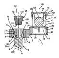
- FIG. 1is an exploded view of the first embodiment of the current invention
- FIG. 2is a sectional view of a second embodiment of the invention of FIG. 1 , showing the fastener holding member formed integrally with a bone fastener; and providing further illustration of a tensioner, holding member expansion feature, and longitudinal rod coupler;
- FIG. 3is a sectional view of a third embodiment of the present invention, showing the fastener holding member formed integrally with a pedicle hook;
- FIG. 4is a sectional view of a fourth embodiment of the present invention, showing an alternate arrangement of the longitudinal rod coupler.
- FIGS. 1 and 2show a coupling 3 , a fastener holding member 10 having a tensioner 12 for releasably fixing a bone fastener 2 to a longitudinal rod coupler 13 with a rod locking element 33 configured for releasably fixing a longitudinal rod 1 to the coupling 3 .
- the coupling 3has a longitudinal axis 30 , a top surface 5 configured to contact the longitudinal rod 1 , a bottom surface 6 , and a fastener coupling bore 7 which connects the top and bottom surfaces 5 , 6 .
- Fastener coupling bore 7further has an axis 11 that is substantially perpendicular to the coupling longitudinal axis 30 .
- the coupling 3has a rod coupling bore 19 which connects the coupling top and bottom surfaces 5 , 6 and has an axis 14 which is substantially parallel to the fastener coupling bore axis 11 .
- the fastener and rod coupling bores 7 , 19are separated by at a distance 31 measured along the coupling longitudinal axis 30 .
- the rod coupling bore 19is configured to slidingly receive a cylindrical articulating portion 130 of longitudinal rod coupler 13 such that the coupler 13 may rotate within the bore 19 , about the rod coupling bore axis 14 .
- the bottom end portion 16 of the rod coupler 13comprises an increased-diameter flange portion 35 , configured to mate with a corresponding recess 27 in the rod coupling bore 19 , so that when the rod coupler articulating portion 130 is inserted into the rod coupling bore 19 , the coupler flange portion 35 axially engages the rod coupler recess 27 , preventing further axial movement of the rod coupler 13 with respect to the coupling 3 in the insertion direction.
- the fastener coupling bore 7may comprise a partial spherical profile, the top and bottom portions of the sphere being intersected and cut by coupling 3 top and bottom surfaces 5 , 6 .
- the fastener holding member 10may have a partial spherical outer surface profile designed to correspond to the fastener coupling bore 7 inner surface. The corresponding spherical surfaces allow the fastener holding member 10 to be received in the fastener coupling bore 7 so that the holding member 10 is fully pivotable within the bore (i.e., it may rotate about any one of, or combination of, three orthogonal axes).
- the fastener holding member 10may further comprise top and bottom surfaces 20 , 21 positioned adjacent the coupling 3 top and bottom surfaces 5 , 6 respectively.
- the holding member 10may further comprise a conical bore 23 having an axis 230 , when installed, concentric to the fastener coupling bore axis 11 and including a conical internal screw thread 24 .
- the fastener holding member 10further may be configured so that its angular position within the fastener coupling bore 7 is lockable. Such a configuration may allow the user to lock the position of the associated fastener 2 in the desired pivot position, immobilizing it with respect to the coupling 3 .
- This locking featuremay be effected by providing a radial expansion feature within the holding member 10 , so that when the desired holding member/fastener position is obtained at least a portion of the holding member 10 spherical surface may be expanded to contact or interfere with the fastener coupling bore 7 , the frictional contact between surfaces preventing further relative movement.
- This radial expansion featuremay be provided in the form of at least one vertical slot 101 located in the holding member 10 , between the holding member outer spherical surface and conical bore surface 23 .
- the at least one slot 101may extend along a portion of the height of the holding member 10 , and may be parallel to the holding member bore axis 230 .
- the slot or slots 101may intersect the top end surface 20 of the holding member 10 , but not the bottom end surface 21 .
- the slot or slots 101may intersect the bottom end surface 20 but not the top end surface 21 .
- the fastener holding member 10comprises a series of parallel vertical slots evenly spaced about the circumference of the holding member 10 , each slot intersecting one of the top or bottom end surfaces 20 , 21 of the holding member 10 .
- a tensioner 12may be provided to radially expand the holding member 10 to its aforementioned locked position.
- the tensioner 12may comprise a frustoconical outer surface 120 corresponding to the holding member conical bore 23 and further may be provided with a conical external screw thread 25 corresponding to the holding member bore threads 24 .
- the tensioner 12may have an adjustment end 121 and a leading end 122 , the adjustment end 121 comprising a connection 123 suitable for engagement with a standard driving tool. Due to the conical shape of the tensioner 12 , the adjustment end 121 has a larger outer diameter than the leading end 122 .
- the holding member 10may be expanded by threadably driving the tensioner 12 into the bore so that the larger diameter adjustment end 121 enters a relatively smaller diameter portion of the holding member conical bore 23 , forcing open the at least one vertical slot 101 in the holding member 10 .
- Such expansion of the at least one slot 101may be sufficient to press the holding member 10 outer surface against the fastener coupling bore 7 , fixing the holding member 10 to the coupling bore 7 , and coupling 3 , as previously described.
- the tensioner 12itself comprises the head portion 8 of the bone fastener 2 .
- the holding member 10comprises the head portion 8 of the bone fastener 2 .
- the bone fastener 2may be a bone screw 9 or a pedicle hook 90 .
- the tensioner 12is integral to the head portion 8 of the bone fastener 2
- the bone fastener 2may be releasably fixed to the coupling 3 by threadably driving the head portion 8 into the holding member 10 , the corresponding conical surfaces 23 , 120 , threads 24 , 25 and at least one slot 101 serving to expand the holding member 10 and fix the fastener 2 to the fastener coupling bore 7 .
- a longitudinal rod coupler 13is used to receive and engage the longitudinal rod 1 .
- the rod coupler 13may have an articulating portion 130 that is configured to be rotatable and axially slidable within rod coupling bore 19 , and which has an axis 131 that, when the coupler 13 is engaged with the coupling 3 , is substantially coaxial to the rod coupling bore axis 14 .
- the rod coupler 13may also have a rod receiving portion 132 which, in one embodiment, comprises a channel 17 having a channel axis 32 oriented substantially perpendicular to the rod coupling bore axis 14 .
- the channel 17may have at least one vertical leg 133 configured to retain the longitudinal rod in at least a direction substantially perpendicular to the rod longitudinal axis 4 .
- the longitudinal rod coupler 13may have a top end 15 , adjacent to which channel 17 is open.
- the longitudinal rod coupler 13may also have a bottom end 16 opposite the top end 15 , and adjacent to the coupling bottom surface 6 .
- the bottom end 16may comprise an increased portion 35 having a diameter greater than the diameter of the rod coupling bore 19 , so that when the rod coupler 13 is inserted into the rod coupling bore 19 , the increased portion 35 prevents the rod coupler 13 from passing through the coupling bore 19 completely.
- the bottom surface 6 of the coupling 3may comprise a corresponding recess 27 configured to engage the increased portion 35 .
- the increased portionmay comprise a conical flange 26
- the coupling 3may comprise a correspondingly conical recess 27
- at least one of the conical flange 26 or coupling recess 27 , or both,may comprise serrations 28 .
- the channel 17may be configured so that it is open at the top end 15 of the longitudinal rod coupler 13 .
- a rod locking element 33comprises a locking cap 133 may be provided.
- This cap 133may comprise internal threads 134 configured to engage corresponding external threads 34 formed in the top end 15 of the rod coupler 13 .
- the locking cap 133may be threaded onto the coupler top end 15 and rotated until a bottom surface 135 of the cap engages the longitudinal rod 1 , thereby sandwiching the longitudinal rod 1 between the cap 133 and the top surface 5 of the coupling 3 .
- the locking cap 133may be unscrewed and disengaged from the rod coupler top end 15 .
- the portion of the coupling 3 comprising the fastener coupling bore 7is recessed so that when a longitudinal rod 1 is engaged with the coupling 3 , and a bone fastener 2 and tensioner 12 are fully engaged in the holding member 10 , the fastener, tensioner and holding member are sufficiently recessed within the coupling 3 that the coupling 3 and rod 1 may be rotated without interference 360 degrees about the rod coupling bore axis 14 .
- FIG. 2shows an alternative embodiment in which the fastener holding member 10 comprises the head portion 8 of the bone fastener 2 , which, in this embodiment, is a bone screw 9 .
- the bottom end 16 of longitudinal rod coupler 13comprises a conical flange 26 , configured to be received in a complementary inner cone 27 formed in the rod coupling bore 19 of the coupling 3 .
- an at least partially circumferential tab segment 29is provided on the rod coupler articulating portion adjacent the channel. This tab segment is adapted to engage the top surface 5 of the coupling 3 when the rod coupler is inserted into the rod coupling bore 14 .
- the tab segment 29When the tab segment 29 engages the top surface 5 of the coupling 3 , it fixes the rod coupler 13 axially with respect to the coupling 3 and prevents the rod coupler 13 from backing out of the rod coupling bore 19 .
- the inner diameter of the rod coupling bore 19may be only slightly larger than the outer diameter of the articulating portion 130 .
- the articulation portion 130may, therefore, comprise at least one vertical slot 36 to allow the articulating portion 130 to be compressed so that the tab segment 29 can pass through the bottom surface 6 of the coupler and though the bore 19 .
- FIG. 3shows an alternative embodiment of the rod coupler 13 in which the holding member 10 comprises the head portion 8 of the bone fastener 2 , which, in this embodiment, is a pedicle hook 90 .
- the head portion of the pedicle hook 90comprises the spherically-shaped holding member 10 .
- FIG. 4shows a further embodiment of the coupling 3 in which channel 17 is open at the top end 15 to permit the longitudinal rod 1 to be inserted laterally into the longitudinal rod coupler 13 (i.e. in a direction perpendicular to the rod longitudinal axis 4 ).
- a sleeve 360including a rod engaging surface 361 , and two side walls 37 extending parallel to the rod coupling bore axis 14 , is placed over the rod receiving portion 132 (in this case channel 17 ) at the top end 15 to fix the longitudinal rod 1 relative to the longitudinal rod coupler 13 .
- the sleeve 360is then held in place by a nut 38 which may be screwed onto an external screw thread 34 on the channel top end 15 .
- the longitudinal rod 1is retained between the top surface 5 of the coupling 3 and the rod engaging surface 361 of the sleeve 360 .
- the side walls 37provide lateral fixation.
- the conical flange 26comprises radially aligned teeth (i.e., serrations, 28 which secure the rod coupler 13 and coupling 3 against relative rotational movement.
Landscapes
- Health & Medical Sciences (AREA)
- Orthopedic Medicine & Surgery (AREA)
- Surgery (AREA)
- Life Sciences & Earth Sciences (AREA)
- Neurology (AREA)
- Medical Informatics (AREA)
- Biomedical Technology (AREA)
- Heart & Thoracic Surgery (AREA)
- Engineering & Computer Science (AREA)
- Molecular Biology (AREA)
- Animal Behavior & Ethology (AREA)
- General Health & Medical Sciences (AREA)
- Public Health (AREA)
- Veterinary Medicine (AREA)
- Nuclear Medicine, Radiotherapy & Molecular Imaging (AREA)
- Surgical Instruments (AREA)
- Prostheses (AREA)
Abstract
Description
This application is a continuation of the US National Phase designation of co-pending international patent application No. PCT/CH00/00449, filed Aug. 24, 2000, the entire content of which is expressly incorporated herein by reference thereto.
The present invention relates to spinal fixation systems and, in particular, to a device for adjustably connecting a bone fastener to a longitudinal rod.
In the posterior treatment of spinal deformities, pedicle screws or hooks are used to connect vertebral bodies to a longitudinal rod. Prior to implantation, the longitudinal rod is shaped in a particular form so as to correct the deformity of the vertebral column. This technique has proved successful and meanwhile has come to be considered as state of the art.
Despite the development of new connecting techniques, such as the use of jaws with polyaxial bearings to connect the screws and the longitudinal rod, the intra-operative connection of the two elements remains problematic, particularly in cases of heavy spinal deformities. The problem lies in the fixed distance between the head of the pedicle screw and the longitudinal carrier. In other words, the polyaxial bearing of the screw head within the connecting jaw allows for variable screw angles but not for variable distances between the screw head and longitudinal rod carrier. A variable distance between the screw head or the end portion of the hook and the longitudinal rod carrier is desirable as it is not always possible to achieve 100 percent alignment of the vertebral column relative to the longitudinal rod.
It is accordingly an object of the invention to create an apparatus for connecting a pedicle screw or a pedicle hook to a longitudinal rod which provides a polyaxial bearing for the pedicle screw or pedicle hook and also provides a pivotable connection between the connector and the longitudinal rod, pivotable connection being lockable in any desired position.
The invention relates to a device for connecting a bone fastener to a longitudinal rod. The device comprises a connector with a coupling portion having two bores. Each bore has a longitudinal axis, and the axes are separated by a predetermined distance. The connector also has a holding member associated with the first bore and configured to engage the bone fastener to connect the fastener to the coupling. A rod coupler is associated with the second bore and comprises a bore engaging portion, a rod receiving portion and a locking member having a rod coupler engaging portion. The connector is configured so the rod and rod coupler may be rotated about the first bore longitudinal axis. In one embodiment, the holding member may be rotated about the second bore axis. In another embodiment, the rod coupler may be rotated about the second bore longitudinal axis. In yet another embodiment, the first and second bore axes are substantially parallel.
The holding member may comprise top and bottom surfaces and a wall having at least one vertical slot, the slot intersecting either the top or bottom surface. The holding member may have a bore configured to engage a bone fastener, and may also have locked and unlocked positions. A tensioner may be provided to engage the holding member bore to lock the holding member, rendering the holding member immobilized with respect to the coupler first bore, and immobilizing the bone fastener within the holding member.
The holding member and tensioner are configured so that when the tensioner engages the holding member to render it locked, the longitudinal rod and rod coupler may rotate 360 degrees within the second bore. In one embodiment, the tensioner may comprise the head of a bone fastener such as a bone screw or pedicle hook. Alternately, the holding member may comprise the head of a bone fastener.
The coupling portion first bore may comprise a substantially spherical inner surface and the holding member may comprise a correspondingly substantially spherical outer surface configured to slide within the inner surface. This configuration allows the holding member to rotate within the first bore about multiple axes, which may include axes both parallel and perpendicular to the first bore axis.
The holding member bore may have a conical profile and internal threads, and the tensioner may have a corresponding conical outer profile and external threads which mate with those of the bore. The holding member may be resiliently displaceable so that upon engagement with the tensioner, the holding member outer spherical surface may expand to engage the coupling first bore inner surface, configuring the holding member in the locked position. The holding member may have at least one slot configured to render the holding member resiliently displaceable.
The rod receiving portion may have at least one vertical leg configured to accept the longitudinal rod, and the rod coupling may have locked and unlocked positions. The rod coupler and holding member may, independent of each other, be configured in their respective locked or unlocked positions.
The rod receiving portion may comprise a channel having a longitudinal axis, a top distal from the bore engaging portion, and a bottom end opposite the top end. The channel longitudinal axis may be coaxial with that of the rod receiving portion. The top end of the channel may be open to allow a longitudinal rod to be introduced into the receiving portion by pressing the rod into the channel top end in a direction substantially parallel to the second bore axis.
The rod coupler bore engaging portion may comprise a bottom end having an increased portion having a dimension greater than that of the second bore, preventing the rod coupler from passing all the way through the coupling when the coupler is inserted into the bore. This increased portion may comprise a conical flange, and the second bore may have a corresponding conical recess adjacent the bottom surface of the coupling. The conical flange and recess may have corresponding engagement surfaces, and at least one of the engagement surfaces may have serrations to prevent relative movement of the flange and coupling bore.
An alternate embodiment of the connector may be provided for connecting a bone screw to a rod, the connector having a coupling with first and second bores separated by a predetermined distance, each bore having a longitudinal axis. A holding member may be associated with the first bore, and may be capable of engaging a bone screw. A rod coupler may be associated with the second bore, and may have a bore engaging portion and a rod receiving portion. The rod coupler may be rotatable about the second bore longitudinal axis.
The holding member and coupling first bore may have corresponding spherical surfaces configured to allow the holding member to rotate within the first bore about multiple axes.
The connector may also have a tensioner which may engage the holding member and immobilize the bone screw with respect to the holding member. The connector may be configured so that when the holding member engages the bone screw and the tensioner engages the holding member, and the rod coupler engages the longitudinal rod, the rod and rod coupler may be rotated 360 degrees within the second bore.
The rod coupler may be provided with first and second vertical legs to receive a longitudinal rod. A rod locking member may also be provided to engage a top portion of each of the first and second legs to retain the rod within the rod coupler along a direction perpendicular to a longitudinal axis of the rod. The rod locking member may have threads which engage corresponding threads in top portion of at least one of the first and second vertical legs of the rod coupler.
The first and second legs may each have a top end distal from the coupling, where the top ends are open to allow a rod to be introduced into the rod receiving portion by pressing the rod between the legs in a direction substantially parallel to the second bore axis. The rod receiving portion of the rod coupler may form a channel configured to allow a rod to be introduced into the rod receiving portion by threading the rod into the channel in a direction substantially perpendicular to the second bore axis.
The connector may also have a tensioner configured to engage the holding member to immobilize the bone screw with respect to the bone screw. The holding member may be radially expandable so that when engaged by the tensioner, the holding member spherical surface expands to engage the inner surface of the coupling first bore, thus locking the holding member to the coupling.
The rod locking member and rod coupler of this embodiment may be configured to engage the rod so that the rod may not move with respect to the rod coupler or rod locking member. The rod locking member and rod coupler may also be configured so that the rod is held between the rod locking member and a top surface of the connector. The rod coupler bore engaging portion may comprise a bottom end having an increased portion having a dimension greater than that of the second bore, wherein when the rod coupler is inserted into the second bore, the increased portion prevents the rod coupler from passing through the coupling. The increased portion may comprise a conical flange, and the second bore may have a corresponding conical recess adjacent to a bottom surface of the coupling. The conical flange and conical recess may have corresponding engaging surfaces, at least one of which may have serrations to prevent relative movement between the flange and bore.
The rod coupler bore engaging portion may further comprise a top end opposite the bottom end, the bore engaging portion further may comprise a second increased portion located at a point between the bore engaging portion top and bottom ends, the second increased portion having a dimension greater than that of the second bore, wherein when the rod coupler is inserted into the second bore, the first and second increased portions couple the rod coupler to the second bore. The rod coupler bore engaging portion may have at least one slot between the first and second increased portions, the at least one slot making at least part of the bore engaging portion resiliently displaceable to allow the second increase portion to be accepted within the second bore.
In yet another embodiment of the invention, a connector may be provided for connecting a bone screw to a rod, the connector having a coupling portion with first and second bores, each bore having a longitudinal axis, the axes separated by a predetermined distance, the first bore being associated with the bone screw. The connector also has a rod coupler associated with the second bore, the coupler having an articulating portion and a rod receiving portion. The articulating portion is configured to be rotatably and axially slidably receivable within the second bore. The rod receiving portion has at least one vertical leg configured to receive the rod in a direction substantially perpendicular to the second bore longitudinal axis. When the rod engages the rod coupler, the rod may be selectively rotated about the first bore longitudinal axis. The rod coupler may comprise a cap configured to engage the top end of the at least one vertical leg to retain the longitudinal rod in at least one direction perpendicular to the rod longitudinal axis.
The connector of this embodiment may further comprise a holding member associated with the first bore and configured to receive the bone screw. The holding member may have a bore configured to accept the bone screw, the holding member further having an unlocked position in which it is free to rotate within the first bore, and a locked position in which it is immobilized within the first bore. A tensioner may be provided to engage the holding member and configure the holding member in the locked position whereby the holding member is immobilized within the first bore. The tensioner may comprise external threads configured to engage internal threads of the holding member bore.
The connector is configured such that when the holding member engages the bone fastener, the tensioner engages the holding member, and the rod coupler engages the rod, the rod and rod coupler may be rotated 360 degrees about both the first and second bore longitudinal axes.
The first bore of the connector may have a substantially spherical inner surface and the holding member may have a substantially spherical outer surface configured to be slidably received within the first bore. The holding member may further be radially expandable such that when the tensioner engages the holding member bore, the holding member spherical outer surface expands to engage the inner spherical surface of the coupling first bore, thus locking the holding member to the coupling.
The holding member bore may have a conical profile and internal threads, and the tensioner may have a conical outer profile and external threads corresponding to the holding member bore.
The rod coupler may comprise a channel having a top end distal from the coupling portion and a bottom end proximal to the coupling portion, the channel top end being open to allow a rod having an axis substantially parallel to the channel axis to be introduced into the rod engaging portion by pressing the rod through the channel top end in a direction substantially parallel to the second bore axis.
The connector articulating portion may comprise an increased portion having a dimension greater than that of the second bore, such that when the rod coupler is inserted into the second bore, the increased portion prevents the rod coupler from passing through the coupling. The increased portion may comprise a conical flange, and the second bore may have a corresponding conical recess adjacent to the coupling portion bottom surface. The conical flange and bore may have corresponding engagement surfaces, and at least one engagement surface comprises serrations to prevent relative rotation between the flange and bore.
The holding member may have top and bottom surfaces and a wall. The wall may have at least one vertical slot intersecting at least the jaw top surface so that when the tensioner engages the holding member, the holding member expands along the at least one slot.
The features and advantages of the present invention will become more readily apparent from the following detailed description of the invention in which like elements are labeled similarly, and in which:
The rod coupling bore19 is configured to slidingly receive a cylindrical articulatingportion 130 oflongitudinal rod coupler 13 such that thecoupler 13 may rotate within thebore 19, about the rod coupling boreaxis 14. Thebottom end portion 16 of therod coupler 13 comprises an increased-diameter flange portion 35, configured to mate with acorresponding recess 27 in the rod coupling bore19, so that when the rodcoupler articulating portion 130 is inserted into the rod coupling bore19, thecoupler flange portion 35 axially engages therod coupler recess 27, preventing further axial movement of therod coupler 13 with respect to the coupling3 in the insertion direction.
The fastener coupling bore7 may comprise a partial spherical profile, the top and bottom portions of the sphere being intersected and cut by coupling3 top andbottom surfaces fastener holding member 10 may have a partial spherical outer surface profile designed to correspond to the fastener coupling bore7 inner surface. The corresponding spherical surfaces allow thefastener holding member 10 to be received in the fastener coupling bore7 so that the holdingmember 10 is fully pivotable within the bore (i.e., it may rotate about any one of, or combination of, three orthogonal axes).
Thefastener holding member 10 may further comprise top andbottom surfaces bottom surfaces member 10 may further comprise aconical bore 23 having anaxis 230, when installed, concentric to the fastener coupling boreaxis 11 and including a conicalinternal screw thread 24.
Thefastener holding member 10 further may be configured so that its angular position within the fastener coupling bore7 is lockable. Such a configuration may allow the user to lock the position of the associatedfastener 2 in the desired pivot position, immobilizing it with respect to the coupling3. This locking feature may be effected by providing a radial expansion feature within the holdingmember 10, so that when the desired holding member/fastener position is obtained at least a portion of the holdingmember 10 spherical surface may be expanded to contact or interfere with thefastener coupling bore 7, the frictional contact between surfaces preventing further relative movement. This radial expansion feature may be provided in the form of at least onevertical slot 101 located in the holdingmember 10, between the holding member outer spherical surface andconical bore surface 23. The at least oneslot 101 may extend along a portion of the height of the holdingmember 10, and may be parallel to the holding member boreaxis 230. The slot orslots 101 may intersect thetop end surface 20 of the holdingmember 10, but not thebottom end surface 21. Alternatively the slot orslots 101 may intersect thebottom end surface 20 but not thetop end surface 21. In one embodiment, thefastener holding member 10 comprises a series of parallel vertical slots evenly spaced about the circumference of the holdingmember 10, each slot intersecting one of the top or bottom end surfaces20,21 of the holdingmember 10.
Atensioner 12 may be provided to radially expand the holdingmember 10 to its aforementioned locked position. Thetensioner 12 may comprise a frustoconicalouter surface 120 corresponding to the holding member conical bore23 and further may be provided with a conicalexternal screw thread 25 corresponding to the holding member borethreads 24. Thetensioner 12 may have anadjustment end 121 and aleading end 122, theadjustment end 121 comprising aconnection 123 suitable for engagement with a standard driving tool. Due to the conical shape of thetensioner 12, theadjustment end 121 has a larger outer diameter than theleading end 122. Under this arrangement, the holdingmember 10 may be expanded by threadably driving thetensioner 12 into the bore so that the largerdiameter adjustment end 121 enters a relatively smaller diameter portion of the holding member conical bore23, forcing open the at least onevertical slot 101 in the holdingmember 10. Such expansion of the at least oneslot 101 may be sufficient to press the holdingmember 10 outer surface against thefastener coupling bore 7, fixing the holdingmember 10 to thecoupling bore 7, and coupling3, as previously described.
In one embodiment, thetensioner 12 itself comprises thehead portion 8 of thebone fastener 2. In an alternate embodiment, the holdingmember 10 comprises thehead portion 8 of thebone fastener 2. Thebone fastener 2 may be abone screw 9 or apedicle hook 90. Where thetensioner 12 is integral to thehead portion 8 of thebone fastener 2, thebone fastener 2 may be releasably fixed to the coupling3 by threadably driving thehead portion 8 into the holdingmember 10, the correspondingconical surfaces threads slot 101 serving to expand the holdingmember 10 and fix thefastener 2 to thefastener coupling bore 7.
Alongitudinal rod coupler 13 is used to receive and engage thelongitudinal rod 1. Therod coupler 13 may have an articulatingportion 130 that is configured to be rotatable and axially slidable within rod coupling bore19, and which has anaxis 131 that, when thecoupler 13 is engaged with the coupling3, is substantially coaxial to the rod coupling boreaxis 14. Therod coupler 13 may also have arod receiving portion 132 which, in one embodiment, comprises achannel 17 having achannel axis 32 oriented substantially perpendicular to the rod coupling boreaxis 14. Thechannel 17 may have at least onevertical leg 133 configured to retain the longitudinal rod in at least a direction substantially perpendicular to the rodlongitudinal axis 4.
Thelongitudinal rod coupler 13 may have atop end 15, adjacent to whichchannel 17 is open. Thelongitudinal rod coupler 13 may also have abottom end 16 opposite thetop end 15, and adjacent to thecoupling bottom surface 6. Thebottom end 16 may comprise an increasedportion 35 having a diameter greater than the diameter of the rod coupling bore19, so that when therod coupler 13 is inserted into the rod coupling bore19, the increasedportion 35 prevents therod coupler 13 from passing through the coupling bore19 completely. Where thebottom end 16 comprises an increasedportion 35, thebottom surface 6 of the coupling3 may comprise acorresponding recess 27 configured to engage the increasedportion 35. In one embodiment, the increased portion may comprise aconical flange 26, and the coupling3 may comprise a correspondinglyconical recess 27. To prevent post-installation rotation between the coupling3 and thelongitudinal rod coupler 13, at least one of theconical flange 26 orcoupling recess 27, or both, may compriseserrations 28.
Thechannel 17 may be configured so that it is open at thetop end 15 of thelongitudinal rod coupler 13. To capture thelongitudinal rod 1 within therod coupler channel 17, arod locking element 33. In one embodiment, therod locking element 33 comprises alocking cap 133 may be provided. Thiscap 133 may compriseinternal threads 134 configured to engage correspondingexternal threads 34 formed in thetop end 15 of therod coupler 13. Upon insertion of thelongitudinal rod 1 in thechannel 17, the lockingcap 133 may be threaded onto the couplertop end 15 and rotated until abottom surface 135 of the cap engages thelongitudinal rod 1, thereby sandwiching thelongitudinal rod 1 between thecap 133 and thetop surface 5 of the coupling3. To release thelongitudinal rod 1, the lockingcap 133 may be unscrewed and disengaged from the rod couplertop end 15.
In one embodiment, the portion of the coupling3 comprising the fastener coupling bore7 is recessed so that when alongitudinal rod 1 is engaged with the coupling3, and abone fastener 2 andtensioner 12 are fully engaged in the holdingmember 10, the fastener, tensioner and holding member are sufficiently recessed within the coupling3 that the coupling3 androd 1 may be rotated withoutinterference 360 degrees about the rod coupling boreaxis 14.
Accordingly, it should be understood that the embodiments disclosed herein are merely illustrative of the principles of the invention. Various other modifications may be made by those skilled in the art that will embody the principles of the invention and fall within the spirit and the scope thereof.
Claims (16)
1. A connector for connecting a bone fastener to at rod, comprising:
a coupling portion having a top surface, a bottom surface and first and second bores, each bore having a longitudinal axis, the axes separated by a predetermined distance;
a holding member associated with the first bore arid configured to engage the bone fastener to connect the bone fastener to the coupling portion; the holding member having a top surface, a bottom surface, a wall extending from the top surface to the bottom surface, at least one vertical slot disposed in the wall and intersecting one of the top and bottom surfaces, and a bore extending therethrough sized and configured to accept the bone fastener, the holding member further having a locked position and an unlocked position;
a rod coupler associated with the second bore and comprising a bore engaging portion, a rod receiving portion having an axis, a locking member having a rod coupler engaging portion and a substantially circumferential tab segment, wherein the bore engaging portion has a bottom end with an increased portion having a dimension greater than that of the second bore so that when the rod coupler is inserted into the second bore, the increased portion prevents the rod coupler from passing through the coupling portion and the tab segment contacts the top surface of the coupling portion when the rod coupler is inserted into the second bore so that the rod coupler is axially fixed with respect to the coupling portion; and
a tensioner sized and configured to be received within the bore formed in the holding member, the tensioner configured to engage the holding member to secure the holding member in the locked position whereby the holding member is immobilized with respect to the coupling portion and the bone fastener is immobilized within the holding member;
wherein the rod and rod coupler are selectively rotatable about the first bore longitudinal axis.
2. The connector ofclaim 1 , wherein the holding member may be rotated about the second bore longitudinal axis.
3. The connector ofclaim 1 , wherein the rod coupler may be rotated about the second bore longitudinal axis.
4. The connector ofclaim 1 , wherein the first and second bore longitudinal axes are substantially parallel.
5. The connector ofclaim 1 , wherein when the tensioner engages the holding member to configure the holding member in the locked position, the longitudinal rod and rod coupler may be rotated 360 degrees within the second bore.
6. The connector ofclaim 1 , wherein the tensioner comprises a head portion of the bone fastener.
7. The connector ofclaim 1 , wherein the coupling portion first bore comprises a substantially spherical inner surface and the holding member comprises a substantially spherical outer surface configured to slide within the spherical bore inner surface so that the holding member may rotate within the first bore about multiple axes.
8. The connector ofclaim 7 , wherein the holding member may slide within the spherical bore inner surface about axes both parallel and perpendicular to the first bore axis.
9. The connector ofclaim 7 , wherein the holding member bore has a conical profile and internal threads, the tensioner further comprising a conical outer profile and external threads corresponding to the bore.
10. The connector ofclaim 9 , the holding member configured to be resiliently displaceable so that when the tensioner engage the bore the holding member outer spherical surface may expand to engage the coupling first bore inner spherical surface, configuring the holding member in the locked position.
11. The connector ofclaim 1 , wherein the rod receiving portion has at least one vertical leg configured to accept the longitudinal rod, the rod coupler further having locked and unlocked positions.
12. The connector ofclaim 1 , wherein the rod coupler also has a locked position and an unlocked position, wherein the rod coupler and the holding member are, independently positionable between their respective locked or unlocked positions.
13. The connector ofclaim 1 , wherein the holding member comprises a head portion of the bone fastener.
14. The connector ofclaim 1 , wherein the rod receiving portion of the rod coupler comprises a channel having a longitudinal axis, a top end distal from the bore engaging portion and a bottom end opposite the top end, the channel longitudinal axis coaxial with the rod receiving portion axis, the channel top end being open to allow a rod to be introduced into the rod receiving portion by pressing the rod through the channel top end in a direction substantially parallel to the second bore axis.
15. The connector ofclaim 1 , wherein the increased portion comprises a conical flange, the second bore further comprises a corresponding conical recess adjacent to a bottom surface of the coupling portion.
16. The connector ofclaim 15 wherein the conical flange and conical recess have corresponding engagement surfaces, and at least one of the engagement surfaces comprises serrations configured to prevent relative rotation between the flange and the bore.
Priority Applications (1)
| Application Number | Priority Date | Filing Date | Title |
|---|---|---|---|
| US11/182,677US20050251141A1 (en) | 2000-08-24 | 2005-07-15 | Apparatus for connecting a bone fastener to a longitudinal rod |
Applications Claiming Priority (1)
| Application Number | Priority Date | Filing Date | Title |
|---|---|---|---|
| PCT/CH2000/000449WO2002015806A1 (en) | 2000-08-24 | 2000-08-24 | Device for connecting a bone fixation element to a longitudinal rod |
Related Parent Applications (1)
| Application Number | Title | Priority Date | Filing Date |
|---|---|---|---|
| PCT/CH2000/000449ContinuationWO2002015806A1 (en) | 2000-08-24 | 2000-08-24 | Device for connecting a bone fixation element to a longitudinal rod |
Related Child Applications (1)
| Application Number | Title | Priority Date | Filing Date |
|---|---|---|---|
| US11/182,677ContinuationUS20050251141A1 (en) | 2000-08-24 | 2005-07-15 | Apparatus for connecting a bone fastener to a longitudinal rod |
Publications (2)
| Publication Number | Publication Date |
|---|---|
| US20030149432A1 US20030149432A1 (en) | 2003-08-07 |
| US6945972B2true US6945972B2 (en) | 2005-09-20 |
Family
ID=4358118
Family Applications (2)
| Application Number | Title | Priority Date | Filing Date |
|---|---|---|---|
| US10/372,345Expired - LifetimeUS6945972B2 (en) | 2000-08-24 | 2003-02-24 | Apparatus for connecting a bone fastener to a longitudinal rod |
| US11/182,677AbandonedUS20050251141A1 (en) | 2000-08-24 | 2005-07-15 | Apparatus for connecting a bone fastener to a longitudinal rod |
Family Applications After (1)
| Application Number | Title | Priority Date | Filing Date |
|---|---|---|---|
| US11/182,677AbandonedUS20050251141A1 (en) | 2000-08-24 | 2005-07-15 | Apparatus for connecting a bone fastener to a longitudinal rod |
Country Status (16)
| Country | Link |
|---|---|
| US (2) | US6945972B2 (en) |
| EP (1) | EP1311198B1 (en) |
| JP (1) | JP2004505745A (en) |
| KR (1) | KR100773965B1 (en) |
| CN (1) | CN1247162C (en) |
| AR (1) | AR030330A1 (en) |
| AT (1) | ATE367773T1 (en) |
| AU (2) | AU6423300A (en) |
| BR (1) | BR0017321A (en) |
| CA (1) | CA2419798A1 (en) |
| DE (1) | DE50014519D1 (en) |
| ES (1) | ES2288864T3 (en) |
| MX (1) | MXPA03001628A (en) |
| MY (1) | MY124899A (en) |
| TW (1) | TW565436B (en) |
| WO (1) | WO2002015806A1 (en) |
Cited By (131)
| Publication number | Priority date | Publication date | Assignee | Title |
|---|---|---|---|---|
| US20050177164A1 (en)* | 2003-05-02 | 2005-08-11 | Carmen Walters | Pedicle screw devices, systems and methods having a preloaded set screw |
| US20050177166A1 (en)* | 2003-05-02 | 2005-08-11 | Timm Jens P. | Mounting mechanisms for pedicle screws and related assemblies |
| US20050182401A1 (en)* | 2003-05-02 | 2005-08-18 | Timm Jens P. | Systems and methods for spine stabilization including a dynamic junction |
| US20050182409A1 (en)* | 2003-05-02 | 2005-08-18 | Ronald Callahan | Systems and methods accommodating relative motion in spine stabilization |
| US20050251141A1 (en)* | 2000-08-24 | 2005-11-10 | Synthes Usa | Apparatus for connecting a bone fastener to a longitudinal rod |
| US20060195104A1 (en)* | 2003-08-08 | 2006-08-31 | Christoph Schlafli | Clamping device |
| US20060241596A1 (en)* | 2005-04-26 | 2006-10-26 | Alan Rezach | Open dorsal adjusting connector |
| US20070191835A1 (en)* | 2006-01-27 | 2007-08-16 | Sdgi Holdings, Inc. | Pivoting joints for spinal implants including designed resistance to motion and methods of use |
| US20070191839A1 (en)* | 2006-01-27 | 2007-08-16 | Sdgi Holdings, Inc. | Non-locking multi-axial joints in a vertebral implant and methods of use |
| US20070233078A1 (en)* | 2006-01-27 | 2007-10-04 | Justis Jeff R | Pivoting joints for spinal implants including designed resistance to motion and methods of use |
| US20070288012A1 (en)* | 2006-04-21 | 2007-12-13 | Dennis Colleran | Dynamic motion spinal stabilization system and device |
| US20070293862A1 (en)* | 2005-09-30 | 2007-12-20 | Jackson Roger P | Dynamic stabilization connecting member with elastic core and outer sleeve |
| US7527639B2 (en)* | 2000-02-01 | 2009-05-05 | Depuy Products, Inc. | Fixation system with multidirectional bone supports |
| US20090264933A1 (en)* | 2008-04-22 | 2009-10-22 | Warsaw Orthopedic, Inc. | Anchors for securing a rod to a vertebral member |
| US7662175B2 (en) | 2003-06-18 | 2010-02-16 | Jackson Roger P | Upload shank swivel head bone screw spinal implant |
| US7766915B2 (en) | 2004-02-27 | 2010-08-03 | Jackson Roger P | Dynamic fixation assemblies with inner core and outer coil-like member |
| US7766911B1 (en) | 2002-07-05 | 2010-08-03 | Theken Spine, Llc | Fixed and variable locking fixation assembly |
| US7780664B2 (en) | 2002-12-10 | 2010-08-24 | Depuy Products, Inc. | Endosteal nail |
| US20100234892A1 (en)* | 2008-10-15 | 2010-09-16 | Keyvan Mazda | Spinal interconnecting device and a stabilizing system using said device |
| US20100241175A1 (en)* | 2009-03-20 | 2010-09-23 | Spinal USA LLC | Pedicle screws and methods of using the same |
| US7854752B2 (en) | 2004-08-09 | 2010-12-21 | Theken Spine, Llc | System and method for dynamic skeletal stabilization |
| US20110015677A1 (en)* | 2004-03-03 | 2011-01-20 | Biedermann Motech Gmbh | Anchoring element and stabilization device for the dynamic stabilization of vertebrae or bones using such anchoring elements |
| US7875065B2 (en) | 2004-11-23 | 2011-01-25 | Jackson Roger P | Polyaxial bone screw with multi-part shank retainer and pressure insert |
| US7901437B2 (en) | 2007-01-26 | 2011-03-08 | Jackson Roger P | Dynamic stabilization member with molded connection |
| US7942911B2 (en) | 2007-05-16 | 2011-05-17 | Ortho Innovations, Llc | Polyaxial bone screw |
| US7942910B2 (en) | 2007-05-16 | 2011-05-17 | Ortho Innovations, Llc | Polyaxial bone screw |
| US7942909B2 (en) | 2009-08-13 | 2011-05-17 | Ortho Innovations, Llc | Thread-thru polyaxial pedicle screw system |
| US7947065B2 (en) | 2008-11-14 | 2011-05-24 | Ortho Innovations, Llc | Locking polyaxial ball and socket fastener |
| US7951173B2 (en) | 2007-05-16 | 2011-05-31 | Ortho Innovations, Llc | Pedicle screw implant system |
| US7951170B2 (en) | 2007-05-31 | 2011-05-31 | Jackson Roger P | Dynamic stabilization connecting member with pre-tensioned solid core |
| US7967850B2 (en) | 2003-06-18 | 2011-06-28 | Jackson Roger P | Polyaxial bone anchor with helical capture connection, insert and dual locking assembly |
| US8012177B2 (en) | 2007-02-12 | 2011-09-06 | Jackson Roger P | Dynamic stabilization assembly with frusto-conical connection |
| US8021398B2 (en) | 2004-06-09 | 2011-09-20 | Life Spine, Inc. | Spinal fixation system |
| US8025681B2 (en) | 2006-03-29 | 2011-09-27 | Theken Spine, Llc | Dynamic motion spinal stabilization system |
| US8057519B2 (en) | 2006-01-27 | 2011-11-15 | Warsaw Orthopedic, Inc. | Multi-axial screw assembly |
| US8066739B2 (en) | 2004-02-27 | 2011-11-29 | Jackson Roger P | Tool system for dynamic spinal implants |
| US8075603B2 (en) | 2008-11-14 | 2011-12-13 | Ortho Innovations, Llc | Locking polyaxial ball and socket fastener |
| US8092500B2 (en) | 2007-05-01 | 2012-01-10 | Jackson Roger P | Dynamic stabilization connecting member with floating core, compression spacer and over-mold |
| US8092502B2 (en) | 2003-04-09 | 2012-01-10 | Jackson Roger P | Polyaxial bone screw with uploaded threaded shank and method of assembly and use |
| US8100915B2 (en) | 2004-02-27 | 2012-01-24 | Jackson Roger P | Orthopedic implant rod reduction tool set and method |
| US8105368B2 (en) | 2005-09-30 | 2012-01-31 | Jackson Roger P | Dynamic stabilization connecting member with slitted core and outer sleeve |
| US8128667B2 (en) | 2002-09-06 | 2012-03-06 | Jackson Roger P | Anti-splay medical implant closure with multi-surface removal aperture |
| US8137386B2 (en) | 2003-08-28 | 2012-03-20 | Jackson Roger P | Polyaxial bone screw apparatus |
| US8152810B2 (en) | 2004-11-23 | 2012-04-10 | Jackson Roger P | Spinal fixation tool set and method |
| US8197518B2 (en) | 2007-05-16 | 2012-06-12 | Ortho Innovations, Llc | Thread-thru polyaxial pedicle screw system |
| US8257402B2 (en) | 2002-09-06 | 2012-09-04 | Jackson Roger P | Closure for rod receiving orthopedic implant having left handed thread removal |
| US8257398B2 (en) | 2003-06-18 | 2012-09-04 | Jackson Roger P | Polyaxial bone screw with cam capture |
| US8273109B2 (en) | 2002-09-06 | 2012-09-25 | Jackson Roger P | Helical wound mechanically interlocking mating guide and advancement structure |
| US8308782B2 (en) | 2004-11-23 | 2012-11-13 | Jackson Roger P | Bone anchors with longitudinal connecting member engaging inserts and closures for fixation and optional angulation |
| US8353932B2 (en) | 2005-09-30 | 2013-01-15 | Jackson Roger P | Polyaxial bone anchor assembly with one-piece closure, pressure insert and plastic elongate member |
| US8366753B2 (en) | 2003-06-18 | 2013-02-05 | Jackson Roger P | Polyaxial bone screw assembly with fixed retaining structure |
| US8366745B2 (en) | 2007-05-01 | 2013-02-05 | Jackson Roger P | Dynamic stabilization assembly having pre-compressed spacers with differential displacements |
| US8377102B2 (en) | 2003-06-18 | 2013-02-19 | Roger P. Jackson | Polyaxial bone anchor with spline capture connection and lower pressure insert |
| US8377100B2 (en) | 2000-12-08 | 2013-02-19 | Roger P. Jackson | Closure for open-headed medical implant |
| US8388660B1 (en) | 2006-08-01 | 2013-03-05 | Samy Abdou | Devices and methods for superior fixation of orthopedic devices onto the vertebral column |
| US8398682B2 (en) | 2003-06-18 | 2013-03-19 | Roger P. Jackson | Polyaxial bone screw assembly |
| US8444681B2 (en) | 2009-06-15 | 2013-05-21 | Roger P. Jackson | Polyaxial bone anchor with pop-on shank, friction fit retainer and winged insert |
| US8475498B2 (en) | 2007-01-18 | 2013-07-02 | Roger P. Jackson | Dynamic stabilization connecting member with cord connection |
| US8545538B2 (en) | 2005-12-19 | 2013-10-01 | M. Samy Abdou | Devices and methods for inter-vertebral orthopedic device placement |
| US8551088B2 (en) | 2008-03-31 | 2013-10-08 | Applied Medical Resources Corporation | Electrosurgical system |
| US8556938B2 (en) | 2009-06-15 | 2013-10-15 | Roger P. Jackson | Polyaxial bone anchor with non-pivotable retainer and pop-on shank, some with friction fit |
| US8591515B2 (en) | 2004-11-23 | 2013-11-26 | Roger P. Jackson | Spinal fixation tool set and method |
| US8617209B2 (en) | 2004-06-09 | 2013-12-31 | Life Spine, Inc. | Spinal fixation system |
| US20140052189A1 (en)* | 2012-08-15 | 2014-02-20 | Blackstone Medical, Inc. | Pivoting spinal fixation devices |
| US8672978B2 (en) | 2011-03-04 | 2014-03-18 | Zimmer Spine, Inc. | Transverse connector |
| US8814911B2 (en) | 2003-06-18 | 2014-08-26 | Roger P. Jackson | Polyaxial bone screw with cam connection and lock and release insert |
| US8814913B2 (en) | 2002-09-06 | 2014-08-26 | Roger P Jackson | Helical guide and advancement flange with break-off extensions |
| US8845649B2 (en) | 2004-09-24 | 2014-09-30 | Roger P. Jackson | Spinal fixation tool set and method for rod reduction and fastener insertion |
| US8876868B2 (en) | 2002-09-06 | 2014-11-04 | Roger P. Jackson | Helical guide and advancement flange with radially loaded lip |
| US8911479B2 (en) | 2012-01-10 | 2014-12-16 | Roger P. Jackson | Multi-start closures for open implants |
| US8911477B2 (en) | 2007-10-23 | 2014-12-16 | Roger P. Jackson | Dynamic stabilization member with end plate support and cable core extension |
| US8936623B2 (en) | 2003-06-18 | 2015-01-20 | Roger P. Jackson | Polyaxial bone screw assembly |
| US8979904B2 (en) | 2007-05-01 | 2015-03-17 | Roger P Jackson | Connecting member with tensioned cord, low profile rigid sleeve and spacer with torsion control |
| US8992579B1 (en) | 2011-03-08 | 2015-03-31 | Nuvasive, Inc. | Lateral fixation constructs and related methods |
| US8998959B2 (en) | 2009-06-15 | 2015-04-07 | Roger P Jackson | Polyaxial bone anchors with pop-on shank, fully constrained friction fit retainer and lock and release insert |
| US9005249B2 (en) | 2011-07-11 | 2015-04-14 | Life Spine, Inc. | Spinal rod connector assembly |
| US9050139B2 (en) | 2004-02-27 | 2015-06-09 | Roger P. Jackson | Orthopedic implant rod reduction tool set and method |
| US9060815B1 (en) | 2012-03-08 | 2015-06-23 | Nuvasive, Inc. | Systems and methods for performing spine surgery |
| US9168069B2 (en) | 2009-06-15 | 2015-10-27 | Roger P. Jackson | Polyaxial bone anchor with pop-on shank and winged insert with lower skirt for engaging a friction fit retainer |
| US9198695B2 (en) | 2010-08-30 | 2015-12-01 | Zimmer Spine, Inc. | Polyaxial pedicle screw |
| US9216041B2 (en) | 2009-06-15 | 2015-12-22 | Roger P. Jackson | Spinal connecting members with tensioned cords and rigid sleeves for engaging compression inserts |
| US9216039B2 (en) | 2004-02-27 | 2015-12-22 | Roger P. Jackson | Dynamic spinal stabilization assemblies, tool set and method |
| USD748259S1 (en) | 2014-12-29 | 2016-01-26 | Applied Medical Resources Corporation | Electrosurgical instrument |
| US9247962B2 (en) | 2011-08-15 | 2016-02-02 | K2M, Inc. | Laminar hook insertion device |
| US9283002B2 (en) | 2010-12-21 | 2016-03-15 | Zimmer Spine | Orthopaedic device and methods for its pre-assembly and assembly |
| US9320563B2 (en) | 2010-10-01 | 2016-04-26 | Applied Medical Resources Corporation | Electrosurgical instruments and connections thereto |
| US9414863B2 (en) | 2005-02-22 | 2016-08-16 | Roger P. Jackson | Polyaxial bone screw with spherical capture, compression insert and alignment and retention structures |
| US9451989B2 (en) | 2007-01-18 | 2016-09-27 | Roger P Jackson | Dynamic stabilization members with elastic and inelastic sections |
| US9451992B2 (en)* | 2010-12-01 | 2016-09-27 | Facet-Link Inc. | Variable angle bone screw fixation arrangement |
| US9453526B2 (en) | 2013-04-30 | 2016-09-27 | Degen Medical, Inc. | Bottom-loading anchor assembly |
| US9468479B2 (en) | 2013-09-06 | 2016-10-18 | Cardinal Health 247, Inc. | Bone plate |
| US9480517B2 (en) | 2009-06-15 | 2016-11-01 | Roger P. Jackson | Polyaxial bone anchor with pop-on shank, shank, friction fit retainer, winged insert and low profile edge lock |
| US9517089B1 (en)* | 2013-10-08 | 2016-12-13 | Nuvasive, Inc. | Bone anchor with offset rod connector |
| US9743959B2 (en)* | 2013-03-14 | 2017-08-29 | Atlas Spine, Inc. | Low profile spinal fixation system |
| US9743957B2 (en) | 2004-11-10 | 2017-08-29 | Roger P. Jackson | Polyaxial bone screw with shank articulation pressure insert and method |
| US20170273719A1 (en)* | 2014-01-23 | 2017-09-28 | K2M, Inc. | Spinal stabilization system |
| US9844398B2 (en) | 2012-05-11 | 2017-12-19 | Orthopediatrics Corporation | Surgical connectors and instrumentation |
| US9907574B2 (en) | 2008-08-01 | 2018-03-06 | Roger P. Jackson | Polyaxial bone anchors with pop-on shank, friction fit fully restrained retainer, insert and tool receiving features |
| US9980753B2 (en) | 2009-06-15 | 2018-05-29 | Roger P Jackson | pivotal anchor with snap-in-place insert having rotation blocking extensions |
| US10039578B2 (en) | 2003-12-16 | 2018-08-07 | DePuy Synthes Products, Inc. | Methods and devices for minimally invasive spinal fixation element placement |
| US10149713B2 (en) | 2014-05-16 | 2018-12-11 | Applied Medical Resources Corporation | Electrosurgical system |
| US10194951B2 (en) | 2005-05-10 | 2019-02-05 | Roger P. Jackson | Polyaxial bone anchor with compound articulation and pop-on shank |
| US10258386B2 (en)* | 2017-06-15 | 2019-04-16 | Warsaw Orthopedic, Inc. | Spinal construct and method |
| US10258382B2 (en) | 2007-01-18 | 2019-04-16 | Roger P. Jackson | Rod-cord dynamic connection assemblies with slidable bone anchor attachment members along the cord |
| US10299839B2 (en) | 2003-12-16 | 2019-05-28 | Medos International Sárl | Percutaneous access devices and bone anchor assemblies |
| US10363070B2 (en) | 2009-06-15 | 2019-07-30 | Roger P. Jackson | Pivotal bone anchor assemblies with pressure inserts and snap on articulating retainers |
| US10383660B2 (en) | 2007-05-01 | 2019-08-20 | Roger P. Jackson | Soft stabilization assemblies with pretensioned cords |
| US10413331B2 (en) | 2016-12-21 | 2019-09-17 | Spine Wave, Inc. | Spinal stabilization system with head to head cross connector |
| US10420603B2 (en) | 2014-12-23 | 2019-09-24 | Applied Medical Resources Corporation | Bipolar electrosurgical sealer and divider |
| US10524841B2 (en)* | 2009-09-02 | 2020-01-07 | Globus Medical, Inc. | Spine stabilization system |
| US10543107B2 (en) | 2009-12-07 | 2020-01-28 | Samy Abdou | Devices and methods for minimally invasive spinal stabilization and instrumentation |
| US10548740B1 (en) | 2016-10-25 | 2020-02-04 | Samy Abdou | Devices and methods for vertebral bone realignment |
| US10575961B1 (en) | 2011-09-23 | 2020-03-03 | Samy Abdou | Spinal fixation devices and methods of use |
| US10695105B2 (en) | 2012-08-28 | 2020-06-30 | Samy Abdou | Spinal fixation devices and methods of use |
| US10722276B2 (en) | 2013-03-14 | 2020-07-28 | K2M, Inc. | Taper lock hook |
| US10722271B2 (en) | 2014-02-20 | 2020-07-28 | K2M, Inc. | Spinal fixation device |
| US10729469B2 (en) | 2006-01-09 | 2020-08-04 | Roger P. Jackson | Flexible spinal stabilization assembly with spacer having off-axis core member |
| US10792092B2 (en) | 2014-05-30 | 2020-10-06 | Applied Medical Resources Corporation | Electrosurgical seal and dissection systems |
| US10857003B1 (en) | 2015-10-14 | 2020-12-08 | Samy Abdou | Devices and methods for vertebral stabilization |
| US10918498B2 (en) | 2004-11-24 | 2021-02-16 | Samy Abdou | Devices and methods for inter-vertebral orthopedic device placement |
| US10973648B1 (en) | 2016-10-25 | 2021-04-13 | Samy Abdou | Devices and methods for vertebral bone realignment |
| US11006982B2 (en) | 2012-02-22 | 2021-05-18 | Samy Abdou | Spinous process fixation devices and methods of use |
| US11173040B2 (en) | 2012-10-22 | 2021-11-16 | Cogent Spine, LLC | Devices and methods for spinal stabilization and instrumentation |
| US11179248B2 (en) | 2018-10-02 | 2021-11-23 | Samy Abdou | Devices and methods for spinal implantation |
| US11419642B2 (en) | 2003-12-16 | 2022-08-23 | Medos International Sarl | Percutaneous access devices and bone anchor assemblies |
| US20220313332A1 (en)* | 2019-12-17 | 2022-10-06 | Roger P. Jackson | Bone anchor assembly with ring retainer and internal snap ring |
| US20220387082A1 (en)* | 2020-10-28 | 2022-12-08 | Globus Medical, Inc. | Articulating connectors, systems, and methods thereof |
| US11684395B2 (en)* | 2019-05-22 | 2023-06-27 | Nuvasive, Inc. | Posterior spinal fixation screws |
| US11696796B2 (en) | 2018-11-16 | 2023-07-11 | Applied Medical Resources Corporation | Electrosurgical system |
| US11864812B2 (en) | 2018-09-05 | 2024-01-09 | Applied Medical Resources Corporation | Electrosurgical generator control system |
| US12383311B2 (en) | 2010-05-14 | 2025-08-12 | Roger P. Jackson | Pivotal bone anchor assembly and method for use thereof |
Families Citing this family (56)
| Publication number | Priority date | Publication date | Assignee | Title |
|---|---|---|---|---|
| US7833250B2 (en) | 2004-11-10 | 2010-11-16 | Jackson Roger P | Polyaxial bone screw with helically wound capture connection |
| US7215280B1 (en) | 2001-12-31 | 2007-05-08 | Rdpa, Llc | Satellite positioning system enabled media exposure |
| US7038619B2 (en) | 2001-12-31 | 2006-05-02 | Rdp Associates, Incorporated | Satellite positioning system enabled media measurement system and method |
| WO2003099148A2 (en)* | 2002-05-21 | 2003-12-04 | Sdgi Holdings, Inc. | Vertebrae bone anchor and cable for coupling it to a rod |
| US7377923B2 (en) | 2003-05-22 | 2008-05-27 | Alphatec Spine, Inc. | Variable angle spinal screw assembly |
| US7678137B2 (en) | 2004-01-13 | 2010-03-16 | Life Spine, Inc. | Pedicle screw constructs for spine fixation systems |
| US11241261B2 (en) | 2005-09-30 | 2022-02-08 | Roger P Jackson | Apparatus and method for soft spinal stabilization using a tensionable cord and releasable end structure |
| US7572282B2 (en) | 2004-04-23 | 2009-08-11 | Depuy Spine Sarl | Spinal fixation plates and plate extensions |
| US7938848B2 (en) | 2004-06-09 | 2011-05-10 | Life Spine, Inc. | Spinal fixation system |
| US7303563B2 (en) | 2004-06-17 | 2007-12-04 | Sdgi Holdings, Inc. | Orthopedic fixation system and method of use |
| US8926672B2 (en) | 2004-11-10 | 2015-01-06 | Roger P. Jackson | Splay control closure for open bone anchor |
| WO2006057837A1 (en) | 2004-11-23 | 2006-06-01 | Jackson Roger P | Spinal fixation tool attachment structure |
| US7621942B2 (en)* | 2005-03-21 | 2009-11-24 | Zimmer Spine, Inc. | Variable geometry occipital fixation plate |
| WO2007002644A2 (en) | 2005-06-27 | 2007-01-04 | Lamina Lighting, Inc. | Light emitting diode package and method for making same |
| EP1971282A2 (en) | 2006-01-10 | 2008-09-24 | Life Spine, Inc. | Pedicle screw constructs and spinal rod attachment assemblies |
| US8361129B2 (en) | 2006-04-28 | 2013-01-29 | Depuy Spine, Inc. | Large diameter bone anchor assembly |
| US8133262B2 (en)* | 2006-04-28 | 2012-03-13 | Depuy Spine, Inc. | Large diameter bone anchor assembly |
| US20070299441A1 (en)* | 2006-06-09 | 2007-12-27 | Zachary M. Hoffman | Adjustable Occipital Plate |
| US7901433B2 (en) | 2006-10-04 | 2011-03-08 | Zimmer Spine, Inc. | Occipito-cervical stabilization system and method |
| FR2908627B1 (en)* | 2006-11-20 | 2009-07-03 | Tornier Sas | PROTHETIC OR OSTEOSYNTHESIS DEVICE WITH A SLICED OLIVE |
| US8147527B2 (en)* | 2006-11-28 | 2012-04-03 | Zimmer Spine, Inc. | Adjustable occipital plate |
| KR100930171B1 (en) | 2006-12-05 | 2009-12-07 | 삼성전기주식회사 | White light emitting device and white light source module using same |
| US8636737B2 (en)* | 2006-12-27 | 2014-01-28 | Zimmer Spine, Inc. | Modular occipital plate |
| US8246662B2 (en)* | 2006-12-27 | 2012-08-21 | Zimmer Spine, Inc. | Modular occipital plate |
| US7959655B2 (en)* | 2007-03-06 | 2011-06-14 | Warsaw Orthopedic, Inc. | Self-aligning attachment devices and methods for attaching an elongated member to a vertebral member |
| US9060813B1 (en) | 2008-02-29 | 2015-06-23 | Nuvasive, Inc. | Surgical fixation system and related methods |
| US8221473B2 (en)* | 2008-03-13 | 2012-07-17 | Life Spine, Inc. | Spinal rod connector assembly for a vertebral bone screw |
| US11229457B2 (en) | 2009-06-15 | 2022-01-25 | Roger P. Jackson | Pivotal bone anchor assembly with insert tool deployment |
| US9668771B2 (en) | 2009-06-15 | 2017-06-06 | Roger P Jackson | Soft stabilization assemblies with off-set connector |
| FR2951064B1 (en)* | 2009-10-09 | 2011-12-09 | Spineway | PLATE FOR SPINAL OSTEOSYNTHESIS DEVICE BY ANTERIOR |
| US8361123B2 (en) | 2009-10-16 | 2013-01-29 | Depuy Spine, Inc. | Bone anchor assemblies and methods of manufacturing and use thereof |
| US8486116B2 (en) | 2010-01-08 | 2013-07-16 | Biomet Manufacturing Ring Corporation | Variable angle locking screw |
| US8808335B2 (en) | 2010-03-08 | 2014-08-19 | Miami Device Solutions, Llc | Locking element for a polyaxial bone anchor, bone plate assembly and tool |
| FR2959927B1 (en)* | 2010-05-17 | 2013-07-12 | Medicrea International | RETENTION SYSTEM OF AN ANCHORING DEVICE ON AN IMPLANTABLE PIECE |
| US9198696B1 (en) | 2010-05-27 | 2015-12-01 | Nuvasive, Inc. | Cross-connector and related methods |
| US10368919B2 (en)* | 2010-07-22 | 2019-08-06 | Globus Medical, Inc. | Sacral-iliac stabilization system |
| US8728129B2 (en) | 2011-01-07 | 2014-05-20 | Biomet Manufacturing, Llc | Variable angled locking screw |
| US9247964B1 (en) | 2011-03-01 | 2016-02-02 | Nuasive, Inc. | Spinal Cross-connector |
| US9387013B1 (en) | 2011-03-01 | 2016-07-12 | Nuvasive, Inc. | Posterior cervical fixation system |
| DE102012016294B4 (en)* | 2012-08-16 | 2014-02-27 | Spontech Spine Intelligence Group Ag | Polyaxial connector for spinal fixation systems and spine fixation system |
| US8911478B2 (en) | 2012-11-21 | 2014-12-16 | Roger P. Jackson | Splay control closure for open bone anchor |
| US10058354B2 (en) | 2013-01-28 | 2018-08-28 | Roger P. Jackson | Pivotal bone anchor assembly with frictional shank head seating surfaces |
| US8852239B2 (en) | 2013-02-15 | 2014-10-07 | Roger P Jackson | Sagittal angle screw with integral shank and receiver |
| US20140277159A1 (en)* | 2013-03-14 | 2014-09-18 | DePuy Synthes Products, LLC | Bottom-loading bone anchor assemblies |
| US9987047B2 (en) | 2013-10-07 | 2018-06-05 | Spine Wave, Inc. | Translating polyaxial screw |
| US9566092B2 (en) | 2013-10-29 | 2017-02-14 | Roger P. Jackson | Cervical bone anchor with collet retainer and outer locking sleeve |
| US9717533B2 (en) | 2013-12-12 | 2017-08-01 | Roger P. Jackson | Bone anchor closure pivot-splay control flange form guide and advancement structure |
| US9451993B2 (en) | 2014-01-09 | 2016-09-27 | Roger P. Jackson | Bi-radial pop-on cervical bone anchor |
| CN104921790B (en)* | 2014-03-21 | 2018-02-13 | 爱派司生技股份有限公司 | Flat-attached external fixation device and assembly method thereof |
| US9597119B2 (en) | 2014-06-04 | 2017-03-21 | Roger P. Jackson | Polyaxial bone anchor with polymer sleeve |
| US10064658B2 (en) | 2014-06-04 | 2018-09-04 | Roger P. Jackson | Polyaxial bone anchor with insert guides |
| EP3280339A1 (en) | 2015-04-07 | 2018-02-14 | K2M, Inc. | Spinal stabilization device, system, and method of use |
| US10070897B1 (en) | 2017-10-10 | 2018-09-11 | Spine Wave, Inc. | Translational posterior cervical polyaxial screw |
| US10898232B2 (en)* | 2018-03-20 | 2021-01-26 | Medos International Sàrl | Multipoint fixation implants and related methods |
| US11331125B1 (en) | 2021-10-07 | 2022-05-17 | Ortho Inventions, Llc | Low profile rod-to-rod coupler |
| CN114767247B (en)* | 2022-04-27 | 2025-08-12 | 航天中心医院 | Detachable screw and internal fixing device for pelvic anterior ring fixation |
Citations (60)
| Publication number | Priority date | Publication date | Assignee | Title |
|---|---|---|---|---|
| EP0242708A2 (en) | 1986-04-25 | 1987-10-28 | Jürgen Prof. Dr. Harms | Pedicle screw |
| EP0330881A1 (en) | 1988-03-02 | 1989-09-06 | Synthes Ag Chur | Open backed pedicle screw |
| US5002542A (en) | 1989-10-30 | 1991-03-26 | Synthes U.S.A. | Pedicle screw clamp |
| EP0441729A1 (en) | 1990-02-08 | 1991-08-14 | STRYKER CORPORATION (a Michigan corporation) | Swivelling fastening device for spinal osteosynthesis rods |
| US5207678A (en) | 1989-07-20 | 1993-05-04 | Prufer | Pedicle screw and receiver member therefore |
| US5261909A (en) | 1992-02-18 | 1993-11-16 | Danek Medical, Inc. | Variable angle screw for spinal implant system |
| WO1994000066A1 (en) | 1992-06-25 | 1994-01-06 | Synthes Ag Chur | Osteosynthetic fixation device |
| US5352226A (en) | 1993-02-08 | 1994-10-04 | Lin Chih I | Side locking system rotatable in all directions for use in spinal surgery |
| US5429639A (en) | 1993-05-17 | 1995-07-04 | Tornier S.A. | Spine fixator for holding a vertebral column |
| US5443467A (en) | 1993-03-10 | 1995-08-22 | Biedermann Motech Gmbh | Bone screw |
| DE4414782A1 (en)* | 1994-04-28 | 1995-11-02 | Schaefer Micomed Gmbh | Holder for corrector bar and fixing bar for bone surgery |
| US5466237A (en) | 1993-11-19 | 1995-11-14 | Cross Medical Products, Inc. | Variable locking stabilizer anchor seat and screw |
| US5474551A (en) | 1994-11-18 | 1995-12-12 | Smith & Nephew Richards, Inc. | Universal coupler for spinal fixation |
| US5474555A (en) | 1990-04-26 | 1995-12-12 | Cross Medical Products | Spinal implant system |
| US5487744A (en) | 1993-04-08 | 1996-01-30 | Advanced Spine Fixation Systems, Inc. | Closed connector for spinal fixation systems |
| US5499983A (en) | 1994-02-23 | 1996-03-19 | Smith & Nephew Richards, Inc. | Variable angle spinal screw |
| US5520690A (en) | 1995-04-13 | 1996-05-28 | Errico; Joseph P. | Anterior spinal polyaxial locking screw plate assembly |
| US5527314A (en) | 1993-01-04 | 1996-06-18 | Danek Medical, Inc. | Spinal fixation system |
| US5534001A (en) | 1993-05-11 | 1996-07-09 | Synthes (U.S.A.) | Osteosynthetic fixation element and manipulation device |
| WO1996021396A1 (en)* | 1995-01-12 | 1996-07-18 | Euros | Spinal fixator |
| US5549608A (en) | 1995-07-13 | 1996-08-27 | Fastenetix, L.L.C. | Advanced polyaxial locking screw and coupling element device for use with rod fixation apparatus |
| US5554157A (en) | 1995-07-13 | 1996-09-10 | Fastenetix, L.L.C. | Rod securing polyaxial locking screw and coupling element assembly |
| US5575792A (en) | 1995-07-14 | 1996-11-19 | Fastenetix, L.L.C. | Extending hook and polyaxial coupling element device for use with top loading rod fixation devices |
| US5575791A (en) | 1994-07-27 | 1996-11-19 | Lin; Chih-I | Universal eccentric fixation mechanism for orthopedic surgery |
| US5578033A (en) | 1995-07-13 | 1996-11-26 | Fastenetix, L.L.C. | Advanced polyaxial locking hook and coupling element device for use with side loading rod fixation devices |
| US5584834A (en) | 1995-07-13 | 1996-12-17 | Fastenetix, L.L.C. | Polyaxial locking screw and coupling element assembly for use with side loading rod fixation apparatus |
| US5586984A (en) | 1995-07-13 | 1996-12-24 | Fastenetix, L.L.C. | Polyaxial locking screw and coupling element assembly for use with rod fixation apparatus |
| US5591166A (en) | 1995-03-27 | 1997-01-07 | Smith & Nephew Richards, Inc. | Multi angle bone bolt |
| DE19522114A1 (en) | 1995-06-19 | 1997-01-23 | Christof Kaufmann | External bone fixation system |
| WO1997002786A1 (en) | 1995-07-13 | 1997-01-30 | Fastenetix, L.L.C. | A polyaxial locking mechanism |
| US5609594A (en) | 1995-07-13 | 1997-03-11 | Fastenetix Llc | Extending hook and polyaxial coupling element device for use with side loading road fixation devices |
| US5609593A (en) | 1995-07-13 | 1997-03-11 | Fastenetix, Llc | Advanced polyaxial locking hook and coupling element device for use with top loading rod fixation devices |
| US5669911A (en) | 1995-04-13 | 1997-09-23 | Fastenetix, L.L.C. | Polyaxial pedicle screw |
| US5672176A (en) | 1995-03-15 | 1997-09-30 | Biedermann; Lutz | Anchoring member |
| US5683392A (en) | 1995-10-17 | 1997-11-04 | Wright Medical Technology, Inc. | Multi-planar locking mechanism for bone fixation |
| US5688273A (en) | 1995-10-23 | 1997-11-18 | Fastenetix, Llc. | Spinal implant apparatus having a single central rod and plow hooks |
| US5713898A (en)* | 1993-05-18 | 1998-02-03 | Schafer Micomed Gmbh | Orthopedic surgical holding device |
| US5728098A (en) | 1996-11-07 | 1998-03-17 | Sdgi Holdings, Inc. | Multi-angle bone screw assembly using shape-memory technology |
| US5733285A (en) | 1995-07-13 | 1998-03-31 | Fastenetix, Llc | Polyaxial locking mechanism |
| US5735853A (en) | 1994-06-17 | 1998-04-07 | Olerud; Sven | Bone screw for osteosynthesis |
| US5741255A (en) | 1996-06-05 | 1998-04-21 | Acromed Corporation | Spinal column retaining apparatus |
| US5752957A (en) | 1997-02-12 | 1998-05-19 | Third Millennium Engineering, Llc | Polyaxial mechanism for use with orthopaedic implant devices |
| US5782831A (en) | 1996-11-06 | 1998-07-21 | Sdgi Holdings, Inc. | Method an device for spinal deformity reduction using a cable and a cable tensioning system |
| US5782833A (en) | 1996-12-20 | 1998-07-21 | Haider; Thomas T. | Pedicle screw system for osteosynthesis |
| WO1998034554A1 (en) | 1997-02-11 | 1998-08-13 | Sdgi Holdings, Inc. | Multi-axial bone screw assembly |
| US5797911A (en) | 1996-09-24 | 1998-08-25 | Sdgi Holdings, Inc. | Multi-axial bone screw assembly |
| US5810819A (en) | 1997-05-15 | 1998-09-22 | Spinal Concepts, Inc. | Polyaxial pedicle screw having a compression locking rod gripping mechanism |
| US5863293A (en) | 1996-10-18 | 1999-01-26 | Spinal Innovations | Spinal implant fixation assembly |
| US5879350A (en) | 1996-09-24 | 1999-03-09 | Sdgi Holdings, Inc. | Multi-axial bone screw assembly |
| US5928233A (en)* | 1995-12-22 | 1999-07-27 | Ohio Medical Instrument Co., Inc. | Spinal fixation device with laterally attachable connectors |
| WO2000015125A1 (en) | 1998-09-11 | 2000-03-23 | Synthes Ag Chur | Variable angle spinal fixation system |
| US6063090A (en) | 1996-12-12 | 2000-05-16 | Synthes (U.S.A.) | Device for connecting a longitudinal support to a pedicle screw |
| US6132432A (en) | 1996-10-18 | 2000-10-17 | Spinal Innovations Llc | Spinal implant fixation assembly |
| WO2000076412A1 (en) | 1999-06-15 | 2000-12-21 | Euros | Backbone implant with lateral linkage by anterior path |
| US6235033B1 (en)* | 2000-04-19 | 2001-05-22 | Synthes (Usa) | Bone fixation assembly |
| US6248105B1 (en) | 1997-05-17 | 2001-06-19 | Synthes (U.S.A.) | Device for connecting a longitudinal support with a pedicle screw |
| WO2002015806A1 (en) | 2000-08-24 | 2002-02-28 | Synthes Ag Chur | Device for connecting a bone fixation element to a longitudinal rod |
| US6413257B1 (en) | 1997-05-15 | 2002-07-02 | Surgical Dynamics, Inc. | Clamping connector for spinal fixation systems |
| US20030028191A1 (en) | 2001-08-02 | 2003-02-06 | Endius Incorporated | Apparatus for retaining bone portions in a desired spatial relationship |
| US6524315B1 (en)* | 2000-08-08 | 2003-02-25 | Depuy Acromed, Inc. | Orthopaedic rod/plate locking mechanism |
- 2000
- 2000-08-24JPJP2002520721Apatent/JP2004505745A/enactivePending
- 2000-08-24AUAU6423300Apatent/AU6423300A/enactivePending
- 2000-08-24WOPCT/CH2000/000449patent/WO2002015806A1/enactiveIP Right Grant
- 2000-08-24KRKR1020037002604Apatent/KR100773965B1/ennot_activeExpired - Fee Related
- 2000-08-24MXMXPA03001628Apatent/MXPA03001628A/enunknown
- 2000-08-24CNCNB008198454Apatent/CN1247162C/ennot_activeExpired - Fee Related
- 2000-08-24ESES00951183Tpatent/ES2288864T3/ennot_activeExpired - Lifetime
- 2000-08-24EPEP00951183Apatent/EP1311198B1/ennot_activeExpired - Lifetime
- 2000-08-24DEDE50014519Tpatent/DE50014519D1/ennot_activeExpired - Lifetime
- 2000-08-24AUAU2000264233Apatent/AU2000264233B2/ennot_activeCeased
- 2000-08-24CACA002419798Apatent/CA2419798A1/ennot_activeAbandoned
- 2000-08-24BRBR0017321-5Apatent/BR0017321A/ennot_activeIP Right Cessation
- 2000-08-24ATAT00951183Tpatent/ATE367773T1/enactive
- 2001
- 2001-07-19TWTW090117645Apatent/TW565436B/ennot_activeIP Right Cessation
- 2001-08-09ARARP010103811Apatent/AR030330A1/ennot_activeApplication Discontinuation
- 2001-08-10MYMYPI20013764patent/MY124899A/enunknown
- 2003
- 2003-02-24USUS10/372,345patent/US6945972B2/ennot_activeExpired - Lifetime
- 2005
- 2005-07-15USUS11/182,677patent/US20050251141A1/ennot_activeAbandoned
Patent Citations (70)
| Publication number | Priority date | Publication date | Assignee | Title |
|---|---|---|---|---|
| US4946458A (en) | 1986-04-25 | 1990-08-07 | Harms Juergen | Pedicle screw |
| EP0242708A2 (en) | 1986-04-25 | 1987-10-28 | Jürgen Prof. Dr. Harms | Pedicle screw |
| EP0330881A1 (en) | 1988-03-02 | 1989-09-06 | Synthes Ag Chur | Open backed pedicle screw |
| US5207678A (en) | 1989-07-20 | 1993-05-04 | Prufer | Pedicle screw and receiver member therefore |
| US5002542A (en) | 1989-10-30 | 1991-03-26 | Synthes U.S.A. | Pedicle screw clamp |
| US5176680A (en) | 1990-02-08 | 1993-01-05 | Vignaud Jean Louis | Device for the adjustable fixing of spinal osteosynthesis rods |
| EP0441729A1 (en) | 1990-02-08 | 1991-08-14 | STRYKER CORPORATION (a Michigan corporation) | Swivelling fastening device for spinal osteosynthesis rods |
| US5474555A (en) | 1990-04-26 | 1995-12-12 | Cross Medical Products | Spinal implant system |
| US5261909A (en) | 1992-02-18 | 1993-11-16 | Danek Medical, Inc. | Variable angle screw for spinal implant system |
| WO1994000066A1 (en) | 1992-06-25 | 1994-01-06 | Synthes Ag Chur | Osteosynthetic fixation device |
| US5501684A (en)* | 1992-06-25 | 1996-03-26 | Synthes (U.S.A.) | Osteosynthetic fixation device |
| US5527314A (en) | 1993-01-04 | 1996-06-18 | Danek Medical, Inc. | Spinal fixation system |
| US5352226A (en) | 1993-02-08 | 1994-10-04 | Lin Chih I | Side locking system rotatable in all directions for use in spinal surgery |
| US5443467A (en) | 1993-03-10 | 1995-08-22 | Biedermann Motech Gmbh | Bone screw |
| US5487744A (en) | 1993-04-08 | 1996-01-30 | Advanced Spine Fixation Systems, Inc. | Closed connector for spinal fixation systems |
| US5534001A (en) | 1993-05-11 | 1996-07-09 | Synthes (U.S.A.) | Osteosynthetic fixation element and manipulation device |
| US5429639A (en) | 1993-05-17 | 1995-07-04 | Tornier S.A. | Spine fixator for holding a vertebral column |
| US5713898A (en)* | 1993-05-18 | 1998-02-03 | Schafer Micomed Gmbh | Orthopedic surgical holding device |
| US5466237A (en) | 1993-11-19 | 1995-11-14 | Cross Medical Products, Inc. | Variable locking stabilizer anchor seat and screw |
| US5499983A (en) | 1994-02-23 | 1996-03-19 | Smith & Nephew Richards, Inc. | Variable angle spinal screw |
| DE4414782A1 (en)* | 1994-04-28 | 1995-11-02 | Schaefer Micomed Gmbh | Holder for corrector bar and fixing bar for bone surgery |
| US5735853A (en) | 1994-06-17 | 1998-04-07 | Olerud; Sven | Bone screw for osteosynthesis |
| US5575791A (en) | 1994-07-27 | 1996-11-19 | Lin; Chih-I | Universal eccentric fixation mechanism for orthopedic surgery |
| US5474551A (en) | 1994-11-18 | 1995-12-12 | Smith & Nephew Richards, Inc. | Universal coupler for spinal fixation |
| WO1996021396A1 (en)* | 1995-01-12 | 1996-07-18 | Euros | Spinal fixator |
| US5672176A (en) | 1995-03-15 | 1997-09-30 | Biedermann; Lutz | Anchoring member |
| US5591166A (en) | 1995-03-27 | 1997-01-07 | Smith & Nephew Richards, Inc. | Multi angle bone bolt |
| US5520690A (en) | 1995-04-13 | 1996-05-28 | Errico; Joseph P. | Anterior spinal polyaxial locking screw plate assembly |
| US5690630A (en) | 1995-04-13 | 1997-11-25 | Fastenetix, Llc | Polyaxial pedicle screw |
| US5817094A (en) | 1995-04-13 | 1998-10-06 | Fastenetix, Llc | Polyaxial locking screw and coupling element |
| US5669911A (en) | 1995-04-13 | 1997-09-23 | Fastenetix, L.L.C. | Polyaxial pedicle screw |
| US5531746A (en) | 1995-04-13 | 1996-07-02 | Fastenetix, L.L.C. | Posterior spinal polyaxial locking lateral mass screw plate assembly |
| US5647873A (en) | 1995-04-13 | 1997-07-15 | Fastenetix, L.L.C. | Bicentric polyaxial locking screw and coupling element |
| US5607426A (en) | 1995-04-13 | 1997-03-04 | Fastenletix, L.L.C. | Threaded polyaxial locking screw plate assembly |
| DE19522114A1 (en) | 1995-06-19 | 1997-01-23 | Christof Kaufmann | External bone fixation system |
| WO1997002786A1 (en) | 1995-07-13 | 1997-01-30 | Fastenetix, L.L.C. | A polyaxial locking mechanism |
| US5578033A (en) | 1995-07-13 | 1996-11-26 | Fastenetix, L.L.C. | Advanced polyaxial locking hook and coupling element device for use with side loading rod fixation devices |
| US5609594A (en) | 1995-07-13 | 1997-03-11 | Fastenetix Llc | Extending hook and polyaxial coupling element device for use with side loading road fixation devices |
| US5586984A (en) | 1995-07-13 | 1996-12-24 | Fastenetix, L.L.C. | Polyaxial locking screw and coupling element assembly for use with rod fixation apparatus |
| US5584834A (en) | 1995-07-13 | 1996-12-17 | Fastenetix, L.L.C. | Polyaxial locking screw and coupling element assembly for use with side loading rod fixation apparatus |
| US5549608A (en) | 1995-07-13 | 1996-08-27 | Fastenetix, L.L.C. | Advanced polyaxial locking screw and coupling element device for use with rod fixation apparatus |
| US5554157A (en) | 1995-07-13 | 1996-09-10 | Fastenetix, L.L.C. | Rod securing polyaxial locking screw and coupling element assembly |
| US5733285A (en) | 1995-07-13 | 1998-03-31 | Fastenetix, Llc | Polyaxial locking mechanism |
| US5609593A (en) | 1995-07-13 | 1997-03-11 | Fastenetix, Llc | Advanced polyaxial locking hook and coupling element device for use with top loading rod fixation devices |
| US5575792A (en) | 1995-07-14 | 1996-11-19 | Fastenetix, L.L.C. | Extending hook and polyaxial coupling element device for use with top loading rod fixation devices |
| US5683392A (en) | 1995-10-17 | 1997-11-04 | Wright Medical Technology, Inc. | Multi-planar locking mechanism for bone fixation |
| US5688273A (en) | 1995-10-23 | 1997-11-18 | Fastenetix, Llc. | Spinal implant apparatus having a single central rod and plow hooks |
| US5928233A (en)* | 1995-12-22 | 1999-07-27 | Ohio Medical Instrument Co., Inc. | Spinal fixation device with laterally attachable connectors |
| US5741255A (en) | 1996-06-05 | 1998-04-21 | Acromed Corporation | Spinal column retaining apparatus |
| US5797911A (en) | 1996-09-24 | 1998-08-25 | Sdgi Holdings, Inc. | Multi-axial bone screw assembly |
| US5879350A (en) | 1996-09-24 | 1999-03-09 | Sdgi Holdings, Inc. | Multi-axial bone screw assembly |
| US6132432A (en) | 1996-10-18 | 2000-10-17 | Spinal Innovations Llc | Spinal implant fixation assembly |
| US5863293A (en) | 1996-10-18 | 1999-01-26 | Spinal Innovations | Spinal implant fixation assembly |
| US5782831A (en) | 1996-11-06 | 1998-07-21 | Sdgi Holdings, Inc. | Method an device for spinal deformity reduction using a cable and a cable tensioning system |
| US5728098A (en) | 1996-11-07 | 1998-03-17 | Sdgi Holdings, Inc. | Multi-angle bone screw assembly using shape-memory technology |
| US6063090A (en) | 1996-12-12 | 2000-05-16 | Synthes (U.S.A.) | Device for connecting a longitudinal support to a pedicle screw |
| US5782833A (en) | 1996-12-20 | 1998-07-21 | Haider; Thomas T. | Pedicle screw system for osteosynthesis |
| WO1998034554A1 (en) | 1997-02-11 | 1998-08-13 | Sdgi Holdings, Inc. | Multi-axial bone screw assembly |
| US5752957A (en) | 1997-02-12 | 1998-05-19 | Third Millennium Engineering, Llc | Polyaxial mechanism for use with orthopaedic implant devices |
| US5810819A (en) | 1997-05-15 | 1998-09-22 | Spinal Concepts, Inc. | Polyaxial pedicle screw having a compression locking rod gripping mechanism |
| US6413257B1 (en) | 1997-05-15 | 2002-07-02 | Surgical Dynamics, Inc. | Clamping connector for spinal fixation systems |
| US6248105B1 (en) | 1997-05-17 | 2001-06-19 | Synthes (U.S.A.) | Device for connecting a longitudinal support with a pedicle screw |
| WO2000015125A1 (en) | 1998-09-11 | 2000-03-23 | Synthes Ag Chur | Variable angle spinal fixation system |
| US6187005B1 (en) | 1998-09-11 | 2001-02-13 | Synthes (Usa) | Variable angle spinal fixation system |
| WO2000076412A1 (en) | 1999-06-15 | 2000-12-21 | Euros | Backbone implant with lateral linkage by anterior path |
| FR2794962A1 (en) | 1999-06-15 | 2000-12-22 | Euros Sa | SPINAL IMPLANT WITH LATERAL LATERAL CONNECTION |
| US6235033B1 (en)* | 2000-04-19 | 2001-05-22 | Synthes (Usa) | Bone fixation assembly |
| US6524315B1 (en)* | 2000-08-08 | 2003-02-25 | Depuy Acromed, Inc. | Orthopaedic rod/plate locking mechanism |
| WO2002015806A1 (en) | 2000-08-24 | 2002-02-28 | Synthes Ag Chur | Device for connecting a bone fixation element to a longitudinal rod |
| US20030028191A1 (en) | 2001-08-02 | 2003-02-06 | Endius Incorporated | Apparatus for retaining bone portions in a desired spatial relationship |
Cited By (233)
| Publication number | Priority date | Publication date | Assignee | Title |
|---|---|---|---|---|
| US7780711B2 (en)* | 2000-02-01 | 2010-08-24 | Depuy Products, Inc. | Fixation system with multidirectional bone supports |
| US7527639B2 (en)* | 2000-02-01 | 2009-05-05 | Depuy Products, Inc. | Fixation system with multidirectional bone supports |
| US20050251141A1 (en)* | 2000-08-24 | 2005-11-10 | Synthes Usa | Apparatus for connecting a bone fastener to a longitudinal rod |
| US8377100B2 (en) | 2000-12-08 | 2013-02-19 | Roger P. Jackson | Closure for open-headed medical implant |
| US7780666B1 (en) | 2002-07-05 | 2010-08-24 | Theken Spine, Llc | Fixed and variable locking fixation assembly |
| US7766911B1 (en) | 2002-07-05 | 2010-08-03 | Theken Spine, Llc | Fixed and variable locking fixation assembly |
| US7785327B1 (en) | 2002-07-05 | 2010-08-31 | Theken Spine, Llc | Fixed and variable locking fixation assembly |
| US8273109B2 (en) | 2002-09-06 | 2012-09-25 | Jackson Roger P | Helical wound mechanically interlocking mating guide and advancement structure |
| US8591552B2 (en) | 2002-09-06 | 2013-11-26 | Roger P. Jackson | Anti-splay medical implant closure with multi-surface removal aperture |
| US8128667B2 (en) | 2002-09-06 | 2012-03-06 | Jackson Roger P | Anti-splay medical implant closure with multi-surface removal aperture |
| US8876868B2 (en) | 2002-09-06 | 2014-11-04 | Roger P. Jackson | Helical guide and advancement flange with radially loaded lip |
| US8282673B2 (en) | 2002-09-06 | 2012-10-09 | Jackson Roger P | Anti-splay medical implant closure with multi-surface removal aperture |
| US8257402B2 (en) | 2002-09-06 | 2012-09-04 | Jackson Roger P | Closure for rod receiving orthopedic implant having left handed thread removal |
| US8814913B2 (en) | 2002-09-06 | 2014-08-26 | Roger P Jackson | Helical guide and advancement flange with break-off extensions |
| US7780664B2 (en) | 2002-12-10 | 2010-08-24 | Depuy Products, Inc. | Endosteal nail |
| US10952777B2 (en) | 2003-04-09 | 2021-03-23 | Roger P. Jackson | Pivotal bone screw assembly with receiver having threaded open channel and lower opening |
| US8540753B2 (en) | 2003-04-09 | 2013-09-24 | Roger P. Jackson | Polyaxial bone screw with uploaded threaded shank and method of assembly and use |
| US8092502B2 (en) | 2003-04-09 | 2012-01-10 | Jackson Roger P | Polyaxial bone screw with uploaded threaded shank and method of assembly and use |
| US7615068B2 (en)* | 2003-05-02 | 2009-11-10 | Applied Spine Technologies, Inc. | Mounting mechanisms for pedicle screws and related assemblies |
| US7635379B2 (en)* | 2003-05-02 | 2009-12-22 | Applied Spine Technologies, Inc. | Pedicle screw assembly with bearing surfaces |
| US20050177164A1 (en)* | 2003-05-02 | 2005-08-11 | Carmen Walters | Pedicle screw devices, systems and methods having a preloaded set screw |
| US20050182409A1 (en)* | 2003-05-02 | 2005-08-18 | Ronald Callahan | Systems and methods accommodating relative motion in spine stabilization |
| US20050182401A1 (en)* | 2003-05-02 | 2005-08-18 | Timm Jens P. | Systems and methods for spine stabilization including a dynamic junction |
| US20050177166A1 (en)* | 2003-05-02 | 2005-08-11 | Timm Jens P. | Mounting mechanisms for pedicle screws and related assemblies |
| US8814911B2 (en) | 2003-06-18 | 2014-08-26 | Roger P. Jackson | Polyaxial bone screw with cam connection and lock and release insert |
| US9144444B2 (en) | 2003-06-18 | 2015-09-29 | Roger P Jackson | Polyaxial bone anchor with helical capture connection, insert and dual locking assembly |
| US8257398B2 (en) | 2003-06-18 | 2012-09-04 | Jackson Roger P | Polyaxial bone screw with cam capture |
| US8257396B2 (en) | 2003-06-18 | 2012-09-04 | Jackson Roger P | Polyaxial bone screw with shank-retainer inset capture |
| USRE46431E1 (en) | 2003-06-18 | 2017-06-13 | Roger P Jackson | Polyaxial bone anchor with helical capture connection, insert and dual locking assembly |
| US8366753B2 (en) | 2003-06-18 | 2013-02-05 | Jackson Roger P | Polyaxial bone screw assembly with fixed retaining structure |
| US8936623B2 (en) | 2003-06-18 | 2015-01-20 | Roger P. Jackson | Polyaxial bone screw assembly |
| US8377102B2 (en) | 2003-06-18 | 2013-02-19 | Roger P. Jackson | Polyaxial bone anchor with spline capture connection and lower pressure insert |
| US8398682B2 (en) | 2003-06-18 | 2013-03-19 | Roger P. Jackson | Polyaxial bone screw assembly |
| US8636769B2 (en) | 2003-06-18 | 2014-01-28 | Roger P. Jackson | Polyaxial bone screw with shank-retainer insert capture |
| US7662175B2 (en) | 2003-06-18 | 2010-02-16 | Jackson Roger P | Upload shank swivel head bone screw spinal implant |
| US7967850B2 (en) | 2003-06-18 | 2011-06-28 | Jackson Roger P | Polyaxial bone anchor with helical capture connection, insert and dual locking assembly |
| US20060195104A1 (en)* | 2003-08-08 | 2006-08-31 | Christoph Schlafli | Clamping device |
| US8267974B2 (en)* | 2003-08-08 | 2012-09-18 | Synthes Usa, Llc | Clamping device |
| US8137386B2 (en) | 2003-08-28 | 2012-03-20 | Jackson Roger P | Polyaxial bone screw apparatus |
| US11426216B2 (en) | 2003-12-16 | 2022-08-30 | DePuy Synthes Products, Inc. | Methods and devices for minimally invasive spinal fixation element placement |
| US10299839B2 (en) | 2003-12-16 | 2019-05-28 | Medos International Sárl | Percutaneous access devices and bone anchor assemblies |
| US10039578B2 (en) | 2003-12-16 | 2018-08-07 | DePuy Synthes Products, Inc. | Methods and devices for minimally invasive spinal fixation element placement |
| US11419642B2 (en) | 2003-12-16 | 2022-08-23 | Medos International Sarl | Percutaneous access devices and bone anchor assemblies |
| US7766915B2 (en) | 2004-02-27 | 2010-08-03 | Jackson Roger P | Dynamic fixation assemblies with inner core and outer coil-like member |
| US8394133B2 (en) | 2004-02-27 | 2013-03-12 | Roger P. Jackson | Dynamic fixation assemblies with inner core and outer coil-like member |
| US9918751B2 (en) | 2004-02-27 | 2018-03-20 | Roger P. Jackson | Tool system for dynamic spinal implants |
| US8377067B2 (en) | 2004-02-27 | 2013-02-19 | Roger P. Jackson | Orthopedic implant rod reduction tool set and method |
| US8100915B2 (en) | 2004-02-27 | 2012-01-24 | Jackson Roger P | Orthopedic implant rod reduction tool set and method |
| US8894657B2 (en) | 2004-02-27 | 2014-11-25 | Roger P. Jackson | Tool system for dynamic spinal implants |
| US8900272B2 (en) | 2004-02-27 | 2014-12-02 | Roger P Jackson | Dynamic fixation assemblies with inner core and outer coil-like member |
| US8066739B2 (en) | 2004-02-27 | 2011-11-29 | Jackson Roger P | Tool system for dynamic spinal implants |
| US8292892B2 (en) | 2004-02-27 | 2012-10-23 | Jackson Roger P | Orthopedic implant rod reduction tool set and method |
| US8162948B2 (en) | 2004-02-27 | 2012-04-24 | Jackson Roger P | Orthopedic implant rod reduction tool set and method |
| US9050139B2 (en) | 2004-02-27 | 2015-06-09 | Roger P. Jackson | Orthopedic implant rod reduction tool set and method |
| US9055978B2 (en) | 2004-02-27 | 2015-06-16 | Roger P. Jackson | Orthopedic implant rod reduction tool set and method |
| US9216039B2 (en) | 2004-02-27 | 2015-12-22 | Roger P. Jackson | Dynamic spinal stabilization assemblies, tool set and method |
| US20110015677A1 (en)* | 2004-03-03 | 2011-01-20 | Biedermann Motech Gmbh | Anchoring element and stabilization device for the dynamic stabilization of vertebrae or bones using such anchoring elements |
| US9282999B2 (en)* | 2004-03-03 | 2016-03-15 | Biedermann Technologies Gmbh & Co. Kg | Anchoring element and stabilization device for the dynamic stabilization of vertebrae or bones using such anchoring elements |
| US9168151B2 (en) | 2004-06-09 | 2015-10-27 | Life Spine, Inc. | Spinal fixation system |
| US8021398B2 (en) | 2004-06-09 | 2011-09-20 | Life Spine, Inc. | Spinal fixation system |
| US8617209B2 (en) | 2004-06-09 | 2013-12-31 | Life Spine, Inc. | Spinal fixation system |
| US7854752B2 (en) | 2004-08-09 | 2010-12-21 | Theken Spine, Llc | System and method for dynamic skeletal stabilization |
| US8845649B2 (en) | 2004-09-24 | 2014-09-30 | Roger P. Jackson | Spinal fixation tool set and method for rod reduction and fastener insertion |
| US9743957B2 (en) | 2004-11-10 | 2017-08-29 | Roger P. Jackson | Polyaxial bone screw with shank articulation pressure insert and method |
| US8152810B2 (en) | 2004-11-23 | 2012-04-10 | Jackson Roger P | Spinal fixation tool set and method |
| US8308782B2 (en) | 2004-11-23 | 2012-11-13 | Jackson Roger P | Bone anchors with longitudinal connecting member engaging inserts and closures for fixation and optional angulation |
| US9211150B2 (en) | 2004-11-23 | 2015-12-15 | Roger P. Jackson | Spinal fixation tool set and method |
| US8840652B2 (en) | 2004-11-23 | 2014-09-23 | Roger P. Jackson | Bone anchors with longitudinal connecting member engaging inserts and closures for fixation and optional angulation |
| US9629669B2 (en) | 2004-11-23 | 2017-04-25 | Roger P. Jackson | Spinal fixation tool set and method |
| US7875065B2 (en) | 2004-11-23 | 2011-01-25 | Jackson Roger P | Polyaxial bone screw with multi-part shank retainer and pressure insert |
| US10039577B2 (en) | 2004-11-23 | 2018-08-07 | Roger P Jackson | Bone anchor receiver with horizontal radiused tool attachment structures and parallel planar outer surfaces |
| US9320545B2 (en) | 2004-11-23 | 2016-04-26 | Roger P. Jackson | Polyaxial bone screw with multi-part shank retainer and pressure insert |
| US11389214B2 (en) | 2004-11-23 | 2022-07-19 | Roger P. Jackson | Spinal fixation tool set and method |
| US8591515B2 (en) | 2004-11-23 | 2013-11-26 | Roger P. Jackson | Spinal fixation tool set and method |
| US8273089B2 (en) | 2004-11-23 | 2012-09-25 | Jackson Roger P | Spinal fixation tool set and method |
| US10918498B2 (en) | 2004-11-24 | 2021-02-16 | Samy Abdou | Devices and methods for inter-vertebral orthopedic device placement |
| US11096799B2 (en) | 2004-11-24 | 2021-08-24 | Samy Abdou | Devices and methods for inter-vertebral orthopedic device placement |
| US11992423B2 (en) | 2004-11-24 | 2024-05-28 | Samy Abdou | Devices and methods for inter-vertebral orthopedic device placement |
| US10076361B2 (en) | 2005-02-22 | 2018-09-18 | Roger P. Jackson | Polyaxial bone screw with spherical capture, compression and alignment and retention structures |
| USRE47551E1 (en) | 2005-02-22 | 2019-08-06 | Roger P. Jackson | Polyaxial bone screw with spherical capture, compression insert and alignment and retention structures |
| US9414863B2 (en) | 2005-02-22 | 2016-08-16 | Roger P. Jackson | Polyaxial bone screw with spherical capture, compression insert and alignment and retention structures |
| US20060241596A1 (en)* | 2005-04-26 | 2006-10-26 | Alan Rezach | Open dorsal adjusting connector |
| US7678112B2 (en) | 2005-04-26 | 2010-03-16 | Warsaw Orthopedic, Inc. | Open dorsal adjusting connector |
| US10194951B2 (en) | 2005-05-10 | 2019-02-05 | Roger P. Jackson | Polyaxial bone anchor with compound articulation and pop-on shank |
| US11234745B2 (en) | 2005-07-14 | 2022-02-01 | Roger P. Jackson | Polyaxial bone screw assembly with partially spherical screw head and twist in place pressure insert |
| US20070293862A1 (en)* | 2005-09-30 | 2007-12-20 | Jackson Roger P | Dynamic stabilization connecting member with elastic core and outer sleeve |
| US8105368B2 (en) | 2005-09-30 | 2012-01-31 | Jackson Roger P | Dynamic stabilization connecting member with slitted core and outer sleeve |
| US8591560B2 (en) | 2005-09-30 | 2013-11-26 | Roger P. Jackson | Dynamic stabilization connecting member with elastic core and outer sleeve |
| US8613760B2 (en) | 2005-09-30 | 2013-12-24 | Roger P. Jackson | Dynamic stabilization connecting member with slitted core and outer sleeve |
| US8292926B2 (en) | 2005-09-30 | 2012-10-23 | Jackson Roger P | Dynamic stabilization connecting member with elastic core and outer sleeve |
| US8353932B2 (en) | 2005-09-30 | 2013-01-15 | Jackson Roger P | Polyaxial bone anchor assembly with one-piece closure, pressure insert and plastic elongate member |
| US8696711B2 (en) | 2005-09-30 | 2014-04-15 | Roger P. Jackson | Polyaxial bone anchor assembly with one-piece closure, pressure insert and plastic elongate member |
| US8545538B2 (en) | 2005-12-19 | 2013-10-01 | M. Samy Abdou | Devices and methods for inter-vertebral orthopedic device placement |
| US10729469B2 (en) | 2006-01-09 | 2020-08-04 | Roger P. Jackson | Flexible spinal stabilization assembly with spacer having off-axis core member |
| US8057519B2 (en) | 2006-01-27 | 2011-11-15 | Warsaw Orthopedic, Inc. | Multi-axial screw assembly |
| US20070191835A1 (en)* | 2006-01-27 | 2007-08-16 | Sdgi Holdings, Inc. | Pivoting joints for spinal implants including designed resistance to motion and methods of use |
| US20070191839A1 (en)* | 2006-01-27 | 2007-08-16 | Sdgi Holdings, Inc. | Non-locking multi-axial joints in a vertebral implant and methods of use |
| US7833252B2 (en) | 2006-01-27 | 2010-11-16 | Warsaw Orthopedic, Inc. | Pivoting joints for spinal implants including designed resistance to motion and methods of use |
| US7722652B2 (en) | 2006-01-27 | 2010-05-25 | Warsaw Orthopedic, Inc. | Pivoting joints for spinal implants including designed resistance to motion and methods of use |
| US20070233078A1 (en)* | 2006-01-27 | 2007-10-04 | Justis Jeff R | Pivoting joints for spinal implants including designed resistance to motion and methods of use |
| US8025681B2 (en) | 2006-03-29 | 2011-09-27 | Theken Spine, Llc | Dynamic motion spinal stabilization system |
| US20070288012A1 (en)* | 2006-04-21 | 2007-12-13 | Dennis Colleran | Dynamic motion spinal stabilization system and device |
| US8388660B1 (en) | 2006-08-01 | 2013-03-05 | Samy Abdou | Devices and methods for superior fixation of orthopedic devices onto the vertebral column |
| US8475498B2 (en) | 2007-01-18 | 2013-07-02 | Roger P. Jackson | Dynamic stabilization connecting member with cord connection |
| US10258382B2 (en) | 2007-01-18 | 2019-04-16 | Roger P. Jackson | Rod-cord dynamic connection assemblies with slidable bone anchor attachment members along the cord |
| US9451989B2 (en) | 2007-01-18 | 2016-09-27 | Roger P Jackson | Dynamic stabilization members with elastic and inelastic sections |
| US10470801B2 (en) | 2007-01-18 | 2019-11-12 | Roger P. Jackson | Dynamic spinal stabilization with rod-cord longitudinal connecting members |
| US10792074B2 (en) | 2007-01-22 | 2020-10-06 | Roger P. Jackson | Pivotal bone anchor assemly with twist-in-place friction fit insert |
| US9101404B2 (en) | 2007-01-26 | 2015-08-11 | Roger P. Jackson | Dynamic stabilization connecting member with molded connection |
| US7901437B2 (en) | 2007-01-26 | 2011-03-08 | Jackson Roger P | Dynamic stabilization member with molded connection |
| US8012177B2 (en) | 2007-02-12 | 2011-09-06 | Jackson Roger P | Dynamic stabilization assembly with frusto-conical connection |
| US8506599B2 (en) | 2007-02-12 | 2013-08-13 | Roger P. Jackson | Dynamic stabilization assembly with frusto-conical connection |
| US8979904B2 (en) | 2007-05-01 | 2015-03-17 | Roger P Jackson | Connecting member with tensioned cord, low profile rigid sleeve and spacer with torsion control |
| US8366745B2 (en) | 2007-05-01 | 2013-02-05 | Jackson Roger P | Dynamic stabilization assembly having pre-compressed spacers with differential displacements |
| US8092500B2 (en) | 2007-05-01 | 2012-01-10 | Jackson Roger P | Dynamic stabilization connecting member with floating core, compression spacer and over-mold |
| US10383660B2 (en) | 2007-05-01 | 2019-08-20 | Roger P. Jackson | Soft stabilization assemblies with pretensioned cords |
| US7942911B2 (en) | 2007-05-16 | 2011-05-17 | Ortho Innovations, Llc | Polyaxial bone screw |
| US7942910B2 (en) | 2007-05-16 | 2011-05-17 | Ortho Innovations, Llc | Polyaxial bone screw |
| US7951173B2 (en) | 2007-05-16 | 2011-05-31 | Ortho Innovations, Llc | Pedicle screw implant system |
| US8197518B2 (en) | 2007-05-16 | 2012-06-12 | Ortho Innovations, Llc | Thread-thru polyaxial pedicle screw system |
| US7951170B2 (en) | 2007-05-31 | 2011-05-31 | Jackson Roger P | Dynamic stabilization connecting member with pre-tensioned solid core |
| US8911477B2 (en) | 2007-10-23 | 2014-12-16 | Roger P. Jackson | Dynamic stabilization member with end plate support and cable core extension |
| US11660136B2 (en) | 2008-03-31 | 2023-05-30 | Applied Medical Resources Corporation | Electrosurgical system |
| US8568411B2 (en) | 2008-03-31 | 2013-10-29 | Applied Medical Resources Corporation | Electrosurgical system |
| US9566108B2 (en) | 2008-03-31 | 2017-02-14 | Applied Medical Resources Corporation | Electrosurgical system |
| US8551088B2 (en) | 2008-03-31 | 2013-10-08 | Applied Medical Resources Corporation | Electrosurgical system |
| US8579894B2 (en) | 2008-03-31 | 2013-11-12 | Applied Medical Resources Corporation | Electrosurgical system |
| US8915910B2 (en) | 2008-03-31 | 2014-12-23 | Applied Medical Resources Corporation | Electrosurgical system |
| US10342604B2 (en) | 2008-03-31 | 2019-07-09 | Applied Medical Resources Corporation | Electrosurgical system |
| US8562598B2 (en) | 2008-03-31 | 2013-10-22 | Applied Medical Resources Corporation | Electrosurgical system |
| US12295642B2 (en) | 2008-03-31 | 2025-05-13 | Applied Medical Resources Corporation | Electrosurgical system |
| US10888371B2 (en) | 2008-03-31 | 2021-01-12 | Applied Medical Resources Corporation | Electrosurgical system |
| US20090264933A1 (en)* | 2008-04-22 | 2009-10-22 | Warsaw Orthopedic, Inc. | Anchors for securing a rod to a vertebral member |
| US9907574B2 (en) | 2008-08-01 | 2018-03-06 | Roger P. Jackson | Polyaxial bone anchors with pop-on shank, friction fit fully restrained retainer, insert and tool receiving features |
| US20100234892A1 (en)* | 2008-10-15 | 2010-09-16 | Keyvan Mazda | Spinal interconnecting device and a stabilizing system using said device |
| US7947065B2 (en) | 2008-11-14 | 2011-05-24 | Ortho Innovations, Llc | Locking polyaxial ball and socket fastener |
| US8075603B2 (en) | 2008-11-14 | 2011-12-13 | Ortho Innovations, Llc | Locking polyaxial ball and socket fastener |
| US8465530B2 (en) | 2008-11-14 | 2013-06-18 | Ortho Innovations, Llc | Locking polyaxial ball and socket fastener |
| US9254151B2 (en) | 2009-03-20 | 2016-02-09 | Spinal Usa, Inc. | Pedicle screws and methods of using the same |
| US8241341B2 (en) | 2009-03-20 | 2012-08-14 | Spinal Usa, Inc. | Pedicle screws and methods of using the same |
| US8882809B2 (en) | 2009-03-20 | 2014-11-11 | Spinal Usa, Inc. | Pedicle screws and methods of using the same |
| US20100241175A1 (en)* | 2009-03-20 | 2010-09-23 | Spinal USA LLC | Pedicle screws and methods of using the same |
| US9168069B2 (en) | 2009-06-15 | 2015-10-27 | Roger P. Jackson | Polyaxial bone anchor with pop-on shank and winged insert with lower skirt for engaging a friction fit retainer |
| US9480517B2 (en) | 2009-06-15 | 2016-11-01 | Roger P. Jackson | Polyaxial bone anchor with pop-on shank, shank, friction fit retainer, winged insert and low profile edge lock |
| US9216041B2 (en) | 2009-06-15 | 2015-12-22 | Roger P. Jackson | Spinal connecting members with tensioned cords and rigid sleeves for engaging compression inserts |
| US10363070B2 (en) | 2009-06-15 | 2019-07-30 | Roger P. Jackson | Pivotal bone anchor assemblies with pressure inserts and snap on articulating retainers |
| US9393047B2 (en) | 2009-06-15 | 2016-07-19 | Roger P. Jackson | Polyaxial bone anchor with pop-on shank and friction fit retainer with low profile edge lock |
| US8444681B2 (en) | 2009-06-15 | 2013-05-21 | Roger P. Jackson | Polyaxial bone anchor with pop-on shank, friction fit retainer and winged insert |
| US8998959B2 (en) | 2009-06-15 | 2015-04-07 | Roger P Jackson | Polyaxial bone anchors with pop-on shank, fully constrained friction fit retainer and lock and release insert |
| US9918745B2 (en) | 2009-06-15 | 2018-03-20 | Roger P. Jackson | Polyaxial bone anchor with pop-on shank and winged insert with friction fit compressive collet |
| US8556938B2 (en) | 2009-06-15 | 2013-10-15 | Roger P. Jackson | Polyaxial bone anchor with non-pivotable retainer and pop-on shank, some with friction fit |
| US9504496B2 (en) | 2009-06-15 | 2016-11-29 | Roger P. Jackson | Polyaxial bone anchor with pop-on shank, friction fit retainer and winged insert |
| US9980753B2 (en) | 2009-06-15 | 2018-05-29 | Roger P Jackson | pivotal anchor with snap-in-place insert having rotation blocking extensions |
| US7942909B2 (en) | 2009-08-13 | 2011-05-17 | Ortho Innovations, Llc | Thread-thru polyaxial pedicle screw system |
| US10524841B2 (en)* | 2009-09-02 | 2020-01-07 | Globus Medical, Inc. | Spine stabilization system |
| US10857004B2 (en) | 2009-12-07 | 2020-12-08 | Samy Abdou | Devices and methods for minimally invasive spinal stabilization and instrumentation |
| US11918486B2 (en) | 2009-12-07 | 2024-03-05 | Samy Abdou | Devices and methods for minimally invasive spinal stabilization and instrumentation |
| US10543107B2 (en) | 2009-12-07 | 2020-01-28 | Samy Abdou | Devices and methods for minimally invasive spinal stabilization and instrumentation |
| US10945861B2 (en) | 2009-12-07 | 2021-03-16 | Samy Abdou | Devices and methods for minimally invasive spinal stabilization and instrumentation |
| US10610380B2 (en) | 2009-12-07 | 2020-04-07 | Samy Abdou | Devices and methods for minimally invasive spinal stabilization and instrumentation |
| US12383311B2 (en) | 2010-05-14 | 2025-08-12 | Roger P. Jackson | Pivotal bone anchor assembly and method for use thereof |
| US10945766B2 (en) | 2010-08-30 | 2021-03-16 | Zimmer Spine, Inc. | Polyaxial pedicle screw |
| US9636148B2 (en) | 2010-08-30 | 2017-05-02 | Zimmer Spine, Inc. | Polyaxial pedicle screw |
| US12082851B2 (en) | 2010-08-30 | 2024-09-10 | Zimmer Spine, Inc. | Polyaxial pedicle screw |
| US9198695B2 (en) | 2010-08-30 | 2015-12-01 | Zimmer Spine, Inc. | Polyaxial pedicle screw |
| US10925646B2 (en) | 2010-08-30 | 2021-02-23 | Zimmer Spine, Inc. | Polyaxial pedicle screw |
| US10182844B2 (en) | 2010-08-30 | 2019-01-22 | Zimmer Spine, Inc. | Polyaxial pedicle screw |
| US11166751B2 (en) | 2010-08-30 | 2021-11-09 | Zimmer Spine, Inc. | Polyaxial pedicle screw |
| US10874452B2 (en) | 2010-10-01 | 2020-12-29 | Applied Medical Resources Corporation | Electrosurgical instruments and connections thereto |
| US12357374B2 (en) | 2010-10-01 | 2025-07-15 | Applied Medical Resources Corporation | Electrosurgical instruments and connections thereto |
| US11864823B2 (en) | 2010-10-01 | 2024-01-09 | Applied Medical Resources Corporation | Electrosurgical instruments and connections thereto |
| US9320563B2 (en) | 2010-10-01 | 2016-04-26 | Applied Medical Resources Corporation | Electrosurgical instruments and connections thereto |
| US9962222B2 (en) | 2010-10-01 | 2018-05-08 | Applied Medical Resources Corporation | Electrosurgical instruments and connections thereto |
| US9451992B2 (en)* | 2010-12-01 | 2016-09-27 | Facet-Link Inc. | Variable angle bone screw fixation arrangement |
| US10098667B2 (en) | 2010-12-21 | 2018-10-16 | Zimmer Spine | Orthopaedic device and methods for its pre-assembly and assembly |
| US9283002B2 (en) | 2010-12-21 | 2016-03-15 | Zimmer Spine | Orthopaedic device and methods for its pre-assembly and assembly |
| US8672978B2 (en) | 2011-03-04 | 2014-03-18 | Zimmer Spine, Inc. | Transverse connector |
| US8992579B1 (en) | 2011-03-08 | 2015-03-31 | Nuvasive, Inc. | Lateral fixation constructs and related methods |
| US9005249B2 (en) | 2011-07-11 | 2015-04-14 | Life Spine, Inc. | Spinal rod connector assembly |
| US9498261B2 (en) | 2011-08-15 | 2016-11-22 | K2M, Inc. | Laminar hook insertion device |
| US9247962B2 (en) | 2011-08-15 | 2016-02-02 | K2M, Inc. | Laminar hook insertion device |
| US11517449B2 (en) | 2011-09-23 | 2022-12-06 | Samy Abdou | Spinal fixation devices and methods of use |
| US11324608B2 (en) | 2011-09-23 | 2022-05-10 | Samy Abdou | Spinal fixation devices and methods of use |
| US10575961B1 (en) | 2011-09-23 | 2020-03-03 | Samy Abdou | Spinal fixation devices and methods of use |
| US12167973B2 (en) | 2011-09-23 | 2024-12-17 | Samy Abdou | Spinal fixation devices and methods of use |
| US8911479B2 (en) | 2012-01-10 | 2014-12-16 | Roger P. Jackson | Multi-start closures for open implants |
| US11839413B2 (en) | 2012-02-22 | 2023-12-12 | Samy Abdou | Spinous process fixation devices and methods of use |
| US11006982B2 (en) | 2012-02-22 | 2021-05-18 | Samy Abdou | Spinous process fixation devices and methods of use |
| US9579131B1 (en) | 2012-03-08 | 2017-02-28 | Nuvasive, Inc. | Systems and methods for performing spine surgery |
| US9060815B1 (en) | 2012-03-08 | 2015-06-23 | Nuvasive, Inc. | Systems and methods for performing spine surgery |
| US9844398B2 (en) | 2012-05-11 | 2017-12-19 | Orthopediatrics Corporation | Surgical connectors and instrumentation |
| US10729472B2 (en) | 2012-05-11 | 2020-08-04 | Orthopediatrics Corporation | Surgical connectors and instrumentation |
| US20140052189A1 (en)* | 2012-08-15 | 2014-02-20 | Blackstone Medical, Inc. | Pivoting spinal fixation devices |
| US9510866B2 (en)* | 2012-08-15 | 2016-12-06 | Blackstone Medical, Inc. | Pivoting spinal fixation devices |
| US10695105B2 (en) | 2012-08-28 | 2020-06-30 | Samy Abdou | Spinal fixation devices and methods of use |
| US11559336B2 (en) | 2012-08-28 | 2023-01-24 | Samy Abdou | Spinal fixation devices and methods of use |
| US11918483B2 (en) | 2012-10-22 | 2024-03-05 | Cogent Spine Llc | Devices and methods for spinal stabilization and instrumentation |
| US11173040B2 (en) | 2012-10-22 | 2021-11-16 | Cogent Spine, LLC | Devices and methods for spinal stabilization and instrumentation |
| US10722276B2 (en) | 2013-03-14 | 2020-07-28 | K2M, Inc. | Taper lock hook |
| US9743959B2 (en)* | 2013-03-14 | 2017-08-29 | Atlas Spine, Inc. | Low profile spinal fixation system |
| US9453526B2 (en) | 2013-04-30 | 2016-09-27 | Degen Medical, Inc. | Bottom-loading anchor assembly |
| US9468479B2 (en) | 2013-09-06 | 2016-10-18 | Cardinal Health 247, Inc. | Bone plate |
| US9517089B1 (en)* | 2013-10-08 | 2016-12-13 | Nuvasive, Inc. | Bone anchor with offset rod connector |
| US20170273719A1 (en)* | 2014-01-23 | 2017-09-28 | K2M, Inc. | Spinal stabilization system |
| US10624675B2 (en)* | 2014-01-23 | 2020-04-21 | K2M, Inc. | Spinal stabilization system |
| US11701145B2 (en) | 2014-02-20 | 2023-07-18 | K2M, Inc. | Spinal fixation device |
| US10722271B2 (en) | 2014-02-20 | 2020-07-28 | K2M, Inc. | Spinal fixation device |
| US10149713B2 (en) | 2014-05-16 | 2018-12-11 | Applied Medical Resources Corporation | Electrosurgical system |
| US11672589B2 (en) | 2014-05-16 | 2023-06-13 | Applied Medical Resources Corporation | Electrosurgical system |
| US12239359B2 (en) | 2014-05-30 | 2025-03-04 | Applied Medical Resources Corporation | Electrosurgical seal and dissection systems |
| US10792092B2 (en) | 2014-05-30 | 2020-10-06 | Applied Medical Resources Corporation | Electrosurgical seal and dissection systems |
| US12029472B2 (en) | 2014-12-23 | 2024-07-09 | Applied Medical Resources Corporation | Bipolar electrosurgical sealer and divider |
| US11540871B2 (en) | 2014-12-23 | 2023-01-03 | Applied Medical Resources Corporation | Bipolar electrosurgical sealer and divider |
| US10420603B2 (en) | 2014-12-23 | 2019-09-24 | Applied Medical Resources Corporation | Bipolar electrosurgical sealer and divider |
| USD748259S1 (en) | 2014-12-29 | 2016-01-26 | Applied Medical Resources Corporation | Electrosurgical instrument |
| US11246718B2 (en) | 2015-10-14 | 2022-02-15 | Samy Abdou | Devices and methods for vertebral stabilization |
| US10857003B1 (en) | 2015-10-14 | 2020-12-08 | Samy Abdou | Devices and methods for vertebral stabilization |
| US11058548B1 (en) | 2016-10-25 | 2021-07-13 | Samy Abdou | Devices and methods for vertebral bone realignment |
| US10548740B1 (en) | 2016-10-25 | 2020-02-04 | Samy Abdou | Devices and methods for vertebral bone realignment |
| US11752008B1 (en) | 2016-10-25 | 2023-09-12 | Samy Abdou | Devices and methods for vertebral bone realignment |
| US10744000B1 (en) | 2016-10-25 | 2020-08-18 | Samy Abdou | Devices and methods for vertebral bone realignment |
| US10973648B1 (en) | 2016-10-25 | 2021-04-13 | Samy Abdou | Devices and methods for vertebral bone realignment |
| US11259935B1 (en) | 2016-10-25 | 2022-03-01 | Samy Abdou | Devices and methods for vertebral bone realignment |
| US10413331B2 (en) | 2016-12-21 | 2019-09-17 | Spine Wave, Inc. | Spinal stabilization system with head to head cross connector |
| US11395684B2 (en) | 2016-12-21 | 2022-07-26 | Spine Wave, Inc. | Head to head cross connector |
| US10258386B2 (en)* | 2017-06-15 | 2019-04-16 | Warsaw Orthopedic, Inc. | Spinal construct and method |
| US11864812B2 (en) | 2018-09-05 | 2024-01-09 | Applied Medical Resources Corporation | Electrosurgical generator control system |
| US11179248B2 (en) | 2018-10-02 | 2021-11-23 | Samy Abdou | Devices and methods for spinal implantation |
| US11696796B2 (en) | 2018-11-16 | 2023-07-11 | Applied Medical Resources Corporation | Electrosurgical system |
| US11684395B2 (en)* | 2019-05-22 | 2023-06-27 | Nuvasive, Inc. | Posterior spinal fixation screws |
| US20220313332A1 (en)* | 2019-12-17 | 2022-10-06 | Roger P. Jackson | Bone anchor assembly with ring retainer and internal snap ring |
| US11730526B2 (en)* | 2019-12-17 | 2023-08-22 | Roger P. Jackson | Bone anchor assembly with ring retainer and internal snap ring |
| US20220387082A1 (en)* | 2020-10-28 | 2022-12-08 | Globus Medical, Inc. | Articulating connectors, systems, and methods thereof |
Also Published As
| Publication number | Publication date |
|---|---|
| KR100773965B1 (en) | 2007-11-08 |
| EP1311198A1 (en) | 2003-05-21 |
| CN1454070A (en) | 2003-11-05 |
| KR20030026351A (en) | 2003-03-31 |
| EP1311198B1 (en) | 2007-07-25 |
| AU6423300A (en) | 2002-03-04 |
| MXPA03001628A (en) | 2003-06-24 |
| CA2419798A1 (en) | 2002-02-28 |
| DE50014519D1 (en) | 2007-09-06 |
| ATE367773T1 (en) | 2007-08-15 |
| MY124899A (en) | 2006-07-31 |
| CN1247162C (en) | 2006-03-29 |
| AR030330A1 (en) | 2003-08-20 |
| US20050251141A1 (en) | 2005-11-10 |
| US20030149432A1 (en) | 2003-08-07 |
| BR0017321A (en) | 2003-07-29 |
| WO2002015806A1 (en) | 2002-02-28 |
| AU2000264233B2 (en) | 2004-04-29 |
| ES2288864T3 (en) | 2008-02-01 |
| JP2004505745A (en) | 2004-02-26 |
| TW565436B (en) | 2003-12-11 |
Similar Documents
| Publication | Publication Date | Title |
|---|---|---|
| US6945972B2 (en) | Apparatus for connecting a bone fastener to a longitudinal rod | |
| US20230190336A1 (en) | Modular uniplanar pedicle screw assembly for use with a polyaxial bone fastener | |
| US11793552B2 (en) | Receiving part for receiving a rod for coupling the rod to a bone anchoring element and a bone anchoring device with such a receiving part | |
| US11931079B2 (en) | Receiving part for receiving a rod for coupling the rod to a bone anchoring element | |
| CA2397112C (en) | Device for securing spinal rods | |
| CN109069194B (en) | Medical instrument for temporarily fastening polyaxial pedicle screws | |
| US7951173B2 (en) | Pedicle screw implant system | |
| US8663290B2 (en) | Top loading polyaxial ball and socket fastener with saddle | |
| CA2605775C (en) | Bone anchor with locking cap and method of spinal fixation | |
| US8197518B2 (en) | Thread-thru polyaxial pedicle screw system | |
| US20120046701A1 (en) | Spinal implant with a lockable ball joint | |
| KR20080040684A (en) | Bipolar corrugated screw assembly | |
| TW201309257A (en) | Polyaxial bone anchoring system | |
| JP2010535063A (en) | System and method for vertebral body plating |
Legal Events
| Date | Code | Title | Description |
|---|---|---|---|
| AS | Assignment | Owner name:SYNTHES USA, PENNSYLVANIA Free format text:ASSIGNMENT OF ASSIGNORS INTEREST;ASSIGNORS:FRIGG, ROBERT;DONATH, RAOUL;REEL/FRAME:013810/0516 Effective date:20030221 | |
| STCF | Information on status: patent grant | Free format text:PATENTED CASE | |
| FPAY | Fee payment | Year of fee payment:4 | |
| AS | Assignment | Owner name:SYNTHES USA, LLC, PENNSYLVANIA Free format text:CHANGE OF NAME;ASSIGNOR:SYNTHES (U.S.A.);REEL/FRAME:022826/0140 Effective date:20081223 Owner name:SYNTHES USA, LLC,PENNSYLVANIA Free format text:CHANGE OF NAME;ASSIGNOR:SYNTHES (U.S.A.);REEL/FRAME:022826/0140 Effective date:20081223 | |
| FPAY | Fee payment | Year of fee payment:8 | |
| FPAY | Fee payment | Year of fee payment:12 |