US6945149B2 - Actuators for use in fast-acting safety systems - Google Patents
Actuators for use in fast-acting safety systemsDownload PDFInfo
- Publication number
- US6945149B2 US6945149B2US10/205,164US20516402AUS6945149B2US 6945149 B2US6945149 B2US 6945149B2US 20516402 AUS20516402 AUS 20516402AUS 6945149 B2US6945149 B2US 6945149B2
- Authority
- US
- United States
- Prior art keywords
- blade
- actuator
- engagement member
- brake
- contact
- Prior art date
- Legal status (The legal status is an assumption and is not a legal conclusion. Google has not performed a legal analysis and makes no representation as to the accuracy of the status listed.)
- Expired - Lifetime, expires
Links
- 230000007246mechanismEffects0.000claimsdescription29
- 229910001285shape-memory alloyInorganic materials0.000claimsdescription14
- 238000001514detection methodMethods0.000abstractdescription25
- 230000009471actionEffects0.000abstractdescription7
- 230000000452restraining effectEffects0.000description17
- 238000010304firingMethods0.000description15
- 230000008901benefitEffects0.000description12
- 208000027418Wounds and injuryDiseases0.000description11
- 230000006378damageEffects0.000description11
- 208000014674injuryDiseases0.000description11
- 239000003990capacitorSubstances0.000description10
- 229910052751metalInorganic materials0.000description6
- 239000002184metalSubstances0.000description6
- 238000003491arrayMethods0.000description5
- 229910001000nickel titaniumInorganic materials0.000description5
- 230000004044responseEffects0.000description5
- 239000000463materialSubstances0.000description4
- 230000004913activationEffects0.000description3
- 230000005611electricityEffects0.000description3
- HLXZNVUGXRDIFK-UHFFFAOYSA-Nnickel titaniumChemical compound[Ti].[Ti].[Ti].[Ti].[Ti].[Ti].[Ti].[Ti].[Ti].[Ti].[Ti].[Ni].[Ni].[Ni].[Ni].[Ni].[Ni].[Ni].[Ni].[Ni].[Ni].[Ni].[Ni].[Ni].[Ni]HLXZNVUGXRDIFK-UHFFFAOYSA-N0.000description3
- 238000009987spinningMethods0.000description3
- 230000007704transitionEffects0.000description3
- XUIMIQQOPSSXEZ-UHFFFAOYSA-NSiliconChemical compound[Si]XUIMIQQOPSSXEZ-UHFFFAOYSA-N0.000description2
- 239000004699Ultra-high molecular weight polyethyleneSubstances0.000description2
- HZEWFHLRYVTOIW-UHFFFAOYSA-N[Ti].[Ni]Chemical compound[Ti].[Ni]HZEWFHLRYVTOIW-UHFFFAOYSA-N0.000description2
- 229910045601alloyInorganic materials0.000description2
- 239000000956alloySubstances0.000description2
- 238000013459approachMethods0.000description2
- 230000004888barrier functionEffects0.000description2
- 238000010276constructionMethods0.000description2
- 230000008602contractionEffects0.000description2
- 238000010586diagramMethods0.000description2
- 239000002360explosiveSubstances0.000description2
- 230000006870functionEffects0.000description2
- 239000012528membraneSubstances0.000description2
- 238000000034methodMethods0.000description2
- 230000004048modificationEffects0.000description2
- 238000012986modificationMethods0.000description2
- RVTZCBVAJQQJTK-UHFFFAOYSA-Noxygen(2-);zirconium(4+)Chemical compound[O-2].[O-2].[Zr+4]RVTZCBVAJQQJTK-UHFFFAOYSA-N0.000description2
- 229910052710siliconInorganic materials0.000description2
- 239000010703siliconSubstances0.000description2
- 230000007723transport mechanismEffects0.000description2
- 230000001960triggered effectEffects0.000description2
- 229920000785ultra high molecular weight polyethylenePolymers0.000description2
- 229920000271Kevlar®Polymers0.000description1
- 239000004676acrylonitrile butadiene styreneSubstances0.000description1
- 229920000122acrylonitrile butadiene styrenePolymers0.000description1
- 229910052782aluminiumInorganic materials0.000description1
- XAGFODPZIPBFFR-UHFFFAOYSA-NaluminiumChemical compound[Al]XAGFODPZIPBFFR-UHFFFAOYSA-N0.000description1
- -1etc.Substances0.000description1
- 239000004744fabricSubstances0.000description1
- 231100001261hazardousToxicity0.000description1
- 239000004761kevlarSubstances0.000description1
- 239000004417polycarbonateSubstances0.000description1
- 229920000515polycarbonatePolymers0.000description1
- 239000012815thermoplastic materialSubstances0.000description1
- 230000036346tooth eruptionEffects0.000description1
- 239000002023woodSubstances0.000description1
Images


Classifications
- B—PERFORMING OPERATIONS; TRANSPORTING
- B23—MACHINE TOOLS; METAL-WORKING NOT OTHERWISE PROVIDED FOR
- B23Q—DETAILS, COMPONENTS, OR ACCESSORIES FOR MACHINE TOOLS, e.g. ARRANGEMENTS FOR COPYING OR CONTROLLING; MACHINE TOOLS IN GENERAL CHARACTERISED BY THE CONSTRUCTION OF PARTICULAR DETAILS OR COMPONENTS; COMBINATIONS OR ASSOCIATIONS OF METAL-WORKING MACHINES, NOT DIRECTED TO A PARTICULAR RESULT
- B23Q11/00—Accessories fitted to machine tools for keeping tools or parts of the machine in good working condition or for cooling work; Safety devices specially combined with or arranged in, or specially adapted for use in connection with, machine tools
- B23Q11/0078—Safety devices protecting the operator, e.g. against accident or noise
- B23Q11/0092—Safety devices protecting the operator, e.g. against accident or noise actuating braking or stopping means
- B—PERFORMING OPERATIONS; TRANSPORTING
- B23—MACHINE TOOLS; METAL-WORKING NOT OTHERWISE PROVIDED FOR
- B23D—PLANING; SLOTTING; SHEARING; BROACHING; SAWING; FILING; SCRAPING; LIKE OPERATIONS FOR WORKING METAL BY REMOVING MATERIAL, NOT OTHERWISE PROVIDED FOR
- B23D59/00—Accessories specially designed for sawing machines or sawing devices
- B23D59/001—Measuring or control devices, e.g. for automatic control of work feed pressure on band saw blade
- B—PERFORMING OPERATIONS; TRANSPORTING
- B23—MACHINE TOOLS; METAL-WORKING NOT OTHERWISE PROVIDED FOR
- B23Q—DETAILS, COMPONENTS, OR ACCESSORIES FOR MACHINE TOOLS, e.g. ARRANGEMENTS FOR COPYING OR CONTROLLING; MACHINE TOOLS IN GENERAL CHARACTERISED BY THE CONSTRUCTION OF PARTICULAR DETAILS OR COMPONENTS; COMBINATIONS OR ASSOCIATIONS OF METAL-WORKING MACHINES, NOT DIRECTED TO A PARTICULAR RESULT
- B23Q11/00—Accessories fitted to machine tools for keeping tools or parts of the machine in good working condition or for cooling work; Safety devices specially combined with or arranged in, or specially adapted for use in connection with, machine tools
- B23Q11/06—Safety devices for circular cutters
- B—PERFORMING OPERATIONS; TRANSPORTING
- B27—WORKING OR PRESERVING WOOD OR SIMILAR MATERIAL; NAILING OR STAPLING MACHINES IN GENERAL
- B27B—SAWS FOR WOOD OR SIMILAR MATERIAL; COMPONENTS OR ACCESSORIES THEREFOR
- B27B5/00—Sawing machines working with circular or cylindrical saw blades; Components or equipment therefor
- B27B5/29—Details; Component parts; Accessories
- B27B5/38—Devices for braking the circular saw blade or the saw spindle; Devices for damping vibrations of the circular saw blade, e.g. silencing
- F—MECHANICAL ENGINEERING; LIGHTING; HEATING; WEAPONS; BLASTING
- F16—ENGINEERING ELEMENTS AND UNITS; GENERAL MEASURES FOR PRODUCING AND MAINTAINING EFFECTIVE FUNCTIONING OF MACHINES OR INSTALLATIONS; THERMAL INSULATION IN GENERAL
- F16P—SAFETY DEVICES IN GENERAL; SAFETY DEVICES FOR PRESSES
- F16P3/00—Safety devices acting in conjunction with the control or operation of a machine; Control arrangements requiring the simultaneous use of two or more parts of the body
- F16P3/12—Safety devices acting in conjunction with the control or operation of a machine; Control arrangements requiring the simultaneous use of two or more parts of the body with means, e.g. feelers, which in case of the presence of a body part of a person in or near the danger zone influence the control or operation of the machine
- F16P3/14—Safety devices acting in conjunction with the control or operation of a machine; Control arrangements requiring the simultaneous use of two or more parts of the body with means, e.g. feelers, which in case of the presence of a body part of a person in or near the danger zone influence the control or operation of the machine the means being photocells or other devices sensitive without mechanical contact
- F16P3/148—Safety devices acting in conjunction with the control or operation of a machine; Control arrangements requiring the simultaneous use of two or more parts of the body with means, e.g. feelers, which in case of the presence of a body part of a person in or near the danger zone influence the control or operation of the machine the means being photocells or other devices sensitive without mechanical contact using capacitive technology
- Y—GENERAL TAGGING OF NEW TECHNOLOGICAL DEVELOPMENTS; GENERAL TAGGING OF CROSS-SECTIONAL TECHNOLOGIES SPANNING OVER SEVERAL SECTIONS OF THE IPC; TECHNICAL SUBJECTS COVERED BY FORMER USPC CROSS-REFERENCE ART COLLECTIONS [XRACs] AND DIGESTS
- Y10—TECHNICAL SUBJECTS COVERED BY FORMER USPC
- Y10S—TECHNICAL SUBJECTS COVERED BY FORMER USPC CROSS-REFERENCE ART COLLECTIONS [XRACs] AND DIGESTS
- Y10S83/00—Cutting
- Y10S83/01—Safety devices
- Y—GENERAL TAGGING OF NEW TECHNOLOGICAL DEVELOPMENTS; GENERAL TAGGING OF CROSS-SECTIONAL TECHNOLOGIES SPANNING OVER SEVERAL SECTIONS OF THE IPC; TECHNICAL SUBJECTS COVERED BY FORMER USPC CROSS-REFERENCE ART COLLECTIONS [XRACs] AND DIGESTS
- Y10—TECHNICAL SUBJECTS COVERED BY FORMER USPC
- Y10T—TECHNICAL SUBJECTS COVERED BY FORMER US CLASSIFICATION
- Y10T83/00—Cutting
- Y10T83/081—With randomly actuated stopping means
- Y10T83/088—Responsive to tool detector or work-feed-means detector
- Y10T83/089—Responsive to tool characteristic
- Y—GENERAL TAGGING OF NEW TECHNOLOGICAL DEVELOPMENTS; GENERAL TAGGING OF CROSS-SECTIONAL TECHNOLOGIES SPANNING OVER SEVERAL SECTIONS OF THE IPC; TECHNICAL SUBJECTS COVERED BY FORMER USPC CROSS-REFERENCE ART COLLECTIONS [XRACs] AND DIGESTS
- Y10—TECHNICAL SUBJECTS COVERED BY FORMER USPC
- Y10T—TECHNICAL SUBJECTS COVERED BY FORMER US CLASSIFICATION
- Y10T83/00—Cutting
- Y10T83/768—Rotatable disc tool pair or tool and carrier
- Y10T83/7684—With means to support work relative to tool[s]
- Y10T83/7693—Tool moved relative to work-support during cutting
- Y10T83/7697—Tool angularly adjustable relative to work-support
- Y—GENERAL TAGGING OF NEW TECHNOLOGICAL DEVELOPMENTS; GENERAL TAGGING OF CROSS-SECTIONAL TECHNOLOGIES SPANNING OVER SEVERAL SECTIONS OF THE IPC; TECHNICAL SUBJECTS COVERED BY FORMER USPC CROSS-REFERENCE ART COLLECTIONS [XRACs] AND DIGESTS
- Y10—TECHNICAL SUBJECTS COVERED BY FORMER USPC
- Y10T—TECHNICAL SUBJECTS COVERED BY FORMER US CLASSIFICATION
- Y10T83/00—Cutting
- Y10T83/768—Rotatable disc tool pair or tool and carrier
- Y10T83/7684—With means to support work relative to tool[s]
- Y10T83/7722—Support and tool relatively adjustable
- Y10T83/7726—By movement of the tool
- Y—GENERAL TAGGING OF NEW TECHNOLOGICAL DEVELOPMENTS; GENERAL TAGGING OF CROSS-SECTIONAL TECHNOLOGIES SPANNING OVER SEVERAL SECTIONS OF THE IPC; TECHNICAL SUBJECTS COVERED BY FORMER USPC CROSS-REFERENCE ART COLLECTIONS [XRACs] AND DIGESTS
- Y10—TECHNICAL SUBJECTS COVERED BY FORMER USPC
- Y10T—TECHNICAL SUBJECTS COVERED BY FORMER US CLASSIFICATION
- Y10T83/00—Cutting
- Y10T83/768—Rotatable disc tool pair or tool and carrier
- Y10T83/7684—With means to support work relative to tool[s]
- Y10T83/773—Work-support includes passageway for tool [e.g., slotted table]
- Y—GENERAL TAGGING OF NEW TECHNOLOGICAL DEVELOPMENTS; GENERAL TAGGING OF CROSS-SECTIONAL TECHNOLOGIES SPANNING OVER SEVERAL SECTIONS OF THE IPC; TECHNICAL SUBJECTS COVERED BY FORMER USPC CROSS-REFERENCE ART COLLECTIONS [XRACs] AND DIGESTS
- Y10—TECHNICAL SUBJECTS COVERED BY FORMER USPC
- Y10T—TECHNICAL SUBJECTS COVERED BY FORMER US CLASSIFICATION
- Y10T83/00—Cutting
- Y10T83/768—Rotatable disc tool pair or tool and carrier
- Y10T83/7755—Carrier for rotatable tool movable during cutting
- Y10T83/7763—Tool carrier reciprocable rectilinearly
- Y10T83/7776—With means to reciprocate carrier
- Y10T83/778—And means to rotate tool
- Y—GENERAL TAGGING OF NEW TECHNOLOGICAL DEVELOPMENTS; GENERAL TAGGING OF CROSS-SECTIONAL TECHNOLOGIES SPANNING OVER SEVERAL SECTIONS OF THE IPC; TECHNICAL SUBJECTS COVERED BY FORMER USPC CROSS-REFERENCE ART COLLECTIONS [XRACs] AND DIGESTS
- Y10—TECHNICAL SUBJECTS COVERED BY FORMER USPC
- Y10T—TECHNICAL SUBJECTS COVERED BY FORMER US CLASSIFICATION
- Y10T83/00—Cutting
- Y10T83/768—Rotatable disc tool pair or tool and carrier
- Y10T83/7755—Carrier for rotatable tool movable during cutting
- Y10T83/7788—Tool carrier oscillated or rotated
- Y—GENERAL TAGGING OF NEW TECHNOLOGICAL DEVELOPMENTS; GENERAL TAGGING OF CROSS-SECTIONAL TECHNOLOGIES SPANNING OVER SEVERAL SECTIONS OF THE IPC; TECHNICAL SUBJECTS COVERED BY FORMER USPC CROSS-REFERENCE ART COLLECTIONS [XRACs] AND DIGESTS
- Y10—TECHNICAL SUBJECTS COVERED BY FORMER USPC
- Y10T—TECHNICAL SUBJECTS COVERED BY FORMER US CLASSIFICATION
- Y10T83/00—Cutting
- Y10T83/869—Means to drive or to guide tool
- Y10T83/8773—Bevel or miter cut
Definitions
- the inventionrelates to safety systems and more particularly to actuators for use in high-speed safety systems for power equipment.
- Safety systemsare often employed with power equipment such as table saws, miter saws and other woodworking machinery, to minimize the risk of injury when using the equipment.
- a guardthat physically blocks an operator from making contact with dangerous components of machinery, such as belts, shafts or blades.
- guardseffectively reduce the risk of injury, however, there are many instances where the nature of the operations to be performed precludes using a guard that completely blocks access to hazardous machine parts.
- the systemuses the blade as an antenna in an electromagnetic proximity detector to detect the approach of a user's hand prior to actual contact with the blade. Upon detection of a user's hand, the system engages a brake using a standard solenoid. Unfortunately, such a system is prone to false triggers and is relatively slow acting because of the solenoid and the way the solenoid is used.
- U.S. Pat. No. 4,117,752which is herein incorporated by reference, discloses a braking system for use with a band saw, where the brake is triggered by actual contact between the user's hand and the blade.
- the system described for detecting blade contactdoes not appear to be functional to accurately and reliably detect contact.
- the systemrelies on standard electromagnetic brakes operating off of line voltage to stop the blade and pulleys of the band saw. It is believed that such brakes would take 50 milliseconds to 1 second to stop the blade. Therefore, the system is too slow to stop the blade quickly enough to avoid serious injury.
- FIG. 1is a schematic block diagram of a machine with a fast-acting safety system.
- FIG. 2is a schematic diagram of an exemplary safety system in the context of a machine having a circular blade.
- FIG. 3shows a possible actuator for use in a safety system.
- FIG. 4shows a simplified view of the actuator shown in FIG. 3 from a different perspective.
- FIG. 5shows a plate used to construct a pivot arm used in the actuator of FIG. 3 .
- FIG. 6shows how the plate of FIG. 5 is folded to construct the pivot arm.
- FIG. 7shows a plate used to construct another pivot arm used in the actuator of FIG. 3 .
- FIG. 8shows how the plate of FIG. 7 is folded.
- FIG. 9shows a restraining plate used in the actuator of FIG. 3 .
- FIG. 10shows the actuator of FIG. 3 in a fired or actuated state.
- FIG. 11shows an actuator using a voice coil.
- FIG. 12shows an actuator using a shape memory alloy.
- FIG. 13shows a simplified side view of the actuator of FIG. 12 .
- FIG. 14shows another embodiment of an actuator using a solenoid and an engagement member or pilot pawl.
- FIG. 15shows an end view of the brake pawl from FIG. 14 .
- FIG. 16shows an enlarged side view of the brake pawl of FIG. 14 .
- FIG. 17shows another embodiment of an actuator with a loop or U-shaped member.
- FIG. 18shows an embodiment of an actuator with a solenoid holding a lever arm.
- FIG. 19shows an embodiment similar to the embodiment shown in FIG. 18 , except with the lever arm positioned differently.
- FIG. 20shows an embodiment of an actuator with a loop or leaf spring.
- FIG. 21shows an embodiment where a solenoid retracts to release two lever arms.
- FIG. 22shows a simplified view of part of the embodiment shown in FIG. 21 .
- FIG. 23shows another embodiment of an actuator with two levers.
- FIG. 24shows an embodiment of an actuator where a solenoid directly releases a brake pawl.
- Machine 10may be any of a variety of different machines adapted for cutting workpieces, such as wood, including a table saw, miter saw (chop saw), radial arm saw, circular saw, band saw, jointer, planer, up-cut saw, etc.
- Machine 10includes an operative structure 12 having a cutting tool 14 and a motor assembly 16 adapted to drive the cutting tool.
- Machine 10also includes a safety system 18 configured to minimize the potential of a serious injury to a person using machine 10 .
- Safety system 18is adapted to detect the occurrence of one or more dangerous conditions during use of machine 10 . If such a dangerous condition is detected, safety system 18 is adapted to engage operative structure 12 to limit any injury to the user caused by the dangerous condition.
- Machine 10also includes a suitable power source 20 to provide power to operative structure 12 and safety system 18 .
- Power source 20may be an external power source such as line current, or an internal power source such as a battery.
- power source 20may include a combination of both external and internal power sources.
- power source 20may include two or more separate power sources, each adapted to power different portions of machine 10 .
- operative structure 12may take any one of many different forms, depending on the type of machine 10 .
- operative structure 12may include a stationary housing configured to support motor assembly 16 in driving engagement with cutting tool 14 .
- operative structure 12may include a movable structure configured to carry cutting tool 14 between multiple operating positions.
- operative structure 12may include one or more transport mechanisms adapted to convey a workpiece toward and/or away from cutting tool 14 .
- Motor assembly 16includes one or more motors adapted to drive cutting tool 14 .
- the motorsmay be either directly or indirectly coupled to the cutting tool, and may also be adapted to drive workpiece transport mechanisms.
- Cutting tool 14typically includes one or more blades or other suitable cutting implements that are adapted to cut or remove portions from the workpieces.
- the particular form of cutting tool 14will vary depending upon the various embodiments of machine 10 .
- cutting tool 14will typically include one or more circular rotating blades having a plurality of teeth disposed along the perimetrical edge of the blade.
- the cutting tooltypically includes a plurality of radially spaced-apart blades.
- the cutting toolincludes an elongate, circuitous tooth-edged band.
- Safety system 18includes a detection subsystem 22 , a reaction subsystem 24 and a control subsystem 26 .
- Control subsystem 26may be adapted to receive inputs from a variety of sources including detection subsystem 22 , reaction subsystem 24 , operative structure 12 and motor assembly 16 .
- the control subsystemmay also include one or more sensors adapted to monitor selected parameters of machine 10 .
- control subsystem 26typically includes one or more instruments operable by a user to control the machine.
- the control subsystemis configured to control machine 10 in response to the inputs it receives.
- Detection subsystem 22is configured to detect one or more dangerous, or triggering, conditions during use of machine 10 .
- the detection subsystemmay be configured to detect that a portion of the user's body is dangerously close to, or in contact with, a portion of cutting tool 14 .
- the detection subsystemmay be configured to detect the rapid movement of a workpiece due to kickback by the cutting tool, as is described in U.S. Provisional Patent Application Ser. No. 60/182,866, entitled “Fast-Acting Safety Stop,” filed Feb. 16, 2000 by SD3, LLC, the disclosure of which is herein incorporated by reference.
- detection subsystem 22may inform control subsystem 26 of the dangerous condition, which then activates reaction subsystem 24 .
- the detection subsystemmay be adapted to activate the reaction subsystem directly.
- reaction subsystem 24is configured to engage operative structure 12 quickly to prevent serious injury to the user. It will be appreciated that the particular action to be taken by reaction subsystem 24 will vary depending on the type of machine 10 and/or the dangerous condition that is detected. For example, reaction subsystem 24 may be configured to do one or more of the following: stop the movement of cutting tool 14 , disconnect motor assembly 16 from power source 20 , place a barrier between the cutting tool and the user, or retract the cutting tool from its operating position, etc. The reaction subsystem may be configured to take a combination of steps to protect the user from serious injury. Placement of a barrier between the cutting tool and a person is described in more detail in U.S. Provisional Patent Application Ser. No.
- 60/225,206entitled “Cutting Tool Safety System,” filed Aug. 14, 2000 by SD3, LLC, the disclosure of which is herein incorporated by reference. Retraction of the cutting tool from its operating position is described in more detail in U.S. Provisional Patent Application Ser. No. 60/225,089, entitled “Retraction System For Use In Power Equipment,” also filed Aug. 14, 2000 by SD3, LLC, the disclosure of which is herein incorporated by reference.
- reaction subsystem 24typically will vary depending on which action(s) are taken.
- reaction subsystem 24is configured to stop the movement of cutting tool 14 and includes a brake mechanism 28 , a biasing mechanism 30 , a restraining mechanism 32 , and a release mechanism 34 .
- Brake mechanism 28is adapted to engage operative structure 12 under the urging of biasing mechanism 30 .
- restraining mechanism 32holds the brake mechanism out of engagement with the operative structure.
- the brake mechanismupon receipt of an activation signal by reaction subsystem 24 , the brake mechanism is released from the restraining mechanism by release mechanism 34 , whereupon, the brake mechanism quickly engages at least a portion of the operative structure to bring the cutting tool to a stop.
- FIG. 2one example of the many possible implementations of safety system 18 is shown.
- System 18is configured to engage an operative structure having a cutting tool in the form of a circular blade 40 mounted on a rotating shaft or arbor 42 .
- Blade 40includes a plurality of cutting teeth (not shown) disposed around the outer edge of the blade.
- braking mechanism 28is adapted to engage the teeth of blade 40 and stop the rotation of the blade.
- detection subsystem 22is adapted to detect the dangerous condition of the user coming into contact with blade 40 .
- the detection subsystemincludes a sensor assembly, such as contact detection plates 44 and 46 , capacitively coupled to blade 40 to detect any contact between the user's body and the blade.
- the blade, or some larger portion of cutting tool 14is electrically isolated from the remainder of machine 10 .
- detection subsystem 22may include a different sensor assembly configured to detect contact in other ways, such as optically, resistively, etc.
- the detection subsystemis adapted to transmit a signal to control subsystem 26 when contact between the user and the blade is detected.
- Various exemplary embodiments and implementations of detection subsystem 22are described in more detail in U.S. Provisional Patent Application Ser. No.
- 60/225,200entitled “Contact Detection System For Power Equipment,” filed Aug. 14, 2000 by SD3, LLC, and U.S. Provisional Patent Application Ser. No. 60/225,211, entitled “Apparatus And Method For Detecting Dangerous Conditions In Power Equipment,” filed Aug. 14, 2000 by SD3, LLC, the disclosures of which are herein incorporated by reference.
- Control subsystem 26includes one or more instruments 48 that are operable by a user to control the motion of blade 40 .
- Instruments 48may include start/stop switches, speed controls, direction controls, etc.
- Control subsystem 26also includes a logic controller 50 connected to receive the user's inputs via instruments 48 .
- Logic controller 50is also connected to receive a contact detection signal from detection subsystem 22 . Further, the logic controller may be configured to receive inputs from other sources (not shown) such as blade motion sensors, workpiece sensors, etc. In any event, the logic controller is configured to control operative structure 12 in response to the user's inputs through instruments 48 .
- control subsystem 26Various exemplary embodiments and implementations of control subsystem 26 are described in more detail in U.S. Provisional Patent Application Ser. No. 60/225,059, entitled “Logic Control For Fast Acting Safety System,” filed Aug. 14, 2000 by SD3, LLC, and U.S. Provisional Patent Application Ser. No. 60/225,094, entitled “Motion Detecting System For Use In Safety System For Power Equipment,” filed Aug. 14, 2000 by SD3, LLC, the disclosures of which are herein incorporated by reference.
- brake mechanism 28includes a pawl 60 mounted adjacent the edge of blade 40 and selectively moveable to engage and grip the teeth of the blade.
- Pawl 60may be constructed of any suitable material adapted to engage and stop the blade.
- the pawlmay be constructed of a relatively high strength thermoplastic material such as polycarbonate, ultrahigh molecular weight polyethylene (UHMW) or Acrylonitrile Butadiene Styrene (ABS), etc., or a metal such as aluminum, etc. It will be appreciated that the construction of pawl 60 will vary depending on the configuration of blade 40 . In any event, the pawl is urged into the blade by a biasing mechanism in the form of a spring 66 .
- pawl 60is pivoted into the teeth of blade 40 . It should be understood that sliding or rotary movement of pawl 60 might also be used.
- the springis adapted to urge pawl 60 into the teeth of the blade with sufficient force to grip the blade and quickly bring it to a stop.
- a restraining mechanism 70holds the pawl away from the edge of the blade.
- the restraining membermay take different forms.
- the restraining memberis a fusible member.
- the fusible memberis constructed of a suitable material and adapted to restrain the pawl against the bias of spring 66 , and also adapted to melt under a determined electrical current density to release the pawl.
- Various exemplary embodiments and implementations of restraining members and fusible membersare described in more detail in U.S. Provisional Patent Application Ser. No. 60/225,056, entitled “Firing Subsystem for use in a Fast-Acting Safety System,” filed Aug. 14, 2000 by SD3, LLC, the disclosure of which is herein incorporated by reference.
- the restraining membermay include various mechanical linkages, or may be part of various actuators, and those linkages and/or actuators may be released or fired by solenoids, gas cylinders, electromagnets, and/or explosives.
- restraining member 70holds the pawl relatively close to the edge of the blade to reduce the distance the pawl must travel to engage the blade. Positioning the pawl relatively close to the edge of the blade reduces the time required for the pawl to engage and stop the blade.
- the pawlis held approximately 1/32-inch to 1 ⁇ 4-inch from the edge of the blade by restraining member 70 , however other pawl-to-blade spacings may also be used within the scope of the invention.
- Pawl 60is released from its unactuated, or cocked, position to engage blade 40 by a release mechanism in the form of a firing subsystem 76 .
- the firing subsystemis configured to release the restraining member 70 so that the pawl can move into the blade.
- firing subsystem 76may melt a fusible member by passing a surge of electrical current through the fusible member, or the firing subsystem may trigger a solenoid, gas cylinder, electromagnet or explosive to release or move the pawl.
- Firing subsystem 76is coupled to logic controller 50 and activated by a signal from the logic controller.
- reaction subsystem 24When the logic controller receives a contact detection signal from detection subsystem 22 , the logic controller sends an activation signal to firing subsystem 76 , thereby releasing the pawl to stop the blade.
- reaction subsystem 24Various exemplary embodiments and implementations of reaction subsystem 24 are described in more detail in U.S. Provisional Patent Application Ser. No. 60/225,170, entitled “Spring-Biased Brake Mechanism for Power Equipment,” filed Aug. 14, 2000 by SD3, LLC, and U.S. Provisional Patent Application Ser. No. 60/225,169, entitled “Brake Mechanism For Power Equipment,” filed Aug. 14, 2000 by SD3, LLC, the disclosures of which are herein incorporated by reference.
- safety system 18includes a replaceable cartridge 80 having a housing 82 .
- Pawl 60 , spring 66 , restraining member 70are all mounted within housing 82 .
- other portions of safety system 18may be mounted within the housing.
- safety system 18may be replaced separately or reused as appropriate.
- Various exemplary embodiments and implementations of a safety system using a replaceable cartridgeare described in more detail in U.S. Provisional Patent Application Ser. No. 60/225,201, entitled “Replaceable Brake Mechanism For Power Equipment,” filed Aug. 14, 2000 by SD3, LLC, and U.S. Provisional Patent Application Ser. No. 60/225,212, entitled “Brake Positioning System,” filed Aug. 14, 2000 by SD3, LLC, the disclosures of which are herein incorporated by reference.
- a restraining member 70is used to restrain some element or action, such as to hold a brake or pawl away from a blade.
- a restraining membermay take different forms.
- itmay be an actuator or part of an actuator that applies a force to move a brake pawl into a blade.
- One possible embodiment of such an actuatoris shown at 99 in FIGS. 3 and 4 .
- the depicted embodimentincludes a solenoid 100 mounted in a housing 102 .
- Solenoid 100includes a wire helically coiled around a tube or cylinder.
- a metal core or plungeroften taking the form of a rod, is positioned adjacent the cylinder at least partially within the coiled wire.
- the solenoidcreates a magnetic field when electric current flows through the coiled wire, and the magnetic field then causes the plunger to move, typically drawing the plunger into the cylinder.
- the plungeris often spring-biased out from the cylinder so that it extends from the cylinder when there is no current flowing through the coil, and then is drawn in when current is flowing through the coil.
- solenoidsare used to move a plunger in and out depending on whether electricity flows through the coil.
- the in-and-out movement of the plungercan be used to trigger or cause some action to take place.
- the solenoidmay be powered by firing circuit 76 .
- Solenoid 100may be any one of various solenoids.
- itmay be TO-5 solenoid from Line Electric Company of South Glastonbury, Conn.
- Those solenoidsmay apply forces of 1 to 50 grams with response times of around 0.5 milliseconds, depending on the power supplied to the coil, the distance the plunger moves, and other variables.
- TO-5 solenoidsare identified only as examples, and other solenoids may be used.
- a plunger 104extends outwardly from solenoid 100 .
- a spring or some other biasing meansbiases plunger 104 outwardly from the solenoid, and the plunger is drawn into the solenoid when current flows through the solenoid.
- the embodiment shown in FIGS. 3 and 4uses the movement of plunger 104 to release brake pawl 60 to stop the blade of a saw, as described above.
- first pivot arm 108may take many different forms.
- first pivot arm 108is made from a flat piece of metal, as shown in FIG. 5 , and it includes ends 112 and 114 , and first and second wing portions 116 and 118 .
- a cut 120is made between the wing portions and end 116 .
- the wings and end 118are then folded together into something like a “W” shape when viewed from end 118 , as shown in FIG. 6 . Cut 120 allows for the center section to be folded into the “W” shape.
- a pivot pin 122is supported by housing 102 , and first pivot arm 108 is mounted to pivot around pivot pin 122 .
- Pivot pin 122extends through apertures 124 and 126 in wings 112 and 114 .
- plunger 104extends into aperture 106 in first pivot arm 108 and thereby prevents the first pivot arm from pivoting.
- Actuator 99also includes a second pivot arm 130 .
- Second pivot arm 130like the first pivot arm, may take many different forms. The form shown in FIGS. 3 and 4 is similar to the shape of the first pivot arm, and is also made from a flat piece of metal, as shown in FIG. 7 .
- the flat piece of metalincludes ends 131 and 132 , and wings 134 and 136 .
- a cut 138is made in the metal, so that the wings and end 132 can be folded into a “W” shape when viewed from end 132 , as shown in FIG. 8.
- a second pivot pin 140is supported by housing 102 , and second pivot arm 130 is mounted to pivot around pivot pin 140 . Pivot pin 140 extends through apertures 142 and 144 in wings 134 and 136 . However, end 118 of first pivot arm 108 extends over and against end 131 of the second pivot arm to prevent the second pivot arm from pivoting.
- Second pivot arm 130holds a plate 150 in place.
- Plate 150is shown in FIGS. 3 , 4 and 9 .
- End 132 of second pivot arm 130extends through an aperture 152 in plate 150 to hold the plate in place.
- Plate 150extends out of housing 102 through a slot 154 in the housing, and a barb 156 on end 158 of the plate engages a slot 160 in brake pawl 60 .
- plate 150holds brake pawl 60 in place.
- the platemay engage with the brake pawl in many different ways, such as by a hook, a simple friction fit, an abutment, etc., and barb 156 is only one example.
- Brake pawl 60also may be positioned relative to actuator 99 in different ways.
- the brake pawlmay be oriented so that it extends approximately perpendicularly from the actuator (or out of or into the page when looking at FIG. 3 ).
- Actuator 99also includes a torsion spring 162 , having a first arm 164 that extends through an aperture 166 in plate 150 .
- Spring 162also includes a second arm 168 that extends adjacent housing 102 .
- Second arm 168may pass through apertures in the housing to mount the spring to the housing, or the arm may be attached to the housing in some other way, such as with screws or mounting clips.
- spring 162When spring 162 is compressed, the spring force causes arms 164 and 168 to want to spread apart.
- the springwants to move first arm 164 in the direction of arrow 170 .
- That spring arm 164pushes plate 150 and brake pawl 60 in the direction of arrow 170 , which would be toward the blade of a saw, as explained above.
- plate 150is prevented from moving by second pivot arm 130 , which is held in place by first pivot arm 108 , which is held in place by plunger 104 in solenoid 100 , as explained.
- spring 162holds the parts of actuator 99 in tension. That tension helps hold plate 150 in place.
- Spring 162is often a strong spring, capable of applying 100 pounds or more of force, so the tension on the components of actuator 99 is significant. That tension makes the actuator and components substantially stable and able to withstand the normal vibrations and jostling of a saw.
- Second arm 168 of spring 162includes a bend 169 at its end to provide stability for the spring and to counter any twisting or torque of the spring when the spring is compressed.
- plunger 104When electric current is applied to solenoid 100 , plunger 104 is retracted, allowing the first pivot arm to pivot around pin 122 . When the first pivot arm is released, the second pivot arm and plate are also released and free to move. Spring 162 then forces plate 150 to move in the direction of arrow 170 , and the first and second pivot arms pivot as shown in FIG. 10 .
- Aperture 152 in plate 150is sized and shaped to allow end 132 of the second pivot arm to move out of the aperture as the plate is pulled in the direction of arrow 170 .
- Housing 102is sized to provide the space necessary for the pivot arms to pivot sufficiently to release plate 150 .
- actuator 99provides a mechanism that releases a force by using a solenoid. The force is then used to move a brake pawl into the teeth of a spinning saw blade, as explained above.
- Solenoid 100must be sufficiently strong to overcome the friction between plunger 104 and aperture 106 caused by spring 162 putting tension on the parts of the actuator. Otherwise, the solenoid could not retract plunger 104 .
- a very strong springis used to push the brake pawl into the saw blade as quickly as possible. However, the stronger the spring, the more tension on the system and the more friction between the plunger and the aperture.
- Actuator 99accommodates strong springs by using multiple pivot arms. For example, the two pivot arms described above provide the mechanical advantage necessary to hold a strong spring.
- Two or more pivot armsare used to gain the advantage of multiple pivot points, rather than using a single pivot point with a longer moment arm.
- a single pivot armmay be used in some embodiments.
- a solenoid that can retract a plunger with a force of approximately 50 gramscan hold a spring force of around 100 Newtons, considering that first pivot arm 108 provides a mechanical advantage of a factor of 3 to 4, and second pivot arm 130 provides a mechanical advantage of a factor of around 6, and the solenoid would need to provide a retraction force to overcome the friction on the plunger of approximately 1/10 th of the force on the plunger from the spring.
- pivot armscan be sized differently to provide the mechanical advantage necessary for different springs, or different numbers of pivot arms can be used.
- One significant advantage of using a mechanical linkage like the two pivot arms discussed above,is that actuator 99 may use a solenoid that is physically small and relatively inexpensive to release the spring, resulting in an actuator that is effective, economical, and sized so that it is applicable to various types of saws.
- FIGS. 3 and 4Another significant benefit of the actuator shown in FIGS. 3 and 4 is that it completely releases a significant force with only a short, discrete movement of plunger 104 .
- the plungerneed only retract a specified and determined amount to disengage with first pivot arm 108 , and the entire force of spring 162 is released.
- the speed at which the actuator can apply a forceis maximized because time is not spent by the solenoid moving the plunger a significant distance. That results in being able to stop the blade of the saw quicker that otherwise would be possible, and stopping the blade as quickly as possible minimizes any injury to a person accidentally contacting the blade.
- the solenoidalso must be sufficiently strong to overcome the spring or other means that biases plunger 104 outwardly.
- the solenoidalso must release the force quickly enough so that the brake can engage and stop the saw blade before a person who accidentally contacts the blade receives a serious injury under typical circumstances.
- the necessary release timewill depend on the embodiment, but will usually not exceed around 5 milliseconds. Of course, the shorter the release time the better.
- Housing 102 for actuator 99is shaped to accommodate the solenoid, pivot arms and restraining plate.
- the housingtypically would be sealed against the entry of sawdust, with the only opening being slot 154 through which plate 150 passes.
- the housingis compact, and is designed to work as a “drop-in” component or cartridge.
- a sawcan be constructed to accommodate a brake pawl and actuator, and then after the actuator has fired and the brake pawl has moved into the blade, the spent actuator and brake pawl can be removed and a new actuator and brake pawl dropped in.
- Actuator 99 shown in FIGS. 3 and 4is only one of various embodiments that can be used in the safety system described herein. Another embodiment is shown in FIG. 11 , and is similar to the actuator shown in FIGS. 3 and 4 except that it uses a voice coil actuator 200 instead of a solenoid and plunger.
- Voice coil actuator 200includes a wire coil 202 adjacent a magnet 204 , similar to the construction of a speaker. When electric current from firing system 76 flows through coil 202 , the coil is magnetized and either attracted to or repelled from magnet 204 , which causes the coil to move. A pin 206 is attached to the coil and moves with the coil. That movement can be used to release a force, like in actuator 99 discussed above. Suitable voice coil actuators may be obtained from BEI Sensors & Systems Company, Kimco Magnetic Division, of San Marcos, Calif.
- an actuatoruses a shape memory alloy, such as a Nitinol (nickel-titanium) actuator wire or CuAlNi or TiNiPd alloys, to provide a movement to release a force.
- shape memory alloyscontract when heated through a phase-change transition temperature, and can be restretched as they cool to ambient temperatures.
- a Nitinol wire with a diameter of 0.010-inch and a maximum pull force of 930-gramsmay have a transition temperature of 70-90 degrees Celsius.
- FIG. 12One embodiment using a shape memory alloy is shown in FIG. 12 , and it includes an actuator wire 210 connected to firing circuit 76 (which constitutes a source of electricity to heat the shape memory alloy) and to a pin 212 .
- Pin 212engages a first pivot arm and restrains that pivot arm from moving, just as plunger 104 restrains pivot arm 108 in the embodiment disclosed above in connection with FIGS. 3 and 4 .
- Pin 212is mounted in the housing of the actuator so that it can pivot away from the pivot arm to release the arm, and also so that it can prevent the pivot arm from moving while the pin is engaged with the pivot arm, as shown in FIG. 13.
- a hinge joint 214allows pin 212 to pivot.
- the hinge jointcan be constructed to bias pin 212 toward the first pivot arm to help insure that the pin remains engaged with the pivot arm until pulled by wire 210 .
- electric current from firing circuit 76flows through wire 210 , the resistance of the wire heats the wire and causes the wire to contract, which pulls pin 212 free from the first pivot arm, releasing the spring force as described above.
- shape memory actuator wiresmade of nickel-titanium and marketed by Dynalloy, Inc. under the trade name Flexinol may be used.
- a Flexinol wire having a diameter of approximately 0.01-inch and a resistance of 0.5-ohms per inchcould provide approximately 930 grams of pull force, with an approximate current of 1000-milliamps and with a contraction of 4% of length over 1 second, where the contraction time is related to current input.
- a linear actuator marketed by NanoMuscle, Inc. of Antioch, Calif. under the trade name “NanoMuscle”is another example of a shape memory actuator that may be used.
- the shape memory alloycontract quickly in order to release a reaction system quickly.
- the shape memory alloytypically needs to contract within 5 milliseconds of detecting a dangerous condition, and preferably within 1 millisecond.
- a large current pulsemay be applied to the shape memory alloy to cause the alloy to contract in that timeframe.
- the amount of current to be appliedwill depend on several factors, including but not limited to the resistance of the wire, the length and volume of the wire, the heat capacity of the wire, etc.
- Nitinol wirecylindrically shaped with a diameter of 0.25 millimeters.
- heat capacity “C p ” of Nitinolis 0.077-calories per gram per degree Celsius
- density “d” of Nitinolis 6.45-grams per cubic centimeter.
- the wiremust be heated approximately 80-degrees Celsius, which is represented by “T.”
- This energymust be supplied quickly, for example within 1- to 5-milliseconds, so that the wire reacts with the desired speed.
- a charge storage devicesuch as a capacitor
- a gate devicesuch as a silicon controlled rectifier or SCR, may be used to provide this energy.
- the capacitorwould store the energy and the SCR would gate that energy to ground through the wire. Many different capacitors may be used.
- the 100-microfarad capacitor discussed abovewould discharge 67% of its energy in 100 microseconds, assuming a resistance of 1-ohm. Essentially all of the energy stored in the capacitor would be released within 5-milliseconds.
- various capacitorsmay be selected to supply the necessary energy in the desired time.
- Advantages of using a shape memory alloyinclude the relatively small size of an actuator, ease of use, low power consumption, and the relative low cost of the material.
- the retraction force and strokecan also be readily determined and selected.
- This embodimenthas particular application to inexpensive hand-held circular saws, and other less expensive saws, because of the low cost and small size of shape memory alloys.
- Some embodimentsalso may use integrated force arrays instead of solenoids or voice coil actuators to create the motion to release the force.
- Integrated force arraysare flexible metalized membranes that undergo deformation when voltage is applied to them.
- An integrated force arrayresembles a thin, flexible membrane, and it contracts by around 30% in one dimension when voltage is applied to it.
- An integrated force arraymay be configured to provide substantial force.
- actuators using solenoids, voice coil actuators, shape memory alloys, or integrated force arraysare that they may be configured for multiple uses. After a movement is produced to release a force, the actuator may be “re-cocked” by compressing the spring or recreating the force, repositioning the mechanical linkage holding the force, and then reinserting a pin to restrain the linkage. Additionally, the advantages described above relating to solenoids, such a releasing a force with a short, discrete stroke, are also applicable to voice coil actuators, shape memory alloys, and integrated force arrays.
- the solenoids, voice coil actuators, shape memory alloys and integrated force arrays discussed abovecan be connected to firing system 76 to produce the necessary electric current.
- firing system 76there are many circuits suitable for supplying this current.
- a typical circuitwould include one or more charge storage devices that are discharged in response to an output signal from the control subsystem. (The output signal from the control subsystem is dependant on detection of a dangerous condition between a person and a blade, such as contact, as explained above.) It will be appreciated, however, that a current supply may be used instead of charge storage devices. Alternatively, other devices may be used to supply the necessary current, including a silicon-controlled rectifier (SCR) or triac connected to a power supply line. Transistors and/or SCRs may be used to release the charge in the charge storage devices upon a signal from the control subsystem.
- SCRsilicon-controlled rectifier
- FIGS. 14 through 16Another embodiment of an actuation system is shown in FIGS. 14 through 16 .
- That embodimentincludes an engagement member that moves into a spinning blade.
- the engagement memberis attached to a brake pawl so that when the engagement member contacts the blade, the blade and engagement member pull the brake pawl into the blade to stop the blade.
- the engagement memberis small and light so that it can be easily and quickly moved into the blade.
- This embodimentuses the force of the blade to move a brake pawl into the blade, instead of using a spring or some other item to move the brake pawl.
- the engagement membermay be thought of as a pilot pawl that leads the brake pawl into the blade.
- the brakemay be thought of as direct-acting because the force of the blade directly causes the brake to engage the blade.
- FIG. 14shows a blade 40 mounted for rotation in a clockwise direction. Blade 40 is shown without teeth for simplicity, but would have teeth around its periphery.
- a brake pawl 60is positioned adjacent the blade, and mounted to pivot around a pivot pin 250 toward the blade. Pivot pin 250 holds the brake pawl in the saw.
- Brake pawl 60is configured to pivot toward and engage blade 40 to stop the blade, as described.
- An engagement member 252is mounted to brake pawl 60 by a pivot pin 254 .
- Engagement member 252is positioned adjacent blade 40 so that it can pivot around pin 254 into the teeth of the blade.
- FIG. 15shows a simplified end-view of brake pawl 60 and engagement member 252 with pivot pin 254
- FIG. 16shows an enlarged view of the brake pawl and engagement member.
- Engagement member 252includes two arms 256 and 258 that sandwich a post 260 on brake pawl 60 .
- Pivot pin 254passes through an aperture in the two arms and post to mount the engagement member to the brake pawl.
- Brake pawlincludes a recessed area 262 shaped to accommodate engagement member 252 .
- Brake pawl 60also includes a shoulder 264 against which engagement member 252 abuts to prevent the engagement member from pivoting in a direction away from blade 40 .
- the brake pawl and engagement membermay be configured and connected in many different ways, and the illustrated embodiment is intended as only one example.
- a small solenoid 266is mounted on brake pawl 60 , and a plunger 268 extends from the solenoid. Solenoid 266 is configured to cause plunger 268 to extend out when electricity is applied to the solenoid.
- the solenoidmay be any one of various types of solenoids, but typically would be a small, light-weight solenoid, such as those found in some simple ground-fault-interrupt switches and circuit breakers. Solenoid 268 may be powered by firing system 76 , as described above. In FIGS. 14-16 , solenoid 266 is shown mounted to a surface of the brake pawl.
- the solenoidcould be mounted adjacent the brake pawl in many ways, such as by screws, or the brake pawl could include a recess adapted to receive and hold the solenoid.
- Plunger 268extends from solenoid 266 and contacts engagement member 252 . In the depicted embodiment, plunger 268 abuts a flange 270 on the engagement member.
- solenoid 266When firing system 76 powers solenoid 266 , the solenoid causes plunger 268 to extend. The plunger, in turn, then pushes against flange 270 on engagement member 252 , causing the engagement member to pivot around pin 254 into the blade. The teeth of the blade then strike the engagement member and cause the engagement member to move in the direction the blade is spinning. That movement then causes brake pawl 60 to pivot around pin 250 into the teeth of the blade. The blade cuts into the brake pawl and stops, as described above.
- the engagement memberis small and light so that little force is required to move it into engagement with the blade.
- the engagement membermay be made of ABS plastic, for example, and have a mass small enough that an inexpensive solenoid would provide sufficient force to move the engagement member into contact with the blade quickly.
- a small wire or spring 270may be used to hold the brake pawl away from the blade during normal use of the saw.
- the wire or springwould be configured to break or stretch, respectively, when the engagement member contacts the blade and the blade draws the brake pawl in.
- engagement member 252may include a pin 272 , shown in FIG. 16 , that slides in a channel 274 .
- Channel 274is separate from and stationary relative to the brake pawl, and may be part of a housing or frame adjacent the brake pawl.
- channel 274The geometry of channel 274 is shaped so that pin 272 slides freely in the channel when the engagement member pivots around pin 254 , but pin 272 cannot slide in the channel when brake pawl 60 tries to pivot around pin 250 . In this manner, the brake pawl is prevented from pivoting toward the blade until the engagement member pivots out and pin 272 clears channel 274 .
- FIG. 14also shows that a stop 276 that may be positioned adjacent the brake pawl to prevent the brake pawl from pivoting away from the blade.
- FIG. 17shows a blade 40 with a brake pawl 60 adjacent the blade.
- a solenoid 266is mounted on the brake pawl, and configured to push an engagement member 252 down into the teeth of the blade. The teeth of the blade then catch on the engagement member and pull the brake pawl into the blade.
- the engagement membermay take many forms, such as a “U” shaped member configured to loop over the teeth of the blade, wire, Kevlar or fabric mesh configured to snag the teeth of the blade, or simply material into which the teeth of the blade can cut.
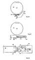
- FIG. 18shows a blade 40 and brake pawl 60 , with an engagement member 252 biased to pivot around a pin toward the blade by a spring 280 .
- a solenoid 266holds the engagement member away from the blade.
- the solenoidincludes a plunger 268 configured to retract into the solenoid when the solenoid is powered, thereby releasing the engagement member to engage the blade.
- engagement member 252includes a long lever arm 282 so that plunger 268 and solenoid 266 can hold spring 280 with little force.
- a linkage to provide additional mechanical advantagesuch as the linkage described above in connection with FIGS. 3-10 , could be used to further minimize the force on the plunger from the spring.
- FIG. 19shows a similar embodiment.
- FIG. 20shows an embodiment that includes a loop or leaf spring 290 mounted to a brake pawl 60 .
- the loop springis biased to move toward blade 40 , but is held back by a solenoid 266 and plunger 268 .
- the plungerretracts, the loop moves toward the blade under its own spring force and catches on the teeth of the blade to pull the brake pawl into the blade.
- FIG. 21A side view of another embodiment that uses a solenoid to release a brake pawl is shown in FIG. 21 , and a simplified bottom view of the pawl and release is shown in FIG. 22 .
- This embodimentincludes a brake pawl 60 that is spring-biased to move into blade 40 to stop the blade. However, the brake pawl is restrained from movement by two levers 292 and 294 . Those levers engage two pockets 296 and 298 , respectively, on the brake pawl to prevent the brake pawl from moving.
- Levers 292 and 294are mounted in a housing 300 on pivot pins 302 and 304 , respectively.
- a spring 306mounted in the housing, tends to push the levers apart, as indicated by arrows.
- a solenoid 266 and plunger 268are positioned adjacent the ends of the levers opposite the brake pawl, and the plunger extends between the levers to prevent them from pivoting.
- the solenoidis configured to retract the plunger, and when it does, the levers are free, so spring 306 then causes the levers to pivot, thereby releasing the brake pawl to move into the blade.
- Housing 300is configured with slots to allow the levers to pivot outwardly to release the brake pawl. Bearings may be placed on the ends of the levers to allow the solenoid to more easily retract the plunger. This embodiment could be modified so that only one lever is used to prevent the brake pawl from moving.
- the leversmay be vertically offset from each other to provide clearance.
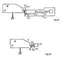
- FIG. 23Another embodiment is shown in FIG. 23 . It includes a brake pawl 60 with a spring to push the brake pawl into a blade.
- the brake pawlis restrained from movement by a first lever 310 mounted in a housing 312 to pivot around a pin 314 .
- First lever 310includes an end 316 that fits through a slot in the housing and that engages the brake pawl, as shown.
- a second lever 318 mounted in the housingrestrains the first lever, and a solenoid and plunger, also mounted in the housing, restrain the second lever. When the solenoid is actuated, the plunger retracts into the solenoid, allowing the levers to pivot and the brake pawl to engage the blade.
- the leversmay be shaped in many different forms, and are shown in FIG. 23 as step-shaped to provide a compact assembly.
- FIG. 24Another simple embodiment is shown in FIG. 24 . It includes a solenoid 266 with a plunger 268 .
- the plungeris positioned to engage a shoulder 320 of a brake pawl 60 to prevent the brake pawl from moving into a blade.
- a strong springcould be used to push the brake pawl toward the blade quickly.
- a strong springwould create substantial friction on the plunger.
- a first roller bearing 322is placed on the shoulder of the brake pawl to allow the plunger to slide off the shoulder when the solenoid retracts the plunger, and a second bearing 324 is positioned to support the plunger.
- the safety systems and actuators described hereinare applicable to power equipment, and specifically to power equipment wherein some action is triggered or released.
- the safety systems and actuatorsare particularly applicable to woodworking equipment such as table saws, miter saws, band saws, circular saws, jointers, etc.
- the safety systems and actuators described hereinmay be adapted for use on a variety of other saws and machines, and further descriptions may be found in the following references, the disclosures of which are herein incorporated by reference: PCT Patent Application Serial No. PCT/US00/26812, filed Sep. 29, 2000; U.S. patent application Ser. No. 09/676,190, filed Sep. 29, 2000; U.S. Provisional Patent Application Ser. No. 60/306,202, filed Jul. 18, 2001; U.S.
Landscapes
- Engineering & Computer Science (AREA)
- Mechanical Engineering (AREA)
- General Engineering & Computer Science (AREA)
- Life Sciences & Earth Sciences (AREA)
- Wood Science & Technology (AREA)
- Forests & Forestry (AREA)
- Sawing (AREA)
Abstract
Description
This application claims the benefit of and priority from the following U.S. Provisional Patent Application, the disclosure of which is herein incorporated by reference: Ser. No. 60/307,756, filed Jul. 25, 2001.
The invention relates to safety systems and more particularly to actuators for use in high-speed safety systems for power equipment.
Safety systems are often employed with power equipment such as table saws, miter saws and other woodworking machinery, to minimize the risk of injury when using the equipment. Probably the most common safety feature is a guard that physically blocks an operator from making contact with dangerous components of machinery, such as belts, shafts or blades. In many cases, guards effectively reduce the risk of injury, however, there are many instances where the nature of the operations to be performed precludes using a guard that completely blocks access to hazardous machine parts.
Other safety systems try to prevent or minimize injury by detecting and reacting to an event. For instance, U.S. Pat. Nos. 3,953,770, 4,075,961, 4,470,046, 4,532,501 and 5,212,621, the disclosures of which are incorporated herein by reference, disclose radio-frequency safety systems which utilize radio-frequency signals to detect the presence of a user's hand in a dangerous area of the machine and thereupon prevent or interrupt operation of the machine. U.S. Pat. Nos. 3,785,230 and 4,026,177, the disclosures of which are herein incorporated by reference, disclose a safety system for use on circular saws to stop the blade when a user's hand approaches the blade. The system uses the blade as an antenna in an electromagnetic proximity detector to detect the approach of a user's hand prior to actual contact with the blade. Upon detection of a user's hand, the system engages a brake using a standard solenoid. Unfortunately, such a system is prone to false triggers and is relatively slow acting because of the solenoid and the way the solenoid is used.
U.S. Pat. No. 4,117,752, which is herein incorporated by reference, discloses a braking system for use with a band saw, where the brake is triggered by actual contact between the user's hand and the blade. However, the system described for detecting blade contact does not appear to be functional to accurately and reliably detect contact. Furthermore, the system relies on standard electromagnetic brakes operating off of line voltage to stop the blade and pulleys of the band saw. It is believed that such brakes would take 50 milliseconds to 1 second to stop the blade. Therefore, the system is too slow to stop the blade quickly enough to avoid serious injury.
None of these existing systems have operated with sufficient speed and/or reliability to prevent serious injury with many types of commonly used power tools.
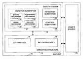
A machine that may incorporate a firing subsystem according to the present invention is shown schematically in FIG.1 and indicated generally at10.Machine 10 may be any of a variety of different machines adapted for cutting workpieces, such as wood, including a table saw, miter saw (chop saw), radial arm saw, circular saw, band saw, jointer, planer, up-cut saw, etc.Machine 10 includes anoperative structure 12 having acutting tool 14 and amotor assembly 16 adapted to drive the cutting tool.Machine 10 also includes asafety system 18 configured to minimize the potential of a serious injury to aperson using machine 10.Safety system 18 is adapted to detect the occurrence of one or more dangerous conditions during use ofmachine 10. If such a dangerous condition is detected,safety system 18 is adapted to engageoperative structure 12 to limit any injury to the user caused by the dangerous condition.
It will be appreciated thatoperative structure 12 may take any one of many different forms, depending on the type ofmachine 10. For example,operative structure 12 may include a stationary housing configured to supportmotor assembly 16 in driving engagement withcutting tool 14. Alternatively,operative structure 12 may include a movable structure configured to carrycutting tool 14 between multiple operating positions. As a further alternative,operative structure 12 may include one or more transport mechanisms adapted to convey a workpiece toward and/or away fromcutting tool 14.
Once activated in response to a dangerous condition,reaction subsystem 24 is configured to engageoperative structure 12 quickly to prevent serious injury to the user. It will be appreciated that the particular action to be taken byreaction subsystem 24 will vary depending on the type ofmachine 10 and/or the dangerous condition that is detected. For example,reaction subsystem 24 may be configured to do one or more of the following: stop the movement of cuttingtool 14,disconnect motor assembly 16 frompower source 20, place a barrier between the cutting tool and the user, or retract the cutting tool from its operating position, etc. The reaction subsystem may be configured to take a combination of steps to protect the user from serious injury. Placement of a barrier between the cutting tool and a person is described in more detail in U.S. Provisional Patent Application Ser. No. 60/225,206, entitled “Cutting Tool Safety System,” filed Aug. 14, 2000 by SD3, LLC, the disclosure of which is herein incorporated by reference. Retraction of the cutting tool from its operating position is described in more detail in U.S. Provisional Patent Application Ser. No. 60/225,089, entitled “Retraction System For Use In Power Equipment,” also filed Aug. 14, 2000 by SD3, LLC, the disclosure of which is herein incorporated by reference.
The configuration ofreaction subsystem 24 typically will vary depending on which action(s) are taken. In the exemplary embodiment depicted inFIG. 1 ,reaction subsystem 24 is configured to stop the movement of cuttingtool 14 and includes abrake mechanism 28, abiasing mechanism 30, a restrainingmechanism 32, and arelease mechanism 34.Brake mechanism 28 is adapted to engageoperative structure 12 under the urging of biasingmechanism 30. During normal operation ofmachine 10, restrainingmechanism 32 holds the brake mechanism out of engagement with the operative structure. However, upon receipt of an activation signal byreaction subsystem 24, the brake mechanism is released from the restraining mechanism byrelease mechanism 34, whereupon, the brake mechanism quickly engages at least a portion of the operative structure to bring the cutting tool to a stop.
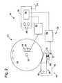
It will be appreciated by those of skill in the art that the exemplary embodiment depicted in FIG.1 and described above may be implemented in a variety of ways depending on the type and configuration ofoperative structure 12. Turning attention toFIG. 2 , one example of the many possible implementations ofsafety system 18 is shown.System 18 is configured to engage an operative structure having a cutting tool in the form of acircular blade 40 mounted on a rotating shaft orarbor 42.Blade 40 includes a plurality of cutting teeth (not shown) disposed around the outer edge of the blade. As described in more detail below,braking mechanism 28 is adapted to engage the teeth ofblade 40 and stop the rotation of the blade. U.S. Provisional Patent Application Ser. No. 60/225,210, entitled “Translation Stop For Use In Power Equipment,” filed Aug. 14, 2000 by SD3, LLC, the disclosure of which is herein incorporated by reference, describes other systems for stopping the movement of the cutting tool. U.S. Provisional Patent Application Ser. No. 60/225,058, entitled “Table Saw With Improved Safety System,” filed Aug. 14, 2000 by SD3, LLC, and U.S. Provisional Patent Application Ser. No. 60/225,057, entitled “Miter Saw With Improved Safety System,” filed Aug. 14, 2000 by SD3, LLC, the disclosures of which are herein incorporated by reference, describesafety system 18 in the context of particular types ofmachines 10.
In the exemplary implementation,detection subsystem 22 is adapted to detect the dangerous condition of the user coming into contact withblade 40. The detection subsystem includes a sensor assembly, such ascontact detection plates blade 40 to detect any contact between the user's body and the blade. Typically, the blade, or some larger portion of cuttingtool 14 is electrically isolated from the remainder ofmachine 10. Alternatively,detection subsystem 22 may include a different sensor assembly configured to detect contact in other ways, such as optically, resistively, etc. In any event, the detection subsystem is adapted to transmit a signal to controlsubsystem 26 when contact between the user and the blade is detected. Various exemplary embodiments and implementations ofdetection subsystem 22 are described in more detail in U.S. Provisional Patent Application Ser. No. 60/225,200, entitled “Contact Detection System For Power Equipment,” filed Aug. 14, 2000 by SD3, LLC, and U.S. Provisional Patent Application Ser. No. 60/225,211, entitled “Apparatus And Method For Detecting Dangerous Conditions In Power Equipment,” filed Aug. 14, 2000 by SD3, LLC, the disclosures of which are herein incorporated by reference.
In the exemplary implementation,brake mechanism 28 includes apawl 60 mounted adjacent the edge ofblade 40 and selectively moveable to engage and grip the teeth of the blade.Pawl 60 may be constructed of any suitable material adapted to engage and stop the blade. As one example, the pawl may be constructed of a relatively high strength thermoplastic material such as polycarbonate, ultrahigh molecular weight polyethylene (UHMW) or Acrylonitrile Butadiene Styrene (ABS), etc., or a metal such as aluminum, etc. It will be appreciated that the construction ofpawl 60 will vary depending on the configuration ofblade 40. In any event, the pawl is urged into the blade by a biasing mechanism in the form of aspring 66. In the illustrative embodiment shown inFIG. 2 ,pawl 60 is pivoted into the teeth ofblade 40. It should be understood that sliding or rotary movement ofpawl 60 might also be used. The spring is adapted to urgepawl 60 into the teeth of the blade with sufficient force to grip the blade and quickly bring it to a stop.
A restrainingmechanism 70 holds the pawl away from the edge of the blade. The restraining member may take different forms. For example, in some embodiments the restraining member is a fusible member. The fusible member is constructed of a suitable material and adapted to restrain the pawl against the bias ofspring 66, and also adapted to melt under a determined electrical current density to release the pawl. Various exemplary embodiments and implementations of restraining members and fusible members are described in more detail in U.S. Provisional Patent Application Ser. No. 60/225,056, entitled “Firing Subsystem for use in a Fast-Acting Safety System,” filed Aug. 14, 2000 by SD3, LLC, the disclosure of which is herein incorporated by reference. In other embodiments, the restraining member may include various mechanical linkages, or may be part of various actuators, and those linkages and/or actuators may be released or fired by solenoids, gas cylinders, electromagnets, and/or explosives. Preferably, restrainingmember 70 holds the pawl relatively close to the edge of the blade to reduce the distance the pawl must travel to engage the blade. Positioning the pawl relatively close to the edge of the blade reduces the time required for the pawl to engage and stop the blade. Typically, the pawl is held approximately 1/32-inch to ¼-inch from the edge of the blade by restrainingmember 70, however other pawl-to-blade spacings may also be used within the scope of the invention.
It will be appreciated that activation of the brake mechanism will require the replacement of one or more portions ofsafety system 18. For example,pawl 60 and restrainingmember 70 typically must be replaced before the safety system is ready to be used again. Thus, it may be desirable to construct one or more portions ofsafety system 18 in a cartridge that can be easily replaced. For example, in the exemplary implementation depicted inFIG. 2 ,safety system 18 includes areplaceable cartridge 80 having ahousing 82.Pawl 60,spring 66, restrainingmember 70 are all mounted withinhousing 82. Alternatively, other portions ofsafety system 18 may be mounted within the housing. In any event, after the reaction system has been activated, the safety system can be reset by replacingcartridge 80. The portions ofsafety system 18 not mounted within the cartridge may be replaced separately or reused as appropriate. Various exemplary embodiments and implementations of a safety system using a replaceable cartridge are described in more detail in U.S. Provisional Patent Application Ser. No. 60/225,201, entitled “Replaceable Brake Mechanism For Power Equipment,” filed Aug. 14, 2000 by SD3, LLC, and U.S. Provisional Patent Application Ser. No. 60/225,212, entitled “Brake Positioning System,” filed Aug. 14, 2000 by SD3, LLC, the disclosures of which are herein incorporated by reference.
While one particular implementation ofsafety system 18 has been described, it will be appreciated that many variations and modifications are possible within the scope of the invention. Many such variations and modifications are described in U.S. Provisional Patent Application Ser. No. 60/157,340, entitled “Fast-Acting Safety Stop,” filed Oct. 1, 1999, and Ser. No. 60/182,866, also entitled “Fast-Acting Safety Stop,” filed Feb. 16, 2000, the disclosures of which are herein incorporated by reference.
As explained above, in some embodiments ofsafety system 18, a restrainingmember 70 is used to restrain some element or action, such as to hold a brake or pawl away from a blade. Such a restraining member may take different forms. For example, it may be an actuator or part of an actuator that applies a force to move a brake pawl into a blade. One possible embodiment of such an actuator is shown at99 inFIGS. 3 and 4 .
The depicted embodiment includes asolenoid 100 mounted in ahousing 102.Solenoid 100 includes a wire helically coiled around a tube or cylinder. A metal core or plunger, often taking the form of a rod, is positioned adjacent the cylinder at least partially within the coiled wire. The solenoid creates a magnetic field when electric current flows through the coiled wire, and the magnetic field then causes the plunger to move, typically drawing the plunger into the cylinder. The plunger is often spring-biased out from the cylinder so that it extends from the cylinder when there is no current flowing through the coil, and then is drawn in when current is flowing through the coil. Thus, solenoids are used to move a plunger in and out depending on whether electricity flows through the coil. The in-and-out movement of the plunger can be used to trigger or cause some action to take place. The solenoid may be powered by firingcircuit 76.
In the embodiment shown inFIGS. 3 and 4 , aplunger 104 extends outwardly fromsolenoid 100. A spring or some other biasing means biases plunger104 outwardly from the solenoid, and the plunger is drawn into the solenoid when current flows through the solenoid. The embodiment shown inFIGS. 3 and 4 uses the movement ofplunger 104 to releasebrake pawl 60 to stop the blade of a saw, as described above.
The end ofplunger 104 that extends outwardly fromsolenoid 100 passes into anaperture 106 in afirst pivot arm 108.First pivot arm 108 may take many different forms. InFIGS. 3 and 4 ,first pivot arm 108 is made from a flat piece of metal, as shown inFIG. 5 , and it includes ends112 and114, and first andsecond wing portions cut 120 is made between the wing portions and end116. The wings and end118 are then folded together into something like a “W” shape when viewed fromend 118, as shown in FIG.6. Cut120 allows for the center section to be folded into the “W” shape. When folded, the wings provide rigidity and ends116 and118 extend outwardly, as shown inFIG. 3. A pivot pin 122 is supported byhousing 102, andfirst pivot arm 108 is mounted to pivot aroundpivot pin 122.Pivot pin 122 extends throughapertures wings plunger 104 extends intoaperture 106 infirst pivot arm 108 and thereby prevents the first pivot arm from pivoting.
When electric current is applied tosolenoid 100,plunger 104 is retracted, allowing the first pivot arm to pivot aroundpin 122. When the first pivot arm is released, the second pivot arm and plate are also released and free to move.Spring 162 then forcesplate 150 to move in the direction ofarrow 170, and the first and second pivot arms pivot as shown in FIG.10.Aperture 152 inplate 150 is sized and shaped to allowend 132 of the second pivot arm to move out of the aperture as the plate is pulled in the direction ofarrow 170.Housing 102 is sized to provide the space necessary for the pivot arms to pivot sufficiently to releaseplate 150.
Thus,actuator 99 provides a mechanism that releases a force by using a solenoid. The force is then used to move a brake pawl into the teeth of a spinning saw blade, as explained above.Solenoid 100 must be sufficiently strong to overcome the friction betweenplunger 104 andaperture 106 caused byspring 162 putting tension on the parts of the actuator. Otherwise, the solenoid could not retractplunger 104. Often, as stated, a very strong spring is used to push the brake pawl into the saw blade as quickly as possible. However, the stronger the spring, the more tension on the system and the more friction between the plunger and the aperture.Actuator 99 accommodates strong springs by using multiple pivot arms. For example, the two pivot arms described above provide the mechanical advantage necessary to hold a strong spring. Two or more pivot arms are used to gain the advantage of multiple pivot points, rather than using a single pivot point with a longer moment arm. However, a single pivot arm may be used in some embodiments. In the embodiment shown inFIGS. 3 and 4 , a solenoid that can retract a plunger with a force of approximately 50 grams can hold a spring force of around 100 Newtons, considering thatfirst pivot arm 108 provides a mechanical advantage of a factor of 3 to 4, andsecond pivot arm 130 provides a mechanical advantage of a factor of around 6, and the solenoid would need to provide a retraction force to overcome the friction on the plunger of approximately 1/10thof the force on the plunger from the spring. Of course, the pivot arms can be sized differently to provide the mechanical advantage necessary for different springs, or different numbers of pivot arms can be used. One significant advantage of using a mechanical linkage like the two pivot arms discussed above, is thatactuator 99 may use a solenoid that is physically small and relatively inexpensive to release the spring, resulting in an actuator that is effective, economical, and sized so that it is applicable to various types of saws.
Another significant benefit of the actuator shown inFIGS. 3 and 4 is that it completely releases a significant force with only a short, discrete movement ofplunger 104. The plunger need only retract a specified and determined amount to disengage withfirst pivot arm 108, and the entire force ofspring 162 is released. Thus, the speed at which the actuator can apply a force is maximized because time is not spent by the solenoid moving the plunger a significant distance. That results in being able to stop the blade of the saw quicker that otherwise would be possible, and stopping the blade as quickly as possible minimizes any injury to a person accidentally contacting the blade.
The solenoid also must be sufficiently strong to overcome the spring or other means that biases plunger104 outwardly. The solenoid also must release the force quickly enough so that the brake can engage and stop the saw blade before a person who accidentally contacts the blade receives a serious injury under typical circumstances. The necessary release time will depend on the embodiment, but will usually not exceed around 5 milliseconds. Of course, the shorter the release time the better.
Another embodiment of an actuator uses a shape memory alloy, such as a Nitinol (nickel-titanium) actuator wire or CuAlNi or TiNiPd alloys, to provide a movement to release a force. Shape memory alloys contract when heated through a phase-change transition temperature, and can be restretched as they cool to ambient temperatures. For example, a Nitinol wire with a diameter of 0.010-inch and a maximum pull force of 930-grams may have a transition temperature of 70-90 degrees Celsius.
One embodiment using a shape memory alloy is shown inFIG. 12 , and it includes anactuator wire 210 connected to firing circuit76 (which constitutes a source of electricity to heat the shape memory alloy) and to apin 212.Pin 212 engages a first pivot arm and restrains that pivot arm from moving, just asplunger 104 restrainspivot arm 108 in the embodiment disclosed above in connection withFIGS. 3 and 4 .Pin 212 is mounted in the housing of the actuator so that it can pivot away from the pivot arm to release the arm, and also so that it can prevent the pivot arm from moving while the pin is engaged with the pivot arm, as shown inFIG. 13. A hinge joint 214 allowspin 212 to pivot. The hinge joint can be constructed tobias pin 212 toward the first pivot arm to help insure that the pin remains engaged with the pivot arm until pulled bywire 210. When electric current from firingcircuit 76 flows throughwire 210, the resistance of the wire heats the wire and causes the wire to contract, which pullspin 212 free from the first pivot arm, releasing the spring force as described above.
By way of example, shape memory actuator wires made of nickel-titanium and marketed by Dynalloy, Inc. under the trade name Flexinol may be used. A Flexinol wire having a diameter of approximately 0.01-inch and a resistance of 0.5-ohms per inch could provide approximately 930 grams of pull force, with an approximate current of 1000-milliamps and with a contraction of 4% of length over 1 second, where the contraction time is related to current input. A linear actuator marketed by NanoMuscle, Inc. of Antioch, Calif. under the trade name “NanoMuscle” is another example of a shape memory actuator that may be used.
In the safety systems described above, it is desirable that the shape memory alloy contract quickly in order to release a reaction system quickly. In those safety systems, the shape memory alloy typically needs to contract within 5 milliseconds of detecting a dangerous condition, and preferably within 1 millisecond. A large current pulse may be applied to the shape memory alloy to cause the alloy to contract in that timeframe. The amount of current to be applied will depend on several factors, including but not limited to the resistance of the wire, the length and volume of the wire, the heat capacity of the wire, etc.
By way of example, consider a 50-millimeter long Nitinol wire, cylindrically shaped with a diameter of 0.25 millimeters. Assume the heat capacity “Cp” of Nitinol is 0.077-calories per gram per degree Celsius, and the density “d” of Nitinol is 6.45-grams per cubic centimeter. The volume “V” of the wire is equal to the following:
V=πr2l=(3.14)(0.000125 m)2(0.05m)=2.45×10⁻⁹ m3=2.45×10⁻³cm3
The mass “m” of the wire is as follows:
m=Vd=(2.45×10⁻³cm3)(6.45 gm/cm3)=0.0158 gm
Assuming the wire is at an ambient room temperature of approximately 20-degrees Celsius, and further assuming that the phase-change temperature of the wire is 70- to 90-degree Celsius, then the wire should be heated to a temperature of approximately 100-degree Celsius to ensure that the wire is heated through its phase-change transition temperature. Thus, the wire must be heated approximately 80-degrees Celsius, which is represented by “T.” The energy “E” required to heat the wire that amount is given by:
E=m CpT=(0.0158 gm)(0.077 cal/gm-C. °)(80 C. °)=0.1 cal≈0.5 Joules.
This energy must be supplied quickly, for example within 1- to 5-milliseconds, so that the wire reacts with the desired speed. A charge storage device, such as a capacitor, and a gate device, such as a silicon controlled rectifier or SCR, may be used to provide this energy. The capacitor would store the energy and the SCR would gate that energy to ground through the wire. Many different capacitors may be used. For example, the energy “U” stored by capacitors is given the formula U=½ CV2, where “C” is the capacitance and “V” is the voltage of the capacitor. Selecting a voltage of 100-volts, and requiring 0.5-Joules of energy, results in the following capacitance:
C=2U/V2=(2)(0.5-Joules)/(100-volts)2=100-microfarads.
Thus, a 100-microfarad, 100-volt capacitor would store 0.5-Joules of energy. Capacitors discharge approximately 67% of their stored energy in the time given by the equation t=RC, where “t” is the time, C is the capacitance, and R is the resistance. Following that equation, the 100-microfarad capacitor discussed above would discharge 67% of its energy in 100 microseconds, assuming a resistance of 1-ohm. Essentially all of the energy stored in the capacitor would be released within 5-milliseconds. Of course, as is evident from the above discussion, various capacitors may be selected to supply the necessary energy in the desired time.
Advantages of using a shape memory alloy include the relatively small size of an actuator, ease of use, low power consumption, and the relative low cost of the material. The retraction force and stroke can also be readily determined and selected. This embodiment has particular application to inexpensive hand-held circular saws, and other less expensive saws, because of the low cost and small size of shape memory alloys.
Some embodiments also may use integrated force arrays instead of solenoids or voice coil actuators to create the motion to release the force. Integrated force arrays are flexible metalized membranes that undergo deformation when voltage is applied to them. An integrated force array resembles a thin, flexible membrane, and it contracts by around 30% in one dimension when voltage is applied to it. An integrated force array may be configured to provide substantial force.
An advantage of actuators using solenoids, voice coil actuators, shape memory alloys, or integrated force arrays, is that they may be configured for multiple uses. After a movement is produced to release a force, the actuator may be “re-cocked” by compressing the spring or recreating the force, repositioning the mechanical linkage holding the force, and then reinserting a pin to restrain the linkage. Additionally, the advantages described above relating to solenoids, such a releasing a force with a short, discrete stroke, are also applicable to voice coil actuators, shape memory alloys, and integrated force arrays.
The solenoids, voice coil actuators, shape memory alloys and integrated force arrays discussed above can be connected to firingsystem 76 to produce the necessary electric current. As will be appreciated by those of skill in the art, there are many circuits suitable for supplying this current. A typical circuit would include one or more charge storage devices that are discharged in response to an output signal from the control subsystem. (The output signal from the control subsystem is dependant on detection of a dangerous condition between a person and a blade, such as contact, as explained above.) It will be appreciated, however, that a current supply may be used instead of charge storage devices. Alternatively, other devices may be used to supply the necessary current, including a silicon-controlled rectifier (SCR) or triac connected to a power supply line. Transistors and/or SCRs may be used to release the charge in the charge storage devices upon a signal from the control subsystem.
Another embodiment of an actuation system is shown inFIGS. 14 through 16 . That embodiment includes an engagement member that moves into a spinning blade. The engagement member is attached to a brake pawl so that when the engagement member contacts the blade, the blade and engagement member pull the brake pawl into the blade to stop the blade. The engagement member is small and light so that it can be easily and quickly moved into the blade. This embodiment uses the force of the blade to move a brake pawl into the blade, instead of using a spring or some other item to move the brake pawl. The engagement member may be thought of as a pilot pawl that leads the brake pawl into the blade. The brake may be thought of as direct-acting because the force of the blade directly causes the brake to engage the blade.
Anengagement member 252 is mounted to brakepawl 60 by apivot pin 254.Engagement member 252 is positionedadjacent blade 40 so that it can pivot aroundpin 254 into the teeth of the blade.FIG. 15 shows a simplified end-view ofbrake pawl 60 andengagement member 252 withpivot pin 254, andFIG. 16 shows an enlarged view of the brake pawl and engagement member.Engagement member 252 includes twoarms post 260 onbrake pawl 60.Pivot pin 254 passes through an aperture in the two arms and post to mount the engagement member to the brake pawl. Brake pawl includes a recessedarea 262 shaped to accommodateengagement member 252.Brake pawl 60 also includes ashoulder 264 against whichengagement member 252 abuts to prevent the engagement member from pivoting in a direction away fromblade 40. Of course, the brake pawl and engagement member may be configured and connected in many different ways, and the illustrated embodiment is intended as only one example.
Asmall solenoid 266 is mounted onbrake pawl 60, and aplunger 268 extends from the solenoid.Solenoid 266 is configured to causeplunger 268 to extend out when electricity is applied to the solenoid. The solenoid may be any one of various types of solenoids, but typically would be a small, light-weight solenoid, such as those found in some simple ground-fault-interrupt switches and circuit breakers.Solenoid 268 may be powered by firingsystem 76, as described above. InFIGS. 14-16 ,solenoid 266 is shown mounted to a surface of the brake pawl. The solenoid could be mounted adjacent the brake pawl in many ways, such as by screws, or the brake pawl could include a recess adapted to receive and hold the solenoid.Plunger 268 extends fromsolenoid 266 andcontacts engagement member 252. In the depicted embodiment,plunger 268 abuts aflange 270 on the engagement member.
When firingsystem 76 powers solenoid266, the solenoid causesplunger 268 to extend. The plunger, in turn, then pushes againstflange 270 onengagement member 252, causing the engagement member to pivot aroundpin 254 into the blade. The teeth of the blade then strike the engagement member and cause the engagement member to move in the direction the blade is spinning. That movement then causesbrake pawl 60 to pivot aroundpin 250 into the teeth of the blade. The blade cuts into the brake pawl and stops, as described above.
As stated, the engagement member is small and light so that little force is required to move it into engagement with the blade. The engagement member may be made of ABS plastic, for example, and have a mass small enough that an inexpensive solenoid would provide sufficient force to move the engagement member into contact with the blade quickly.
As shown inFIG. 14 , a small wire or spring270 (shown in dashed lines) may be used to hold the brake pawl away from the blade during normal use of the saw. The wire or spring would be configured to break or stretch, respectively, when the engagement member contacts the blade and the blade draws the brake pawl in. Alternatively,engagement member 252 may include apin 272, shown inFIG. 16 , that slides in achannel 274.Channel 274 is separate from and stationary relative to the brake pawl, and may be part of a housing or frame adjacent the brake pawl. The geometry ofchannel 274 is shaped so thatpin 272 slides freely in the channel when the engagement member pivots aroundpin 254, but pin272 cannot slide in the channel whenbrake pawl 60 tries to pivot aroundpin 250. In this manner, the brake pawl is prevented from pivoting toward the blade until the engagement member pivots out and pin272 clearschannel 274.FIG. 14 also shows that astop 276 that may be positioned adjacent the brake pawl to prevent the brake pawl from pivoting away from the blade.
Systems that use a solenoid to move an engagement member or pilot pawl may take many different forms.FIG. 17 shows ablade 40 with abrake pawl 60 adjacent the blade. Asolenoid 266 is mounted on the brake pawl, and configured to push anengagement member 252 down into the teeth of the blade. The teeth of the blade then catch on the engagement member and pull the brake pawl into the blade. The engagement member may take many forms, such as a “U” shaped member configured to loop over the teeth of the blade, wire, Kevlar or fabric mesh configured to snag the teeth of the blade, or simply material into which the teeth of the blade can cut.
A side view of another embodiment that uses a solenoid to release a brake pawl is shown inFIG. 21 , and a simplified bottom view of the pawl and release is shown in FIG.22. This embodiment includes abrake pawl 60 that is spring-biased to move intoblade 40 to stop the blade. However, the brake pawl is restrained from movement by twolevers pockets Levers housing 300 onpivot pins spring 306, mounted in the housing, tends to push the levers apart, as indicated by arrows. Asolenoid 266 andplunger 268 are positioned adjacent the ends of the levers opposite the brake pawl, and the plunger extends between the levers to prevent them from pivoting. The solenoid is configured to retract the plunger, and when it does, the levers are free, sospring 306 then causes the levers to pivot, thereby releasing the brake pawl to move into the blade.Housing 300 is configured with slots to allow the levers to pivot outwardly to release the brake pawl. Bearings may be placed on the ends of the levers to allow the solenoid to more easily retract the plunger. This embodiment could be modified so that only one lever is used to prevent the brake pawl from moving. The levers may be vertically offset from each other to provide clearance.
Another embodiment is shown in FIG.23. It includes abrake pawl 60 with a spring to push the brake pawl into a blade. The brake pawl is restrained from movement by afirst lever 310 mounted in ahousing 312 to pivot around apin 314.First lever 310 includes anend 316 that fits through a slot in the housing and that engages the brake pawl, as shown. Asecond lever 318 mounted in the housing restrains the first lever, and a solenoid and plunger, also mounted in the housing, restrain the second lever. When the solenoid is actuated, the plunger retracts into the solenoid, allowing the levers to pivot and the brake pawl to engage the blade. The levers may be shaped in many different forms, and are shown inFIG. 23 as step-shaped to provide a compact assembly.
Another simple embodiment is shown in FIG.24. It includes asolenoid 266 with aplunger 268. The plunger is positioned to engage ashoulder 320 of abrake pawl 60 to prevent the brake pawl from moving into a blade. As explained above, a strong spring could be used to push the brake pawl toward the blade quickly. However, a strong spring would create substantial friction on the plunger. Accordingly, afirst roller bearing 322 is placed on the shoulder of the brake pawl to allow the plunger to slide off the shoulder when the solenoid retracts the plunger, and asecond bearing 324 is positioned to support the plunger.
It will be appreciated by those of skill in the applicable arts that any suitable embodiment or configuration of the actuators discussed generally above could be used. The control systems, power supplies, sense lines and other items related to or used with actuators are discussed in more detail in U.S. Provisional Patent Application Ser. No. 60/225,200, titled “Contact Detection System for Power Equipment,” U.S. Provisional Patent Application Ser. No. 60/225,211, titled “Apparatus and Method for Detecting Dangerous Conditions in Power Equipment,” and U.S. Provisional Patent Application Ser. No. 60/225,059, titled “Logic Control for Fast-Acting Safety System,” all filed Aug. 14, 2000, the disclosures of which are herein incorporated by reference.
The safety systems and actuators described herein are applicable to power equipment, and specifically to power equipment wherein some action is triggered or released. The safety systems and actuators are particularly applicable to woodworking equipment such as table saws, miter saws, band saws, circular saws, jointers, etc. The safety systems and actuators described herein may be adapted for use on a variety of other saws and machines, and further descriptions may be found in the following references, the disclosures of which are herein incorporated by reference: PCT Patent Application Serial No. PCT/US00/26812, filed Sep. 29, 2000; U.S. patent application Ser. No. 09/676,190, filed Sep. 29, 2000; U.S. Provisional Patent Application Ser. No. 60/306,202, filed Jul. 18, 2001; U.S. Provisional Patent Application Ser. No. 60/302,916, filed Jul. 3, 2001; U.S. Provisional Patent Application Ser. No. 60/302,937, filed Jul. 2, 2001; U.S. Provisional Patent Application Ser. No. 60/298,207, filed Jun. 13, 2001; U.S. Provisional Patent Application Ser. No. 60/292,100, filed May 17, 2001; U.S. Provisional Patent Application Ser. No. 60/292,081, filed May 17, 2001; U.S. Provisional Patent Application Ser. No. 60/279,313, filed Mar. 27, 2001; U.S. Provisional Patent Application Ser. No. 60/275,595, filed Mar. 13, 2001; U.S. Provisional Patent Application Ser. No. 60/275,594, filed Mar. 13, 2001; U.S. Provisional Patent Application Ser. No. 60/275,583, filed Mar. 13, 2001; U.S. Provisional Patent Application Ser. No. 60/273,902, filed Mar. 6, 2001; U.S. Provisional Patent Application Ser. No. 60/273,178, filed Mar. 2, 2001; U.S. Provisional Patent Application Ser. No. 60/273,177, filed Mar. 2, 2001; U.S. Provisional Patent Application Ser. No. 60/270,942, filed Feb. 22, 2001; U.S. Provisional Patent Application Ser. No. 60/270,941, filed Feb. 22, 2001; U.S. Provisional Patent Application Ser. No. 60/270,011, filed Feb. 20, 2001; U.S. Provisional Patent Application Ser. No. 60/233,459, filed Sep. 18, 2000; U.S. Provisional Patent Application Ser. No. 60/225,212, filed Aug. 14, 2000; and U.S. Provisional Patent Application Ser. No. 60/225,201, filed Aug. 14, 2000.
It is believed that the disclosure set forth above encompasses multiple distinct inventions with independent utility. While each of these inventions has been disclosed in its preferred form, the specific embodiments thereof as disclosed and illustrated herein are not to be considered in a limiting sense as numerous variations are possible. The subject matter of the inventions includes all novel and non-obvious combinations and subcombinations of the various elements, features, functions and/or properties disclosed herein. No single feature, function, element or property of the disclosed embodiments is essential to all of the disclosed inventions.
Claims (14)
1. An actuator for use in a safety system for a power tool, where the power tool includes a moving blade, the actuator comprising:
an engagement member adapted to move into contact with the moving blade,
a brake pawl attached to the engagement member so that when the engagement member contacts the moving blade, the blade and engagement member pull the brake pawl into the blade, and
a mechanism adapted to cause the engagement member to move into contact with the blade prior to the blade and engagement member pulling the brake pawl into the blade.
2.The actuator ofclaim 1 , where the mechanism adapted to cause the engagement member to move into contact with the moving blade includes a splenoid.
3.The actuator ofclaim 1 , where the mechanism adapted to cause the engagement member to move into contact with the moving blade includes a shape memory alloy.
4. The actuator ofclaim 1 , where the mechanism adapted to cause the engagement member to move into contact with the moving blade includes a voice coil.
5. The actuator ofclaim 1 , where the mechanism adapted to cause the engagement member to move into contact with the moving blade includes an integrated force array.
6. The actuator ofclaim 1 , where the engagement member is pivotally attached to the brake pawl.
7. The actuator ofclaim 1 , further comprising a restraint mechanism to hold the brake pawl away from the blade during normal use of the power tool.
8. The actuator ofclaim 1 , where the engagement member comprises a U-shaped member.
9. The actuator ofclaim 1 , where the engagement member comprises a wire.
10. The actuator ofclaim 1 , where the engagement member comprises a mesh.
11. The actuator ofclaim 1 , where the engagement member comprises a leaf spring.
12. The actuator ofclaim 1 , where the engagement member and brake pawl are configured so that the force of the moving blade causes the brake pawl to engage the blade.
13. The actuator ofclaim 1 , where the engagement member is configured to pivot into the blade.
14. The actuator ofclaim 13 , further comprising a source of stored force adapted to bias the engagement member toward the blade.
15. The actuator ofclaim 14 , where the mechanism adapted to cause the engagement member to move into contact with the blade includes a solenoid and plunger positioned to prevent the source of stored force from causing the engagement member to pivot into the blade until the plunger is moved by the solenoid.
16. An actuator for use in a safety system for a power tool, where the power tool includes a moving blade, the actuator comprising:
brake means for contacting and braking the moving blade,
engagement means for moving into contact with the moving blade and for pulling the brake means into contact with the moving blade,
means for causing the engagement means to move into contact with the moving blade prior to the engagement means pulling the brake means into contact with the moving blade.
Priority Applications (18)
| Application Number | Priority Date | Filing Date | Title |
|---|---|---|---|
| US10/205,164US6945149B2 (en) | 2001-07-25 | 2002-07-25 | Actuators for use in fast-acting safety systems |
| US10/984,643US8061245B2 (en) | 2000-09-29 | 2004-11-08 | Safety methods for use in power equipment |
| US11/190,111US7357056B2 (en) | 2000-09-29 | 2005-07-25 | Cutting tool safety system |
| US11/445,548US7347131B2 (en) | 1999-10-01 | 2006-06-02 | Miter saw with improved safety system |
| US11/542,938US20070028733A1 (en) | 1999-10-01 | 2006-10-02 | Safety methods for use in power equipment |
| US12/800,607US7895927B2 (en) | 1999-10-01 | 2010-05-19 | Power equipment with detection and reaction systems |
| US12/806,830US8191450B2 (en) | 2000-08-14 | 2010-08-20 | Power equipment with detection and reaction systems |
| US12/806,836US8196499B2 (en) | 1999-10-01 | 2010-08-20 | Power equipment with detection and reaction systems |
| US12/806,829US9522476B2 (en) | 1999-10-01 | 2010-08-20 | Power equipment with detection and reaction systems |
| US12/807,147US8402869B2 (en) | 1999-10-01 | 2010-08-27 | Brake mechanism for power equipment |
| US12/807,146US8291797B2 (en) | 1999-10-01 | 2010-08-27 | Table saw with improved safety system |
| US13/442,290US8408106B2 (en) | 1999-10-01 | 2012-04-09 | Method of operating power equipment with detection and reaction systems |
| US13/854,270US20170190012A9 (en) | 1999-10-01 | 2013-04-01 | Power equipment with detection and reaction systems |
| US14/720,552US20150273725A1 (en) | 1999-10-01 | 2015-05-22 | Table saws with detection and reaction systems |
| US14/862,571US9925683B2 (en) | 1999-10-01 | 2015-09-23 | Table saws |
| US15/357,928US9969014B2 (en) | 1999-10-01 | 2016-11-21 | Power equipment with detection and reaction systems |
| US15/362,388US9878380B2 (en) | 1999-10-01 | 2016-11-28 | Table saw throat plates and table saws including the same |
| US15/935,395US10335972B2 (en) | 1999-10-01 | 2018-03-26 | Table Saws |
Applications Claiming Priority (2)
| Application Number | Priority Date | Filing Date | Title |
|---|---|---|---|
| US30775601P | 2001-07-25 | 2001-07-25 | |
| US10/205,164US6945149B2 (en) | 2001-07-25 | 2002-07-25 | Actuators for use in fast-acting safety systems |
Related Parent Applications (2)
| Application Number | Title | Priority Date | Filing Date |
|---|---|---|---|
| US10/202,928ContinuationUS7000514B2 (en) | 1999-10-01 | 2002-07-25 | Safety systems for band saws |
| US10/243,042ContinuationUS7197969B2 (en) | 1999-10-01 | 2002-09-13 | Logic control with test mode for fast-acting safety system |
Related Child Applications (7)
| Application Number | Title | Priority Date | Filing Date |
|---|---|---|---|
| US10/052,806ContinuationUS6880440B2 (en) | 1999-10-01 | 2002-01-16 | Miter saw with improved safety system |
| US10/202,928ContinuationUS7000514B2 (en) | 1999-10-01 | 2002-07-25 | Safety systems for band saws |
| US10/215,929ContinuationUS20030037651A1 (en) | 1999-10-01 | 2002-08-09 | Safety systems for power equipment |
| US10/984,643ContinuationUS8061245B2 (en) | 1999-10-01 | 2004-11-08 | Safety methods for use in power equipment |
| US11/190,111ContinuationUS7357056B2 (en) | 1999-10-01 | 2005-07-25 | Cutting tool safety system |
| US11/445,548ContinuationUS7347131B2 (en) | 1999-10-01 | 2006-06-02 | Miter saw with improved safety system |
| US12/800,607ContinuationUS7895927B2 (en) | 1999-10-01 | 2010-05-19 | Power equipment with detection and reaction systems |
Publications (2)
| Publication Number | Publication Date |
|---|---|
| US20030020336A1 US20030020336A1 (en) | 2003-01-30 |
| US6945149B2true US6945149B2 (en) | 2005-09-20 |
Family
ID=26900176
Family Applications (1)
| Application Number | Title | Priority Date | Filing Date |
|---|---|---|---|
| US10/205,164Expired - LifetimeUS6945149B2 (en) | 1999-10-01 | 2002-07-25 | Actuators for use in fast-acting safety systems |
Country Status (1)
| Country | Link |
|---|---|
| US (1) | US6945149B2 (en) |
Cited By (84)
| Publication number | Priority date | Publication date | Assignee | Title |
|---|---|---|---|---|
| US20030140749A1 (en)* | 2002-01-25 | 2003-07-31 | Gass Stephen F. | Brake Pawls for power equipment |
| US20040194594A1 (en)* | 2003-01-31 | 2004-10-07 | Dils Jeffrey M. | Machine safety protection system |
| US7024975B2 (en) | 2000-08-14 | 2006-04-11 | Sd3, Llc | Brake mechanism for power equipment |
| US7077039B2 (en) | 2001-11-13 | 2006-07-18 | Sd3, Llc | Detection system for power equipment |
| US7098800B2 (en) | 2003-03-05 | 2006-08-29 | Sd3, Llc | Retraction system and motor position for use with safety systems for power equipment |
| US7137326B2 (en) | 2000-08-14 | 2006-11-21 | Sd3, Llc | Translation stop for use in power equipment |
| US7171879B2 (en) | 2001-07-02 | 2007-02-06 | Sd3, Llc | Discrete proximity detection system |
| US7197969B2 (en) | 2001-09-24 | 2007-04-03 | Sd3, Llc | Logic control with test mode for fast-acting safety system |
| US7210383B2 (en) | 2000-08-14 | 2007-05-01 | Sd3, Llc | Detection system for power equipment |
| US7225712B2 (en) | 2000-08-14 | 2007-06-05 | Sd3, Llc | Motion detecting system for use in a safety system for power equipment |
| US7228772B2 (en) | 2000-08-14 | 2007-06-12 | Sd3, Llc | Brake positioning system |
| US7231856B2 (en) | 2001-06-13 | 2007-06-19 | Sd3, Llc | Apparatus and method for detecting dangerous conditions in power equipment |
| US7284467B2 (en) | 2000-08-14 | 2007-10-23 | Sd3, Llc | Apparatus and method for detecting dangerous conditions in power equipment |
| US7290472B2 (en) | 2002-01-14 | 2007-11-06 | Sd3, Llc | Miter saw with improved safety system |
| US7350444B2 (en) | 2000-08-14 | 2008-04-01 | Sd3, Llc | Table saw with improved safety system |
| US7350445B2 (en) | 2003-08-20 | 2008-04-01 | Sd3, Llc | Brake cartridge for power equipment |
| US7353737B2 (en) | 2001-08-13 | 2008-04-08 | Sd3, Llc | Miter saw with improved safety system |
| US7357056B2 (en) | 2000-09-29 | 2008-04-15 | Sd3, Llc | Cutting tool safety system |
| US7359174B2 (en) | 2000-08-14 | 2008-04-15 | Sd3, Llc | Motion detecting system for use in a safety system for power equipment |
| US20080245200A1 (en)* | 2005-07-18 | 2008-10-09 | Bladestop Pty Limited | Electric Saw with Operator Protection System |
| US7472634B2 (en) | 2003-08-20 | 2009-01-06 | Sd3, Llc | Woodworking machines with overmolded arbors |
| US7481140B2 (en) | 2005-04-15 | 2009-01-27 | Sd3, Llc | Detection systems for power equipment |
| US7525055B2 (en) | 1999-10-01 | 2009-04-28 | Sd3, Llc | Switch box for power tools with safety systems |
| US7536238B2 (en) | 2003-12-31 | 2009-05-19 | Sd3, Llc | Detection systems for power equipment |
| US7600455B2 (en) | 2000-08-14 | 2009-10-13 | Sd3, Llc | Logic control for fast-acting safety system |
| US7610836B2 (en) | 2000-08-14 | 2009-11-03 | Sd3, Llc | Replaceable brake mechanism for power equipment |
| US7621205B2 (en) | 1999-10-01 | 2009-11-24 | Sd3, Llc | Band saw with safety system |
| US7628101B1 (en) | 2006-03-13 | 2009-12-08 | Power Tool Institute | Pyrotechnic drop mechanism for power tools |
| US7707920B2 (en) | 2003-12-31 | 2010-05-04 | Sd3, Llc | Table saws with safety systems |
| US7784507B2 (en) | 2000-09-29 | 2010-08-31 | Sd3, Llc | Router with improved safety system |
| US20100257743A1 (en)* | 2009-04-08 | 2010-10-14 | Rex George | Systems and Methods for a Chainsaw Safety Device |
| US7827890B2 (en) | 2004-01-29 | 2010-11-09 | Sd3, Llc | Table saws with safety systems and systems to mount and index attachments |
| US7836804B2 (en) | 2003-08-20 | 2010-11-23 | Sd3, Llc | Woodworking machines with overmolded arbors |
| US20110048199A1 (en)* | 2009-08-26 | 2011-03-03 | Robert Bosch Tool Corporation | Table saw riving knife |
| US20110048191A1 (en)* | 2009-08-26 | 2011-03-03 | Credo Technology Corporation | Table saw with swing arm support |
| US20110048194A1 (en)* | 2009-08-26 | 2011-03-03 | Credo Technology Corporation | Table saw with reset mechanism |
| US20110048188A1 (en)* | 2009-08-26 | 2011-03-03 | Credo Technology Corporation | Table saw with actuator module |
| US20110048205A1 (en)* | 2009-08-26 | 2011-03-03 | Credo Technology Corporation | Table saw with dust shield |
| US20110048195A1 (en)* | 2009-08-26 | 2011-03-03 | Credo Technology Corporation | Table saw with ratchet mechanism |
| US20110048204A1 (en)* | 2009-08-26 | 2011-03-03 | Credo Technology Corporation | Table saw with actuator reset mechanism |
| US20110048189A1 (en)* | 2009-08-26 | 2011-03-03 | Credo Technology Corporation | Table saw with positive locking mechanism |
| US20110048193A1 (en)* | 2009-08-26 | 2011-03-03 | Credo Technology Corporation | Table saw with pressure operated actuator |
| US20110048192A1 (en)* | 2009-08-26 | 2011-03-03 | Credo Technology Corporation | Table saw with mechanical fuse |
| US20110048207A1 (en)* | 2009-08-26 | 2011-03-03 | Credo Technology Corporation | Table saw with linkage drop system |
| US20110048190A1 (en)* | 2009-08-26 | 2011-03-03 | Credo Technology Corporation | Table saw with belt stop |
| US20110048206A1 (en)* | 2009-08-26 | 2011-03-03 | Credo Technology Corporation | Table saw with alignment plate |
| US8008812B2 (en) | 2006-07-14 | 2011-08-30 | Aurora Office Equipment Co., Ltd. | Paper shredder control system responsive to touch-sensitive element |
| US8018099B2 (en) | 2006-07-14 | 2011-09-13 | Aurora Office Equipment Co., Ltd. | Touch-sensitive paper shredder control system |
| US8065943B2 (en) | 2000-09-18 | 2011-11-29 | Sd3, Llc | Translation stop for use in power equipment |
| US8087599B2 (en) | 2009-05-07 | 2012-01-03 | Aurora Office Equipment Co., Ltd. | Anti-paper jam protection device for shredders |
| US8146845B2 (en) | 2008-08-06 | 2012-04-03 | Aurora Office Equipment Co., Ltd. Shanghai | Automatic shredder without choosing the number of paper to be shredded |
| US8201766B2 (en) | 2008-08-19 | 2012-06-19 | Aurora Office Equipment Co., Ltd. | Pins or staples removable structure of automatic shredders |
| US8459157B2 (en) | 2003-12-31 | 2013-06-11 | Sd3, Llc | Brake cartridges and mounting systems for brake cartridges |
| US8534174B2 (en) | 2010-09-27 | 2013-09-17 | Power Tool Institute | Pyrotechnic actuator and power cutting tool with safety reaction system having such pyrotechnic actuator |
| US8708260B2 (en) | 2011-08-08 | 2014-04-29 | Aurora Office Equipment Co., Ltd. | Depowered standby paper shredder and method |
| US8723468B2 (en) | 2011-04-28 | 2014-05-13 | Aurora Office Equipment Co., Ltd. | Cooled motor |
| US8919231B2 (en) | 2008-11-19 | 2014-12-30 | Power Tool Institute | Safety mechanisms for power tools |
| US8950305B1 (en)* | 2011-08-09 | 2015-02-10 | Innovative Engineering Solutions, Inc. | Saw brake |
| US9511429B2 (en) | 2013-03-15 | 2016-12-06 | Robert BoschTool Corporation | Blade drop for power device and method of manufacturing thereof |
| US9517516B2 (en) | 2013-03-14 | 2016-12-13 | Robert Bosch Tool Corporation | Blade drop power tool with dust management |
| US9687922B2 (en) | 2015-03-12 | 2017-06-27 | Robert Bosch Tool Corporation | Power tool with cammed throat plate |
| US9724840B2 (en) | 1999-10-01 | 2017-08-08 | Sd3, Llc | Safety systems for power equipment |
| US9849527B2 (en) | 2015-03-12 | 2017-12-26 | Robert Bosch Tool Corporation | Power tool with lightweight actuator housing |
| US9868166B2 (en) | 2015-03-12 | 2018-01-16 | Robert Bosch Tool Corporation | Power tool with pyrotechnic lockout |
| US9868167B2 (en) | 2015-03-12 | 2018-01-16 | Robert Bosch Tool Corporation | Power tool with drop arm orbit bracket |
| US9914239B2 (en) | 2015-03-12 | 2018-03-13 | Robert Bosch Tool Corporation | User interface system in a table saw |
| US9969015B2 (en) | 2015-03-12 | 2018-05-15 | Robert Bosch Tool Corporation | Power tool with protected coupling plate |
| US10071432B2 (en) | 2015-03-12 | 2018-09-11 | Robert Bosch Tool Corporation | Power tool with arbor lock |
| US10099399B2 (en) | 2015-03-12 | 2018-10-16 | Robert Bosch Tool Corporation | Object proximity detection in a saw |
| US10105863B2 (en) | 2015-03-12 | 2018-10-23 | Robert Bosch Tool Corporation | System and method for object and operator profiling in an object detection system in a saw |
| US10189098B2 (en) | 2015-03-12 | 2019-01-29 | Robert Bosch Tool Corporation | Diagnostic and maintenance operation for a saw |
| US10213853B2 (en) | 2015-03-12 | 2019-02-26 | Robert Bosch Tool Corporation | Power tool drop arm with offset ribbing |
| US10322522B2 (en) | 2015-03-12 | 2019-06-18 | Robert Bosch Tool Corporation | Electrical configuration for object detection system in a saw |
| US10369642B2 (en) | 2015-03-12 | 2019-08-06 | Robert Bosch Tool Corporation | Power tool with protected circuit board orientation |
| US10427227B2 (en) | 2015-03-12 | 2019-10-01 | Robert Bosch Tool Corporation | Drop arm reset method |
| US10493543B2 (en) | 2015-03-12 | 2019-12-03 | Robert Bosch Tool Corporation | Power tool motor with reduced electrical noise |
| US10758989B2 (en) | 2015-03-12 | 2020-09-01 | Robert Bosch Tool Corporation | System and method for sensing cable fault detection in a saw |
| US10786854B2 (en)* | 2015-03-12 | 2020-09-29 | Robert Bosch Tool Corporation | Table saw with electrically isolated arbor shaft |
| US10799964B2 (en) | 2015-03-12 | 2020-10-13 | Robert Bosch Tool Corporation | Table saw with pulley alignment mechanism |
| US10821529B2 (en) | 2015-03-12 | 2020-11-03 | Robert Bosch Tool Corporation | Power tool with improved belt tensioning |
| US11085582B2 (en) | 2017-08-30 | 2021-08-10 | Milwaukee Electric Tool Corporation | Power tool having object detection |
| US11669248B2 (en) | 2007-02-16 | 2023-06-06 | Mosaid Technologies Incorporated | Clock mode determination in a memory system |
| EP4338908A2 (en) | 2016-05-31 | 2024-03-20 | SawStop Holding LLC | Detection systems for power tools with active injury mitigation technology |
| US12232744B2 (en) | 2019-07-15 | 2025-02-25 | Stryker Corporation | Robotic hand-held surgical instrument systems and methods |
Families Citing this family (23)
| Publication number | Priority date | Publication date | Assignee | Title |
|---|---|---|---|---|
| US6994004B2 (en) | 2000-09-29 | 2006-02-07 | Sd3, Llc | Table saw with improved safety system |
| US7000514B2 (en) | 2001-07-27 | 2006-02-21 | Sd3, Llc | Safety systems for band saws |
| US20030037651A1 (en) | 2001-08-13 | 2003-02-27 | Gass Stephen F. | Safety systems for power equipment |
| US6945149B2 (en) | 2001-07-25 | 2005-09-20 | Sd3, Llc | Actuators for use in fast-acting safety systems |
| US7377199B2 (en) | 2000-09-29 | 2008-05-27 | Sd3, Llc | Contact detection system for power equipment |
| US7712403B2 (en) | 2001-07-03 | 2010-05-11 | Sd3, Llc | Actuators for use in fast-acting safety systems |
| US7100483B2 (en) | 2000-08-14 | 2006-09-05 | Sd3, Llc | Firing subsystem for use in a fast-acting safety system |
| US20020017179A1 (en)* | 2000-08-14 | 2002-02-14 | Gass Stephen F. | Miter saw with improved safety system |
| US7509899B2 (en) | 2000-08-14 | 2009-03-31 | Sd3, Llc | Retraction system for use in power equipment |
| US6826988B2 (en) | 2000-09-29 | 2004-12-07 | Sd3, Llc | Miter saw with improved safety system |
| US6813983B2 (en) | 2000-09-29 | 2004-11-09 | Sd3, Llc | Power saw with improved safety system |
| CN1547521A (en)* | 2001-07-11 | 2004-11-17 | �����˺ʹ��˹�˾ | Power Tool Safety Agency |
| US7347851B1 (en) | 2004-03-09 | 2008-03-25 | Leo B Kriksunov | Needleless hypodermic jet injector apparatus and method |
| US7661614B2 (en)* | 2004-09-10 | 2010-02-16 | Fellowes Inc. | Shredder throat safety system |
| US7631822B2 (en) | 2004-09-10 | 2009-12-15 | Fellowes Inc. | Shredder with thickness detector |
| US7311276B2 (en)* | 2004-09-10 | 2007-12-25 | Fellowes Inc. | Shredder with proximity sensing system |
| US7617703B2 (en)* | 2004-11-05 | 2009-11-17 | Illinois Tool Works, Inc. | Washing machine lid lock with memory wire actuator |
| GB2437594B (en)* | 2006-04-24 | 2010-08-11 | Acco Uk Ltd | A shredding machine |
| US7757982B2 (en)* | 2006-09-28 | 2010-07-20 | Fellowes, Inc. | Shredder with intelligent activation switch |
| GB2451513B (en) | 2007-08-02 | 2012-04-18 | Acco Uk Ltd | A shredding machine |
| DE102019219827A1 (en)* | 2019-12-17 | 2021-06-17 | Robert Bosch Gesellschaft mit beschränkter Haftung | Brake system for a handheld power tool with at least one brake unit |
| DE102019219819A1 (en)* | 2019-12-17 | 2021-06-17 | Robert Bosch Gesellschaft mit beschränkter Haftung | Brake system for a handheld power tool with at least one brake unit |
| CN116601402A (en)* | 2020-11-17 | 2023-08-15 | 费斯托工具有限责任公司 | Power tool with safety brake including pulse solenoid and method of operating power tool |
Citations (410)
| Publication number | Priority date | Publication date | Assignee | Title |
|---|---|---|---|---|
| US146886A (en) | 1874-01-27 | Improvement in sawing-machines | ||
| US162814A (en) | 1875-05-04 | Improvement in saw-guards | ||
| US261090A (en) | 1882-07-11 | Circular-saw guard | ||
| US264412A (en) | 1882-09-12 | Half to john h | ||
| US299480A (en) | 1884-05-27 | Saw-guard | ||
| US302041A (en) | 1884-07-15 | Saw-guard | ||
| US307112A (en) | 1884-10-28 | Saw-guard | ||
| US509253A (en) | 1893-11-21 | Safety-guard for rip-saws | ||
| US545504A (en) | 1895-09-03 | Saw-guard | ||
| US869513A (en) | 1907-06-17 | 1907-10-29 | Frederick C Pfeil | Saw-guard. |
| US941726A (en) | 1907-10-15 | 1909-11-30 | Charles F Pfalzgraf | Safety trip device for power-operated machines. |
| US997720A (en) | 1909-08-07 | 1911-07-11 | Othon Troupenat | Safety device for saws. |
| US1037843A (en) | 1911-10-30 | 1912-09-10 | David S Ackley | Saw-guard |
| US1050649A (en) | 1910-05-28 | 1913-01-14 | Crescent Machine Company | Saw-guard. |
| US1054558A (en) | 1912-07-29 | 1913-02-25 | Nye Company | Self-adjusting support for circular-saw and shaper guards. |
| US1074198A (en) | 1913-03-21 | 1913-09-30 | Francis Vosburgh Phillips | Saw-guard. |
| US1082870A (en) | 1912-11-20 | 1913-12-30 | John W Humason | Saw-guard. |
| US1101515A (en) | 1913-06-27 | 1914-06-30 | George H Adam | Safety saw-guard. |
| US1126970A (en) | 1913-02-10 | 1915-02-02 | Eastman Kodak Co | Saw-guard. |
| US1132129A (en) | 1914-06-15 | 1915-03-16 | Fred M Stevens | Safety-grip for circular saws. |
| US1148169A (en) | 1913-01-06 | 1915-07-27 | Andrew F Howe | Saw-guard. |
| US1154209A (en) | 1914-08-11 | 1915-09-21 | John L Rushton | Saw-guard. |
| US1205246A (en) | 1913-10-27 | 1916-11-21 | Int Harvester Canada | Shipping-package. |
| US1228047A (en) | 1916-12-18 | 1917-05-29 | Darwin O Reinhold | Self-adjusting spreader for saws. |
| US1240430A (en) | 1916-07-22 | 1917-09-18 | Peter Erickson | Cutter-guard. |
| US1244187A (en) | 1917-02-17 | 1917-10-23 | Warren M Frisbie | Circular-saw guard. |
| US1255886A (en) | 1915-11-23 | 1918-02-12 | Emerald E Jones | Saw-guard. |
| US1258961A (en) | 1916-03-09 | 1918-03-12 | James G Tattersall | Saw-guard and splitter. |
| US1311508A (en) | 1919-07-29 | Planooraph co | ||
| US1324136A (en) | 1919-12-09 | Tool-operating machine | ||
| US1381612A (en) | 1919-10-24 | 1921-06-14 | George A Anderson | Saw-guard |
| US1397606A (en) | 1918-07-29 | 1921-11-22 | Christian N Smith | Safety-shield for circular saws |
| US1427005A (en) | 1919-12-26 | 1922-08-22 | James D Mcmichael | Saw guard |
| US1430983A (en) | 1921-10-05 | 1922-10-03 | Granberg Wilhelm | Guard for sawing machines |
| US1465224A (en) | 1921-07-22 | 1923-08-14 | Lantz Joseph Edward | Automatic shield for circular saws |
| US1464924A (en) | 1922-06-20 | 1923-08-14 | William D Drummond | Saw guard |
| US1496212A (en) | 1923-02-06 | 1924-06-03 | James F Sullivan | Circular-saw guard |
| US1511797A (en) | 1924-02-15 | 1924-10-14 | Frank E Berghold | Saw guard |
| US1526128A (en) | 1923-10-20 | 1925-02-10 | Flohr Andrew | Saw guard |
| US1527587A (en) | 1923-12-07 | 1925-02-24 | Hutchinson Frank | Saw guard |
| US1551900A (en) | 1924-12-05 | 1925-09-01 | Robert L Morrow | Safety device |
| US1553996A (en) | 1924-04-19 | 1925-09-15 | Federer Joseph | Safety saw guard |
| US1582483A (en) | 1925-01-13 | 1926-04-27 | Geniah B Runyan | Meat cutter |
| US1600604A (en) | 1926-03-06 | 1926-09-21 | Sorlien Andrew | Board holder for sawing machines |
| US1616478A (en) | 1926-01-19 | 1927-02-08 | Julius C Reiche | Guard for circular saws |
| US1640517A (en) | 1924-04-17 | 1927-08-30 | Paine Lumber Company Ltd | Saw guard |
| US1662372A (en) | 1926-04-26 | 1928-03-13 | Abraham D Ward | Saw guard |
| US1701948A (en) | 1925-04-02 | 1929-02-12 | Crowe Mfg Corp | Portable saw |
| US1711490A (en) | 1927-09-12 | 1929-05-07 | William D Drummond | Saw guard |
| US1712828A (en) | 1927-02-14 | 1929-05-14 | Henry J Klehm | Saw guard |
| US1774521A (en) | 1928-10-31 | 1930-09-02 | Wilbur S Neighbour | Saw guard |
| US1807120A (en) | 1929-03-11 | 1931-05-26 | Hall & Brown Wood Working Mach | Saw |
| US1811066A (en) | 1929-02-23 | 1931-06-23 | Carl E Tannewitz | Sawing machine |
| US1879280A (en) | 1930-08-30 | 1932-09-27 | George V James | Guard for circular saws |
| US1896924A (en) | 1933-02-07 | Table fob saws ob the like | ||
| US1902270A (en) | 1932-06-02 | 1933-03-21 | Delta Mfg Co | Miter gauge |
| US1904005A (en) | 1932-02-03 | 1933-04-18 | Masset Edward | Saw guard |
| US1910651A (en) | 1932-12-05 | 1933-05-23 | Delta Mfg Co | Trunnion table mounting |
| US1938548A (en) | 1933-02-04 | 1933-12-05 | Delts Mfg Company | Machine table extension |
| US1938549A (en) | 1933-07-22 | 1933-12-05 | Delta Mfg Co | Machine table |
| US1963688A (en) | 1933-02-15 | 1934-06-19 | Delta Mfg Co | Hollow fence bar and process of making the same |
| US1988102A (en) | 1932-04-02 | 1935-01-15 | William H Woodward | Circular saw machine |
| US1993219A (en) | 1933-07-12 | 1935-03-05 | Herberts Machinery Company Ltd | Circular saw |
| US2007887A (en) | 1933-09-20 | 1935-07-09 | Delta Mfg Co | Saw guard |
| US2010851A (en) | 1934-07-02 | 1935-08-13 | William D Drummond | Automatic hood guard |
| US2020222A (en) | 1935-04-08 | 1935-11-05 | Delta Mfg Co | Machine table insert |
| US2038810A (en) | 1934-09-06 | 1936-04-28 | Delta Mfg Co | Circular-saw machine |
| US2075282A (en) | 1935-05-27 | 1937-03-30 | Duro Metal Prod Co | Bench saw |
| US2095330A (en) | 1936-07-25 | 1937-10-12 | Duro Metal Prod Co | Bench saw |
| US2106288A (en) | 1934-09-27 | 1938-01-25 | Herbert E Tautz | Circular saw apparatus |
| US2106321A (en) | 1937-02-16 | 1938-01-25 | Guertin Gilles | Saw guard |
| US2121069A (en) | 1937-06-14 | 1938-06-21 | Atlas Press Company | Circular saw |
| US2131492A (en) | 1936-11-28 | 1938-09-27 | Walker Turner Company Inc | Tilting arbor table saw |
| US2163320A (en) | 1937-05-01 | 1939-06-20 | William P Morgan | Sawing appliance |
| US2168282A (en) | 1936-12-18 | 1939-08-01 | Delta Mfg Co | Circular saw |
| US2241556A (en) | 1938-06-20 | 1941-05-13 | Hydraulic Dev Corp Inc | Photoelectrically controlled press |
| US2261696A (en) | 1939-03-15 | 1941-11-04 | Walker Turner Co Inc | Tilting saw |
| US2265407A (en) | 1939-01-25 | 1941-12-09 | Delta Mfg Co | Tilting arbor saw |
| US2286589A (en) | 1940-10-28 | 1942-06-16 | Carl E Tannewitz | Blade grabber for band saws |
| US2292872A (en) | 1940-07-10 | 1942-08-11 | Elwyn A Eastman | Double hinge tilting arbor saw |
| US2299262A (en) | 1940-04-29 | 1942-10-20 | Uremovich Mark | Power-driven bench saw |
| US2312118A (en) | 1940-07-31 | 1943-02-23 | Ray H Neisewander | Adjustable woodworking machine |
| US2313686A (en) | 1941-03-17 | 1943-03-09 | Uremovich Mark | Saw guard |
| US2328244A (en) | 1941-02-24 | 1943-08-31 | William H Woodward | Circular saw machine |
| US2352235A (en) | 1941-09-10 | 1944-06-27 | Delta Mfg Co | Saw guard |
| US2377265A (en) | 1942-01-09 | 1945-05-29 | Gen Motors Corp | Sealed-in regulator |
| US2425331A (en) | 1945-12-13 | 1947-08-12 | Linzie F Kramer | Guard device for circular-saw table sawing machines |
| US2434174A (en) | 1944-06-19 | 1948-01-06 | Joseph P Morgan | Safety brake for band-saw blades |
| GB598204A (en) | 1943-03-25 | 1948-02-12 | Citroen Sa Andre | Improvements in the protective control of the operations of machine tools |
| US2466325A (en) | 1945-07-18 | 1949-04-05 | Kearney & Trecker Corp | Saw guard for adjustable-saw saw tables |
| US2496613A (en) | 1944-05-30 | 1950-02-07 | William H Woodward | Guard for rotary disks |
| US2509813A (en) | 1947-09-29 | 1950-05-30 | Stratos Corp | Emergency disconnect means for auxiliaries |
| US2517649A (en) | 1949-04-09 | 1950-08-08 | Frechtmann Jean | Blade guard |
| US2518684A (en) | 1949-04-21 | 1950-08-15 | Hyman M Harris | Duplex bench saw |
| US2530290A (en) | 1946-12-12 | 1950-11-14 | Atlas Press Company | Table saw with tiltable and vertically adjustable arbor |
| US2554124A (en) | 1946-03-05 | 1951-05-22 | Zita Wallace Salmont | Means for automatic control of machinery or other devices |
| US2572326A (en) | 1948-07-12 | 1951-10-23 | Evans Mervyn Camille | Circular saw guard |
| US2590035A (en) | 1947-09-10 | 1952-03-18 | Pollak Abraham | Tilting-arbor saw and cradle suspension therefor |
| US2593596A (en) | 1949-03-24 | 1952-04-22 | George V Olson | Circular saw guard |
| US2623555A (en) | 1948-07-14 | 1952-12-30 | Rockwell Mfg Co | Saw guard |
| US2625966A (en) | 1951-06-01 | 1953-01-20 | Callender Foundry & Mfg Compan | Motor and belt drive for tilt arbor saws |
| US2626639A (en) | 1950-11-04 | 1953-01-27 | Duro Metal Products Co | Belt and pulley drive means for tiltable saws and the like |
| US2661780A (en) | 1950-08-02 | 1953-12-08 | Harry Crisci | Automatic magnetic brake for band saws |
| US2661777A (en) | 1952-09-15 | 1953-12-08 | Edgar J Hitchcock | Self-adjusting motor mounting for vertically adjusted saws |
| CH297525A (en) | 1950-05-02 | 1954-03-31 | Gardette Gabriel | Working machine provided with a safety device. |
| US2675707A (en) | 1954-04-20 | brown | ||
| US2678071A (en) | 1953-02-06 | 1954-05-11 | Duro Metal Products Co | Motor mounting and drive means for power tools |
| US2690084A (en) | 1950-08-01 | 1954-09-28 | Atlas Press Company | Spring belt tension equalizer for machine tools |
| US2695638A (en) | 1949-02-17 | 1954-11-30 | King Seeley Corp | Tilting arbor circular wood saw |
| US2704560A (en) | 1953-02-12 | 1955-03-22 | Gibraltar Mfg Co Inc | Tilt arbor bench saw |
| US2711762A (en) | 1951-12-08 | 1955-06-28 | King Seeley Corp | Arbor saw |
| US2722246A (en) | 1953-05-22 | 1955-11-01 | Arnoldy Leo | Safety guards for power saws |
| US2731049A (en) | 1954-06-10 | 1956-01-17 | Orville C Akin | Saw guard assembly for rotary table saws |
| US2736348A (en) | 1954-04-23 | 1956-02-28 | Kropp Forge Company | Band saw blade trap |
| US2758615A (en) | 1954-03-11 | 1956-08-14 | Hampden Brass And Aluminum Com | Mounting for tilting arbor rotary miter saws |
| US2785710A (en) | 1954-05-03 | 1957-03-19 | Walt Inc De | Automatic brake for power tools |
| US2786496A (en) | 1955-12-06 | 1957-03-26 | Yates American Machine Co | Safety guard for circular saw |
| US2810408A (en) | 1954-06-11 | 1957-10-22 | Boice Crane Company | Adjustable mounting and drive mechanism for table saws |
| US2844173A (en) | 1954-09-13 | 1958-07-22 | King Seely Corp | Arbor saw with single handle control of tilt and elevation |
| US2850054A (en) | 1956-07-09 | 1958-09-02 | Yates American Machine Co | Tilting arbor saw |
| US2852047A (en) | 1956-04-16 | 1958-09-16 | Duro Metal Products Co | Tilting and elevating mechanism for a disc type table saw |
| US2873773A (en) | 1954-06-14 | 1959-02-17 | King Seeley Corp | Shiftable motor drive for tilting arbor saw |
| US2894546A (en) | 1955-11-23 | 1959-07-14 | Yates American Machine Co | Combination saw, jointer, and sander tool |
| US2945516A (en) | 1956-12-31 | 1960-07-19 | Yuba Cons Ind Inc | Tilting arbor table saw with coaxial control of elevation and tilt |
| US2954118A (en) | 1958-06-23 | 1960-09-27 | Doall Co | Guard for protecting the cutting edges of saw blades |
| US2978084A (en) | 1958-10-21 | 1961-04-04 | Safeguard Mfg Company | Safety interlock |
| US2984268A (en) | 1958-07-07 | 1961-05-16 | George E Vuichard | Manually-actuated saw brake |
| US3005477A (en) | 1957-12-23 | 1961-10-24 | Horstmann & Sherwen Ltd | Rotary tool wood working machines |
| US3011529A (en) | 1959-09-08 | 1961-12-05 | Rockwell Mfg Co | Tilt and elevating mechanism for tilting arbor saws |
| US3011610A (en) | 1959-10-09 | 1961-12-05 | Rockwell Standard Co | Safety device for power presses |
| US3013592A (en) | 1959-03-23 | 1961-12-19 | Theodore G Ambrosio | Tilting table saw |
| US3021881A (en) | 1956-12-31 | 1962-02-20 | Yuba Cons Ind Inc | Power saw |
| US3047116A (en) | 1958-08-27 | 1962-07-31 | Rockwell Standard Co | Safety device for power presses |
| US3085602A (en) | 1954-06-14 | 1963-04-16 | King Seeley Thermos Co | Tilting arbor saw |
| US3105530A (en) | 1961-10-23 | 1963-10-01 | Russell E Peterson | Guard for a circular table saw |
| US3129731A (en) | 1960-10-17 | 1964-04-21 | Mc Culloch Corp | Chain saw protector |
| US3163732A (en) | 1961-11-20 | 1964-12-29 | Gray & Huleguard Inc | Electrically fused spring package |
| US3184001A (en) | 1962-08-16 | 1965-05-18 | Gen Motors Corp | Brake drum and lining |
| US3186256A (en) | 1963-07-22 | 1965-06-01 | Reznick Louis | Safety guards for brakes, punch presses and similar machines |
| US3207273A (en) | 1962-07-20 | 1965-09-21 | Garcy Corp | Closure release device |
| US3224474A (en) | 1964-12-17 | 1965-12-21 | Black & Decker Mfg Co | Automatically-applied friction braking means for a portable electric tool |
| US3232326A (en) | 1962-10-04 | 1966-02-01 | Rockwell Mfg Co | Blade guard and splitter assembly for table saws |
| US3249134A (en) | 1964-01-30 | 1966-05-03 | Wilton Corp | Saw and dado guard |
| US3306149A (en) | 1964-02-12 | 1967-02-28 | Dienes Werke | Rotary cutter |
| US3315715A (en) | 1965-05-17 | 1967-04-25 | Moak Machine And Foundry Compa | Tilting arbor saw |
| US3323814A (en) | 1964-12-24 | 1967-06-06 | Gray & Huleguard Inc | Electromechanical actuator package |
| US3356111A (en) | 1961-10-31 | 1967-12-05 | Rockwell Mfg Co | Power tool improvements |
| US3386322A (en) | 1966-03-21 | 1968-06-04 | Stone Machinery Company Inc | Cut-off machine |
| US3454286A (en) | 1967-03-01 | 1969-07-08 | Us Navy | Thermally operated release mechanism |
| US3538964A (en) | 1967-11-20 | 1970-11-10 | Rockwell Mfg Co | Motor driven table saw |
| US3540338A (en) | 1968-11-21 | 1970-11-17 | James Mcewan Inc | Cutoff machine |
| US3554067A (en) | 1969-02-26 | 1971-01-12 | Joseph Scutella | Fail-safe double-action safety guard |
| US3580609A (en) | 1969-12-08 | 1971-05-25 | Michael F Paielli | Fifth wheel with load-transferring device |
| US3581784A (en) | 1969-11-21 | 1971-06-01 | Rockwell Mfg Co | Saw table insert |
| US3613748A (en) | 1969-09-11 | 1971-10-19 | Dolen A De Pue | Safety guard arrangement for circular saw |
| US3670788A (en) | 1970-05-22 | 1972-06-20 | Henry M Pollak | Arbor saw |
| US3675444A (en) | 1970-11-03 | 1972-07-11 | Gen Electric | High speed shaft disconnect utilizing a fusible element |
| US3680609A (en) | 1970-12-28 | 1972-08-01 | Troy Steel Corp | Cutting apparatus |
| US3695116A (en) | 1970-09-30 | 1972-10-03 | Bunker Ramo | Non-explosive electrically initiated heat-ignitable actuator |
| US3696844A (en) | 1968-11-05 | 1972-10-10 | Adolf Oswald Bernatschek | Braking shuttle box |
| US3745546A (en) | 1971-06-07 | 1973-07-10 | Allen Bradley Co | Controller output circuit |
| US3749933A (en) | 1971-12-02 | 1973-07-31 | W Davidson | Underwater release device |
| US3754493A (en) | 1971-12-10 | 1973-08-28 | Rockwell Mfg Co | Circular saw blade guard |
| US3772590A (en) | 1972-05-24 | 1973-11-13 | Mc Graw Edison Co | Method of production testing fuses and circuit for accomplishing such testing |
| US3785230A (en) | 1972-11-08 | 1974-01-15 | Lokey Tool Inc | Automatic safety brake for rotary blade equipment |
| US3805658A (en) | 1972-07-24 | 1974-04-23 | Whitney Corp W | Punch press with safety door |
| US3805639A (en) | 1972-11-21 | 1974-04-23 | Best & Donovan | Safety guard for a breaking saw |
| US3808932A (en) | 1973-02-23 | 1974-05-07 | Stanley Fixture Mfg Co Inc | Saw guard |
| US3829850A (en) | 1971-12-17 | 1974-08-13 | Tyco Laboratories Inc | Proximity detector |
| US3858095A (en) | 1973-08-28 | 1974-12-31 | Riedl Ohg Adolf | Protective circuit arrangement for band cutter machines |
| US3861016A (en) | 1973-11-19 | 1975-01-21 | Usm Corp | Electric safety control mechanism |
| US3880032A (en) | 1973-08-22 | 1975-04-29 | Dwight C Green | Feeler operated saw guard |
| US3889567A (en) | 1971-07-06 | 1975-06-17 | Amada Co Ltd | Horizontal band saw machine |
| US3922785A (en) | 1973-11-15 | 1975-12-02 | Makita Electric Works Ltd | Safety devices for electric circular saws |
| US3924688A (en) | 1974-04-05 | 1975-12-09 | G & H Technology | Fire fighting system |
| US3931727A (en) | 1974-09-09 | 1976-01-13 | Verson Allsteel Press Company | Method and system for detecting brake wear in a metal forming machine |
| US3946631A (en) | 1974-03-04 | 1976-03-30 | Malm John A | Undercut saw |
| US3947734A (en) | 1974-09-06 | 1976-03-30 | The Stanley Works | Electronic personnel safety sensor |
| US3949636A (en) | 1975-02-21 | 1976-04-13 | Armstrong Cork Company | Saw guard |
| US3953770A (en) | 1974-07-11 | 1976-04-27 | Jinnosuke Hayashi | Safety equipment for machinery used in processing plates, etc. |
| US3967161A (en) | 1972-06-14 | 1976-06-29 | Lichtblau G J | A multi-frequency resonant tag circuit for use with an electronic security system having improved noise discrimination |
| US3994192A (en) | 1974-06-14 | 1976-11-30 | Chr. Eisele Maschinenfabrik | Circular saw apparatus including safety locking means |
| US4007679A (en) | 1975-09-22 | 1977-02-15 | Cincinnati Milacron, Inc. | Press and safety latch therefor |
| US4026177A (en) | 1976-07-21 | 1977-05-31 | Lokey Tool, Inc. | Rotary insulated saw blade |
| US4026174A (en) | 1974-12-18 | 1977-05-31 | Justo Vidaller Fierro | Guard for circular saw |
| US4047156A (en) | 1976-04-12 | 1977-09-06 | Wagner Electric Corporation | Reactively decoupled dual channel keying circuit for wide-band frequency modulated keyable control circuit |
| US4048886A (en) | 1976-09-16 | 1977-09-20 | Xenex Corporation | Brake monitor with self-checking |
| US4060160A (en) | 1975-11-17 | 1977-11-29 | Raymond Stanley Lieber | Safety guard for power operated machine |
| US4070940A (en) | 1977-02-01 | 1978-01-31 | Caterpillar Tractor Co. | Machine tool with protective light curtain and work stock holding mechanism |
| US4075961A (en) | 1976-05-07 | 1978-02-28 | Burlington Industries, Inc. | Injury protection device for machinery |
| US4077161A (en) | 1976-07-23 | 1978-03-07 | Wyle Laboratories | Cut-off machine |
| US4085303A (en) | 1976-03-08 | 1978-04-18 | Ametek, Inc. | Safety double protection device for machines having plural circuit breaker assemblies associated with doffer roller and hand guard |
| US4090345A (en) | 1976-03-17 | 1978-05-23 | Briggs & Stratton Corporation | Brake safety system for a power driven rotary mower |
| US4091698A (en) | 1975-09-08 | 1978-05-30 | Western Gear Corporation | Rotary cutting blade control system |
| US4117752A (en) | 1976-05-25 | 1978-10-03 | Kichi Yoneda | Emergency system for stopping a band blade of a cutting apparatus |
| US4145940A (en) | 1978-01-26 | 1979-03-27 | Woloveke Eugene L | Brake apparatus for a motor driven saw blade |
| US4152833A (en) | 1977-06-22 | 1979-05-08 | Crow, Lytle, Gilwee, Donoghue, Adler And Weineger | Chain saw braking mechanism |
| US4161649A (en) | 1977-12-21 | 1979-07-17 | American Motors Corporation | Multimode electronic brake monitor system |
| DE2800403A1 (en) | 1978-01-05 | 1979-07-19 | Bosch Gmbh Robert | Operator protection on press or drilling machine tool - has probe which, on operator contact, causes tool feed to reverse |
| US4175452A (en) | 1976-03-30 | 1979-11-27 | Mukachevsky Stankostroitelny Zavod Imeni S.M. Kirova | Machine for the mechanical working of band saws |
| US4190000A (en) | 1962-10-23 | 1980-02-26 | The United States Of America As Represented By The Secretary Of The Army | Mine proximity fuse |
| US4195722A (en) | 1978-04-19 | 1980-04-01 | Outboard Marine Corporation | Circuit for a power operated machine |
| US4199930A (en) | 1978-01-19 | 1980-04-29 | The Gillette Company | Alarm switch for an alarm circuit in a horological device |
| US4249117A (en) | 1979-05-01 | 1981-02-03 | Black And Decker, Inc. | Anti-kickback power tool control |
| US4249442A (en) | 1979-07-25 | 1981-02-10 | Black & Decker Inc. | Elevation setting mechanism for a table saw and the like |
| US4267914A (en) | 1979-04-26 | 1981-05-19 | Black & Decker Inc. | Anti-kickback power tool control |
| US4270427A (en) | 1980-02-04 | 1981-06-02 | Black & Decker Inc. | Bevel angle setting means for a power tool apparatus |
| US4276799A (en) | 1979-04-18 | 1981-07-07 | Black & Decker Inc. | Power tool apparatus |
| US4291794A (en) | 1979-10-10 | 1981-09-29 | The B. F. Goodrich Company | Power transmission and energy absorbing systems |
| US4305442A (en) | 1979-03-29 | 1981-12-15 | Bruce Currie | Saw including resiliently mounted flexible guard means |
| US4321841A (en) | 1980-04-10 | 1982-03-30 | Steelcase Inc. | Press safety device |
| GB2096844A (en) | 1981-04-10 | 1982-10-20 | Beswick Kenneth E Ltd | Electrical fuse |
| US4372202A (en) | 1980-11-20 | 1983-02-08 | Ross Operating Valve Company | Emergency brake for presses |
| US4391358A (en) | 1980-11-05 | 1983-07-05 | Haeger Virgil J | Hardware press and punch apparatus |
| US4418597A (en) | 1982-01-18 | 1983-12-06 | Emerson Electric Co. | Anti-kickback device |
| US4466233A (en) | 1982-09-30 | 1984-08-21 | Thesman Industries, Inc. | Mower drive assembly |
| US4470046A (en) | 1982-02-02 | 1984-09-04 | E. I. Du Pont De Nemours And Company | Capacitively coupled machine tool safety system having a digital quantizer |
| US4510489A (en) | 1982-04-29 | 1985-04-09 | Allied Corporation | Surveillance system having magnetomechanical marker |
| US4512224A (en) | 1982-04-01 | 1985-04-23 | Kabushiki Kaisha Kindai | Slitter device |
| US4518043A (en) | 1982-08-09 | 1985-05-21 | Jack F. Anderson | Tool apparatus with control to move tool when object approached |
| FR2556643A1 (en) | 1983-12-20 | 1985-06-21 | Stempniakowski Tonny | Safety electronic contact detector |
| US4532501A (en) | 1982-02-02 | 1985-07-30 | E. I. Du Pont De Nemours And Company | Capacitively coupled machine tool safety system |
| US4532844A (en) | 1983-09-16 | 1985-08-06 | Chang Jen W | Device for supporting a circular saw of sawing machine |
| US4557168A (en) | 1982-03-30 | 1985-12-10 | Amada Company, Limited | Method and apparatus for detecting the cutting resistance in bandsaw machines |
| US4560033A (en) | 1980-01-21 | 1985-12-24 | Julian C. Renfro | Multifunction wheelchair handbrake especially adapted for ramp climbing |
| US4566512A (en) | 1985-03-11 | 1986-01-28 | Wilson Basil L R | Router attachment |
| DE3427733A1 (en) | 1984-07-27 | 1986-01-30 | Karl M. Reich Maschinenfabrik GmbH, 7440 Nürtingen | Circular saw with a run-down brake |
| US4573556A (en) | 1983-05-20 | 1986-03-04 | Aktiebolaget Electrolux | Actuator for the release of an automatic emergency brake of a hand-operated powered tool |
| FR2570017A2 (en) | 1983-12-20 | 1986-03-14 | Tony Stempniakowski | Electronic safety contact detector |
| US4576073A (en) | 1983-07-01 | 1986-03-18 | Stinson Robert J | Saw blade guard |
| US4589047A (en) | 1982-03-06 | 1986-05-13 | Gaues Harry | Protective mechanism in electrically operated devices |
| US4589860A (en) | 1983-06-25 | 1986-05-20 | Skf Kugellagerfabriken Gmbh | Gear and method for making the same |
| US4599597A (en) | 1983-10-20 | 1986-07-08 | Societe d'Exploitation Soremec-Chess | Circuit protection devices |
| US4599927A (en) | 1985-05-08 | 1986-07-15 | Emerson Electric Co. | Tool elevation and bevel adjustment for direct drive power tool |
| US4606251A (en) | 1985-07-31 | 1986-08-19 | Cae Machinery Ltd. | Adjustable sawdust shear for bandmills |
| GB2142571B (en) | 1983-06-27 | 1986-08-28 | Herluf Kallesoe | Circular saws |
| US4615247A (en) | 1985-09-13 | 1986-10-07 | Shopsmith, Inc. | Anti-kickback system |
| US4621300A (en) | 1984-07-05 | 1986-11-04 | Summerer Ray E | Safety monitoring system for punch press operators |
| US4625604A (en) | 1985-06-10 | 1986-12-02 | Hirsh Company | Splitter and blade guard assembly |
| US4637289A (en) | 1984-11-02 | 1987-01-20 | Whirlwind, Inc. | Work presence controller |
| US4637188A (en) | 1986-02-28 | 1987-01-20 | Owens-Corning Fiberglas Corporation | Splicing means for faced insulation batts |
| US4644832A (en) | 1985-03-21 | 1987-02-24 | Smith H Reid | Method for monitoring saw blade stability and controlling work feed rate on circular saw and bandsaw machines |
| US4653189A (en) | 1984-06-19 | 1987-03-31 | Ab Electrolux | Arrangement in a motor saw |
| US4657428A (en) | 1985-09-10 | 1987-04-14 | Wiley Edward R | Quick change mechanism for circular saw blades and other spinning disc devices |
| US4679719A (en) | 1985-12-27 | 1987-07-14 | Senco Products, Inc. | Electronic control for a pneumatic fastener driving tool |
| US4722021A (en) | 1982-09-23 | 1988-01-26 | Robert Bosch Gmbh | Safety circuit for hand tools, and method for safe operation thereof |
| US4751603A (en) | 1986-07-07 | 1988-06-14 | Simatelex Manufactory Company Limited | Safety devices |
| US4756220A (en) | 1985-12-18 | 1988-07-12 | Engineering Consulting Services | Safety mechanism for saws |
| US4757881A (en) | 1985-05-31 | 1988-07-19 | Aktiebolaget Electrolux | Motor saw brake |
| EP0146460B1 (en) | 1983-12-06 | 1988-11-09 | Agence SYRTIS | Method and device for protecting a sheet metal working machine by means of a laser beam |
| US4792965A (en) | 1987-01-29 | 1988-12-20 | Morgan Harvey L | Oscillator system for detecting a selected one of a plurality of tuned circuits |
| US4805504A (en) | 1986-12-29 | 1989-02-21 | Makita Electric Works, Ltd. | Safety cover for miter saw |
| US4840135A (en) | 1985-12-03 | 1989-06-20 | Mitsubishi Denki Kabushiki Kaisha | Sewing machine controller inhibiting sewing in unsafe conditions |
| US4864455A (en) | 1988-02-16 | 1989-09-05 | Mitsubishi Denki Kabushiki Kaisha | Arrester disconnecting device |
| US4875398A (en) | 1988-01-15 | 1989-10-24 | Atlantic Richfield Company | Retractable dust control hood and guard for rotary table saw |
| US4906962A (en) | 1989-01-05 | 1990-03-06 | Babcock, Inc. | Fuse wire switch |
| EP0362937A2 (en) | 1988-10-04 | 1990-04-11 | Giorgio Grasselli | Safety control system for power operated equipment |
| US4934233A (en) | 1988-06-29 | 1990-06-19 | Emerson Electric Co. | Compound miter saw |
| US4937554A (en) | 1989-05-22 | 1990-06-26 | Paccar Inc. | Electronic brake monitoring system and method |
| US4965909A (en) | 1988-10-04 | 1990-10-30 | Mccullough Timothy J | Safety control for power operated equipment |
| US5020406A (en) | 1989-07-07 | 1991-06-04 | Makita Electric Works, Ltd. | Miter saw |
| US5025175A (en) | 1989-10-10 | 1991-06-18 | Townsend Engineering Company | Safety means for powered machinery |
| US5046426A (en) | 1989-10-31 | 1991-09-10 | The Boeing Company | Sequential structural separation system |
| US5052255A (en) | 1989-06-12 | 1991-10-01 | Gaines Robert C | Speed brake |
| US5074047A (en) | 1990-09-10 | 1991-12-24 | Tuscarora Designs, Inc. | Anti-pinch device for chain saw |
| US5081406A (en) | 1990-06-26 | 1992-01-14 | Saf-T-Margin, Inc. | Proximity responsive capacitance sensitive method, system, and associated electrical circuitry for use in controlling mechanical and electro-mechanical equipment |
| US5082316A (en) | 1989-12-01 | 1992-01-21 | The Cookson Company | Release mechanism and method with alarm circuit |
| US5083973A (en) | 1989-10-26 | 1992-01-28 | Townsend Engineering Company | Safety method and means for stopping meat skinning machines |
| US5086890A (en) | 1990-03-14 | 1992-02-11 | Briggs & Stratton Corporation | Engine braking system |
| US5119555A (en) | 1988-09-19 | 1992-06-09 | Tini Alloy Company | Non-explosive separation device |
| US5122091A (en) | 1990-09-20 | 1992-06-16 | Townsend Engineering Company | Safety mechanism for meat skinning machines |
| US5174349A (en) | 1991-08-09 | 1992-12-29 | Skil Corporation | Power table saw assemblies having integral spare part storage |
| US5184534A (en) | 1990-11-16 | 1993-02-09 | Samsung Electronics Co., Ltd. | Operation safety device for a portable power tool |
| US5198702A (en) | 1990-03-07 | 1993-03-30 | Mccullough Timothy J | Control and safety system for electrically operated devices |
| US5199343A (en) | 1991-10-09 | 1993-04-06 | Black & Decker Inc. | Power saw with louvered blade guard |
| US5201684A (en) | 1989-10-10 | 1993-04-13 | Townsend Engineering Company | Safety means for powered machinery |
| US5207253A (en) | 1992-03-20 | 1993-05-04 | Ryobi Motor Products, Corp | Plunge router |
| US5212621A (en) | 1990-04-26 | 1993-05-18 | Cnc Retrofits, Inc. | Proximity switched machine control method and apparatus |
| DE4235161A1 (en) | 1991-11-25 | 1993-05-27 | Intecma Konstruktions Und Hand | DEVICE FOR SECURING A LIMITED WORKING AREA |
| US5218189A (en) | 1991-09-09 | 1993-06-08 | Checkpoint Systems, Inc. | Binary encoded multiple frequency rf indentification tag |
| US5231359A (en) | 1989-05-19 | 1993-07-27 | Murata Mfg. Co., Ltd. | Ceramic resonance type electrostatic sensor apparatus |
| US5231906A (en) | 1992-09-30 | 1993-08-03 | Julien Kogej | Table saw guard |
| US5239978A (en) | 1992-09-30 | 1993-08-31 | The United States Of America As Represented By The Secretary Of The Navy | Oscillatory abrasive cable power saw |
| US5245879A (en) | 1992-05-07 | 1993-09-21 | Mckeon Rolling Steel Door Co., Inc. | Fail-safe fire door release mechanism having automatic reset |
| US5257570A (en) | 1990-07-16 | 1993-11-02 | Ryobi Limited | Circular saw unit |
| US5265510A (en) | 1992-01-13 | 1993-11-30 | Hoyer Ellefsen Sigurd | Material working and tool control system |
| US5272946A (en) | 1992-03-20 | 1993-12-28 | Food Industry Equipment International, Inc. | Safety control system for power operated equipment |
| US5276431A (en) | 1992-04-29 | 1994-01-04 | Checkpoint Systems, Inc. | Security tag for use with article having inherent capacitance |
| US5285708A (en) | 1992-05-18 | 1994-02-15 | Porter-Cable Corporation | Miter saw alignment system |
| US5320382A (en) | 1991-05-31 | 1994-06-14 | Gt-Devices | Pulsed pressure source particularly adapted for vehicle occupant air bag restraint systems |
| US5321230A (en) | 1993-06-02 | 1994-06-14 | Shanklin Corporation | Seal wire heat control system |
| US5331875A (en) | 1990-06-28 | 1994-07-26 | Ryobi America Corporation | Anti-kick forward device for power driven saws |
| US5377571A (en) | 1993-10-19 | 1995-01-03 | Josephs; Harold | Safety guard system for band saws and similar equipment |
| US5377554A (en) | 1989-09-16 | 1995-01-03 | Autoflug Gmbh & Co. Fahrzeugtechnik | Release device for a mechanical energy storage means |
| DE4326313A1 (en) | 1993-08-05 | 1995-02-09 | Rolf Neusel | Method and arrangement for the electrical release of mechanically stored power for unlocking |
| US5392678A (en) | 1992-08-27 | 1995-02-28 | Makita Corporation | Miter saw |
| US5411221A (en) | 1993-05-24 | 1995-05-02 | Allied-Signal Inc. | Seat belt retractor with tension relief mechanism |
| US5471888A (en) | 1994-04-12 | 1995-12-05 | G & H Technology, Inc. | Motion initiator |
| US5510685A (en) | 1993-07-29 | 1996-04-23 | Grasselli; Giorgio | Electric motor control based on conductive contact of machine component with operator for injury prevention |
| US5513548A (en) | 1993-07-08 | 1996-05-07 | Black & Decker Inc. | Chop/table saw with parallelogram arrangement |
| US5534836A (en) | 1994-11-28 | 1996-07-09 | Sensormatic Electronics Corporation | Deactivator for theft-deterrent markers |
| US5572916A (en) | 1994-10-20 | 1996-11-12 | Hitachi Koki Haramachi Co., Ltd. | Desk-top cutting machine |
| US5587618A (en) | 1993-04-15 | 1996-12-24 | Hathaway; George D. | Direct current homopolar machine |
| US5606889A (en) | 1995-09-19 | 1997-03-04 | G & H Technology, Inc. | Reusable initiator for use in triggering high-load actuators |
| US5667152A (en) | 1995-05-30 | 1997-09-16 | Mooring; Jonathan E. | Safety system for a wood chipper |
| US5671633A (en) | 1996-02-12 | 1997-09-30 | Wagner Electronic Products, Inc. | Plate array for moisture sensor with reduced sensitivity to loading effects |
| US5695306A (en) | 1996-05-08 | 1997-12-09 | Lockheed Martin Corp. | Fusible member connection apparatus and method |
| US5724875A (en) | 1995-10-10 | 1998-03-10 | Black & Decker Inc. | Guard and control apparatuses for sliding compound miter saw |
| US5730165A (en) | 1995-12-26 | 1998-03-24 | Philipp; Harald | Time domain capacitive field detector |
| US5755148A (en) | 1995-07-07 | 1998-05-26 | Black & Decker Inc. | Adjustable fence for a compound miter saw |
| DE19609771A1 (en) | 1996-03-13 | 1998-06-04 | Jan Nieberle | Active safety device for table-mounted circular saws |
| US5771742A (en) | 1995-09-11 | 1998-06-30 | Tini Alloy Company | Release device for retaining pin |
| US5782001A (en) | 1996-08-27 | 1998-07-21 | Gray; John W. | Circular saw guard hold and release device |
| US5787779A (en) | 1993-07-08 | 1998-08-04 | Black & Decker Inc. | Chop/table saw arrangement |
| US5791057A (en) | 1995-09-04 | 1998-08-11 | Makita Corporation | Electromotive chain saw |
| US5791224A (en) | 1994-03-24 | 1998-08-11 | Ryobi Limited | Circular sawing machine |
| US5791223A (en) | 1995-07-13 | 1998-08-11 | Midwest Rail Inc. | Angled power saw for railroad rails |
| US5852951A (en) | 1994-10-04 | 1998-12-29 | Briggs & Stratton Corporation | Composite gear and method of making same |
| US5861809A (en) | 1997-09-22 | 1999-01-19 | Checkpoint Systems, Inc. | Deactivateable resonant circuit |
| US5875698A (en) | 1996-06-17 | 1999-03-02 | Black & Decker Inc. | Blade and motor carrier with height/angle adjustment mechanism |
| US5921367A (en) | 1996-03-01 | 1999-07-13 | Mitsubishi Cable Industries, Ltd. | Safety device for a kneading machine using rolls |
| US5937720A (en) | 1995-08-10 | 1999-08-17 | Milwaukee Electric Tool Corporation | Lower blade guard actuating mechanism for a slide compound miter saw |
| US5942975A (en) | 1995-09-25 | 1999-08-24 | Soerensen; Joern | Method and a device for sensing the distance between a first object and a second object |
| US5943932A (en) | 1994-12-12 | 1999-08-31 | Black & Decker, Inc. | Bevel table saw adjustment |
| US5950514A (en) | 1997-02-28 | 1999-09-14 | Benedict Engineering Company | Miter saw blade guards |
| US5963173A (en) | 1997-12-05 | 1999-10-05 | Sensormatic Electronics Corporation | Antenna and transmitter arrangement for EAS system |
| US5974927A (en) | 1996-07-12 | 1999-11-02 | Tsune Seiki Co., Ltd. | Circular saw cutting machine |
| US5989116A (en) | 1998-02-03 | 1999-11-23 | Swift & Company, Inc. | High-speed bone-in loin slicer |
| US6018284A (en) | 1998-07-29 | 2000-01-25 | Schneider Electric Industries Sa | Circuit breaker with high electrodynamic strength and breaking capacity |
| US6037729A (en) | 1997-02-06 | 2000-03-14 | Black & Decker Inc. | Apparatus and method for braking electric motors |
| US6052884A (en) | 1997-06-30 | 2000-04-25 | National Railroad Passenger Corporation | Conveyorized system for rebuilding tread and disc brake actuator units for use in railway cars |
| US6095092A (en) | 1999-02-18 | 2000-08-01 | Chou; Wayne W. | Apparatus and method for confining an animal within a boundary |
| US6119984A (en) | 1999-07-16 | 2000-09-19 | Swales Aerospace | Low shock anti-friction release device |
| US6133818A (en) | 1999-08-11 | 2000-10-17 | Space Systems/Loral, Inc. | Redundant fuse wire release device |
| US6150826A (en) | 1997-12-26 | 2000-11-21 | Mitsubishi Denki Kabushiki Kaisha | Distance detector for focus control in laser beam machine |
| US6148504A (en) | 1996-12-23 | 2000-11-21 | Eastlex Machine Corporation | Operator safety device for attaching apparatus |
| US6170370B1 (en) | 1998-08-19 | 2001-01-09 | Sommerville Design & Manufacturing Inc. | Circular saw splitter device with integral anti-kick back |
| US6257061B1 (en) | 1998-06-30 | 2001-07-10 | Denso Corporation | Capacitive physical-quantity detection apparatus |
| ES2152184B1 (en) | 1999-04-26 | 2001-08-16 | Sanchez Jose Maria Martinez | PREVENTIVE APPLIANCE FOR LABOR, HOME AND CIRCULATION ACCIDENTS. |
| US20010032534A1 (en) | 1996-06-17 | 2001-10-25 | Warren A. Ceroll | Table saw with switched reluctance motor |
| US20020017336A1 (en) | 2000-08-14 | 2002-02-14 | Gass Stephen F. | Apparatus and method for detecting dangerous conditions in power equipment |
| US20020017180A1 (en) | 2000-08-14 | 2002-02-14 | Gass Stephen F. | Brake mechanism for power equipment |
| US20020017176A1 (en) | 2000-08-14 | 2002-02-14 | Gass Stephen F. | Detection system for power equipment |
| US20020017181A1 (en) | 2000-08-14 | 2002-02-14 | Gass Stephen F. | Retraction system for use in power equipment |
| US20020017179A1 (en) | 2000-08-14 | 2002-02-14 | Gass Stephen F. | Miter saw with improved safety system |
| US20020017175A1 (en) | 2000-08-14 | 2002-02-14 | Gass Stephen F. | Translation stop for use in power equipment |
| US20020017178A1 (en) | 2000-08-14 | 2002-02-14 | Gass Stephen F. | Motion detecting system for use in a safety system for power equipment |
| US20020017184A1 (en) | 2000-08-14 | 2002-02-14 | Gass Stephen F. | Table saw with improved safety system |
| US20020017183A1 (en) | 2000-08-14 | 2002-02-14 | Gass Stephen F. | Cutting tool safety system |
| US20020017182A1 (en) | 2000-08-14 | 2002-02-14 | Gass Stephen F. | Brake positioning system |
| US20020020262A1 (en) | 2000-08-14 | 2002-02-21 | Gass Stephen F. | Logic control for fast-acting safety system |
| US20020020265A1 (en) | 2000-08-14 | 2002-02-21 | Gass Stephen F. | Translation stop for use in power equipment |
| US20020020263A1 (en) | 2000-08-14 | 2002-02-21 | Gass Stephen F. | Firing subsystem for use in a fast-acting safety system |
| US20020020271A1 (en) | 2000-08-14 | 2002-02-21 | Gass Stephen F. | Spring-biased brake mechanism for power equipment |
| US20020020261A1 (en) | 2000-08-14 | 2002-02-21 | Gass Stephen F. | Replaceable brake mechanism for power equipment |
| US6366099B1 (en) | 1999-12-21 | 2002-04-02 | Conrad Technologies, Inc. | Differential capacitance sampler |
| US6376939B1 (en) | 1999-04-02 | 2002-04-23 | Sumitomo Chemical Company, Limited | Sensor apparatus and safety apparatus for protecting approach to machines |
| US20020056349A1 (en) | 2000-09-29 | 2002-05-16 | Gass Stephen F. | Miter saw with improved safety system |
| US20020056350A1 (en) | 2000-09-29 | 2002-05-16 | Gass Stephen F. | Table saw with improved safety system |
| US20020056348A1 (en) | 2000-09-29 | 2002-05-16 | Gass Stephen F. | Miter saw with improved safety system |
| US20020059855A1 (en) | 2000-09-29 | 2002-05-23 | Gass Stephen F. | Miter saw with improved safety system |
| US20020059854A1 (en) | 2000-09-29 | 2002-05-23 | Gass Stephen F. | Miter saw with improved safety system |
| US20020059853A1 (en) | 2000-09-29 | 2002-05-23 | Gass Stephen F. | Power saw with improved safety system |
| US20020066346A1 (en) | 2000-09-29 | 2002-06-06 | Gass Stephen F. | Miter saw with improved safety system |
| US6404098B1 (en) | 1999-04-15 | 2002-06-11 | Sony Corporation | Drive unit using shape memory alloy |
| US20020069734A1 (en) | 2000-09-29 | 2002-06-13 | Gass Stephen F. | Contact detection system for power equipment |
| US6405624B2 (en) | 1998-07-08 | 2002-06-18 | Delta International Machinery Corp. | Splitter and cutting member guard assembly |
| US6420814B1 (en) | 1999-05-18 | 2002-07-16 | Stephen M. Bobbio | Spiral wound transducer |
| US6418829B1 (en) | 1994-05-06 | 2002-07-16 | Thomas Stanley Pilchowski | Power tool safety device |
| US20020096030A1 (en) | 2001-01-25 | 2002-07-25 | Wang Tian Wang | Saw blade adjusting device for table saw |
| US6430007B1 (en) | 1999-07-15 | 2002-08-06 | International Business Machines Corporation | Air-activated spindle/disk pack locking system |
| US6431425B1 (en) | 1994-10-21 | 2002-08-13 | Senco Products, Inc. | Pneumatic fastener driving tool and an electronic control system therefore |
| US20020109036A1 (en) | 2001-02-09 | 2002-08-15 | Denen Dennis Joseph | Minimizing paper waste carousel-style dispenser apparatus, sensor, method and system with proximity sensor |
| US6450077B1 (en) | 1995-10-10 | 2002-09-17 | Black & Decker Inc. | Movable fence for a machine tool |
| US6460442B2 (en) | 1999-06-09 | 2002-10-08 | S-B Power Tool Company | Rip fence with dual locking mechanism |
| US6471106B1 (en) | 2001-11-15 | 2002-10-29 | Intellectual Property Llc | Apparatus and method for restricting the discharge of fasteners from a tool |
| US6479958B1 (en) | 1995-01-06 | 2002-11-12 | Black & Decker Inc. | Anti-kickback and breakthrough torque control for power tool |
| US20020170400A1 (en) | 2001-05-17 | 2002-11-21 | Gass Stephen F. | Band saw with improved safety system |
| US20020170399A1 (en) | 1999-10-01 | 2002-11-21 | Gass Stephen F. | Safety systems for power equipment |
| USD466913S1 (en) | 1996-03-01 | 2002-12-10 | Black & Decker Inc. | Base portions of a table saw |
| US6492802B1 (en) | 2000-07-14 | 2002-12-10 | Ge Medical Technology Services, Inc. | Apparatus and method for detecting defects in a multi-channel scan driver |
| US20020190581A1 (en) | 2001-06-13 | 2002-12-19 | Gass Stephen F. | Apparatus and method for detecting dangerous conditions in power equipment |
| US20030002942A1 (en) | 2001-07-02 | 2003-01-02 | Gass Stephen F. | Discrete proximity detection system |
| US6502493B1 (en) | 2001-06-27 | 2003-01-07 | Emerson Electric Co. | Table saw blade heel adjuster |
| US20030005588A1 (en) | 2001-07-03 | 2003-01-09 | Gass Stephen F. | Actuators for use in fast-acting safety systems |
| US20030015253A1 (en) | 2001-07-18 | 2003-01-23 | Gass Stephen F. | Router with improved safety system |
| USD469354S1 (en) | 2001-12-14 | 2003-01-28 | Black & Decker Inc. | Shrink ring protector for circular saw blades |
| US20030020336A1 (en) | 2001-07-25 | 2003-01-30 | Gass Stephen F. | Actuators for use in fast-acting safety systems |
| US20030019341A1 (en) | 2001-07-27 | 2003-01-30 | Gass Stephen F. | Safety systems for band saws |
| US20030037651A1 (en) | 2001-08-13 | 2003-02-27 | Gass Stephen F. | Safety systems for power equipment |
| US6536536B1 (en) | 1999-04-29 | 2003-03-25 | Stephen F. Gass | Power tools |
| US20030056853A1 (en) | 2001-09-21 | 2003-03-27 | Gass Stephen F. | Router with improved safety system |
| US6543324B2 (en) | 1999-02-12 | 2003-04-08 | One World Technologies, Inc. | Table saw throat plate with blade height scale |
| US20030074873A1 (en) | 2001-09-19 | 2003-04-24 | Freiberg Scott E. | Brush cutter emergency stop system |
| US20030089212A1 (en) | 1999-06-10 | 2003-05-15 | Parks James R. | Table saw |
| US20030101857A1 (en) | 2001-12-05 | 2003-06-05 | Chuang Bor Yann | Transmission device of a table saw |
| US6575067B2 (en) | 1998-02-13 | 2003-06-10 | Black & Decker Inc. | Table saw |
| US20030109798A1 (en) | 2001-12-12 | 2003-06-12 | Kermani Mahyar Zardoshti | Biosensor apparatus and method with sample type and volume detection |
| US6578460B2 (en) | 2000-12-26 | 2003-06-17 | James A. Sartori | Blade guard assembly |
| US6578856B2 (en) | 2000-01-10 | 2003-06-17 | W. Scott Kahle | Collapsible portable saw stand |
| US6601493B1 (en) | 2000-10-19 | 2003-08-05 | Grizzly Industrial, Inc. | Band saw fence systems and methods |
| US6607015B1 (en) | 2002-05-09 | 2003-08-19 | Rexon Industrial Corp., Ltd. | Foldable worktable |
| US6617720B1 (en) | 1998-04-08 | 2003-09-09 | Kadant Black Clawson Inc. | Integrated paper pulp and process machinery having integrated drive and control and methods of use thereof |
| USD479538S1 (en) | 1999-04-13 | 2003-09-09 | Black & Decker Inc. | Portions of table saw |
| US6619348B2 (en) | 2002-01-25 | 2003-09-16 | Tian Wang Wang | Adjustable and extendible platform for working table |
| US6640683B2 (en) | 2001-10-25 | 2003-11-04 | P&F Brother Industrial Corporation | Apparatus for clamping a workpiece-blocking plate of a table saw |
| US6644157B2 (en) | 2001-10-11 | 2003-11-11 | Durq Machinery Corp. | Table saw having adjustable worktable |
| US6647847B2 (en) | 2001-02-15 | 2003-11-18 | Htc Products, Inc. | Fence |
| US6736042B2 (en) | 2001-03-01 | 2004-05-18 | Porter-Cable Corporation | Work piece guiding system for a table saw |
| US20040226424A1 (en) | 2001-07-11 | 2004-11-18 | O'banion Michael | Power tool safety mechanisms |
Family Cites Families (15)
| Publication number | Priority date | Publication date | Assignee | Title |
|---|---|---|---|---|
| US69734A (en)* | 1867-10-08 | Improved machine for making nails for horseshoes | ||
| US17148A (en)* | 1857-04-28 | Action for grand pianos | ||
| US66346A (en)* | 1867-07-02 | W i l l i am h ii by | ||
| US17182A (en)* | 1857-04-28 | John b | ||
| US20262A (en)* | 1858-05-18 | Pencil-sharpener | ||
| US17180A (en)* | 1857-04-28 | Washing-machine | ||
| US20265A (en)* | 1858-05-18 | Cooking-stove | ||
| US20261A (en)* | 1858-05-18 | Barrel-head machine | ||
| US17149A (en)* | 1857-04-28 | Machine for cutting indexes to blank books | ||
| US59854A (en)* | 1866-11-20 | Charles v | ||
| US20263A (en)* | 1858-05-18 | of new yorfc | ||
| US17181A (en)* | 1857-04-28 | Improvement in purifying oils | ||
| US59855A (en)* | 1866-11-20 | Peter mekkel | ||
| US3454784A (en)* | 1963-06-21 | 1969-07-08 | Robertshaw Controls Co | Method for controlling the operation of actuator means or the like |
| JPS5833387A (en)* | 1981-08-21 | 1983-02-26 | Sony Corp | Reproducer of color static picture |
- 2002
- 2002-07-25USUS10/205,164patent/US6945149B2/ennot_activeExpired - Lifetime
Patent Citations (419)
| Publication number | Priority date | Publication date | Assignee | Title |
|---|---|---|---|---|
| US545504A (en) | 1895-09-03 | Saw-guard | ||
| US509253A (en) | 1893-11-21 | Safety-guard for rip-saws | ||
| US261090A (en) | 1882-07-11 | Circular-saw guard | ||
| US264412A (en) | 1882-09-12 | Half to john h | ||
| US299480A (en) | 1884-05-27 | Saw-guard | ||
| US302041A (en) | 1884-07-15 | Saw-guard | ||
| US307112A (en) | 1884-10-28 | Saw-guard | ||
| US1311508A (en) | 1919-07-29 | Planooraph co | ||
| US162814A (en) | 1875-05-04 | Improvement in saw-guards | ||
| US2675707A (en) | 1954-04-20 | brown | ||
| US1896924A (en) | 1933-02-07 | Table fob saws ob the like | ||
| US146886A (en) | 1874-01-27 | Improvement in sawing-machines | ||
| US1324136A (en) | 1919-12-09 | Tool-operating machine | ||
| US869513A (en) | 1907-06-17 | 1907-10-29 | Frederick C Pfeil | Saw-guard. |
| US941726A (en) | 1907-10-15 | 1909-11-30 | Charles F Pfalzgraf | Safety trip device for power-operated machines. |
| US997720A (en) | 1909-08-07 | 1911-07-11 | Othon Troupenat | Safety device for saws. |
| US1050649A (en) | 1910-05-28 | 1913-01-14 | Crescent Machine Company | Saw-guard. |
| US1037843A (en) | 1911-10-30 | 1912-09-10 | David S Ackley | Saw-guard |
| US1054558A (en) | 1912-07-29 | 1913-02-25 | Nye Company | Self-adjusting support for circular-saw and shaper guards. |
| US1082870A (en) | 1912-11-20 | 1913-12-30 | John W Humason | Saw-guard. |
| US1148169A (en) | 1913-01-06 | 1915-07-27 | Andrew F Howe | Saw-guard. |
| US1126970A (en) | 1913-02-10 | 1915-02-02 | Eastman Kodak Co | Saw-guard. |
| US1074198A (en) | 1913-03-21 | 1913-09-30 | Francis Vosburgh Phillips | Saw-guard. |
| US1101515A (en) | 1913-06-27 | 1914-06-30 | George H Adam | Safety saw-guard. |
| US1205246A (en) | 1913-10-27 | 1916-11-21 | Int Harvester Canada | Shipping-package. |
| US1132129A (en) | 1914-06-15 | 1915-03-16 | Fred M Stevens | Safety-grip for circular saws. |
| US1154209A (en) | 1914-08-11 | 1915-09-21 | John L Rushton | Saw-guard. |
| US1255886A (en) | 1915-11-23 | 1918-02-12 | Emerald E Jones | Saw-guard. |
| US1258961A (en) | 1916-03-09 | 1918-03-12 | James G Tattersall | Saw-guard and splitter. |
| US1240430A (en) | 1916-07-22 | 1917-09-18 | Peter Erickson | Cutter-guard. |
| US1228047A (en) | 1916-12-18 | 1917-05-29 | Darwin O Reinhold | Self-adjusting spreader for saws. |
| US1244187A (en) | 1917-02-17 | 1917-10-23 | Warren M Frisbie | Circular-saw guard. |
| US1397606A (en) | 1918-07-29 | 1921-11-22 | Christian N Smith | Safety-shield for circular saws |
| US1381612A (en) | 1919-10-24 | 1921-06-14 | George A Anderson | Saw-guard |
| US1427005A (en) | 1919-12-26 | 1922-08-22 | James D Mcmichael | Saw guard |
| US1465224A (en) | 1921-07-22 | 1923-08-14 | Lantz Joseph Edward | Automatic shield for circular saws |
| US1430983A (en) | 1921-10-05 | 1922-10-03 | Granberg Wilhelm | Guard for sawing machines |
| US1464924A (en) | 1922-06-20 | 1923-08-14 | William D Drummond | Saw guard |
| US1496212A (en) | 1923-02-06 | 1924-06-03 | James F Sullivan | Circular-saw guard |
| US1526128A (en) | 1923-10-20 | 1925-02-10 | Flohr Andrew | Saw guard |
| US1527587A (en) | 1923-12-07 | 1925-02-24 | Hutchinson Frank | Saw guard |
| US1511797A (en) | 1924-02-15 | 1924-10-14 | Frank E Berghold | Saw guard |
| US1640517A (en) | 1924-04-17 | 1927-08-30 | Paine Lumber Company Ltd | Saw guard |
| US1553996A (en) | 1924-04-19 | 1925-09-15 | Federer Joseph | Safety saw guard |
| US1551900A (en) | 1924-12-05 | 1925-09-01 | Robert L Morrow | Safety device |
| US1582483A (en) | 1925-01-13 | 1926-04-27 | Geniah B Runyan | Meat cutter |
| US1701948A (en) | 1925-04-02 | 1929-02-12 | Crowe Mfg Corp | Portable saw |
| US1616478A (en) | 1926-01-19 | 1927-02-08 | Julius C Reiche | Guard for circular saws |
| US1600604A (en) | 1926-03-06 | 1926-09-21 | Sorlien Andrew | Board holder for sawing machines |
| US1662372A (en) | 1926-04-26 | 1928-03-13 | Abraham D Ward | Saw guard |
| US1712828A (en) | 1927-02-14 | 1929-05-14 | Henry J Klehm | Saw guard |
| US1711490A (en) | 1927-09-12 | 1929-05-07 | William D Drummond | Saw guard |
| US1774521A (en) | 1928-10-31 | 1930-09-02 | Wilbur S Neighbour | Saw guard |
| US1811066A (en) | 1929-02-23 | 1931-06-23 | Carl E Tannewitz | Sawing machine |
| US1807120A (en) | 1929-03-11 | 1931-05-26 | Hall & Brown Wood Working Mach | Saw |
| US1879280A (en) | 1930-08-30 | 1932-09-27 | George V James | Guard for circular saws |
| US1904005A (en) | 1932-02-03 | 1933-04-18 | Masset Edward | Saw guard |
| US1988102A (en) | 1932-04-02 | 1935-01-15 | William H Woodward | Circular saw machine |
| US1902270A (en) | 1932-06-02 | 1933-03-21 | Delta Mfg Co | Miter gauge |
| US1910651A (en) | 1932-12-05 | 1933-05-23 | Delta Mfg Co | Trunnion table mounting |
| US1938548A (en) | 1933-02-04 | 1933-12-05 | Delts Mfg Company | Machine table extension |
| US1963688A (en) | 1933-02-15 | 1934-06-19 | Delta Mfg Co | Hollow fence bar and process of making the same |
| US1993219A (en) | 1933-07-12 | 1935-03-05 | Herberts Machinery Company Ltd | Circular saw |
| US1938549A (en) | 1933-07-22 | 1933-12-05 | Delta Mfg Co | Machine table |
| US2007887A (en) | 1933-09-20 | 1935-07-09 | Delta Mfg Co | Saw guard |
| US2010851A (en) | 1934-07-02 | 1935-08-13 | William D Drummond | Automatic hood guard |
| US2038810A (en) | 1934-09-06 | 1936-04-28 | Delta Mfg Co | Circular-saw machine |
| US2106288A (en) | 1934-09-27 | 1938-01-25 | Herbert E Tautz | Circular saw apparatus |
| US2020222A (en) | 1935-04-08 | 1935-11-05 | Delta Mfg Co | Machine table insert |
| US2075282A (en) | 1935-05-27 | 1937-03-30 | Duro Metal Prod Co | Bench saw |
| US2095330A (en) | 1936-07-25 | 1937-10-12 | Duro Metal Prod Co | Bench saw |
| US2131492A (en) | 1936-11-28 | 1938-09-27 | Walker Turner Company Inc | Tilting arbor table saw |
| US2168282A (en) | 1936-12-18 | 1939-08-01 | Delta Mfg Co | Circular saw |
| US2106321A (en) | 1937-02-16 | 1938-01-25 | Guertin Gilles | Saw guard |
| US2163320A (en) | 1937-05-01 | 1939-06-20 | William P Morgan | Sawing appliance |
| US2121069A (en) | 1937-06-14 | 1938-06-21 | Atlas Press Company | Circular saw |
| US2241556A (en) | 1938-06-20 | 1941-05-13 | Hydraulic Dev Corp Inc | Photoelectrically controlled press |
| US2265407A (en) | 1939-01-25 | 1941-12-09 | Delta Mfg Co | Tilting arbor saw |
| US2261696A (en) | 1939-03-15 | 1941-11-04 | Walker Turner Co Inc | Tilting saw |
| US2299262A (en) | 1940-04-29 | 1942-10-20 | Uremovich Mark | Power-driven bench saw |
| US2292872A (en) | 1940-07-10 | 1942-08-11 | Elwyn A Eastman | Double hinge tilting arbor saw |
| US2312118A (en) | 1940-07-31 | 1943-02-23 | Ray H Neisewander | Adjustable woodworking machine |
| US2286589A (en) | 1940-10-28 | 1942-06-16 | Carl E Tannewitz | Blade grabber for band saws |
| US2328244A (en) | 1941-02-24 | 1943-08-31 | William H Woodward | Circular saw machine |
| US2313686A (en) | 1941-03-17 | 1943-03-09 | Uremovich Mark | Saw guard |
| US2352235A (en) | 1941-09-10 | 1944-06-27 | Delta Mfg Co | Saw guard |
| US2377265A (en) | 1942-01-09 | 1945-05-29 | Gen Motors Corp | Sealed-in regulator |
| GB598204A (en) | 1943-03-25 | 1948-02-12 | Citroen Sa Andre | Improvements in the protective control of the operations of machine tools |
| US2496613A (en) | 1944-05-30 | 1950-02-07 | William H Woodward | Guard for rotary disks |
| US2434174A (en) | 1944-06-19 | 1948-01-06 | Joseph P Morgan | Safety brake for band-saw blades |
| US2466325A (en) | 1945-07-18 | 1949-04-05 | Kearney & Trecker Corp | Saw guard for adjustable-saw saw tables |
| US2425331A (en) | 1945-12-13 | 1947-08-12 | Linzie F Kramer | Guard device for circular-saw table sawing machines |
| US2554124A (en) | 1946-03-05 | 1951-05-22 | Zita Wallace Salmont | Means for automatic control of machinery or other devices |
| US2530290A (en) | 1946-12-12 | 1950-11-14 | Atlas Press Company | Table saw with tiltable and vertically adjustable arbor |
| US2590035A (en) | 1947-09-10 | 1952-03-18 | Pollak Abraham | Tilting-arbor saw and cradle suspension therefor |
| US2509813A (en) | 1947-09-29 | 1950-05-30 | Stratos Corp | Emergency disconnect means for auxiliaries |
| US2572326A (en) | 1948-07-12 | 1951-10-23 | Evans Mervyn Camille | Circular saw guard |
| US2623555A (en) | 1948-07-14 | 1952-12-30 | Rockwell Mfg Co | Saw guard |
| US2695638A (en) | 1949-02-17 | 1954-11-30 | King Seeley Corp | Tilting arbor circular wood saw |
| US2593596A (en) | 1949-03-24 | 1952-04-22 | George V Olson | Circular saw guard |
| US2517649A (en) | 1949-04-09 | 1950-08-08 | Frechtmann Jean | Blade guard |
| US2518684A (en) | 1949-04-21 | 1950-08-15 | Hyman M Harris | Duplex bench saw |
| CH297525A (en) | 1950-05-02 | 1954-03-31 | Gardette Gabriel | Working machine provided with a safety device. |
| US2690084A (en) | 1950-08-01 | 1954-09-28 | Atlas Press Company | Spring belt tension equalizer for machine tools |
| US2661780A (en) | 1950-08-02 | 1953-12-08 | Harry Crisci | Automatic magnetic brake for band saws |
| US2626639A (en) | 1950-11-04 | 1953-01-27 | Duro Metal Products Co | Belt and pulley drive means for tiltable saws and the like |
| US2625966A (en) | 1951-06-01 | 1953-01-20 | Callender Foundry & Mfg Compan | Motor and belt drive for tilt arbor saws |
| US2711762A (en) | 1951-12-08 | 1955-06-28 | King Seeley Corp | Arbor saw |
| US2661777A (en) | 1952-09-15 | 1953-12-08 | Edgar J Hitchcock | Self-adjusting motor mounting for vertically adjusted saws |
| US2678071A (en) | 1953-02-06 | 1954-05-11 | Duro Metal Products Co | Motor mounting and drive means for power tools |
| US2704560A (en) | 1953-02-12 | 1955-03-22 | Gibraltar Mfg Co Inc | Tilt arbor bench saw |
| US2722246A (en) | 1953-05-22 | 1955-11-01 | Arnoldy Leo | Safety guards for power saws |
| US2758615A (en) | 1954-03-11 | 1956-08-14 | Hampden Brass And Aluminum Com | Mounting for tilting arbor rotary miter saws |
| US2736348A (en) | 1954-04-23 | 1956-02-28 | Kropp Forge Company | Band saw blade trap |
| US2785710A (en) | 1954-05-03 | 1957-03-19 | Walt Inc De | Automatic brake for power tools |
| US2731049A (en) | 1954-06-10 | 1956-01-17 | Orville C Akin | Saw guard assembly for rotary table saws |
| US2810408A (en) | 1954-06-11 | 1957-10-22 | Boice Crane Company | Adjustable mounting and drive mechanism for table saws |
| US3085602A (en) | 1954-06-14 | 1963-04-16 | King Seeley Thermos Co | Tilting arbor saw |
| US2873773A (en) | 1954-06-14 | 1959-02-17 | King Seeley Corp | Shiftable motor drive for tilting arbor saw |
| US2844173A (en) | 1954-09-13 | 1958-07-22 | King Seely Corp | Arbor saw with single handle control of tilt and elevation |
| US2894546A (en) | 1955-11-23 | 1959-07-14 | Yates American Machine Co | Combination saw, jointer, and sander tool |
| US2913025A (en) | 1955-11-23 | 1959-11-17 | Yates American Machine Co | Combination saw, jointer and sander tool |
| US2786496A (en) | 1955-12-06 | 1957-03-26 | Yates American Machine Co | Safety guard for circular saw |
| US2852047A (en) | 1956-04-16 | 1958-09-16 | Duro Metal Products Co | Tilting and elevating mechanism for a disc type table saw |
| US2850054A (en) | 1956-07-09 | 1958-09-02 | Yates American Machine Co | Tilting arbor saw |
| US2945516A (en) | 1956-12-31 | 1960-07-19 | Yuba Cons Ind Inc | Tilting arbor table saw with coaxial control of elevation and tilt |
| US3021881A (en) | 1956-12-31 | 1962-02-20 | Yuba Cons Ind Inc | Power saw |
| US3005477A (en) | 1957-12-23 | 1961-10-24 | Horstmann & Sherwen Ltd | Rotary tool wood working machines |
| US2954118A (en) | 1958-06-23 | 1960-09-27 | Doall Co | Guard for protecting the cutting edges of saw blades |
| US2984268A (en) | 1958-07-07 | 1961-05-16 | George E Vuichard | Manually-actuated saw brake |
| US3047116A (en) | 1958-08-27 | 1962-07-31 | Rockwell Standard Co | Safety device for power presses |
| US2978084A (en) | 1958-10-21 | 1961-04-04 | Safeguard Mfg Company | Safety interlock |
| US3013592A (en) | 1959-03-23 | 1961-12-19 | Theodore G Ambrosio | Tilting table saw |
| US3011529A (en) | 1959-09-08 | 1961-12-05 | Rockwell Mfg Co | Tilt and elevating mechanism for tilting arbor saws |
| US3011610A (en) | 1959-10-09 | 1961-12-05 | Rockwell Standard Co | Safety device for power presses |
| US3129731A (en) | 1960-10-17 | 1964-04-21 | Mc Culloch Corp | Chain saw protector |
| US3105530A (en) | 1961-10-23 | 1963-10-01 | Russell E Peterson | Guard for a circular table saw |
| US3356111A (en) | 1961-10-31 | 1967-12-05 | Rockwell Mfg Co | Power tool improvements |
| US3163732A (en) | 1961-11-20 | 1964-12-29 | Gray & Huleguard Inc | Electrically fused spring package |
| US3207273A (en) | 1962-07-20 | 1965-09-21 | Garcy Corp | Closure release device |
| US3184001A (en) | 1962-08-16 | 1965-05-18 | Gen Motors Corp | Brake drum and lining |
| US3232326A (en) | 1962-10-04 | 1966-02-01 | Rockwell Mfg Co | Blade guard and splitter assembly for table saws |
| US4190000A (en) | 1962-10-23 | 1980-02-26 | The United States Of America As Represented By The Secretary Of The Army | Mine proximity fuse |
| US3186256A (en) | 1963-07-22 | 1965-06-01 | Reznick Louis | Safety guards for brakes, punch presses and similar machines |
| US3249134A (en) | 1964-01-30 | 1966-05-03 | Wilton Corp | Saw and dado guard |
| US3306149A (en) | 1964-02-12 | 1967-02-28 | Dienes Werke | Rotary cutter |
| US3224474A (en) | 1964-12-17 | 1965-12-21 | Black & Decker Mfg Co | Automatically-applied friction braking means for a portable electric tool |
| US3323814A (en) | 1964-12-24 | 1967-06-06 | Gray & Huleguard Inc | Electromechanical actuator package |
| US3315715A (en) | 1965-05-17 | 1967-04-25 | Moak Machine And Foundry Compa | Tilting arbor saw |
| US3386322A (en) | 1966-03-21 | 1968-06-04 | Stone Machinery Company Inc | Cut-off machine |
| US3454286A (en) | 1967-03-01 | 1969-07-08 | Us Navy | Thermally operated release mechanism |
| US3538964A (en) | 1967-11-20 | 1970-11-10 | Rockwell Mfg Co | Motor driven table saw |
| US3696844A (en) | 1968-11-05 | 1972-10-10 | Adolf Oswald Bernatschek | Braking shuttle box |
| US3540338A (en) | 1968-11-21 | 1970-11-17 | James Mcewan Inc | Cutoff machine |
| US3554067A (en) | 1969-02-26 | 1971-01-12 | Joseph Scutella | Fail-safe double-action safety guard |
| US3613748A (en) | 1969-09-11 | 1971-10-19 | Dolen A De Pue | Safety guard arrangement for circular saw |
| US3581784A (en) | 1969-11-21 | 1971-06-01 | Rockwell Mfg Co | Saw table insert |
| US3580609A (en) | 1969-12-08 | 1971-05-25 | Michael F Paielli | Fifth wheel with load-transferring device |
| US3670788A (en) | 1970-05-22 | 1972-06-20 | Henry M Pollak | Arbor saw |
| US3695116A (en) | 1970-09-30 | 1972-10-03 | Bunker Ramo | Non-explosive electrically initiated heat-ignitable actuator |
| US3675444A (en) | 1970-11-03 | 1972-07-11 | Gen Electric | High speed shaft disconnect utilizing a fusible element |
| US3680609A (en) | 1970-12-28 | 1972-08-01 | Troy Steel Corp | Cutting apparatus |
| US3745546A (en) | 1971-06-07 | 1973-07-10 | Allen Bradley Co | Controller output circuit |
| US3889567A (en) | 1971-07-06 | 1975-06-17 | Amada Co Ltd | Horizontal band saw machine |
| US3749933A (en) | 1971-12-02 | 1973-07-31 | W Davidson | Underwater release device |
| US3754493A (en) | 1971-12-10 | 1973-08-28 | Rockwell Mfg Co | Circular saw blade guard |
| US3829850A (en) | 1971-12-17 | 1974-08-13 | Tyco Laboratories Inc | Proximity detector |
| US3772590A (en) | 1972-05-24 | 1973-11-13 | Mc Graw Edison Co | Method of production testing fuses and circuit for accomplishing such testing |
| US3967161A (en) | 1972-06-14 | 1976-06-29 | Lichtblau G J | A multi-frequency resonant tag circuit for use with an electronic security system having improved noise discrimination |
| US3805658A (en) | 1972-07-24 | 1974-04-23 | Whitney Corp W | Punch press with safety door |
| US3785230A (en) | 1972-11-08 | 1974-01-15 | Lokey Tool Inc | Automatic safety brake for rotary blade equipment |
| US3805639A (en) | 1972-11-21 | 1974-04-23 | Best & Donovan | Safety guard for a breaking saw |
| US3808932A (en) | 1973-02-23 | 1974-05-07 | Stanley Fixture Mfg Co Inc | Saw guard |
| US3880032A (en) | 1973-08-22 | 1975-04-29 | Dwight C Green | Feeler operated saw guard |
| US3858095A (en) | 1973-08-28 | 1974-12-31 | Riedl Ohg Adolf | Protective circuit arrangement for band cutter machines |
| US3922785A (en) | 1973-11-15 | 1975-12-02 | Makita Electric Works Ltd | Safety devices for electric circular saws |
| US3861016A (en) | 1973-11-19 | 1975-01-21 | Usm Corp | Electric safety control mechanism |
| US3946631A (en) | 1974-03-04 | 1976-03-30 | Malm John A | Undercut saw |
| US3924688A (en) | 1974-04-05 | 1975-12-09 | G & H Technology | Fire fighting system |
| US3994192A (en) | 1974-06-14 | 1976-11-30 | Chr. Eisele Maschinenfabrik | Circular saw apparatus including safety locking means |
| US3953770A (en) | 1974-07-11 | 1976-04-27 | Jinnosuke Hayashi | Safety equipment for machinery used in processing plates, etc. |
| US3947734A (en) | 1974-09-06 | 1976-03-30 | The Stanley Works | Electronic personnel safety sensor |
| US3931727A (en) | 1974-09-09 | 1976-01-13 | Verson Allsteel Press Company | Method and system for detecting brake wear in a metal forming machine |
| US4026174A (en) | 1974-12-18 | 1977-05-31 | Justo Vidaller Fierro | Guard for circular saw |
| US3949636A (en) | 1975-02-21 | 1976-04-13 | Armstrong Cork Company | Saw guard |
| US4091698A (en) | 1975-09-08 | 1978-05-30 | Western Gear Corporation | Rotary cutting blade control system |
| US4007679A (en) | 1975-09-22 | 1977-02-15 | Cincinnati Milacron, Inc. | Press and safety latch therefor |
| US4060160A (en) | 1975-11-17 | 1977-11-29 | Raymond Stanley Lieber | Safety guard for power operated machine |
| US4085303A (en) | 1976-03-08 | 1978-04-18 | Ametek, Inc. | Safety double protection device for machines having plural circuit breaker assemblies associated with doffer roller and hand guard |
| US4090345A (en) | 1976-03-17 | 1978-05-23 | Briggs & Stratton Corporation | Brake safety system for a power driven rotary mower |
| US4175452A (en) | 1976-03-30 | 1979-11-27 | Mukachevsky Stankostroitelny Zavod Imeni S.M. Kirova | Machine for the mechanical working of band saws |
| US4047156A (en) | 1976-04-12 | 1977-09-06 | Wagner Electric Corporation | Reactively decoupled dual channel keying circuit for wide-band frequency modulated keyable control circuit |
| US4075961A (en) | 1976-05-07 | 1978-02-28 | Burlington Industries, Inc. | Injury protection device for machinery |
| US4117752A (en) | 1976-05-25 | 1978-10-03 | Kichi Yoneda | Emergency system for stopping a band blade of a cutting apparatus |
| US4026177A (en) | 1976-07-21 | 1977-05-31 | Lokey Tool, Inc. | Rotary insulated saw blade |
| US4077161A (en) | 1976-07-23 | 1978-03-07 | Wyle Laboratories | Cut-off machine |
| US4048886A (en) | 1976-09-16 | 1977-09-20 | Xenex Corporation | Brake monitor with self-checking |
| US4070940A (en) | 1977-02-01 | 1978-01-31 | Caterpillar Tractor Co. | Machine tool with protective light curtain and work stock holding mechanism |
| US4152833A (en) | 1977-06-22 | 1979-05-08 | Crow, Lytle, Gilwee, Donoghue, Adler And Weineger | Chain saw braking mechanism |
| US4161649A (en) | 1977-12-21 | 1979-07-17 | American Motors Corporation | Multimode electronic brake monitor system |
| DE2800403A1 (en) | 1978-01-05 | 1979-07-19 | Bosch Gmbh Robert | Operator protection on press or drilling machine tool - has probe which, on operator contact, causes tool feed to reverse |
| US4199930A (en) | 1978-01-19 | 1980-04-29 | The Gillette Company | Alarm switch for an alarm circuit in a horological device |
| US4145940A (en) | 1978-01-26 | 1979-03-27 | Woloveke Eugene L | Brake apparatus for a motor driven saw blade |
| US4195722A (en) | 1978-04-19 | 1980-04-01 | Outboard Marine Corporation | Circuit for a power operated machine |
| US4305442A (en) | 1979-03-29 | 1981-12-15 | Bruce Currie | Saw including resiliently mounted flexible guard means |
| US4276799A (en) | 1979-04-18 | 1981-07-07 | Black & Decker Inc. | Power tool apparatus |
| US4267914A (en) | 1979-04-26 | 1981-05-19 | Black & Decker Inc. | Anti-kickback power tool control |
| US4249117A (en) | 1979-05-01 | 1981-02-03 | Black And Decker, Inc. | Anti-kickback power tool control |
| US4249442A (en) | 1979-07-25 | 1981-02-10 | Black & Decker Inc. | Elevation setting mechanism for a table saw and the like |
| US4291794A (en) | 1979-10-10 | 1981-09-29 | The B. F. Goodrich Company | Power transmission and energy absorbing systems |
| US4560033A (en) | 1980-01-21 | 1985-12-24 | Julian C. Renfro | Multifunction wheelchair handbrake especially adapted for ramp climbing |
| US4270427A (en) | 1980-02-04 | 1981-06-02 | Black & Decker Inc. | Bevel angle setting means for a power tool apparatus |
| US4321841A (en) | 1980-04-10 | 1982-03-30 | Steelcase Inc. | Press safety device |
| US4391358A (en) | 1980-11-05 | 1983-07-05 | Haeger Virgil J | Hardware press and punch apparatus |
| US4372202A (en) | 1980-11-20 | 1983-02-08 | Ross Operating Valve Company | Emergency brake for presses |
| GB2096844A (en) | 1981-04-10 | 1982-10-20 | Beswick Kenneth E Ltd | Electrical fuse |
| US4418597A (en) | 1982-01-18 | 1983-12-06 | Emerson Electric Co. | Anti-kickback device |
| US4532501A (en) | 1982-02-02 | 1985-07-30 | E. I. Du Pont De Nemours And Company | Capacitively coupled machine tool safety system |
| US4470046A (en) | 1982-02-02 | 1984-09-04 | E. I. Du Pont De Nemours And Company | Capacitively coupled machine tool safety system having a digital quantizer |
| US4589047A (en) | 1982-03-06 | 1986-05-13 | Gaues Harry | Protective mechanism in electrically operated devices |
| US4557168A (en) | 1982-03-30 | 1985-12-10 | Amada Company, Limited | Method and apparatus for detecting the cutting resistance in bandsaw machines |
| US4512224A (en) | 1982-04-01 | 1985-04-23 | Kabushiki Kaisha Kindai | Slitter device |
| US4510489A (en) | 1982-04-29 | 1985-04-09 | Allied Corporation | Surveillance system having magnetomechanical marker |
| US4518043A (en) | 1982-08-09 | 1985-05-21 | Jack F. Anderson | Tool apparatus with control to move tool when object approached |
| US4722021A (en) | 1982-09-23 | 1988-01-26 | Robert Bosch Gmbh | Safety circuit for hand tools, and method for safe operation thereof |
| US4466233A (en) | 1982-09-30 | 1984-08-21 | Thesman Industries, Inc. | Mower drive assembly |
| US4573556A (en) | 1983-05-20 | 1986-03-04 | Aktiebolaget Electrolux | Actuator for the release of an automatic emergency brake of a hand-operated powered tool |
| US4589860A (en) | 1983-06-25 | 1986-05-20 | Skf Kugellagerfabriken Gmbh | Gear and method for making the same |
| GB2142571B (en) | 1983-06-27 | 1986-08-28 | Herluf Kallesoe | Circular saws |
| US4576073A (en) | 1983-07-01 | 1986-03-18 | Stinson Robert J | Saw blade guard |
| US4532844A (en) | 1983-09-16 | 1985-08-06 | Chang Jen W | Device for supporting a circular saw of sawing machine |
| US4599597A (en) | 1983-10-20 | 1986-07-08 | Societe d'Exploitation Soremec-Chess | Circuit protection devices |
| EP0146460B1 (en) | 1983-12-06 | 1988-11-09 | Agence SYRTIS | Method and device for protecting a sheet metal working machine by means of a laser beam |
| FR2570017A2 (en) | 1983-12-20 | 1986-03-14 | Tony Stempniakowski | Electronic safety contact detector |
| FR2556643A1 (en) | 1983-12-20 | 1985-06-21 | Stempniakowski Tonny | Safety electronic contact detector |
| US4653189A (en) | 1984-06-19 | 1987-03-31 | Ab Electrolux | Arrangement in a motor saw |
| US4621300A (en) | 1984-07-05 | 1986-11-04 | Summerer Ray E | Safety monitoring system for punch press operators |
| DE3427733A1 (en) | 1984-07-27 | 1986-01-30 | Karl M. Reich Maschinenfabrik GmbH, 7440 Nürtingen | Circular saw with a run-down brake |
| US4637289A (en) | 1984-11-02 | 1987-01-20 | Whirlwind, Inc. | Work presence controller |
| US4566512A (en) | 1985-03-11 | 1986-01-28 | Wilson Basil L R | Router attachment |
| US4644832A (en) | 1985-03-21 | 1987-02-24 | Smith H Reid | Method for monitoring saw blade stability and controlling work feed rate on circular saw and bandsaw machines |
| US4599927A (en) | 1985-05-08 | 1986-07-15 | Emerson Electric Co. | Tool elevation and bevel adjustment for direct drive power tool |
| US4757881A (en) | 1985-05-31 | 1988-07-19 | Aktiebolaget Electrolux | Motor saw brake |
| US4625604A (en) | 1985-06-10 | 1986-12-02 | Hirsh Company | Splitter and blade guard assembly |
| US4606251A (en) | 1985-07-31 | 1986-08-19 | Cae Machinery Ltd. | Adjustable sawdust shear for bandmills |
| US4657428A (en) | 1985-09-10 | 1987-04-14 | Wiley Edward R | Quick change mechanism for circular saw blades and other spinning disc devices |
| US4615247A (en) | 1985-09-13 | 1986-10-07 | Shopsmith, Inc. | Anti-kickback system |
| US4840135A (en) | 1985-12-03 | 1989-06-20 | Mitsubishi Denki Kabushiki Kaisha | Sewing machine controller inhibiting sewing in unsafe conditions |
| US4756220A (en) | 1985-12-18 | 1988-07-12 | Engineering Consulting Services | Safety mechanism for saws |
| US4679719A (en) | 1985-12-27 | 1987-07-14 | Senco Products, Inc. | Electronic control for a pneumatic fastener driving tool |
| US4637188A (en) | 1986-02-28 | 1987-01-20 | Owens-Corning Fiberglas Corporation | Splicing means for faced insulation batts |
| US4751603A (en) | 1986-07-07 | 1988-06-14 | Simatelex Manufactory Company Limited | Safety devices |
| US4805504A (en) | 1986-12-29 | 1989-02-21 | Makita Electric Works, Ltd. | Safety cover for miter saw |
| US4792965A (en) | 1987-01-29 | 1988-12-20 | Morgan Harvey L | Oscillator system for detecting a selected one of a plurality of tuned circuits |
| US4875398A (en) | 1988-01-15 | 1989-10-24 | Atlantic Richfield Company | Retractable dust control hood and guard for rotary table saw |
| US4864455A (en) | 1988-02-16 | 1989-09-05 | Mitsubishi Denki Kabushiki Kaisha | Arrester disconnecting device |
| US4934233A (en) | 1988-06-29 | 1990-06-19 | Emerson Electric Co. | Compound miter saw |
| US4934233B1 (en) | 1988-06-29 | 1994-08-23 | Emerson Electric Co | Compound miter saw |
| US5119555A (en) | 1988-09-19 | 1992-06-09 | Tini Alloy Company | Non-explosive separation device |
| US4965909A (en) | 1988-10-04 | 1990-10-30 | Mccullough Timothy J | Safety control for power operated equipment |
| EP0362937A2 (en) | 1988-10-04 | 1990-04-11 | Giorgio Grasselli | Safety control system for power operated equipment |
| US4906962A (en) | 1989-01-05 | 1990-03-06 | Babcock, Inc. | Fuse wire switch |
| US5231359A (en) | 1989-05-19 | 1993-07-27 | Murata Mfg. Co., Ltd. | Ceramic resonance type electrostatic sensor apparatus |
| US4937554A (en) | 1989-05-22 | 1990-06-26 | Paccar Inc. | Electronic brake monitoring system and method |
| US5052255A (en) | 1989-06-12 | 1991-10-01 | Gaines Robert C | Speed brake |
| US5020406A (en) | 1989-07-07 | 1991-06-04 | Makita Electric Works, Ltd. | Miter saw |
| US5377554A (en) | 1989-09-16 | 1995-01-03 | Autoflug Gmbh & Co. Fahrzeugtechnik | Release device for a mechanical energy storage means |
| US5025175A (en) | 1989-10-10 | 1991-06-18 | Townsend Engineering Company | Safety means for powered machinery |
| US5201684A (en) | 1989-10-10 | 1993-04-13 | Townsend Engineering Company | Safety means for powered machinery |
| US5083973A (en) | 1989-10-26 | 1992-01-28 | Townsend Engineering Company | Safety method and means for stopping meat skinning machines |
| US5046426A (en) | 1989-10-31 | 1991-09-10 | The Boeing Company | Sequential structural separation system |
| US5082316A (en) | 1989-12-01 | 1992-01-21 | The Cookson Company | Release mechanism and method with alarm circuit |
| US5198702A (en) | 1990-03-07 | 1993-03-30 | Mccullough Timothy J | Control and safety system for electrically operated devices |
| US5086890A (en) | 1990-03-14 | 1992-02-11 | Briggs & Stratton Corporation | Engine braking system |
| US5212621A (en) | 1990-04-26 | 1993-05-18 | Cnc Retrofits, Inc. | Proximity switched machine control method and apparatus |
| US5081406A (en) | 1990-06-26 | 1992-01-14 | Saf-T-Margin, Inc. | Proximity responsive capacitance sensitive method, system, and associated electrical circuitry for use in controlling mechanical and electro-mechanical equipment |
| US5331875A (en) | 1990-06-28 | 1994-07-26 | Ryobi America Corporation | Anti-kick forward device for power driven saws |
| US5257570A (en) | 1990-07-16 | 1993-11-02 | Ryobi Limited | Circular saw unit |
| US5074047A (en) | 1990-09-10 | 1991-12-24 | Tuscarora Designs, Inc. | Anti-pinch device for chain saw |
| US5122091A (en) | 1990-09-20 | 1992-06-16 | Townsend Engineering Company | Safety mechanism for meat skinning machines |
| US5184534A (en) | 1990-11-16 | 1993-02-09 | Samsung Electronics Co., Ltd. | Operation safety device for a portable power tool |
| US5320382A (en) | 1991-05-31 | 1994-06-14 | Gt-Devices | Pulsed pressure source particularly adapted for vehicle occupant air bag restraint systems |
| US5174349A (en) | 1991-08-09 | 1992-12-29 | Skil Corporation | Power table saw assemblies having integral spare part storage |
| US5218189A (en) | 1991-09-09 | 1993-06-08 | Checkpoint Systems, Inc. | Binary encoded multiple frequency rf indentification tag |
| US5199343A (en) | 1991-10-09 | 1993-04-06 | Black & Decker Inc. | Power saw with louvered blade guard |
| DE4235161A1 (en) | 1991-11-25 | 1993-05-27 | Intecma Konstruktions Und Hand | DEVICE FOR SECURING A LIMITED WORKING AREA |
| US5265510A (en) | 1992-01-13 | 1993-11-30 | Hoyer Ellefsen Sigurd | Material working and tool control system |
| US5272946A (en) | 1992-03-20 | 1993-12-28 | Food Industry Equipment International, Inc. | Safety control system for power operated equipment |
| US5207253A (en) | 1992-03-20 | 1993-05-04 | Ryobi Motor Products, Corp | Plunge router |
| US5276431A (en) | 1992-04-29 | 1994-01-04 | Checkpoint Systems, Inc. | Security tag for use with article having inherent capacitance |
| US5245879A (en) | 1992-05-07 | 1993-09-21 | Mckeon Rolling Steel Door Co., Inc. | Fail-safe fire door release mechanism having automatic reset |
| US5285708A (en) | 1992-05-18 | 1994-02-15 | Porter-Cable Corporation | Miter saw alignment system |
| US5392678A (en) | 1992-08-27 | 1995-02-28 | Makita Corporation | Miter saw |
| US5231906A (en) | 1992-09-30 | 1993-08-03 | Julien Kogej | Table saw guard |
| US5239978A (en) | 1992-09-30 | 1993-08-31 | The United States Of America As Represented By The Secretary Of The Navy | Oscillatory abrasive cable power saw |
| US5587618A (en) | 1993-04-15 | 1996-12-24 | Hathaway; George D. | Direct current homopolar machine |
| US5411221A (en) | 1993-05-24 | 1995-05-02 | Allied-Signal Inc. | Seat belt retractor with tension relief mechanism |
| US5321230A (en) | 1993-06-02 | 1994-06-14 | Shanklin Corporation | Seal wire heat control system |
| US5787779A (en) | 1993-07-08 | 1998-08-04 | Black & Decker Inc. | Chop/table saw arrangement |
| US5513548A (en) | 1993-07-08 | 1996-05-07 | Black & Decker Inc. | Chop/table saw with parallelogram arrangement |
| US5510685A (en) | 1993-07-29 | 1996-04-23 | Grasselli; Giorgio | Electric motor control based on conductive contact of machine component with operator for injury prevention |
| DE4326313A1 (en) | 1993-08-05 | 1995-02-09 | Rolf Neusel | Method and arrangement for the electrical release of mechanically stored power for unlocking |
| US5377571A (en) | 1993-10-19 | 1995-01-03 | Josephs; Harold | Safety guard system for band saws and similar equipment |
| US5791224A (en) | 1994-03-24 | 1998-08-11 | Ryobi Limited | Circular sawing machine |
| US5471888A (en) | 1994-04-12 | 1995-12-05 | G & H Technology, Inc. | Motion initiator |
| US6418829B1 (en) | 1994-05-06 | 2002-07-16 | Thomas Stanley Pilchowski | Power tool safety device |
| US5852951A (en) | 1994-10-04 | 1998-12-29 | Briggs & Stratton Corporation | Composite gear and method of making same |
| US5572916A (en) | 1994-10-20 | 1996-11-12 | Hitachi Koki Haramachi Co., Ltd. | Desk-top cutting machine |
| US6431425B1 (en) | 1994-10-21 | 2002-08-13 | Senco Products, Inc. | Pneumatic fastener driving tool and an electronic control system therefore |
| US5534836A (en) | 1994-11-28 | 1996-07-09 | Sensormatic Electronics Corporation | Deactivator for theft-deterrent markers |
| US5943932A (en) | 1994-12-12 | 1999-08-31 | Black & Decker, Inc. | Bevel table saw adjustment |
| US6479958B1 (en) | 1995-01-06 | 2002-11-12 | Black & Decker Inc. | Anti-kickback and breakthrough torque control for power tool |
| US5667152A (en) | 1995-05-30 | 1997-09-16 | Mooring; Jonathan E. | Safety system for a wood chipper |
| US5755148A (en) | 1995-07-07 | 1998-05-26 | Black & Decker Inc. | Adjustable fence for a compound miter saw |
| US5791223A (en) | 1995-07-13 | 1998-08-11 | Midwest Rail Inc. | Angled power saw for railroad rails |
| US5937720A (en) | 1995-08-10 | 1999-08-17 | Milwaukee Electric Tool Corporation | Lower blade guard actuating mechanism for a slide compound miter saw |
| US5791057A (en) | 1995-09-04 | 1998-08-11 | Makita Corporation | Electromotive chain saw |
| US5771742A (en) | 1995-09-11 | 1998-06-30 | Tini Alloy Company | Release device for retaining pin |
| US5606889A (en) | 1995-09-19 | 1997-03-04 | G & H Technology, Inc. | Reusable initiator for use in triggering high-load actuators |
| US5942975A (en) | 1995-09-25 | 1999-08-24 | Soerensen; Joern | Method and a device for sensing the distance between a first object and a second object |
| US5724875A (en) | 1995-10-10 | 1998-03-10 | Black & Decker Inc. | Guard and control apparatuses for sliding compound miter saw |
| US6450077B1 (en) | 1995-10-10 | 2002-09-17 | Black & Decker Inc. | Movable fence for a machine tool |
| US5730165A (en) | 1995-12-26 | 1998-03-24 | Philipp; Harald | Time domain capacitive field detector |
| US5671633A (en) | 1996-02-12 | 1997-09-30 | Wagner Electronic Products, Inc. | Plate array for moisture sensor with reduced sensitivity to loading effects |
| USD478917S1 (en) | 1996-03-01 | 2003-08-26 | Black & Decker Inc. | Portions of a table saw |
| US5921367A (en) | 1996-03-01 | 1999-07-13 | Mitsubishi Cable Industries, Ltd. | Safety device for a kneading machine using rolls |
| USD466913S1 (en) | 1996-03-01 | 2002-12-10 | Black & Decker Inc. | Base portions of a table saw |
| DE19609771A1 (en) | 1996-03-13 | 1998-06-04 | Jan Nieberle | Active safety device for table-mounted circular saws |
| US5695306A (en) | 1996-05-08 | 1997-12-09 | Lockheed Martin Corp. | Fusible member connection apparatus and method |
| US20010032534A1 (en) | 1996-06-17 | 2001-10-25 | Warren A. Ceroll | Table saw with switched reluctance motor |
| US5875698A (en) | 1996-06-17 | 1999-03-02 | Black & Decker Inc. | Blade and motor carrier with height/angle adjustment mechanism |
| US6595096B2 (en) | 1996-06-17 | 2003-07-22 | Black & Decker Inc. | Blade and motor carrier with height/angle adjustment mechanism |
| US6244149B1 (en) | 1996-06-17 | 2001-06-12 | Black & Decker Inc. | Blade and motor carrier with height/angle adjustment mechanism |
| US6453786B1 (en) | 1996-06-17 | 2002-09-24 | Black & Decker Inc. | Blade and motor carrier with height/angle adjustment mechanism |
| US5974927A (en) | 1996-07-12 | 1999-11-02 | Tsune Seiki Co., Ltd. | Circular saw cutting machine |
| US5782001A (en) | 1996-08-27 | 1998-07-21 | Gray; John W. | Circular saw guard hold and release device |
| US6148504A (en) | 1996-12-23 | 2000-11-21 | Eastlex Machine Corporation | Operator safety device for attaching apparatus |
| US6037729A (en) | 1997-02-06 | 2000-03-14 | Black & Decker Inc. | Apparatus and method for braking electric motors |
| US5950514A (en) | 1997-02-28 | 1999-09-14 | Benedict Engineering Company | Miter saw blade guards |
| US6052884A (en) | 1997-06-30 | 2000-04-25 | National Railroad Passenger Corporation | Conveyorized system for rebuilding tread and disc brake actuator units for use in railway cars |
| US5861809A (en) | 1997-09-22 | 1999-01-19 | Checkpoint Systems, Inc. | Deactivateable resonant circuit |
| US5963173A (en) | 1997-12-05 | 1999-10-05 | Sensormatic Electronics Corporation | Antenna and transmitter arrangement for EAS system |
| US6150826A (en) | 1997-12-26 | 2000-11-21 | Mitsubishi Denki Kabushiki Kaisha | Distance detector for focus control in laser beam machine |
| US5989116A (en) | 1998-02-03 | 1999-11-23 | Swift & Company, Inc. | High-speed bone-in loin slicer |
| US6575067B2 (en) | 1998-02-13 | 2003-06-10 | Black & Decker Inc. | Table saw |
| US6617720B1 (en) | 1998-04-08 | 2003-09-09 | Kadant Black Clawson Inc. | Integrated paper pulp and process machinery having integrated drive and control and methods of use thereof |
| US6257061B1 (en) | 1998-06-30 | 2001-07-10 | Denso Corporation | Capacitive physical-quantity detection apparatus |
| US6405624B2 (en) | 1998-07-08 | 2002-06-18 | Delta International Machinery Corp. | Splitter and cutting member guard assembly |
| US6018284A (en) | 1998-07-29 | 2000-01-25 | Schneider Electric Industries Sa | Circuit breaker with high electrodynamic strength and breaking capacity |
| US6170370B1 (en) | 1998-08-19 | 2001-01-09 | Sommerville Design & Manufacturing Inc. | Circular saw splitter device with integral anti-kick back |
| US6543324B2 (en) | 1999-02-12 | 2003-04-08 | One World Technologies, Inc. | Table saw throat plate with blade height scale |
| US6095092A (en) | 1999-02-18 | 2000-08-01 | Chou; Wayne W. | Apparatus and method for confining an animal within a boundary |
| US6376939B1 (en) | 1999-04-02 | 2002-04-23 | Sumitomo Chemical Company, Limited | Sensor apparatus and safety apparatus for protecting approach to machines |
| USD479538S1 (en) | 1999-04-13 | 2003-09-09 | Black & Decker Inc. | Portions of table saw |
| US6404098B1 (en) | 1999-04-15 | 2002-06-11 | Sony Corporation | Drive unit using shape memory alloy |
| ES2152184B1 (en) | 1999-04-26 | 2001-08-16 | Sanchez Jose Maria Martinez | PREVENTIVE APPLIANCE FOR LABOR, HOME AND CIRCULATION ACCIDENTS. |
| US6536536B1 (en) | 1999-04-29 | 2003-03-25 | Stephen F. Gass | Power tools |
| US6420814B1 (en) | 1999-05-18 | 2002-07-16 | Stephen M. Bobbio | Spiral wound transducer |
| US6460442B2 (en) | 1999-06-09 | 2002-10-08 | S-B Power Tool Company | Rip fence with dual locking mechanism |
| US20030089212A1 (en) | 1999-06-10 | 2003-05-15 | Parks James R. | Table saw |
| US6430007B1 (en) | 1999-07-15 | 2002-08-06 | International Business Machines Corporation | Air-activated spindle/disk pack locking system |
| US6119984A (en) | 1999-07-16 | 2000-09-19 | Swales Aerospace | Low shock anti-friction release device |
| US6133818A (en) | 1999-08-11 | 2000-10-17 | Space Systems/Loral, Inc. | Redundant fuse wire release device |
| US20020170399A1 (en) | 1999-10-01 | 2002-11-21 | Gass Stephen F. | Safety systems for power equipment |
| US6366099B1 (en) | 1999-12-21 | 2002-04-02 | Conrad Technologies, Inc. | Differential capacitance sampler |
| US6578856B2 (en) | 2000-01-10 | 2003-06-17 | W. Scott Kahle | Collapsible portable saw stand |
| US6492802B1 (en) | 2000-07-14 | 2002-12-10 | Ge Medical Technology Services, Inc. | Apparatus and method for detecting defects in a multi-channel scan driver |
| US20020017336A1 (en) | 2000-08-14 | 2002-02-14 | Gass Stephen F. | Apparatus and method for detecting dangerous conditions in power equipment |
| US20020017176A1 (en) | 2000-08-14 | 2002-02-14 | Gass Stephen F. | Detection system for power equipment |
| US20020017178A1 (en) | 2000-08-14 | 2002-02-14 | Gass Stephen F. | Motion detecting system for use in a safety system for power equipment |
| US20020017183A1 (en) | 2000-08-14 | 2002-02-14 | Gass Stephen F. | Cutting tool safety system |
| US20020017182A1 (en) | 2000-08-14 | 2002-02-14 | Gass Stephen F. | Brake positioning system |
| US20020017175A1 (en) | 2000-08-14 | 2002-02-14 | Gass Stephen F. | Translation stop for use in power equipment |
| US20020017179A1 (en) | 2000-08-14 | 2002-02-14 | Gass Stephen F. | Miter saw with improved safety system |
| US20020017181A1 (en) | 2000-08-14 | 2002-02-14 | Gass Stephen F. | Retraction system for use in power equipment |
| US20020017184A1 (en) | 2000-08-14 | 2002-02-14 | Gass Stephen F. | Table saw with improved safety system |
| US20020017180A1 (en) | 2000-08-14 | 2002-02-14 | Gass Stephen F. | Brake mechanism for power equipment |
| US20020020262A1 (en) | 2000-08-14 | 2002-02-21 | Gass Stephen F. | Logic control for fast-acting safety system |
| US20020020261A1 (en) | 2000-08-14 | 2002-02-21 | Gass Stephen F. | Replaceable brake mechanism for power equipment |
| US6857345B2 (en) | 2000-08-14 | 2005-02-22 | Sd3, Llc | Brake positioning system |
| US20020020271A1 (en) | 2000-08-14 | 2002-02-21 | Gass Stephen F. | Spring-biased brake mechanism for power equipment |
| US20020020265A1 (en) | 2000-08-14 | 2002-02-21 | Gass Stephen F. | Translation stop for use in power equipment |
| US20020020263A1 (en) | 2000-08-14 | 2002-02-21 | Gass Stephen F. | Firing subsystem for use in a fast-acting safety system |
| US20020059854A1 (en) | 2000-09-29 | 2002-05-23 | Gass Stephen F. | Miter saw with improved safety system |
| US20020056349A1 (en) | 2000-09-29 | 2002-05-16 | Gass Stephen F. | Miter saw with improved safety system |
| US6826988B2 (en) | 2000-09-29 | 2004-12-07 | Sd3, Llc | Miter saw with improved safety system |
| US20020066346A1 (en) | 2000-09-29 | 2002-06-06 | Gass Stephen F. | Miter saw with improved safety system |
| US20020059853A1 (en) | 2000-09-29 | 2002-05-23 | Gass Stephen F. | Power saw with improved safety system |
| US20020056350A1 (en) | 2000-09-29 | 2002-05-16 | Gass Stephen F. | Table saw with improved safety system |
| US20020069734A1 (en) | 2000-09-29 | 2002-06-13 | Gass Stephen F. | Contact detection system for power equipment |
| US20020056348A1 (en) | 2000-09-29 | 2002-05-16 | Gass Stephen F. | Miter saw with improved safety system |
| US20020059855A1 (en) | 2000-09-29 | 2002-05-23 | Gass Stephen F. | Miter saw with improved safety system |
| US6601493B1 (en) | 2000-10-19 | 2003-08-05 | Grizzly Industrial, Inc. | Band saw fence systems and methods |
| US6578460B2 (en) | 2000-12-26 | 2003-06-17 | James A. Sartori | Blade guard assembly |
| US20020096030A1 (en) | 2001-01-25 | 2002-07-25 | Wang Tian Wang | Saw blade adjusting device for table saw |
| US6546835B2 (en) | 2001-01-25 | 2003-04-15 | Tian Wang Wang | Saw blade adjusting device for table saw |
| US20020109036A1 (en) | 2001-02-09 | 2002-08-15 | Denen Dennis Joseph | Minimizing paper waste carousel-style dispenser apparatus, sensor, method and system with proximity sensor |
| US6647847B2 (en) | 2001-02-15 | 2003-11-18 | Htc Products, Inc. | Fence |
| US6736042B2 (en) | 2001-03-01 | 2004-05-18 | Porter-Cable Corporation | Work piece guiding system for a table saw |
| US20020170400A1 (en) | 2001-05-17 | 2002-11-21 | Gass Stephen F. | Band saw with improved safety system |
| US20020190581A1 (en) | 2001-06-13 | 2002-12-19 | Gass Stephen F. | Apparatus and method for detecting dangerous conditions in power equipment |
| US6502493B1 (en) | 2001-06-27 | 2003-01-07 | Emerson Electric Co. | Table saw blade heel adjuster |
| US20030002942A1 (en) | 2001-07-02 | 2003-01-02 | Gass Stephen F. | Discrete proximity detection system |
| US20030005588A1 (en) | 2001-07-03 | 2003-01-09 | Gass Stephen F. | Actuators for use in fast-acting safety systems |
| US20040226424A1 (en) | 2001-07-11 | 2004-11-18 | O'banion Michael | Power tool safety mechanisms |
| US20030015253A1 (en) | 2001-07-18 | 2003-01-23 | Gass Stephen F. | Router with improved safety system |
| US20030020336A1 (en) | 2001-07-25 | 2003-01-30 | Gass Stephen F. | Actuators for use in fast-acting safety systems |
| US20030019341A1 (en) | 2001-07-27 | 2003-01-30 | Gass Stephen F. | Safety systems for band saws |
| US20030037651A1 (en) | 2001-08-13 | 2003-02-27 | Gass Stephen F. | Safety systems for power equipment |
| US20030074873A1 (en) | 2001-09-19 | 2003-04-24 | Freiberg Scott E. | Brush cutter emergency stop system |
| US20030056853A1 (en) | 2001-09-21 | 2003-03-27 | Gass Stephen F. | Router with improved safety system |
| US6644157B2 (en) | 2001-10-11 | 2003-11-11 | Durq Machinery Corp. | Table saw having adjustable worktable |
| US6640683B2 (en) | 2001-10-25 | 2003-11-04 | P&F Brother Industrial Corporation | Apparatus for clamping a workpiece-blocking plate of a table saw |
| US6471106B1 (en) | 2001-11-15 | 2002-10-29 | Intellectual Property Llc | Apparatus and method for restricting the discharge of fasteners from a tool |
| US20030101857A1 (en) | 2001-12-05 | 2003-06-05 | Chuang Bor Yann | Transmission device of a table saw |
| US20030109798A1 (en) | 2001-12-12 | 2003-06-12 | Kermani Mahyar Zardoshti | Biosensor apparatus and method with sample type and volume detection |
| USD469354S1 (en) | 2001-12-14 | 2003-01-28 | Black & Decker Inc. | Shrink ring protector for circular saw blades |
| US6619348B2 (en) | 2002-01-25 | 2003-09-16 | Tian Wang Wang | Adjustable and extendible platform for working table |
| US6607015B1 (en) | 2002-05-09 | 2003-08-19 | Rexon Industrial Corp., Ltd. | Foldable worktable |
Non-Patent Citations (5)
| Title |
|---|
| Gordon Engineering Corp., Product Catalog, Oct. 1997, pp. cover, 1, 3 and back, Brookfield, Connecticut, US. |
| IWF 2000 Challengers Award Official Entry Form, submitted Apr. 26, 2000, 6 pages plus CD (the portions of US patent applications referenced in the form are from U.S. Appl. No. 60/157,340, filed Oct. 1, 1999 and U.S. Appl. No. 60/182,866, filed Feb. 16, 2000). |
| U.S. Appl. No. 60/157,340, filed Oct. 1, 1999, entitled "Fast-Acting Safety Stop.". |
| U.S. Appl. No. 60/182,866, filed Feb. 16, 2000, entitled "Fast-Acting Safety Stop.". |
| You Should Have Invented It, French television show video. |
Cited By (144)
| Publication number | Priority date | Publication date | Assignee | Title |
|---|---|---|---|---|
| US7347131B2 (en) | 1999-10-01 | 2008-03-25 | Sd3, Llc | Miter saw with improved safety system |
| US10335972B2 (en) | 1999-10-01 | 2019-07-02 | Sawstop Holding Llc | Table Saws |
| US9969014B2 (en) | 1999-10-01 | 2018-05-15 | Sawstop Holding Llc | Power equipment with detection and reaction systems |
| US8196499B2 (en) | 1999-10-01 | 2012-06-12 | Sd3, Llc | Power equipment with detection and reaction systems |
| US7788999B2 (en) | 1999-10-01 | 2010-09-07 | Sd3, Llc | Brake mechanism for power equipment |
| US9925683B2 (en) | 1999-10-01 | 2018-03-27 | Sawstop Holding Llc | Table saws |
| US9724840B2 (en) | 1999-10-01 | 2017-08-08 | Sd3, Llc | Safety systems for power equipment |
| US7621205B2 (en) | 1999-10-01 | 2009-11-24 | Sd3, Llc | Band saw with safety system |
| US7895927B2 (en) | 1999-10-01 | 2011-03-01 | Sd3, Llc | Power equipment with detection and reaction systems |
| US9522476B2 (en) | 1999-10-01 | 2016-12-20 | Sd3, Llc | Power equipment with detection and reaction systems |
| US7525055B2 (en) | 1999-10-01 | 2009-04-28 | Sd3, Llc | Switch box for power tools with safety systems |
| US8408106B2 (en) | 1999-10-01 | 2013-04-02 | Sd3, Llc | Method of operating power equipment with detection and reaction systems |
| US7600455B2 (en) | 2000-08-14 | 2009-10-13 | Sd3, Llc | Logic control for fast-acting safety system |
| US7225712B2 (en) | 2000-08-14 | 2007-06-05 | Sd3, Llc | Motion detecting system for use in a safety system for power equipment |
| US7284467B2 (en) | 2000-08-14 | 2007-10-23 | Sd3, Llc | Apparatus and method for detecting dangerous conditions in power equipment |
| US7350444B2 (en) | 2000-08-14 | 2008-04-01 | Sd3, Llc | Table saw with improved safety system |
| US8151675B2 (en) | 2000-08-14 | 2012-04-10 | Sd3, Llc | Logic control for fast-acting safety system |
| US7832314B2 (en) | 2000-08-14 | 2010-11-16 | Sd3, Llc | Brake positioning system |
| US8522655B2 (en) | 2000-08-14 | 2013-09-03 | Sd3, Llc | Logic control for fast-acting safety system |
| US7359174B2 (en) | 2000-08-14 | 2008-04-15 | Sd3, Llc | Motion detecting system for use in a safety system for power equipment |
| US7024975B2 (en) | 2000-08-14 | 2006-04-11 | Sd3, Llc | Brake mechanism for power equipment |
| US8191450B2 (en) | 2000-08-14 | 2012-06-05 | Sd3, Llc | Power equipment with detection and reaction systems |
| US7137326B2 (en) | 2000-08-14 | 2006-11-21 | Sd3, Llc | Translation stop for use in power equipment |
| US7921754B2 (en) | 2000-08-14 | 2011-04-12 | Sd3, Llc | Logic control for fast-acting safety system |
| US7228772B2 (en) | 2000-08-14 | 2007-06-12 | Sd3, Llc | Brake positioning system |
| US9038515B2 (en) | 2000-08-14 | 2015-05-26 | Sd3, Llc | Logic control for fast-acting safety system |
| US7681479B2 (en) | 2000-08-14 | 2010-03-23 | Sd3, Llc | Motion detecting system for use in a safety system for power equipment |
| US7210383B2 (en) | 2000-08-14 | 2007-05-01 | Sd3, Llc | Detection system for power equipment |
| US7610836B2 (en) | 2000-08-14 | 2009-11-03 | Sd3, Llc | Replaceable brake mechanism for power equipment |
| US8065943B2 (en) | 2000-09-18 | 2011-11-29 | Sd3, Llc | Translation stop for use in power equipment |
| US8061245B2 (en) | 2000-09-29 | 2011-11-22 | Sd3, Llc | Safety methods for use in power equipment |
| US7784507B2 (en) | 2000-09-29 | 2010-08-31 | Sd3, Llc | Router with improved safety system |
| US7357056B2 (en) | 2000-09-29 | 2008-04-15 | Sd3, Llc | Cutting tool safety system |
| US9927796B2 (en) | 2001-05-17 | 2018-03-27 | Sawstop Holding Llc | Band saw with improved safety system |
| US7231856B2 (en) | 2001-06-13 | 2007-06-19 | Sd3, Llc | Apparatus and method for detecting dangerous conditions in power equipment |
| US7171879B2 (en) | 2001-07-02 | 2007-02-06 | Sd3, Llc | Discrete proximity detection system |
| US7591210B2 (en) | 2001-07-02 | 2009-09-22 | Sd3, Llc | Discrete proximity detection system |
| US7353737B2 (en) | 2001-08-13 | 2008-04-08 | Sd3, Llc | Miter saw with improved safety system |
| US7197969B2 (en) | 2001-09-24 | 2007-04-03 | Sd3, Llc | Logic control with test mode for fast-acting safety system |
| US7421315B2 (en) | 2001-11-13 | 2008-09-02 | Sd3, Llc | Detection system for power equipment |
| US7077039B2 (en) | 2001-11-13 | 2006-07-18 | Sd3, Llc | Detection system for power equipment |
| US7290472B2 (en) | 2002-01-14 | 2007-11-06 | Sd3, Llc | Miter saw with improved safety system |
| US20030140749A1 (en)* | 2002-01-25 | 2003-07-31 | Gass Stephen F. | Brake Pawls for power equipment |
| US20040194594A1 (en)* | 2003-01-31 | 2004-10-07 | Dils Jeffrey M. | Machine safety protection system |
| US7098800B2 (en) | 2003-03-05 | 2006-08-29 | Sd3, Llc | Retraction system and motor position for use with safety systems for power equipment |
| US7472634B2 (en) | 2003-08-20 | 2009-01-06 | Sd3, Llc | Woodworking machines with overmolded arbors |
| US7836804B2 (en) | 2003-08-20 | 2010-11-23 | Sd3, Llc | Woodworking machines with overmolded arbors |
| US7350445B2 (en) | 2003-08-20 | 2008-04-01 | Sd3, Llc | Brake cartridge for power equipment |
| US20170312837A1 (en)* | 2003-12-31 | 2017-11-02 | Sd3, Llc | Table saws |
| US8498732B2 (en) | 2003-12-31 | 2013-07-30 | Sd3, Llc | Detection systems for power equipment |
| US8489223B2 (en) | 2003-12-31 | 2013-07-16 | Sd3, Llc | Detection systems for power equipment |
| US7707920B2 (en) | 2003-12-31 | 2010-05-04 | Sd3, Llc | Table saws with safety systems |
| US8087438B2 (en) | 2003-12-31 | 2012-01-03 | Sd3, Llc | Detection systems for power equipment |
| US7827893B2 (en) | 2003-12-31 | 2010-11-09 | Sd3, Llc | Elevation mechanism for table saws |
| US9623498B2 (en) | 2003-12-31 | 2017-04-18 | Sd3, Llc | Table saws |
| US7536238B2 (en) | 2003-12-31 | 2009-05-19 | Sd3, Llc | Detection systems for power equipment |
| US10442108B2 (en)* | 2003-12-31 | 2019-10-15 | Sawstop Holding Llc | Table saws |
| US7991503B2 (en) | 2003-12-31 | 2011-08-02 | Sd3, Llc | Detection systems for power equipment |
| US8459157B2 (en) | 2003-12-31 | 2013-06-11 | Sd3, Llc | Brake cartridges and mounting systems for brake cartridges |
| US8122807B2 (en) | 2003-12-31 | 2012-02-28 | Sd3, Llc | Table saws with safety systems |
| US7866239B2 (en) | 2003-12-31 | 2011-01-11 | Sd3, Llc | Elevation mechanism for table saws |
| US10882207B2 (en) | 2004-01-29 | 2021-01-05 | Sawstop Holding Llc | Table saws with safety systems and systems to mount and index attachments |
| US10052786B2 (en) | 2004-01-29 | 2018-08-21 | Sawstop Holding Llc | Table saws with safety systems and systems to mount and index attachments |
| US7827890B2 (en) | 2004-01-29 | 2010-11-09 | Sd3, Llc | Table saws with safety systems and systems to mount and index attachments |
| US8505424B2 (en) | 2004-01-29 | 2013-08-13 | Sd3, Llc | Table saws with safety systems and systems to mount and index attachments |
| US8074546B1 (en) | 2005-03-11 | 2011-12-13 | Power Tool Institute | Pyrotechnic drop mechanism for power tools |
| US7481140B2 (en) | 2005-04-15 | 2009-01-27 | Sd3, Llc | Detection systems for power equipment |
| US20080245200A1 (en)* | 2005-07-18 | 2008-10-09 | Bladestop Pty Limited | Electric Saw with Operator Protection System |
| US7628101B1 (en) | 2006-03-13 | 2009-12-08 | Power Tool Institute | Pyrotechnic drop mechanism for power tools |
| US8963379B2 (en) | 2006-07-14 | 2015-02-24 | Aurora Office Equipment Co., Ltd. Shanghai | Paper shredder control system responsive to touch-sensitive element |
| US8018099B2 (en) | 2006-07-14 | 2011-09-13 | Aurora Office Equipment Co., Ltd. | Touch-sensitive paper shredder control system |
| US8008812B2 (en) | 2006-07-14 | 2011-08-30 | Aurora Office Equipment Co., Ltd. | Paper shredder control system responsive to touch-sensitive element |
| US11669248B2 (en) | 2007-02-16 | 2023-06-06 | Mosaid Technologies Incorporated | Clock mode determination in a memory system |
| US8146845B2 (en) | 2008-08-06 | 2012-04-03 | Aurora Office Equipment Co., Ltd. Shanghai | Automatic shredder without choosing the number of paper to be shredded |
| US8201766B2 (en) | 2008-08-19 | 2012-06-19 | Aurora Office Equipment Co., Ltd. | Pins or staples removable structure of automatic shredders |
| US8919231B2 (en) | 2008-11-19 | 2014-12-30 | Power Tool Institute | Safety mechanisms for power tools |
| US10632642B2 (en) | 2008-11-19 | 2020-04-28 | Power Tool Institute | Table saw with table sensor for sensing characteristic of workpiece |
| US8752301B2 (en)* | 2009-04-08 | 2014-06-17 | Rex George | Chainsaw incorporating a safety device system |
| US20100257743A1 (en)* | 2009-04-08 | 2010-10-14 | Rex George | Systems and Methods for a Chainsaw Safety Device |
| US10071500B2 (en) | 2009-04-08 | 2018-09-11 | Rex George | Safety system for a chainsaw |
| US8087599B2 (en) | 2009-05-07 | 2012-01-03 | Aurora Office Equipment Co., Ltd. | Anti-paper jam protection device for shredders |
| US8210076B2 (en) | 2009-08-26 | 2012-07-03 | Robert Bosch Gmbh | Table saw with mechanical fuse |
| US20110048204A1 (en)* | 2009-08-26 | 2011-03-03 | Credo Technology Corporation | Table saw with actuator reset mechanism |
| US8316747B2 (en) | 2009-08-26 | 2012-11-27 | Robert Bosch Gmbh | Table saw riving knife |
| US8316748B2 (en) | 2009-08-26 | 2012-11-27 | Robert Bosch Gmbh | Table saw with alignment plate |
| US8297159B2 (en) | 2009-08-26 | 2012-10-30 | Robert Bosch Gmbh | Table saw with dropping blade |
| US8291801B2 (en) | 2009-08-26 | 2012-10-23 | Robert Bosch Gmbh | Table saw with ratchet mechanism |
| US20110048199A1 (en)* | 2009-08-26 | 2011-03-03 | Robert Bosch Tool Corporation | Table saw riving knife |
| US8578825B2 (en) | 2009-08-26 | 2013-11-12 | Robert Bosch Gmbh | Table saw with mechanical fuse |
| US8651001B2 (en) | 2009-08-26 | 2014-02-18 | Robert Bosch Gmbh | Table saw with reset mechanism |
| US20110048191A1 (en)* | 2009-08-26 | 2011-03-03 | Credo Technology Corporation | Table saw with swing arm support |
| US8714061B2 (en) | 2009-08-26 | 2014-05-06 | Robert Bosch Gmbh | Table saw with actuator reset mechanism |
| US20110048194A1 (en)* | 2009-08-26 | 2011-03-03 | Credo Technology Corporation | Table saw with reset mechanism |
| US8286537B2 (en) | 2009-08-26 | 2012-10-16 | Robert Bosch Gmbh | Table saw with pressure operated actuator |
| US8250957B2 (en) | 2009-08-26 | 2012-08-28 | Robert Bosch Gmbh | Table saw with linkage drop system |
| US20110048188A1 (en)* | 2009-08-26 | 2011-03-03 | Credo Technology Corporation | Table saw with actuator module |
| US8245612B2 (en) | 2009-08-26 | 2012-08-21 | Robert Bosch Gmbh | Table saw with swing arm support |
| US8186258B2 (en) | 2009-08-26 | 2012-05-29 | Robert Bosch Gmbh | Table saw with actuator reset mechanism |
| US9079258B2 (en) | 2009-08-26 | 2015-07-14 | Robert Bosch Gmbh | Table saw with belt stop |
| US20110048205A1 (en)* | 2009-08-26 | 2011-03-03 | Credo Technology Corporation | Table saw with dust shield |
| US10076796B2 (en) | 2009-08-26 | 2018-09-18 | Robert Bosch Tool Corporation | Table saw with dust shield |
| US20110048206A1 (en)* | 2009-08-26 | 2011-03-03 | Credo Technology Corporation | Table saw with alignment plate |
| US20110048190A1 (en)* | 2009-08-26 | 2011-03-03 | Credo Technology Corporation | Table saw with belt stop |
| US20110048195A1 (en)* | 2009-08-26 | 2011-03-03 | Credo Technology Corporation | Table saw with ratchet mechanism |
| US20110048207A1 (en)* | 2009-08-26 | 2011-03-03 | Credo Technology Corporation | Table saw with linkage drop system |
| US20110048192A1 (en)* | 2009-08-26 | 2011-03-03 | Credo Technology Corporation | Table saw with mechanical fuse |
| US20110048196A1 (en)* | 2009-08-26 | 2011-03-03 | Credo Technology Corporation | Table saw with dropping blade |
| US10029386B2 (en) | 2009-08-26 | 2018-07-24 | Robert Bosch Tool Corporation | Table saw with positive locking mechanism |
| US9969013B2 (en) | 2009-08-26 | 2018-05-15 | Robert Bosch Tool Corporation | Table saw with actuator module |
| US8327744B2 (en) | 2009-08-26 | 2012-12-11 | Robert Bosch Gmbh | Table saw with reset mechanism |
| US20110048193A1 (en)* | 2009-08-26 | 2011-03-03 | Credo Technology Corporation | Table saw with pressure operated actuator |
| US20110048189A1 (en)* | 2009-08-26 | 2011-03-03 | Credo Technology Corporation | Table saw with positive locking mechanism |
| US8534174B2 (en) | 2010-09-27 | 2013-09-17 | Power Tool Institute | Pyrotechnic actuator and power cutting tool with safety reaction system having such pyrotechnic actuator |
| US8723468B2 (en) | 2011-04-28 | 2014-05-13 | Aurora Office Equipment Co., Ltd. | Cooled motor |
| US8708260B2 (en) | 2011-08-08 | 2014-04-29 | Aurora Office Equipment Co., Ltd. | Depowered standby paper shredder and method |
| US8950305B1 (en)* | 2011-08-09 | 2015-02-10 | Innovative Engineering Solutions, Inc. | Saw brake |
| US9517516B2 (en) | 2013-03-14 | 2016-12-13 | Robert Bosch Tool Corporation | Blade drop power tool with dust management |
| US9511429B2 (en) | 2013-03-15 | 2016-12-06 | Robert BoschTool Corporation | Blade drop for power device and method of manufacturing thereof |
| US10099399B2 (en) | 2015-03-12 | 2018-10-16 | Robert Bosch Tool Corporation | Object proximity detection in a saw |
| US9868166B2 (en) | 2015-03-12 | 2018-01-16 | Robert Bosch Tool Corporation | Power tool with pyrotechnic lockout |
| US9914239B2 (en) | 2015-03-12 | 2018-03-13 | Robert Bosch Tool Corporation | User interface system in a table saw |
| US10105863B2 (en) | 2015-03-12 | 2018-10-23 | Robert Bosch Tool Corporation | System and method for object and operator profiling in an object detection system in a saw |
| US10189098B2 (en) | 2015-03-12 | 2019-01-29 | Robert Bosch Tool Corporation | Diagnostic and maintenance operation for a saw |
| US10213853B2 (en) | 2015-03-12 | 2019-02-26 | Robert Bosch Tool Corporation | Power tool drop arm with offset ribbing |
| US10322522B2 (en) | 2015-03-12 | 2019-06-18 | Robert Bosch Tool Corporation | Electrical configuration for object detection system in a saw |
| US10071432B2 (en) | 2015-03-12 | 2018-09-11 | Robert Bosch Tool Corporation | Power tool with arbor lock |
| US10369642B2 (en) | 2015-03-12 | 2019-08-06 | Robert Bosch Tool Corporation | Power tool with protected circuit board orientation |
| US10427227B2 (en) | 2015-03-12 | 2019-10-01 | Robert Bosch Tool Corporation | Drop arm reset method |
| US9849527B2 (en) | 2015-03-12 | 2017-12-26 | Robert Bosch Tool Corporation | Power tool with lightweight actuator housing |
| US10493543B2 (en) | 2015-03-12 | 2019-12-03 | Robert Bosch Tool Corporation | Power tool motor with reduced electrical noise |
| US10507537B2 (en) | 2015-03-12 | 2019-12-17 | Robert Bosch Tool Corporation | Method of operating a power tool with a protected coupling plate |
| US9687922B2 (en) | 2015-03-12 | 2017-06-27 | Robert Bosch Tool Corporation | Power tool with cammed throat plate |
| US10758989B2 (en) | 2015-03-12 | 2020-09-01 | Robert Bosch Tool Corporation | System and method for sensing cable fault detection in a saw |
| US10786854B2 (en)* | 2015-03-12 | 2020-09-29 | Robert Bosch Tool Corporation | Table saw with electrically isolated arbor shaft |
| US10799964B2 (en) | 2015-03-12 | 2020-10-13 | Robert Bosch Tool Corporation | Table saw with pulley alignment mechanism |
| US10821529B2 (en) | 2015-03-12 | 2020-11-03 | Robert Bosch Tool Corporation | Power tool with improved belt tensioning |
| US10875211B2 (en) | 2015-03-12 | 2020-12-29 | Robert Bosch Gmbh | Electrical configuration for object detection system in a saw |
| US9969015B2 (en) | 2015-03-12 | 2018-05-15 | Robert Bosch Tool Corporation | Power tool with protected coupling plate |
| US9868167B2 (en) | 2015-03-12 | 2018-01-16 | Robert Bosch Tool Corporation | Power tool with drop arm orbit bracket |
| EP4338908A2 (en) | 2016-05-31 | 2024-03-20 | SawStop Holding LLC | Detection systems for power tools with active injury mitigation technology |
| US11085582B2 (en) | 2017-08-30 | 2021-08-10 | Milwaukee Electric Tool Corporation | Power tool having object detection |
| US11674642B2 (en) | 2017-08-30 | 2023-06-13 | Milwaukee Electric Tool Corporation | Power tool having object detection |
| US12025271B2 (en) | 2017-08-30 | 2024-07-02 | Milwaukee Electric Tool Corporation | Power tool having object detection |
| US12232744B2 (en) | 2019-07-15 | 2025-02-25 | Stryker Corporation | Robotic hand-held surgical instrument systems and methods |
Also Published As
| Publication number | Publication date |
|---|---|
| US20030020336A1 (en) | 2003-01-30 |
Similar Documents
| Publication | Publication Date | Title |
|---|---|---|
| US6945149B2 (en) | Actuators for use in fast-acting safety systems | |
| US7712403B2 (en) | Actuators for use in fast-acting safety systems | |
| US7640837B2 (en) | Table saw with improved safety system | |
| US10442108B2 (en) | Table saws | |
| US7895927B2 (en) | Power equipment with detection and reaction systems | |
| US7100483B2 (en) | Firing subsystem for use in a fast-acting safety system | |
| US6957601B2 (en) | Translation stop for use in power equipment | |
| US7137326B2 (en) | Translation stop for use in power equipment | |
| US8061245B2 (en) | Safety methods for use in power equipment | |
| US8065943B2 (en) | Translation stop for use in power equipment | |
| US7509899B2 (en) | Retraction system for use in power equipment | |
| US8011279B2 (en) | Power equipment with systems to mitigate or prevent injury | |
| US7098800B2 (en) | Retraction system and motor position for use with safety systems for power equipment | |
| US6920814B2 (en) | Cutting tool safety system | |
| US20020056349A1 (en) | Miter saw with improved safety system | |
| US20030037651A1 (en) | Safety systems for power equipment | |
| US20030140749A1 (en) | Brake Pawls for power equipment | |
| US20150273725A1 (en) | Table saws with detection and reaction systems | |
| US20140290799A1 (en) | Power equipment with detection and reaction systems |
Legal Events
| Date | Code | Title | Description |
|---|---|---|---|
| AS | Assignment | Owner name:SD3, LLC, OREGON Free format text:ASSIGNMENT OF ASSIGNORS INTEREST;ASSIGNORS:GASS, STEPHEN F.;FANNING, DAVID A.;REEL/FRAME:013270/0118 Effective date:20020902 | |
| STCF | Information on status: patent grant | Free format text:PATENTED CASE | |
| FPAY | Fee payment | Year of fee payment:4 | |
| CC | Certificate of correction | ||
| FPAY | Fee payment | Year of fee payment:8 | |
| FPAY | Fee payment | Year of fee payment:12 | |
| AS | Assignment | Owner name:SAWSTOP HOLDING LLC, OREGON Free format text:CHANGE OF NAME;ASSIGNOR:SD3, LLC;REEL/FRAME:044367/0140 Effective date:20170703 |