US6945039B2 - Power system and work machine using same - Google Patents
Power system and work machine using sameDownload PDFInfo
- Publication number
- US6945039B2 US6945039B2US10/713,667US71366703AUS6945039B2US 6945039 B2US6945039 B2US 6945039B2US 71366703 AUS71366703 AUS 71366703AUS 6945039 B2US6945039 B2US 6945039B2
- Authority
- US
- United States
- Prior art keywords
- hydraulic
- power
- fluid
- hydraulic cylinder
- power system
- Prior art date
- Legal status (The legal status is an assumption and is not a legal conclusion. Google has not performed a legal analysis and makes no representation as to the accuracy of the status listed.)
- Expired - Fee Related
Links
- 239000012530fluidSubstances0.000claimsabstractdescription104
- 239000003990capacitorSubstances0.000claimsabstractdescription31
- 238000006073displacement reactionMethods0.000claimsdescription27
- 238000004891communicationMethods0.000claimsdescription16
- 238000000034methodMethods0.000claimsdescription7
- 230000037361pathwayEffects0.000claims2
- 230000003247decreasing effectEffects0.000description9
- UFHFLCQGNIYNRP-UHFFFAOYSA-NHydrogenChemical compound[H][H]UFHFLCQGNIYNRP-UHFFFAOYSA-N0.000description8
- 239000001257hydrogenSubstances0.000description7
- 229910052739hydrogenInorganic materials0.000description7
- MWUXSHHQAYIFBG-UHFFFAOYSA-Nnitrogen oxideInorganic materialsO=[N]MWUXSHHQAYIFBG-UHFFFAOYSA-N0.000description7
- 238000011084recoveryMethods0.000description6
- CURLTUGMZLYLDI-UHFFFAOYSA-NCarbon dioxideChemical compoundO=C=OCURLTUGMZLYLDI-UHFFFAOYSA-N0.000description4
- 239000000446fuelSubstances0.000description4
- 239000000956alloySubstances0.000description3
- 229910045601alloyInorganic materials0.000description3
- 229910002092carbon dioxideInorganic materials0.000description3
- 239000001569carbon dioxideSubstances0.000description3
- XLYOFNOQVPJJNP-UHFFFAOYSA-NwaterSubstancesOXLYOFNOQVPJJNP-UHFFFAOYSA-N0.000description3
- 238000003915air pollutionMethods0.000description2
- QVGXLLKOCUKJST-UHFFFAOYSA-Natomic oxygenChemical compound[O]QVGXLLKOCUKJST-UHFFFAOYSA-N0.000description2
- 238000007600chargingMethods0.000description2
- 239000002826coolantSubstances0.000description2
- 239000001301oxygenSubstances0.000description2
- 229910052760oxygenInorganic materials0.000description2
- 238000010792warmingMethods0.000description2
- 238000010276constructionMethods0.000description1
- 238000005868electrolysis reactionMethods0.000description1
- 229930195733hydrocarbonNatural products0.000description1
- 150000002430hydrocarbonsChemical class0.000description1
- 230000007935neutral effectEffects0.000description1
- 230000002035prolonged effectEffects0.000description1
- 230000008929regenerationEffects0.000description1
- 238000011069regeneration methodMethods0.000description1
- 239000004071sootSubstances0.000description1
- 239000013589supplementSubstances0.000description1
Images


Classifications
- F—MECHANICAL ENGINEERING; LIGHTING; HEATING; WEAPONS; BLASTING
- F15—FLUID-PRESSURE ACTUATORS; HYDRAULICS OR PNEUMATICS IN GENERAL
- F15B—SYSTEMS ACTING BY MEANS OF FLUIDS IN GENERAL; FLUID-PRESSURE ACTUATORS, e.g. SERVOMOTORS; DETAILS OF FLUID-PRESSURE SYSTEMS, NOT OTHERWISE PROVIDED FOR
- F15B21/00—Common features of fluid actuator systems; Fluid-pressure actuator systems or details thereof, not covered by any other group of this subclass
- F15B21/14—Energy-recuperation means
- E—FIXED CONSTRUCTIONS
- E02—HYDRAULIC ENGINEERING; FOUNDATIONS; SOIL SHIFTING
- E02F—DREDGING; SOIL-SHIFTING
- E02F9/00—Component parts of dredgers or soil-shifting machines, not restricted to one of the kinds covered by groups E02F3/00 - E02F7/00
- E02F9/20—Drives; Control devices
- E02F9/2058—Electric or electro-mechanical or mechanical control devices of vehicle sub-units
- E02F9/2091—Control of energy storage means for electrical energy, e.g. battery or capacitors
- E—FIXED CONSTRUCTIONS
- E02—HYDRAULIC ENGINEERING; FOUNDATIONS; SOIL SHIFTING
- E02F—DREDGING; SOIL-SHIFTING
- E02F9/00—Component parts of dredgers or soil-shifting machines, not restricted to one of the kinds covered by groups E02F3/00 - E02F7/00
- E02F9/20—Drives; Control devices
- E02F9/2058—Electric or electro-mechanical or mechanical control devices of vehicle sub-units
- E02F9/2095—Control of electric, electro-mechanical or mechanical equipment not otherwise provided for, e.g. ventilators, electro-driven fans
- E—FIXED CONSTRUCTIONS
- E02—HYDRAULIC ENGINEERING; FOUNDATIONS; SOIL SHIFTING
- E02F—DREDGING; SOIL-SHIFTING
- E02F9/00—Component parts of dredgers or soil-shifting machines, not restricted to one of the kinds covered by groups E02F3/00 - E02F7/00
- E02F9/20—Drives; Control devices
- E02F9/22—Hydraulic or pneumatic drives
- E02F9/2217—Hydraulic or pneumatic drives with energy recovery arrangements, e.g. using accumulators, flywheels
- F—MECHANICAL ENGINEERING; LIGHTING; HEATING; WEAPONS; BLASTING
- F15—FLUID-PRESSURE ACTUATORS; HYDRAULICS OR PNEUMATICS IN GENERAL
- F15B—SYSTEMS ACTING BY MEANS OF FLUIDS IN GENERAL; FLUID-PRESSURE ACTUATORS, e.g. SERVOMOTORS; DETAILS OF FLUID-PRESSURE SYSTEMS, NOT OTHERWISE PROVIDED FOR
- F15B11/00—Servomotor systems without provision for follow-up action; Circuits therefor
- F15B11/02—Systems essentially incorporating special features for controlling the speed or actuating force of an output member
- F15B11/024—Systems essentially incorporating special features for controlling the speed or actuating force of an output member by means of differential connection of the servomotor lines, e.g. regenerative circuits
- F—MECHANICAL ENGINEERING; LIGHTING; HEATING; WEAPONS; BLASTING
- F15—FLUID-PRESSURE ACTUATORS; HYDRAULICS OR PNEUMATICS IN GENERAL
- F15B—SYSTEMS ACTING BY MEANS OF FLUIDS IN GENERAL; FLUID-PRESSURE ACTUATORS, e.g. SERVOMOTORS; DETAILS OF FLUID-PRESSURE SYSTEMS, NOT OTHERWISE PROVIDED FOR
- F15B2211/00—Circuits for servomotor systems
- F15B2211/20—Fluid pressure source, e.g. accumulator or variable axial piston pump
- F15B2211/205—Systems with pumps
- F15B2211/20507—Type of prime mover
- F15B2211/20515—Electric motor
- F—MECHANICAL ENGINEERING; LIGHTING; HEATING; WEAPONS; BLASTING
- F15—FLUID-PRESSURE ACTUATORS; HYDRAULICS OR PNEUMATICS IN GENERAL
- F15B—SYSTEMS ACTING BY MEANS OF FLUIDS IN GENERAL; FLUID-PRESSURE ACTUATORS, e.g. SERVOMOTORS; DETAILS OF FLUID-PRESSURE SYSTEMS, NOT OTHERWISE PROVIDED FOR
- F15B2211/00—Circuits for servomotor systems
- F15B2211/20—Fluid pressure source, e.g. accumulator or variable axial piston pump
- F15B2211/205—Systems with pumps
- F15B2211/2053—Type of pump
- F15B2211/20546—Type of pump variable capacity
- F—MECHANICAL ENGINEERING; LIGHTING; HEATING; WEAPONS; BLASTING
- F15—FLUID-PRESSURE ACTUATORS; HYDRAULICS OR PNEUMATICS IN GENERAL
- F15B—SYSTEMS ACTING BY MEANS OF FLUIDS IN GENERAL; FLUID-PRESSURE ACTUATORS, e.g. SERVOMOTORS; DETAILS OF FLUID-PRESSURE SYSTEMS, NOT OTHERWISE PROVIDED FOR
- F15B2211/00—Circuits for servomotor systems
- F15B2211/20—Fluid pressure source, e.g. accumulator or variable axial piston pump
- F15B2211/21—Systems with pressure sources other than pumps, e.g. with a pyrotechnical charge
- F15B2211/214—Systems with pressure sources other than pumps, e.g. with a pyrotechnical charge the pressure sources being hydrotransformers
- F—MECHANICAL ENGINEERING; LIGHTING; HEATING; WEAPONS; BLASTING
- F15—FLUID-PRESSURE ACTUATORS; HYDRAULICS OR PNEUMATICS IN GENERAL
- F15B—SYSTEMS ACTING BY MEANS OF FLUIDS IN GENERAL; FLUID-PRESSURE ACTUATORS, e.g. SERVOMOTORS; DETAILS OF FLUID-PRESSURE SYSTEMS, NOT OTHERWISE PROVIDED FOR
- F15B2211/00—Circuits for servomotor systems
- F15B2211/30—Directional control
- F15B2211/305—Directional control characterised by the type of valves
- F15B2211/3056—Assemblies of multiple valves
- F15B2211/30565—Assemblies of multiple valves having multiple valves for a single output member, e.g. for creating higher valve function by use of multiple valves like two 2/2-valves replacing a 5/3-valve
- F15B2211/30575—Assemblies of multiple valves having multiple valves for a single output member, e.g. for creating higher valve function by use of multiple valves like two 2/2-valves replacing a 5/3-valve in a Wheatstone Bridge arrangement (also half bridges)
- F—MECHANICAL ENGINEERING; LIGHTING; HEATING; WEAPONS; BLASTING
- F15—FLUID-PRESSURE ACTUATORS; HYDRAULICS OR PNEUMATICS IN GENERAL
- F15B—SYSTEMS ACTING BY MEANS OF FLUIDS IN GENERAL; FLUID-PRESSURE ACTUATORS, e.g. SERVOMOTORS; DETAILS OF FLUID-PRESSURE SYSTEMS, NOT OTHERWISE PROVIDED FOR
- F15B2211/00—Circuits for servomotor systems
- F15B2211/30—Directional control
- F15B2211/315—Directional control characterised by the connections of the valve or valves in the circuit
- F15B2211/3157—Directional control characterised by the connections of the valve or valves in the circuit being connected to a pressure source, an output member and a return line
- F15B2211/31576—Directional control characterised by the connections of the valve or valves in the circuit being connected to a pressure source, an output member and a return line having a single pressure source and a single output member
- F—MECHANICAL ENGINEERING; LIGHTING; HEATING; WEAPONS; BLASTING
- F15—FLUID-PRESSURE ACTUATORS; HYDRAULICS OR PNEUMATICS IN GENERAL
- F15B—SYSTEMS ACTING BY MEANS OF FLUIDS IN GENERAL; FLUID-PRESSURE ACTUATORS, e.g. SERVOMOTORS; DETAILS OF FLUID-PRESSURE SYSTEMS, NOT OTHERWISE PROVIDED FOR
- F15B2211/00—Circuits for servomotor systems
- F15B2211/30—Directional control
- F15B2211/32—Directional control characterised by the type of actuation
- F15B2211/327—Directional control characterised by the type of actuation electrically or electronically
- F—MECHANICAL ENGINEERING; LIGHTING; HEATING; WEAPONS; BLASTING
- F15—FLUID-PRESSURE ACTUATORS; HYDRAULICS OR PNEUMATICS IN GENERAL
- F15B—SYSTEMS ACTING BY MEANS OF FLUIDS IN GENERAL; FLUID-PRESSURE ACTUATORS, e.g. SERVOMOTORS; DETAILS OF FLUID-PRESSURE SYSTEMS, NOT OTHERWISE PROVIDED FOR
- F15B2211/00—Circuits for servomotor systems
- F15B2211/30—Directional control
- F15B2211/35—Directional control combined with flow control
- F—MECHANICAL ENGINEERING; LIGHTING; HEATING; WEAPONS; BLASTING
- F15—FLUID-PRESSURE ACTUATORS; HYDRAULICS OR PNEUMATICS IN GENERAL
- F15B—SYSTEMS ACTING BY MEANS OF FLUIDS IN GENERAL; FLUID-PRESSURE ACTUATORS, e.g. SERVOMOTORS; DETAILS OF FLUID-PRESSURE SYSTEMS, NOT OTHERWISE PROVIDED FOR
- F15B2211/00—Circuits for servomotor systems
- F15B2211/40—Flow control
- F15B2211/405—Flow control characterised by the type of flow control means or valve
- F15B2211/40515—Flow control characterised by the type of flow control means or valve with variable throttles or orifices
- F—MECHANICAL ENGINEERING; LIGHTING; HEATING; WEAPONS; BLASTING
- F15—FLUID-PRESSURE ACTUATORS; HYDRAULICS OR PNEUMATICS IN GENERAL
- F15B—SYSTEMS ACTING BY MEANS OF FLUIDS IN GENERAL; FLUID-PRESSURE ACTUATORS, e.g. SERVOMOTORS; DETAILS OF FLUID-PRESSURE SYSTEMS, NOT OTHERWISE PROVIDED FOR
- F15B2211/00—Circuits for servomotor systems
- F15B2211/40—Flow control
- F15B2211/415—Flow control characterised by the connections of the flow control means in the circuit
- F15B2211/41563—Flow control characterised by the connections of the flow control means in the circuit being connected to a pressure source and a return line
- F—MECHANICAL ENGINEERING; LIGHTING; HEATING; WEAPONS; BLASTING
- F15—FLUID-PRESSURE ACTUATORS; HYDRAULICS OR PNEUMATICS IN GENERAL
- F15B—SYSTEMS ACTING BY MEANS OF FLUIDS IN GENERAL; FLUID-PRESSURE ACTUATORS, e.g. SERVOMOTORS; DETAILS OF FLUID-PRESSURE SYSTEMS, NOT OTHERWISE PROVIDED FOR
- F15B2211/00—Circuits for servomotor systems
- F15B2211/40—Flow control
- F15B2211/42—Flow control characterised by the type of actuation
- F15B2211/426—Flow control characterised by the type of actuation electrically or electronically
- F—MECHANICAL ENGINEERING; LIGHTING; HEATING; WEAPONS; BLASTING
- F15—FLUID-PRESSURE ACTUATORS; HYDRAULICS OR PNEUMATICS IN GENERAL
- F15B—SYSTEMS ACTING BY MEANS OF FLUIDS IN GENERAL; FLUID-PRESSURE ACTUATORS, e.g. SERVOMOTORS; DETAILS OF FLUID-PRESSURE SYSTEMS, NOT OTHERWISE PROVIDED FOR
- F15B2211/00—Circuits for servomotor systems
- F15B2211/40—Flow control
- F15B2211/45—Control of bleed-off flow, e.g. control of bypass flow to the return line
- F—MECHANICAL ENGINEERING; LIGHTING; HEATING; WEAPONS; BLASTING
- F15—FLUID-PRESSURE ACTUATORS; HYDRAULICS OR PNEUMATICS IN GENERAL
- F15B—SYSTEMS ACTING BY MEANS OF FLUIDS IN GENERAL; FLUID-PRESSURE ACTUATORS, e.g. SERVOMOTORS; DETAILS OF FLUID-PRESSURE SYSTEMS, NOT OTHERWISE PROVIDED FOR
- F15B2211/00—Circuits for servomotor systems
- F15B2211/60—Circuit components or control therefor
- F15B2211/63—Electronic controllers
- F15B2211/6303—Electronic controllers using input signals
- F15B2211/6346—Electronic controllers using input signals representing a state of input means, e.g. joystick position
- F—MECHANICAL ENGINEERING; LIGHTING; HEATING; WEAPONS; BLASTING
- F15—FLUID-PRESSURE ACTUATORS; HYDRAULICS OR PNEUMATICS IN GENERAL
- F15B—SYSTEMS ACTING BY MEANS OF FLUIDS IN GENERAL; FLUID-PRESSURE ACTUATORS, e.g. SERVOMOTORS; DETAILS OF FLUID-PRESSURE SYSTEMS, NOT OTHERWISE PROVIDED FOR
- F15B2211/00—Circuits for servomotor systems
- F15B2211/60—Circuit components or control therefor
- F15B2211/665—Methods of control using electronic components
- F15B2211/6652—Control of the pressure source, e.g. control of the swash plate angle
- F—MECHANICAL ENGINEERING; LIGHTING; HEATING; WEAPONS; BLASTING
- F15—FLUID-PRESSURE ACTUATORS; HYDRAULICS OR PNEUMATICS IN GENERAL
- F15B—SYSTEMS ACTING BY MEANS OF FLUIDS IN GENERAL; FLUID-PRESSURE ACTUATORS, e.g. SERVOMOTORS; DETAILS OF FLUID-PRESSURE SYSTEMS, NOT OTHERWISE PROVIDED FOR
- F15B2211/00—Circuits for servomotor systems
- F15B2211/60—Circuit components or control therefor
- F15B2211/665—Methods of control using electronic components
- F15B2211/6654—Flow rate control
- F—MECHANICAL ENGINEERING; LIGHTING; HEATING; WEAPONS; BLASTING
- F15—FLUID-PRESSURE ACTUATORS; HYDRAULICS OR PNEUMATICS IN GENERAL
- F15B—SYSTEMS ACTING BY MEANS OF FLUIDS IN GENERAL; FLUID-PRESSURE ACTUATORS, e.g. SERVOMOTORS; DETAILS OF FLUID-PRESSURE SYSTEMS, NOT OTHERWISE PROVIDED FOR
- F15B2211/00—Circuits for servomotor systems
- F15B2211/70—Output members, e.g. hydraulic motors or cylinders or control therefor
- F15B2211/705—Output members, e.g. hydraulic motors or cylinders or control therefor characterised by the type of output members or actuators
- F15B2211/7051—Linear output members
- F15B2211/7053—Double-acting output members
- F—MECHANICAL ENGINEERING; LIGHTING; HEATING; WEAPONS; BLASTING
- F15—FLUID-PRESSURE ACTUATORS; HYDRAULICS OR PNEUMATICS IN GENERAL
- F15B—SYSTEMS ACTING BY MEANS OF FLUIDS IN GENERAL; FLUID-PRESSURE ACTUATORS, e.g. SERVOMOTORS; DETAILS OF FLUID-PRESSURE SYSTEMS, NOT OTHERWISE PROVIDED FOR
- F15B2211/00—Circuits for servomotor systems
- F15B2211/70—Output members, e.g. hydraulic motors or cylinders or control therefor
- F15B2211/705—Output members, e.g. hydraulic motors or cylinders or control therefor characterised by the type of output members or actuators
- F15B2211/7058—Rotary output members
- F—MECHANICAL ENGINEERING; LIGHTING; HEATING; WEAPONS; BLASTING
- F15—FLUID-PRESSURE ACTUATORS; HYDRAULICS OR PNEUMATICS IN GENERAL
- F15B—SYSTEMS ACTING BY MEANS OF FLUIDS IN GENERAL; FLUID-PRESSURE ACTUATORS, e.g. SERVOMOTORS; DETAILS OF FLUID-PRESSURE SYSTEMS, NOT OTHERWISE PROVIDED FOR
- F15B2211/00—Circuits for servomotor systems
- F15B2211/80—Other types of control related to particular problems or conditions
- F15B2211/88—Control measures for saving energy
Definitions
- Diesel enginesare often used to power various types of work machines. Despite various improvements made over the years to the diesel engines, diesel engines still remain not only a source of vibration and noise, but also undesirable emissions, such as carbon dioxide (CO 2 ), nitrogen oxides (NO x ), unburned hydrocarbons and soot. All of these have been found to contribute to global warming and air pollution.
- CO 2carbon dioxide
- NO xnitrogen oxides
- the supply line 25includes first, second and third valves 26 , 27 and 28
- the tank line 46includes a fourth valve 29 .
- the valves 26 , 27 , 28 and 29control the flow to and from the hydraulic cylinder 15 .
- the valves 26 , 27 , 28 and 29are preferably in electrical communication with an electronic control module 20 via first, second, third and fourth valve communication lines 30 , 31 , 32 and 33 , respectively.
- the implement controls 17are in communication with the electronic control module 20 via the control communication lines 18 .
- the position of the implement controls 17 that corresponds to a desired position of the loader bucket 16can be communicated to the electronic control module 20 via the implement communication lines 18 .
- the electronic control module 20determines that the implement controls 17 are in a neutral position, the electronic control module 20 will ensure that valve 26 is in an open position, allowing any flow of hydraulic fluid from the hydraulic pump 22 to flow to a fluid tank 34 .
- the electronic control module 20via the position of the implement controls 17 , determines that the operator desires the loader bucket 16 to be raised, the electronic control module 24 will ensure that valve 26 is in a closed position and valve 28 is moved towards an open position.
- hydraulic fluidcan flow from the hydraulic pump 22 via supply line 25 to the first fluid volume 23 of the hydraulic cylinder 15 .
- the electronic control module 20will also ensure that valve 27 is in a closed position, and valve 29 is in an open position, allowing hydraulic fluid from the second fluid volume 24 to flow to the fluid tank 34 .
- a third alternativecould be some combination of the first and second alternatives.
- a fourth alternativecould be to reduce pump 22 's output to zero, and open valves 27 and 28 to fill volume 24 from volume 23 .
- the first volume of fluid 23is pressurized by the weight of the loader bucket 16 , loader arms 13 , and any load that is in loader bucket 16 . All or at least a portion of the fluid displaced from first volume 23 can be channeled through variable displacement motor 35 on its way to tank 34 .
- the electric currentis delivered from the generator 37 to the capacitor 39 via the storage communication lines 41 .
- the capacitor 39is designed to have a larger storage capacity than the battery 40 .
- the capacitor 39can store the electric current which cannot be stored within the battery 40 .
- the capacitor 39can replenish the electric power within the battery 40 . Therefore, the hydraulic power created by the retracting plunger 19 can be stored as electric power within the battery 40 and capacitor 39 until the power is needed.
- the electric current stored within the battery 40is supplied to the electric motor 21 via the electric current supply lines 42 .
- the inverter 43will preferably invert the DC current from the battery 40 to AC current to power the electric motor 21 . It should be appreciated that the present invention contemplates power systems in which an inverter is not necessary.
- the current supplied to the electric motor 21will drive the motor 21 to operate the hydraulic pump 22 .
- the hydraulic pump 22can then supply hydraulic fluid via the supply line 25 to the first fluid volume 23 during the advancement of the plunger 19 within the cylinder 15 .
Landscapes
- Engineering & Computer Science (AREA)
- General Engineering & Computer Science (AREA)
- Mining & Mineral Resources (AREA)
- Civil Engineering (AREA)
- Structural Engineering (AREA)
- Fluid Mechanics (AREA)
- Physics & Mathematics (AREA)
- Mechanical Engineering (AREA)
- Chemical & Material Sciences (AREA)
- Analytical Chemistry (AREA)
- Power Engineering (AREA)
- Fluid-Pressure Circuits (AREA)
- Operation Control Of Excavators (AREA)
- Secondary Cells (AREA)
Abstract
Description
The present invention relates generally to power systems, and more specifically to a power system that is capable of recovering energy within a work machine.
Diesel engines are often used to power various types of work machines. Despite various improvements made over the years to the diesel engines, diesel engines still remain not only a source of vibration and noise, but also undesirable emissions, such as carbon dioxide (CO2), nitrogen oxides (NOx), unburned hydrocarbons and soot. All of these have been found to contribute to global warming and air pollution.
Over the years, engineers have attempted to decrease the use of diesel engines in order to decrease undesirable emissions, along with noise and vibrations. For instance, work machines often use a diesel engine to power a hydraulic pump that delivers hydraulic fluid to a hydraulic cylinder. Movement of a weight-driven plunger within the hydraulic cylinder drives the movement of the work machine's implement, such as a loader, excavator, or the like. When the plunger is retracting under the load of the weight, some of the hydraulic power created by the hydraulic fluid being pushed from a decreasing volume of the cylinder below the retracting plunger can be captured and re-used. The hydraulic fluid being pushed out of the cylinder can flow to an increasing volume within the cylinder above the retracting plunger. Thus, during retraction, some of the energy created by the hydraulic flow can be recovered, and the hydraulic fluid flow from the pump can be decreased, thereby also decreasing the diesel engine power required to operate the pump.
Due to an area of a rod that couples the plunger to the weight, the expanding volume above the retracting plunger within the cylinder is often smaller than the decreasing volume below the retracting plunger. Thus, during plunger retraction, more fluid is being pushed from the decreasing volume below the plunger than is needed to fill the increasing volume above the plunger. A throttle valve is used to bleed the excess hydraulic fluid flowing from the decreasing volume of the cylinder to a hydraulic fluid tank. Thus, only approximately half of the hydraulic fluid flowing from the decreasing volume below the plunger is delivered to the increasing volume above the plunger. Because of the significant amount of high pressure hydraulic flow being bled from the power system, the rate of energy recovery is too low to be efficient. In addition, the energy recovery only occurs when the plunger is retracting within the cylinder, thereby further reducing the efficiency of the energy recovery.
In order to increase the energy recovery, engineers have found methods of storing the captured energy from the pressurized hydraulic flow caused by plunger retraction. For instance, Patent Abstracts of Japan 2002-195218, which was published Jul. 10, 2002, shows that the excess flow of hydraulic fluid being bled to the fluid tank from the decreasing volume below the retracting plunger can also be used to operate a turbine that powers a generator. Electric current generated by the generator can be delivered to a water reservoir, in which electrolysis separates the water into hydrogen and oxygen. The hydrogen can be accumulated and stored in a hydrogen absorbing alloy cell. When needed, the hydrogen gas can be supplemented with hydrogen created in a reformer and delivered to a fuel cell, in which the hydrogen is re-combined with the oxygen to produce heated water and electric current. The electric current is delivered to an electric motor that powers the hydraulic pump. Thus, the diesel engine can be replaced with the electric motor ultimately driven partly by the recovered hydraulic power, thereby even further reducing undesirable emissions, noise, and vibrations, and increasing the efficiency of the energy recovery.
Although the electric motor powered by the fuel cell does decrease undesirable emissions, noise and vibrations, there is still room for improvement. Even with the use of the electric motor, the excess hydraulic flow from the decreasing volume of the cylinder to the fluid tank is throttled by the throttle valve prior to powering the turbine. Thus, some of the hydraulic power of the flow is wasted, rather than used to power the generator. Moreover, fuel cells, hydrogen absorbing alloys cells and reformers can be relatively expensive and problematic.
The present invention is directed to overcoming one or more of the problems set forth above.
In one aspect of the present invention, a power system includes an electric motor that is operable to power a hydraulic pump. At least one hydraulic cylinder is fluidly connected to the hydraulic pump. A first fluid volume and a second fluid volume defined by the hydraulic cylinder are separated from one another by a moveable plunger. A fluid driven rotating device, which is operable to power a generator, is fluidly connected to at least the first fluid volume of the hydraulic cylinder. The generator and the electric motor are in electrical communication with a power storage system that includes at least one of a battery and a capacitor.
In yet another aspect of the present invention, there is a method of operating a power system. Hydraulic power created within a hydraulic cylinder is converted to mechanical power in order to power a generator. Electrical power created by the generator is stored in at least one of a battery and a capacitor. The electrical power from at least one of the battery and capacitor is supplied to an electric motor coupled to a hydraulic pump in order to power the hydraulic pump. Hydraulic fluid is supplied to the hydraulic cylinder, at least in part, by operating the hydraulic pump.
Referring toFIG. 1 , there is shown a side view of awork machine 10. Thework machine 10 includes a work machine body111 to which an implement is attached. Although thework machine 10 is illustrated as aloader 12, it should be appreciated that the present invention is applicable to work machines including any type of hydraulically controlled implement. In addition, the present invention is applicable to work machines including more than one implement. Moreover, the present invention is applicable to power systems used to power apparatuses other than implements, and/or within vehicles other than construction work machines.
Theloader 12 is controlled withimplement controls 17. Although thework machine 10 includes theimplement controls 17 being attached to an arm of the operator's seat, those skilled in the art will appreciate that theimplement controls 17 can be positioned at any point within an operator's control station that is within the operator's reach. Theimplement controls 17 are preferably in electrical communication via implementcommunication lines 18 with apower system 14 attached to thework machine body 11. Thepower system 14 includes various valves (shown inFIG. 2 ) that control the flow of hydraulic fluid to and from ahydraulic cylinder 15. Theloader 12 includes abucket 16 operably coupled to move with the movement of a plunger19 (shown inFIG. 2 ) within thehydraulic cylinder 15. In the illustrated example,hydraulic cylinder 15 is operable to move a pair ofarms 13 of theloader 12 upwards and downwards in order to lift and lower theloader bucket 16. Although thework machine 10 is described for only onehydraulic cylinder 15, it should be appreciated that the present invention contemplates a power system including any number of hydraulic cylinders. For instance, thework machine 10 could include a second hydraulic cylinder that controls the movement of theloader bucket 16 about a horizontal axis.
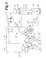
Referring toFIG. 2 , there is shown a schematic representation of thepower system 14 within thework machine 10 ofFIG. 1 . Thepower system 14 includes ahydraulic pump 22 that is configured to be powered by anelectric motor 21. Thepower system 14 includesmeans 54 for supplying hydraulic fluid, via thehydraulic pump 22, to thehydraulic cylinder 15. Thehydraulic cylinder 15 is configured to receive hydraulic fluid from thehydraulic pump 22. Thehydraulic pump 22 is fluidly connectable via asupply line 25 to afirst fluid volume 23 and asecond fluid volume 24 defined by thehydraulic cylinder 15. Thefirst fluid volume 23 and thesecond fluid volume 24 are also fluidly connectable to ahydraulic fluid tank 34 via atank line 46. Thesupply line 25 and thetank line 46 sharecommon portions first fluid volume 23 and thesecond fluid volume 24 are fluidly connectable to one another via thesupply line 25 and thecommon portions
Themoveable plunger 19 separates thefirst fluid volume 23 from thesecond fluid volume 24. Arod 45 couples theplunger 19 to a weight44 (loader bucket16) that is operable to drive the movement of theplunger 19 within thehydraulic cylinder 15. In order to lower theloader arms 13, theplunger 19 retracts under theweight 44, and in order to raise theloader arms 13, theplunger 19 advances against theweight 44. Those skilled in the art will recognize that the retraction rate can be hastened by supplying hydraulic fluid tosecond volume 24 by thehydraulic pump 22. Thefirst fluid volume 23 is positioned on an opposite side of theplunger 19 than theweight 44, and thesecond fluid volume 24 is positioned on a same side of theplunger 19 as theweight 44. Due to the space consumed by therod 45, as theplunger 19 retracts and advances, across-section 23aof thefirst fluid volume 23 will be greater than across-section 24aof thesecond fluid volume 24.
Thesupply line 25 includes first, second andthird valves tank line 46 includes afourth valve 29. Thevalves hydraulic cylinder 15. Thevalves electronic control module 20 via first, second, third and fourthvalve communication lines controls 17 are in communication with theelectronic control module 20 via the control communication lines18. Thus, the position of the implementcontrols 17 that corresponds to a desired position of theloader bucket 16 can be communicated to theelectronic control module 20 via the implementcommunication lines 18. Theelectronic control module 20 can then determine the position of eachvalve loader bucket 16. The controls may also be connected directly to the valves without departing from the present invention.
When theelectronic control module 20 determines that the implementcontrols 17 are in a neutral position, theelectronic control module 20 will ensure thatvalve 26 is in an open position, allowing any flow of hydraulic fluid from thehydraulic pump 22 to flow to afluid tank 34. When theelectronic control module 20, via the position of the implementcontrols 17, determines that the operator desires theloader bucket 16 to be raised, theelectronic control module 24 will ensure thatvalve 26 is in a closed position andvalve 28 is moved towards an open position. Thus, hydraulic fluid can flow from thehydraulic pump 22 viasupply line 25 to thefirst fluid volume 23 of thehydraulic cylinder 15. Theelectronic control module 20 will also ensure thatvalve 27 is in a closed position, andvalve 29 is in an open position, allowing hydraulic fluid from thesecond fluid volume 24 to flow to thefluid tank 34. Thus, theplunger 19 can advance against theweight 44, causing theloader bucket 16 to move upwards. When theelectronic control module 20 determines that the operator desires theloader bucket 16 to be lowered, theelectronic control module 20 can ensure thatvalve 26 andvalve 29 are in the closed position andvalves hydraulic pump 22 and thefirst fluid volume 23 to thesecond fluid volume 24 of thehydraulic cylinder 15. Further, the hydraulic fluid can also flow from thesecond fluid volume 24 to thefluid tank 34 acrossvalve 29. Thus, theplunger 19 can retract under theweight 44 and pump supplied hydraulic power, causing theloader bucket 16 to move downwards.
Thepower system 14 includesmeans 50 for converting hydraulic power produced within thehydraulic cylinder 15 to mechanical power. The means50 includes a fluid driven rotatingdevice 55, which preferably includes a variable displacementhydraulic motor 35. The variable displacementhydraulic motor 35 is configured to be powered by the hydraulic power produced within thehydraulic cylinder 15. Theelectronic control module 20 is also in communication with the variable displacementhydraulic motor 35 via amotor communication line 36. Although the fluid driven rotatingdevice 55 is preferably the variable displacementhydraulic motor 35, it should be appreciated that various fluid driven rotating devices, such as a turbine, could be used. The variable displacementhydraulic motor 35 is fluidly positioned between thefirst fluid volume 23 of thehydraulic cylinder 15 and thetank line 46. Thus, as theplunger 19 retracts, the portion of the pressurized fluid flowing from thefirst fluid volume 23 towards the second volume offluid 24 can be diverted and used to power the variable displacementhydraulic motor 35. When theelectronic control module 20 determines, via the position of the implementcontrols 17, that the operator desires theloader bucket 16 to be lowered, theelectronic control module 20 will vary the displacement of the variable displacementhydraulic motor 35 in order to achieve the desired retracting speed of theplunger 19, and thus, the desired lowering speed of theloader bucket 16 of theloader 12.
Thepower system 14 also includesmeans 51 for converting the mechanical power of the variable displacementhydraulic motor 35 to electrical power. The means51 includes agenerator 37 that is configured to be powered by the variable displacementhydraulic motor 35 and to supply electrical power to abattery 40 and/or acapacitor 39. The variable displacementhydraulic motor 35 is attached, in a conventional manner, to thegenerator 37. The rotation of the variable displacementhydraulic motor 35 powers thegenerator 37 that creates electrical power. Thegenerator 37 is in electrical communication with apower storage system 38 via storage communication lines41. Thepower system 14 includesmeans 52 for storing the electrical power in thebattery 40 andcapacitor 39. Although thepower storage system 38 could include either the capacitor or the battery, thepower storage system 38 preferably includes both thecapacitor 39 including a relatively large storage capacity and thebattery 40 including a relatively small storage capacity. Thebattery 40 and/orcapacitor 39 can be periodically connected, when needed, to an external power source in order to be re-charged. Thebattery 40 and thecapacitor 39 are configured to supply stored electrical power to theelectric motor 21. Thus, thepower system 14 includesmeans 53 for supplying theelectric motor 21 coupled to thehydraulic pump 22 with the electrical power from thebattery 40 and thecapacitor 39. Thebattery 40 is in electrical communication with theelectric motor 21 via anelectrical supply line 42. Preferably, themeans 53 includes aninverter 43 that is positioned within theelectrical supply line 42 in order to invert DC electric current from thebattery 40 to AC electric current for use within theelectric motor 21.
Referring toFIGS. 1 and 2 , the present invention will be described for the operation of thepower system 14 included withinwork machine 10. Although thepower system 14 drives the hydraulically activatedloader 12, it should be appreciated that the present invention contemplates power systems that drive various work machine implements and/or auxiliary systems. Further, the present invention contemplates applications in machines and/or vehicles other than work machines.
In order to operate thepower system 14, the hydraulic power created by the retractingplunger 19 is converted to mechanical power that drives thegenerator 37. When the operator moves the implementcontrols 17 to lower theloader bucket 16, the movement of thecontrols 17 will be communicated to theelectronic control module 20 via the control communication lines18. Theelectronic control module 20 will appropriately positionvalves bucket 16, which can be accomplished in a number of ways. For instance,valve 28 could be closed andvalve 27 opened such thatsecond volume 24 is filled viasupply line 25 frompump 22. Any excess fluid frompump 22 can be channeled back totank 34 acrossvalve 26. In a second alternative,valve 27 would be closed andvolume 24 filled fromtank 34 via a vacuum past the check valve located nearvalve 29. A third alternative could be some combination of the first and second alternatives. A fourth alternative could be to reducepump 22's output to zero, andopen valves volume 24 fromvolume 23. In any event, the first volume offluid 23 is pressurized by the weight of theloader bucket 16,loader arms 13, and any load that is inloader bucket 16. All or at least a portion of the fluid displaced fromfirst volume 23 can be channeled throughvariable displacement motor 35 on its way totank 34. By varying the displacement of the variable displacementhydraulic motor 35, theelectronic control module 20 will control the speed of the retraction of theplunger 19 in order to achieve the desired speed of the lowering of theloader bucket 16, The pressurized hydraulic fluid flowing through the variable displacement motor towards thetank line 46 totank 34 will drive the variable displacementhydraulic motor 35. The rotation of the variable displacementhydraulic motor 35 powers thegenerator 37 that creates electrical power. It is recognized that if total power regeneration is not required, fluid from thefirst fluid chamber 23 can be controllably diverted acrossvalve 28 to aid in filling thesecond fluid volume 24. Likewise, if too much fluid is being passed across thevalve 28 to thesecond fluid volume 24, thevalve 29 can be controllably opened to thetank 34 to avoid pressurizing thesecond fluid chamber 24.
In order to store the electrical power created by thegenerator 37, the electric current is delivered from thegenerator 37 to thecapacitor 39 via the storage communication lines41. Thecapacitor 39 is designed to have a larger storage capacity than thebattery 40. Thus, thecapacitor 39 can store the electric current which cannot be stored within thebattery 40. When the electric power stored within thebattery 40 falls below a predetermined amount, thecapacitor 39 can replenish the electric power within thebattery 40. Therefore, the hydraulic power created by the retractingplunger 19 can be stored as electric power within thebattery 40 andcapacitor 39 until the power is needed.
In order to power thehydraulic pump 22, the electric current stored within thebattery 40 is supplied to theelectric motor 21 via the electriccurrent supply lines 42. However, becauseelectric motor 21 generally operates on AC current and the current produced by thegenerator 37 is generally DC current, theinverter 43 will preferably invert the DC current from thebattery 40 to AC current to power theelectric motor 21. It should be appreciated that the present invention contemplates power systems in which an inverter is not necessary. The current supplied to theelectric motor 21 will drive themotor 21 to operate thehydraulic pump 22. Thehydraulic pump 22 can then supply hydraulic fluid via thesupply line 25 to thefirst fluid volume 23 during the advancement of theplunger 19 within thecylinder 15. Thehydraulic pump 22 can also supply hydraulic fluid to thesecond fluid volume 24 via thesupply line 25 when theplunger 19 is retracting. Duringplunger 19 retraction, the hydraulic fluid being produced by thehydraulic pump 22 will keep secondfluid volume 24 full and the remainder of the fluid is bypassed to thetank 34 acrossvalve 26. The excess portion of the pressurized hydraulic fluid flowing from thefirst fluid volume 23 to thefluid tank 34 during retraction drives the variable displacementhydraulic motor 35, and the energy recovery process can repeat itself. The energy recovered supplements the energy needed to be delivered from external sources to, and stored within, thebattery 40 and thecapacitor 39. Thus, the time period between charging thebattery 40 and/or thecapacitor 39 may be shortened, and the time between external chargings lengthened.
The present invention is advantageous because thepower system 14 including thebattery 40, thecapacitor 39 and the variable displacementhydraulic motor 35 is a relatively inexpensive and efficient alternative to the diesel engine. By removing the diesel engine from the power system, undesirable emissions, such as CO2and NOx, which are major factors in global warming and air pollution, are reduced, if not eliminated. Further, the noise and vibrations produced by thepower system 14 are also reduced. Moreover, by directing the flow of hydraulic fluid from thefirst fluid volume 23 duringplunger 19 retraction through the variable displacementhydraulic motor 35, thepower system 14 can be powered by an unthrottled hydraulic flow passing therethrough towards thetank line 46. Thus, by replacing a throttle valve that regulates the flow of fluid from thelarger cross-section 23aof thefirst fluid volume 23 duringplunger 19 retraction with thevariable displacement motor 35, the efficiency of thepower system 14 is increased.
In addition, because thepower system 14 includes thestorage power system 38, the hydraulic power can be stored as electrical power for prolonged use within thepower system 14. The stored electrical power can be used to drive theelectric motor 21, which in return can drive thehydraulic pump 22. Moreover, the present invention contemplates the stored energy being used to power additional electric apparatuses that are part of systems other than the hydraulic implement system. For instance, the electric motor could power a coolant pump that is part of a coolant system of the same work machine. Thus, there may be various uses for the energy stored by thepower system 14. Further, thebattery 40 andcapacitor 39 are relatively inexpensive compared to power storage systems including fuel cells, hydrogen absorbing alloy cells, and reformers.
It should be understood that the above description is intended for illustrative purposes only, and is not intended to limit the scope of the present invention in any way. Thus, those skilled in the art will appreciate that other aspects, objects, and advantages of the invention can be obtained from a study of the drawings, the disclosure and the appended claims.
Claims (19)
1. A power system comprising:
an electric motor being operable to power a hydraulic pump;
at least one hydraulic cylinder being fluidly connected to the hydraulic pump and defining a first fluid volume and a second fluid volume separated from one another via a moveable plunger;
a fluid driven rotating device being fluidly connected between the first fluid volume and the second fluid volume defined by the hydraulic cylinder and being operable to power a generator; and
a power storage system including at least one of a battery and a capacitor being in electrical communication with the generator and the electric motor.
2. The power system ofclaim 1 including an inverter being positioned between the electric motor and at least one of the capacitor and battery.
3. The power system ofclaim 1 wherein the fluid driven rotating device includes a variable displacement hydraulic motor.
4. The power system ofclaim 3 including an inverter being positioned between the electric motor and at least one of the capacitor and the battery.
5. A work machine comprising a work machine body; and
the power system ofclaim 1 being attached to the work machine body.
6. The work machine ofclaim 5 including an implement attached to the work machine body; and
the at least one hydraulic cylinder being operably coupled to move the implement.
7. The power system ofclaim 1 further comprising at least one adjustable valve disposed between the first volume and the second volume to selectively fluidly connect the same.
8. A power system, comprising:
means for supplying a pressurized hydraulic fluid to at least one hydraulic cylinder;
means for converting hydraulic power produced within said at least one hydraulic cylinder to mechanical power at least in part via a fluid driven rotating device;
said fluid driven rotating device being disposed at least partially within a fluid passage connecting said means for supplying with said at least one hydraulic cylinder;
means for converting the mechanical power to electrical power;
means for storing the electrical power in at least one of a battery and a capacitor;
means for supplying an electric motor coupled to the hydraulic pump with the electrical power from at least one of the battery and the capacitor; and
means for supplying hydraulic fluid, via the hydraulic pump, to the at least one hydraulic cylinder.
9. The power system ofclaim 8 wherein the means for converting hydraulic power to mechanical power includes a variable displacement hydraulic motor.
10. The power system ofclaim 8 wherein means for supplying the electrical power includes an inverter.
11. The power system ofclaim 8 wherein the at least one hydraulic cylinder being operably coupled to move a work machine implement.
12. A method of operating an electrical power system, comprising the steps of:
powering a generator, at least in part, by converting at least a portion of hydraulic power created within a hydraulic cylinder to mechanical power via a fluid driven rotating device fluidly positioned between a first volume and a second volume of the hydraulic cylinder;
storing electrical power created by the generator in at least one of a battery and a capacitor;
powering a hydraulic pump, at least in part, by supplying electrical power from at least one of the battery and capacitor to an electric motor coupled to the hydraulic pump; and
supplying hydraulic fluid to the hydraulic cylinder, at least in part, by operating the hydraulic pump.
13. The method ofclaim 12 wherein the step of powering the generator includes a step of attaching a variable displacement hydraulic motor to the generator.
14. The method ofclaim 12 wherein the step of powering the generator includes a step of producing hydraulic power by retracting a plunger within a hydraulic cylinder.
15. The method ofclaim 14 wherein the step of producing hydraulic power includes a step of controlling a speed of the retracting plunger, at least in part, by varying the displacement of the motor.
16. The method ofclaim 12 wherein the step of powering a hydraulic pump includes a step of inverting electrical current being supplied from at least one of the capacitor and the battery to the electric motor.
17. A power system comprising:
at least one of a battery and a capacitor being configured to supply stored electrical power to an electric motor;
a hydraulic pump being configured to be powered by the electric motor;
a hydraulic cylinder being configured to receive hydraulic fluid from the hydraulic pump said hydraulic cylinder defining first and second fluid volumes;
a fluid driven rotating device being configured to be powered by hydraulic power produced within the hydraulic cylinder;
said fluid driven rotating device being positioned within a fluid pathway connecting said first and second volumes, wherein said fluid pathway includes at least two adjustable valves disposed in parallel; and
a generator being configured to be powered by the fluid driven rotating device and to supply electrical power to at least one of the battery and the capacitor.
18. The power system ofclaim 17 including an inverter configured to invert the electrical power being supplied from the at least one battery and capacitor to the electric motor.
19. The power system ofclaim 17 wherein the fluid driven rotating device includes a variable displacement hydraulic motor.
Priority Applications (5)
| Application Number | Priority Date | Filing Date | Title |
|---|---|---|---|
| US10/713,667US6945039B2 (en) | 2003-11-14 | 2003-11-14 | Power system and work machine using same |
| PCT/US2004/032750WO2005052384A1 (en) | 2003-11-14 | 2004-10-04 | Power system and work machine using same |
| DE112004002201TDE112004002201T5 (en) | 2003-11-14 | 2004-10-04 | Drive system and working machine using this |
| CN200480030769.2ACN100538086C (en) | 2003-11-14 | 2004-10-04 | The work mechanism of power system and this power system of use |
| JP2006539490AJP2007516392A (en) | 2003-11-14 | 2004-10-04 | Power system and work machine using the same |
Applications Claiming Priority (1)
| Application Number | Priority Date | Filing Date | Title |
|---|---|---|---|
| US10/713,667US6945039B2 (en) | 2003-11-14 | 2003-11-14 | Power system and work machine using same |
Publications (2)
| Publication Number | Publication Date |
|---|---|
| US20050103007A1 US20050103007A1 (en) | 2005-05-19 |
| US6945039B2true US6945039B2 (en) | 2005-09-20 |
Family
ID=34573774
Family Applications (1)
| Application Number | Title | Priority Date | Filing Date |
|---|---|---|---|
| US10/713,667Expired - Fee RelatedUS6945039B2 (en) | 2003-11-14 | 2003-11-14 | Power system and work machine using same |
Country Status (5)
| Country | Link |
|---|---|
| US (1) | US6945039B2 (en) |
| JP (1) | JP2007516392A (en) |
| CN (1) | CN100538086C (en) |
| DE (1) | DE112004002201T5 (en) |
| WO (1) | WO2005052384A1 (en) |
Cited By (20)
| Publication number | Priority date | Publication date | Assignee | Title |
|---|---|---|---|---|
| US20050103006A1 (en)* | 2003-11-14 | 2005-05-19 | Kazunori Yoshino | Power system and work machine using same |
| US20070034523A1 (en)* | 2005-08-10 | 2007-02-15 | Yerazunis William S | Fuel-cell actuated mechanical device |
| US20090007747A1 (en)* | 2007-04-27 | 2009-01-08 | Wilson Tool International Inc. | Live tooling systems for machine tools |
| US20090068547A1 (en)* | 2004-12-20 | 2009-03-12 | Joseph Mario Ambrosio | Thermally managed battery enclosure for electric and hybrid electric vehicles |
| US20090236156A1 (en)* | 2008-03-20 | 2009-09-24 | Terex-Telelect, Inc. | Hybrid drive for hydraulic power |
| US20090277168A1 (en)* | 2008-05-08 | 2009-11-12 | Caterpillar Inc. | Hybrid system for a powertrain and hydraulic system |
| US20100219007A1 (en)* | 2007-07-12 | 2010-09-02 | Odyne Systems, Llc | Hybrid vehicle drive system and method and idle reduction system and method |
| US20140046552A1 (en)* | 2011-05-25 | 2014-02-13 | Hitachi Construction Machinery Co., Ltd. | Electric drive unit for construction machine |
| US8818588B2 (en) | 2007-07-12 | 2014-08-26 | Odyne Systems, Llc | Parallel hybrid drive system utilizing power take off connection as transfer for a secondary energy source |
| US8978798B2 (en) | 2007-10-12 | 2015-03-17 | Odyne Systems, Llc | Hybrid vehicle drive system and method and idle reduction system and method |
| US9061680B2 (en) | 2007-07-12 | 2015-06-23 | Odyne Systems, Llc | Hybrid vehicle drive system and method for fuel reduction during idle |
| US9283954B2 (en) | 2007-07-12 | 2016-03-15 | Odyne Systems, Llc | System for and method of fuel optimization in a hybrid vehicle |
| US9484602B1 (en) | 2013-08-22 | 2016-11-01 | OSC Manufacturing & Equipment Services, Inc. | Light tower having a battery housing |
| US9878616B2 (en) | 2007-07-12 | 2018-01-30 | Power Technology Holdings Llc | Hybrid vehicle drive system and method using split shaft power take off |
| US9979338B2 (en) | 2015-06-30 | 2018-05-22 | Cnh Industrial America Llc | Alternator control system for a planter |
| US10427520B2 (en) | 2013-11-18 | 2019-10-01 | Power Technology Holdings Llc | Hybrid vehicle drive system and method using split shaft power take off |
| US10749224B2 (en) | 2015-08-17 | 2020-08-18 | OSC Manufacturing & Equipment Services, Inc. | Rechargeable battery power system having a battery with multiple uses |
| US11225240B2 (en) | 2011-12-02 | 2022-01-18 | Power Technology Holdings, Llc | Hybrid vehicle drive system and method for fuel reduction during idle |
| US11584242B2 (en) | 2007-07-12 | 2023-02-21 | Power Technology Holdings Llc | Hybrid vehicle drive system and method and idle reduction system and method |
| US12330657B2 (en) | 2011-12-02 | 2025-06-17 | Power Technology Holdings Llc | Hybrid vehicle drive system and method for fuel reduction during idle |
Families Citing this family (7)
| Publication number | Priority date | Publication date | Assignee | Title |
|---|---|---|---|---|
| JP5090720B2 (en)* | 2005-12-12 | 2012-12-05 | キャタピラー インコーポレイテッド | Energy regeneration system for work machines |
| JP2007284873A (en)* | 2006-04-12 | 2007-11-01 | Takeuchi Seisakusho:Kk | Work vehicle |
| WO2009125833A1 (en)* | 2008-04-11 | 2009-10-15 | 住友重機械工業株式会社 | Operating machine |
| US20130140822A1 (en)* | 2011-12-05 | 2013-06-06 | Fabio Saposnik | Fluid power driven charger |
| CN104709834B (en)* | 2013-12-11 | 2017-08-04 | 北汽福田汽车股份有限公司 | Turn round speed-adjusting and control system and crane |
| CN103629196B (en)* | 2013-12-18 | 2015-09-30 | 哈尔滨工程大学 | A kind of vehicle energy-saving device based on engineering machinery hydraulic drive system |
| DE102021001733A1 (en)* | 2021-04-03 | 2022-10-06 | Hydac Fluidtechnik Gmbh | contraption |
Citations (15)
| Publication number | Priority date | Publication date | Assignee | Title |
|---|---|---|---|---|
| US3512072A (en)* | 1967-11-13 | 1970-05-12 | Allis Chalmers Mfg Co | Elevated load potential energy recovery in an electric truck |
| US3641416A (en)* | 1969-10-08 | 1972-02-08 | Motorola Inc | Hydrodynamic charging system |
| US3947744A (en)* | 1974-10-21 | 1976-03-30 | Allis-Chalmers Corporation | Electric truck having elevated load potential energy recovery with means to adjust rate of carriage descent |
| US3956891A (en)* | 1974-12-30 | 1976-05-18 | Allis-Chalmers Corporation | Closed center hydraulic system for lift trucks |
| DE2618046A1 (en) | 1976-04-24 | 1977-11-10 | Sven O I Jonsson | Stored energy utilisation system - has hydraulic motor driven by lowering pressure coupled to dynamo recharging battery |
| DE2724383A1 (en) | 1977-05-28 | 1978-11-30 | Jungheinrich Kg | Forklift truck hydraulic lift operating system - uses fluid released on lowering to drive generator for power recovery |
| US4702076A (en)* | 1984-01-13 | 1987-10-27 | Dynamic Hydraulic Systems, Inc. | Hydraulically operated clam-shell device |
| US4761954A (en)* | 1987-03-16 | 1988-08-09 | Dynamic Hydraulic Systems, Inc. | Fork-lift system |
| US4961316A (en)* | 1987-10-28 | 1990-10-09 | Bt Industries Aktiebolag | Controlled electric pump drive for hydraulic lifting arrangement with gas spring in motor |
| DE4324464A1 (en) | 1993-07-21 | 1995-01-26 | Jungheinrich Ag | Hydraulic lifting apparatus for battery-operated industrial trucks |
| US6005360A (en)* | 1995-11-02 | 1999-12-21 | Sme Elettronica Spa | Power unit for the supply of hydraulic actuators |
| JP2002195218A (en) | 2000-12-26 | 2002-07-10 | Shin Caterpillar Mitsubishi Ltd | Energy regenerative apparatus for construction equipment |
| US6460332B1 (en) | 1998-11-04 | 2002-10-08 | Komatsu Ltd. | Pressure oil energy recover/regenation apparatus |
| DE10128584A1 (en) | 2001-06-13 | 2002-12-19 | Linde Ag | Hydraulic unit for battery-operated fork lift truck or similar has motor for recovering energy during lowering movement and pump for supplying lift device and each with variable displacement volume adjustable by electric adjusting device |
| US6725581B2 (en)* | 2002-06-04 | 2004-04-27 | Komatsu Ltd. | Construction equipment |
Family Cites Families (5)
| Publication number | Priority date | Publication date | Assignee | Title |
|---|---|---|---|---|
| JPS4956348A (en)* | 1972-09-29 | 1974-05-31 | ||
| JPH11107311A (en)* | 1997-09-30 | 1999-04-20 | Yutani Heavy Ind Ltd | Power generator of construction machine |
| JP2002147413A (en)* | 2000-11-08 | 2002-05-22 | Yasuo Tokioka | Hydraulic power device |
| JP2003049809A (en)* | 2001-08-07 | 2003-02-21 | Hitachi Constr Mach Co Ltd | Pressure oil energy recovering device and construction machine with the same |
| JP2003252588A (en)* | 2002-03-05 | 2003-09-10 | Mitsubishi Heavy Ind Ltd | Energy recovery type cargo handling machine |
- 2003
- 2003-11-14USUS10/713,667patent/US6945039B2/ennot_activeExpired - Fee Related
- 2004
- 2004-10-04WOPCT/US2004/032750patent/WO2005052384A1/enactiveApplication Filing
- 2004-10-04DEDE112004002201Tpatent/DE112004002201T5/ennot_activeCeased
- 2004-10-04JPJP2006539490Apatent/JP2007516392A/enactivePending
- 2004-10-04CNCN200480030769.2Apatent/CN100538086C/ennot_activeExpired - Fee Related
Patent Citations (15)
| Publication number | Priority date | Publication date | Assignee | Title |
|---|---|---|---|---|
| US3512072A (en)* | 1967-11-13 | 1970-05-12 | Allis Chalmers Mfg Co | Elevated load potential energy recovery in an electric truck |
| US3641416A (en)* | 1969-10-08 | 1972-02-08 | Motorola Inc | Hydrodynamic charging system |
| US3947744A (en)* | 1974-10-21 | 1976-03-30 | Allis-Chalmers Corporation | Electric truck having elevated load potential energy recovery with means to adjust rate of carriage descent |
| US3956891A (en)* | 1974-12-30 | 1976-05-18 | Allis-Chalmers Corporation | Closed center hydraulic system for lift trucks |
| DE2618046A1 (en) | 1976-04-24 | 1977-11-10 | Sven O I Jonsson | Stored energy utilisation system - has hydraulic motor driven by lowering pressure coupled to dynamo recharging battery |
| DE2724383A1 (en) | 1977-05-28 | 1978-11-30 | Jungheinrich Kg | Forklift truck hydraulic lift operating system - uses fluid released on lowering to drive generator for power recovery |
| US4702076A (en)* | 1984-01-13 | 1987-10-27 | Dynamic Hydraulic Systems, Inc. | Hydraulically operated clam-shell device |
| US4761954A (en)* | 1987-03-16 | 1988-08-09 | Dynamic Hydraulic Systems, Inc. | Fork-lift system |
| US4961316A (en)* | 1987-10-28 | 1990-10-09 | Bt Industries Aktiebolag | Controlled electric pump drive for hydraulic lifting arrangement with gas spring in motor |
| DE4324464A1 (en) | 1993-07-21 | 1995-01-26 | Jungheinrich Ag | Hydraulic lifting apparatus for battery-operated industrial trucks |
| US6005360A (en)* | 1995-11-02 | 1999-12-21 | Sme Elettronica Spa | Power unit for the supply of hydraulic actuators |
| US6460332B1 (en) | 1998-11-04 | 2002-10-08 | Komatsu Ltd. | Pressure oil energy recover/regenation apparatus |
| JP2002195218A (en) | 2000-12-26 | 2002-07-10 | Shin Caterpillar Mitsubishi Ltd | Energy regenerative apparatus for construction equipment |
| DE10128584A1 (en) | 2001-06-13 | 2002-12-19 | Linde Ag | Hydraulic unit for battery-operated fork lift truck or similar has motor for recovering energy during lowering movement and pump for supplying lift device and each with variable displacement volume adjustable by electric adjusting device |
| US6725581B2 (en)* | 2002-06-04 | 2004-04-27 | Komatsu Ltd. | Construction equipment |
Cited By (37)
| Publication number | Priority date | Publication date | Assignee | Title |
|---|---|---|---|---|
| US7197871B2 (en)* | 2003-11-14 | 2007-04-03 | Caterpillar Inc | Power system and work machine using same |
| US20050103006A1 (en)* | 2003-11-14 | 2005-05-19 | Kazunori Yoshino | Power system and work machine using same |
| US20090068547A1 (en)* | 2004-12-20 | 2009-03-12 | Joseph Mario Ambrosio | Thermally managed battery enclosure for electric and hybrid electric vehicles |
| US8115450B2 (en) | 2004-12-20 | 2012-02-14 | Odyne Systems, Llc | Thermally managed battery enclosure for electric and hybrid electric vehicles |
| US20070034523A1 (en)* | 2005-08-10 | 2007-02-15 | Yerazunis William S | Fuel-cell actuated mechanical device |
| US7409830B2 (en)* | 2005-08-10 | 2008-08-12 | Mitsubishi Electric Research Laboratories, Inc. | Fuel-cell actuated mechanical device |
| US7823434B2 (en) | 2007-04-27 | 2010-11-02 | Wilson Tool International Inc. | Live tooling systems for machine tools |
| US20090007747A1 (en)* | 2007-04-27 | 2009-01-08 | Wilson Tool International Inc. | Live tooling systems for machine tools |
| US9061680B2 (en) | 2007-07-12 | 2015-06-23 | Odyne Systems, Llc | Hybrid vehicle drive system and method for fuel reduction during idle |
| US9751518B2 (en) | 2007-07-12 | 2017-09-05 | Power Technology Holdings, Llc | Hybrid vehicle drive system and method and idle reduction system and method |
| US11801824B2 (en) | 2007-07-12 | 2023-10-31 | Power Technology Holdings, Llc | Hybrid vehicle drive system and method and idle reduction system and method |
| US11584242B2 (en) | 2007-07-12 | 2023-02-21 | Power Technology Holdings Llc | Hybrid vehicle drive system and method and idle reduction system and method |
| US11077842B2 (en) | 2007-07-12 | 2021-08-03 | Power Technology Holdings Llc | Hybrid vehicle drive system and method and idle reduction system and method |
| US8408341B2 (en) | 2007-07-12 | 2013-04-02 | Odyne Systems, Llc | Hybrid vehicle drive system and method and idle reduction system and method |
| US10792993B2 (en) | 2007-07-12 | 2020-10-06 | Power Technology Holdings Llc | Vehicle drive system and method and idle reduction system and method |
| US8818588B2 (en) | 2007-07-12 | 2014-08-26 | Odyne Systems, Llc | Parallel hybrid drive system utilizing power take off connection as transfer for a secondary energy source |
| US8905166B2 (en) | 2007-07-12 | 2014-12-09 | Odyne Systems, Llc | Hybrid vehicle drive system and method and idle reduction system and method |
| US10214199B2 (en) | 2007-07-12 | 2019-02-26 | Power Technology Holdings Llc | Hybrid vehicle drive system and method and idle reduction system and method |
| US10071647B2 (en) | 2007-07-12 | 2018-09-11 | Power Technology Holdings Llc | System for and method of fuel optimization in a hybrid vehicle |
| US9283954B2 (en) | 2007-07-12 | 2016-03-15 | Odyne Systems, Llc | System for and method of fuel optimization in a hybrid vehicle |
| US9878616B2 (en) | 2007-07-12 | 2018-01-30 | Power Technology Holdings Llc | Hybrid vehicle drive system and method using split shaft power take off |
| US20100219007A1 (en)* | 2007-07-12 | 2010-09-02 | Odyne Systems, Llc | Hybrid vehicle drive system and method and idle reduction system and method |
| US9643593B2 (en) | 2007-07-12 | 2017-05-09 | Power Technology Holdings Llc | Hybrid vehicle drive system and method for fuel reduction during idle |
| US8978798B2 (en) | 2007-10-12 | 2015-03-17 | Odyne Systems, Llc | Hybrid vehicle drive system and method and idle reduction system and method |
| US20090236156A1 (en)* | 2008-03-20 | 2009-09-24 | Terex-Telelect, Inc. | Hybrid drive for hydraulic power |
| US7900724B2 (en)* | 2008-03-20 | 2011-03-08 | Terex-Telelect, Inc. | Hybrid drive for hydraulic power |
| US20090277168A1 (en)* | 2008-05-08 | 2009-11-12 | Caterpillar Inc. | Hybrid system for a powertrain and hydraulic system |
| US7980073B2 (en) | 2008-05-08 | 2011-07-19 | Caterpillar Inc. | Hybrid system for a powertrain and hydraulic system |
| US20140046552A1 (en)* | 2011-05-25 | 2014-02-13 | Hitachi Construction Machinery Co., Ltd. | Electric drive unit for construction machine |
| US9347203B2 (en)* | 2011-05-25 | 2016-05-24 | Hitachi Construction Machinery Co., Ltd. | Electric drive unit for construction machine |
| US11225240B2 (en) | 2011-12-02 | 2022-01-18 | Power Technology Holdings, Llc | Hybrid vehicle drive system and method for fuel reduction during idle |
| US12330657B2 (en) | 2011-12-02 | 2025-06-17 | Power Technology Holdings Llc | Hybrid vehicle drive system and method for fuel reduction during idle |
| US10442481B2 (en) | 2013-08-22 | 2019-10-15 | Osc, Manufacturing & Equipment Services, Inc. | Method of rebuilding a used piece of equipment comprising replacing an interal combustion engine with a rechargeable battery power system |
| US9484602B1 (en) | 2013-08-22 | 2016-11-01 | OSC Manufacturing & Equipment Services, Inc. | Light tower having a battery housing |
| US10427520B2 (en) | 2013-11-18 | 2019-10-01 | Power Technology Holdings Llc | Hybrid vehicle drive system and method using split shaft power take off |
| US9979338B2 (en) | 2015-06-30 | 2018-05-22 | Cnh Industrial America Llc | Alternator control system for a planter |
| US10749224B2 (en) | 2015-08-17 | 2020-08-18 | OSC Manufacturing & Equipment Services, Inc. | Rechargeable battery power system having a battery with multiple uses |
Also Published As
| Publication number | Publication date |
|---|---|
| JP2007516392A (en) | 2007-06-21 |
| US20050103007A1 (en) | 2005-05-19 |
| WO2005052384A1 (en) | 2005-06-09 |
| CN1871441A (en) | 2006-11-29 |
| DE112004002201T5 (en) | 2006-10-05 |
| CN100538086C (en) | 2009-09-09 |
Similar Documents
| Publication | Publication Date | Title |
|---|---|---|
| US6945039B2 (en) | Power system and work machine using same | |
| US7197871B2 (en) | Power system and work machine using same | |
| JP4480908B2 (en) | Hybrid excavator | |
| JP3647319B2 (en) | Hydraulic drive | |
| US20100107620A1 (en) | Rotary flow control valve with energy recovery | |
| CN102877495B (en) | Hybrid power system for recovering potential energy of movable arm of excavating machine | |
| CN104912138B (en) | Hybrid power excavator movable arm potential energy recovery system and work method thereof | |
| JP2000136806A (en) | Pressure oil energy recovery device and pressure oil energy recovery / regeneration device | |
| JP2011069432A (en) | Regenerative control device of working machine | |
| US20060090462A1 (en) | Energy regeneration system for working machinery | |
| CN103154390A (en) | Energy management system for heavy equipment | |
| JP2009127643A (en) | Boom drive circuit for construction machinery | |
| CA2813392C (en) | Energy management and storage system | |
| KR20210075258A (en) | Electric excavator using energy storage apparatus | |
| KR101155785B1 (en) | Hybrid system of an excavator | |
| Padovani et al. | Downsizing the electric machines of energy-efficient electro-hydraulic drives for mobile hydraulics | |
| JP3534699B2 (en) | Energy regeneration equipment for construction machinery | |
| CN118128794A (en) | Boom telescopic hydraulic system and aerial work platform | |
| CN118647791A (en) | Gas supply system | |
| KR101936206B1 (en) | Excavator system for hydraulic hybrid having regenerated energy using motor-generator | |
| KR101936260B1 (en) | Excavator system for hydraulic hybrid having regenerated energy using hydraulic transfomer | |
| US20050235638A1 (en) | Hydraulic system | |
| US20250264116A1 (en) | Energy Recovery Charging of an Accumulator in a Low-Pressure Compensation Circuit of an Electro-Hydrostatic Actuator | |
| KR102873487B1 (en) | Power distribution system for excavators | |
| JP2007162457A (en) | Energy regeneration system for working machinery |
Legal Events
| Date | Code | Title | Description |
|---|---|---|---|
| AS | Assignment | Owner name:CATERPILLAR INC., ILLINOIS Free format text:ASSIGNMENT OF ASSIGNORS INTEREST;ASSIGNOR:YOSHINO, KAZUNORI;REEL/FRAME:014707/0054 Effective date:20031030 Owner name:SHIN CATERPILLAR MITSUBISHI LTD., JAPAN Free format text:ASSIGNMENT OF ASSIGNORS INTEREST;ASSIGNOR:YOSHINO, KAZUNORI;REEL/FRAME:014707/0054 Effective date:20031030 | |
| FPAY | Fee payment | Year of fee payment:4 | |
| AS | Assignment | Owner name:CATERPILLAR S.A.R.L.,SWITZERLAND Free format text:ASSIGNMENT OF ASSIGNORS INTEREST;ASSIGNOR:CATERPILLAR JAPAN LTD.;REEL/FRAME:024233/0895 Effective date:20091231 | |
| FPAY | Fee payment | Year of fee payment:8 | |
| REMI | Maintenance fee reminder mailed | ||
| LAPS | Lapse for failure to pay maintenance fees | Free format text:PATENT EXPIRED FOR FAILURE TO PAY MAINTENANCE FEES (ORIGINAL EVENT CODE: EXP.) | |
| STCH | Information on status: patent discontinuation | Free format text:PATENT EXPIRED DUE TO NONPAYMENT OF MAINTENANCE FEES UNDER 37 CFR 1.362 | |
| FP | Lapsed due to failure to pay maintenance fee | Effective date:20170920 |