US6943843B2 - Camera positioning system and method for eye-to eye communication - Google Patents
Camera positioning system and method for eye-to eye communicationDownload PDFInfo
- Publication number
- US6943843B2 US6943843B2US09/966,334US96633401AUS6943843B2US 6943843 B2US6943843 B2US 6943843B2US 96633401 AUS96633401 AUS 96633401AUS 6943843 B2US6943843 B2US 6943843B2
- Authority
- US
- United States
- Prior art keywords
- camera
- display
- magnet
- housing
- person
- Prior art date
- Legal status (The legal status is an assumption and is not a legal conclusion. Google has not performed a legal analysis and makes no representation as to the accuracy of the status listed.)
- Expired - Lifetime, expires
Links
Images


Classifications
- H—ELECTRICITY
- H04—ELECTRIC COMMUNICATION TECHNIQUE
- H04N—PICTORIAL COMMUNICATION, e.g. TELEVISION
- H04N7/00—Television systems
- H04N7/14—Systems for two-way working
- H04N7/141—Systems for two-way working between two video terminals, e.g. videophone
- H04N7/142—Constructional details of the terminal equipment, e.g. arrangements of the camera and the display
- H04N7/144—Constructional details of the terminal equipment, e.g. arrangements of the camera and the display camera and display on the same optical axis, e.g. optically multiplexing the camera and display for eye to eye contact
Definitions
- the present inventionrelates generally to the field of video communication. More specifically, the present invention relates to a system and method for positioning a camera to enable eye-to-eye videoconferencing.
- Videoconferencingis rapidly becoming a popular method of communication between remote parties who wish to approximate face-to-face contact without travel. As bandwidth limitations are ameliorated, more events such as business meetings, family discussions, and shopping may be expected to take place through videoconferencing.
- Some deviceshave been made in an attempt to more closely simulate eye-to-eye communication. Such devices may involve, for example, the use of complex and specialized display screens with advanced optical and projection equipment. Unfortunately, most consumers would wish to communicate via conventional, inexpensive personal computer or entertainment hardware such as “webcams” and televisions.
- a system and method for obtaining an image of a person from along the person's eye level when the person is looking at the image of a second person on a screenPreferably, such a system should lend the impression of eye-to-eye communication without unduly burdening other aspects of the videoconferencing process. Additionally, such a system and method should preferably be adaptable to existing consumer hardware.
- FIG. 1is a perspective view of one embodiment of an apparatus for obtaining a video signal from a position proximate an eye level of a person viewing a display screen;
- FIG. 2is a block diagram of the functional components of the wireless camera of FIG. 1 ;
- FIG. 3is an exploded, perspective view of the attachment mechanism and housing of FIG. 1 ;
- FIG. 4is a side-elevation, cross-sectional view of a portion of the attachment mechanism and housing of FIG. 1 ;
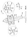
- FIG. 5is a rearward-oriented, perspective view of an alternative embodiment of an apparatus for obtaining a video signal from a position proximate an eye level of a person viewing a display screen;
- FIG. 6is a side-elevation view of another alternative embodiment of an apparatus for obtaining a video signal from a position proximate an eye level of a person viewing a display screen.
- the present inventionsolves the foregoing problems and disadvantages by providing an apparatus for obtaining a video signal from a position proximate an eye level of a person viewing a display screen, and a related method of positioning the camera.
- the apparatus and methodmay be configured in a wide variety of ways to suit specific videoconferencing situations.
- the apparatusmay include a camera having a lens contained within a housing.
- the cameramay take the form of a wireless camera in which electromagnetic waves carry audio and video signals to an audio/video receiver unit.
- some form of wiremay facilitate communication between the camera and the audio/video receiver unit.
- the wireless camerais secured to an attachment mechanism.
- the attachment mechanismis a suction fitting, such as a suction cup.
- the suction cupincludes a concave face, a convex face, and an engagement member that is inserted into and releasably or permanently retained within an orifice in the housing to secure the suction cup to the housing.
- the suction cupWhen pressed against a screen portion of a display screen, the suction cup will push out the air between the concave face and the screen portion, creating a vacuum.
- This vacuumremovably secures the suction cup, and therefore the camera, to the screen portion such that the camera is disposed between the display screen and the person using the apparatus.
- Videoconferencingmay occur between a person using the apparatus and another person whose image is displayed on the screen portion of the display screen.
- the person using the apparatusmay position the suction cup and wireless camera proximate the eyes of the image on the screen portion. This provides the realistic semblance of eye-to-eye communication for the person whose image is displayed on the screen portion, i.e., the person with whom the person using the apparatus is communicating.
- the actual location of the camerawill vary depending on the location of the image on the screen portion. For some people, moving the camera to an eye level position will require the wireless camera to be positioned at the center of the screen portion. For other viewers, however, the wireless camera may need to be positioned in other areas of the screen portion.
- the apparatusmay include a camera holder secured to the display screen.
- the camera holdermay include an open-ended pocket having a scalloped portion that permits access to the wireless camera for insertion and removal and/or operation of the camera from within the camera holder.
- the camera holdermay be secured to the display screen in an orientation such that the wireless camera may be inserted into the camera holder and rest at the bottom of the open-ended pocket.
- the wireless camera and suction cupmay be removed from the screen portion and inserted into the open-ended pocket.
- the screen portionmay be substantially free of residue from the suction cup.
- the wireless cameramay have an adjustable pan and/or tilt setting, so that during videoconferencing the person need not have his or her head directly aligned with the display screen in the lateral or transverse directions.
- the personmay also use such a pan and/or tilt setting to utilize the wireless camera for videoconferencing when the wireless camera is located in the camera holder.
- the wireless cameramay include first and second antennas, a receiver, a driver circuit, an image sensor, a correlated double sampling (CDS) unit, a gain control unit, a transmitter, and a power source.
- the wireless cameramay also include various other or different components as will be known to those skilled in the art.
- the wireless cameramay be in communication with an audio/video receiver unit that is configured to transmit signals recorded by the wireless camera over a communications network, and to receive a series of video signals for display on the screen portion.
- the attachment mechanismincludes an adhesive layer, and in particular, takes the form of first and second strips of double-sided tape secured to the housing.
- Each strip of double-sided tapeincludes a backing layer with a first adhesive layer on one side and a second adhesive layer on the opposite side.
- the first adhesive layersecures the double-sided tape to the housing.
- the second adhesive layerremovably secures the double-sided tape to the screen portion such that the camera is disposed between the display screen and the person.
- the adhesive layersmay be of any type that can be firmly adhered to a nonporous surface, such as a glass or plastic screen, and removed without damaging the surface.
- the display screentakes the form of a flat panel display.
- the attachment mechanismincludes first and second magnets.
- the housing of the wireless camerais secured to one side of the first magnet. If the first and second magnets are substantially aligned on opposite sides of the screen portion, the magnetic force between the first and second magnets removably secures the first magnet to the screen portion such that the wireless camera is disposed between the flat panel display and the person.
- Protective padsmay be secured to the first and second magnets to protect the display screen from scratches, gouges, or the like.
- a perspective viewshows one embodiment of an apparatus 100 for obtaining a video signal from a position proximate an eye level of a person viewing a display screen.
- the apparatus 100may have a longitudinal direction 102 , a lateral direction 104 , and a transverse direction 106 .
- a display screen 108may be of any known type such as a cathode ray tube (CRT) screen, a liquid crystal display (LCD), liquid plasma display, analog or digital projection, or the like.
- the display screen 108may be a device commonly available to consumers, such as a computer monitor or television.
- the display screen 108may have a housing 110 that contains the internal components of the display screen, and a screen portion 112 on which images are displayed.
- the display screen 108may be used by a person 118 to conduct videoconferencing with a second person, whose image 120 is shown on the screen portion 112 of the display screen 108 .
- the person 118may be expected to look at the image 120 , so that the person 118 is looking along an eye level 122 , as shown by a dashed line in FIG. 1 .
- the person 118may, for example, look approximately at the eyes of the person whose image 120 is shown on the screen portion 112 .
- the display screen 108may have a left side 124 , a right side 126 , a top side 128 , a bottom side 130 , and a front side 132 . Furthermore, the display screen 108 may have a base 134 that supports the weight of the display screen 108 .
- the base 134may be rigid, or may permit swiveling or tilting of the display screen 108 . Of course, the display screen 108 may also operate without a base 134 .
- the apparatus 100has a camera 136 having a lens 138 contained within a housing 140 .
- the lens 138may, for example, be retained within an aperture of the housing 140 so that light is able to enter the housing 140 through the lens 138 .
- the camera 136takes the form of a wireless camera 136 .
- the wireless camera 136transmits audio and video signals of the person 118 to an audio/video receiver unit (not shown). The operation of the wireless camera 136 will be described in greater detail in connection with FIG. 2 .
- Wirelessshould not be construed to mean that the wireless camera 136 does not have any wires connected to it. Rather, the term “wireless” should be construed in accordance with its typical meaning within the field of electronics, i.e., as referring to a method of information transfer in which electromagnetic waves carry the signal over part or all of the communication path. Moreover, the present invention is not limited to use with a wireless camera 136 . Some form of wire, such as shielded or unshielded twisted pair, coaxial cable, or optical fiber, may facilitate communication between the camera 136 and the audio/video receiver unit.
- the wireless camera 136is secured to an attachment mechanism 142 , which may take the form of a suction fitting 142 .
- a “suction fitting”is any device that holds two objects together by creating a region of low pressure fluid between the objects.
- flexible enclosuressuch as suction cups, as well as rigid, evacuated volumes are all suction fittings.
- the suction fitting 142is a suction cup 142 having a convex face 144 , a concave face 146 , and an engagement member (not shown) on the convex face 144 .
- the suction cup 142may be made of an elastomer such as latex or some other suitable material. When pressed against the screen portion 112 , the suction cup 142 will push out the air between the concave face 146 and the screen portion 112 , creating a vacuum. This vacuum causes the suction cup 142 to be removably secured to the screen portion 112 .
- the word “secure” by itselfhas a broader meaning than the phrase “removably secure.”
- to “removably secure” two objectsmeans to attach them in such a way that they may thereafter be separated by hand in a nondestructive manner.
- the suction cup 142may thereafter be removed from the screen portion 112 by pulling the suction cup 142 away from the screen portion 112 .
- to simply “secure” two objectsmeans to attach them in any fashion, either removably or permanently.
- a suction fitting 142 in accordance with the present inventionmay be any device that removably secures the camera to the screen portion 112 through the use of suction.
- the suction fitting 142may take the form of a container that is capable of forming an enclosed area when pressed against the screen portion 112 .
- a suction pumpmay be secured to the container to pump the air out of the enclosed area, thereby creating a vacuum within the enclosed area and causing the container to be removably secured to the screen portion 112 .
- the person 118may position the suction cup 142 , and therefore the wireless camera 136 , proximate the eyes of the image 120 on the screen portion 112 , as shown in FIG. 1 .
- Thisprovides the realistic semblance of eye-to-eye communication for the person whose image 120 is displayed on the screen portion 112 , i.e., the person with whom the person 118 using the apparatus 100 is communicating.
- the wireless camera 136is not disposed precisely along the eye level 122 . If the wireless camera 136 is simply positioned proximate, or close to, the eye level 122 as shown in FIG. 1 , the person whose image 120 is shown on the screen portion 112 may not notice that the person 118 is looking slightly to one side, or up or down. Thus, if both parties involved in videoconferencing are using an apparatus 100 , slight displacement of the wireless cameras 136 from eye level 122 may provide realistic eye-to-eye communication for both parties simultaneously. However, in accordance with the present invention, the wireless camera 136 may be positioned precisely along eye level 122 so that a portion of the image 120 may be blocked by the wireless camera 136 .
- the actual location of the wireless camera 136will vary depending on the position of the image 120 on the screen portion 112 . In some situations, moving the wireless camera 136 to a position proximate the eye level 122 will require the wireless camera 136 to be positioned at the center of the screen portion 112 . In other situations, however, the wireless camera 136 may need to be positioned in other areas of the screen portion 112 .
- the apparatus 100includes a camera holder 150 secured to the front side 132 of the display screen 108 , to the side of the screen portion 112 and approximately halfway between the top side 128 and bottom side 130 of the display screen 108 .
- the camera holder 150includes an open-ended pocket 152 , which consists of a front portion 154 , first and second side portions 156 and 158 , a back portion 160 , and a bottom portion 161 .
- the front portion 154is joined to the side portions 156 and 158 by first and second curved portions 162 and 164 .
- the front portion 154includes a scalloped portion 166 that permits access to the wireless camera 136 for insertion into and removal from the open-ended pocket 152 .
- the camera holder 150is secured to the display screen 103 by a fastening mechanism (not shown) in an orientation such that the wireless camera 136 may be inserted into the camera holder 150 and rest on the bottom portion 161 of open-ended pocket 152 .
- the fastening mechanismmay take the form of an adhesive, a hook and loop fastener (e.g., Velcro®), or the like.
- the camera holder 150may be positioned at any desired location on the display screen 108 , including on the left side 124 , the right side 126 , the top side 128 , or the bottom side 130 .
- the wireless camera 136 and suction cup 142may be removed from the screen portion 112 and inserted into the open-ended pocket 152 .
- the screen portionis substantially free of residue from the suction cup 142 . This allows the person to use the display screen 108 for other purposes without having to first clean the screen portion 112 .
- the wireless camera 136may have adjustable pan and/or tilt setting, so that during videoconferencing the person 118 need not have his or her head directly aligned with the display screen 108 in the lateral direction 104 or the transverse direction 106 .
- the person 118may also use such pan and/or tilt settings to utilize the wireless camera 136 for videoconferencing when the wireless camera 136 is located in the camera holder 150 .
- the wireless camera 136may be located in the open-ended pocket 152 so that the lens 138 is visible through the scalloped portion 166 . The person 118 may then tilt the wireless camera 136 to the right to account for the fact that the wireless camera 136 is disposed to the left of the screen portion 112 .
- the camera 136may have features that automatically deactivate the camera 136 when the camera 136 is removed from the screen portion 114 to protect the privacy of the person 118 .
- the camera 136may have a mechanical switch, proximity sensor, light sensor, or the like (not shown) disposed on the housing 110 adjacent to the screen portion 114 .
- the switch or sensormay stop the camera 136 from transmitting video data.
- Such switches or sensorsmay disable or enable operation of the camera 136 when the camera 136 is stowed within the camera holder 150 , as desired.
- the camera 136may include one or more light emitting diodes (LED's) that provide a visual indication of whether the camera 136 is operating.
- the camera 136may be equipped with a mechanical shutter that can be manually closed or actuated through the use of a switch or sensor to assure the person 118 that the camera 136 is not receiving any image.
- the camera 136may have an optical sensor (not shown) disposed on the housing 110 adjacent to the screen portion 114 to enable the person 118 to control the camera 136 .
- an optical sensor(not shown) disposed on the housing 110 adjacent to the screen portion 114 to enable the person 118 to control the camera 136 .
- commands to control functionssuch as panning, tilting, zooming, contrast adjustment, and brightness adjustment could be translated into patterns of flashes, color changes, or the like.
- the patternsmay be displayed on the portion of the screen portion 114 behind the camera 136 .
- the patternsmay be read by the sensor of the camera 136 , and the camera 136 may then adjust its operation to carry out the user command.
- the wireless camera 136consists of first and second antennas 202 and 204 , a receiver 206 , a driver circuit 208 , an image sensor 210 , a correlated double sampling (CDS) unit 214 , a gain control unit 218 , a transmitter 226 , and a power source 228 .
- the wireless camera 136may be in communication with an audio/video receiver unit (not shown).
- the audio/video receiver unitmay be configured to facilitate videoconferencing; i.e., to transmit audio/video signals recorded by the wireless camera 136 over a communications network, and to receive a series of signals for display on the screen portion 112 .
- the audio/video receiver unitmay, for example, be a set top box for a cable or satellite network, or the like.
- a timing circuit in the audio/video receiver unitWhen the wireless camera 136 is in operation, a timing circuit in the audio/video receiver unit generates timing and control signals that are received by the first antenna 202 and demodulated by the receiver 206 .
- the driver circuit 208utilizes the demodulated timing signals to drive the image sensor 210 .
- Incident light 230 reflected from the person 118passes through the lens 138 and converges onto the image sensor 210 , which then converts the light intensity and color pattern of the image into analog electrical signals.
- Raw analog output 232 from the image sensor 210is fed into the CDS unit 214 , which takes a first sample and a second sample of the raw analog output 232 .
- the CDS unit 214then generates a filtered output 236 corresponding to the difference between the first and second samples.
- the purpose of this stepis to remove low frequency noise and any offsets common to both samples.
- the filtered output 236 of the CDS unit 214is then fed into the gain control unit 218 , which controls the gain of the filtered output 236 in order to prevent later stages from being overloaded.
- Gain-controlled output 240 of the gain control unit 218is fed into the transmitter 226 for modulation.
- the modulated audio and video signalsare then transmitted to the audio/video receiver unit by the second antenna 204 .
- the image sensor 210may take the form of a charge-coupled device (CCD), CMOS sensor, or the like.
- the transmitter 226 , receiver 206 , and antennas 202 and 204may operate according to a variety of protocols, including the IEEE 802.11 RF wireless standards (i.e., 802.11, 802.11a, and 802.11b), Bluetooth, HiperLan, and HiperLan/2.
- the CDS 214may take the form of two parallel sample-and-hold circuits.
- the gain control unit 218may be either an automatic or manual gain control circuit, both of which are well known in the art.
- the power source 228may take the form of a battery pack, examples of which are well-known in the art.
- FIG. 2illustrates only one possible configuration of a wireless camera 136 .
- a wireless camera 136Those skilled in the art will recognize that various other configurations and components may be provided within the scope of the invention.
- the XCam2TM wireless camera manufactured by X10 Wireless Technologies, Inc.® of Seattle, Wash.has a different configuration than that described above, but may still be used in accordance with the present invention.
- various standard componentsare not illustrated in the above description in order to avoid obscuring aspects of the invention.
- FIG. 3there is shown a perspective view of the suction cup 142 prior to insertion into the housing 140 of the wireless camera 136 .
- An engagement member 302 on the suction cup 142is inserted into and retained within an orifice 304 on the housing 140 to secure the suction cup 142 to the housing 140 .
- Retention of the engagement member 302 within the orifice 304may be removable or permanent.
- FIG. 4there is shown a side elevation, cross-sectional view of the suction cup 142 and a portion of the housing 140 , depicting the orifice 304 of the housing 140 and the engagement member 302 prior to insertion into the orifice 304 .
- the engagement member 302consists of an extension member 402 , a head 404 , and a tip 406 .
- the head 404has a head diameter 408 .
- the tip 406has a tapering configuration terminating in a tip diameter 410 .
- the orifice 304has a channel 412 and a retaining cavity 414 .
- the channel 412has a channel diameter 416 that is slightly larger than the tip diameter 410 and slightly smaller than the head diameter 408 .
- the head 404is made of a soft, flexible material such as a polymer or elastomer; the head 404 may be integrally formed with the remainder of the suction cup 142 .
- the head 404may compress slightly to the channel diameter 416 .
- the head 404expands to the head diameter 408 .
- a securing ledge 418engages a retaining ledge 420 to secure the head 404 within the retaining cavity 414 .
- To remove the suction cup 142 from the housing 140one may simply pull the suction cup 142 away from the housing 140 .
- the head 404compresses and is released from the retaining cavity 414 .
- the head 404 and the channel 412may be relatively sized such that the head 404 is permanently retained in the orifice 304 .
- FIGS. 3 and 4illustrate only one of many ways that the suction cup 142 may be secured to the housing 140 .
- a suction cupmay include a hook that is inserted into an orifice on the bottom of a housing.
- a suction cupmay be formed as an integral portion of a housing. Numerous other variations exist that will be readily apparent to those skilled in the art.
- FIG. 5there is shown a perspective view of an alternative embodiment of an apparatus for obtaining a video signal from a position proximate an eye level of a person viewing a display screen.
- the apparatus 500has a wireless camera 536 having a lens (not shown) contained within a housing 540 .
- An attachment mechanism 542takes the form of two strips of double-sided tape 542 a and 542 b secured to the housing 540 opposite the lens.
- Each strip of double-sided tape 542 a and 542 bincludes a backing layer 552 , a first adhesive layer 554 , and a second adhesive layer 556 .
- the backing layeris sandwiched between the first and second adhesive layers 554 , 556 .
- the first adhesive layer 554secures the double-sided tape 542 a and 542 b to the housing 540 .
- the second adhesive layer 556removably secures the double-sided tape 542 a and 542 b to the screen portion 112 such that the wireless camera 536 is disposed between the display screen 108 and the person 118 .
- the adhesive layers 556 on the double-sided tape 542 a and 542 bmay be of any type that can be firmly adhered to a porous surface, such as plastic or glass, and removed without damaging the surface.
- a porous surfacesuch as plastic or glass
- One such productis WallsaverTM Removable Poster Tape, available from 3M® of St. Paul, Minn.
- some type of adhesive layer besides the double-sided tape 542 a and 542 bmay be used.
- a thin, elastomeric strip (not shown) coated with an adhesive substancemay be disposed on the housing 540 in place of the double-sided tape 542 and 542 b .
- An adhesive putty, such as the type used to post pictures and other decorations on vertical surfaces,may alternatively be used.
- the attachment mechanismmay take the form of an adhesive layer applied directly to the housing 540 with no backing layer.
- FIG. 6there is shown a perspective view of another alternative embodiment of an apparatus for obtaining a video signal from a position proximate an eye level of a person viewing a display screen.
- the apparatus 600may be used in conjunction with a display screen 608 that takes the form of a flat panel display 608 .
- the flat panel display 608includes a screen portion (not shown) on which images are displayed, a front side 632 , and a back side 634 .
- flat panel displayrefers to any display screen that utilizes a technology other than cathode-ray tubes, and may take the form of a liquid crystal display (LCD), liquid plasma display, electroluminescent display (EL), field emission display (FED), or the like. Displays for television viewing, desktop computing, mobile computing, and the like are all contemplated within the meaning of “flat panel display.”
- LCDliquid crystal display
- ELelectroluminescent display
- FEDfield emission display
- the apparatus 600has a wireless camera 636 having a lens 638 contained within a housing 640 .
- An attachment mechanism 642may be used to removably attach the camera 636 to the screen portion of the display screen 608 .
- the attachment mechanism 642includes a first magnet 656 having a first end 658 , a second end 660 , a north magnetic pole 662 , and a south magnetic pole 664 .
- the north magnetic pole 662is disposed in the second end 660
- the south magnetic pole 664is disposed in the first end 658 .
- the first magnet 656may have a magnetic orientation that points toward the display screen 608 , from the second end 660 to the first end 658 .
- the housing 640is secured to the first side 658 of the first magnet 656 .
- the attachment mechanism 642also includes a second magnet 666 having a first end 668 , a second end 670 , a north magnetic pole 672 , and a south magnetic pole 674 .
- the north magnetic pole 672is disposed in the second end 670
- the south magnetic pole 674is disposed in the first end 668 . Consequently, the second magnet 666 may have a magnetic orientation that points from the second end 670 to the first end 668 , in alignment with that of the first magnet 656 .
- the magnets 656 , 666will lie along a common magnetic flux path 675 . Since each of the magnets 656 , 666 decreases the reluctance of the magnetic flux path 675 for the other magnet 656 or 666 , mechanical force will tend to hold the magnets 656 , 666 in alignment and draw the north pole 662 of the first magnet 656 toward the south pole 674 of the second magnet 666 .
- a first protective pad 676may be secured to the second side 660 of the first magnet 656
- a second protective pad 678may be secured to the first side 668 of the second magnet 666 .
- the first and second protective pads 676 and 678protect the flat panel display 608 from scratches, gouges, or the like.
- the protective pads 676 , 678may be made out of a comparatively soft material such as foam, plastic, or rubber.
- the magnetic force tending to urge the first and second magnets togethercreates frictional force between the protective pads 676 , 678 and the screen portion of the display screen 608 to keep the magnets 656 , 666 from sliding along the display screen 608 .
- the wireless camera 636is removably secured between the flat panel display 608 and the person 118 , the person 118 may simply grasp and pull either of the magnets 656 , 666 in the longitudinal direction 102 , away from the display screen 608 , to release both magnets 656 , 666 .
- the magnets 656 , 666may take a variety of forms.
- each of the magnets 656 , 666may be a permanent magnet such as a Neodymium-based or Cobalt-based magnet.
- the magnets 656 , 666need not be polarized along the longitudinal direction 102 , as shown.
- the magnets 656 , 666may be be polarized along the lateral direction 104 or the transverse direction 106 ; the magnets 656 , 666 may then be laid such that the north and south poles of the first magnet 656 are positioned directly opposite the south and north poles, respectively, of the second magnet 666 .
- the magnets 656 , 666may also be shaped differently than shown in FIG. 6 ; for example, each of the magnets 656 , 666 may have a horseshoe shape, a rectangular prismic shape, or the like.
- each of the magnets 656 , 666may be an electromagnet activated by a power source such as a battery attached to the magnet 656 , 666 .
- a power sourcesuch as a battery attached to the magnet 656 , 666 .
- one of the magnets 656 , 666may even be replaced by an unmagnetized piece of material with a low magnetic reluctance.
- the flux path 675would still have a lower reluctance when the first magnet 656 and the block are aligned.
- magnetic forcemay still operate in substantially the same manner to keep the first magnet 656 and the block in place on the display screen 608 .
- the flat panel display 608may be of a type that does not rely greatly upon the presence of magnetic fields for its operation. Hence, LCD displays and the like may be preferable. Furthermore, the thickness of the flat panel display 608 is somewhat exaggerated in the view of FIG. 6 for clarity. A thinner display may be advantageous because the magnets 656 , 666 would not be required to produce an exceptionally high flux density to provide attachment.
- an apparatus according to the inventionoffers a number of advantages that are not available in conventional approaches.
- a personmay utilize an apparatus according to the invention without modifying existing hardware such as a television or computer monitor.
- an apparatus according to the inventionallows a person to easily position a camera proximate his eye level.
- a personmay receive the impression that the person with whom he is communicating is looking him directly in the eye.
- the personmay easily remove the camera from proximate his eye level in order to avoid interfering with other uses of the display screen.
Landscapes
- Engineering & Computer Science (AREA)
- Multimedia (AREA)
- Signal Processing (AREA)
- Studio Devices (AREA)
Abstract
Description
Claims (18)
Priority Applications (2)
| Application Number | Priority Date | Filing Date | Title |
|---|---|---|---|
| US09/966,334US6943843B2 (en) | 2001-09-27 | 2001-09-27 | Camera positioning system and method for eye-to eye communication |
| PCT/US2002/021516WO2003028372A1 (en) | 2001-09-27 | 2002-07-09 | Camera positioning system and method for eye-to-eye communication |
Applications Claiming Priority (1)
| Application Number | Priority Date | Filing Date | Title |
|---|---|---|---|
| US09/966,334US6943843B2 (en) | 2001-09-27 | 2001-09-27 | Camera positioning system and method for eye-to eye communication |
Publications (2)
| Publication Number | Publication Date |
|---|---|
| US20030058363A1 US20030058363A1 (en) | 2003-03-27 |
| US6943843B2true US6943843B2 (en) | 2005-09-13 |
Family
ID=25511248
Family Applications (1)
| Application Number | Title | Priority Date | Filing Date |
|---|---|---|---|
| US09/966,334Expired - LifetimeUS6943843B2 (en) | 2001-09-27 | 2001-09-27 | Camera positioning system and method for eye-to eye communication |
Country Status (2)
| Country | Link |
|---|---|
| US (1) | US6943843B2 (en) |
| WO (1) | WO2003028372A1 (en) |
Cited By (29)
| Publication number | Priority date | Publication date | Assignee | Title |
|---|---|---|---|---|
| US20030137588A1 (en)* | 2002-01-23 | 2003-07-24 | Guan-Wu Wang | Wireless camera system |
| US20070152117A1 (en)* | 2006-01-04 | 2007-07-05 | Byrd Randel L | Viscoelastic Mounting Device |
| WO2007061678A3 (en)* | 2005-11-18 | 2007-11-29 | Roy Sandberg | Screen mounted video teleconferencing camera apparatus |
| US20080062300A1 (en)* | 2006-09-08 | 2008-03-13 | Hon Hai Precision Industry Co., Ltd. | Electronic device and image-sensing device thereof |
| US20080297587A1 (en)* | 2007-05-31 | 2008-12-04 | Kurtz Andrew F | Multi-camera residential communication system |
| US20090009628A1 (en)* | 2007-07-06 | 2009-01-08 | Michael Janicek | Capturing an image with a camera integrated in an electronic display |
| US20100060713A1 (en)* | 2008-09-10 | 2010-03-11 | Eastman Kodak Company | System and Method for Enhancing Noverbal Aspects of Communication |
| US8051447B2 (en) | 2007-12-19 | 2011-11-01 | Verizon Patent And Licensing Inc. | Condensed program guide for media content access systems and methods |
| US8069461B2 (en) | 2006-03-30 | 2011-11-29 | Verizon Services Corp. | On-screen program guide with interactive programming recommendations |
| US8103965B2 (en) | 2007-06-28 | 2012-01-24 | Verizon Patent And Licensing Inc. | Media content recording and healing statuses |
| US8418217B2 (en) | 2006-09-06 | 2013-04-09 | Verizon Patent And Licensing Inc. | Systems and methods for accessing media content |
| US20130093838A1 (en)* | 2010-07-16 | 2013-04-18 | Kar-Han Tan | Methods and systems for establishing eye contact and accurate gaze in remote collaboration |
| US8464295B2 (en) | 2006-10-03 | 2013-06-11 | Verizon Patent And Licensing Inc. | Interactive search graphical user interface systems and methods |
| US20130162752A1 (en)* | 2011-12-22 | 2013-06-27 | Advanced Micro Devices, Inc. | Audio and Video Teleconferencing Using Voiceprints and Face Prints |
| US8510780B2 (en) | 2006-12-21 | 2013-08-13 | Verizon Patent And Licensing Inc. | Program guide navigation tools for media content access systems and methods |
| US8566874B2 (en) | 2006-10-03 | 2013-10-22 | Verizon Patent And Licensing Inc. | Control tools for media content access systems and methods |
| US8662764B2 (en) | 2012-06-14 | 2014-03-04 | Georgia Tech Research Corporation | Camera positioning mechanism using an antagonistic pair of compliant contractile actuators |
| US8726159B2 (en) | 2007-01-05 | 2014-05-13 | Verizon Patent And Licensing Inc. | Content level navigation systems and methods |
| US8823769B2 (en) | 2011-01-05 | 2014-09-02 | Ricoh Company, Ltd. | Three-dimensional video conferencing system with eye contact |
| US9305590B2 (en) | 2007-10-16 | 2016-04-05 | Seagate Technology Llc | Prevent data storage device circuitry swap |
| US9679602B2 (en) | 2006-06-14 | 2017-06-13 | Seagate Technology Llc | Disc drive circuitry swap |
| US20230240445A1 (en)* | 2022-01-31 | 2023-08-03 | Plexicam, Inc | Method and apparatus for dynamically mounting a camera in front of a display screen |
| US12126883B2 (en) | 2023-01-31 | 2024-10-22 | Dell Products L.P. | Portable information handling system peripheral camera with magnetic coupling and touch inputs |
| US12155940B2 (en)* | 2023-01-31 | 2024-11-26 | Dell Products L.P. | Information handling system peripheral camera with magnetic coupling and display illumination adjustment |
| US12212830B2 (en) | 2023-01-31 | 2025-01-28 | Dell Products L.P. | Information handling system peripheral camera with magnetic coupling and spindle stand |
| US12222752B2 (en) | 2023-01-31 | 2025-02-11 | Dell Products L.P. | Portable information handling system peripheral camera and dock |
| US12309474B2 (en) | 2023-01-31 | 2025-05-20 | Dell Products L.P. | Portable information handling system display having a magnetically attached camera |
| US12368941B2 (en) | 2023-01-31 | 2025-07-22 | Dell Products L.P. | Portable information handling system peripheral camera with tapered thermal spreader |
| US12444073B2 (en) | 2023-01-31 | 2025-10-14 | Dell Products L.P. | Information handling system peripheral camera with magnetic coupling and integrated colorimeter |
Families Citing this family (26)
| Publication number | Priority date | Publication date | Assignee | Title |
|---|---|---|---|---|
| US7119829B2 (en)* | 2003-07-31 | 2006-10-10 | Dreamworks Animation Llc | Virtual conference room |
| US7599002B2 (en)* | 2003-12-02 | 2009-10-06 | Logitech Europe S.A. | Network camera mounting system |
| US7949616B2 (en)* | 2004-06-01 | 2011-05-24 | George Samuel Levy | Telepresence by human-assisted remote controlled devices and robots |
| US20080171458A1 (en)* | 2007-01-17 | 2008-07-17 | Pelco, Inc. | Apparatus for facilitating video connections to surveillance devices |
| FR2946214A1 (en)* | 2009-05-29 | 2010-12-03 | Guillemot Corp | CAMERA OF THE WEBCAM TYPE INTENDED TO BE MOUNTED ON A SCREEN |
| US8804321B2 (en) | 2012-05-25 | 2014-08-12 | Steelcase, Inc. | Work and videoconference assembly |
| US8860879B1 (en)* | 2012-09-05 | 2014-10-14 | Ambarella, Inc. | Suction cup camera |
| CN108696688A (en)* | 2018-07-13 | 2018-10-23 | 维沃移动通信有限公司 | A kind of camera, terminal and image pickup method |
| CN109875227B (en)* | 2019-01-22 | 2024-06-04 | 杭州小肤科技有限公司 | Multifunctional safe intelligent dressing mirror |
| CN109936733B (en)* | 2019-04-17 | 2021-02-02 | 京东方科技集团股份有限公司 | Separated camera system, camera, display device and display screen thereof |
| US11057549B2 (en)* | 2019-08-16 | 2021-07-06 | Lenovo (Singapore) Pte. Ltd. | Techniques for presenting video stream next to camera |
| JP6675108B1 (en)* | 2020-01-10 | 2020-04-01 | パナソニックIpマネジメント株式会社 | Indoor camera |
| CN111475247B (en)* | 2020-04-10 | 2023-09-26 | 维沃移动通信有限公司 | Display method and electronic equipment |
| US11388324B2 (en)* | 2020-06-15 | 2022-07-12 | Intel Corporation | Camera device, base unit, computation device, and corresponding methods and computer programs |
| NL2026379B1 (en)* | 2020-08-31 | 2022-04-29 | Vegter Invest B V | Set-up camera system for a telephone |
| TWI751909B (en)* | 2021-02-18 | 2022-01-01 | 宏碁股份有限公司 | Portable electronic device |
| US11985448B2 (en) | 2021-12-14 | 2024-05-14 | Dell Products L.P. | Camera with magnet attachment to display panel |
| US12108147B2 (en) | 2021-12-14 | 2024-10-01 | Dell Products L.P. | Camera with microphone mute responsive to movement |
| US12289509B2 (en)* | 2021-12-14 | 2025-04-29 | Dell Products L.P. | Reversible chargeable camera and dock with rear wall privacy |
| US12363259B2 (en) | 2021-12-14 | 2025-07-15 | Dell Products L.P. | Camera with magnet attachment to display panel and lightguide housing |
| US12200328B2 (en) | 2021-12-14 | 2025-01-14 | Dell Products L.P. | Camera with dock having automated alignment |
| US12388953B2 (en) | 2021-12-14 | 2025-08-12 | Dell Products L.P. | Camera front touch sensor to control video stream |
| US12192631B2 (en)* | 2021-12-14 | 2025-01-07 | Dell Products L.P. | Camera automated orientation with magnetic attachment to display panel |
| US12069356B2 (en) | 2021-12-14 | 2024-08-20 | Dell Products L.P. | Display backplate to facilitate camera magnet attachment to a display panel |
| US12158690B2 (en) | 2021-12-14 | 2024-12-03 | Dell Products L.P. | Camera with video stream disablement responsive to movement |
| CN114466229B (en)* | 2022-01-20 | 2023-07-04 | 中山亿联智能科技有限公司 | Stable intelligent set top box |
Citations (29)
| Publication number | Priority date | Publication date | Assignee | Title |
|---|---|---|---|---|
| US3520587A (en) | 1967-03-29 | 1970-07-14 | Olympus Optical Co | Stereoscopic endoscope |
| US4284898A (en) | 1978-02-14 | 1981-08-18 | Siemens Aktiengesellschaft | High voltage stable optical coupler |
| US4607622A (en) | 1985-04-11 | 1986-08-26 | Charles D. Fritch | Fiber optic ocular endoscope |
| US4714184A (en) | 1987-03-13 | 1987-12-22 | Fotima International Ltd. | Camera carrier |
| US4863130A (en) | 1989-01-13 | 1989-09-05 | Marks Jr Franklin J | Adjustable device for mounting an electronic imaging camera to a surface by vacuum |
| US5318257A (en) | 1991-10-07 | 1994-06-07 | Fujitsu Limited | Mechanism for supporting camera in image transmission apparatus |
| US5359362A (en) | 1993-03-30 | 1994-10-25 | Nec Usa, Inc. | Videoconference system using a virtual camera image |
| JPH07131697A (en) | 1993-11-08 | 1995-05-19 | Sony Corp | Holder band |
| US5438357A (en) | 1993-11-23 | 1995-08-01 | Mcnelley; Steve H. | Image manipulating teleconferencing system |
| US5456245A (en) | 1993-09-20 | 1995-10-10 | Sofamor Danek Properties, Inc. | Flexible endoscope probe and method of manufacture |
| US5500671A (en) | 1994-10-25 | 1996-03-19 | At&T Corp. | Video conference system and method of providing parallax correction and a sense of presence |
| US5519597A (en) | 1995-01-30 | 1996-05-21 | Tsai; Wen-Hwa | Elevation mechanism for lamp device |
| US5572248A (en) | 1994-09-19 | 1996-11-05 | Teleport Corporation | Teleconferencing method and system for providing face-to-face, non-animated teleconference environment |
| US5612733A (en) | 1994-07-18 | 1997-03-18 | C-Phone Corporation | Optics orienting arrangement for videoconferencing system |
| US5675376A (en) | 1995-12-21 | 1997-10-07 | Lucent Technologies Inc. | Method for achieving eye-to-eye contact in a video-conferencing system |
| US5678793A (en) | 1995-10-30 | 1997-10-21 | Hill; Gregory Hill | Bracket for mounting a hand holdable appliance or the like |
| JPH09307807A (en) | 1996-05-09 | 1997-11-28 | Nec Corp | Wireless image pickup device |
| US5713548A (en) | 1995-04-25 | 1998-02-03 | Boyer; Gregory B. | System for retaining a computer or other article on the human body |
| US5815197A (en) | 1995-02-16 | 1998-09-29 | Sumitomo Electric Industries, Ltd. | Two-way interactive system, terminal equipment and image pickup apparatus having mechanism for matching lines of sight between interlocutors through transmission means |
| US5855343A (en) | 1997-03-07 | 1999-01-05 | Irez Research, Corporation | Camera clip |
| US5917542A (en) | 1997-02-18 | 1999-06-29 | Eastman Kodak Company | System and method for digital image capture and transmission |
| US5986703A (en) | 1996-12-30 | 1999-11-16 | Intel Corporation | Method and apparatus to compensate for camera offset |
| US6010235A (en) | 1998-04-10 | 2000-01-04 | Sawyer; Gerald | Decoration for lamp shades |
| US6081422A (en) | 1997-08-19 | 2000-06-27 | Compaq Computer Corporation | Universal mount for computer peripheral device |
| US6172703B1 (en) | 1997-03-10 | 2001-01-09 | Samsung Electronics Co., Ltd. | Video conference system and control method thereof |
| US6259470B1 (en) | 1997-12-18 | 2001-07-10 | Intel Corporation | Image capture system having virtual camera |
| US6462781B1 (en) | 1998-04-07 | 2002-10-08 | Pitcos Technologies, Inc. | Foldable teleconferencing camera |
| US6606081B1 (en)* | 2000-09-26 | 2003-08-12 | Denny Jaeger | Moveable magnetic devices for electronic graphic displays |
| US6654050B2 (en)* | 1994-09-28 | 2003-11-25 | Canon Kabushiki Kaisha | Image input unit |
- 2001
- 2001-09-27USUS09/966,334patent/US6943843B2/ennot_activeExpired - Lifetime
- 2002
- 2002-07-09WOPCT/US2002/021516patent/WO2003028372A1/ennot_activeApplication Discontinuation
Patent Citations (30)
| Publication number | Priority date | Publication date | Assignee | Title |
|---|---|---|---|---|
| US3520587A (en) | 1967-03-29 | 1970-07-14 | Olympus Optical Co | Stereoscopic endoscope |
| US4284898A (en) | 1978-02-14 | 1981-08-18 | Siemens Aktiengesellschaft | High voltage stable optical coupler |
| US4607622A (en) | 1985-04-11 | 1986-08-26 | Charles D. Fritch | Fiber optic ocular endoscope |
| US4714184A (en) | 1987-03-13 | 1987-12-22 | Fotima International Ltd. | Camera carrier |
| US4863130A (en) | 1989-01-13 | 1989-09-05 | Marks Jr Franklin J | Adjustable device for mounting an electronic imaging camera to a surface by vacuum |
| US5318257A (en) | 1991-10-07 | 1994-06-07 | Fujitsu Limited | Mechanism for supporting camera in image transmission apparatus |
| US5359362A (en) | 1993-03-30 | 1994-10-25 | Nec Usa, Inc. | Videoconference system using a virtual camera image |
| US5456245A (en) | 1993-09-20 | 1995-10-10 | Sofamor Danek Properties, Inc. | Flexible endoscope probe and method of manufacture |
| JPH07131697A (en) | 1993-11-08 | 1995-05-19 | Sony Corp | Holder band |
| US5438357A (en) | 1993-11-23 | 1995-08-01 | Mcnelley; Steve H. | Image manipulating teleconferencing system |
| US5612733A (en) | 1994-07-18 | 1997-03-18 | C-Phone Corporation | Optics orienting arrangement for videoconferencing system |
| US5572248A (en) | 1994-09-19 | 1996-11-05 | Teleport Corporation | Teleconferencing method and system for providing face-to-face, non-animated teleconference environment |
| US6654050B2 (en)* | 1994-09-28 | 2003-11-25 | Canon Kabushiki Kaisha | Image input unit |
| US5500671A (en) | 1994-10-25 | 1996-03-19 | At&T Corp. | Video conference system and method of providing parallax correction and a sense of presence |
| US5519597A (en) | 1995-01-30 | 1996-05-21 | Tsai; Wen-Hwa | Elevation mechanism for lamp device |
| US6005604A (en) | 1995-02-16 | 1999-12-21 | Sumitomo Electric Industries, Ltd. | Two-way interactive system, terminal equipment and image pick-up apparatus having mechanism for matching lines of sight between interlocutors through transmission means |
| US5815197A (en) | 1995-02-16 | 1998-09-29 | Sumitomo Electric Industries, Ltd. | Two-way interactive system, terminal equipment and image pickup apparatus having mechanism for matching lines of sight between interlocutors through transmission means |
| US5713548A (en) | 1995-04-25 | 1998-02-03 | Boyer; Gregory B. | System for retaining a computer or other article on the human body |
| US5678793A (en) | 1995-10-30 | 1997-10-21 | Hill; Gregory Hill | Bracket for mounting a hand holdable appliance or the like |
| US5675376A (en) | 1995-12-21 | 1997-10-07 | Lucent Technologies Inc. | Method for achieving eye-to-eye contact in a video-conferencing system |
| JPH09307807A (en) | 1996-05-09 | 1997-11-28 | Nec Corp | Wireless image pickup device |
| US5986703A (en) | 1996-12-30 | 1999-11-16 | Intel Corporation | Method and apparatus to compensate for camera offset |
| US5917542A (en) | 1997-02-18 | 1999-06-29 | Eastman Kodak Company | System and method for digital image capture and transmission |
| US5855343A (en) | 1997-03-07 | 1999-01-05 | Irez Research, Corporation | Camera clip |
| US6172703B1 (en) | 1997-03-10 | 2001-01-09 | Samsung Electronics Co., Ltd. | Video conference system and control method thereof |
| US6081422A (en) | 1997-08-19 | 2000-06-27 | Compaq Computer Corporation | Universal mount for computer peripheral device |
| US6259470B1 (en) | 1997-12-18 | 2001-07-10 | Intel Corporation | Image capture system having virtual camera |
| US6462781B1 (en) | 1998-04-07 | 2002-10-08 | Pitcos Technologies, Inc. | Foldable teleconferencing camera |
| US6010235A (en) | 1998-04-10 | 2000-01-04 | Sawyer; Gerald | Decoration for lamp shades |
| US6606081B1 (en)* | 2000-09-26 | 2003-08-12 | Denny Jaeger | Moveable magnetic devices for electronic graphic displays |
Non-Patent Citations (2)
| Title |
|---|
| The Embedded Bluetooth CCD Camera by Ko Sung-Yuan; 2001; pp. 1-4. |
| Wireless Video Surveillance: System Concepts by Petri Mähönen; pp. 1-6. |
Cited By (40)
| Publication number | Priority date | Publication date | Assignee | Title |
|---|---|---|---|---|
| US20030137588A1 (en)* | 2002-01-23 | 2003-07-24 | Guan-Wu Wang | Wireless camera system |
| US7129986B2 (en)* | 2002-01-23 | 2006-10-31 | Guan-Wu Wang | Wireless camera system |
| WO2007061678A3 (en)* | 2005-11-18 | 2007-11-29 | Roy Sandberg | Screen mounted video teleconferencing camera apparatus |
| US20070152117A1 (en)* | 2006-01-04 | 2007-07-05 | Byrd Randel L | Viscoelastic Mounting Device |
| US8069461B2 (en) | 2006-03-30 | 2011-11-29 | Verizon Services Corp. | On-screen program guide with interactive programming recommendations |
| US8677415B2 (en) | 2006-03-30 | 2014-03-18 | Verizon Services Corp. | On-screen program guide with interactive programming recommendations |
| US9084029B2 (en) | 2006-03-30 | 2015-07-14 | Verizon Patent And Licensing Inc. | On-screen program guide with interactive programming recommendations |
| US9679602B2 (en) | 2006-06-14 | 2017-06-13 | Seagate Technology Llc | Disc drive circuitry swap |
| US8881217B2 (en) | 2006-09-06 | 2014-11-04 | Verizon Patent And Licensing Inc. | Systems and methods for accessing media content |
| US8418217B2 (en) | 2006-09-06 | 2013-04-09 | Verizon Patent And Licensing Inc. | Systems and methods for accessing media content |
| US20080062300A1 (en)* | 2006-09-08 | 2008-03-13 | Hon Hai Precision Industry Co., Ltd. | Electronic device and image-sensing device thereof |
| US8464295B2 (en) | 2006-10-03 | 2013-06-11 | Verizon Patent And Licensing Inc. | Interactive search graphical user interface systems and methods |
| US8566874B2 (en) | 2006-10-03 | 2013-10-22 | Verizon Patent And Licensing Inc. | Control tools for media content access systems and methods |
| US8973040B2 (en) | 2006-10-03 | 2015-03-03 | Verizon Patent And Licensing Inc. | Control tools for media content access systems and methods |
| US8935728B2 (en) | 2006-12-21 | 2015-01-13 | Verizon Patent And Licensing Inc. | Program guide navigation tools for media content access systems and methods |
| US8510780B2 (en) | 2006-12-21 | 2013-08-13 | Verizon Patent And Licensing Inc. | Program guide navigation tools for media content access systems and methods |
| US9167190B2 (en) | 2006-12-21 | 2015-10-20 | Verizon Patent And Licensing Inc. | Program guide navigation tools for media content access systems and methods |
| US8726159B2 (en) | 2007-01-05 | 2014-05-13 | Verizon Patent And Licensing Inc. | Content level navigation systems and methods |
| US8154578B2 (en)* | 2007-05-31 | 2012-04-10 | Eastman Kodak Company | Multi-camera residential communication system |
| US20080297587A1 (en)* | 2007-05-31 | 2008-12-04 | Kurtz Andrew F | Multi-camera residential communication system |
| US8103965B2 (en) | 2007-06-28 | 2012-01-24 | Verizon Patent And Licensing Inc. | Media content recording and healing statuses |
| US20090009628A1 (en)* | 2007-07-06 | 2009-01-08 | Michael Janicek | Capturing an image with a camera integrated in an electronic display |
| US9305590B2 (en) | 2007-10-16 | 2016-04-05 | Seagate Technology Llc | Prevent data storage device circuitry swap |
| US8051447B2 (en) | 2007-12-19 | 2011-11-01 | Verizon Patent And Licensing Inc. | Condensed program guide for media content access systems and methods |
| US10222934B2 (en) | 2007-12-19 | 2019-03-05 | Verizon Patent And Licensing Inc. | Condensed program guide for media content access systems and methods |
| US20100060713A1 (en)* | 2008-09-10 | 2010-03-11 | Eastman Kodak Company | System and Method for Enhancing Noverbal Aspects of Communication |
| US20130093838A1 (en)* | 2010-07-16 | 2013-04-18 | Kar-Han Tan | Methods and systems for establishing eye contact and accurate gaze in remote collaboration |
| US8908008B2 (en)* | 2010-07-16 | 2014-12-09 | Hewlett-Packard Development Company, L.P. | Methods and systems for establishing eye contact and accurate gaze in remote collaboration |
| US8823769B2 (en) | 2011-01-05 | 2014-09-02 | Ricoh Company, Ltd. | Three-dimensional video conferencing system with eye contact |
| US20130162752A1 (en)* | 2011-12-22 | 2013-06-27 | Advanced Micro Devices, Inc. | Audio and Video Teleconferencing Using Voiceprints and Face Prints |
| US8662764B2 (en) | 2012-06-14 | 2014-03-04 | Georgia Tech Research Corporation | Camera positioning mechanism using an antagonistic pair of compliant contractile actuators |
| US20230240445A1 (en)* | 2022-01-31 | 2023-08-03 | Plexicam, Inc | Method and apparatus for dynamically mounting a camera in front of a display screen |
| US12121150B2 (en)* | 2022-01-31 | 2024-10-22 | Plexicam, Inc | Method and apparatus for dynamically mounting a camera in front of a display screen |
| US12126883B2 (en) | 2023-01-31 | 2024-10-22 | Dell Products L.P. | Portable information handling system peripheral camera with magnetic coupling and touch inputs |
| US12155940B2 (en)* | 2023-01-31 | 2024-11-26 | Dell Products L.P. | Information handling system peripheral camera with magnetic coupling and display illumination adjustment |
| US12212830B2 (en) | 2023-01-31 | 2025-01-28 | Dell Products L.P. | Information handling system peripheral camera with magnetic coupling and spindle stand |
| US12222752B2 (en) | 2023-01-31 | 2025-02-11 | Dell Products L.P. | Portable information handling system peripheral camera and dock |
| US12309474B2 (en) | 2023-01-31 | 2025-05-20 | Dell Products L.P. | Portable information handling system display having a magnetically attached camera |
| US12368941B2 (en) | 2023-01-31 | 2025-07-22 | Dell Products L.P. | Portable information handling system peripheral camera with tapered thermal spreader |
| US12444073B2 (en) | 2023-01-31 | 2025-10-14 | Dell Products L.P. | Information handling system peripheral camera with magnetic coupling and integrated colorimeter |
Also Published As
| Publication number | Publication date |
|---|---|
| WO2003028372A1 (en) | 2003-04-03 |
| US20030058363A1 (en) | 2003-03-27 |
Similar Documents
| Publication | Publication Date | Title |
|---|---|---|
| US6943843B2 (en) | Camera positioning system and method for eye-to eye communication | |
| US20030112325A1 (en) | Camera positioning system and method for eye-to-eye communication | |
| US20040207718A1 (en) | Camera positioning system and method for eye -to-eye communication | |
| US20220137491A1 (en) | Mobile smart device case with accessory interface | |
| KR100439725B1 (en) | Displaying Device | |
| US20100289723A1 (en) | Teleidoscopic display device | |
| US20030016236A1 (en) | Immersive augmentation for display systems | |
| JPH1169211A (en) | Electronic camera picking up image through glass | |
| US4232196A (en) | Video telephone apparatus | |
| TW201537218A (en) | Head-mounted augmented reality display system | |
| JPH06245209A (en) | Camera integrated display device | |
| US8817176B2 (en) | Camera positioning system for eye-to-eye communication | |
| MXPA01006735A (en) | Television remote control system with a picture-outside-picture display. | |
| US20020175990A1 (en) | Mirror based interface for computer vision applications | |
| WO2007061678A2 (en) | Screen mounted video teleconferencing camera apparatus | |
| JPH1117994A (en) | Imaging device | |
| WO2013140359A2 (en) | Apparatus and system for imaging in video calls | |
| JP2587187Y2 (en) | Camera with viewfinder | |
| CN218071616U (en) | Control device for television backlight lamp | |
| CN216981993U (en) | Handheld camera equipment with can dismantle VR and shoot structure | |
| JP3538291B2 (en) | Imaging device | |
| JPH11215485A (en) | Imaging device | |
| CN213718119U (en) | Intelligent television equipment | |
| CN208703436U (en) | A kind of television set support equipment | |
| CN211087891U (en) | Connecting device and acquisition equipment |
Legal Events
| Date | Code | Title | Description |
|---|---|---|---|
| AS | Assignment | Owner name:DIGEO, INC., WASHINGTON Free format text:ASSIGNMENT OF ASSIGNORS INTEREST;ASSIGNORS:BOYDEN, JAMES H.;MEIBOS, DAVID W.;CHRISTENSEN, KORY D.;AND OTHERS;REEL/FRAME:012396/0631;SIGNING DATES FROM 20011107 TO 20011126 | |
| STCF | Information on status: patent grant | Free format text:PATENTED CASE | |
| CC | Certificate of correction | ||
| AS | Assignment | Owner name:VULCAN VENTURES, INC., WASHINGTON Free format text:ASSIGNMENT OF ASSIGNORS INTEREST;ASSIGNOR:DIGEO, INC.;REEL/FRAME:022309/0016 Effective date:20090220 Owner name:VULCAN VENTURES, INC.,WASHINGTON Free format text:ASSIGNMENT OF ASSIGNORS INTEREST;ASSIGNOR:DIGEO, INC.;REEL/FRAME:022309/0016 Effective date:20090220 | |
| FPAY | Fee payment | Year of fee payment:4 | |
| AS | Assignment | Owner name:ARRIS GROUP, INC., GEORGIA Free format text:ASSIGNMENT OF ASSIGNORS INTEREST;ASSIGNOR:DIGEO, INC AND VULCAN VENTURES, INC.;REEL/FRAME:026621/0258 Effective date:20090922 | |
| FPAY | Fee payment | Year of fee payment:8 | |
| AS | Assignment | Owner name:ARRIS ENTERPRISES, INC., GEORGIA Free format text:MERGER;ASSIGNOR:ARRIS GROUP, INC.;REEL/FRAME:030228/0330 Effective date:20130416 | |
| AS | Assignment | Owner name:BANK OF AMERICA, N.A., AS ADMINISTRATIVE AGENT, IL Free format text:SECURITY AGREEMENT;ASSIGNORS:ARRIS GROUP, INC.;ARRIS ENTERPRISES, INC.;ARRIS SOLUTIONS, INC.;AND OTHERS;REEL/FRAME:030498/0023 Effective date:20130417 Owner name:BANK OF AMERICA, N.A., AS ADMINISTRATIVE AGENT, ILLINOIS Free format text:SECURITY AGREEMENT;ASSIGNORS:ARRIS GROUP, INC.;ARRIS ENTERPRISES, INC.;ARRIS SOLUTIONS, INC.;AND OTHERS;REEL/FRAME:030498/0023 Effective date:20130417 | |
| FPAY | Fee payment | Year of fee payment:12 | |
| AS | Assignment | Owner name:ARRIS ENTERPRISES LLC, PENNSYLVANIA Free format text:CHANGE OF NAME;ASSIGNOR:ARRIS ENTERPRISES INC;REEL/FRAME:041995/0031 Effective date:20151231 | |
| AS | Assignment | Owner name:SUNUP DESIGN SYSTEMS, INC., PENNSYLVANIA Free format text:TERMINATION AND RELEASE OF SECURITY INTEREST IN PATENTS;ASSIGNOR:BANK OF AMERICA, N.A., AS ADMINISTRATIVE AGENT;REEL/FRAME:048825/0294 Effective date:20190404 Owner name:MOTOROLA WIRELINE NETWORKS, INC., PENNSYLVANIA Free format text:TERMINATION AND RELEASE OF SECURITY INTEREST IN PATENTS;ASSIGNOR:BANK OF AMERICA, N.A., AS ADMINISTRATIVE AGENT;REEL/FRAME:048825/0294 Effective date:20190404 Owner name:BROADBUS TECHNOLOGIES, INC., PENNSYLVANIA Free format text:TERMINATION AND RELEASE OF SECURITY INTEREST IN PATENTS;ASSIGNOR:BANK OF AMERICA, N.A., AS ADMINISTRATIVE AGENT;REEL/FRAME:048825/0294 Effective date:20190404 Owner name:ARRIS GROUP, INC., PENNSYLVANIA Free format text:TERMINATION AND RELEASE OF SECURITY INTEREST IN PATENTS;ASSIGNOR:BANK OF AMERICA, N.A., AS ADMINISTRATIVE AGENT;REEL/FRAME:048825/0294 Effective date:20190404 Owner name:ARRIS SOLUTIONS, INC., PENNSYLVANIA Free format text:TERMINATION AND RELEASE OF SECURITY INTEREST IN PATENTS;ASSIGNOR:BANK OF AMERICA, N.A., AS ADMINISTRATIVE AGENT;REEL/FRAME:048825/0294 Effective date:20190404 Owner name:NEXTLEVEL SYSTEMS (PUERTO RICO), INC., PENNSYLVANI Free format text:TERMINATION AND RELEASE OF SECURITY INTEREST IN PATENTS;ASSIGNOR:BANK OF AMERICA, N.A., AS ADMINISTRATIVE AGENT;REEL/FRAME:048825/0294 Effective date:20190404 Owner name:JERROLD DC RADIO, INC., PENNSYLVANIA Free format text:TERMINATION AND RELEASE OF SECURITY INTEREST IN PATENTS;ASSIGNOR:BANK OF AMERICA, N.A., AS ADMINISTRATIVE AGENT;REEL/FRAME:048825/0294 Effective date:20190404 Owner name:UCENTRIC SYSTEMS, INC., PENNSYLVANIA Free format text:TERMINATION AND RELEASE OF SECURITY INTEREST IN PATENTS;ASSIGNOR:BANK OF AMERICA, N.A., AS ADMINISTRATIVE AGENT;REEL/FRAME:048825/0294 Effective date:20190404 Owner name:NETOPIA, INC., PENNSYLVANIA Free format text:TERMINATION AND RELEASE OF SECURITY INTEREST IN PATENTS;ASSIGNOR:BANK OF AMERICA, N.A., AS ADMINISTRATIVE AGENT;REEL/FRAME:048825/0294 Effective date:20190404 Owner name:ARRIS HOLDINGS CORP. OF ILLINOIS, INC., PENNSYLVAN Free format text:TERMINATION AND RELEASE OF SECURITY INTEREST IN PATENTS;ASSIGNOR:BANK OF AMERICA, N.A., AS ADMINISTRATIVE AGENT;REEL/FRAME:048825/0294 Effective date:20190404 Owner name:BIG BAND NETWORKS, INC., PENNSYLVANIA Free format text:TERMINATION AND RELEASE OF SECURITY INTEREST IN PATENTS;ASSIGNOR:BANK OF AMERICA, N.A., AS ADMINISTRATIVE AGENT;REEL/FRAME:048825/0294 Effective date:20190404 Owner name:POWER GUARD, INC., PENNSYLVANIA Free format text:TERMINATION AND RELEASE OF SECURITY INTEREST IN PATENTS;ASSIGNOR:BANK OF AMERICA, N.A., AS ADMINISTRATIVE AGENT;REEL/FRAME:048825/0294 Effective date:20190404 Owner name:CCE SOFTWARE LLC, PENNSYLVANIA Free format text:TERMINATION AND RELEASE OF SECURITY INTEREST IN PATENTS;ASSIGNOR:BANK OF AMERICA, N.A., AS ADMINISTRATIVE AGENT;REEL/FRAME:048825/0294 Effective date:20190404 Owner name:SETJAM, INC., PENNSYLVANIA Free format text:TERMINATION AND RELEASE OF SECURITY INTEREST IN PATENTS;ASSIGNOR:BANK OF AMERICA, N.A., AS ADMINISTRATIVE AGENT;REEL/FRAME:048825/0294 Effective date:20190404 Owner name:GENERAL INSTRUMENT AUTHORIZATION SERVICES, INC., P Free format text:TERMINATION AND RELEASE OF SECURITY INTEREST IN PATENTS;ASSIGNOR:BANK OF AMERICA, N.A., AS ADMINISTRATIVE AGENT;REEL/FRAME:048825/0294 Effective date:20190404 Owner name:QUANTUM BRIDGE COMMUNICATIONS, INC., PENNSYLVANIA Free format text:TERMINATION AND RELEASE OF SECURITY INTEREST IN PATENTS;ASSIGNOR:BANK OF AMERICA, N.A., AS ADMINISTRATIVE AGENT;REEL/FRAME:048825/0294 Effective date:20190404 Owner name:GENERAL INSTRUMENT CORPORATION, PENNSYLVANIA Free format text:TERMINATION AND RELEASE OF SECURITY INTEREST IN PATENTS;ASSIGNOR:BANK OF AMERICA, N.A., AS ADMINISTRATIVE AGENT;REEL/FRAME:048825/0294 Effective date:20190404 Owner name:ARRIS ENTERPRISES, INC., PENNSYLVANIA Free format text:TERMINATION AND RELEASE OF SECURITY INTEREST IN PATENTS;ASSIGNOR:BANK OF AMERICA, N.A., AS ADMINISTRATIVE AGENT;REEL/FRAME:048825/0294 Effective date:20190404 Owner name:AEROCAST, INC., PENNSYLVANIA Free format text:TERMINATION AND RELEASE OF SECURITY INTEREST IN PATENTS;ASSIGNOR:BANK OF AMERICA, N.A., AS ADMINISTRATIVE AGENT;REEL/FRAME:048825/0294 Effective date:20190404 Owner name:ACADIA AIC, INC., PENNSYLVANIA Free format text:TERMINATION AND RELEASE OF SECURITY INTEREST IN PATENTS;ASSIGNOR:BANK OF AMERICA, N.A., AS ADMINISTRATIVE AGENT;REEL/FRAME:048825/0294 Effective date:20190404 Owner name:4HOME, INC., PENNSYLVANIA Free format text:TERMINATION AND RELEASE OF SECURITY INTEREST IN PATENTS;ASSIGNOR:BANK OF AMERICA, N.A., AS ADMINISTRATIVE AGENT;REEL/FRAME:048825/0294 Effective date:20190404 Owner name:ARRIS KOREA, INC., PENNSYLVANIA Free format text:TERMINATION AND RELEASE OF SECURITY INTEREST IN PATENTS;ASSIGNOR:BANK OF AMERICA, N.A., AS ADMINISTRATIVE AGENT;REEL/FRAME:048825/0294 Effective date:20190404 Owner name:TEXSCAN CORPORATION, PENNSYLVANIA Free format text:TERMINATION AND RELEASE OF SECURITY INTEREST IN PATENTS;ASSIGNOR:BANK OF AMERICA, N.A., AS ADMINISTRATIVE AGENT;REEL/FRAME:048825/0294 Effective date:20190404 Owner name:GIC INTERNATIONAL CAPITAL LLC, PENNSYLVANIA Free format text:TERMINATION AND RELEASE OF SECURITY INTEREST IN PATENTS;ASSIGNOR:BANK OF AMERICA, N.A., AS ADMINISTRATIVE AGENT;REEL/FRAME:048825/0294 Effective date:20190404 Owner name:IMEDIA CORPORATION, PENNSYLVANIA Free format text:TERMINATION AND RELEASE OF SECURITY INTEREST IN PATENTS;ASSIGNOR:BANK OF AMERICA, N.A., AS ADMINISTRATIVE AGENT;REEL/FRAME:048825/0294 Effective date:20190404 Owner name:LEAPSTONE SYSTEMS, INC., PENNSYLVANIA Free format text:TERMINATION AND RELEASE OF SECURITY INTEREST IN PATENTS;ASSIGNOR:BANK OF AMERICA, N.A., AS ADMINISTRATIVE AGENT;REEL/FRAME:048825/0294 Effective date:20190404 Owner name:MODULUS VIDEO, INC., PENNSYLVANIA Free format text:TERMINATION AND RELEASE OF SECURITY INTEREST IN PATENTS;ASSIGNOR:BANK OF AMERICA, N.A., AS ADMINISTRATIVE AGENT;REEL/FRAME:048825/0294 Effective date:20190404 Owner name:GENERAL INSTRUMENT INTERNATIONAL HOLDINGS, INC., P Free format text:TERMINATION AND RELEASE OF SECURITY INTEREST IN PATENTS;ASSIGNOR:BANK OF AMERICA, N.A., AS ADMINISTRATIVE AGENT;REEL/FRAME:048825/0294 Effective date:20190404 Owner name:GIC INTERNATIONAL HOLDCO LLC, PENNSYLVANIA Free format text:TERMINATION AND RELEASE OF SECURITY INTEREST IN PATENTS;ASSIGNOR:BANK OF AMERICA, N.A., AS ADMINISTRATIVE AGENT;REEL/FRAME:048825/0294 Effective date:20190404 Owner name:THE GI REALTY TRUST 1996, PENNSYLVANIA Free format text:TERMINATION AND RELEASE OF SECURITY INTEREST IN PATENTS;ASSIGNOR:BANK OF AMERICA, N.A., AS ADMINISTRATIVE AGENT;REEL/FRAME:048825/0294 Effective date:20190404 Owner name:GENERAL INSTRUMENT INTERNATIONAL HOLDINGS, INC., PENNSYLVANIA Free format text:TERMINATION AND RELEASE OF SECURITY INTEREST IN PATENTS;ASSIGNOR:BANK OF AMERICA, N.A., AS ADMINISTRATIVE AGENT;REEL/FRAME:048825/0294 Effective date:20190404 Owner name:ARRIS HOLDINGS CORP. OF ILLINOIS, INC., PENNSYLVANIA Free format text:TERMINATION AND RELEASE OF SECURITY INTEREST IN PATENTS;ASSIGNOR:BANK OF AMERICA, N.A., AS ADMINISTRATIVE AGENT;REEL/FRAME:048825/0294 Effective date:20190404 Owner name:NEXTLEVEL SYSTEMS (PUERTO RICO), INC., PENNSYLVANIA Free format text:TERMINATION AND RELEASE OF SECURITY INTEREST IN PATENTS;ASSIGNOR:BANK OF AMERICA, N.A., AS ADMINISTRATIVE AGENT;REEL/FRAME:048825/0294 Effective date:20190404 Owner name:GENERAL INSTRUMENT AUTHORIZATION SERVICES, INC., PENNSYLVANIA Free format text:TERMINATION AND RELEASE OF SECURITY INTEREST IN PATENTS;ASSIGNOR:BANK OF AMERICA, N.A., AS ADMINISTRATIVE AGENT;REEL/FRAME:048825/0294 Effective date:20190404 | |
| AS | Assignment | Owner name:ARRIS ENTERPRISES LLC, GEORGIA Free format text:CHANGE OF NAME;ASSIGNOR:ARRIS ENTERPRISES, INC.;REEL/FRAME:049586/0470 Effective date:20151231 | |
| AS | Assignment | Owner name:WILMINGTON TRUST, NATIONAL ASSOCIATION, AS COLLATE Free format text:PATENT SECURITY AGREEMENT;ASSIGNOR:ARRIS ENTERPRISES LLC;REEL/FRAME:049820/0495 Effective date:20190404 Owner name:JPMORGAN CHASE BANK, N.A., NEW YORK Free format text:TERM LOAN SECURITY AGREEMENT;ASSIGNORS:COMMSCOPE, INC. OF NORTH CAROLINA;COMMSCOPE TECHNOLOGIES LLC;ARRIS ENTERPRISES LLC;AND OTHERS;REEL/FRAME:049905/0504 Effective date:20190404 Owner name:JPMORGAN CHASE BANK, N.A., NEW YORK Free format text:ABL SECURITY AGREEMENT;ASSIGNORS:COMMSCOPE, INC. OF NORTH CAROLINA;COMMSCOPE TECHNOLOGIES LLC;ARRIS ENTERPRISES LLC;AND OTHERS;REEL/FRAME:049892/0396 Effective date:20190404 Owner name:WILMINGTON TRUST, NATIONAL ASSOCIATION, AS COLLATERAL AGENT, CONNECTICUT Free format text:PATENT SECURITY AGREEMENT;ASSIGNOR:ARRIS ENTERPRISES LLC;REEL/FRAME:049820/0495 Effective date:20190404 | |
| AS | Assignment | Owner name:WILMINGTON TRUST, DELAWARE Free format text:SECURITY INTEREST;ASSIGNORS:ARRIS SOLUTIONS, INC.;ARRIS ENTERPRISES LLC;COMMSCOPE TECHNOLOGIES LLC;AND OTHERS;REEL/FRAME:060752/0001 Effective date:20211115 | |
| AS | Assignment | Owner name:RUCKUS WIRELESS, LLC (F/K/A RUCKUS WIRELESS, INC.), NORTH CAROLINA Free format text:RELEASE OF SECURITY INTEREST AT REEL/FRAME 049905/0504;ASSIGNOR:JPMORGAN CHASE BANK, N.A., AS COLLATERAL AGENT;REEL/FRAME:071477/0255 Effective date:20241217 Owner name:COMMSCOPE TECHNOLOGIES LLC, NORTH CAROLINA Free format text:RELEASE OF SECURITY INTEREST AT REEL/FRAME 049905/0504;ASSIGNOR:JPMORGAN CHASE BANK, N.A., AS COLLATERAL AGENT;REEL/FRAME:071477/0255 Effective date:20241217 Owner name:COMMSCOPE, INC. OF NORTH CAROLINA, NORTH CAROLINA Free format text:RELEASE OF SECURITY INTEREST AT REEL/FRAME 049905/0504;ASSIGNOR:JPMORGAN CHASE BANK, N.A., AS COLLATERAL AGENT;REEL/FRAME:071477/0255 Effective date:20241217 Owner name:ARRIS SOLUTIONS, INC., NORTH CAROLINA Free format text:RELEASE OF SECURITY INTEREST AT REEL/FRAME 049905/0504;ASSIGNOR:JPMORGAN CHASE BANK, N.A., AS COLLATERAL AGENT;REEL/FRAME:071477/0255 Effective date:20241217 Owner name:ARRIS TECHNOLOGY, INC., NORTH CAROLINA Free format text:RELEASE OF SECURITY INTEREST AT REEL/FRAME 049905/0504;ASSIGNOR:JPMORGAN CHASE BANK, N.A., AS COLLATERAL AGENT;REEL/FRAME:071477/0255 Effective date:20241217 Owner name:ARRIS ENTERPRISES LLC (F/K/A ARRIS ENTERPRISES, INC.), NORTH CAROLINA Free format text:RELEASE OF SECURITY INTEREST AT REEL/FRAME 049905/0504;ASSIGNOR:JPMORGAN CHASE BANK, N.A., AS COLLATERAL AGENT;REEL/FRAME:071477/0255 Effective date:20241217 |