US6943821B2 - Electronic endoscope apparatus to which electronic endoscopes with different numbers of pixels can be connected - Google Patents
Electronic endoscope apparatus to which electronic endoscopes with different numbers of pixels can be connectedDownload PDFInfo
- Publication number
- US6943821B2 US6943821B2US10/101,345US10134502AUS6943821B2US 6943821 B2US6943821 B2US 6943821B2US 10134502 AUS10134502 AUS 10134502AUS 6943821 B2US6943821 B2US 6943821B2
- Authority
- US
- United States
- Prior art keywords
- pixels
- image
- pixel
- circuit
- electronic endoscope
- Prior art date
- Legal status (The legal status is an assumption and is not a legal conclusion. Google has not performed a legal analysis and makes no representation as to the accuracy of the status listed.)
- Expired - Fee Related, expires
Links
Images


Classifications
- G—PHYSICS
- G06—COMPUTING OR CALCULATING; COUNTING
- G06T—IMAGE DATA PROCESSING OR GENERATION, IN GENERAL
- G06T3/00—Geometric image transformations in the plane of the image
- G06T3/40—Scaling of whole images or parts thereof, e.g. expanding or contracting
- G06T3/4007—Scaling of whole images or parts thereof, e.g. expanding or contracting based on interpolation, e.g. bilinear interpolation
- H—ELECTRICITY
- H04—ELECTRIC COMMUNICATION TECHNIQUE
- H04N—PICTORIAL COMMUNICATION, e.g. TELEVISION
- H04N19/00—Methods or arrangements for coding, decoding, compressing or decompressing digital video signals
- H04N19/50—Methods or arrangements for coding, decoding, compressing or decompressing digital video signals using predictive coding
- H04N19/503—Methods or arrangements for coding, decoding, compressing or decompressing digital video signals using predictive coding involving temporal prediction
- H04N19/507—Methods or arrangements for coding, decoding, compressing or decompressing digital video signals using predictive coding involving temporal prediction using conditional replenishment
- H—ELECTRICITY
- H04—ELECTRIC COMMUNICATION TECHNIQUE
- H04N—PICTORIAL COMMUNICATION, e.g. TELEVISION
- H04N23/00—Cameras or camera modules comprising electronic image sensors; Control thereof
- H04N23/50—Constructional details
- H04N23/555—Constructional details for picking-up images in sites, inaccessible due to their dimensions or hazardous conditions, e.g. endoscopes or borescopes
- H—ELECTRICITY
- H04—ELECTRIC COMMUNICATION TECHNIQUE
- H04N—PICTORIAL COMMUNICATION, e.g. TELEVISION
- H04N25/00—Circuitry of solid-state image sensors [SSIS]; Control thereof
Definitions
- the present inventionrelates to a configuration of an electronic endoscope apparatus in which electronic endoscopes having image pickup elements with different number of pixels mounted thereon can be connected to a processor device.
- an electronic endoscope having a CCD (Charge Coupled Device) as an image pickup element at its top endis connected to a processor.
- a video signal acquired by the CCDundergoes a predetermined video processing in the electronic endoscope and the processor, whereby a video of the observed subject is displayed on a monitor.
- CCDCharge Coupled Device
- the electronic endoscopes mounting a CCD with a greater number of pixelshave been manufactured in a relatively short cycle one after another to produce a high resolution video, whereby the electronic endoscopes having the CCD with a different number of pixels are connected to the same processor.
- a CCD 1 having 410 thousand pixels, a CCD 2 having 270 thousand pixels, and a CCD 3 having 190 thousand pixelsare provided, as shown in FIGS. 8A to 8 C.
- the CCD 1 having 410 thousand pixels as shown in FIG. 8Ahas an image pickup area consisting of 768 pixels in a horizontal direction and 494 lines in a vertical direction.
- the CCD 2 having 270 thousand pixels as shown in FIG. 8Bhas an image pickup area consisting of 510 pixels in the horizontal direction and 492 lines in the vertical direction.
- the CCD 3 having 190 thousand pixels as shown in FIG. 8Chas an image pickup area consisting of 362 pixels in the horizontal direction and 492 lines in the vertical direction.
- the present inventionis achieved in view of the above problems, and it is an object thereof to provide an electronic endoscope apparatus that can easily execute video processing using image pickup elements with different numbers of pixels and obtain an image of appropriate quality, while making the frequency for CCD driving and signal processing independent of the number of pixels.
- the present inventionprovides an electronic endoscope apparatus in which electronic endoscopes having image pickup elements with different numbers of pixels mounted thereon can be connected to a processor device, characterized by comprising a signal processing circuit which drives the image pickup elements with the different numbers of pixels at a frequency set on the basis of a reference pixel number and which executes video processing on the basis of the frequency, and an information amount converting circuit that operates if an electronic endoscope having an image pickup element with pixels the number of which is different from the reference pixel number is connected to the apparatus, to execute pixel interpolation comprising a process of extracting a characteristic value for peripheral pixel information to compensate for the lack of pixel information, thereby forming an image of a predetermined aspect ratio.
- the information amount converting circuitis composed of an image enlarging circuit that enlarges an image obtained by the image pickup element by executing an interpolation process of averaging peripheral pixels, a binarization circuit that forms a binarized image of the image obtained by the image pickup element, a binary image enlarging circuit that enlarges the binary image using an interpolation process, and an addition circuit that adds data obtained by applying a weighting factor to binary data output from the binary image enlarging circuit, to image data output from the image enlarging circuit.
- the weighting factorcan be set depending on an average value for peripheral pixels or on an average value for peripheral pixels having a pixel value larger than a predetermined threshold.
- the pixels of the CCDare read out at the drive frequency, and video processing is executed on the basis of a horizontal synchronizing signal, a vertical synchronizing signal, or the like formed on the basis of this frequency.
- the information amount converting circuitexecutes a pixel interpolating process of extracting the characteristic value, to increase the number of pixels in the horizontal direction for the 270 thousand pixels and in the horizontal and vertical directions for the 190 thousand pixels or another number of pixels. As a result, a video with an aspect ratio of 4:3 is displayed on a monitor.
- videos of appropriate qualityare obtained by executing the pixel interpolating process of extracting a characteristic value for peripheral pixels. That is, when the number of pixels is increased as described above, if adjacent pixel data is simply used to compensate for the lack of pixel data, the video may be difficult to observe due to emerging step-shaped jags. Accordingly, in the present invention, the pixel interpolating process of extracting a characteristic value is preferably executed with the above configuration of the present invention.
- the image enlarging circuitdetermines an average value for pixels around a pixel to be interpolated, and the binary image enlarging circuit obtains binary value data for this target pixel. Then, for example, this binary data is multiplied by a weighting factor depending on the average value for the pixels, so that this weighting factor-multiplied value and the average pixel value are added together to obtain a value as interpolated pixel data.
- This processallows the characteristic value to be extracted by using an enlarged binary (image) data and weighting factor. That is, the binary data is 0 when smaller than a threshold value of a pixel signal level (for example, an intermediate value of a variable-density level) and is 1 when equal to or larger than the intermediate value.
- a threshold value of a pixel signal levelfor example, an intermediate value of a variable-density level
- the pixel valueis emphasized as a characteristic value compared to the case where the signal level has a smaller value.
- the characteristic valueis further emphasized by a weighting factor.
- FIG. 1is a block diagram showing a configuration of a circuit in an electronic endoscope apparatus according to an embodiment of the present invention
- FIG. 2is a flow chart showing an information amount converting process according to the embodiment
- FIGS. 3 (A) to 3 (C)are explanatory representations illustrating examples of pixel interpolation based on averaging according to the embodiment
- FIGS. 4 (A) to 4 (C)are explanatory representations illustrating a pixel interpolating process for an upper pixel of an image formed according to the embodiment
- FIGS. 5 (A) to 5 (C)are explanatory representations illustrating a pixel interpolating process for an intermediate pixel of an image formed according to the embodiment
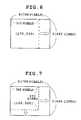
- FIG. 6is a view showing an information amount conversion for an image obtained using a CCD with 270 thousand pixels according to the embodiment
- FIG. 7is a view showing an information amount conversion for an image obtained using a CCD with 190 thousand pixels according to the embodiment.
- FIGS. 8 (A) to 8 (C)are views showing examples of configurations of conventional CCDs with different numbers of pixels.
- FIG. 1shows a configuration of an electronic endoscope apparatus according to an embodiment of the present invention.
- an electronic endoscope 10is connected to a processor device 12 .
- the electronic endoscope 10has a CCD 15 provided at a tip thereof via an objective optical system 14 .
- the CCD 15has 410 thousand, 270 thousand, 190 thousand or another number of pixels.
- the electronic endoscopehas a CDS/AGC circuit 16 or the like arranged therein to execute correlation double sampling (CDS) and automatic gain control (AGC) on output signals from the CCD 15 .
- the electronic endoscopealso has a ROM (EEPROM) 17 storing data or the like which identifies the number of pixels in the CCD 15 so that the data in the ROM 17 is transmitted to the processor device 12 upon power-on or the like.
- EEPROMROM
- the processor device 12is provided with an A/D converter 19 that receives an output signal from the CDS/AGC circuit 16 and a CCD driving and video signal processing circuit 20 that generates a drive signal for the CCD 15 and executes various processes such as color conversion, gamma correction, and contour emphasis on an output signal from the CCD 15 .
- the CCD driving and video signal processing circuit 20is provided with a timing generator (TG) having an oscillator to generate a 14.32-MHz pixel driving frequency used for the CCD 15 with 410 thousand pixels and to provide various timing signals such as a 15.734-kHz horizontal synchronizing signal, a 59.94-Hz vertical synchronizing signal, and other sampling frequencies all of which are formed from this oscillation frequency.
- TGtiming generator
- the CCD driving and video signal processing circuit 20is followed by an original image memory 21 that directly stores an output video signal from the circuit 20 , an information amount converting circuit 22 that compensates for the amount of pixel information (executes an interpolation process) when the CCD 15 having pixels the number of which is not 410 thousand is connected to the apparatus, and a converted image memory 23 that stores a video signal on which information amount conversion has been executed.
- the processor deviceis also provided with a microcomputer 25 that controls the information amount conversion and unifies and controls the circuits as well as a ROM (EEPROM) 26 .
- the information amount converting circuit 22is followed by a D/A converter 27 , a buffer 28 , and others. A video signal output from the buffer 28 is supplied to the monitor.
- the information amount converting circuit 22is internally provided with an image enlarging circuit 30 that enlarges an image on the basis of image data output from the original image memory 21 , using, for example, a pixel interpolating process that averages peripheral pixel data, a binarization circuit 31 that forms a binarized image from image data output from the original image memory 21 , a binary image enlarging circuit 32 that enlarges the binarized image using a pixel interpolating process, a factor calculating circuit 33 that multiplies a weighting factor on the basis of an average value for peripheral pixels obtained by the image enlarging circuit 30 , and an addition circuit 34 that adds an output from the factor calculating circuit 33 and an output from the image enlarging circuit 30 together.
- an image enlarging circuit 30that enlarges an image on the basis of image data output from the original image memory 21 , using, for example, a pixel interpolating process that averages peripheral pixel data, a binarization circuit 31 that
- the image enlarging circuit 30uses a nearest neighbor method of determining the average value of horizontal and vertical pixel (signal) levels of pixels adjacent to a pixel to be interpolated, but may use a bilinear method of determining the average value of the horizontal pixel levels. Further, if for example, 256 pixel levels are used, the binarization circuit 31 uses an intermediate value as a threshold to convert levels lower than level 128 into 0 and level 128 and higher levels into 1 (if 10 pixel levels are used, levels lower than level 5 are converted into 0, while level 5 and higher levels are converted into 1), and the binary image enlarging circuit 32 enlarges this binary image using an interpolation process. This interpolation may be the nearest neighbor method, the bilinear method, or a bicubic method for simple enlargement based on the direct insertion of values for adjacent pixel levels.
- the embodimentis constructed as described above, and its operation will be described below.
- the processor device 12when the processor device 12 is powered on, it communicates with the electronic endoscope 10 (ROM 17 ) to allow the microcomputer 25 to determine the number of pixels in the CCD 15 .
- the CCD 15 of the electronic endoscope 10is supplied with the 14.32-MHz pixel driving frequency formed by the CCD driving and video signal processing circuit 20 as well as a horizontal and vertical synchronizing signals and other signals formed on the basis of this frequency. Charges accumulated as pixels are read out from the CCD 15 at this frequency as image data.
- the CDS/AGC circuit 16is supplied with a sampling frequency or the like, and a video signal sampled and amplified in this circuit is provided to a signal processing section of the CCD driving and video signal processing circuit 20 via the A/D converter 19 .
- the signal processing sectionexecutes color conversion, gamma correction, or another process required to form a video.
- an output from the CCD driving and video signal processing circuit 20is supplied to the information amount converting circuit 22 .
- the converting circuit 22does not execute information amount conversion. That is, the video signal is stored in the original image memory 21 and then output to the monitor via the D/A converter 27 and buffer 28 .
- the monitordisplays a video of a subject picked up by the CCD 15 with 410 thousand pixels.
- the information amount converting circuit 22uses the steps shown in FIG. 2 to execute information amount conversion for enlargement. That is, the output from the CCD driving and video signal processing circuit 20 is stored in the original image memory 21 for each field, and subsequently one field of the image is read out therefrom (step 101 in FIG. 2 ).
- the image enlarging circuit 30executes pixel interpolation on this image in the horizontal and vertical directions on the basis of pixel averaging (step 102 ).
- FIGS. 3 (A) to 3 (C)show an averaging operation performed on peripheral pixels by the image enlarging circuit 30 and binary value enlarging circuit 32 .
- an averaging operationis performed on pixels located horizontally and obliquely adjacent to target pixels.
- the calculation p 3(p 2 +p 4 +p 8 +p 10 )/4 is executed
- the calculation p 6(p 5 +p 11 )/2 is executed.
- FIGS. 4 (A) to 4 (C)show a pixel interpolating process on the pixel p 3 , located in the upper part of FIG. 3 (A). If ten signal levels are used for simplification and pixels around the p 3 have values of 2, 6, 6, and 8, as shown in FIG. 4 (A), then the image enlarging circuit 30 obtains an average value of 5.5.
- the binarization circuit 31 in FIG. 1binarizes original image data (step 103 in FIG. 2 ), and the subsequent binary image enlarging circuit 32 interpolates and enlarges the binary image (step 104 in FIG. 2 ).
- the subsequent factor calculating circuit 33multiplies this binary data by a weighting factor and adds the result to an output from the image enlarging circuit 30 (step 105 in FIG. 2 ).
- FIGS. 5 (A) to 5 (C)show a pixel interpolating process executed on the pixel p 9 , located in the center of the image P in FIG. 3 (A).
- the image enlarging circuit 30obtains an average value of 6.5 for the pixel p 9 as shown in FIG. 5 (A).
- the weighting factor in the above embodimentis not the average value for all the peripheral pixels but for example, an average value for only pixels having a pixel value larger than a threshold such as an intermediate value.
- a thresholdsuch as an intermediate value.
- the information amount converting circuit 22increases the amount of information only in the horizontal direction. This is shown in FIG. 6 , and the 510 pixels in the horizontal direction are increased to 768 in the above-described manner. On the other hand, 492 lines are present in the vertical direction and thus the difference between this number and the corresponding number for the 410 thousand pixels is only two, so that this value is used as it is. Then, an image with an aspect ratio of 3 (vertical direction):4 (horizontal direction) can be displayed on the monitor.
- the information amount converting circuit 22increases the amount of information in not only horizontal but also vertical directions on the basis of pixel interpolation.
- This vertical pixel interpolationis similarly carried out using the method shown in FIGS. 4 and 5 . This is shown in FIG. 7 , and the 362 pixels in the horizontal direction are increased to 768, with 492 lines increased to 494. Then, likewise, an image with an aspect ratio of 3:4 can be displayed on the monitor.
- the threshold valueis the intermediate value of the signal level, and levels smaller than this intermediate value are set to 0, whereas levels equal to or larger than it are set to 1.
- the level of the characterizationcan be adjusted in a manner different from that with the above weighting factor.
- an electronic endoscope having an image pickup element with pixels the number of which is different from a reference pixel numberis connected to the electronic endoscope apparatus, a characteristic value for peripheral pixel information is extracted by using pixel interpolation, to form a video with a predetermined aspect ratio. Consequently, video processing can be easily executed by using image pickup elements with different numbers of pixels, while making the frequency for CCD driving and signal processing independent of the number of pixels, thereby eliminating the needs for complicated circuits or processes.
- data on a pixel to be interpolatedis calculated by using an interpolation process based on the averaging of peripheral pixels, and enlarged binary data is obtained for this target pixel. Then, a weighting factor is applied to this binary data, and the resultant data is added to the target pixel data. Consequently, an image obtained by using an image pickup device with a small number of pixels can be reproduced so as to appear equivalent to one obtained by using an image pickup device with a large number of pixels, thereby providing a video that is easy to observe and is free from jags.
Landscapes
- Engineering & Computer Science (AREA)
- Multimedia (AREA)
- Signal Processing (AREA)
- Physics & Mathematics (AREA)
- General Physics & Mathematics (AREA)
- Theoretical Computer Science (AREA)
- Endoscopes (AREA)
- Closed-Circuit Television Systems (AREA)
- Studio Devices (AREA)
- Instruments For Viewing The Inside Of Hollow Bodies (AREA)
- Image Processing (AREA)
Abstract
Description
Claims (4)
Applications Claiming Priority (2)
| Application Number | Priority Date | Filing Date | Title |
|---|---|---|---|
| JP2001102275AJP3962553B2 (en) | 2001-03-30 | 2001-03-30 | Electronic endoscope device |
| JP2001-102275 | 2001-03-30 |
Publications (2)
| Publication Number | Publication Date |
|---|---|
| US20020140807A1 US20020140807A1 (en) | 2002-10-03 |
| US6943821B2true US6943821B2 (en) | 2005-09-13 |
Family
ID=18955493
Family Applications (1)
| Application Number | Title | Priority Date | Filing Date |
|---|---|---|---|
| US10/101,345Expired - Fee RelatedUS6943821B2 (en) | 2001-03-30 | 2002-03-20 | Electronic endoscope apparatus to which electronic endoscopes with different numbers of pixels can be connected |
Country Status (3)
| Country | Link |
|---|---|
| US (1) | US6943821B2 (en) |
| JP (1) | JP3962553B2 (en) |
| DE (1) | DE10212915B4 (en) |
Cited By (45)
| Publication number | Priority date | Publication date | Assignee | Title |
|---|---|---|---|---|
| US20030215159A1 (en)* | 2002-04-26 | 2003-11-20 | Yoshiaki Okuno | Image processing device including pixel interpolation |
| US20050075538A1 (en)* | 2003-04-01 | 2005-04-07 | Banik Michael S. | Single use endoscopic imaging system |
| US20050078883A1 (en)* | 2003-10-08 | 2005-04-14 | Yi Jong-Hyon | Digital image processing device and method |
| US20050131279A1 (en)* | 2003-04-01 | 2005-06-16 | Boston Scientific Scimed, Inc. | Articulation joint for video endoscope |
| US20060069306A1 (en)* | 2004-09-30 | 2006-03-30 | Banik Michael S | Automated control of irrigation and aspiration in a single-use endoscope |
| US7578786B2 (en) | 2003-04-01 | 2009-08-25 | Boston Scientific Scimed, Inc. | Video endoscope |
| US7597662B2 (en) | 2004-09-30 | 2009-10-06 | Boston Scientific Scimed, Inc. | Multi-fluid delivery system |
| US7955255B2 (en) | 2006-04-20 | 2011-06-07 | Boston Scientific Scimed, Inc. | Imaging assembly with transparent distal cap |
| US8083671B2 (en) | 2004-09-30 | 2011-12-27 | Boston Scientific Scimed, Inc. | Fluid delivery system for use with an endoscope |
| US8118732B2 (en) | 2003-04-01 | 2012-02-21 | Boston Scientific Scimed, Inc. | Force feedback control system for video endoscope |
| US8199187B2 (en) | 2004-09-30 | 2012-06-12 | Boston Scientific Scimed, Inc. | Adapter for use with digital imaging medical device |
| US8202265B2 (en) | 2006-04-20 | 2012-06-19 | Boston Scientific Scimed, Inc. | Multiple lumen assembly for use in endoscopes or other medical devices |
| US8535219B2 (en) | 2003-04-01 | 2013-09-17 | Boston Scientific Scimed, Inc. | Fluid manifold for endoscope system |
| US20140211852A1 (en)* | 2001-07-11 | 2014-07-31 | Dolby Laboratories Licensing Corporation | Switch-Select Single Frame Reference |
| US8926502B2 (en) | 2011-03-07 | 2015-01-06 | Endochoice, Inc. | Multi camera endoscope having a side service channel |
| US9101266B2 (en) | 2011-02-07 | 2015-08-11 | Endochoice Innovation Center Ltd. | Multi-element cover for a multi-camera endoscope |
| US9101268B2 (en) | 2009-06-18 | 2015-08-11 | Endochoice Innovation Center Ltd. | Multi-camera endoscope |
| US9101287B2 (en) | 2011-03-07 | 2015-08-11 | Endochoice Innovation Center Ltd. | Multi camera endoscope assembly having multiple working channels |
| US9314147B2 (en) | 2011-12-13 | 2016-04-19 | Endochoice Innovation Center Ltd. | Rotatable connector for an endoscope |
| US9320419B2 (en) | 2010-12-09 | 2016-04-26 | Endochoice Innovation Center Ltd. | Fluid channeling component of a multi-camera endoscope |
| US9402533B2 (en) | 2011-03-07 | 2016-08-02 | Endochoice Innovation Center Ltd. | Endoscope circuit board assembly |
| US9492063B2 (en) | 2009-06-18 | 2016-11-15 | Endochoice Innovation Center Ltd. | Multi-viewing element endoscope |
| US9554692B2 (en) | 2009-06-18 | 2017-01-31 | EndoChoice Innovation Ctr. Ltd. | Multi-camera endoscope |
| US9560954B2 (en) | 2012-07-24 | 2017-02-07 | Endochoice, Inc. | Connector for use with endoscope |
| US9560953B2 (en) | 2010-09-20 | 2017-02-07 | Endochoice, Inc. | Operational interface in a multi-viewing element endoscope |
| US9642513B2 (en) | 2009-06-18 | 2017-05-09 | Endochoice Inc. | Compact multi-viewing element endoscope system |
| US9655502B2 (en) | 2011-12-13 | 2017-05-23 | EndoChoice Innovation Center, Ltd. | Removable tip endoscope |
| US9706903B2 (en) | 2009-06-18 | 2017-07-18 | Endochoice, Inc. | Multiple viewing elements endoscope system with modular imaging units |
| US9713417B2 (en) | 2009-06-18 | 2017-07-25 | Endochoice, Inc. | Image capture assembly for use in a multi-viewing elements endoscope |
| US9814374B2 (en) | 2010-12-09 | 2017-11-14 | Endochoice Innovation Center Ltd. | Flexible electronic circuit board for a multi-camera endoscope |
| US9872609B2 (en) | 2009-06-18 | 2018-01-23 | Endochoice Innovation Center Ltd. | Multi-camera endoscope |
| US9901244B2 (en) | 2009-06-18 | 2018-02-27 | Endochoice, Inc. | Circuit board assembly of a multiple viewing elements endoscope |
| US9986899B2 (en) | 2013-03-28 | 2018-06-05 | Endochoice, Inc. | Manifold for a multiple viewing elements endoscope |
| US9993142B2 (en) | 2013-03-28 | 2018-06-12 | Endochoice, Inc. | Fluid distribution device for a multiple viewing elements endoscope |
| US10080486B2 (en) | 2010-09-20 | 2018-09-25 | Endochoice Innovation Center Ltd. | Multi-camera endoscope having fluid channels |
| US10165929B2 (en) | 2009-06-18 | 2019-01-01 | Endochoice, Inc. | Compact multi-viewing element endoscope system |
| US10203493B2 (en) | 2010-10-28 | 2019-02-12 | Endochoice Innovation Center Ltd. | Optical systems for multi-sensor endoscopes |
| US10499794B2 (en) | 2013-05-09 | 2019-12-10 | Endochoice, Inc. | Operational interface in a multi-viewing element endoscope |
| US11278190B2 (en) | 2009-06-18 | 2022-03-22 | Endochoice, Inc. | Multi-viewing element endoscope |
| US11547275B2 (en) | 2009-06-18 | 2023-01-10 | Endochoice, Inc. | Compact multi-viewing element endoscope system |
| US11864734B2 (en) | 2009-06-18 | 2024-01-09 | Endochoice, Inc. | Multi-camera endoscope |
| US11889986B2 (en) | 2010-12-09 | 2024-02-06 | Endochoice, Inc. | Flexible electronic circuit board for a multi-camera endoscope |
| US12137873B2 (en) | 2009-06-18 | 2024-11-12 | Endochoice, Inc. | Compact multi-viewing element endoscope system |
| US12204087B2 (en) | 2010-10-28 | 2025-01-21 | Endochoice, Inc. | Optical systems for multi-sensor endoscopes |
| US12220105B2 (en) | 2010-06-16 | 2025-02-11 | Endochoice, Inc. | Circuit board assembly of a multiple viewing elements endoscope |
Families Citing this family (2)
| Publication number | Priority date | Publication date | Assignee | Title |
|---|---|---|---|---|
| JP5202225B2 (en)* | 2008-10-17 | 2013-06-05 | キヤノン株式会社 | Imaging apparatus and control method thereof |
| WO2018109981A1 (en)* | 2016-12-15 | 2018-06-21 | オリンパス株式会社 | Endoscope and endoscope system |
Citations (3)
| Publication number | Priority date | Publication date | Assignee | Title |
|---|---|---|---|---|
| US4891695A (en)* | 1988-02-23 | 1990-01-02 | Olympus Optical Co. Ltd. | Electronic endoscope apparatus provided with a plurality of endoscopes having solid state imaging devices with at least one identical pixel forming element |
| US4894715A (en)* | 1988-01-08 | 1990-01-16 | Olympus Optical Co., Ltd. | Electronic endoscope |
| US5627583A (en)* | 1992-02-07 | 1997-05-06 | Olympus Optical Co., Ltd. | Electroendoscope apparatus |
- 2001
- 2001-03-30JPJP2001102275Apatent/JP3962553B2/ennot_activeExpired - Fee Related
- 2002
- 2002-03-20USUS10/101,345patent/US6943821B2/ennot_activeExpired - Fee Related
- 2002-03-22DEDE10212915Apatent/DE10212915B4/ennot_activeExpired - Fee Related
Patent Citations (3)
| Publication number | Priority date | Publication date | Assignee | Title |
|---|---|---|---|---|
| US4894715A (en)* | 1988-01-08 | 1990-01-16 | Olympus Optical Co., Ltd. | Electronic endoscope |
| US4891695A (en)* | 1988-02-23 | 1990-01-02 | Olympus Optical Co. Ltd. | Electronic endoscope apparatus provided with a plurality of endoscopes having solid state imaging devices with at least one identical pixel forming element |
| US5627583A (en)* | 1992-02-07 | 1997-05-06 | Olympus Optical Co., Ltd. | Electroendoscope apparatus |
Cited By (96)
| Publication number | Priority date | Publication date | Assignee | Title |
|---|---|---|---|---|
| US8995528B2 (en)* | 2001-07-11 | 2015-03-31 | Dolby Laboratories Licensing Corporation | Switch-select single frame reference |
| US8942285B2 (en) | 2001-07-11 | 2015-01-27 | Dolby Laboratories Licensing Corporation | Motion compensation filtering in an image system |
| US20140211852A1 (en)* | 2001-07-11 | 2014-07-31 | Dolby Laboratories Licensing Corporation | Switch-Select Single Frame Reference |
| US7346231B2 (en)* | 2002-04-26 | 2008-03-18 | Mitsubishi Denki Kabushiki Kaisha | Image processing device including pixel interpolation |
| US20030215159A1 (en)* | 2002-04-26 | 2003-11-20 | Yoshiaki Okuno | Image processing device including pixel interpolation |
| US8608648B2 (en) | 2003-04-01 | 2013-12-17 | Boston Scientific Scimed, Inc. | Articulation joint |
| US9913573B2 (en) | 2003-04-01 | 2018-03-13 | Boston Scientific Scimed, Inc. | Endoscopic imaging system |
| US8535219B2 (en) | 2003-04-01 | 2013-09-17 | Boston Scientific Scimed, Inc. | Fluid manifold for endoscope system |
| US20050075538A1 (en)* | 2003-04-01 | 2005-04-07 | Banik Michael S. | Single use endoscopic imaging system |
| US7578786B2 (en) | 2003-04-01 | 2009-08-25 | Boston Scientific Scimed, Inc. | Video endoscope |
| US7591783B2 (en) | 2003-04-01 | 2009-09-22 | Boston Scientific Scimed, Inc. | Articulation joint for video endoscope |
| US8475366B2 (en) | 2003-04-01 | 2013-07-02 | Boston Scientific Scimed, Inc. | Articulation joint for a medical device |
| US8622894B2 (en) | 2003-04-01 | 2014-01-07 | Boston Scientific Scimed, Inc. | Articulation joint |
| US11324395B2 (en) | 2003-04-01 | 2022-05-10 | Boston Scientific Scimed, Inc. | Endoscopic imaging system |
| US8118732B2 (en) | 2003-04-01 | 2012-02-21 | Boston Scientific Scimed, Inc. | Force feedback control system for video endoscope |
| US10765307B2 (en) | 2003-04-01 | 2020-09-08 | Boston Scientific Scimed, Inc. | Endoscopic imaging system |
| US7413543B2 (en) | 2003-04-01 | 2008-08-19 | Scimed Life Systems, Inc. | Endoscope with actively cooled illumination sources |
| US8425408B2 (en) | 2003-04-01 | 2013-04-23 | Boston Scientific Scimed, Inc. | Articulation joint for video endoscope |
| US20050131279A1 (en)* | 2003-04-01 | 2005-06-16 | Boston Scientific Scimed, Inc. | Articulation joint for video endoscope |
| US20050078883A1 (en)* | 2003-10-08 | 2005-04-14 | Yi Jong-Hyon | Digital image processing device and method |
| US7437020B2 (en)* | 2003-10-08 | 2008-10-14 | Samsung Electronics Co., Ltd. | Digital image processing device and method |
| USRE46007E1 (en) | 2004-09-30 | 2016-05-24 | Boston Scientific Scimed, Inc. | Automated control of irrigation and aspiration in a single-use endoscope |
| US20060069306A1 (en)* | 2004-09-30 | 2006-03-30 | Banik Michael S | Automated control of irrigation and aspiration in a single-use endoscope |
| US8435172B2 (en) | 2004-09-30 | 2013-05-07 | Boston Scientific Scimed, Inc. | Automated control of irrigation and aspiration in a single-use endoscope |
| US8199187B2 (en) | 2004-09-30 | 2012-06-12 | Boston Scientific Scimed, Inc. | Adapter for use with digital imaging medical device |
| US8083671B2 (en) | 2004-09-30 | 2011-12-27 | Boston Scientific Scimed, Inc. | Fluid delivery system for use with an endoscope |
| US7597662B2 (en) | 2004-09-30 | 2009-10-06 | Boston Scientific Scimed, Inc. | Multi-fluid delivery system |
| US7479106B2 (en) | 2004-09-30 | 2009-01-20 | Boston Scientific Scimed, Inc. | Automated control of irrigation and aspiration in a single-use endoscope |
| US8202265B2 (en) | 2006-04-20 | 2012-06-19 | Boston Scientific Scimed, Inc. | Multiple lumen assembly for use in endoscopes or other medical devices |
| US8870753B2 (en) | 2006-04-20 | 2014-10-28 | Boston Scientific Scimed, Inc. | Imaging assembly with transparent distal cap |
| US7955255B2 (en) | 2006-04-20 | 2011-06-07 | Boston Scientific Scimed, Inc. | Imaging assembly with transparent distal cap |
| US9358363B2 (en) | 2006-04-20 | 2016-06-07 | Boston Scientific Scimed, Inc. | Multiple lumen assembly for use in endoscopes or other medical devices |
| US10912445B2 (en) | 2009-06-18 | 2021-02-09 | Endochoice, Inc. | Compact multi-viewing element endoscope system |
| US11864734B2 (en) | 2009-06-18 | 2024-01-09 | Endochoice, Inc. | Multi-camera endoscope |
| US11471028B2 (en) | 2009-06-18 | 2022-10-18 | Endochoice, Inc. | Circuit board assembly of a multiple viewing elements endoscope |
| US12336686B2 (en) | 2009-06-18 | 2025-06-24 | Endochoice, Inc. | Multi-viewing element endoscope |
| US12303106B2 (en) | 2009-06-18 | 2025-05-20 | Endochoice, Inc. | Multi-camera endoscope |
| US9492063B2 (en) | 2009-06-18 | 2016-11-15 | Endochoice Innovation Center Ltd. | Multi-viewing element endoscope |
| US9554692B2 (en) | 2009-06-18 | 2017-01-31 | EndoChoice Innovation Ctr. Ltd. | Multi-camera endoscope |
| US10905320B2 (en) | 2009-06-18 | 2021-02-02 | Endochoice, Inc. | Multi-camera endoscope |
| US10799095B2 (en) | 2009-06-18 | 2020-10-13 | Endochoice, Inc. | Multi-viewing element endoscope |
| US9642513B2 (en) | 2009-06-18 | 2017-05-09 | Endochoice Inc. | Compact multi-viewing element endoscope system |
| US10791910B2 (en) | 2009-06-18 | 2020-10-06 | Endochoice, Inc. | Multiple viewing elements endoscope system with modular imaging units |
| US9706903B2 (en) | 2009-06-18 | 2017-07-18 | Endochoice, Inc. | Multiple viewing elements endoscope system with modular imaging units |
| US9706905B2 (en) | 2009-06-18 | 2017-07-18 | Endochoice Innovation Center Ltd. | Multi-camera endoscope |
| US9713417B2 (en) | 2009-06-18 | 2017-07-25 | Endochoice, Inc. | Image capture assembly for use in a multi-viewing elements endoscope |
| US12137873B2 (en) | 2009-06-18 | 2024-11-12 | Endochoice, Inc. | Compact multi-viewing element endoscope system |
| US10791909B2 (en) | 2009-06-18 | 2020-10-06 | Endochoice, Inc. | Image capture assembly for use in a multi-viewing elements endoscope |
| US11986155B2 (en) | 2009-06-18 | 2024-05-21 | Endochoice, Inc. | Multi-viewing element endoscope |
| US9872609B2 (en) | 2009-06-18 | 2018-01-23 | Endochoice Innovation Center Ltd. | Multi-camera endoscope |
| US9901244B2 (en) | 2009-06-18 | 2018-02-27 | Endochoice, Inc. | Circuit board assembly of a multiple viewing elements endoscope |
| US9101268B2 (en) | 2009-06-18 | 2015-08-11 | Endochoice Innovation Center Ltd. | Multi-camera endoscope |
| US10765305B2 (en) | 2009-06-18 | 2020-09-08 | Endochoice, Inc. | Circuit board assembly of a multiple viewing elements endoscope |
| US11278190B2 (en) | 2009-06-18 | 2022-03-22 | Endochoice, Inc. | Multi-viewing element endoscope |
| US11547275B2 (en) | 2009-06-18 | 2023-01-10 | Endochoice, Inc. | Compact multi-viewing element endoscope system |
| US10638922B2 (en) | 2009-06-18 | 2020-05-05 | Endochoice, Inc. | Multi-camera endoscope |
| US11534056B2 (en) | 2009-06-18 | 2022-12-27 | Endochoice, Inc. | Multi-camera endoscope |
| US10092167B2 (en) | 2009-06-18 | 2018-10-09 | Endochoice, Inc. | Multiple viewing elements endoscope system with modular imaging units |
| US10165929B2 (en) | 2009-06-18 | 2019-01-01 | Endochoice, Inc. | Compact multi-viewing element endoscope system |
| US12220105B2 (en) | 2010-06-16 | 2025-02-11 | Endochoice, Inc. | Circuit board assembly of a multiple viewing elements endoscope |
| US10080486B2 (en) | 2010-09-20 | 2018-09-25 | Endochoice Innovation Center Ltd. | Multi-camera endoscope having fluid channels |
| US9560953B2 (en) | 2010-09-20 | 2017-02-07 | Endochoice, Inc. | Operational interface in a multi-viewing element endoscope |
| US9986892B2 (en) | 2010-09-20 | 2018-06-05 | Endochoice, Inc. | Operational interface in a multi-viewing element endoscope |
| US12204087B2 (en) | 2010-10-28 | 2025-01-21 | Endochoice, Inc. | Optical systems for multi-sensor endoscopes |
| US10203493B2 (en) | 2010-10-28 | 2019-02-12 | Endochoice Innovation Center Ltd. | Optical systems for multi-sensor endoscopes |
| US11543646B2 (en) | 2010-10-28 | 2023-01-03 | Endochoice, Inc. | Optical systems for multi-sensor endoscopes |
| US11497388B2 (en) | 2010-12-09 | 2022-11-15 | Endochoice, Inc. | Flexible electronic circuit board for a multi-camera endoscope |
| US9814374B2 (en) | 2010-12-09 | 2017-11-14 | Endochoice Innovation Center Ltd. | Flexible electronic circuit board for a multi-camera endoscope |
| US11889986B2 (en) | 2010-12-09 | 2024-02-06 | Endochoice, Inc. | Flexible electronic circuit board for a multi-camera endoscope |
| US10898063B2 (en) | 2010-12-09 | 2021-01-26 | Endochoice, Inc. | Flexible electronic circuit board for a multi camera endoscope |
| US10182707B2 (en) | 2010-12-09 | 2019-01-22 | Endochoice Innovation Center Ltd. | Fluid channeling component of a multi-camera endoscope |
| US9320419B2 (en) | 2010-12-09 | 2016-04-26 | Endochoice Innovation Center Ltd. | Fluid channeling component of a multi-camera endoscope |
| US10070774B2 (en) | 2011-02-07 | 2018-09-11 | Endochoice Innovation Center Ltd. | Multi-element cover for a multi-camera endoscope |
| US9351629B2 (en) | 2011-02-07 | 2016-05-31 | Endochoice Innovation Center Ltd. | Multi-element cover for a multi-camera endoscope |
| US9101266B2 (en) | 2011-02-07 | 2015-08-11 | Endochoice Innovation Center Ltd. | Multi-element cover for a multi-camera endoscope |
| US8926502B2 (en) | 2011-03-07 | 2015-01-06 | Endochoice, Inc. | Multi camera endoscope having a side service channel |
| US10292578B2 (en) | 2011-03-07 | 2019-05-21 | Endochoice Innovation Center Ltd. | Multi camera endoscope assembly having multiple working channels |
| US9402533B2 (en) | 2011-03-07 | 2016-08-02 | Endochoice Innovation Center Ltd. | Endoscope circuit board assembly |
| US9713415B2 (en) | 2011-03-07 | 2017-07-25 | Endochoice Innovation Center Ltd. | Multi camera endoscope having a side service channel |
| US9854959B2 (en) | 2011-03-07 | 2018-01-02 | Endochoice Innovation Center Ltd. | Multi camera endoscope assembly having multiple working channels |
| US9101287B2 (en) | 2011-03-07 | 2015-08-11 | Endochoice Innovation Center Ltd. | Multi camera endoscope assembly having multiple working channels |
| US11026566B2 (en) | 2011-03-07 | 2021-06-08 | Endochoice, Inc. | Multi camera endoscope assembly having multiple working channels |
| US10470649B2 (en) | 2011-12-13 | 2019-11-12 | Endochoice, Inc. | Removable tip endoscope |
| US9655502B2 (en) | 2011-12-13 | 2017-05-23 | EndoChoice Innovation Center, Ltd. | Removable tip endoscope |
| US9314147B2 (en) | 2011-12-13 | 2016-04-19 | Endochoice Innovation Center Ltd. | Rotatable connector for an endoscope |
| US11291357B2 (en) | 2011-12-13 | 2022-04-05 | Endochoice, Inc. | Removable tip endoscope |
| US12290241B2 (en) | 2011-12-13 | 2025-05-06 | Endochoice, Inc. | Removable tip endoscope |
| US9560954B2 (en) | 2012-07-24 | 2017-02-07 | Endochoice, Inc. | Connector for use with endoscope |
| US12232699B2 (en) | 2013-03-28 | 2025-02-25 | Endochoice, Inc. | Manifold for a multiple viewing elements endoscope |
| US10925471B2 (en) | 2013-03-28 | 2021-02-23 | Endochoice, Inc. | Fluid distribution device for a multiple viewing elements endoscope |
| US10905315B2 (en) | 2013-03-28 | 2021-02-02 | Endochoice, Inc. | Manifold for a multiple viewing elements endoscope |
| US11925323B2 (en) | 2013-03-28 | 2024-03-12 | Endochoice, Inc. | Fluid distribution device for a multiple viewing elements endoscope |
| US9993142B2 (en) | 2013-03-28 | 2018-06-12 | Endochoice, Inc. | Fluid distribution device for a multiple viewing elements endoscope |
| US9986899B2 (en) | 2013-03-28 | 2018-06-05 | Endochoice, Inc. | Manifold for a multiple viewing elements endoscope |
| US11793393B2 (en) | 2013-03-28 | 2023-10-24 | Endochoice, Inc. | Manifold for a multiple viewing elements endoscope |
| US10499794B2 (en) | 2013-05-09 | 2019-12-10 | Endochoice, Inc. | Operational interface in a multi-viewing element endoscope |
Also Published As
| Publication number | Publication date |
|---|---|
| DE10212915A1 (en) | 2002-10-10 |
| JP2002300574A (en) | 2002-10-11 |
| DE10212915B4 (en) | 2010-07-01 |
| US20020140807A1 (en) | 2002-10-03 |
| JP3962553B2 (en) | 2007-08-22 |
Similar Documents
| Publication | Publication Date | Title |
|---|---|---|
| US6943821B2 (en) | Electronic endoscope apparatus to which electronic endoscopes with different numbers of pixels can be connected | |
| US6876380B2 (en) | Electronic endoscopic apparatus connectable with electronic endoscope having different number of pixels | |
| JP3949903B2 (en) | Imaging apparatus and imaging signal processing method | |
| US6995786B2 (en) | Electronic endoscope forming still image by double-speed reading | |
| JPH10150668A (en) | Imaging device and method of processing color image signal | |
| JP4607006B2 (en) | Video signal processing method and video signal processing apparatus | |
| US7382402B2 (en) | Imaging system | |
| JP2010117884A (en) | Image processing device, video display apparatus, imaging apparatus and image processing method | |
| JP2003219205A (en) | Imaging device, display device, image recording device, and image quality correction method | |
| JP4900265B2 (en) | Image processing apparatus, image processing method, and program | |
| JP2006148496A (en) | Circuit and method of correcting focal plane distortion, electronic apparatus, program and recording medium | |
| JP2000092379A (en) | Imaging apparatus, exposure control method thereof, and recording medium | |
| US7203357B2 (en) | Image data processor and image data processing method | |
| JP2007194832A (en) | Tone correction device | |
| US20110063475A1 (en) | Image pick-up apparatus and recording medium storing computer program of the apparatus | |
| JP2006157450A (en) | Imaging apparatus and image processing method | |
| JP2001268400A (en) | Histogram creation device and histogram creation method | |
| JP2003153093A (en) | Solid-state imaging device, electronic still camera, method for driving solid-state image pickup element and control program for driving the solid-state image pickup element | |
| JP2001209782A (en) | Image capturing apparatus and character image capturing method thereof | |
| JP2008076878A (en) | IMAGING DEVICE, IMAGING DEVICE CONTROL METHOD, PROGRAM, AND STORAGE MEDIUM | |
| JP4099551B2 (en) | Video signal processing apparatus and video signal processing method | |
| JPH11308535A (en) | Image pickup device | |
| JPH05191674A (en) | Gradation correction device | |
| JP2001128058A (en) | Imaging device | |
| JP4869014B2 (en) | Pixel level detection circuit |
Legal Events
| Date | Code | Title | Description |
|---|---|---|---|
| AS | Assignment | Owner name:FUJI PHOTO OPTICAL CO., LTD., JAPAN Free format text:ASSIGNMENT OF ASSIGNORS INTEREST;ASSIGNORS:ABE, KAZUNORI;OKADA, FUJIO;REEL/FRAME:012717/0515 Effective date:20020226 | |
| AS | Assignment | Owner name:FUJINON CORPORATION, JAPAN Free format text:CHANGE OF NAME;ASSIGNOR:FUJI PHOTO OPTICAL CO., LTD.;REEL/FRAME:016549/0899 Effective date:20041001 Owner name:FUJINON CORPORATION,JAPAN Free format text:CHANGE OF NAME;ASSIGNOR:FUJI PHOTO OPTICAL CO., LTD.;REEL/FRAME:016549/0899 Effective date:20041001 | |
| FEPP | Fee payment procedure | Free format text:PAYOR NUMBER ASSIGNED (ORIGINAL EVENT CODE: ASPN); ENTITY STATUS OF PATENT OWNER: LARGE ENTITY Free format text:PAYER NUMBER DE-ASSIGNED (ORIGINAL EVENT CODE: RMPN); ENTITY STATUS OF PATENT OWNER: LARGE ENTITY | |
| FPAY | Fee payment | Year of fee payment:4 | |
| REMI | Maintenance fee reminder mailed | ||
| LAPS | Lapse for failure to pay maintenance fees | ||
| STCH | Information on status: patent discontinuation | Free format text:PATENT EXPIRED DUE TO NONPAYMENT OF MAINTENANCE FEES UNDER 37 CFR 1.362 | |
| FP | Lapsed due to failure to pay maintenance fee | Effective date:20130913 |