US6943749B2 - Printed circuit board dipole antenna structure with impedance matching trace - Google Patents
Printed circuit board dipole antenna structure with impedance matching traceDownload PDFInfo
- Publication number
- US6943749B2 US6943749B2US10/759,259US75925904AUS6943749B2US 6943749 B2US6943749 B2US 6943749B2US 75925904 AUS75925904 AUS 75925904AUS 6943749 B2US6943749 B2US 6943749B2
- Authority
- US
- United States
- Prior art keywords
- antenna
- impedance matching
- circuit board
- strip
- radiating
- Prior art date
- Legal status (The legal status is an assumption and is not a legal conclusion. Google has not performed a legal analysis and makes no representation as to the accuracy of the status listed.)
- Expired - Lifetime, expires
Links
- 230000005855radiationEffects0.000claimsabstractdescription11
- 230000005540biological transmissionEffects0.000claimsabstractdescription8
- 239000004020conductorSubstances0.000claimsdescription9
- 239000003989dielectric materialSubstances0.000claimsdescription6
- 239000000463materialSubstances0.000claimsdescription4
- WYTGDNHDOZPMIW-RCBQFDQVSA-NalstonineNatural productsC1=CC2=C3C=CC=CC3=NC2=C2N1C[C@H]1[C@H](C)OC=C(C(=O)OC)[C@H]1C2WYTGDNHDOZPMIW-RCBQFDQVSA-N0.000abstractdescription2
- 238000000576coating methodMethods0.000description7
- 239000011248coating agentSubstances0.000description6
- RYGMFSIKBFXOCR-UHFFFAOYSA-NCopperChemical compound[Cu]RYGMFSIKBFXOCR-UHFFFAOYSA-N0.000description4
- 229910052802copperInorganic materials0.000description4
- 239000010949copperSubstances0.000description4
- XLYOFNOQVPJJNP-UHFFFAOYSA-NwaterSubstancesOXLYOFNOQVPJJNP-UHFFFAOYSA-N0.000description3
- 238000010276constructionMethods0.000description1
- 230000003247decreasing effectEffects0.000description1
- 238000005516engineering processMethods0.000description1
- PCHJSUWPFVWCPO-UHFFFAOYSA-NgoldChemical compound[Au]PCHJSUWPFVWCPO-UHFFFAOYSA-N0.000description1
- 229910052737goldInorganic materials0.000description1
- 239000010931goldSubstances0.000description1
- 238000005259measurementMethods0.000description1
- 238000000034methodMethods0.000description1
- 238000012986modificationMethods0.000description1
- 230000004048modificationEffects0.000description1
- 238000012806monitoring deviceMethods0.000description1
- 230000001681protective effectEffects0.000description1
- 229910052709silverInorganic materials0.000description1
- 239000004332silverSubstances0.000description1
- 238000012360testing methodMethods0.000description1
Images


Classifications
- H—ELECTRICITY
- H01—ELECTRIC ELEMENTS
- H01Q—ANTENNAS, i.e. RADIO AERIALS
- H01Q9/00—Electrically-short antennas having dimensions not more than twice the operating wavelength and consisting of conductive active radiating elements
- H01Q9/04—Resonant antennas
- H01Q9/16—Resonant antennas with feed intermediate between the extremities of the antenna, e.g. centre-fed dipole
- H01Q9/28—Conical, cylindrical, cage, strip, gauze, or like elements having an extended radiating surface; Elements comprising two conical surfaces having collinear axes and adjacent apices and fed by two-conductor transmission lines
- H—ELECTRICITY
- H01—ELECTRIC ELEMENTS
- H01Q—ANTENNAS, i.e. RADIO AERIALS
- H01Q1/00—Details of, or arrangements associated with, antennas
- H01Q1/36—Structural form of radiating elements, e.g. cone, spiral, umbrella; Particular materials used therewith
- H01Q1/38—Structural form of radiating elements, e.g. cone, spiral, umbrella; Particular materials used therewith formed by a conductive layer on an insulating support
- H—ELECTRICITY
- H01—ELECTRIC ELEMENTS
- H01Q—ANTENNAS, i.e. RADIO AERIALS
- H01Q1/00—Details of, or arrangements associated with, antennas
- H01Q1/12—Supports; Mounting means
- H01Q1/22—Supports; Mounting means by structural association with other equipment or articles
- H01Q1/2208—Supports; Mounting means by structural association with other equipment or articles associated with components used in interrogation type services, i.e. in systems for information exchange between an interrogator/reader and a tag/transponder, e.g. in Radio Frequency Identification [RFID] systems
- H01Q1/2233—Supports; Mounting means by structural association with other equipment or articles associated with components used in interrogation type services, i.e. in systems for information exchange between an interrogator/reader and a tag/transponder, e.g. in Radio Frequency Identification [RFID] systems used in consumption-meter devices, e.g. electricity, gas or water meters
- H—ELECTRICITY
- H01—ELECTRIC ELEMENTS
- H01Q—ANTENNAS, i.e. RADIO AERIALS
- H01Q23/00—Antennas with active circuits or circuit elements integrated within them or attached to them
- H—ELECTRICITY
- H01—ELECTRIC ELEMENTS
- H01Q—ANTENNAS, i.e. RADIO AERIALS
- H01Q9/00—Electrically-short antennas having dimensions not more than twice the operating wavelength and consisting of conductive active radiating elements
- H01Q9/04—Resonant antennas
- H01Q9/16—Resonant antennas with feed intermediate between the extremities of the antenna, e.g. centre-fed dipole
- H01Q9/28—Conical, cylindrical, cage, strip, gauze, or like elements having an extended radiating surface; Elements comprising two conical surfaces having collinear axes and adjacent apices and fed by two-conductor transmission lines
- H01Q9/285—Planar dipole
- H—ELECTRICITY
- H05—ELECTRIC TECHNIQUES NOT OTHERWISE PROVIDED FOR
- H05K—PRINTED CIRCUITS; CASINGS OR CONSTRUCTIONAL DETAILS OF ELECTRIC APPARATUS; MANUFACTURE OF ASSEMBLAGES OF ELECTRICAL COMPONENTS
- H05K1/00—Printed circuits
- H05K1/16—Printed circuits incorporating printed electric components, e.g. printed resistor, capacitor, inductor
Definitions
- the present inventiongenerally relates to the field of antennas for transmitting radio frequency signals. More particularly, the present invention relates to a printed antenna comprised of thin layers of electrically conductive material that are bonded onto a thin, planar dielectric material such as a printed circuit board (PCB) that also serves as a platform for an antenna driving circuit.
- PCBprinted circuit board
- antennas for transmitting radio frequency signals from a small, compact location to an external receiverhave grown significantly.
- antennas for transmitting radio frequency signals from a recording or monitoring devicesuch as a thermostat, water meter, gas meter, electric meter or any similar type of device to a remote location that is configured to monitor and record the status of the device have become increasingly desirable. Since many of the devices utilizing an RF antenna are produced in very large quantities, a desire and need exists for an antenna that can transmit the RF signals a desired distance while being low in cost to produce and assemble.
- an antenna structureis formed separate from the printed circuit board that includes the antenna driving circuit.
- the separate antenna deviceincreases the cost to produce the combination of the antenna and driving circuit while also increasing the size of the compartment needed to house the two separate components.
- a micro strip patch antennaincludes a dielectric material, such as a printed circuit board, which has two opposed surfaces. One of the surfaces is coated with an electrically conductive layer that functions as a ground plane and the opposed surface has an essentially rectangular or circular shaped electrically conductive layer (micro strip patch) disposed to extend over the ground plane.
- the micro strip patch antennapresents a thin resonating cavity where standing electromagnetic waves can exist and can be radiated from the edges of the antenna.
- Micro strip patch antennashave many limitations, including the ability to radiate only above the ground plane. Further, because the micro strip patch antenna has a resonant cavity that greatly depends upon the thickness of the dielectric material utilized, tuning such an antenna is difficult. Thus, the printed circuit board forms a important part of the antenna structure, even though a PCB is typically formulated with rather low tolerances.
- the present inventionseeks to provide a printed antenna that can be formed directly on a dielectric material, such as a printed circuit board, that also is used to mount the antenna driving circuitry. Further, the present invention seeks to provide a printed circuit antenna that functions as a dipole antenna having a radiating portion significantly less than one-half the wave length of the received/transmitted frequency range.
- the antennaalso provides an impedance matching strip that allow the antenna to match the impedance of the antenna driving circuit by increasing or decreasing the length and configuration of the impedance matching strip.
- the present inventionis a printed antenna for the transmission of electromagnetic waves, such as radio frequency signals, from an electrical device coupled to the printed antenna.
- the printed antenna of the present inventionis designed for use in communicating information from a measurement device, such as an electronic thermostat, gas meter, water meter, electric meter or similar device.
- a measurement devicesuch as an electronic thermostat, gas meter, water meter, electric meter or similar device.
- the printed antenna of the present inventioncan be utilized for transmitting information from any device that incorporates an antenna driving circuit mounted to a printed circuit board.
- the printed antenna of the present inventionincludes a substantially planar printed circuit board that is formed from a dielectric material.
- the printed circuit boardis a conventional component and is utilized to mount an antenna driving circuit that operates to generate electromagnetic waves for transmission and receives electromagnetic information from a remote transmission device.
- the circuit boardincludes a planar first surface and a planar second surface that are separated by a material thickness.
- the circuit boardis a unitary structure and is configured to include both a mounting section and an antenna section.
- the mounting section of the circuit boardincludes the antenna driving circuit for the printed antenna.
- the antenna driving circuitis mounted to the first surface of the circuit board within the mounting section.
- the second planar surface of the mounting section of the circuit boardincludes a coating of electrically conductive material that covers substantially all of the mounting section.
- the coating of electrically conductive material that defines the ground planeis positioned on the opposite side of the circuit board from the antenna driving circuit such that the antenna driving circuit is positioned opposite the area defined by the ground plane.
- the antenna section of the circuit boardincludes both a first antenna trace and a second antenna trace that form opposite halves of a one-half wavelength dipole antenna.
- Each of the antenna tracesis formed from an electrically conductive material printed onto the face surface of the circuit board.
- Each antenna traceincludes a connecting strip that couples the antenna trace to either ground or the active connection of the antenna driving circuit. Since the antenna traces are a mirror images of the opposite antenna trace, the configuration of each antenna trace is identical.
- Each antenna traceincludes a radiating strip extending from the connection strip.
- the combined length of the two radiating stripsis less than one-half the wavelength of the desired frequency that the antenna structure radiates and receives.
- each antenna tracealso includes an impedance matching strip coupled to the radiating strip.
- the impedance matching stripis a serpentine structure and is coupled to the radiating strip by a connecting trace.
- the connecting traceforms a connection between the radiating strip and the impedance matching strip and is configured depending upon the overall shape of the printed circuit board.
- the impedance matching stripis joined to the radiating strip to define a continuous length of electrically conductive material applied to the front face surface of the antenna section.
- the impedance matching stripis coupled to the radiating strip and has a length such that the impedance matching strip functions to match the impedance of the antenna driving circuit.
- the impedance matching stripincludes a plurality of parallel legs joined to each other and coupled to the radiating strip. Each leg of the impedance matching strip is parallel to the radiating strip. The legs of the impedance matching strip are joined to each other by connector portions such that the entire impedance matching strip is a continuous trace applied to the face surface of the antenna section.
- one of the legs of the impedance matching stripis shorter than the remaining legs such that the leg acts as a tuning stub.
- the length and characteristics of the tuning stubcan be adjusted to fine tune the impedance matching strip to the impedance requirement of the antenna driving circuit.
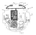
- FIG. 1is a front plan view of a printed circuit board including the printed dipole antenna of the present invention
- FIG. 2is a detailed illustration of the printed dipole antenna including an impedance matching strip
- FIG. 3is a section view taken along line 3 — 3 of FIG. 1 ;
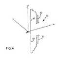
- FIG. 4is a perspective illustration showing the axes of rotation of the printed circuit board dipole antenna structure during radiation testing
- FIG. 5is a 3-D radiation pattern for the printed circuit board dipole antenna structure of the present invention.
- FIG. 6is a graphic illustration of the radiation pattern of the antenna of the present invention as rotated along the Z axis.
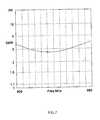
- FIG. 7is a graph illustration illustrating the SWR over a frequency range of 900 MHz to 960 MHz.
- the antenna driving circuit 14includes various electronic components for driving and receiving signals from the printed dipole antenna structure 12 of the present invention.
- the antenna driving circuit 14both applies and receives radio frequency energy from the printed dipole antenna 12 .
- the antenna driving circuit 14is mounted to the first, front surface of the circuit board 16 in a known manner, such as by automated surface mount technology techniques.
- the antenna driving circuit 14is a conventional configuration and is well known to those skilled in the art. Many different configurations for the antenna driving circuit 14 are contemplated as being within the scope of the present invention.
- the specific configuration of the antenna driving circuit 14is not shown, since the specific configuration of the antenna driving circuit 14 does not form part of the present invention.
- the circuit board 16has a generally circular configuration, since the circuit board 16 shown in the preferred embodiment of the invention is for use within an electric meter. However, it should be understood that the physical configuration of the circuit board 16 depends upon its operating environment and thus can vary depending upon the specific application.
- the printed circuit board 10includes both a component mounting section 18 and an antenna section 20 .
- the component mounting section 18 and the antenna section 20are integrally formed with each other and form the unitary printed circuit board 10 .
- a layer of conductive coating 21is applied to the second, back face surface of the component mounting section 18 to provide a ground plane for the antenna driving circuit 14 mounted to the front face surface of the circuit board within the component mounting section 18 .
- the coating of electrically conductive materialis an applied copper coating that defines the ground plane for the printed circuit board 10 .
- copperis used in the present invention, other conductive coatings, such as gold, silver, etc., are contemplated as being within the scope of the present invention.
- the ground plane formed by the layer of electrically conductive material 21is positioned beneath only the component mounting section 18 and is not applied to the back surface of the printed circuit board beneath the antenna section 20 .
- the antenna section 20includes a first antenna trace 22 and a second antenna trace 24 .
- the first and second antenna traces 22 , 24function as both sides of a one-half wavelength dipole antenna for transmitting electromagnetic waves generated by the antenna driving circuit 14 and for receiving electromagnetic waves and transferring the received signals to the antenna driving circuit 14 .
- the dipole antenna structure 12is configured to transmit signals in the range of 900 MHz-960 MHz.
- the antenna 12is driven by a circuit that requires an impedance of approximately 50 ohms. Therefore, an impedance matching circuit that offsets the antenna impedance as close to 50 ohms is desired. The proper impedance matching facilitates proper operation of the system, in both the receive and transmit modes.
- first antenna trace 22 and the second antenna trace 24thereshown are the details of the first antenna trace 22 and the second antenna trace 24 .
- the dimensions for the various components of the antenna traces 22 and 24are set forth. However, it should be understood that the actual dimensions for the traces 22 and 24 will vary depending on the size of the circuit board and the transmission and receiving frequency of the antenna.
- the first and second antenna traces 22 , 24are mirror images of each other such that both sides of the dipole antenna are matched.
- the first antenna trace 22includes a connection strip 26 that connects the first antenna trace 22 to the ground plane for the antenna driving circuit.
- the second antenna trace 24includes a similar connecting strip 28 that couples the second antenna trace 24 to the active driving components of the antenna driving circuit 14 . Both the first and second connecting strips 26 , 28 are parallel to each other, as illustrated.
- each of the connecting strips 26 , 28are electrically coupled to a radiating strip 30 .
- the radiating strips 30extend in opposite directions and each have a length of 1.564 inches, such that the combination of the two radiating strips 30 has a combined length of 3.128 inches. Since the antenna structure of the present invention functions as a one-half wavelength dipole antenna, the required length of the antenna is approximately 6.5 inches for the optimal radiation of signals having a center frequency of 930 MHz. Since the circuit board 16 shown in FIG. 1 must fit within the housing of a conventional electric meter, the length of the radiating strips 30 are limited by the physical configuration of the antenna enclosure.
- each of the first and second antenna traces 22 , 24includes an impedance matching strip 32 .
- the impedance matching strip of the first antenna trace 22 and the second antenna trace 24are identical to each other such that each side of the dipole antenna structure is matched to the opposite side of the antenna structure.
- the impedance matching strip 32is electrically coupled to the radiating strip 30 by a connecting trace 34 .
- the connecting trace 34has a stair-like pattern. This stair-like pattern is dictated by the physical configuration of the circuit board 16 onto which it is printed and forms no part of the present invention.
- the connecting trace 34is a simple electrical connection between the radiating strip 30 and the impedance matching strip 32 . It is contemplated by the inventors that the physical configuration of the connection trace 34 could be varied or even eliminated depending upon the physical configuration of the circuit board 16 and the space availability on the antenna section 20 .
- the impedance matching strip 32 in the preferred embodiment of the inventionhas a generally serpentine configuration and has an overall length selected to match the approximately 50 ohm impedance of the antenna driving circuit 14 , as previously discussed.
- the impedance matching strip 32includes a first leg 36 that is parallel to the radiating strip 30 and spaced from the radiating strip 30 .
- the first leg 36has a length of 0.7 inches and is spaced from the radiating strip by 0.411 inches.
- the impedance matching strip 32further includes a second leg 38 joined to the first leg 36 by a connecting section 40 .
- the second leg 38is parallel to the first leg 36 and has a length less than the length of the first leg 36 . In the preferred embodiment of the invention illustrated in FIG. 2 , the second leg 38 has a length of approximately 0.505 inches.
- the second leg 38is joined to a third leg 42 by a second connecting portion 44 .
- the third leg 42has the same overall length as the second leg 38 .
- the first leg 36 , the second leg 38 and the third leg 42are all parallel to each other and parallel to the radiating strip 30 .
- the combination of the parallel legs and connection sectionsfunction as an impedance matching circuit for the antenna driving circuit.
- the impedance matching strip 32further includes a tuning stub 46 connected to the third leg 42 by a connecting portion 48 .
- the tuning stub 46has a length of 0.367 inches, which is less than the length of the third leg 42 .
- the length of the tuning stub 46can be modified to fine tune the impedance matching characteristics of the impedance matching strip 32 to the specific antenna driving circuit to provide a more accurate and specific impedance matching.
- the length of the tuning stub 46can be easily and readily modified during construction of the printed circuit antenna 10 without requiring a redesign of the entire impedance matching strip 32 .
- the first antenna trace 22 and the second antenna trace 24which include the pair of connecting strips 26 , 28 , the pair of radiating strips 30 and the pair of impedance matching strips 32 are all comprised of a layer of electrically conductive material, such as copper, disposed on the front face surface 49 of the circuit board 16 , as shown in FIG. 3 .
- the tracesare applied to the antenna section 20 of the circuit board.
- the copper material used to form the pair of antenna traces 22 and 24include a protective outer coating, as is conventional.
- FIG. 4thereshown is the dipole antenna structure 12 as positioned along an X-Y-Z coordinate system.
- the X-Y-Z coordinate system shown in FIG. 3will be used as a reference for the radiating results to be described as follows.
- FIG. 5thereshown is the radiation pattern of the antenna of the present invention along the X, Y and Z axes.
- the printed circuit board antenna 10 of the present inventionexhibits a uniform radiation pattern both above and below the antenna.
- FIG. 6illustrates the radiation pattern when the antenna 12 is rotated 360° about the Z axis when oriented as illustrated in FIG. 4 .
- FIG. 7illustrates the predicted standing wave ratio (SWR) for a frequency range between 900 MHz and 960 MHz. As illustrated, the SWR drops from approximately 3.8 at 900 MHz to a low value around 930 M Hz and again increases to a value of approximately 4 as the frequency rises to 960 MHz.
- the antenna of the present inventionis intended to be used from approximately 900 MHz to approximately 960 MHz.
- the present inventionis described as being particularly desirable in transmitting RF signals from commodity measuring devices, such as an electric meter, gas meter, or water meter, it should be understood that the printed circuit board antenna of the present invention could be utilized in many other operating environments while operating within the scope of the present invention.
Landscapes
- Details Of Aerials (AREA)
Abstract
Description
Claims (19)
Priority Applications (4)
| Application Number | Priority Date | Filing Date | Title |
|---|---|---|---|
| US10/759,259US6943749B2 (en) | 2003-01-31 | 2004-01-19 | Printed circuit board dipole antenna structure with impedance matching trace |
| CA002456379ACA2456379C (en) | 2003-01-31 | 2004-01-28 | Printed circuit board dipole antenna structure with impedance matching trace |
| EP04250434.0AEP1443599B1 (en) | 2003-01-31 | 2004-01-28 | Printed circuit board dipole antenna structure with impedance matching trace |
| ES04250434.0TES2622400T3 (en) | 2003-01-31 | 2004-01-28 | Dipole antenna structure of printed circuit board with impedance matching trace |
Applications Claiming Priority (2)
| Application Number | Priority Date | Filing Date | Title |
|---|---|---|---|
| US44408603P | 2003-01-31 | 2003-01-31 | |
| US10/759,259US6943749B2 (en) | 2003-01-31 | 2004-01-19 | Printed circuit board dipole antenna structure with impedance matching trace |
Publications (2)
| Publication Number | Publication Date |
|---|---|
| US20040150565A1 US20040150565A1 (en) | 2004-08-05 |
| US6943749B2true US6943749B2 (en) | 2005-09-13 |
Family
ID=32659516
Family Applications (1)
| Application Number | Title | Priority Date | Filing Date |
|---|---|---|---|
| US10/759,259Expired - LifetimeUS6943749B2 (en) | 2003-01-31 | 2004-01-19 | Printed circuit board dipole antenna structure with impedance matching trace |
Country Status (3)
| Country | Link |
|---|---|
| US (1) | US6943749B2 (en) |
| EP (1) | EP1443599B1 (en) |
| ES (1) | ES2622400T3 (en) |
Cited By (29)
| Publication number | Priority date | Publication date | Assignee | Title |
|---|---|---|---|---|
| US20070247255A1 (en)* | 2004-08-18 | 2007-10-25 | Victor Shtrom | Reducing stray capacitance in antenna element switching |
| US20080204331A1 (en)* | 2007-01-08 | 2008-08-28 | Victor Shtrom | Pattern Shaping of RF Emission Patterns |
| US7498996B2 (en) | 2004-08-18 | 2009-03-03 | Ruckus Wireless, Inc. | Antennas with polarization diversity |
| US7511680B2 (en) | 2004-08-18 | 2009-03-31 | Ruckus Wireless, Inc. | Minimized antenna apparatus with selectable elements |
| US7525486B2 (en) | 2004-11-22 | 2009-04-28 | Ruckus Wireless, Inc. | Increased wireless coverage patterns |
| US7639106B2 (en) | 2006-04-28 | 2009-12-29 | Ruckus Wireless, Inc. | PIN diode network for multiband RF coupling |
| US7646343B2 (en) | 2005-06-24 | 2010-01-12 | Ruckus Wireless, Inc. | Multiple-input multiple-output wireless antennas |
| US7652632B2 (en) | 2004-08-18 | 2010-01-26 | Ruckus Wireless, Inc. | Multiband omnidirectional planar antenna apparatus with selectable elements |
| US20100090907A1 (en)* | 2006-09-29 | 2010-04-15 | Young-Joon Ko | Pcb type dual band patch antenna and wireless communication module incorporating the same pcb type dual band patch antennna |
| US7880683B2 (en) | 2004-08-18 | 2011-02-01 | Ruckus Wireless, Inc. | Antennas with polarization diversity |
| US7965252B2 (en) | 2004-08-18 | 2011-06-21 | Ruckus Wireless, Inc. | Dual polarization antenna array with increased wireless coverage |
| US20110149544A1 (en)* | 2009-12-23 | 2011-06-23 | Smartsynch, Inc. | Antenna for wireless utility meters |
| US8031129B2 (en) | 2004-08-18 | 2011-10-04 | Ruckus Wireless, Inc. | Dual band dual polarization antenna array |
| US8068068B2 (en) | 2005-06-24 | 2011-11-29 | Ruckus Wireless, Inc. | Coverage antenna apparatus with selectable horizontal and vertical polarization elements |
| US8217843B2 (en) | 2009-03-13 | 2012-07-10 | Ruckus Wireless, Inc. | Adjustment of radiation patterns utilizing a position sensor |
| US20120191380A1 (en)* | 2001-03-09 | 2012-07-26 | Arad Measuring Technologies Ltd. | Meter register transmitting flow rate warning |
| WO2013158423A1 (en)* | 2012-04-20 | 2013-10-24 | Mueller International, Llc | Relay modules for communication within a mesh network |
| US8698675B2 (en) | 2009-05-12 | 2014-04-15 | Ruckus Wireless, Inc. | Mountable antenna elements for dual band antenna |
| US8756668B2 (en) | 2012-02-09 | 2014-06-17 | Ruckus Wireless, Inc. | Dynamic PSK for hotspots |
| US20140197999A1 (en)* | 2009-09-14 | 2014-07-17 | World Products, Inc. | Optimized conformal-to-meter antennas |
| US9019165B2 (en) | 2004-08-18 | 2015-04-28 | Ruckus Wireless, Inc. | Antenna with selectable elements for use in wireless communications |
| US9092610B2 (en) | 2012-04-04 | 2015-07-28 | Ruckus Wireless, Inc. | Key assignment for a brand |
| US9241400B2 (en) | 2013-08-23 | 2016-01-19 | Seagate Technology Llc | Windowed reference planes for embedded conductors |
| US9407012B2 (en) | 2010-09-21 | 2016-08-02 | Ruckus Wireless, Inc. | Antenna with dual polarization and mountable antenna elements |
| US9570799B2 (en) | 2012-09-07 | 2017-02-14 | Ruckus Wireless, Inc. | Multiband monopole antenna apparatus with ground plane aperture |
| US9634403B2 (en) | 2012-02-14 | 2017-04-25 | Ruckus Wireless, Inc. | Radio frequency emission pattern shaping |
| US10186750B2 (en) | 2012-02-14 | 2019-01-22 | Arris Enterprises Llc | Radio frequency antenna array with spacing element |
| US10230161B2 (en) | 2013-03-15 | 2019-03-12 | Arris Enterprises Llc | Low-band reflector for dual band directional antenna |
| US20190199000A1 (en)* | 2017-11-07 | 2019-06-27 | Taoglas Group Holdings Limited | Trace antennas and circuit board including trace antennas |
Families Citing this family (8)
| Publication number | Priority date | Publication date | Assignee | Title |
|---|---|---|---|---|
| US7408512B1 (en) | 2005-10-05 | 2008-08-05 | Sandie Corporation | Antenna with distributed strip and integrated electronic components |
| US7345647B1 (en) | 2005-10-05 | 2008-03-18 | Sandia Corporation | Antenna structure with distributed strip |
| US9887462B2 (en) | 2013-10-31 | 2018-02-06 | Motorola Solutions, Inc. | Antenna with embedded wideband matching substrate |
| US9163974B1 (en)* | 2014-12-11 | 2015-10-20 | Enevo Oy | Wireless gauge apparatus and manufacturing method thereof |
| US10048088B2 (en)* | 2015-02-27 | 2018-08-14 | Electro Industries/Gauge Tech | Wireless intelligent electronic device |
| US11009922B2 (en) | 2015-02-27 | 2021-05-18 | Electro Industries/Gaugetech | Wireless intelligent electronic device |
| US9897461B2 (en) | 2015-02-27 | 2018-02-20 | Electro Industries/Gauge Tech | Intelligent electronic device with expandable functionality |
| CN116565521A (en)* | 2023-06-02 | 2023-08-08 | 青岛鼎信通讯科技有限公司 | A Horseshoe-shaped Printed Dipole Antenna Applied to Ultrasonic Water Meter |
Citations (22)
| Publication number | Priority date | Publication date | Assignee | Title |
|---|---|---|---|---|
| US4381566A (en) | 1979-06-14 | 1983-04-26 | Matsushita Electric Industrial Co., Ltd. | Electronic tuning antenna system |
| EP0274592A1 (en) | 1986-11-07 | 1988-07-20 | Yagi Antenna Co., Ltd. | Flat antenna apparatus |
| US4782345A (en) | 1986-07-29 | 1988-11-01 | Amtech Corporation | Transponder antenna |
| US5495260A (en) | 1993-08-09 | 1996-02-27 | Motorola, Inc. | Printed circuit dipole antenna |
| US5657028A (en) | 1995-03-31 | 1997-08-12 | Nokia Moblie Phones Ltd. | Small double C-patch antenna contained in a standard PC card |
| US5709832A (en) | 1995-06-02 | 1998-01-20 | Ericsson Inc. | Method of manufacturing a printed antenna |
| US5841401A (en) | 1996-08-16 | 1998-11-24 | Raytheon Company | Printed circuit antenna |
| US5844525A (en) | 1995-06-02 | 1998-12-01 | Hayes; Gerard James | Printed monopole antenna |
| US5914695A (en) | 1997-01-17 | 1999-06-22 | International Business Machines Corporation | Omnidirectional dipole antenna |
| US5945954A (en) | 1998-01-16 | 1999-08-31 | Rangestar International Corporation | Antenna assembly for telecommunication devices |
| US5949385A (en) | 1996-02-16 | 1999-09-07 | Murata Manufacturing Co., Ltd. | Antenna integral with printed circuit board |
| US5999140A (en) | 1997-10-17 | 1999-12-07 | Rangestar International Corporation | Directional antenna assembly |
| US6008774A (en) | 1997-03-21 | 1999-12-28 | Celestica International Inc. | Printed antenna structure for wireless data communications |
| US6031491A (en) | 1996-12-12 | 2000-02-29 | Thomson-Csf | Broadband printed array antenna |
| US6046703A (en) | 1998-11-10 | 2000-04-04 | Nutex Communication Corp. | Compact wireless transceiver board with directional printed circuit antenna |
| US6067052A (en) | 1998-09-18 | 2000-05-23 | Lucent Technologies Inc. | Loop antenna configuration for printed wire board applications |
| US6111549A (en) | 1997-03-27 | 2000-08-29 | Satloc, Inc. | Flexible circuit antenna and method of manufacture thereof |
| US6239764B1 (en)* | 1998-06-09 | 2001-05-29 | Samsung Electronics Co., Ltd. | Wideband microstrip dipole antenna array and method for forming such array |
| US6353443B1 (en) | 1998-07-09 | 2002-03-05 | Telefonaktiebolaget Lm Ericsson (Publ) | Miniature printed spiral antenna for mobile terminals |
| US6366259B1 (en) | 2000-07-21 | 2002-04-02 | Raytheon Company | Antenna structure and associated method |
| US6396456B1 (en) | 2001-01-31 | 2002-05-28 | Tantivy Communications, Inc. | Stacked dipole antenna for use in wireless communications systems |
| US6753814B2 (en)* | 2002-06-27 | 2004-06-22 | Harris Corporation | Dipole arrangements using dielectric substrates of meta-materials |
- 2004
- 2004-01-19USUS10/759,259patent/US6943749B2/ennot_activeExpired - Lifetime
- 2004-01-28ESES04250434.0Tpatent/ES2622400T3/ennot_activeExpired - Lifetime
- 2004-01-28EPEP04250434.0Apatent/EP1443599B1/ennot_activeExpired - Lifetime
Patent Citations (22)
| Publication number | Priority date | Publication date | Assignee | Title |
|---|---|---|---|---|
| US4381566A (en) | 1979-06-14 | 1983-04-26 | Matsushita Electric Industrial Co., Ltd. | Electronic tuning antenna system |
| US4782345A (en) | 1986-07-29 | 1988-11-01 | Amtech Corporation | Transponder antenna |
| EP0274592A1 (en) | 1986-11-07 | 1988-07-20 | Yagi Antenna Co., Ltd. | Flat antenna apparatus |
| US5495260A (en) | 1993-08-09 | 1996-02-27 | Motorola, Inc. | Printed circuit dipole antenna |
| US5657028A (en) | 1995-03-31 | 1997-08-12 | Nokia Moblie Phones Ltd. | Small double C-patch antenna contained in a standard PC card |
| US5844525A (en) | 1995-06-02 | 1998-12-01 | Hayes; Gerard James | Printed monopole antenna |
| US5709832A (en) | 1995-06-02 | 1998-01-20 | Ericsson Inc. | Method of manufacturing a printed antenna |
| US5949385A (en) | 1996-02-16 | 1999-09-07 | Murata Manufacturing Co., Ltd. | Antenna integral with printed circuit board |
| US5841401A (en) | 1996-08-16 | 1998-11-24 | Raytheon Company | Printed circuit antenna |
| US6031491A (en) | 1996-12-12 | 2000-02-29 | Thomson-Csf | Broadband printed array antenna |
| US5914695A (en) | 1997-01-17 | 1999-06-22 | International Business Machines Corporation | Omnidirectional dipole antenna |
| US6008774A (en) | 1997-03-21 | 1999-12-28 | Celestica International Inc. | Printed antenna structure for wireless data communications |
| US6111549A (en) | 1997-03-27 | 2000-08-29 | Satloc, Inc. | Flexible circuit antenna and method of manufacture thereof |
| US5999140A (en) | 1997-10-17 | 1999-12-07 | Rangestar International Corporation | Directional antenna assembly |
| US5945954A (en) | 1998-01-16 | 1999-08-31 | Rangestar International Corporation | Antenna assembly for telecommunication devices |
| US6239764B1 (en)* | 1998-06-09 | 2001-05-29 | Samsung Electronics Co., Ltd. | Wideband microstrip dipole antenna array and method for forming such array |
| US6353443B1 (en) | 1998-07-09 | 2002-03-05 | Telefonaktiebolaget Lm Ericsson (Publ) | Miniature printed spiral antenna for mobile terminals |
| US6067052A (en) | 1998-09-18 | 2000-05-23 | Lucent Technologies Inc. | Loop antenna configuration for printed wire board applications |
| US6046703A (en) | 1998-11-10 | 2000-04-04 | Nutex Communication Corp. | Compact wireless transceiver board with directional printed circuit antenna |
| US6366259B1 (en) | 2000-07-21 | 2002-04-02 | Raytheon Company | Antenna structure and associated method |
| US6396456B1 (en) | 2001-01-31 | 2002-05-28 | Tantivy Communications, Inc. | Stacked dipole antenna for use in wireless communications systems |
| US6753814B2 (en)* | 2002-06-27 | 2004-06-22 | Harris Corporation | Dipole arrangements using dielectric substrates of meta-materials |
Cited By (61)
| Publication number | Priority date | Publication date | Assignee | Title |
|---|---|---|---|---|
| USRE47407E1 (en) | 2001-03-09 | 2019-05-28 | Arad Measuring Technologies Ltd. | Meter register transmitting flow rate warning |
| US10330507B2 (en) | 2001-03-09 | 2019-06-25 | Arad Measuring Technologies Ltd. | Meter register and utility meter having wireless remote reading arrangement |
| US20120191380A1 (en)* | 2001-03-09 | 2012-07-26 | Arad Measuring Technologies Ltd. | Meter register transmitting flow rate warning |
| US9356334B2 (en)* | 2001-03-09 | 2016-05-31 | Arad Measuring Technologies Ltd. | Meter register transmitting flow rate warning |
| US8860629B2 (en) | 2004-08-18 | 2014-10-14 | Ruckus Wireless, Inc. | Dual band dual polarization antenna array |
| US7965252B2 (en) | 2004-08-18 | 2011-06-21 | Ruckus Wireless, Inc. | Dual polarization antenna array with increased wireless coverage |
| US9019165B2 (en) | 2004-08-18 | 2015-04-28 | Ruckus Wireless, Inc. | Antenna with selectable elements for use in wireless communications |
| US7652632B2 (en) | 2004-08-18 | 2010-01-26 | Ruckus Wireless, Inc. | Multiband omnidirectional planar antenna apparatus with selectable elements |
| US9077071B2 (en) | 2004-08-18 | 2015-07-07 | Ruckus Wireless, Inc. | Antenna with polarization diversity |
| US7696946B2 (en) | 2004-08-18 | 2010-04-13 | Ruckus Wireless, Inc. | Reducing stray capacitance in antenna element switching |
| US8314749B2 (en) | 2004-08-18 | 2012-11-20 | Ruckus Wireless, Inc. | Dual band dual polarization antenna array |
| US7880683B2 (en) | 2004-08-18 | 2011-02-01 | Ruckus Wireless, Inc. | Antennas with polarization diversity |
| US10181655B2 (en) | 2004-08-18 | 2019-01-15 | Arris Enterprises Llc | Antenna with polarization diversity |
| US7498996B2 (en) | 2004-08-18 | 2009-03-03 | Ruckus Wireless, Inc. | Antennas with polarization diversity |
| US9837711B2 (en) | 2004-08-18 | 2017-12-05 | Ruckus Wireless, Inc. | Antenna with selectable elements for use in wireless communications |
| US8031129B2 (en) | 2004-08-18 | 2011-10-04 | Ruckus Wireless, Inc. | Dual band dual polarization antenna array |
| US20070247255A1 (en)* | 2004-08-18 | 2007-10-25 | Victor Shtrom | Reducing stray capacitance in antenna element switching |
| US7511680B2 (en) | 2004-08-18 | 2009-03-31 | Ruckus Wireless, Inc. | Minimized antenna apparatus with selectable elements |
| US9379456B2 (en) | 2004-11-22 | 2016-06-28 | Ruckus Wireless, Inc. | Antenna array |
| US7525486B2 (en) | 2004-11-22 | 2009-04-28 | Ruckus Wireless, Inc. | Increased wireless coverage patterns |
| US9093758B2 (en) | 2004-12-09 | 2015-07-28 | Ruckus Wireless, Inc. | Coverage antenna apparatus with selectable horizontal and vertical polarization elements |
| US10056693B2 (en) | 2005-01-21 | 2018-08-21 | Ruckus Wireless, Inc. | Pattern shaping of RF emission patterns |
| US9270029B2 (en) | 2005-01-21 | 2016-02-23 | Ruckus Wireless, Inc. | Pattern shaping of RF emission patterns |
| US9577346B2 (en) | 2005-06-24 | 2017-02-21 | Ruckus Wireless, Inc. | Vertical multiple-input multiple-output wireless antennas |
| US8068068B2 (en) | 2005-06-24 | 2011-11-29 | Ruckus Wireless, Inc. | Coverage antenna apparatus with selectable horizontal and vertical polarization elements |
| US8836606B2 (en) | 2005-06-24 | 2014-09-16 | Ruckus Wireless, Inc. | Coverage antenna apparatus with selectable horizontal and vertical polarization elements |
| US8704720B2 (en) | 2005-06-24 | 2014-04-22 | Ruckus Wireless, Inc. | Coverage antenna apparatus with selectable horizontal and vertical polarization elements |
| US7675474B2 (en) | 2005-06-24 | 2010-03-09 | Ruckus Wireless, Inc. | Horizontal multiple-input multiple-output wireless antennas |
| US7646343B2 (en) | 2005-06-24 | 2010-01-12 | Ruckus Wireless, Inc. | Multiple-input multiple-output wireless antennas |
| US7639106B2 (en) | 2006-04-28 | 2009-12-29 | Ruckus Wireless, Inc. | PIN diode network for multiband RF coupling |
| US8044868B2 (en)* | 2006-09-29 | 2011-10-25 | Electronics And Telecommunications Research Institute | PCB type dual band patch antenna and wireless communication module incorporating the same PCB type dual band patch antennna |
| US20100090907A1 (en)* | 2006-09-29 | 2010-04-15 | Young-Joon Ko | Pcb type dual band patch antenna and wireless communication module incorporating the same pcb type dual band patch antennna |
| US7893882B2 (en) | 2007-01-08 | 2011-02-22 | Ruckus Wireless, Inc. | Pattern shaping of RF emission patterns |
| US20080204331A1 (en)* | 2007-01-08 | 2008-08-28 | Victor Shtrom | Pattern Shaping of RF Emission Patterns |
| US8686905B2 (en) | 2007-01-08 | 2014-04-01 | Ruckus Wireless, Inc. | Pattern shaping of RF emission patterns |
| US8217843B2 (en) | 2009-03-13 | 2012-07-10 | Ruckus Wireless, Inc. | Adjustment of radiation patterns utilizing a position sensor |
| US8723741B2 (en) | 2009-03-13 | 2014-05-13 | Ruckus Wireless, Inc. | Adjustment of radiation patterns utilizing a position sensor |
| US9419344B2 (en) | 2009-05-12 | 2016-08-16 | Ruckus Wireless, Inc. | Mountable antenna elements for dual band antenna |
| US8698675B2 (en) | 2009-05-12 | 2014-04-15 | Ruckus Wireless, Inc. | Mountable antenna elements for dual band antenna |
| US10224621B2 (en) | 2009-05-12 | 2019-03-05 | Arris Enterprises Llc | Mountable antenna elements for dual band antenna |
| US20140197999A1 (en)* | 2009-09-14 | 2014-07-17 | World Products, Inc. | Optimized conformal-to-meter antennas |
| US9525202B2 (en)* | 2009-09-14 | 2016-12-20 | World Products, Inc. | Optimized conformal-to-meter antennas |
| US8605457B2 (en)* | 2009-12-23 | 2013-12-10 | Itron, Inc. | Antenna for wireless utility meters |
| US20110149544A1 (en)* | 2009-12-23 | 2011-06-23 | Smartsynch, Inc. | Antenna for wireless utility meters |
| US9407012B2 (en) | 2010-09-21 | 2016-08-02 | Ruckus Wireless, Inc. | Antenna with dual polarization and mountable antenna elements |
| US8756668B2 (en) | 2012-02-09 | 2014-06-17 | Ruckus Wireless, Inc. | Dynamic PSK for hotspots |
| US9226146B2 (en) | 2012-02-09 | 2015-12-29 | Ruckus Wireless, Inc. | Dynamic PSK for hotspots |
| US10734737B2 (en) | 2012-02-14 | 2020-08-04 | Arris Enterprises Llc | Radio frequency emission pattern shaping |
| US9634403B2 (en) | 2012-02-14 | 2017-04-25 | Ruckus Wireless, Inc. | Radio frequency emission pattern shaping |
| US10186750B2 (en) | 2012-02-14 | 2019-01-22 | Arris Enterprises Llc | Radio frequency antenna array with spacing element |
| US9092610B2 (en) | 2012-04-04 | 2015-07-28 | Ruckus Wireless, Inc. | Key assignment for a brand |
| WO2013158423A1 (en)* | 2012-04-20 | 2013-10-24 | Mueller International, Llc | Relay modules for communication within a mesh network |
| US9960833B2 (en) | 2012-04-20 | 2018-05-01 | Mueller International, Llc | Tamper-resistant relay modules for communication within a mesh network |
| US9287963B2 (en)* | 2012-04-20 | 2016-03-15 | Mueller International, Llc | Relay modules for communication within a mesh network |
| US20130281008A1 (en)* | 2012-04-20 | 2013-10-24 | Mueller International, Llc | Relay modules for communication within a mesh network |
| US9496943B2 (en) | 2012-04-20 | 2016-11-15 | Mueller International, Llc | Tamper-resistant relay modules for communication within a mesh network |
| US9570799B2 (en) | 2012-09-07 | 2017-02-14 | Ruckus Wireless, Inc. | Multiband monopole antenna apparatus with ground plane aperture |
| US10230161B2 (en) | 2013-03-15 | 2019-03-12 | Arris Enterprises Llc | Low-band reflector for dual band directional antenna |
| US9241400B2 (en) | 2013-08-23 | 2016-01-19 | Seagate Technology Llc | Windowed reference planes for embedded conductors |
| US20190199000A1 (en)* | 2017-11-07 | 2019-06-27 | Taoglas Group Holdings Limited | Trace antennas and circuit board including trace antennas |
| US10910724B2 (en)* | 2017-11-07 | 2021-02-02 | Taoglas Group Holdings Limited | Trace antennas and circuit board including trace antennas |
Also Published As
| Publication number | Publication date |
|---|---|
| EP1443599B1 (en) | 2017-01-18 |
| ES2622400T3 (en) | 2017-07-06 |
| EP1443599A1 (en) | 2004-08-04 |
| US20040150565A1 (en) | 2004-08-05 |
Similar Documents
| Publication | Publication Date | Title |
|---|---|---|
| US6943749B2 (en) | Printed circuit board dipole antenna structure with impedance matching trace | |
| US6850197B2 (en) | Printed circuit board antenna structure | |
| CN107785655B (en) | Antenna module | |
| US4724443A (en) | Patch antenna with a strip line feed element | |
| US7453404B2 (en) | Antenna device for communication equipment | |
| US6809689B1 (en) | Multi-frequency antenna for a portable electronic apparatus | |
| JPH11282993A (en) | Loop antenna | |
| KR20110117259A (en) | Multiband Antennas and Electronic Devices | |
| WO2003041217A2 (en) | Multiband antenna formed of superimposed compressed loops | |
| US8816927B2 (en) | Antenna unit, and electronic apparatus including the same | |
| JP5104131B2 (en) | Radio apparatus and antenna provided in radio apparatus | |
| JP2001156544A (en) | Antenna device | |
| JPH11340726A (en) | Antenna device | |
| JP4568355B2 (en) | Antenna device | |
| CA2456379C (en) | Printed circuit board dipole antenna structure with impedance matching trace | |
| US8643565B2 (en) | Low-profile antenna and feed structure | |
| KR100979746B1 (en) | Small sized ceramic coupling antenna for a-gps | |
| CN111684656A (en) | Antenna for communication with a transponder | |
| US12107352B2 (en) | Antenna for sending and/or receiving electromagnetic signals | |
| US7375697B2 (en) | Meandered slit antenna | |
| EP3648244B1 (en) | Antenna unit | |
| EP1221181A1 (en) | Feed structure for electromagnetic waveguides | |
| JP2000183644A (en) | Antenna device | |
| KR102624310B1 (en) | Hybrid Low Profile Antenna | |
| US20220255180A1 (en) | Electronic device |
Legal Events
| Date | Code | Title | Description |
|---|---|---|---|
| AS | Assignment | Owner name:CREDIT SUISSE FIRST BOSTON, AS U.S. COLLATERAL AGE Free format text:SECURITY INTEREST;ASSIGNOR:INVENSYS METERING SYSTEMS - NORTH AMERICA INC.;REEL/FRAME:015195/0223 Effective date:20031217 | |
| AS | Assignment | Owner name:M & FC HOLDING, LLC, DELAWARE Free format text:ASSIGNMENT OF ASSIGNORS INTEREST;ASSIGNOR:PAUN, CRISTIAN;REEL/FRAME:015294/0564 Effective date:20040115 | |
| STCF | Information on status: patent grant | Free format text:PATENTED CASE | |
| FPAY | Fee payment | Year of fee payment:4 | |
| AS | Assignment | Owner name:CREDIT SUISSE, NEW YORK Free format text:SECURITY AGREEMENT;ASSIGNORS:SENSUS USA INC.;M&FC HOLDING, LLC;REEL/FRAME:023196/0086 Effective date:20090723 Owner name:CREDIT SUISSE,NEW YORK Free format text:SECURITY AGREEMENT;ASSIGNORS:SENSUS USA INC.;M&FC HOLDING, LLC;REEL/FRAME:023196/0086 Effective date:20090723 | |
| AS | Assignment | Owner name:SMITH BLAIR, INC., ARKANSAS Free format text:RELEASE OF PATENT SECURITY INTEREST;ASSIGNOR:CREDIT SUISSE AG, CAYMAN ISLANDS BRANCH (F/K/A CREDIT SUISSE FIRST BOSTON), AS COLLATERAL AGENT;REEL/FRAME:026426/0431 Effective date:20110509 Owner name:M&FC HOLDING, LLC (N/K/A SENSUS SPECTRUM LLC), NOR Free format text:RELEASE OF PATENT SECURITY INTEREST;ASSIGNOR:CREDIT SUISSE AG, CAYMAN ISLANDS BRANCH (F/K/A CREDIT SUISSE FIRST BOSTON), AS COLLATERAL AGENT;REEL/FRAME:026426/0431 Effective date:20110509 Owner name:AXONN, L.L.C., LOUISIANA Free format text:RELEASE OF PATENT SECURITY INTEREST;ASSIGNOR:CREDIT SUISSE AG, CAYMAN ISLANDS BRANCH (F/K/A CREDIT SUISSE FIRST BOSTON), AS COLLATERAL AGENT;REEL/FRAME:026426/0431 Effective date:20110509 Owner name:INVENSYS METERING SYSTEMS--NORTH AMERICA INC. (TO Free format text:RELEASE OF PATENT SECURITY INTEREST;ASSIGNOR:CREDIT SUISSE AG, CAYMAN ISLANDS BRANCH (F/K/A CREDIT SUISSE FIRST BOSTON), AS COLLATERAL AGENT;REEL/FRAME:026426/0431 Effective date:20110509 Owner name:SENSUS USA INC., NORTH CAROLINA Free format text:RELEASE OF PATENT SECURITY INTEREST;ASSIGNOR:CREDIT SUISSE AG, CAYMAN ISLANDS BRANCH (F/K/A CREDIT SUISSE FIRST BOSTON), AS COLLATERAL AGENT;REEL/FRAME:026426/0431 Effective date:20110509 | |
| AS | Assignment | Owner name:CREDIT SUISSE AG, AS FIRST LIEN COLLATERAL AGENT, Free format text:SECURITY AGREEMENT;ASSIGNORS:SENSUS USA INC.;M&FC HOLDING LLC (N/K/A SENSUS SPECTRUM LLC);REEL/FRAME:026429/0487 Effective date:20110509 | |
| AS | Assignment | Owner name:CREDIT SUISSE AG, AS SECOND LIEN COLLATERAL AGENT, Free format text:SECURITY AGREEMENT;ASSIGNORS:SENSUS USA INC.;M&FC HOLDING LLC (N/K/A SENSUS SPECTRUM LLC);REEL/FRAME:026429/0896 Effective date:20110509 | |
| FPAY | Fee payment | Year of fee payment:8 | |
| AS | Assignment | Owner name:SENSUS SPECTRUM LLC, NORTH CAROLINA Free format text:CHANGE OF NAME;ASSIGNOR:M&FC HOLDING, LLC;REEL/FRAME:032945/0823 Effective date:20090921 | |
| AS | Assignment | Owner name:CREDIT SUISSE AG, CAYMAN ISLANDS BRANCH, AS COLLATERAL AGENT, NEW YORK Free format text:SECURITY AGREEMENT;ASSIGNORS:SENSUS USA INC.;SENSUS WORLDWIDE LIMITED;SENSUS SPECTRUM LLC;AND OTHERS;REEL/FRAME:038474/0337 Effective date:20160405 Owner name:SENSUS USA INC., NORTH CAROLINA Free format text:RELEASE AGREEMENT;ASSIGNOR:CREDIT SUISSE AG, CAYMAN ISLANDS BRANCH, AS COLLATERAL AGENT;REEL/FRAME:038474/0418 Effective date:20160405 Owner name:SENSUS SPECTRUM LLC, NORTH CAROLINA Free format text:RELEASE AGREEMENT;ASSIGNOR:CREDIT SUISSE AG, CAYMAN ISLANDS BRANCH, AS COLLATERAL AGENT;REEL/FRAME:038474/0418 Effective date:20160405 Owner name:SMITH-BLAIR, INC., ARKANSAS Free format text:RELEASE AGREEMENT;ASSIGNOR:CREDIT SUISSE AG, CAYMAN ISLANDS BRANCH, AS COLLATERAL AGENT;REEL/FRAME:038474/0418 Effective date:20160405 Owner name:SENSUS SPECTRUM LLC, NORTH CAROLINA Free format text:RELEASE AGREEMENT;ASSIGNOR:CREDIT SUISSE AG, CAYMAN ISLANDS BRANCH, AS COLLATERAL AGENT;REEL/FRAME:038474/0258 Effective date:20160405 Owner name:SENSUS USA INC., NORTH CAROLINA Free format text:RELEASE AGREEMENT;ASSIGNOR:CREDIT SUISSE AG, CAYMAN ISLANDS BRANCH, AS COLLATERAL AGENT;REEL/FRAME:038474/0258 Effective date:20160405 Owner name:CREDIT SUISSE AG, CAYMAN ISLANDS BRANCH, AS COLLAT Free format text:SECURITY AGREEMENT;ASSIGNORS:SENSUS USA INC.;SENSUS WORLDWIDE LIMITED;SENSUS SPECTRUM LLC;AND OTHERS;REEL/FRAME:038474/0337 Effective date:20160405 Owner name:SMITH-BLAIR, INC., ARKANSAS Free format text:RELEASE AGREEMENT;ASSIGNOR:CREDIT SUISSE AG, CAYMAN ISLANDS BRANCH, AS COLLATERAL AGENT;REEL/FRAME:038474/0258 Effective date:20160405 | |
| FPAY | Fee payment | Year of fee payment:12 |