US6941893B2 - Fluid delivery system - Google Patents
Fluid delivery systemDownload PDFInfo
- Publication number
- US6941893B2 US6941893B2US10/274,619US27461902AUS6941893B2US 6941893 B2US6941893 B2US 6941893B2US 27461902 AUS27461902 AUS 27461902AUS 6941893 B2US6941893 B2US 6941893B2
- Authority
- US
- United States
- Prior art keywords
- fluid
- valve assembly
- stem
- delivery valve
- fluid delivery
- Prior art date
- Legal status (The legal status is an assumption and is not a legal conclusion. Google has not performed a legal analysis and makes no representation as to the accuracy of the status listed.)
- Expired - Lifetime
Links
Images


Classifications
- A—HUMAN NECESSITIES
- A01—AGRICULTURE; FORESTRY; ANIMAL HUSBANDRY; HUNTING; TRAPPING; FISHING
- A01K—ANIMAL HUSBANDRY; AVICULTURE; APICULTURE; PISCICULTURE; FISHING; REARING OR BREEDING ANIMALS, NOT OTHERWISE PROVIDED FOR; NEW BREEDS OF ANIMALS
- A01K7/00—Watering equipment for stock or game
- A01K7/02—Automatic devices
- A01K7/06—Automatic devices actuated by the animal
- A—HUMAN NECESSITIES
- A01—AGRICULTURE; FORESTRY; ANIMAL HUSBANDRY; HUNTING; TRAPPING; FISHING
- A01K—ANIMAL HUSBANDRY; AVICULTURE; APICULTURE; PISCICULTURE; FISHING; REARING OR BREEDING ANIMALS, NOT OTHERWISE PROVIDED FOR; NEW BREEDS OF ANIMALS
- A01K1/00—Housing animals; Equipment therefor
- A01K1/02—Pigsties; Dog-kennels; Rabbit-hutches or the like
- A01K1/03—Housing for domestic or laboratory animals
- A01K1/031—Cages for laboratory animals; Cages for measuring metabolism of animals
- A—HUMAN NECESSITIES
- A01—AGRICULTURE; FORESTRY; ANIMAL HUSBANDRY; HUNTING; TRAPPING; FISHING
- A01K—ANIMAL HUSBANDRY; AVICULTURE; APICULTURE; PISCICULTURE; FISHING; REARING OR BREEDING ANIMALS, NOT OTHERWISE PROVIDED FOR; NEW BREEDS OF ANIMALS
- A01K39/00—Feeding or drinking appliances for poultry or other birds
- A01K39/02—Drinking appliances
- A01K39/0213—Nipple drinkers
- A—HUMAN NECESSITIES
- A01—AGRICULTURE; FORESTRY; ANIMAL HUSBANDRY; HUNTING; TRAPPING; FISHING
- A01K—ANIMAL HUSBANDRY; AVICULTURE; APICULTURE; PISCICULTURE; FISHING; REARING OR BREEDING ANIMALS, NOT OTHERWISE PROVIDED FOR; NEW BREEDS OF ANIMALS
- A01K7/00—Watering equipment for stock or game
- A01K7/02—Automatic devices
Definitions
- the present inventionrelates generally to fluid delivery systems and in particular to a fluid delivery system and method for caging or storage systems for animals.
- water quality and the definition of potable watercan vary with locality. Periodic monitoring for pH, hardness, and microbial or chemical contamination might be necessary to ensure that water quality is acceptable, particularly for use in studies in which normal components of water in a given locality can influence the results obtained. Water can be treated or purified to minimize or eliminate contamination when protocols require highly purified water. The selection of water treatments should be carefully considered because many forms of water treatment have the potential to cause physiologic alterations, changes in microflora, or effects on experimental results. For example, chlorination of the water supply can be useful for some species but toxic to others.
- the present inventionrelates to providing a non-contaminated, replaceable, disposable source of fluid for laboratory animals in a cage level barrier-type cage or integrated cage and rack system to permit optimum environmental conditions and animal comfort.
- ventilated cage and rack systemsare well known in the art.
- One such ventilated cage and rack systemis disclosed in U.S. Pat. No. 4,989,545, the contents of which are incorporated herein by reference, assigned to Lab Products, Inc., in which an open rack system including a plurality of shelves, each formed as an air plenum, is provided.
- a ventilation systemis connected to the rack system for ventilating each cage in the rack, and the animals therein, thereby eliminating the need for a cage that may be easily contaminated with pathogens, allergens, unwanted pheromones, or other hazardous fumes. It is known to house rats, for example, for study in such a ventilated cage and rack system.
- a fluid delivery systemfor delivering a fluid to an animal caging system for housing an animal.
- the fluid delivery systemmay comprise a fluid delivery valve assembly adapted to be coupled to a fluid bag holding a fluid.
- the delivery systemmay be utilized in a single cage or in multiples cages integrated into ventilated cadge and rack systems known in the art.
- An embodiment of the invention described hereinprovides for a fluid delivery system for delivering a fluid from a fluid bag to an animal caging system for housing an animal and may comprise a fluid delivery valve assembly, wherein the fluid delivery valve assembly is adapted to be coupled to the fluid bag to facilitate the providing of the fluid to an animal in the caging system.
- the fluid delivery valve assemblymay further comprise an upper member having a piercing member and a connecting member, the upper member having a fluid channel defined therethrough, a base having a flange member and a base fluid channel defined therethrough, wherein the base is designed to be matingly coupled to the upper member.
- the fluid delivery valve assemblymay further comprise a spring element disposed within the base fluid channel and a stem member disposed in part within the base fluid channel, wherein a portion of the spring element abuts the stem member to apply a biasing force.
- Another embodiment of the inventionmay provide for a method for delivering fluid to one or more animal cages comprising providing sealed sanitized bags of fluid for use in an animal cage or caging system.
- the methodmay further comprise providing bag material to be used in the formation of fluid bags.
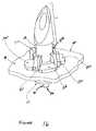
- FIG. 1is an exploded perspective view of a fluid delivery system incorporated into an animal cage assembly
- FIG. 2is an exploded perspective view of a fluid delivery system and diet delivery system in accordance with the present invention
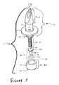
- FIG. 3is an exploded perspective view of an embodiment of a fluid delivery valve assembly in accordance with the present invention.
- FIG. 4is a side view of the fluid delivery valve assembly of FIG. 3 ;
- FIG. 5is a side cutaway view of the upper member of the fluid delivery valve assembly of FIG. 3 ;
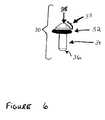
- FIG. 6is a perspective view of trigger assembly of a fluid delivery valve assembly in accordance with the present invention.
- FIG. 7is a top plain view of cup element in accordance with the present invention.
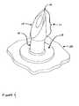
- FIG. 8is a perspective view of the cup element in accordance with the present invention.
- FIG. 9is a cutaway view of cup element in accordance with the present invention.
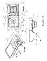
- FIG. 10is a perspective view of a diet delivery system
- FIG. 11is a top plan view of diet delivery system incorporating a fluid delivery system in accordance with the present invention.
- FIG. 12is a front cutaway view of diet delivery system
- FIG. 13is a bottom view of a fluid bag in accordance with the present invention.
- FIG. 14is a perspective view of a fluid bag and a fluid diet component with a fluid delivery system in accordance with the present invention.
- FIG. 15is a cutaway view of a fluid bag in accordance with the present invention.
- FIG. 16is a side perspective view of an upper member of a fluid delivery valve assembly including a support in accordance with the present invention.
- FIG. 17is a plain side view of a double-sided rack system incorporating an animal cage
- FIG. 18is an exploded perspective view of an embodiment of a fluid delivery valve assembly and diet delivery system in accordance with the present invention.
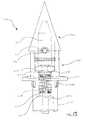
- FIG. 19is a side cutaway view of the fluid delivery valve assembly of FIG. 18 ;
- FIG. 20is a perspective view of the stem of the fluid delivery valve assembly of FIG. 18 ;
- FIG. 21is a side cutaway view of the fluid delivery valve assembly of FIG. 18 , showing the stem in the sealed position;
- FIG. 22is a side cutaway view of the fluid delivery valve assembly of FIG. 18 , showing the stem in the opened position;
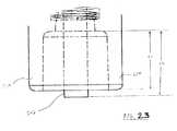
- FIG. 23is a side cutaway view of the fluid delivery valve assembly of FIG. 18 , showing the extension portion protecting the stem;
- FIG. 24is a side cutaway view of an upper member of a fluid delivery valve assembly including a wrapper in accordance with the present invention.
- FIG. 25is a side cutaway view of an upper member of a fluid delivery valve assembly including a disposable cap in accordance with the present invention.
- FIG. 26is a fluid bag filling and sealing device in accordance with the present invention.
- FIG. 27is a view of a fluid bag preparation room in accordance with the present invention.
- FIG. 28is another view of a fluid bag preparation room in accordance with the present invention.
- FIG. 29is another view of a fluid bag preparation room in accordance with the present invention.
- Cage assembly 90incorporates a filter retainer 91 , a filter frame 92 , a filter top lock 93 , a chew shield 94 , a plurality of snap rivets 95 , a fluid bag 60 containing fluid 70 , a fluid delivery valve assembly 1 , a diet delivery system 96 providing support member 50 , a chow receptacle 111 , a fluid bag receptacle 110 , and a cage body 98 .
- Cage body 98comprises a box-like animal cage with a combination diet delivery system 96 capable of providing both food and fluid to animals within cage assembly 90 .
- a filter 99is also generally provided with cage assembly 90 sandwiched between filter retainer 91 and filter frame 92 .
- Cage body 98is formed with integral side walls 100 , a bottom wall or floor 101 and an open top end. The open top of cage body 98 is bordered by peripheral lip 102 , which extends continuously there around.
- Cage body 98may also include a plurality of corner stacking tabs 103 for facilitating stacking and nesting of a plurality of cage bodies 98 .
- Fluid delivery valve assembly 1includes an upper member 10 , a spring element 20 , a trigger assembly 30 , and a cup element 40 for use in animal cage 90 .
- Water delivery system 1is held in place in animal cage 90 by support element 50 .
- Support element 50extends from diet delivery system 96 and forms a floor for fluid bag receptacle 110 .
- water delivery system 1may be molded into diet delivery system 96 .
- upper member 10includes piercing member 11 , core member 12 and flange member 13 .
- Upper member 10also defines fluid channel 14 .
- Arrow “A”defines the flow of fluid through fluid delivery valve assembly 1 to trigger assembly 30 where fluid flow can be actuated by an animal in animal cage 90 .
- Piercing member 11has a beveled tip 15 at its upper end, the upper edge of which presents a sharp piercing edge 16 that can come in contact and pierce fluid bag 60 , releasing fluid 70 in fluid bag 60 through fluid channel 14 .
- Flange member 13extends from core member 12 . In a preferred embodiment, flange member 13 is circular in dimension.
- flange member 13may be any shape desired, provided however, that at least a portion of flange member 13 is wider in diameter than fluid channel 14 of core member 12 .
- spring element 20may be a tightly wound coiled member which rests atop tip 35 of upper end 33 of stem 31 and enters upper member 10 through fluid channel 14 .
- fluid channel 14is dimensioned such that its upper extent within piercing member 11 is narrowed at position 17 such that it prevents spring element 20 from exiting fluid channel 14 through piercing member 11 .
- Trigger assembly 30includes a stem 31 , inserted through sealing member 32 .
- Stem 31having an upper end 33 and a lower end 36 .
- Lower end 36 of stem 31is substantially flat.
- Upper end 33 of stem 31is generally conical in shape, although other shapes may be used.
- Sealing member 32fits tightly around stem 31 thereby allowing limited movement around stem 31 .
- Sealing member 32is dimensioned such that the base of the conical portion of upper end 33 rests on it.
- Sealing member 32is formed of a resilient material, such as rubber, silicone rubber, or any other pliant malleable material. In a preferred embodiment, sealing member 32 is made of a material that is not deleterious to mammals.
- Cup element 40is depicted in FIGS. 7-9 .
- Cup element 40has a base 43 , an inner surface 41 , and an outer surface 42 .
- Base 43also defines actuation channel 400 .
- Lower end 36 of stem 31 of trigger assembly 30extends through actuation channel 400 towards the interior of animal cage 90 .
- Fluid channel 14extends from piercing edge 16 through piercing member 11 , core member 12 and spring element 20 . Fluid channel 14 terminates at the bottom wall of cup element 40 .
- Trigger assembly 30extends through actuation channel 400 .
- Cup element 40has friction fit with core member 12 of upper member 10 directly below flange member 13 .
- Diet delivery system 96which houses fluid bag receptacle 110 and chow receptacle 111 is shown in FIGS. 10-12 .
- fluid bag receptacle 110holds fluid bag 60 containing fluid 70 .
- Fluid delivery valve assembly 1is held securely in receptacle base 112 of fluid bag receptacle 110 by the interconnection between flange members 13 a , 13 b , 13 c and 13 d and locking members 51 a , 51 b , 51 c and 51 d .
- Piercing edge 16 of fluid delivery valve assembly 1punctures fluid bag 60 . As shown in FIGS.
- fluid bag receptacle 110may be molded 110 in order to facilitate the emptying of fluid 70 contained in fluid bag 60 by fluid delivery valve assembly 1 and to prevent the animal from gaining purchase on the fluid bag receptacle.
- fluid bag 60is tapered or dimensioned so as to facilitate the emptying of fluid bag 60 by fluid delivery valve assembly 1 .
- Fluid bag 60may be made replaceable or disposable and thus may be manufactured singly in any quantity according to the needs of a user.
- Fluid delivery valve assembly 1may be used to deliver the contents of fluid bag 60 to an animal in cage assembly 90 .
- Fluid 70 in fluid bag 60may include water, distilled water, water supplemented with various vitamins, minerals, medications such as antibiotics or anti-fungal agents, and/or other nutrients, or any fluid which is ingestible by a caged animal. Fluid 70 in fluid bag 60 is delivered to an animal in cage assembly 90 in a sterilized or sanitized condition so as to protect any animals in cage assembly 90 from contagion.
- Fluid bag 60may be formed in any desirable shape or volume. In a preferred embodiment, fluid bag 60 is formed to fit fluid bag receptacle 110 .
- fluid bag 60does not have to consist of a flexible material but that part thereof may be made of a rigid material.
- fluid bag 60would consist of one or more layers, which would tear upon insertion of piercing member 11 .
- flexible, stretchable, resilient plastic stickers 501may be provided which can be adhered to the bag to prevent tearing thereof and to form a seal about the inserted piercing member 11 .
- FIGS. 1-10depicted in FIGS.
- fluid bag 60could be made of a thinner plastic or inverted in the region where piercing edge 16 will penetrate fluid bag 60 , thereby allowing the end user to readily identify where fluid bag 60 should be punctured and helping fluid bag 60 nest within fluid bag receptacle 110 .
- fluid bag 60could be made of a resilient plastic or polymer material such that when piercing edge 16 penetrates fluid bag 60 at location 88 , fluid bag 60 adheres to piercing member 16 so as to stop fluid 70 from leaking out of fluid bag 60 .
- Fluid bag 60may be constructed out of any material which is capable of being punctured by piercing member 16 and which is capable of holding fluid in a sterilized condition.
- fluid bag 60is plastic or any other flexible material capable of containing a fluid to be delivered to one or more laboratory animals.
- fluid delivery valve assembly 1 , upper member 10 , fluid bag 60 and the contents thereof, fluid 70are capable of being sterilized by one or more of an assortment of different means including but not being limited to: ultraviolet light, irradiation, chemical treatment, reverse osmosis, gas sterilization, steam sterilization, filtration, autoclave, and/or distillation.
- Each of the elements of the current invention, fluid delivery valve assembly 1 , fluid bag 60 and fluid 70can be sterilized or sanitized alone or in combination with each other. Fluid 70 of fluid bag 60 may be sterilized either before or after fluid bag 60 is sealed.
- a chemical compound capable of sterilizing the fluid 70is put inside fluid bag 60 with fluid 70 prior to fluid bag 60 being sealed. Thereafter the compound sterilizes fluid 70 such that it can be delivered to an animal and consumed by that animal without harm. Other methods of sterilization are discussed below.
- leak preventing member 501is affixed or formed to upper member 10 and prevents a loss of fluid 70 from fluid bag 60 after puncture by piercing member 11 .
- piercing member 11may be rigidly fixed to support element 50 of fluid bag receptacle 110 (see FIGS. 1 and 4 ), in particular in the support for the bag having its point directed upwards so that piercing member 11 is automatically inserted into fluid bag 60 at location 88 when placing fluid bag 60 onto support element 50 or into fluid bag receptacle 110 ′.
- fluid bag 60is placed in fluid bag receptacle 110 of animal cage 90 .
- Fluid bag receptacle 110has a base 112 , an inner surface 114 and an outer surface 115 .
- Receptacle base 112also defines actuation channel 400 .
- stem 31 of trigger assembly 30extends through cup 40 towards the interior of animal cage 90 .
- that portion of receptacle base 112 which encircles actuation channel 400may include one or more locking members 51 .
- support member 50may have four (or some other number of) locking members 51 a , 51 b , 51 c and 51 d formed thereon which may be used to secure flange members 13 a , 13 b , 13 c and 13 d to support member 50 .
- flange members 13 a , 13 b , 13 c and 13 dmay vary in shape, provided however, that flange members 13 a , 13 b , 13 c and 13 d are secured in fluid receptacle base 112 or onto support member 50 by its locking members 51 a , 51 b , 51 c and 51 d .
- locking members 51 a , 51 b , 51 c and 51 dare shaped like fingers and flange member 13 is divided into four equal pieces, shown as flange members 13 a , 13 b (not shown), 13 c and 13 d.
- an animal isolation and caging rack system 600 of the inventionincludes an open rack 615 having a left side wall 625 and a right side wall 630 , a plurality of rack coupling stations 616 , a top 635 , and a bottom 640 .
- a plurality of posts 645are disposed in parallel between top 635 and bottom 640 .
- Vertical posts 645are preferably narrow and may comprise walls extending substantially from the front of rack 615 to the rear of rack 615 , or may each comprise two vertical members, one at or near the front of rack 615 and the other at or near the rear of rack 615 .
- Animal isolation and caging rack system 600also includes a plurality of air supply plena 610 and air exhaust plena 620 alternately disposed in parallel between left side wall 625 and right side wall 630 in rack 615 .
- the above discussed fluid delivery valve assembly 1while facilitating the providing of fluid to animals, was found to have some deficiencies when used in conjunction with certain rack and cage system configurations.
- the stem 31 of the trigger assembly 30when the stem 31 of the trigger assembly 30 is actuated by an animal, under certain circumstances, the stem may remain stuck in the open position even after the animal discontinues actuating the stem 31 . If the stem remains stuck in the open position, fluid may continue to leak into the cage and cage bedding, with the result being a waste of fluid, and the potential for the animal to become hypothermic, or otherwise adversely affected.
- stem 31due to the specific arrangement of the stem 31 , sealing member 32 and spring element 20 within the fluid channel 14 , when the stem 31 is actuated by an animal, the pivot point of upper end 33 of stem 31 about the bottom of spring element 20 tends not to be either predictable or consistent. Consequently, after actuation by an animal, stem 31 , in certain circumstances, will shift position in relation to spring element 20 , thus not allowing spring element 20 to bias stem 31 back into the desired closed position.
- FIG. 18there is shown a fluid delivery valve assembly 200 that overcomes the above-discussed deficiency because, among other modifications, the arrangement of stem member 240 , spring member 250 , and sealing member 260 is different than that of their respective corresponding parts in fluid delivery valve assembly 1 .
- This arrangement of stem member 240 , spring member 250 , and sealing member 260discussed in detail below, provides for a predictable and consistent pivot point for stem member 240 , thus facilitating a more consistent return to the closed position in the absence of actuation by an animal.
- fluid delivery valve assembly 200is different in structure and arrangement to that of fluid delivery valve assembly 1 in several respects.
- fluid delivery valve assembly 200may be used in all embodiments discussed above with reference to fluid delivery valve assembly 1 .
- fluid delivery valve assembly 200may be used as well, in accordance with the invention.
- Fluid delivery valve assembly 200having an upper member 210 , and a base 220 .
- Fluid delivery valve assembly 200also includes sealing member 260 , stem member 240 , and spring member 250 .
- Upper member 210is formed with generally conical piercing member 211 having sharp point 214 for piercing fluid bag 60 as described above.
- One or more fluid apertures 215are defined in a portion of piercing member 210 , to facilitate the flow of fluid 70 from bag 60 into a fluid channel 216 defined within the piercing member 210 .
- Upper member 210is also formed with connecting member 212 , having gripping portion 213 encircling a portion thereof.
- Base 220being generally cylindrical in shape, includes top portion 221 and bottom portion 222 , which are separated by flange member 226 which encircles base 220 and extends outwardly therefrom.
- Flange member 226(having a top surface 227 and a bottom surface 228 ) may be used to facilitate mounting or positioning of fluid delivery valve assembly 200 as is described above with regard to fluid delivery valve assembly 1 .
- Top portion 221may have an inner surface 223 with gripping portion 213 disposed thereon.
- Upper member 210is designed and dimensioned to be coupled to base 220 with connecting member 212 being inserted into base top portion 221 .
- the couplingmay be facilitated by the frictional interaction of gripping portion 213 of upper member 210 with gripping portion 224 of base 220 .
- Sealing member 260 , stem member 240 , and spring member 250are disposed within base fluid channel 230 .
- Stem member 240has a top portion 241 that may be generally flat, such that flow aperture 265 of sealing member 260 may be advantageously sealed when a portion of bottom surface 262 of sealing member 260 is contacted by top surface 243 of stem member 240 .
- Actuation portion 242 of stem member 240extends through spring member 250 and through base fluid channel 230 .
- Spring member 250serves to bias stem member 240 against sealing member 260 to facilitate control of the flow of fluid, as described above with respect to fluid delivery valve assembly 1 .
- spring member 250is retained within base fluid channel 230 at its bottom end as fluid channel 230 has narrow portion 232 , which serves to block spring member 250 from passing through and out of fluid channel 230 .
- the top of spring member 250abuts the lower surface 244 (see FIG. 20 ) of stem member 240 .
- Spring member 250serves to bias stem member 240 in a vertical orientation, thus forming a seal between top surface 243 and sealing member 260 . This seal may be facilitated by the use of lower ridge 266 to concentrate the biasing force of spring member 250 to form a seal against stem member 240 .
- FIGS. 21 and 22there is shown the operation of fluid delivery valve assembly 200 when stem member 240 is actuated by an animal. It should be noted that spring member 250 is not shown in FIGS. 23 and 24 for sake of clarity. During actuation of stem member 240 by an animal, however, as discussed above, spring member 250 provides a biasing force to bias stem member 240 toward a generally vertical position.
- stem member 240is positioned generally vertically, with top surface 243 of stem member 240 advantageously abutting lower ridge 266 of sealing member 260 at sealing point 246 .
- the use of lower ridge 266 in conjunction with top surface 240advantageously serves to focus and concentrate the biasing force of spring member 250 to form a seal as discussed above.
- Fluid delivery system 200is shown having been punctured into fluid bag 60 such that fluid 70 may flow from fluid bag 60 into fluid aperture 215 of upper member 210 , and in turn flow into fluid channel 216 , through flow aperture 265 of sealing member 260 , down to sealing point 246 .
- stem member 240in the vertical (sealed) position, flow of the fluid is stopped.
- bag 60once punctured by fluid delivery valve assembly 200 , should have its outer wall positioned in the range along surface 235 of top portion 201 of base 220 such that it remains disposed in the portion delimited at its upper bounds by bag retention wall 217 and at its lower bounds by flange top surface 227 .
- flow aperture 215 and (in some embodiments) aperture portion 218may be advantageously positioned about an edge of bag retention wall 217 .
- stem member 240positioned as it would be while an animal actuates actuation portion 242 of stem member 240 in a direction B.
- stem member 240pivots about pivot point 236 such that top surface 243 of stem member 240 moves away from the lower ridge 266 of sealing member 260 . This movement allows fluid 70 at flow aperture 265 of sealing member 250 to flow down through gap 237 , into fluid channel 230 , and out to the animal in the general direction A.
- Base 220may be formed with abutment wall 233 disposed in fluid channel 230 such that the maximum travel of stem member 240 is limited such that the flow of fluid 70 is advantageously limited to a desired value. Additionally, stem member 240 , base 220 , sealing member 250 and spring member 250 may be advantageously designed and dimensioned such that stem member 240 pivots at a consistent and predictable pivot point 236 and will thus not be subject to sticking or jamming in the open position after stem member 240 is released from actuation by the animal. Consequently, the wasting of fluid and the exposure of animals to hypothermia or other problems caused by excessive wetting of the cage and bedding material may be minimized.
- embodiments of the inventionmay be formed with base 220 of fluid delivery valve assembly 200 having extension portion 234 .
- Extension portion 234may serve, in certain application specific scenarios, to protect the actuation portion 242 of stem member 240 from being accidentally bumped by an animal, as only a portion of actuation portion 242 extends beyond extension portion 234 .
- the relative lengths L1 and L2 of extension portion 234 and actuation portion 242may be adjusted based on the results desired, and the types of animals being fed, as well as other factors.
- water delivery system 1(or fluid delivery valve assembly 200 ) is sterilized and/or autoclaved and maintained in a sterilized state prior to use in a wrapper 47 or other suitable container so as to avoid infecting an animal in animal cage 90 (while, for sake of brevity, the embodiments of the invention discussed below make specific reference only to fluid delivery valve assembly 1 , it is to be understood that fluid delivery valve assembly 200 may also be used in all instances as well).
- fluid delivery valve assembly 1When a user determines that a clean water delivery system is needed in conjunction with a fluid bag 60 , water delivery system 1 is removed from wrapper 47 in sterile conditions or utilizing non-contaminating methods and inserted into animal cage 90 in fluid bag receptacle 110 (while it is contemplated that all of fluid delivery valve assembly 1 would be contained within wrapper 47 , only a portion of fluid delivery valve assembly 1 is illustrated in FIG. 24 ). Thereafter fluid bag 60 is placed in fluid bag receptacle 110 and is punctured by piercing member 11 such that fluid 70 (i.e., water) is released through fluid channel 14 to an animal in animal cage 90 . This procedure insures that sterilized fluid 70 is delivered through an uncontaminated fluid channel and that fluid delivery valve assembly 1 is itself uncontaminated and pathogen free. Additionally, in an embodiment of the invention, fluid delivery valve assembly 1 may be sold and stored in blister packs in groups of various quantities.
- the upper portion of fluid delivery valve assembly 1is covered with a disposable cap 45 , that can be removed when a user wants to use water delivery system 1 to pierce fluid bag 60 and place it in fluid bag receptacle 110 for delivery of a fluid to an animal in animal cage 90 .
- Disposable cap 45can be made from any suitable material and may be clear, color-coded to indicate the type of fluid in fluid bag 60 , clear or opaque. Disposable cap 45 is easily removed from fluid delivery valve assembly 1 . While cap 45 would not provide for a sterilized fluid delivery valve assembly 1 , it would provide a labeling function, as well as, in an embodiment, provide protection from inadvertent stabbing of a user.
- An embodiment of the present inventionprovides a system and method for fluid delivery to one or more animal cages.
- the system providedhas at least two methods of use, one which includes providing sealed sanitized bags of fluid for use in an animal cage or caging system.
- the providerprovides the pre-packaged and uncontaminated fluid (e.g., water, or fluid with nutrients etc., as needed by an animal) for use preferably by delivering sanitized, fluid-filled, bags to a site designated by a user.
- the providermay locate a sealing apparatus, material for making the fluid bags and fluid supply at a location designated by the user. Thereafter, the provider will assemble, fill and seal the appropriate number of fluid bags for a user at the designated location.
- the providerprovides a sealing apparatus and the material for making the fluid bags to a user.
- the providermay also supply any appropriate fluid to the user at a location designated by the user. The user thereafter assembles, fills and seals the fluid bags for use in the fluid delivery system of the invention as appropriate.
- FIG. 26A fluid bag filling and sealing method and system 300 , in accordance with an embodiment of the invention, is illustrated in FIG. 26 .
- Bag material 310which may be formed of any suitable material as described above, is stored in bulk form, such as, for example, in roll form.
- bag material 310is moved over bag forming portion 330 such that the generally flat shape of bag material 310 is formed into a tube.
- a vertical seal device 340forms a vertical seal in bag material 310 , thus completing the formation of a tube.
- Contents supply portion 320serves to add ingredients, via, for example, gravity feed, into the tube of bag material 310 .
- Contents supply portion 320may include liquid and powder storage containers, and various pumps and other supply means, such that, for example, fluid 70 , either with or without any additives as discussed above, may be added and metered out in appropriate quantities as is known in the art. Additionally, contents supply portion 320 may include heating and/or sterilizing equipment such that the contents supplied from contents supply portion 320 are in a generally sterilized condition.
- horizontal seal device 350forms a horizontal seal, either thermally, by adhesives, or by some other art recognized method as would be known to one skilled in the art.
- the horizontal sealserves to isolate the contents of the tube into separate portions.
- the bag cutting devicecuts the bag material at the horizontal seal to form individual fluid bags 60 containing fluid 70 .
- the exact steps taken to form the fluid bags 60may be varied as a matter of application specific design choice. In some embodiments of the invention. steps may be added, left out, or performed in a different order. Additionally, the contents and bag material 310 of fluid bags 60 may be sterilized either before or after the completed bags are formed.
- the fluid 70is heated to approximately 180° F., and the fluid bags are stacked in storage containers 370 with the result that the fluid 70 , fluid bags 60 and storage containers all become sterilized to a satisfactory degree.
- a cage body 98may be used as such a storage container. Additional parts of this process may also be automated, as is shown by the use of robotic arm 380 in stacking containers.
- Storage containers 370may also be supplied with fluid bags 60 at a workstation 382 , before placement in a isolation and caging rack system 600 . Additionally, storage containers 370 (or cage bodies 98 ) may be passed through various other sterilizing devices.
Landscapes
- Life Sciences & Earth Sciences (AREA)
- Environmental Sciences (AREA)
- Animal Husbandry (AREA)
- Biodiversity & Conservation Biology (AREA)
- Zoology (AREA)
- Health & Medical Sciences (AREA)
- Animal Behavior & Ethology (AREA)
- Clinical Laboratory Science (AREA)
- General Health & Medical Sciences (AREA)
- Birds (AREA)
- Feeding And Watering For Cattle Raising And Animal Husbandry (AREA)
- Housing For Livestock And Birds (AREA)
- Infusion, Injection, And Reservoir Apparatuses (AREA)
- Packages (AREA)
Abstract
Description
Claims (22)
Priority Applications (10)
| Application Number | Priority Date | Filing Date | Title |
|---|---|---|---|
| US10/274,619US6941893B2 (en) | 2001-10-19 | 2002-10-21 | Fluid delivery system |
| US10/824,224US6986324B2 (en) | 2001-10-19 | 2004-04-13 | Fluid delivery valve system and method |
| US10/823,868US6983721B2 (en) | 2001-10-19 | 2004-04-13 | Method and system of providing sealed bags of fluid at the clean side of a laboratory facility |
| US10/962,940US7222586B2 (en) | 2001-10-19 | 2004-10-12 | Fluid delivery adapter |
| US11/267,472US7303713B2 (en) | 2001-10-19 | 2005-11-04 | Fluid delivery valve system and method |
| US11/854,043US7937836B2 (en) | 2001-10-19 | 2007-09-12 | Fluid delivery valve system and method of assembling |
| US11/871,916US7546816B2 (en) | 2001-10-19 | 2007-10-12 | Fluid delivery valve adapter |
| US12/973,310US8291865B2 (en) | 2001-10-19 | 2010-12-20 | Method and system of providing sealed bags of fluid at the clean side of a laboratory facility |
| US13/656,278US9763425B2 (en) | 2001-10-19 | 2012-10-19 | Method and system of providing sealed bags of fluid at the clean side of a laboratory facility |
| US14/149,375US20140158058A1 (en) | 2001-10-19 | 2014-01-07 | Fluid delivery system |
Applications Claiming Priority (2)
| Application Number | Priority Date | Filing Date | Title |
|---|---|---|---|
| US34621801P | 2001-10-19 | 2001-10-19 | |
| US10/274,619US6941893B2 (en) | 2001-10-19 | 2002-10-21 | Fluid delivery system |
Related Child Applications (5)
| Application Number | Title | Priority Date | Filing Date |
|---|---|---|---|
| US10/824,224Continuation-In-PartUS6986324B2 (en) | 2001-10-19 | 2004-04-13 | Fluid delivery valve system and method |
| US10/823,868Continuation-In-PartUS6983721B2 (en) | 2001-10-19 | 2004-04-13 | Method and system of providing sealed bags of fluid at the clean side of a laboratory facility |
| US10/962,940Continuation-In-PartUS7222586B2 (en) | 2001-10-19 | 2004-10-12 | Fluid delivery adapter |
| US10/588,430Continuation-In-PartUS7866280B2 (en) | 2004-04-13 | 2005-04-11 | Method and system of providing sealed bags of fluid at the clean side of a laboratory facility |
| US58843007AContinuation-In-Part | 2001-10-19 | 2007-09-11 |
Publications (2)
| Publication Number | Publication Date |
|---|---|
| US20030226515A1 US20030226515A1 (en) | 2003-12-11 |
| US6941893B2true US6941893B2 (en) | 2005-09-13 |
Family
ID=23358443
Family Applications (1)
| Application Number | Title | Priority Date | Filing Date |
|---|---|---|---|
| US10/274,619Expired - LifetimeUS6941893B2 (en) | 2001-10-19 | 2002-10-21 | Fluid delivery system |
Country Status (9)
| Country | Link |
|---|---|
| US (1) | US6941893B2 (en) |
| EP (2) | EP1513395B1 (en) |
| JP (1) | JP4236580B2 (en) |
| CN (1) | CN100521926C (en) |
| AU (1) | AU2002362934B2 (en) |
| CA (2) | CA2625469C (en) |
| IL (2) | IL161494A0 (en) |
| MX (1) | MXPA04003682A (en) |
| WO (1) | WO2003033396A2 (en) |
Cited By (8)
| Publication number | Priority date | Publication date | Assignee | Title |
|---|---|---|---|---|
| WO2005099446A3 (en)* | 2004-04-13 | 2006-03-16 | Hydropac Lab Products Inc | Fluid delivery valve system and method |
| US20070245969A1 (en)* | 2006-04-24 | 2007-10-25 | Edstrom Industries, Inc. | Animal Watering Valve Having Elastomeric Diaphragm |
| USD617057S1 (en)* | 2009-02-12 | 2010-06-01 | West Agro Inc. | Animal feeding nipple |
| USD617508S1 (en)* | 2009-02-12 | 2010-06-08 | West Agro Inc. | Animal feeding nipple |
| US20110023789A1 (en)* | 2007-12-10 | 2011-02-03 | The Cooper Union For The Advancement Of Science And Art | Gas delivery system for an animal storage container |
| US20120267396A1 (en)* | 2011-04-22 | 2012-10-25 | Quinlan Jr Robert L | Foam dispenser having selectively pressurized container |
| US20140001279A1 (en)* | 2012-06-29 | 2014-01-02 | Acorn Engineering Company | Auto stop fluid valve |
| US11603948B2 (en) | 2018-06-18 | 2023-03-14 | Avidity Science, Llc | Animal watering valve |
Families Citing this family (15)
| Publication number | Priority date | Publication date | Assignee | Title |
|---|---|---|---|---|
| US6983721B2 (en)* | 2001-10-19 | 2006-01-10 | Hydropac/Lab Products, Inc. | Method and system of providing sealed bags of fluid at the clean side of a laboratory facility |
| US9763425B2 (en) | 2001-10-19 | 2017-09-19 | Hydropac/Lab Products, Inc. | Method and system of providing sealed bags of fluid at the clean side of a laboratory facility |
| US7546816B2 (en)* | 2001-10-19 | 2009-06-16 | Lab Products, Inc. | Fluid delivery valve adapter |
| EP1513395B1 (en) | 2001-10-19 | 2018-12-05 | Hydropac/lab Products, Inc. | Fluid delivery system |
| GB0225841D0 (en) | 2002-11-06 | 2002-12-11 | Aquaflow Lab Products Ltd | Valve arrangement and assembly for dispensing a liquid from a container to an animal |
| US7513218B1 (en) | 2004-09-14 | 2009-04-07 | Edstrom Industries, Inc. | Potable water delivery system for animals |
| US20070154119A1 (en)* | 2005-12-29 | 2007-07-05 | Macler Henry Ii | Fluid-filled bag and overwrap assembly |
| AU2013267069B2 (en)* | 2005-12-29 | 2016-07-07 | Neverfail Springwater Limited | Fluid-filled bag and overwrap assembly |
| US9732882B2 (en)* | 2013-03-15 | 2017-08-15 | Hydropac/Lab Products, Inc. | Fluid delivery valve system and method |
| CN104686383A (en)* | 2013-12-05 | 2015-06-10 | 深圳市泓腾生物科技有限公司 | A cage box capable of replacing bedding materials independently |
| CN108719253A (en)* | 2018-06-03 | 2018-11-02 | 安徽丰硕种业有限公司 | A kind of wheat planting prevention and control of plant diseases, pest control drug flusher |
| IT201800006587A1 (en)* | 2018-06-22 | 2019-12-22 | LIQUID DISPENSING DEVICE, IN PARTICULAR FOR DRINKING ANIMALS | |
| CN109392761A (en)* | 2018-10-24 | 2019-03-01 | 曲静 | A kind of multi-functional livestock farms and cultural method |
| CN114727589A (en)* | 2019-11-15 | 2022-07-08 | 斯派克初姆布兰斯有限公司 | Aquarium feeder with food pod system and method |
| CN112977570B (en)* | 2021-02-04 | 2022-12-16 | 台州玖枫科技有限公司 | Sesame oil extract rapid transfer device using sesame oil as baby skin care product |
Citations (67)
| Publication number | Priority date | Publication date | Assignee | Title |
|---|---|---|---|---|
| US1059231A (en)* | 1912-09-24 | 1913-04-15 | Frederick James Storey | Tap, cock, and the like, having tapping means. |
| US2001481A (en) | 1934-07-16 | 1935-05-14 | Crane Packing Co | Dispensing attachment for cans |
| US2192479A (en) | 1938-08-04 | 1940-03-05 | Jr John P Nissen | Implement for applying fluid and semipaste materials |
| US2239104A (en) | 1938-02-07 | 1941-04-22 | Emil A Kern | Combined fire shutter and observation window for motion picture projection booths |
| US2333068A (en) | 1942-12-19 | 1943-10-26 | Zwanzig William | Soap dispenser |
| US2552155A (en)* | 1948-08-31 | 1951-05-08 | John A Danielson | Liquid-dispensing valve spile |
| US2785881A (en)* | 1954-07-26 | 1957-03-19 | Dolan Arthur | Faucet attachment |
| US2805794A (en) | 1953-11-24 | 1957-09-10 | Amon Robert | Dispensing devices for liquid or paste material |
| US2936098A (en)* | 1957-10-18 | 1960-05-10 | Narbo Lauritz Martin | Combined faucet and valve |
| US3100586A (en)* | 1960-03-14 | 1963-08-13 | John R Haynes | Valved opener for sealed containers |
| US3482258A (en) | 1968-07-23 | 1969-12-02 | Esterline Corp | Sterile ink supply |
| US3539076A (en) | 1969-04-02 | 1970-11-10 | Peggy Weiss | Valved liquid dispenser |
| US3645234A (en) | 1970-09-21 | 1972-02-29 | Schroer Mfg Co Inc | Animal feeding device |
| US3791590A (en) | 1972-09-27 | 1974-02-12 | Jones & Co Inc R A | Drip inhibiting glue nozzle |
| US3874343A (en)* | 1973-03-03 | 1975-04-01 | Motohiro Niki | Water dispenser for small animals |
| US3958535A (en) | 1974-10-24 | 1976-05-25 | Matthew Salvia | Universal animal feed bag |
| US4006716A (en)* | 1975-12-01 | 1977-02-08 | Atco Manufacturing Co., Inc. | Miniature animal-watering valve |
| US4022159A (en) | 1974-10-24 | 1977-05-10 | Matthew Salvia | Shipping cage for feeding animals water from disposable bags |
| US4040389A (en) | 1975-09-12 | 1977-08-09 | Walters James H | Animal feeding device |
| US4120420A (en) | 1978-02-16 | 1978-10-17 | The Procter & Gamble Company | Lined parallelepipedal package for dispensing flowable materials |
| US4130088A (en) | 1975-11-17 | 1978-12-19 | Matthew Salvia | Shipping cage for feeding animals water from disposable bags |
| US4318497A (en) | 1980-06-23 | 1982-03-09 | Nalco Chemical Company | Corrugated shipping container for viscous refractory slurries and discharge apparatus therefor |
| US4329941A (en)* | 1981-01-30 | 1982-05-18 | Motohiro Niki | Water dispenser for small animals |
| US4341328A (en) | 1980-01-30 | 1982-07-27 | Redick Jr Richard W | Adapter for bottled water dispenser |
| US4346672A (en)* | 1981-01-30 | 1982-08-31 | Motohiro Niki | Water dispenser for small animals |
| US4370948A (en)* | 1980-03-31 | 1983-02-01 | Atkins Robert C | Nipple waterer |
| US4391225A (en)* | 1982-02-18 | 1983-07-05 | Sparks Jacob D | Springless nipple waterer valve |
| US4402343A (en)* | 1979-01-12 | 1983-09-06 | Earl Clayton Thompson | Animal watering valve with protected biasing spring |
| US4406253A (en)* | 1981-11-16 | 1983-09-27 | Atco Manufacturing Co. Inc. | Animal bite valve |
| US4421253A (en) | 1982-02-17 | 1983-12-20 | Willamette Industries, Inc. | Disposable container assembly for liquids or semi-liquids in bulk |
| US4633816A (en)* | 1983-05-24 | 1987-01-06 | Ove Olsson and Ingegard Olsson | Device for controlled discharge of liquid to animals |
| US4697414A (en) | 1985-12-09 | 1987-10-06 | The Garrett Corporation | Lubrication apparatus |
| US4723687A (en) | 1981-03-16 | 1988-02-09 | Franz Kutterer | Tube with screw cap |
| US4819585A (en)* | 1987-01-16 | 1989-04-11 | Roger Dolan | Freeze resistant adjustable flow rate animal nipple waterer |
| US4896629A (en)* | 1988-08-30 | 1990-01-30 | Aqua Drop Corporation | Poultry watering valve |
| US5002202A (en) | 1988-09-07 | 1991-03-26 | Karpisek Ladislav Stephan | Bag puncturing means |
| US5065700A (en)* | 1990-10-17 | 1991-11-19 | Se Lab Group, Inc. | Shutter for animal-watering valve |
| US5127550A (en) | 1989-08-07 | 1992-07-07 | Minnesota Mining And Manufacturing Company | Device for dispensing flowable material from a flexible bag |
| US5131622A (en)* | 1990-12-03 | 1992-07-21 | Chang Shih Chih | Metering valve for water faucet |
| US5303751A (en) | 1991-10-04 | 1994-04-19 | Fresenius Ag | Spiked bag packaging system |
| US5307953A (en) | 1991-12-03 | 1994-05-03 | Glaxo Group Limited | Single dose dispenser having a piercing member |
| US5325995A (en)* | 1989-07-27 | 1994-07-05 | Du Pont Canada Inc. | Piercing nozzle for pouch fitment |
| US5429273A (en) | 1990-05-02 | 1995-07-04 | Du Pont Canada Inc. | Apparatus for dispensing flowable materials from a pouch |
| US5462200A (en) | 1994-01-21 | 1995-10-31 | Automatic Liquid Packaging, Inc. | Threaded cap with controlled orifice liner for piercing a sealed container |
| US5645913A (en)* | 1995-03-02 | 1997-07-08 | W. R. Grace & Co.-Conn. | Film and pouch with patch of high elongation |
| US5791519A (en) | 1995-12-27 | 1998-08-11 | International Sanitary Ware Manufacturing Cy, S.A. | Soap bag |
| US5816194A (en)* | 1997-08-25 | 1998-10-06 | Novalek, Inc. | Animal operated water dispensing valve |
| US5823144A (en) | 1996-02-14 | 1998-10-20 | Edstrom Industries, Inc. | Cage and rack system incorporating automatic water docking system, latch mechanism, and quick-connect coupling |
| US5855298A (en)* | 1994-08-18 | 1999-01-05 | Creamiser Products Corporation | Tapping stem for liquid supply container |
| US5855223A (en)* | 1994-06-14 | 1999-01-05 | Tuomo Halonen Oy | Emptying valve for emptying sealed liquid packages such as liquid pouches |
| US5884810A (en)* | 1994-06-29 | 1999-03-23 | Vizcarra; Carlos Bartning Rodriguez | Dispenser having a breakable and replaceable membrane for a rigid container for liquids |
| US5895383A (en) | 1996-11-08 | 1999-04-20 | Bracco Diagnostics Inc. | Medicament container closure with recessed integral spike access means |
| US5971207A (en) | 1997-05-16 | 1999-10-26 | Pcf Group, Inc. | Nozzle apparatus and method for dispensing powder coating material |
| US5975359A (en) | 1995-12-27 | 1999-11-02 | International Sanitary Ware Manufacturing Cy, S.A. | Needle engaging soap bag |
| US6003468A (en)* | 1998-07-10 | 1999-12-21 | Edstrom Industries, Inc. | Animal watering valve with deflectable elastomeric boot |
| US6058881A (en)* | 1996-11-12 | 2000-05-09 | Thompson; Earl C. | Demand watering valve for fowl, birds and small animals |
| US6082583A (en) | 1997-04-04 | 2000-07-04 | Belmont Housing Corporation | Device and method for providing liquid to a user's mouth |
| US6095433A (en)* | 1997-08-28 | 2000-08-01 | Langdon (London) Limited | Irrigation system and method of performing same |
| US6098844A (en) | 1998-01-23 | 2000-08-08 | Kenneth Nicolle | Water dispensing system |
| US6206242B1 (en) | 1996-10-10 | 2001-03-27 | Henkel Kommanditgesellschaft Auf Aktien | Pot with a flexible storage barrel and follow-up plate |
| US6210361B1 (en) | 1997-08-22 | 2001-04-03 | Deka Products Limited Partnership | System for delivering intravenous drugs |
| US6223940B1 (en)* | 1998-11-09 | 2001-05-01 | Radius International Limited Partnership | Fluid storage container and dispenser, and method of dispensing |
| US6247616B1 (en) | 1995-06-07 | 2001-06-19 | Automatic Liquid Packaging, Inc. | Cap with draining spike and flip top for use with hermetically sealed dispensing container |
| US6257171B1 (en) | 1998-01-16 | 2001-07-10 | Animal Care Systems, Inc. | Animal caging and biological storage systems |
| US6339998B1 (en)* | 1999-11-22 | 2002-01-22 | Motohiro Niki, et al. | Water feed device for small animal rearing apparatus |
| US6488045B1 (en)* | 2000-04-18 | 2002-12-03 | Edstrom Industries, Inc. | Water supply manifold and method for its production |
| US20030226515A1 (en) | 2001-10-19 | 2003-12-11 | Gabriel George S. | Fluid delivery system |
Family Cites Families (2)
| Publication number | Priority date | Publication date | Assignee | Title |
|---|---|---|---|---|
| US3228377A (en)* | 1963-08-14 | 1966-01-11 | Grassano Vincent | Automatic watering system for animals |
| US3762606A (en)* | 1971-08-11 | 1973-10-02 | O Lande | Containerized liquid dispensing system |
- 2002
- 2002-10-21EPEP02801795.2Apatent/EP1513395B1/ennot_activeExpired - Lifetime
- 2002-10-21AUAU2002362934Apatent/AU2002362934B2/ennot_activeExpired
- 2002-10-21USUS10/274,619patent/US6941893B2/ennot_activeExpired - Lifetime
- 2002-10-21EPEP08009683Apatent/EP1958501A3/ennot_activeWithdrawn
- 2002-10-21WOPCT/US2002/033543patent/WO2003033396A2/enactiveSearch and Examination
- 2002-10-21CACA2625469Apatent/CA2625469C/ennot_activeExpired - Lifetime
- 2002-10-21CNCNB028256050Apatent/CN100521926C/ennot_activeExpired - Lifetime
- 2002-10-21CACA002464127Apatent/CA2464127C/ennot_activeExpired - Lifetime
- 2002-10-21JPJP2003536145Apatent/JP4236580B2/ennot_activeExpired - Lifetime
- 2002-10-21MXMXPA04003682Apatent/MXPA04003682A/enactiveIP Right Grant
- 2002-10-21ILIL16149402Apatent/IL161494A0/enactiveIP Right Grant
- 2004
- 2004-04-19ILIL161494Apatent/IL161494A/enunknown
Patent Citations (69)
| Publication number | Priority date | Publication date | Assignee | Title |
|---|---|---|---|---|
| US1059231A (en)* | 1912-09-24 | 1913-04-15 | Frederick James Storey | Tap, cock, and the like, having tapping means. |
| US2001481A (en) | 1934-07-16 | 1935-05-14 | Crane Packing Co | Dispensing attachment for cans |
| US2239104A (en) | 1938-02-07 | 1941-04-22 | Emil A Kern | Combined fire shutter and observation window for motion picture projection booths |
| US2192479A (en) | 1938-08-04 | 1940-03-05 | Jr John P Nissen | Implement for applying fluid and semipaste materials |
| US2333068A (en) | 1942-12-19 | 1943-10-26 | Zwanzig William | Soap dispenser |
| US2552155A (en)* | 1948-08-31 | 1951-05-08 | John A Danielson | Liquid-dispensing valve spile |
| US2805794A (en) | 1953-11-24 | 1957-09-10 | Amon Robert | Dispensing devices for liquid or paste material |
| US2785881A (en)* | 1954-07-26 | 1957-03-19 | Dolan Arthur | Faucet attachment |
| US2936098A (en)* | 1957-10-18 | 1960-05-10 | Narbo Lauritz Martin | Combined faucet and valve |
| US3100586A (en)* | 1960-03-14 | 1963-08-13 | John R Haynes | Valved opener for sealed containers |
| US3482258A (en) | 1968-07-23 | 1969-12-02 | Esterline Corp | Sterile ink supply |
| US3539076A (en) | 1969-04-02 | 1970-11-10 | Peggy Weiss | Valved liquid dispenser |
| US3645234A (en) | 1970-09-21 | 1972-02-29 | Schroer Mfg Co Inc | Animal feeding device |
| US3791590A (en) | 1972-09-27 | 1974-02-12 | Jones & Co Inc R A | Drip inhibiting glue nozzle |
| US3874343A (en)* | 1973-03-03 | 1975-04-01 | Motohiro Niki | Water dispenser for small animals |
| US3958535A (en) | 1974-10-24 | 1976-05-25 | Matthew Salvia | Universal animal feed bag |
| US4022159A (en) | 1974-10-24 | 1977-05-10 | Matthew Salvia | Shipping cage for feeding animals water from disposable bags |
| US4040389A (en) | 1975-09-12 | 1977-08-09 | Walters James H | Animal feeding device |
| US4130088A (en) | 1975-11-17 | 1978-12-19 | Matthew Salvia | Shipping cage for feeding animals water from disposable bags |
| US4006716A (en)* | 1975-12-01 | 1977-02-08 | Atco Manufacturing Co., Inc. | Miniature animal-watering valve |
| US4120420A (en) | 1978-02-16 | 1978-10-17 | The Procter & Gamble Company | Lined parallelepipedal package for dispensing flowable materials |
| US4402343A (en)* | 1979-01-12 | 1983-09-06 | Earl Clayton Thompson | Animal watering valve with protected biasing spring |
| US4341328A (en) | 1980-01-30 | 1982-07-27 | Redick Jr Richard W | Adapter for bottled water dispenser |
| US4370948A (en)* | 1980-03-31 | 1983-02-01 | Atkins Robert C | Nipple waterer |
| US4318497A (en) | 1980-06-23 | 1982-03-09 | Nalco Chemical Company | Corrugated shipping container for viscous refractory slurries and discharge apparatus therefor |
| US4329941A (en)* | 1981-01-30 | 1982-05-18 | Motohiro Niki | Water dispenser for small animals |
| US4346672A (en)* | 1981-01-30 | 1982-08-31 | Motohiro Niki | Water dispenser for small animals |
| US4723687A (en) | 1981-03-16 | 1988-02-09 | Franz Kutterer | Tube with screw cap |
| US4406253A (en)* | 1981-11-16 | 1983-09-27 | Atco Manufacturing Co. Inc. | Animal bite valve |
| US4421253A (en) | 1982-02-17 | 1983-12-20 | Willamette Industries, Inc. | Disposable container assembly for liquids or semi-liquids in bulk |
| US4391225A (en)* | 1982-02-18 | 1983-07-05 | Sparks Jacob D | Springless nipple waterer valve |
| US4633816A (en)* | 1983-05-24 | 1987-01-06 | Ove Olsson and Ingegard Olsson | Device for controlled discharge of liquid to animals |
| US4697414A (en) | 1985-12-09 | 1987-10-06 | The Garrett Corporation | Lubrication apparatus |
| US4819585A (en)* | 1987-01-16 | 1989-04-11 | Roger Dolan | Freeze resistant adjustable flow rate animal nipple waterer |
| US4896629A (en)* | 1988-08-30 | 1990-01-30 | Aqua Drop Corporation | Poultry watering valve |
| US5002202A (en) | 1988-09-07 | 1991-03-26 | Karpisek Ladislav Stephan | Bag puncturing means |
| US5325995A (en)* | 1989-07-27 | 1994-07-05 | Du Pont Canada Inc. | Piercing nozzle for pouch fitment |
| US5127550A (en) | 1989-08-07 | 1992-07-07 | Minnesota Mining And Manufacturing Company | Device for dispensing flowable material from a flexible bag |
| US5429273A (en) | 1990-05-02 | 1995-07-04 | Du Pont Canada Inc. | Apparatus for dispensing flowable materials from a pouch |
| US5065700A (en)* | 1990-10-17 | 1991-11-19 | Se Lab Group, Inc. | Shutter for animal-watering valve |
| US5131622A (en)* | 1990-12-03 | 1992-07-21 | Chang Shih Chih | Metering valve for water faucet |
| US5303751A (en) | 1991-10-04 | 1994-04-19 | Fresenius Ag | Spiked bag packaging system |
| US5307953A (en) | 1991-12-03 | 1994-05-03 | Glaxo Group Limited | Single dose dispenser having a piercing member |
| US5462200A (en) | 1994-01-21 | 1995-10-31 | Automatic Liquid Packaging, Inc. | Threaded cap with controlled orifice liner for piercing a sealed container |
| US5855223A (en)* | 1994-06-14 | 1999-01-05 | Tuomo Halonen Oy | Emptying valve for emptying sealed liquid packages such as liquid pouches |
| US5884810A (en)* | 1994-06-29 | 1999-03-23 | Vizcarra; Carlos Bartning Rodriguez | Dispenser having a breakable and replaceable membrane for a rigid container for liquids |
| US5855298A (en)* | 1994-08-18 | 1999-01-05 | Creamiser Products Corporation | Tapping stem for liquid supply container |
| US6026988A (en)* | 1994-08-18 | 2000-02-22 | Creamiser Products Corporation | Liquid dispenser with tapping stem |
| US5645913A (en)* | 1995-03-02 | 1997-07-08 | W. R. Grace & Co.-Conn. | Film and pouch with patch of high elongation |
| US6247616B1 (en) | 1995-06-07 | 2001-06-19 | Automatic Liquid Packaging, Inc. | Cap with draining spike and flip top for use with hermetically sealed dispensing container |
| US5791519A (en) | 1995-12-27 | 1998-08-11 | International Sanitary Ware Manufacturing Cy, S.A. | Soap bag |
| US5975359A (en) | 1995-12-27 | 1999-11-02 | International Sanitary Ware Manufacturing Cy, S.A. | Needle engaging soap bag |
| US5823144A (en) | 1996-02-14 | 1998-10-20 | Edstrom Industries, Inc. | Cage and rack system incorporating automatic water docking system, latch mechanism, and quick-connect coupling |
| US6206242B1 (en) | 1996-10-10 | 2001-03-27 | Henkel Kommanditgesellschaft Auf Aktien | Pot with a flexible storage barrel and follow-up plate |
| US5895383A (en) | 1996-11-08 | 1999-04-20 | Bracco Diagnostics Inc. | Medicament container closure with recessed integral spike access means |
| US6058881A (en)* | 1996-11-12 | 2000-05-09 | Thompson; Earl C. | Demand watering valve for fowl, birds and small animals |
| US6082583A (en) | 1997-04-04 | 2000-07-04 | Belmont Housing Corporation | Device and method for providing liquid to a user's mouth |
| US5971207A (en) | 1997-05-16 | 1999-10-26 | Pcf Group, Inc. | Nozzle apparatus and method for dispensing powder coating material |
| US6210361B1 (en) | 1997-08-22 | 2001-04-03 | Deka Products Limited Partnership | System for delivering intravenous drugs |
| US5816194A (en)* | 1997-08-25 | 1998-10-06 | Novalek, Inc. | Animal operated water dispensing valve |
| US6095433A (en)* | 1997-08-28 | 2000-08-01 | Langdon (London) Limited | Irrigation system and method of performing same |
| US6257171B1 (en) | 1998-01-16 | 2001-07-10 | Animal Care Systems, Inc. | Animal caging and biological storage systems |
| US6571738B2 (en) | 1998-01-16 | 2003-06-03 | Animal Care Systems, Inc. | Animal caging and biological storage systems |
| US6098844A (en) | 1998-01-23 | 2000-08-08 | Kenneth Nicolle | Water dispensing system |
| US6003468A (en)* | 1998-07-10 | 1999-12-21 | Edstrom Industries, Inc. | Animal watering valve with deflectable elastomeric boot |
| US6223940B1 (en)* | 1998-11-09 | 2001-05-01 | Radius International Limited Partnership | Fluid storage container and dispenser, and method of dispensing |
| US6339998B1 (en)* | 1999-11-22 | 2002-01-22 | Motohiro Niki, et al. | Water feed device for small animal rearing apparatus |
| US6488045B1 (en)* | 2000-04-18 | 2002-12-03 | Edstrom Industries, Inc. | Water supply manifold and method for its production |
| US20030226515A1 (en) | 2001-10-19 | 2003-12-11 | Gabriel George S. | Fluid delivery system |
Non-Patent Citations (1)
| Title |
|---|
| Shielded Valve: Operational Characteristics. Edstrom Industries, Inc. Jan. 2, 1996. |
Cited By (13)
| Publication number | Priority date | Publication date | Assignee | Title |
|---|---|---|---|---|
| US20080000079A1 (en)* | 2001-10-19 | 2008-01-03 | Gabriel George S | Fluid Delivery Valve System and Method |
| US7937836B2 (en)* | 2001-10-19 | 2011-05-10 | Hydropac/Lab Products, Inc. | Fluid delivery valve system and method of assembling |
| WO2005099446A3 (en)* | 2004-04-13 | 2006-03-16 | Hydropac Lab Products Inc | Fluid delivery valve system and method |
| US20070245969A1 (en)* | 2006-04-24 | 2007-10-25 | Edstrom Industries, Inc. | Animal Watering Valve Having Elastomeric Diaphragm |
| US7810787B2 (en) | 2006-04-24 | 2010-10-12 | Edstrom Industries, Inc. | Animal watering valve having elastomeric diaphragm |
| US20110023789A1 (en)* | 2007-12-10 | 2011-02-03 | The Cooper Union For The Advancement Of Science And Art | Gas delivery system for an animal storage container |
| USD617057S1 (en)* | 2009-02-12 | 2010-06-01 | West Agro Inc. | Animal feeding nipple |
| USD617508S1 (en)* | 2009-02-12 | 2010-06-08 | West Agro Inc. | Animal feeding nipple |
| US20120267396A1 (en)* | 2011-04-22 | 2012-10-25 | Quinlan Jr Robert L | Foam dispenser having selectively pressurized container |
| US8651337B2 (en)* | 2011-04-22 | 2014-02-18 | Gojo Industries, Inc. | Foam dispenser having selectively pressurized container |
| US20140001279A1 (en)* | 2012-06-29 | 2014-01-02 | Acorn Engineering Company | Auto stop fluid valve |
| US10100933B2 (en)* | 2012-06-29 | 2018-10-16 | Acom Engineering Company | Auto stop fluid valve |
| US11603948B2 (en) | 2018-06-18 | 2023-03-14 | Avidity Science, Llc | Animal watering valve |
Also Published As
| Publication number | Publication date |
|---|---|
| EP1513395A2 (en) | 2005-03-16 |
| CN100521926C (en) | 2009-08-05 |
| EP1513395B1 (en) | 2018-12-05 |
| CA2464127A1 (en) | 2003-04-24 |
| MXPA04003682A (en) | 2005-07-01 |
| US20030226515A1 (en) | 2003-12-11 |
| CA2464127C (en) | 2010-01-12 |
| CA2625469C (en) | 2011-01-25 |
| EP1513395A4 (en) | 2006-04-05 |
| EP1958501A3 (en) | 2009-03-04 |
| WO2003033396A2 (en) | 2003-04-24 |
| WO2003033396A3 (en) | 2004-12-23 |
| JP4236580B2 (en) | 2009-03-11 |
| IL161494A (en) | 2008-03-20 |
| CN1606405A (en) | 2005-04-13 |
| JP2005511029A (en) | 2005-04-28 |
| CA2625469A1 (en) | 2003-04-24 |
| EP1958501A2 (en) | 2008-08-20 |
| IL161494A0 (en) | 2004-09-27 |
| AU2002362934B2 (en) | 2008-02-07 |
Similar Documents
| Publication | Publication Date | Title |
|---|---|---|
| US6941893B2 (en) | Fluid delivery system | |
| US6986324B2 (en) | Fluid delivery valve system and method | |
| AU2002362934A1 (en) | Fluid delivery system | |
| US8291865B2 (en) | Method and system of providing sealed bags of fluid at the clean side of a laboratory facility | |
| EP2197267B1 (en) | Fluid delivery valve adapter | |
| US7222586B2 (en) | Fluid delivery adapter | |
| US20140158058A1 (en) | Fluid delivery system | |
| AU2012200024B2 (en) | Fluid delivery valve system and method |
Legal Events
| Date | Code | Title | Description |
|---|---|---|---|
| AS | Assignment | Owner name:LAB PRODUCTS, INC., DELAWARE Free format text:ASSIGNMENT OF ASSIGNORS INTEREST;ASSIGNORS:GABRIEL, GEORGE S.;CAMPBELL, NEIL;PARK, CHINSOO;REEL/FRAME:015109/0256;SIGNING DATES FROM 20030712 TO 20040719 | |
| AS | Assignment | Owner name:HYDROPAC/LAB PRODUCTS, INC., DELAWARE Free format text:ASSIGNMENT OF ASSIGNORS INTEREST;ASSIGNOR:LAB PRODUCTS, INC.;REEL/FRAME:016649/0494 Effective date:20050602 | |
| STCF | Information on status: patent grant | Free format text:PATENTED CASE | |
| FPAY | Fee payment | Year of fee payment:4 | |
| FPAY | Fee payment | Year of fee payment:8 | |
| FPAY | Fee payment | Year of fee payment:12 | |
| AS | Assignment | Owner name:FIRST MIDWEST BANK, AS ADMINISTRATIVE AGENT, ILLINOIS Free format text:SECURITY INTEREST;ASSIGNORS:AVIDITY SCIENCE, LLC;LAB PRODUCTS, INC.;BIO MEDIC DATA SYSTEMS, INC.;AND OTHERS;REEL/FRAME:054212/0417 Effective date:20201026 | |
| AS | Assignment | Owner name:HYDROPAC/LAB PRODUCTS, LLC, DELAWARE Free format text:CHANGE OF NAME;ASSIGNOR:HYDROPAC/LAB PRODUCTS, INC.;REEL/FRAME:055139/0641 Effective date:20201027 | |
| AS | Assignment | Owner name:HYDROPAC, LLC, DELAWARE Free format text:CHANGE OF NAME;ASSIGNOR:HYDROPAC/LAB PRODUCTS, LLC;REEL/FRAME:055156/0005 Effective date:20210111 | |
| AS | Assignment | Owner name:HYDROPAC, LLC, WISCONSIN Free format text:RELEASE BY SECURED PARTY;ASSIGNOR:OLD NATIONAL BANK (AS SUCCESSOR-BY-MERGER TO FIRST MIDWEST BANK), AS ADMINISTRATIVE AGENT;REEL/FRAME:065604/0848 Effective date:20231117 Owner name:BIO MEDIC DATA SYSTEMS, LLC, DELAWARE Free format text:RELEASE BY SECURED PARTY;ASSIGNOR:OLD NATIONAL BANK (AS SUCCESSOR-BY-MERGER TO FIRST MIDWEST BANK), AS ADMINISTRATIVE AGENT;REEL/FRAME:065604/0848 Effective date:20231117 Owner name:AVIDITY SCIENCE, LLC, WISCONSIN Free format text:RELEASE BY SECURED PARTY;ASSIGNOR:OLD NATIONAL BANK (AS SUCCESSOR-BY-MERGER TO FIRST MIDWEST BANK), AS ADMINISTRATIVE AGENT;REEL/FRAME:065604/0848 Effective date:20231117 |