US6941857B2 - Cooking apparatus - Google Patents
Cooking apparatusDownload PDFInfo
- Publication number
- US6941857B2 US6941857B2US10/640,691US64069103AUS6941857B2US 6941857 B2US6941857 B2US 6941857B2US 64069103 AUS64069103 AUS 64069103AUS 6941857 B2US6941857 B2US 6941857B2
- Authority
- US
- United States
- Prior art keywords
- pot
- cooking
- shell
- cooking pot
- section
- Prior art date
- Legal status (The legal status is an assumption and is not a legal conclusion. Google has not performed a legal analysis and makes no representation as to the accuracy of the status listed.)
- Expired - Lifetime
Links
- 0*[C@@]1C*CC1Chemical compound*[C@@]1C*CC10.000description1
Images


Classifications
- A—HUMAN NECESSITIES
- A47—FURNITURE; DOMESTIC ARTICLES OR APPLIANCES; COFFEE MILLS; SPICE MILLS; SUCTION CLEANERS IN GENERAL
- A47J—KITCHEN EQUIPMENT; COFFEE MILLS; SPICE MILLS; APPARATUS FOR MAKING BEVERAGES
- A47J37/00—Baking; Roasting; Grilling; Frying
- A47J37/12—Deep fat fryers, e.g. for frying fish or chips
- A47J37/1204—Deep fat fryers, e.g. for frying fish or chips for domestic use
- A47J37/1209—Deep fat fryers, e.g. for frying fish or chips for domestic use electrically heated
- A—HUMAN NECESSITIES
- A47—FURNITURE; DOMESTIC ARTICLES OR APPLIANCES; COFFEE MILLS; SPICE MILLS; SUCTION CLEANERS IN GENERAL
- A47J—KITCHEN EQUIPMENT; COFFEE MILLS; SPICE MILLS; APPARATUS FOR MAKING BEVERAGES
- A47J37/00—Baking; Roasting; Grilling; Frying
- A47J37/12—Deep fat fryers, e.g. for frying fish or chips
- A47J37/1266—Control devices, e.g. to control temperature, level or quality of the frying liquid
- A—HUMAN NECESSITIES
- A47—FURNITURE; DOMESTIC ARTICLES OR APPLIANCES; COFFEE MILLS; SPICE MILLS; SUCTION CLEANERS IN GENERAL
- A47J—KITCHEN EQUIPMENT; COFFEE MILLS; SPICE MILLS; APPARATUS FOR MAKING BEVERAGES
- A47J37/00—Baking; Roasting; Grilling; Frying
- A47J37/12—Deep fat fryers, e.g. for frying fish or chips
- A47J37/1295—Frying baskets or other food holders
Definitions
- the present inventionfeatures a cooking apparatus with a preferred embodiment being a domestic indoor electric power sourced fryer that is well suited for deep frying large food objects such as a turkey.
- Outdoor deep frying of turkeyshas gained in popularity with the advent of outdoor cooking apparatus such as the Grand Slam Turkey FryerTM of Masterbuilt Mfg. Inc. in Columbus, Ga. which includes an outdoor propane burner, large cooking pot (e.g., 30 quarts) a cooking basket (or other means for manipulating large food items as in a turkey) and a grab handle.
- a cooking apparatus of this typeprovides for deep frying large food items with turkeys (e.g., 8 to 18 lbs in weight) being illustrative.
- a suitable locatione.g., apartment dwellers
- the present inventionfeatures a non-outdoor, preferably electric power sourced fryer such as a non-commercial or domestic “house use” sized electric fryer that can accommodate large single piece food items such as turkeys (e.g., 8 to 18 lb turkeys or turkeys in the more common 10 to 14 lb range). Also, in a preferred embodiment, while being able to handle items such as 8 to 18 lb turkeys, there is maintained a low volume cooking fluid (e.g., 6 to 16 quarts) in a first embodiment and 8 to 12 in even further reduced cooking fluid volume alternate embodiments with a 10 quart “fill line” demarcation being preferred.
- the present inventionthus provides a means for domestic home owners to enjoy deep fried large food items such as a turkey in an electric fryer positioned on a countertop, tabletop or the like.
- the present inventionthus features a domestic fryer assembly, comprising: a shell having an interior cavity, a cooking pot dimensioned for receipt within said interior cavity, and a heat source positioned for heating a cooking fluid within said pot; and with the pot being dimensioned to receive in cooking position a 12 pound turkey.
- the cooking potpreferably includes a radial step-in section that is positioned in a lower third of said cooking pot, and the source is preferably a resistance bar having a first section that extends down into the pot and a second section that is suspended above a bottom surface of said cooking pot.
- the assembly of the present inventionfurther features an embodiment with step-in section positioned above the second section of said resistance bar.
- the assemblyalso preferably features step-in section of the cooking pot includes a plurality of step-in segments spaced peripherally about the side wall of said cooking pot.
- the assemblyfurther comprises food holding means having a radial outer region dimension for support by said step-in section of said cooking pot such as a basket having cooking fluid flow through apertures and grasping means, and with the basket dimensioned for receiving a 12 or 14 pound turkey, for example.
- the means for supporting the food holding means in a suspended state above a portion of said heat sourcepreferably extends along a bottom surface of said cooking pot, as in a lowered positioned fist step-in section formed in the lower end of the cooking pot.
- the heat sourcepreferably includes a resistance heater bar that includes a portion extending down into said cooking pot and wherein said food holding means is dimensioned for receipt within said cooking pot and includes a recessed portion that extends in common with the downwardly extending portion of the resistance heater bar.
- the cooking potalso is shown to include a cooking fluid fill line representing a cooking fluid volume from 8 to 16 quarts, and with cooking pot having an overall volume of about 2 to 3 times that represented by the fluid fill line.
- the assembly of the present inventionalso preferably includes a shell that has receiving means for receiving said cooking pot to preclude free relative rotation such as a notch formed in an upper edge of said shell that is dimensioned to receive a tab portion of said shell.
- An alternate embodiment features for the receiving meansincludes a connection block designed to connect with a corresponding connection block fixed to said cooking pot.
- the shellis preferably a multi-component unit with a first component including an upper annular rim of plastic, and intermediate metallic shell wall and a lower base support with suspension projections extending thereof.
- An embodiment of the inventionfeatures a domestic fryer assembly, comprising:
- the assemblyalso preferably features a heat source that includes a heater bar with a generally horizontal portion positioned below an upper surface of said step-in means.
- a turkey basket dimensioned for receiving turkeys of 8 to 18 poundshas a configuration which comes in supporting contact with said step in means.
- the cooking pothas an upper annular flange which is in supporting relationship with said shell.
- the present inventionalso features a method of deep frying a turkey with a domestic fryer, comprising:inserting a turkey into a cooking pot; and heating fluid in said cooking pot with an electric heater unit in contact with the fluid in the cooking pot.
- FIG. 1illustrates a perspective view of the electric cooker of the present invention in an unassembled state.
- FIG. 2illustrates a perspective view of components of an electric cooker in an assembled state but for the attachment of the electric cord.
- FIG. 3shows a view of the electric cooker with the cover removed and the basket in a drain mode.
- FIG. 4Ashows the heater unit by itself.
- FIG. 4Bshows a cut-away rear view of the heater unit with the cord plug means shown
- FIG. 4Cshows an enlarged, cut-away front view of the heater unit.
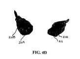
- FIG. 4Dillustrates a close up view of a preferred electrical connection for connecting the heater unit to a power source.
- FIG. 5Aillustrates a top plan view of an alternate embodiment of the cooker of the present invention with the pot, basket and cover removed, and with the cooking pot having step-in means.
- FIG. 5Bshows a cross-sectional view taken along cross-sections line V—V in FIG. 5 A.
- FIG. 6shows an exploded view of the above featured embodiment of the present invention with a “double step-in” cooking fluid volume reduction cooking pot.
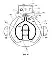
- FIG. 6Ashows a view similar to FIG. 5A with a preferred “double step-in” cooking fluid volume reduction cooking pot and with the temperature sensors removed.
- FIG. 6Bshows a perspective view of “double step-in” cooking fluid volume reduction cooking pot alone.
- FIG. 6Cshows a view similar to FIG. 6A but with an alternate embodiment of the cooking pot.
- FIG. 7shows a cross-section view taken along cross section line VII—VII in FIG. 6A together with a basket inserted.
- FIG. 8shows a bottom plan view of an embodiment of the outer shell of the present invention.
- FIG. 9shows a top plan view of the cooker cover.
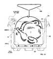
- FIG. 10shows a cross-section view similar to FIG. 7 , but with turkey positioned in the cooking pot prior to lid closure.
- FIG. 11shows a cross-sectional view with the basket in a drain position after cooking the turkey.
- FIG. 12shows a first alternate embodiment of the food support means.
- FIG. 13shows a second alternative embodiment of the food support means.
- FIG. 14shows an additional embodiment of the present invention with an alternate low cooking fluid volume cooking pot.
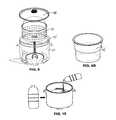
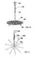
- FIG. 15shows a view of the cooking pot being filled with cooking fluid to a level between the max/min fill range.
- FIG. 16shows an exploded view of an alternate multi-member embodiment of the shell of the present invention.
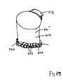
- FIG. 17shows an exploded view of an additional alternate multi-member embodiment of the shell of the present invention.
- FIG. 18shows a notch of shell and tab of cooking pot relationship.
- FIG. 19shows a liner block interconnection between the shell and cooking pot as an alternate to
- FIG. 1A first embodiment of the present invention is shown in FIG. 1 and features a cooking apparatus 20 comprising shell 22 having external wall 24 (includes, for example, a continuously curved wall such as a circle or oval, a multi-sided wall in horizontal cross-section, and/or a wall having interior wall spacing width deviations relative to the vertical direction), base 26 and upper opening 28 leading into interior cavity 30 .
- Shell 22is preferably made of a relatively sturdy material such as steel or a heavy gauge aluminum, and can be either a single wall shell or a laminate or a multi-stack wall as in a double walled shell with or without intermediate insulating material (not shown).
- feet or lift-off meanse.g., individual feet or one or more continuous annular ring members
- base 26e.g., a plurality of spaced apart feet 32 (e.g., three with equal 120° spacing around the circumference as shown in FIG. 8 or six with 60° spacing as partially shown in FIG. 6 ) for preferred cylindrical shell embodiments of the invention.
- Feet 32help promote air flow across the bottom surface of base 26 and spacing separation in general between the heat source (resistor and heated cooking fluid) and underlying support so as to help avoid overheating damage to the underlying support.
- Shell 22further includes grasping handles 34 shown in the figures to be diametrically oppositely positioned within the upper 15% of the height of shell 22 and below the upper bead or edge 36 of shell 22 having notch NT formed over a small portion (e.g., less than 2 inch circumference).
- the height H 1 of the shell from the interior surface 38 of the bottom of shell 22 to upper rim or bead edge 36 and the diameter or average width D 1are sized for the below described accommodation of a container that is itself sized for handling large food items such as an 8 to 18 lb turkey T (See FIGS.
- a preferred height range H 1includes 9 to 20 inches, more preferably 12 to 15 inches with 12.75 inches being well suited based on the additional preferred food sizing characteristics set out below (e.g. a maximum 14 pound turkey recommendation).
- shell diameter D 1(the interior surface diameter or a maximum width value of the interior surface if other than a circular shell configuration is involved) preferably in the range of 10 to 20 inches or more preferably 12 to 18 inches with 15 inches being well suited for the present invention.
- These diameter or peripheral width spacing valuesare well designed to accommodate a container such as the corresponding cooking pot embodiment described below for cooking large single item food objects as in a turkey.
- the preferred volume presented by the interior shell wall (e.g., a preferred cylindrical shape) or walls of the shellis designed for receiving cooking pot 42 which preferably is formed either with a typical cylindrical design as shown in FIG.
- FIG. 1illustrates cooking pot 42 as being designed for receipt inside cavity 30 of shell 22 and preferably being of a height that provides for some degree of overhang relative to the upper rim of the shell, as illustrated by FIGS. 3 and 5B .
- cooking pot 42has bottom 44 (preferably flat on the inner side, but raised or depressed areas on the inner side are also featured under the present invention), side wall 46 (which term is meant to encompass, for example, a single continuous side wall as in a continuous curvature cross-section (circular or oval) or multi-sided configurations as in non-cylindrical configurations and side walls having relative width deviations going in the vertical direction) with interior surface 48 defining upper opening 50 and pot cavity 52 (FIGS. 5 A and 5 B).
- shell 22has an upper edge 36 that preferably includes an upper curved or flat support section to provide a contact support region for overlying flange 54 of cooking pot 42 .
- Flange 54 of pot 42preferably features a first section 55 extending horizontally or more horizontally than vertical and is either planar or curved such as a planar orientation associated with a curved or planar shell upper edge of the shell.
- flange 54further preferably includes a radial outer second flange section 56 that extends vertically or more vertical than the first section 55 .
- the distance between the outer wall surface of the shell's main body, and the interior surface of the flange sectionis preferably designed for providing a limited radial movement potential relationship while, on the other hand, preferably avoiding a tight or difficult to separate interference fit between flange section 56 and the below supporting shell edge 36 (e.g., a radial clearance of 0 (slight contact all around) to 1 ⁇ 8 inch (limited radial adjustment potential).
- This flange nesting relationshiphelps properly align cooking pot 42 within the receiving cavity presented by shell 22 (e.g., establishing an equal radial spacing between the shell and pot at different horizontal cross-sections over the height of the cooking pot as in the upper half to upper quarter of the cooking pot depending on the degree of volume reduction slope in the portions of the cooking pot as described in greater detail below).
- the radial distance of flange 54is of, for example, 0.5 to 1.25 inches in radial width
- a suspension spacing S 4of, for example, 0.25 to 1.25 between the exterior bottom surface of cooking pot 42 and the facing interior bottom surface of shell 22 with a 0.5 inch spacing being well suited for purposes of the invention.
- the suspended cooking potalso preferably has its outer wall surface spaced from the interior side wall of shell 22 (e.g., spacing W 5 of, for example 0.25 to 2.0 inches with 0.75 inch being preferred) which is shown of equal value for more then a majority of the cooking pot height, but can vary as explained below for the cooking fluid volume reduction embodiments and also at the bottom region where cooking pot 42 preferably includes a support step-in means 58 .
- a preferred embodiment of the inventionhas a cooking pot 42 that includes a preferably integrated hereafter “step support” or step-in means 58 providing for basket or food cooking item support and/or cooking fluid volume reduction.
- FIGS. 5A and 5Billustrate a first embodiment of a cooking pot with an integrally formed step support 58 which steps radial in form a location coincident with the bottom of the pot in a preferred embodiment and can take on a variety of forms such as the stepped shoulders 60 , 62 , 64 and 66 arranged in circumferential series along the interior, bottom region within (e.g., a lower quarter) of the side wall 46 of pot 42 , with non-stepped in or recessed areas 61 , 63 , 65 and 67 therebetween as shown in FIG. 5 A.
- Recessed areas 61 , 63 , 65 , and 67provide for improved cooking fluid circulation between the area immediately above interior bottom surface 138 of pot 42 and along the portion of inner surface 48 of pot side wall 46 positioned above step support 58 .
- Recess 67does the same as well as providing access means for heater resistance element 134 . As shown in FIG.
- the stepped shoulders of step-in means 58are preferably designed to facilitate their being formed integrally (e.g., as a process step or component in a pot stamping or shaping process) with, for example, a concave-convex-concave curved bottom cooking pot 42 sequence represented by radius lines R 1 , R 2 and R 3 respectively, or in a less preferred embodiment, suspension inserts (e.g., welded pads) are provided on the shell and/or cooking pot.
- suspension insertse.g., welded pads
- the step-in meansprovide extra support as compared to reliance solely on, for example, the upper flange 54 of cooking pot and bead 36 of shell for support of the cooking fluid and food item and food support means as in a basket received within the pot and preferably positioned so as to avoid direct contact with a heating source positioned between the food support means (e.g., basket) and the bottom of the cooking pot.
- steps such as 62are shown to be greater in circumference than the intermediate recesses such as 63 , this size relationship is reversible with the recesses being circumferentially longer than the steps or equal thereto.
- the steps 62are preferably made smoothly contouring to facilitate the pot forming process and can include divergent or convergent orientations to promote fluid channeling.
- alternate suspension meanssuch as members welded or otherwise fastened to the pot are featured under the present invention, including items that extend through the pot wall before extension into supporting contact relative to the underside or side of the to be positioned basket 70 .
- the integrated step in meansis preferred from ease in manufacturing and in view of the harsh environment of the cooking fluid.
- spacing S 1 between the cooking pot bottom and the bottom of the food support means and/or support contact surface of the step-in means 58preferably ranges from 0.25 to 2 inches, more preferably about 0.5 to 1.5 inches, with 1 inch being a representative value of a preferred embodiment.
- the overall height S 2( FIG.
- width W 1(e.g., the interior diameter above the step-in) of pot 42 is designed to accommodate maximum vertical heights and horizontal dimensions of large food items such as turkeys as well as the typically utilized thin layer of cooking fluid that covers a submerged food item(s) and preferably an additional clearance area that is sufficiently high enough up from the cooking fluid upper layer to help ensure retention of bubbling cooking fluid subjected to a maximum temperature generated by heating element 68 (e.g., a maximum heater control setting of 400° F.) below the cooking pot upper edge 54 .
- a preferred height range for height S 2is one that is less than H 1 to provide the spacing S 4 as in 8.5 to 19.5 inches, more preferably 11 to 15 inches with 12.25 being illustrative of a preferred embodiment height.
- a percentage ratio for S 2 to H 1is preferably 88 to 98%, more preferably 90 to 96% with 96% being an illustrative percentage for a preferred embodiment.
- the difference between the preferably longer H 1 and the preferably lower value S 2is essentially equal to the suspension value S 4 when considering that the upper end of the cooking pot has its flange in contact support with the rim of the cooking pot and its thickness is typically somewhat minimal when considering the overall height of the cooking pot.
- the interior width or diameter W 1 for the side wall portion of cooking pot 42 above suspension means or step-in region 58 shown in FIG. 5 Bpreferably ranges from 9 to 18 inches, with 12 to 16 inches being more preferred and 13.75 inches being illustrative of a preferred embodiment value.
- a preferred embodimentfeatures a cylindrical configuration, with diameter W 1 (for non-cylindrical shapes, W 1 is the average width for the side wall 46 above the step-in region).
- the maximum diameter of the cooking potis represented by W 1 plus two times the flange 54 width (e.g., 15.375 with an 0.8125 inch flange and a 13.75 W 1 value).
- W 2illustrates the width between the interior surface of pot 42 , above any step-in region, and the interior edge of the step-in region 58 such that W 2 is representative of the degree of step in for stepping means 58 .
- This step in distance between the two noted locations represented by W 2is preferably 1 to 4 inches, more preferably 2 to 3 inches with 2.25 inches being illustrative of a preferred embodiment.
- Width W 3( FIG. 5B ) illustrates the width between the outermost step contact point of basket 70 (described below—and while in a concentric cooking position) and the outermost edge of step 58 which coincides in the illustrated embodiment with the cylindrical interior surface of the upper portion of pot 42 shown in FIG. 5 B.
- the interior contact point of W 3is preferably located in an intermediate region of W 2 such as at a 25% to 75% distance out from the outer edge of pot bottom surface 138 coinciding with the interior edge of the step-in region.
- the overall volume of the cooking potis preferably 25 to 35 quarts, more preferably 25 to 29 with 28 or 29 being illustrative of a preferred embodiment. While the arrangement shown in FIG.
- the present inventionalso features alternate lower volume reduction embodiments such as those described below and illustrated in FIGS. 6 , 6 A, 6 B, 6 C to 7 .
- the bottom step in means 58 shown in FIG. 5Bprovides, for example, for a reduction from what would normally be a 30 quart pot to a 29 quart pot (e.g., a reduction of for example 0.5 to 3 quarts via a bottom step in).
- having an upper annular step in and a bottom step in means like 58can provide for even greater cooking fluid volume reduction and provides a reduction in the overall volume of the cooking pot from 30 quarts down to 28 quarts, for example, (e.g., a reduction of for example 1.0 to 4 quarts via a bottom step in and an upper step in), with the upper and lower step ins preferably being below or essentially at the maximum fill line and below the level reached when the food item is inserted.
- An additional embodiment of the present inventionfeatures basket legs 88 (shown in dashed lines) such that the step-in's are optional relative to achieving basket or food support means 70 suspension, but can still be relied upon for volume reduction.
- W 4illustrates a spacing between the outer surface of basket 70 and the inner surface of pot 42 (average if varying as in other than a cylindrical shape) and with the basket 70 preferably being in a concentric arrangement inside the pot. Suitable values for W 4 include 0.5 to 2.0 inches, more preferably 0.75 to 1.5 inches, with 0.875 inches being as illustrative value.
- Width W 5illustrates the spacing (average if varying) between the interior surface of shell 22 and the exterior surface of cooking pot 42 above step-in 58 . Suitable values for W 5 include 0.25 to 1.75 inches, more preferably 0.5 to 1.25 inches, with 0.625 inches being as illustrative value.
- Food support means 70is shown in FIG. 1 as a basket, while FIGS. 12 and 13 illustrate alternate food support means 170 and 270 , respectively.
- basket 70comprises bottom 72 , side wall 74 and upper edge 76 defining food reception opening 78 leading to food reception cavity 80 .
- Side wall 74is preferably provided throughout with side wall apertures 82 (with 3 to 6 vertically spaced circumferentially extending rows of apertures preferred).
- the basketis designed to provide for deep frying heavy objects such as a turkey (including the added weight associated with post cooking absorption of cooking oil) it is preferably formed of unitary metal structure with apertures formed therein and preferably not of low load wire or metal rod screen or mesh arrangements such as in conventional indoor deep fat fryers, although with suitable strength wires the use of mesh is possible under the present invention.
- the basketis formed of relatively thick aluminum (e.g., at least 1.0 mm thick) material. To maintain sufficient strength there is a greater percentage of solid surface than open surface in the areas where apertures are provided. For example, 0.3 to 0.7 inch diameter holes with 0.7 to 1.5 inch minimum spacing between holes.
- the baskethas a side wall that is of sufficient height to adequately retain a large turkey in position (preferably horizontal) within the basket despite the turbulent effects of deep fat frying. For example, a height ratio range of 2:8 to 5:8 relative to the cooking pot.
- a basket height as indicatedis also well suited for steaming typical quantities of seafood such as clams and mussels.
- Bottom apertures 84are additionally provided and are preferably sized and circumferentially serially spaced similar to those in the side wall
- FIGS. 5B and 7further illustrate capture hook 86 shown in full view in FIG. 1 and in cross-section in FIGS. 5B and 7 .
- the aforementioned U.S. Provisional Appln. No. 60/402,912describes a reduced volume outdoor cooking pot having volume reduction means as in radially inwardly extending walls.
- the present inventionsalso includes inwardly directed wall portions or step-in means to help reduce volume of cooking fluid utilized while still accommodating the potential for cooking large food item's as in a turkey and also preferably positioned to double as an underlying basket or food support means contact members.
- An embodiment of the food support meansincludes support means free of any bottom legs.
- there can be relied upon legs designed to make contact with the potthus rendering optional step-in basket suspension means 58 , or intermediate sized bottom legs such as bumps formed in the bottom of the basket for underlying support contact outside of the cooking pot but still relying on shoulder support for suspension above the resistance heater.
- an alternate embodiment of basket 70is shown in FIG. 5B features bottom legs 88 designed to replace step support means 58 or as a supplement thereto (stepped portion 58 used primarily for volume reduction). As shown in FIG.
- optional basket legs 88are designed to suspend the bottom of basket 70 above means for heating 68 and are arranged in a position which avoids contact with the heating means over the full range of possible radial movement between the basket and the pot (e.g., until either the basket outer wall or capture hook 86 contacts the interior of the pot).
- FIG. 12illustrates an alternate embodiment of food support means 170 having a turkey or large food item contact plate 90 having a diameter similar to the bottom of basket 70 so as to rest on the pot's basket suspension means 58 when inserted into pot 42 .
- Food support means 170includes a turkey or food item skewer pole 92 extending up from plate 90 , with plate 90 also including a plurality of apertures 94 .
- Feet 96extend down from plate 90 and are preferably of the intermediate length described above which are suspended above the bottom of pot 42 when plate 90 is resting on suspension means 58 , but which provide for suspension of plate 90 following removal and placement on an external support surface such as a countertop, cooling container or plate (not shown) with the suspension and apertured plate providing for cooling and controlled dripping into a suitable cooling container or plate or absorbent sheet.
- Skewer pole 92features grasping loop 98 which is positioned above the turkey held on the skewer pole and thus provides a grasping location for a grasp handle (see FIG. 10 for an illustration of grasping handle 100 being used as a bailing handle grasping means for basket 70 removal). Suitable indents for the radial ends of the spikes are also preferably provided to properly position the intermediate bump members away from the resistance bar in the event they extend down sufficiently.
- FIG. 13illustrates an alternate food support means 270 having a skewer pole 102 with grasping end 104 and spokes 106 having a radial extension suitable for suspending support means on suspension means 58 of pot 42 .
- Spokes 106are shown to include optional intermediate bump sections 108 which help in suspending the food item to some degree off an underlying post cooking cooling surface (not shown) in the suspension means 58 .
- Various other embodiments of food support meansare also featured under the present invention which preferably are able to accommodate a large food item such as a turkey and retain the food item suspended in the cooking pot either based on coordination in configuration to have a suspension means of the cooking pot suspend the food support means and/or to be self suspension supporting (e.g., legs) either outside of the cooking pot or both in and out of the cooking pot.
- a suspension means of the cooking potsuspend the food support means and/or to be self suspension supporting (e.g., legs) either outside of the cooking pot or both in and out of the cooking pot.
- the height of basket 70is at least 25 percent of the total height of cooking pot 42 and more preferably falls with a range of 2/8 to 7 ⁇ 8 of the cooking pot.
- capture device 86e.g., a capture hook formed with two circumferentially spaced hook prongs
- the dripping fluidreturns close (some absorption involved) to a turkey pre-insertion height level (e.g., a volume of 10 quarts (or the roughly equivalent amount of 10 liters of cooking fluid suitable for a turkey of about 12 to 14 pounds in weight.)
- the capture hookis positioned on the basket such that when it is placed into drainage mode through placement of the capture device into contact with the supporting surface of electric fryer pot 42 , such as the upper flange or bead edge 54 , the under surface of basket 70 is sufficiently off the remaining cooking fluid surface level as to provide for drainage of cooking fluid from the suspended basket.
- FIGS. 10 and 11illustrate these two different cooking fluid states, with FIG. 10 illustrating a cooking mode with turkey T submerged under upper surface level C 1 of cooking fluid C and level C 1 being a distance L 1 below the upper contact surface 54 of the cooking pot in a cooking mode state with the upper end of turkey T submerged or sufficiently close to level C 1 to provide sufficient cooking heat temperature.
- Suitable values for L 1include 3 to 6 inches with 3.75 inches being well suited under the present invention or 20 to 50% of the overall height of pot 42 with 25% being a suitable percentage.
- Distance L 2representing the height from the upper edge of cooking pot 42 to level C 2 of the cooking fluid when the basket and turkey are suspended above C 2 is preferably 5 to 10 inches with 6.75 inches being well suited for uses of the present invention, and with 45 to 65% of the overall height being preferred and with 55% being preferred.
- This level C 2is roughly equivalent (e.g. within an inch or two) to the fluid fill line shown in FIG. 15 (e.g., a 10 quart line although there will be a minimal amount of cooking fluid volume loss due to cooking and food absorption).
- a 10 quart fill lineat about a 5.5 inch height from the bottom of the pot and about 3 inch anticipated clearance for cooking fluid level post turkey insertion leaving about 3.75 inch clearance above the post insertion fluid level to accommodate, for example, foam ups, etc.
- the clearance space between the bottom of suspended basket 70 and the bottom surface 138 of cooking pot 42is shown in FIG. 11 as clearance distance CL and is controlled by the relative position of capture device 86 which is (the contact portion) preferably about 0 (essentially at) to 4 inches from upper edge 76 of basket 70 or more preferably 1 to 3 inches down from upper edge 76 or within an intermediate range of 0 to 45% of the full height of basket 70 .
- An additional feature of basket 70includes clearance recess or groove CR which runs vertically along the side wall of basket 70 between the baskets upper edge and a lower end of the basket (preferably a rectangular cut out CO as shown in FIG. 1 which facilitates the concave protrusion radially inward and preferably extends to the bottom of the basket).
- clearance recess CRis dimensioned to avoid direct contact between the basket and a vertical component of a heating unit 138 ( FIG. 5A ) when the basket is properly oriented such that the recess CR is aligned with the heater portion 138 which is also at a location aligned with notch NT in shell 22 .
- Recess CRis also preferably circumferentially spaced by 90 degrees from the contact ends of bailing handle BH with basket 70 .
- Control unit 112is shown in FIG. 4B to include electric cord receptor 113 which receives connector 114 of electric cord 116 which has on its opposite end standard wall plug 118 .
- Control unit 112includes temperature information supply means 120 (e.g., an electrical LED display or mechanical printed indicia back and with dial, spotter etc.,) designed in conjunction with the desired temperature range to be utilized in the fryer such as a range of 0 to 400° F. or 0 to 450° F. which ranges are well suited for turkey frying and well below a flash point temperature of cooking oils to be used (e.g., peanut oil).
- temperature information supply means 120e.g., an electrical LED display or mechanical printed indicia back and with dial, spotter etc., designed in conjunction with the desired temperature range to be utilized in the fryer such as a range of 0 to 400° F. or 0 to 450° F. which ranges are well suited for turkey frying and well below a flash point temperature of cooking oils to be used (e.g.
- Control unit 112further comprises on/off switch (e.g., pressure button) 122 which has an integrated light such that when the button is placed on the light shines below the button. There is also preferably provided light 124 which turns off from an initial on state when the on button is pressed when a set temperature level is reached or some other signal means (e.g., flashing light and/or audible sound when the level is reached).
- Temperature setting means 128is supported on main housing 126 of control unit 112 and is preferably in the form of a turn dial 128 or an electric temperature setting device such as direction arrow press buttons and/or number touch buttons. Although not shown the interior of main housing 126 supports the electrical connections involved in supplying power for cord 116 to the heater element of the heating unit at the desired level to conform to the temperature set by temperature setting means 128 as well as the safety controlling means described below.
- main housing 126has interior surface 130 which is elongated and arranged essentially vertically, or with a common slope as the supporting outer shell.
- the interior surfacehas means for engagement with shell 22 to help provide a stable relationship.
- connection deviceis comprised of a pair of male projections PR 1 and PR 2 as in T-shaped or oppositely outward arranged C-shaped cross section projections. These projections extend outward toward the shell and are arranged for sliding connection in female reception grooves (GR 1 and GR 2 ) formed in block BL connected to the outer side of shell 22 as shown in FIG. 6 C. Grooves GR 1 and GR 2 have an open top and a blocked off bottom to assist in proper height positioning. Reverse female and male connection arrangements are also featured under the present invention.
- Heater means 68includes main body mounting bracket 132 which is securely fixed to housing 126 and supports heater or resistance element 134 , which in a preferred embodiment is a resistance heater bar which has two prong ends for electrical connection in the control unit's housing.
- Heater element 134is shown to include upper section 136 in a direct supporting relationship with mount 132 and is shaped to extend over and to opposite sides of upper edge or flange 54 of pot, preferably in horizontal fashion in its extension out from mounting bracket 132 .
- Bracket 132is provided to secure heater element in a preferred generally concentric spacing relative to the interior side wall of the pot (i.e., preferably both a side wall spacing and a suspension arrangement relative to the bottom surface of the pot).
- notch NTprovides a clearance location for the passage of the two prongs of the shaped resistance bar extending over the upper edge of notch NT into its reception area of main housing 126 .
- a tab memberthat is provided by way of a pair of circumferentially spaced cuts and a bending down to, for example, 45 degrees and a bending of any radially outward overextending portion down against the side of the shell. This arrangement is shown in FIG. 18 and helps in locking the two components together and helps in covering over a gap in between the shell and cooking pot.
- FIG. 18shows an alternate embodiment shown in FIG.
- connection block liner BR 1which is designed for a male/female connection with a corresponding connection block BR 2 provided by the cooking pot as in a downwardly extending block member sections (spaced apart to accommodate the upper, horizontal components of the resistance heater bar).
- Heater element 134further includes more vertical intermediate section 138 (true vertical or, close to true vertical ( ⁇ 10°), or with a slope corresponding or within 10° to the adjacent most surface of cooking pot 42 when the heater device is in operational position) which extends for essentially the full length of the interior surface of cooking pot but for a bottom of pot clearance spacing as shown in FIG. 5B of, for example, a spacing SB of 0.125 to 0.750 inch above the interior bottom surface of pot 42 , which is suitable to avoid direct pot contact and provide some degree of cooking oil circulation under the heating element bottom section 140 .
- the overall vertical length of section 138is essentially equal to the height of pot 42 but for the clearance spacing of SB between the lower edge of the bottom heater section 140 and the bottom of the cooking pot.
- Heater element 134further has its bottom section 140 designed to extend in parallel fashion above the bottom 138 of pot 42 .
- Connection bracket 132is preferably U-shaped and has an enlarged upper wall 144 which is sufficiently sized as to bridge the notch NT in shell 22 and can either be curved to correspond with the curvature of the shell or not curved since the notch is relatively small 2.0 inches or less in circumferential or length.
- Connection bracket 132features fastener reception hole for receiving fastener FT (e.g. a screw designed to connect with an underlying component of the assembly or a clamp combination with underside of an adjacent shell flange).
- fastener FTe.g. a screw designed to connect with an underlying component of the assembly or a clamp combination with underside of an adjacent shell flange.
- enlarged upper wall 144extends into front and back three prong arm sections 146 and 148 . Each three prong set defines two intermediate slots spaced apart by a middle prong in the set. As seen from FIGS.
- heater element 134has a pair of generally horizontal leads that extend from the above noted electrical contact prongs positioned within the control housing and which are further supported by strengthening plate 142 .
- Each of the resistance lead portionsform one half of upper section 136 in its extension out from mounting bracket 132 .
- FIGS. 4A and 5Athus illustrate a first embodiment of heater element 134 having an upper section 136 that features resistance element segments 150 , 152 that extend into prongs (not shown) within housing 126 and into electrical communication with the interior control elements (internal controls know per se and thus also not shown).
- the interior control elementsestablish a desired heating level based on controlling the output from the electric outlet energy source to the illustrated resistance heater unit 134 in accordance with the setting established by temperature control dial or temperature control setting means 128 .
- one of segments 150 , 152is an electrical output line segment and the other an electrical input line segment for the continuous resistant heater element 134 .
- Segment 150is of a radial length suitable to clear the upper rim of both the cooking pot 42 and shell 22 and leads into a first ( 151 ) of two smooth concave (opens down) interface segments 151 and 153 .
- Concave heater element segment 151(which is bisected by a vertical plane) extends down into a first vertical segment 154 of the pair of more vertical segments 154 , 156 which together form more vertical intermediate heater section 138 .
- segments 154 and 156are more vertical than segments 150 , 152 and they extend down from the level of the respective more horizontal segments 150 and 152 for preferably at least 90% of the overall pot 42 height.
- Segments 154 and 156are also shown to extend in parallel fashion down from their upper smooth convex curve interface 151 , and 153 with the inner pot ends of segments 150 , 152 . Also any length values for the horizontal and vertical sections are defined on the basis of inclusion of any interface section that extends from an intermediate point of bending along the interface section into the section whose length is being referenced.
- intermediate section 138i.e., the lower ends of the vertical segments 154 and 156 interfaces with bottom section 140 by way of a double curve combination on each side with the first curved interface section in each combination including a convex (opens upward and is bisected by the same vertical plane bisecting the corresponding upper curved interface) intermediate section ( 155 and 157 ) and a second curved interface section ( 159 and 161 ) in each combination includes a generally horizontal curved section (bisected by a horizontal plane) opening radially outward such that the immediately adjacent respective portions of the bottom section extend outward from the intermediate section to initiate a curvature that corresponds to some degree to the curvature (or peripheral extension) of the cooking pot in which the bottom section is received and suspended above the cooking pots lower surface 138 .
- a preferred embodimentincludes a horseshoe shaped bottom heater section 140 featuring a first side outer curved portion 158 having a curvature that preferably generally conforms (e.g., is concentric) over a majority of the side length of the heater and/or a quadrant of the cooking pot curvature as in the case of a cylindrical step-in portion or is close to concentric as in an inch or two or less of radial deviation relative to the spacing to the outer radially adjacent point on the cooking pot for the noted majority and/or quadrant of the cooking pot.
- a straight line step inis featured as in FIG. 6A the concentric arrangement is relative to the curved area of the cooking pot above the step in.
- first side outer curved portionextends in common or generally common curvature for 50 to 100% of the 180 degrees represented by the diametric line D extending midway between the vertical segments 154 and 156 and more preferably 70 to 95% of the same.
- the heater element “halves” 164 , 166 having respective outer curved sections 158 , 160are preferably symmetrical when the cooking pot configuration is symmetrical.
- each of sections 158 and 160generally conforms to the that of the cooking pot and the spacing S 6 is preferably between 1 and 3 inches with 1.5 or 1.75 relative to the most interior step in edge being well suited for use with a cooking pot having a W 1 value (e.g., diameter shown in FIG. 5B ) of 13.75 such that heater spacing S 6 .
- the suspended heater relationshipcan be seen in the plan view provided in FIG. 5B showing the heater element 134 held in a suspended state relative to both cooking pot 42 and supporting outer shell 22 .
- the length of the segments in a direction parallel to line Dis preferably about 75 to 95 of W 1 while a spacing width for the opposing parallel extending inner heater bar segments taken along a line extending transverse to line D is preferably about 15 to 40% of width W 1 , with 20 to 25% being preferred.
- FIG. 4Ashows heater element halves 164 , 166 having inward extensions 169 , 171 , extend inwardly from outer most edges sections 168 , 170 generally parallel and spaced to opposite sides of the diametric line D as noted above and are spaced from line D (e.g., 0.75 to 2 inches) and merge to form an integrated or monolithic heater bar at internal curve section 174 .
- Sensor frame support 176extends between and is connected at opposite ends to respective inward extensions 169 , 171 and hold first and second sensors 178 , 180 which are preferably thermistor temperature sensors with different temperature control settings and in communication with control unit 112 via sensor lines 182 , 184 which are banded to one of the vertical heater sections (e.g., 154 ) so as to avoid dangling and potential catching of the sensor wires 184 , 186 .
- first and second sensors 178 , 180which are preferably thermistor temperature sensors with different temperature control settings and in communication with control unit 112 via sensor lines 182 , 184 which are banded to one of the vertical heater sections (e.g., 154 ) so as to avoid dangling and potential catching of the sensor wires 184 , 186 .
- Temperate sensors 178 , 180are preferably designed for different functions with one of the two (e.g., sensor 178 ) sensing temperature and in communication with a control unit sub-system (not shown) that is also in communication with the temperature setting means 128 and current temperature display means 120 such that the sensor 178 senses current oil temperature at the bottom of the pot and control unit 112 determines whether additional electric current needs to be supplied to raise the oil temperature or whether a lowering or discontinuation of current supply is warranted to avoid overheating relative to the set temperature.
- control unitsends a signal to display means 120 to display the current sensed temperature within a preferred display ranges of for example 0 to 400° F.
- the second of the two sensorsis preferably a fail safe sensor which shuts down all power if a high temperature is sensed (e.g., 450° F. or 475° F.)
- a high temperaturee.g., 450° F. or 475° F.
- This failsafe featuresis well below the ignition temperature of cooking fluids such as peanut oil (e.g., below 600° F.)
- FIG. 4Billustrates the outer face of main body 126 which includes a reset button RB that allows for a re-initializing of the control unit and heater elements when the temperature drops below the second sensor threshold.
- the cooking pot 42is inserted into shell 22 followed by the attachment of heating means 68 such that bottom heater element section 140 is suspended above the bottom of the cooking pot 42 , and control unit 112 is properly and stably supported by the combined cooking pot and shell flanges/upper bead combination preferably in conjunction with notch NT as well as projections PR 1 and PR 2 noted above.
- control unit 112is properly and stably supported by the combined cooking pot and shell flanges/upper bead combination preferably in conjunction with notch NT as well as projections PR 1 and PR 2 noted above.
- the basket volumeis shown designed to receive for example a 14 pound turkey in contacting fashion (e.g.
- the diameter of the basketis made to generally correspond with the average length of a turkey at 14 pounds weight).
- Suitable cooking fluid as in cooking oil for a turkey or water for shellfishis supported up to the fill line (e.g., 10 quart amount).
- the control unit's temperature setting means 128is then adjusted to a desired temperature level (e.g., 350° F. which is a setting suitable for cooking a whole turkey).
- a desired temperature levele.g., 350° F. which is a setting suitable for cooking a whole turkey.
- the turkeyis placed within cooking basket 70 preferably in a horizontal arrangement and the basket and turkey are slowly placed in the cooking fluid with the assistance of handle 100 after the cooking fluid is displayed as having reached the set level (preferably by way of sensed temperature amount display at 120 and the turning on of a signal as in a light (DS) off and/or audible signal).
- the cover 188is then placed on and the cooking time monitored. Pre-insertion while the cooking fluid is cool is also possible under the present invention with an appropriate extension of time under the above formula.
- the cookeris turned off (e.g., unplugged) (either automatically by the control unit or manually) and the cover removed and then the basket (or alternate food supporting means) is removed with the assistance of grasping handle 100 as shown in FIG. 10 .
- the basketis lifted sufficiently high enough for catching grasping hook 86 on the side of the combination cooking pot and shell flange/upper rim.
- the turkeyis then removed to a suitable food preparation area.
- the cooking fluidcan be properly dispensed (e.g., an oil receptacle).
- the earlier exposed heating means 68 sensor casings and control unit housingare then preferably cleaned with a damp cloth or sponge using a mild soap. The remainder of the non-electrical components being dishwasher safe following disassembly.
- FIGS. 6A-6C and 7a illustrate an alternate embodiment of the invention showing multi-step-in cooking pot configurations designed to reduce volume while still providing for both heater element and cooking basket placement and side edge clearance
- FIG. 6Billustrates a similar arrangement shown in FIG. 5A but for there being provided an even further cooking fluid volume reduction embodiment wherein cooking pot 200 features step-ins of variable radial extension so as to provide support to the basket or alternate food support means.
- the radial thickest portionsare shown to the left and right step ins Q 1 and Q 2 relative to a central positioned control unit and a diametrically opposite region Q 3 which is the thickest region and preferably as a convex inner edge (while the other step-ins Q 1 and Q 2 are preferably straight edge).
- the radially inward curved extension wall of step Q 3preferably in centrally positioned relative to the open end of the horseshoe shaped horizontal portion of the heater resistance bar shown.
- hook 86is shown to extend down to a location above the upper step-in 202 and preferably within an inch or two thereof.
- FIG. 6Aalso illustrates the generally concentric relationship between the outer curved edges 158 and 160 relative to the upper portion of cooking pot 42 ′ (the prime representative of the double level step-in arrangement) while the lower interiormost edges of lower step-ins Q 1 to Q 3 extend in closer relative to the heater units horizontal portion 140 .
- dimensions DI, DJ and DKillustrate some of the relative spacing between heater bar 140 and the interior surfaces of the step-ins.
- DIshows the relative spacing between the straight edge of step-in Q 1 and the tangential, closest surface of heater bar 134 (by way of transverse line DI) as being intermediate the smaller spacing distance DK and the larger spacing DJ (with the same spacing DI being true for step-in Q 2 ).
- the smallest spacing DKis between a line extending transverse to the tangential, closest spaced line extending of the closest point of the heater unit adjacent thereto.
- DJillustrates the transverse distance between the inner surface immediately below the annular step in 202 and a tangential line of the heater bar portion closest thereto.
- the annular thickness or radial depth of step-in 202is preferably about 0.25 to 1 inch with 0.5 inch being preferred.
- Block BLinto which the main housing 126 of the heater unit is slid by way of grooves GR 1 and GR 2 , is illustrated in its mounted position on the exterior side of the shell 22 .
- the electrical connection extending from the housing 126 of the heater unitis preferably of a design that precludes too easy detachment (a problem associated with some prior art designs relying on magnetic attachment).
- the present inventionpreferably includes a first electrical connector 204 ( FIG. 4B ) extending from a relatively short “pig tail” wire 206 which is free to rotate at the housing 126 connection.
- the connector end 208is preferably a female receptor with internal male prongs 209 similar to the main power connection to a personal computer and with receptor end 210 being the insertable male component into the connector end while having female receptors 211 .
- This connection used in the present settingprovides for sufficient attachment without undesirable detachment.
- FIGS. 16 and 17show exploded views of alternate shell embodiments of the present invention, with FIG. 16 showing shell 22 ′ being formed of a combination upper ring 212 (preferably plastic formed by injection molding and shown in cut-away in FIG. 16 ) providing the contact bead or flange on which the cooking pot rests, intermediate shell wall 214 (e.g.
- the upper and lower ringsare securely fastened to respective upper and lower ends of the shell wall (e.g., mechanical fastening via added fastening members or a mechanical interrelationship between the two such as in an overmolding process with catch tabs.
- FIG. 17shows a similar view as that of FIG. 16 except that rather than a lower ring 216 there is provided a lower cup member 220 having a continuous surface wall 222 for contact with the bottom of the cooking pot (preferably with a series of grooves and ribs 224 as well as ventilation ports for heat reduction in the contact area of the cooking pot (thus a high temperature plastic is preferably used) or a combination of plastic base and an upper high temperature intermediate laminate (not shown) between the base and the cooking pot to be inserted into the shell.
- a lower cup member 220having a continuous surface wall 222 for contact with the bottom of the cooking pot (preferably with a series of grooves and ribs 224 as well as ventilation ports for heat reduction in the contact area of the cooking pot (thus a high temperature plastic is preferably used) or a combination of plastic base and an upper high temperature intermediate laminate (not shown) between the base and the cooking pot to be inserted into the shell.
Landscapes
- Engineering & Computer Science (AREA)
- Food Science & Technology (AREA)
- Cookers (AREA)
- Frying-Pans Or Fryers (AREA)
Abstract
Description
Claims (32)
Priority Applications (9)
| Application Number | Priority Date | Filing Date | Title |
|---|---|---|---|
| US10/640,691US6941857B2 (en) | 2002-08-14 | 2003-08-14 | Cooking apparatus |
| CA2535012ACA2535012C (en) | 2003-08-14 | 2004-08-13 | Cooking apparatus |
| US10/917,418US7412922B2 (en) | 2002-08-14 | 2004-08-13 | Cooking apparatus |
| PCT/US2004/026382WO2005016091A1 (en) | 2003-08-14 | 2004-08-13 | Cooking apparatus |
| CN200480029879.7ACN101119664B (en) | 2003-08-14 | 2004-08-13 | Cooking device |
| US11/141,194US7981459B2 (en) | 2002-08-14 | 2005-06-01 | Cooking apparatus |
| US11/415,415US7703389B2 (en) | 2003-08-14 | 2006-05-02 | Cooking apparatus with cooking characteristic monitoring system |
| US12/219,456US20090087534A1 (en) | 2002-08-14 | 2008-07-22 | Cooking apparatus |
| US13/155,666US20120009317A1 (en) | 2002-08-14 | 2011-06-08 | Cooking apparatus |
Applications Claiming Priority (2)
| Application Number | Priority Date | Filing Date | Title |
|---|---|---|---|
| US40291202P | 2002-08-14 | 2002-08-14 | |
| US10/640,691US6941857B2 (en) | 2002-08-14 | 2003-08-14 | Cooking apparatus |
Related Child Applications (3)
| Application Number | Title | Priority Date | Filing Date |
|---|---|---|---|
| US10/917,418ContinuationUS7412922B2 (en) | 2002-08-14 | 2004-08-13 | Cooking apparatus |
| US10/917,418Continuation-In-PartUS7412922B2 (en) | 2002-08-14 | 2004-08-13 | Cooking apparatus |
| US11/141,194DivisionUS7981459B2 (en) | 2002-08-14 | 2005-06-01 | Cooking apparatus |
Publications (2)
| Publication Number | Publication Date |
|---|---|
| US20040103795A1 US20040103795A1 (en) | 2004-06-03 |
| US6941857B2true US6941857B2 (en) | 2005-09-13 |
Family
ID=34193600
Family Applications (3)
| Application Number | Title | Priority Date | Filing Date |
|---|---|---|---|
| US10/640,691Expired - LifetimeUS6941857B2 (en) | 2002-08-14 | 2003-08-14 | Cooking apparatus |
| US11/141,194Active2026-10-05US7981459B2 (en) | 2002-08-14 | 2005-06-01 | Cooking apparatus |
| US13/155,666AbandonedUS20120009317A1 (en) | 2002-08-14 | 2011-06-08 | Cooking apparatus |
Family Applications After (2)
| Application Number | Title | Priority Date | Filing Date |
|---|---|---|---|
| US11/141,194Active2026-10-05US7981459B2 (en) | 2002-08-14 | 2005-06-01 | Cooking apparatus |
| US13/155,666AbandonedUS20120009317A1 (en) | 2002-08-14 | 2011-06-08 | Cooking apparatus |
Country Status (4)
| Country | Link |
|---|---|
| US (3) | US6941857B2 (en) |
| CN (1) | CN101119664B (en) |
| CA (1) | CA2535012C (en) |
| WO (1) | WO2005016091A1 (en) |
Cited By (64)
| Publication number | Priority date | Publication date | Assignee | Title |
|---|---|---|---|---|
| US20050232075A1 (en)* | 2004-04-15 | 2005-10-20 | Pauline Kistela | Feed preparation device & method of use thereof |
| US20060151464A1 (en)* | 2002-10-31 | 2006-07-13 | Wilson Ian G | Deep frying appliance |
| US20060201336A1 (en)* | 2005-03-12 | 2006-09-14 | Williams Hilton A | Fry pot splatter shield |
| US20060254432A1 (en)* | 2003-08-14 | 2006-11-16 | Mclemore John D | Cooking apparatus with cooking characteristic monitoring system |
| US20060289443A1 (en)* | 2005-05-11 | 2006-12-28 | Wang Dong-Lei | Household electric heating cooker with detachable power outlet |
| USD552921S1 (en) | 2007-01-16 | 2007-10-16 | Hamilton Beach/Procter-Silex, Inc. | Deep fryer |
| USD553432S1 (en)* | 2007-03-16 | 2007-10-23 | Test Rite International Company, Ltd. | Fryer rack |
| US20080277558A1 (en)* | 2007-05-07 | 2008-11-13 | Litwin Christopher J | Adjustable Support Device |
| US20090078127A1 (en)* | 2004-12-23 | 2009-03-26 | Mclemore Don | Cooking device |
| US20090205511A1 (en)* | 2008-02-18 | 2009-08-20 | Tienor Lawrence J | Methods and apparatus for accelerating cooling of a countertop deep fryer |
| US20100275897A1 (en)* | 2009-04-30 | 2010-11-04 | The Brinkmann Corporation | Gas cooking appliance having an automatic gas shutoff mechanism |
| US20110081471A1 (en)* | 2009-10-01 | 2011-04-07 | Mclemore Don | Cooking Apparatus |
| USD642421S1 (en)* | 2011-02-18 | 2011-08-02 | Agostino Difante | Combined cooking device |
| US8067716B1 (en)* | 2005-02-03 | 2011-11-29 | Lloyd Ernest L | Cooking apparatus |
| USD653074S1 (en)* | 2011-09-20 | 2012-01-31 | Agostino Difante | Combined oblong cooking device |
| USD653073S1 (en)* | 2011-08-02 | 2012-01-31 | Agostino Difante | Combined cooking device |
| USD658424S1 (en)* | 2011-11-21 | 2012-05-01 | Agostino Difante | Combined cooking device |
| USD658425S1 (en)* | 2012-01-09 | 2012-05-01 | Agostino Difante | Combined cooking container |
| US8186265B2 (en) | 2005-08-08 | 2012-05-29 | Ron's Enterprises, Inc. | Device to efficiently cook food |
| US20120167778A1 (en)* | 2005-08-08 | 2012-07-05 | Popeil Ronald M | Device to efficiently cook foods using liquids and hot vapors |
| USD687257S1 (en)* | 2013-01-28 | 2013-08-06 | Agostino Difante | Combined stock pot with vented strainer |
| USD687256S1 (en)* | 2013-01-28 | 2013-08-06 | Agostino Difante | Combined stock pot with slotted strainer |
| US8707857B2 (en) | 2005-08-08 | 2014-04-29 | Ronald M. Popeil | Cooking device to deep fat fry foods |
| US20140209598A1 (en)* | 2011-07-13 | 2014-07-31 | Seb S.A. | Cooking Pot with a Heated Lateral Wall and Process |
| US8850965B2 (en) | 2005-08-08 | 2014-10-07 | Ronald M. Popeil | Device to efficiently cook food |
| US8939068B2 (en) | 2010-04-29 | 2015-01-27 | Landmann Usa | Multiple drawer smoker |
| USD755012S1 (en)* | 2015-01-22 | 2016-05-03 | Blue Rhino Global Sourcing, Inc. | Fryer basket |
| US20160206152A1 (en)* | 2015-01-09 | 2016-07-21 | Anthony Allen Garrett | Egg Press |
| US20160278562A1 (en)* | 2013-12-05 | 2016-09-29 | Sammi Industrial Co. | Double cooking container having improved stability and heating efficiency |
| USD789731S1 (en)* | 2015-10-07 | 2017-06-20 | Peiying Feng | Oven |
| USD806334S1 (en)* | 2016-11-16 | 2017-12-26 | Silvia M. DiSabatino | Laundry device |
| US10188120B2 (en) | 2010-04-29 | 2019-01-29 | Landmann Usa | Multiple drawer smoker |
| US10258192B1 (en)* | 2016-10-17 | 2019-04-16 | Magellan Home Goods, Ltd. | Cooking utensil |
| USD850200S1 (en)* | 2018-11-02 | 2019-06-04 | Shenzhen Jiying Technology Co., Ltd. | Steamer basket |
| US20190231126A1 (en)* | 2017-08-09 | 2019-08-01 | Sharkninja Operating Llc | Cooking device and components thereof |
| US10412981B2 (en) | 2017-02-27 | 2019-09-17 | Ronald M. Popeil | System and method for deep frying poultry while avoiding skin damage |
| USD865445S1 (en)* | 2019-07-18 | 2019-11-05 | Shenzhen Wan Si Tuo Trading Co., Ltd. | Stainless steel steam basket |
| USD869903S1 (en) | 2019-07-19 | 2019-12-17 | Ruiping Zhong | Multi-function cooking basket |
| USD873602S1 (en) | 2018-08-09 | 2020-01-28 | Sharkninja Operating Llc | Lid part of a food preparation device |
| USD874211S1 (en) | 2018-08-09 | 2020-02-04 | Sharkninja Operating Llc | Food preparation device and parts thereof |
| US10624358B2 (en) | 2017-12-05 | 2020-04-21 | Lem Products Holding Llc | Electric smoker |
| USD884422S1 (en) | 2020-01-22 | 2020-05-19 | Ruiping Zhong | Multi-function cooking basket |
| USD903415S1 (en) | 2018-08-09 | 2020-12-01 | Sharkninja Operating Llc | Cooking basket |
| USD910951S1 (en) | 2019-11-19 | 2021-02-16 | Mr. Bar-B-Q Products Llc | Scraper |
| USD914436S1 (en) | 2018-06-19 | 2021-03-30 | Sharkninja Operating Llc | Air diffuser with food preparation pot |
| USD918655S1 (en)* | 2020-11-18 | 2021-05-11 | Wenjie Lin | Steamer |
| USD918654S1 (en) | 2019-06-06 | 2021-05-11 | Sharkninja Operating Llc | Grill plate |
| USD922126S1 (en) | 2019-06-06 | 2021-06-15 | Sharkninja Operating Llc | User interface for a food preparation device |
| US11033146B2 (en) | 2019-02-25 | 2021-06-15 | Sharkninja Operating Llc | Cooking device and components thereof |
| US11134808B2 (en) | 2020-03-30 | 2021-10-05 | Sharkninja Operating Llc | Cooking device and components thereof |
| USD932833S1 (en) | 2018-08-09 | 2021-10-12 | Sharkninja Operating Llc | Reversible cooking rack |
| USD968891S1 (en) | 2021-03-18 | 2022-11-08 | Mr. Bar-B-Q Products Llc | Grilling basket |
| USD981731S1 (en) | 2022-02-03 | 2023-03-28 | Mr. Bar-B-Q Products Llc | Grill brush |
| USD981728S1 (en) | 2021-08-23 | 2023-03-28 | Mr. Bar-B-Q Products Llc | Grill brush |
| USD981730S1 (en) | 2021-08-27 | 2023-03-28 | Mr. Bar-B-Q Products Llc | Grill brush |
| USD981727S1 (en) | 2021-08-23 | 2023-03-28 | Mr. Bar-B-Q Products Llc | Grill brush |
| USD981725S1 (en) | 2021-08-13 | 2023-03-28 | Mr. Bar-B-Q Products Llc | Grill brush |
| USD981729S1 (en) | 2021-08-27 | 2023-03-28 | Mr. Bar-B-Q Products Llc | Grill brush |
| USD981726S1 (en) | 2021-08-13 | 2023-03-28 | Mr. Bar-B-Q Products Llc | Grill brush |
| USD992397S1 (en) | 2021-12-01 | 2023-07-18 | Mr. Bar-B-Q Products Llc | Tool handle |
| US11751710B2 (en) | 2019-02-25 | 2023-09-12 | Sharkninja Operating Llc | Guard for cooking system |
| US12035725B2 (en) | 2022-12-12 | 2024-07-16 | Sharkninja Operating, Llc | Grill systems |
| US12070042B2 (en) | 2022-12-12 | 2024-08-27 | Sharkninja Operating Llc | Grill systems |
| USD1063483S1 (en) | 2023-06-15 | 2025-02-25 | Sharkninja Operating Llc | Cooking device |
Families Citing this family (32)
| Publication number | Priority date | Publication date | Assignee | Title |
|---|---|---|---|---|
| US7412922B2 (en)* | 2002-08-14 | 2008-08-19 | Mclemore John D | Cooking apparatus |
| US6941857B2 (en) | 2002-08-14 | 2005-09-13 | Mclemore John D. | Cooking apparatus |
| USD516374S1 (en) | 2003-08-14 | 2006-03-07 | Mclemore John D | Cooking apparatus |
| USD560424S1 (en) | 2003-08-14 | 2008-01-29 | Mclemore John D | Cooking fluid cooking apparatus |
| CN2735702Y (en)* | 2004-05-21 | 2005-10-19 | 王冬雷 | A totally detachable electric heating device |
| US20180049590A1 (en)* | 2016-04-29 | 2018-02-22 | Alan Backus | Devices and methods for supporting and preparing foods |
| US20170311757A1 (en)* | 2016-04-29 | 2017-11-02 | Alan Backus | Devices and methods for supporting and preparing foods |
| US20190281869A1 (en)* | 2018-03-14 | 2019-09-19 | Alan Backus | Method to cook fowl and other unitary foods |
| US8066427B2 (en)* | 2006-06-12 | 2011-11-29 | Don Wong | Stirring and mixing apparatus |
| US20100196652A1 (en)* | 2009-02-03 | 2010-08-05 | Demien Jacquinet | Quasi-isotropic sandwich structures |
| US8424521B2 (en)* | 2009-02-27 | 2013-04-23 | Covidien Lp | Leak-compensated respiratory mechanics estimation in medical ventilators |
| SG184919A1 (en)* | 2010-04-28 | 2012-11-29 | Sharp Kk | Cooking device |
| CN202960039U (en)* | 2012-06-11 | 2013-06-05 | 佛山市顺德区智创达电器制造有限公司 | Cooking pot provided with rotating rolling steamer |
| FR2992156B1 (en)* | 2012-06-26 | 2014-06-13 | Seb Sa | APPARATUS FOR FONDUE AND STEAM COOKING |
| US10064521B1 (en)* | 2014-01-15 | 2018-09-04 | Yantra, Llc | Automated multi-dish cooking machine |
| CN104771056A (en)* | 2015-01-04 | 2015-07-15 | 杨小平 | Uniform heating method for cooking plain chicken and cooker |
| FR3034973B1 (en)* | 2015-04-17 | 2017-11-03 | Seb Sa | COOKING ACCESSORY AND ELECTRIC COOKING APPARATUS HAVING A COOKING ACCESSORY |
| CN106308567B (en)* | 2015-06-30 | 2020-07-31 | 浙江绍兴苏泊尔生活电器有限公司 | Temperature sensing device and electric fryer |
| CN105433752A (en)* | 2015-11-18 | 2016-03-30 | 无锡科诺达电子有限公司 | Spiral twisting type colander |
| CN205963849U (en)* | 2016-05-24 | 2017-02-22 | 飞利浦(中国)投资有限公司 | Air fryer |
| CN107773017B (en)* | 2016-08-25 | 2023-04-07 | 浙江苏泊尔家电制造有限公司 | Cooking utensil |
| CN106912513A (en)* | 2016-11-22 | 2017-07-04 | 湖北香江电器股份有限公司 | Oil drum and the deep frying pan with the oil drum |
| KR101864514B1 (en) | 2016-12-27 | 2018-06-04 | 엘지전자 주식회사 | Combination cooking appliance |
| JP6862314B2 (en)* | 2017-08-30 | 2021-04-21 | 日立グローバルライフソリューションズ株式会社 | rice cooker |
| AU2018338437A1 (en)* | 2017-09-25 | 2020-03-05 | Henny Penny Corporation | High limit RTD holder block |
| CN110353470A (en)* | 2018-04-10 | 2019-10-22 | 浙江苏泊尔家电制造有限公司 | Cooking apparatus, culinary art method and computer storage medium |
| CN108324090A (en)* | 2018-04-16 | 2018-07-27 | 广东天际电器股份有限公司 | A kind of same shaft multifunctional detection stews device |
| EP4267884A1 (en)* | 2020-12-24 | 2023-11-01 | Koninklijke Philips N.V. | Steam cooking apparatus |
| CN113331683B (en)* | 2021-06-10 | 2024-12-20 | 遨博(北京)智能科技股份有限公司 | A cooking mechanism |
| CN215899396U (en)* | 2021-07-09 | 2022-02-25 | 佛山市顺德区美的电热电器制造有限公司 | Cooking utensil |
| KR102385041B1 (en)* | 2021-12-07 | 2022-04-11 | 주식회사 솔인 | Smoked barbecue equipment combined use hot and cold storage |
| EP4342344A1 (en)* | 2022-09-21 | 2024-03-27 | Versuni Holding B.V. | Kitchen apparatus for accommodating a wired food monitoring sensor |
Citations (47)
| Publication number | Priority date | Publication date | Assignee | Title |
|---|---|---|---|---|
| US2032175A (en)* | 1933-04-12 | 1936-02-25 | Jones Metal Products Company | Cooking apparatus |
| US2215929A (en)* | 1939-10-12 | 1940-09-24 | Electricooker Inc | Cooking machine |
| US2597695A (en)* | 1951-05-03 | 1952-05-20 | Dormeyer Corp | Cooking utensil |
| US2785277A (en)* | 1952-10-22 | 1957-03-12 | Sunbeam Corp | Automatic cooking device |
| DE3143863A1 (en) | 1981-11-05 | 1983-05-11 | Robert Krups Stiftung & Co KG, 5650 Solingen | Electric deep fat fryer |
| DE3150455A1 (en) | 1981-12-19 | 1983-06-30 | Robert Krups Stiftung & Co KG, 5650 Solingen | Deep-fat fryer with an electrically heatable frying pot |
| DE3221433A1 (en) | 1982-06-07 | 1983-12-08 | Robert Krups Stiftung & Co KG, 5650 Solingen | Electric deep fat fryer |
| EP0143885A1 (en) | 1983-11-03 | 1985-06-12 | ROBERT KRUPS STIFTUNG & CO. KG. | Electric fryer |
| US4798939A (en)* | 1986-04-02 | 1989-01-17 | Gallina Corporation | Pressurized liquid cooker with integrated radiant heating apparatus |
| US4968516A (en)* | 1989-07-24 | 1990-11-06 | Thompson Neal W | Method and apparatus for cooking foodstuffs using auxiliary steam |
| EP0432370A1 (en) | 1989-12-14 | 1991-06-19 | Robert Krups GmbH & Co. KG | Electric fryer |
| US5172328A (en) | 1988-04-01 | 1992-12-15 | Restaurant Technology, Inc. | Food preparation system and method |
| US5379684A (en) | 1991-10-29 | 1995-01-10 | Moulinex Swan Holding Limited | Deep fryer |
| US5400700A (en)* | 1991-07-30 | 1995-03-28 | Bois; Bernard M. | Electrical cooking apparatus and its method of manufacture |
| US5429039A (en) | 1994-08-26 | 1995-07-04 | Chang; Kwei T. | Multipurpose cooker |
| USD365723S (en) | 1993-02-05 | 1996-01-02 | Seb | Electric deep fat fryer |
| USD378647S (en) | 1994-12-06 | 1997-04-01 | Moulinex S.A. | Electric deep fat fryer |
| US5651905A (en) | 1995-06-07 | 1997-07-29 | The West Bend Company | Heating device for a small appliance |
| US5718934A (en) | 1993-10-04 | 1998-02-17 | Hayakawa; Hideo | Deep frying method |
| US5758569A (en) | 1996-03-28 | 1998-06-02 | Barbour International | Poultry frying apparatus |
| US5794522A (en) | 1996-04-11 | 1998-08-18 | Moulinex S.A. | Electrical cooking apparatus, in particular deep fat dryer |
| US5973297A (en) | 1996-03-28 | 1999-10-26 | Henny Penny Corporation | Apparatus and method for heat regulation of deep fat fryer |
| US6002111A (en) | 1994-08-17 | 1999-12-14 | Seb S.A. | Heating device for foodstuffs, particularly for frying, with an outer bowl |
| US6006658A (en) | 1999-04-30 | 1999-12-28 | Siu; Chong Fu | Electrical deep fryer |
| USD424366S (en) | 1998-10-15 | 2000-05-09 | Moulinex S.A. | Electric deep fat fryer |
| USD431150S (en) | 2000-01-18 | 2000-09-26 | National Presto Industries, Inc. | Electric deep fryer |
| US6138552A (en) | 1996-02-22 | 2000-10-31 | Moulinex S.A. | Electric deep fryer and cooking control method therefor |
| US6240835B1 (en) | 1998-02-25 | 2001-06-05 | Moulinex S.A. | Electric cooking appliance in particular deep fryer |
| USD444666S1 (en) | 2000-11-27 | 2001-07-10 | National Presto Industries, Inc. | Electric deep fryer with divider |
| US6262398B1 (en) | 1997-11-28 | 2001-07-17 | Moulinex S.A. | Electrical cooking appliance, in particular deep fryer, comprising a flat heating element with screen-printer resistor |
| US6269737B1 (en) | 2000-06-14 | 2001-08-07 | Empire Comfort Systems, Inc. | Food cooking apparatus |
| US6289793B1 (en) | 2001-03-01 | 2001-09-18 | Tsann Kuen Usa, Inc. | Cooking appliance |
| US6314869B1 (en) | 2000-04-26 | 2001-11-13 | Norman R. Bourgeois, Jr. | Outdoor cooking apparatus |
| US6320166B1 (en) | 2000-05-09 | 2001-11-20 | Jong Do Peter Park | Double layered cooking apparatus |
| US20020017201A1 (en) | 1998-12-21 | 2002-02-14 | Backus Alan L. | Food cooking rotisserie |
| USD458507S1 (en) | 2001-03-29 | 2002-06-11 | U.S. Philips Corporation | Deep fryer |
| US6412401B1 (en) | 1998-04-27 | 2002-07-02 | MARIOTTI RENé | Filtering deep fryer for household use |
| US6443051B1 (en) | 2001-02-02 | 2002-09-03 | Paloma Industries, Limited | Fryer |
| USD464526S1 (en) | 2001-07-11 | 2002-10-22 | Koninklijke Philips Electronics N.V. | Deep fryer |
| US6470794B2 (en) | 2000-10-24 | 2002-10-29 | Paloma Industries, Limited | Fryer |
| US6483990B1 (en) | 1995-09-07 | 2002-11-19 | Bar-Keser Project Management Initiatives And Economic Consultants | Electric heating devices and elements |
| US6495808B1 (en) | 1999-06-01 | 2002-12-17 | Mark A. Clayton | Method of making a ceramic heater with platinum heating element |
| US6498326B1 (en) | 1998-12-21 | 2002-12-24 | E.G.O. Elektro-Geratebau Gmbh | Arrangement for the control of electrically controllable appliances, particularly electric cookers |
| US6498323B1 (en) | 2001-09-12 | 2002-12-24 | The Holmes Group, Inc. | Heating element for a slow cooker |
| US20030003209A1 (en) | 2000-06-14 | 2003-01-02 | Rigney Donald P. | Food cooking apparatus with drain spigot |
| US6515262B1 (en) | 2001-07-11 | 2003-02-04 | George T. C. Li | Deep well cooker with dual heating elements |
| US6532865B1 (en) | 2001-11-09 | 2003-03-18 | Nathan Hoffman | Food cooking vessel |
Family Cites Families (32)
| Publication number | Priority date | Publication date | Assignee | Title |
|---|---|---|---|---|
| US378647A (en)* | 1888-02-28 | bennett | ||
| US431150A (en)* | 1890-07-01 | Sand-pipe for locomotives | ||
| US458507A (en)* | 1891-08-25 | Method of making split spindles for weaving-shuttles | ||
| US444666A (en)* | 1891-01-13 | dinsmore | ||
| US464526A (en)* | 1891-12-08 | Cutting apparatus for harvesters | ||
| US424366A (en)* | 1890-03-25 | Excelsior-cuttihjg machine | ||
| US365723A (en)* | 1887-06-28 | bates | ||
| US1232360A (en)* | 1916-01-06 | 1917-07-03 | Letitia J Miller | Combination cooking utensil. |
| US1272222A (en)* | 1917-02-17 | 1918-07-09 | Charlotte E Clayton | Cooking vessel. |
| US1994909A (en)* | 1933-08-25 | 1935-03-19 | Westinghouse Electric & Mfg Co | Electric cooking appliance |
| US2471260A (en)* | 1947-01-30 | 1949-05-24 | Eli F Margold | Electrical fluid heater |
| US2695947A (en)* | 1952-10-01 | 1954-11-30 | Gen Electric | Deep fat frying attachment for electric ranges |
| US2756321A (en)* | 1953-09-22 | 1956-07-24 | Phillip M Pappas | Combination gas and electrically heated fryer |
| US2711474A (en)* | 1953-10-14 | 1955-06-21 | Mcgraw Electric Co | Deep fat fryer |
| US2851576A (en)* | 1954-06-04 | 1958-09-09 | Wiegand Co Edwin L | Electric heating |
| US2848894A (en)* | 1955-05-05 | 1958-08-26 | Phillip M Pappas | Thermo-sensor attachment for deep fat fryer |
| US2868112A (en)* | 1955-05-13 | 1959-01-13 | George H Bushway | Cooking machine |
| US3194662A (en)* | 1963-06-04 | 1965-07-13 | Ballantyne Instr And Electroni | Method of deep fat frying and cooking |
| US3512473A (en)* | 1968-02-19 | 1970-05-19 | Frymaster Corp | Cover assembly for deep fat fryer |
| US3797563A (en)* | 1971-11-18 | 1974-03-19 | Carter Hoffmann Corp | Portable food service equipment |
| US3908531A (en)* | 1974-04-02 | 1975-09-30 | Fred W Morley | Automatic french fryer |
| US4911068A (en)* | 1988-02-24 | 1990-03-27 | Food Automation-Service Techniques, Inc. | Cooking apparatus |
| US4951558A (en)* | 1989-04-03 | 1990-08-28 | Figliuzzi Vincent D | Basket lifting mechanism for cooking pot |
| CN2051080U (en)* | 1989-04-29 | 1990-01-17 | 朱剑中 | Electrothermal ceramics oil fried pan |
| US5524528A (en)* | 1995-08-24 | 1996-06-11 | Quality & Strength Inc. | Electric griller |
| US5719934A (en)* | 1996-06-19 | 1998-02-17 | Antec Corp. | Apparatus for connecting and disconnecting subscriber premises line and incoming telephone company line |
| US5918535A (en)* | 1997-12-17 | 1999-07-06 | Moreau; Donnie R. | Apparatus for suspending an inner basket within an outer pot of a cooking vessel, and method for using same |
| US6711992B1 (en)* | 2000-12-08 | 2004-03-30 | Mclemore John D. | Fryer, boiler and steamer cooking apparatus |
| US6453801B1 (en)* | 2001-01-17 | 2002-09-24 | Ruben Masel | Appliance for cooking food articles |
| US7412922B2 (en) | 2002-08-14 | 2008-08-19 | Mclemore John D | Cooking apparatus |
| US6941857B2 (en)* | 2002-08-14 | 2005-09-13 | Mclemore John D. | Cooking apparatus |
| US20100071564A1 (en)* | 2008-09-15 | 2010-03-25 | Edward Michael Jones | Small batch deep fryer |
- 2003
- 2003-08-14USUS10/640,691patent/US6941857B2/ennot_activeExpired - Lifetime
- 2004
- 2004-08-13CNCN200480029879.7Apatent/CN101119664B/ennot_activeExpired - Lifetime
- 2004-08-13WOPCT/US2004/026382patent/WO2005016091A1/enactiveApplication Filing
- 2004-08-13CACA2535012Apatent/CA2535012C/ennot_activeExpired - Lifetime
- 2005
- 2005-06-01USUS11/141,194patent/US7981459B2/enactiveActive
- 2011
- 2011-06-08USUS13/155,666patent/US20120009317A1/ennot_activeAbandoned
Patent Citations (49)
| Publication number | Priority date | Publication date | Assignee | Title |
|---|---|---|---|---|
| US2032175A (en)* | 1933-04-12 | 1936-02-25 | Jones Metal Products Company | Cooking apparatus |
| US2215929A (en)* | 1939-10-12 | 1940-09-24 | Electricooker Inc | Cooking machine |
| US2597695A (en)* | 1951-05-03 | 1952-05-20 | Dormeyer Corp | Cooking utensil |
| US2785277A (en)* | 1952-10-22 | 1957-03-12 | Sunbeam Corp | Automatic cooking device |
| DE3143863A1 (en) | 1981-11-05 | 1983-05-11 | Robert Krups Stiftung & Co KG, 5650 Solingen | Electric deep fat fryer |
| DE3150455A1 (en) | 1981-12-19 | 1983-06-30 | Robert Krups Stiftung & Co KG, 5650 Solingen | Deep-fat fryer with an electrically heatable frying pot |
| DE3221433A1 (en) | 1982-06-07 | 1983-12-08 | Robert Krups Stiftung & Co KG, 5650 Solingen | Electric deep fat fryer |
| EP0143885A1 (en) | 1983-11-03 | 1985-06-12 | ROBERT KRUPS STIFTUNG & CO. KG. | Electric fryer |
| US4798939A (en)* | 1986-04-02 | 1989-01-17 | Gallina Corporation | Pressurized liquid cooker with integrated radiant heating apparatus |
| US5172328A (en) | 1988-04-01 | 1992-12-15 | Restaurant Technology, Inc. | Food preparation system and method |
| US4968516A (en)* | 1989-07-24 | 1990-11-06 | Thompson Neal W | Method and apparatus for cooking foodstuffs using auxiliary steam |
| EP0432370A1 (en) | 1989-12-14 | 1991-06-19 | Robert Krups GmbH & Co. KG | Electric fryer |
| US5400700A (en)* | 1991-07-30 | 1995-03-28 | Bois; Bernard M. | Electrical cooking apparatus and its method of manufacture |
| US5379684A (en) | 1991-10-29 | 1995-01-10 | Moulinex Swan Holding Limited | Deep fryer |
| USD365723S (en) | 1993-02-05 | 1996-01-02 | Seb | Electric deep fat fryer |
| US5718934A (en) | 1993-10-04 | 1998-02-17 | Hayakawa; Hideo | Deep frying method |
| US6002111A (en) | 1994-08-17 | 1999-12-14 | Seb S.A. | Heating device for foodstuffs, particularly for frying, with an outer bowl |
| US5429039A (en) | 1994-08-26 | 1995-07-04 | Chang; Kwei T. | Multipurpose cooker |
| USD378647S (en) | 1994-12-06 | 1997-04-01 | Moulinex S.A. | Electric deep fat fryer |
| US5651905A (en) | 1995-06-07 | 1997-07-29 | The West Bend Company | Heating device for a small appliance |
| US6483990B1 (en) | 1995-09-07 | 2002-11-19 | Bar-Keser Project Management Initiatives And Economic Consultants | Electric heating devices and elements |
| US6138552A (en) | 1996-02-22 | 2000-10-31 | Moulinex S.A. | Electric deep fryer and cooking control method therefor |
| US5758569A (en) | 1996-03-28 | 1998-06-02 | Barbour International | Poultry frying apparatus |
| US5973297A (en) | 1996-03-28 | 1999-10-26 | Henny Penny Corporation | Apparatus and method for heat regulation of deep fat fryer |
| US5896810A (en) | 1996-03-28 | 1999-04-27 | Barbour International | Poultry frying apparatus |
| US5794522A (en) | 1996-04-11 | 1998-08-18 | Moulinex S.A. | Electrical cooking apparatus, in particular deep fat dryer |
| US6262398B1 (en) | 1997-11-28 | 2001-07-17 | Moulinex S.A. | Electrical cooking appliance, in particular deep fryer, comprising a flat heating element with screen-printer resistor |
| US6240835B1 (en) | 1998-02-25 | 2001-06-05 | Moulinex S.A. | Electric cooking appliance in particular deep fryer |
| US6412401B1 (en) | 1998-04-27 | 2002-07-02 | MARIOTTI RENé | Filtering deep fryer for household use |
| USD424366S (en) | 1998-10-15 | 2000-05-09 | Moulinex S.A. | Electric deep fat fryer |
| US20020017201A1 (en) | 1998-12-21 | 2002-02-14 | Backus Alan L. | Food cooking rotisserie |
| US6498326B1 (en) | 1998-12-21 | 2002-12-24 | E.G.O. Elektro-Geratebau Gmbh | Arrangement for the control of electrically controllable appliances, particularly electric cookers |
| US6006658A (en) | 1999-04-30 | 1999-12-28 | Siu; Chong Fu | Electrical deep fryer |
| US6495808B1 (en) | 1999-06-01 | 2002-12-17 | Mark A. Clayton | Method of making a ceramic heater with platinum heating element |
| USD431150S (en) | 2000-01-18 | 2000-09-26 | National Presto Industries, Inc. | Electric deep fryer |
| US6314869B1 (en) | 2000-04-26 | 2001-11-13 | Norman R. Bourgeois, Jr. | Outdoor cooking apparatus |
| US6320166B1 (en) | 2000-05-09 | 2001-11-20 | Jong Do Peter Park | Double layered cooking apparatus |
| US20030003209A1 (en) | 2000-06-14 | 2003-01-02 | Rigney Donald P. | Food cooking apparatus with drain spigot |
| US6269737B1 (en) | 2000-06-14 | 2001-08-07 | Empire Comfort Systems, Inc. | Food cooking apparatus |
| US6446545B2 (en)* | 2000-06-14 | 2002-09-10 | Empire Comfort Systems, Inc. | Food cooking apparatus with drain spigot |
| US6470794B2 (en) | 2000-10-24 | 2002-10-29 | Paloma Industries, Limited | Fryer |
| USD444666S1 (en) | 2000-11-27 | 2001-07-10 | National Presto Industries, Inc. | Electric deep fryer with divider |
| US6443051B1 (en) | 2001-02-02 | 2002-09-03 | Paloma Industries, Limited | Fryer |
| US6289793B1 (en) | 2001-03-01 | 2001-09-18 | Tsann Kuen Usa, Inc. | Cooking appliance |
| USD458507S1 (en) | 2001-03-29 | 2002-06-11 | U.S. Philips Corporation | Deep fryer |
| USD464526S1 (en) | 2001-07-11 | 2002-10-22 | Koninklijke Philips Electronics N.V. | Deep fryer |
| US6515262B1 (en) | 2001-07-11 | 2003-02-04 | George T. C. Li | Deep well cooker with dual heating elements |
| US6498323B1 (en) | 2001-09-12 | 2002-12-24 | The Holmes Group, Inc. | Heating element for a slow cooker |
| US6532865B1 (en) | 2001-11-09 | 2003-03-18 | Nathan Hoffman | Food cooking vessel |
Non-Patent Citations (15)
| Title |
|---|
| "Krups-Fryer * Friteuse * Freidora". pulled from internet at www.krups.com, Assumed Date is Jun. 2002 from 06-02 code on front cover. |
| 42 Qt Turkey Deep Fryer Special "Iron Works Quality Cookware and seasonings", pulled from internet at http://www.gasgrill-store.com/42qtturdeepf.html, on Mar. 27, 2003, one page. |
| Amazon.com: Home & Garden/Outdoor Living/Categori . . . /Turkey Fryers & Fish Cooker, pulled from internet at http://www.amazon.com/exec/opidos/tg/browse/-/553776/102-0365240-8744926, on Dec. 17, 2003, 4 pages. |
| Chef's Dual-Zone Digital Fryer, pulled from the internet at http://www.chefscatalog.com/store/catalog/prod.jhtml?itemid=cprod6770003& . . . on Feb. 1, 2005 (1 page). |
| Chef's(R) The Best Kitchens Start Here, pulled from the internet at http://www.chefscatalog.com/store/catalog/catB9a.jhtml?itemld=cat000038&p . . . on Feb. 1, 2005 (1 page). |
| DeLonghi America Inc.-Company Profile, Research, News, Information, Contact . . . , pulled from the internet at http://goliath.ecnext.com/coms2/product-compint-0000232441-page.html on Feb. 1, 2005 (1 page). |
| DeLonghi D882UX Cool Touch Roto Deep Fryer Review at Epinions.com, pulled from the internet at http://www.epinions.com/content_95457218180 on Feb. 1, 2005 (3 pages). |
| Delonghi DeLonghi Dual Zone Deep Fryer at sears.com, pulled from the internet at http://www.sears.com/sr/javasr/product.do?vertical=GIFT&pid=08035042000 . . . on Feb. 1, 2005 (1 page). |
| Dual Zone Deep Fryer (3.0 lb. Capacity: Model D455DZ), pulled from the internet at http://www.delonghi.com/delonghi/data/int/usa/Pordotti.nsf/b912ead30a9700c . . . on Feb. 1, 2005, (2 pages). |
| Krups Pro-Fry Semi Professional Stainless Steel Fryer<BR><i . . . /freeshipicon.gif border=0, "Everythinghome", pulled from internet at http://store.yahoo.com/everythingbagel/krupprofsemp.html, on Mar. 27, 2003, 3 pages. |
| Masterbuilt 30 qt. Aluminum Fryer, The Grand Slam at sears.com, "Masterbuilt 30 qt. Aluminum Fryer, The Grand Slam", pulled from internet at . . ./productsummary.jsp?BV_SessionID=@@@@0457175868.1048779615@@@@&BV_Eng, on Mar. 27, 2003, 1 page. |
| MC Sports-King Kooker 26 Quart Aluminum Turkey Fryer/Boiling Pot, pulled from internet at http://www.mcsports.com/product/index.jsp?productID=7599, on Mar. 27, 2003, 2 pages. |
| Provantage, "AC Power Universal Extension Cables" pulled from internet at http://www.provantge.com/buy-22044530-belkin-cables-ac-drives-audio-monitor-printer-. . . on Aug. 14, 2003, 3 pages. |
| T-FAL US-Magiclean "T-FAL", pulled from internet at . . . /index.asp?category%5Fid=200&dept%5FID=210&sku=U00210&mscssid=W8V8LA5D9U0 on Mar. 24, 2003, one page. |
| Welcome to BBQ's Galore-The World's Largest BBQ Retailer, "Barbeques Galore", pulled from internet at http://www.bbqgalore-online.com/bbq2001/shoponline/produ . . . /GrillDetails.asp?sku=26315, on Mar. 27, 2003, 2 pages. |
Cited By (132)
| Publication number | Priority date | Publication date | Assignee | Title |
|---|---|---|---|---|
| US20060151464A1 (en)* | 2002-10-31 | 2006-07-13 | Wilson Ian G | Deep frying appliance |
| US7211770B2 (en)* | 2002-10-31 | 2007-05-01 | Ian Geoffrey Wilson | Deep frying appliance |
| US20060254432A1 (en)* | 2003-08-14 | 2006-11-16 | Mclemore John D | Cooking apparatus with cooking characteristic monitoring system |
| US7703389B2 (en) | 2003-08-14 | 2010-04-27 | Mclemore John D | Cooking apparatus with cooking characteristic monitoring system |
| US20050232075A1 (en)* | 2004-04-15 | 2005-10-20 | Pauline Kistela | Feed preparation device & method of use thereof |
| US20090078127A1 (en)* | 2004-12-23 | 2009-03-26 | Mclemore Don | Cooking device |
| US8067716B1 (en)* | 2005-02-03 | 2011-11-29 | Lloyd Ernest L | Cooking apparatus |
| US20060201336A1 (en)* | 2005-03-12 | 2006-09-14 | Williams Hilton A | Fry pot splatter shield |
| US20070108217A1 (en)* | 2005-03-12 | 2007-05-17 | Williams Hilton A | Fry pot splatter shield |
| US7316180B2 (en)* | 2005-03-12 | 2008-01-08 | Williams Hilton A | Fry pot splatter shield |
| US20060289443A1 (en)* | 2005-05-11 | 2006-12-28 | Wang Dong-Lei | Household electric heating cooker with detachable power outlet |
| US8850965B2 (en) | 2005-08-08 | 2014-10-07 | Ronald M. Popeil | Device to efficiently cook food |
| US8186265B2 (en) | 2005-08-08 | 2012-05-29 | Ron's Enterprises, Inc. | Device to efficiently cook food |
| US8707857B2 (en) | 2005-08-08 | 2014-04-29 | Ronald M. Popeil | Cooking device to deep fat fry foods |
| US8309151B2 (en) | 2005-08-08 | 2012-11-13 | Ron's Enterprises, Inc. | Device to efficiently cook food |
| US20120167778A1 (en)* | 2005-08-08 | 2012-07-05 | Popeil Ronald M | Device to efficiently cook foods using liquids and hot vapors |
| USD552921S1 (en) | 2007-01-16 | 2007-10-16 | Hamilton Beach/Procter-Silex, Inc. | Deep fryer |
| USD553432S1 (en)* | 2007-03-16 | 2007-10-23 | Test Rite International Company, Ltd. | Fryer rack |
| US20080277558A1 (en)* | 2007-05-07 | 2008-11-13 | Litwin Christopher J | Adjustable Support Device |
| US20090205511A1 (en)* | 2008-02-18 | 2009-08-20 | Tienor Lawrence J | Methods and apparatus for accelerating cooling of a countertop deep fryer |
| US20100275897A1 (en)* | 2009-04-30 | 2010-11-04 | The Brinkmann Corporation | Gas cooking appliance having an automatic gas shutoff mechanism |
| US8151786B2 (en) | 2009-04-30 | 2012-04-10 | The Brinkmann Corporation | Gas cooking appliance having an automatic gas shutoff mechanism |
| US20110081471A1 (en)* | 2009-10-01 | 2011-04-07 | Mclemore Don | Cooking Apparatus |
| US10188120B2 (en) | 2010-04-29 | 2019-01-29 | Landmann Usa | Multiple drawer smoker |
| US8939068B2 (en) | 2010-04-29 | 2015-01-27 | Landmann Usa | Multiple drawer smoker |
| USD642421S1 (en)* | 2011-02-18 | 2011-08-02 | Agostino Difante | Combined cooking device |
| US20140209598A1 (en)* | 2011-07-13 | 2014-07-31 | Seb S.A. | Cooking Pot with a Heated Lateral Wall and Process |
| USD653073S1 (en)* | 2011-08-02 | 2012-01-31 | Agostino Difante | Combined cooking device |
| USD653074S1 (en)* | 2011-09-20 | 2012-01-31 | Agostino Difante | Combined oblong cooking device |
| USD658424S1 (en)* | 2011-11-21 | 2012-05-01 | Agostino Difante | Combined cooking device |
| USD658425S1 (en)* | 2012-01-09 | 2012-05-01 | Agostino Difante | Combined cooking container |
| USD687257S1 (en)* | 2013-01-28 | 2013-08-06 | Agostino Difante | Combined stock pot with vented strainer |
| USD687256S1 (en)* | 2013-01-28 | 2013-08-06 | Agostino Difante | Combined stock pot with slotted strainer |
| US11045033B2 (en)* | 2013-12-05 | 2021-06-29 | Hyejin Kim | Double cooking container having improved stability and heating efficiency |
| US20160278562A1 (en)* | 2013-12-05 | 2016-09-29 | Sammi Industrial Co. | Double cooking container having improved stability and heating efficiency |
| US20160206152A1 (en)* | 2015-01-09 | 2016-07-21 | Anthony Allen Garrett | Egg Press |
| USD755012S1 (en)* | 2015-01-22 | 2016-05-03 | Blue Rhino Global Sourcing, Inc. | Fryer basket |
| USD789731S1 (en)* | 2015-10-07 | 2017-06-20 | Peiying Feng | Oven |
| US10258192B1 (en)* | 2016-10-17 | 2019-04-16 | Magellan Home Goods, Ltd. | Cooking utensil |
| USD806334S1 (en)* | 2016-11-16 | 2017-12-26 | Silvia M. DiSabatino | Laundry device |
| US10412981B2 (en) | 2017-02-27 | 2019-09-17 | Ronald M. Popeil | System and method for deep frying poultry while avoiding skin damage |
| US11399657B2 (en) | 2017-08-09 | 2022-08-02 | Sharkninja Operating Llc | Cooking device and components thereof |
| US11109710B2 (en) | 2017-08-09 | 2021-09-07 | Sharkninja Operating Llc | Cooking device and components thereof |
| US10405697B2 (en) | 2017-08-09 | 2019-09-10 | Sharkninja Operating Llc | Cooking device and components thereof |
| US10405698B2 (en) | 2017-08-09 | 2019-09-10 | Sharkninja Operating Llc | Cooking device and components thereof |
| US10413122B2 (en) | 2017-08-09 | 2019-09-17 | Sharkninja Operating Llc | Cooking device and components thereof |
| US10413121B2 (en) | 2017-08-09 | 2019-09-17 | Sharkninja Operating Llc | Cooking device and components thereof |
| US20190231127A1 (en)* | 2017-08-09 | 2019-08-01 | Sharkninja Operating Llc | Cooking device and components thereof |
| US11889950B2 (en) | 2017-08-09 | 2024-02-06 | Sharkninja Operating Llc | Cooking device and components thereof |
| US10485378B2 (en) | 2017-08-09 | 2019-11-26 | Sharkninja Operating Llc | Cooking device and components thereof |
| US11759049B2 (en) | 2017-08-09 | 2023-09-19 | Sharkninja Operating Llc | Cooking device and components thereof |
| US11266267B2 (en) | 2017-08-09 | 2022-03-08 | Sharkninja Operating Llc | Cooking device and components thereof |
| US11266268B2 (en) | 2017-08-09 | 2022-03-08 | Sharkninja Operating Llc | Cooking device and components thereof |
| US11304561B2 (en)* | 2017-08-09 | 2022-04-19 | Sharkninja Operating Llc | Cooking device and components thereof |
| US20190231126A1 (en)* | 2017-08-09 | 2019-08-01 | Sharkninja Operating Llc | Cooking device and components thereof |
| US11278151B2 (en) | 2017-08-09 | 2022-03-22 | Sharkninja Operating Llc | Cooking device and components thereof |
| US10390656B2 (en) | 2017-08-09 | 2019-08-27 | Sharkninja Operating Llc | Cooking device and components thereof |
| US11547243B2 (en) | 2017-08-09 | 2023-01-10 | Sharkninja Operating Llc | Cooking device and components thereof |
| US11445856B2 (en) | 2017-08-09 | 2022-09-20 | Sharkninja Operating Llc | Cooking device and components thereof |
| US10646070B2 (en) | 2017-08-09 | 2020-05-12 | Sharkninja Operating Llc | Cooking device and components thereof |
| US11759048B2 (en) | 2017-08-09 | 2023-09-19 | Sharkninja Operating Llc | Cooking device and components thereof |
| US10653270B2 (en) | 2017-08-09 | 2020-05-19 | Sharkninja Operating Llc | Cooking device and components thereof |
| US10660472B2 (en) | 2017-08-09 | 2020-05-26 | Sharkninja Operating Llc | Cooking device and components thereof |
| US10674868B2 (en) | 2017-08-09 | 2020-06-09 | Sharkninja Operating Llc | Cooking device and components thereof |
| US10682011B2 (en) | 2017-08-09 | 2020-06-16 | Sharkninja Operating Llc | Cooking device and components thereof |
| US11089902B2 (en) | 2017-08-09 | 2021-08-17 | Sharkninja Operating Llc | Cooking device and components thereof |
| US11089903B2 (en) | 2017-08-09 | 2021-08-17 | Sharkninja Operating Llc | Cooking device and components thereof |
| US11363910B2 (en)* | 2017-08-09 | 2022-06-21 | Sharkninja Operating Llc | Cooking device and components thereof |
| US11627834B2 (en) | 2017-08-09 | 2023-04-18 | Sharkninja Operating Llc | Cooking system for cooking food |
| US11547242B2 (en) | 2017-08-09 | 2023-01-10 | Sharkninja Operating Llc | Cooking device and components thereof |
| US10624358B2 (en) | 2017-12-05 | 2020-04-21 | Lem Products Holding Llc | Electric smoker |
| USD914447S1 (en) | 2018-06-19 | 2021-03-30 | Sharkninja Operating Llc | Air diffuser |
| USD914436S1 (en) | 2018-06-19 | 2021-03-30 | Sharkninja Operating Llc | Air diffuser with food preparation pot |
| USD948938S1 (en) | 2018-06-19 | 2022-04-19 | Sharkninja Operating Llc | Air diffuser |
| USD883015S1 (en) | 2018-08-09 | 2020-05-05 | Sharkninja Operating Llc | Food preparation device and parts thereof |
| USD883014S1 (en) | 2018-08-09 | 2020-05-05 | Sharkninja Operating Llc | Food preparation device |
| USD920732S1 (en) | 2018-08-09 | 2021-06-01 | Sharkninja Operating Llc | Food preparation device |
| USD903414S1 (en) | 2018-08-09 | 2020-12-01 | Sharkninja Operating Llc | Cooking basket |
| USD903413S1 (en) | 2018-08-09 | 2020-12-01 | Sharkninja Operating Llc | Cooking basket |
| USD903415S1 (en) | 2018-08-09 | 2020-12-01 | Sharkninja Operating Llc | Cooking basket |
| USD929173S1 (en) | 2018-08-09 | 2021-08-31 | Sharkninja Operating Llc | Food preparation device |
| USD929794S1 (en) | 2018-08-09 | 2021-09-07 | Sharkninja Operating Llc | Food preparation device |
| USD929793S1 (en) | 2018-08-09 | 2021-09-07 | Sharkninja Operating Llc | Food preparation device |
| USD883016S1 (en) | 2018-08-09 | 2020-05-05 | Sharkninja Operating Llc | Food preparation device and parts thereof |
| USD931680S1 (en)* | 2018-08-09 | 2021-09-28 | Sharkninja Operating Llc | Cooking basket |
| USD873602S1 (en) | 2018-08-09 | 2020-01-28 | Sharkninja Operating Llc | Lid part of a food preparation device |
| USD932833S1 (en) | 2018-08-09 | 2021-10-12 | Sharkninja Operating Llc | Reversible cooking rack |
| USD883017S1 (en) | 2018-08-09 | 2020-05-05 | Sharkninja Operating Llc | User interface for food preparation device |
| USD934027S1 (en) | 2018-08-09 | 2021-10-26 | Sharkninja Operating Llc | Reversible cooking rack |
| USD876874S1 (en) | 2018-08-09 | 2020-03-03 | Sharkninja Operating Llc | User interface for a food preparation device |
| USD935259S1 (en) | 2018-08-09 | 2021-11-09 | Sharkninja Operating Llc | Food preparation device |
| USD940503S1 (en) | 2018-08-09 | 2022-01-11 | Sharkninja Operating Llc | Cooking basket |
| USD941090S1 (en) | 2018-08-09 | 2022-01-18 | Sharkninja Operating Llc | Cooking basket |
| USD874211S1 (en) | 2018-08-09 | 2020-02-04 | Sharkninja Operating Llc | Food preparation device and parts thereof |
| USD850200S1 (en)* | 2018-11-02 | 2019-06-04 | Shenzhen Jiying Technology Co., Ltd. | Steamer basket |
| US11147415B2 (en) | 2019-02-25 | 2021-10-19 | Sharkninja Operating Llc | Cooking device and components thereof |
| US11766152B2 (en) | 2019-02-25 | 2023-09-26 | Sharkninja Operating Llc | Cooking device and components thereof |
| US12226039B2 (en) | 2019-02-25 | 2025-02-18 | Sharkninja Operating Llc | Guard for cooking system |
| US11051654B2 (en) | 2019-02-25 | 2021-07-06 | Sharkninja Operating Llc | Cooking device and components thereof |
| US11363911B2 (en) | 2019-02-25 | 2022-06-21 | Sharkninja Operating Llc | Cooking device and components thereof |
| US11033146B2 (en) | 2019-02-25 | 2021-06-15 | Sharkninja Operating Llc | Cooking device and components thereof |
| US11751710B2 (en) | 2019-02-25 | 2023-09-12 | Sharkninja Operating Llc | Guard for cooking system |
| US11751722B2 (en) | 2019-02-25 | 2023-09-12 | Sharkninja Operating Llc | Cooking device and components thereof |
| US11832761B2 (en) | 2019-02-25 | 2023-12-05 | Sharkninja Operating Llc | Cooking device and components thereof |
| USD1049746S1 (en) | 2019-06-06 | 2024-11-05 | Sharkninja Operating Llc | Food preparation device |
| USD1015798S1 (en) | 2019-06-06 | 2024-02-27 | Sharkninja Operating Llc | Food preparation device |
| USD918654S1 (en) | 2019-06-06 | 2021-05-11 | Sharkninja Operating Llc | Grill plate |
| USD1054771S1 (en) | 2019-06-06 | 2024-12-24 | Sharkninja Operating Llc | Food preparation device |
| USD922126S1 (en) | 2019-06-06 | 2021-06-15 | Sharkninja Operating Llc | User interface for a food preparation device |
| USD982375S1 (en) | 2019-06-06 | 2023-04-04 | Sharkninja Operating Llc | Food preparation device |
| USD934631S1 (en) | 2019-06-06 | 2021-11-02 | Sharkninja Operating Llc | Grill plate |
| USD865445S1 (en)* | 2019-07-18 | 2019-11-05 | Shenzhen Wan Si Tuo Trading Co., Ltd. | Stainless steel steam basket |
| USD869903S1 (en) | 2019-07-19 | 2019-12-17 | Ruiping Zhong | Multi-function cooking basket |
| USD910951S1 (en) | 2019-11-19 | 2021-02-16 | Mr. Bar-B-Q Products Llc | Scraper |
| USD884422S1 (en) | 2020-01-22 | 2020-05-19 | Ruiping Zhong | Multi-function cooking basket |
| US11647861B2 (en) | 2020-03-30 | 2023-05-16 | Sharkninja Operating Llc | Cooking device and components thereof |
| US11969118B2 (en) | 2020-03-30 | 2024-04-30 | Sharkninja Operating Llc | Cooking device and components thereof |
| US11678765B2 (en) | 2020-03-30 | 2023-06-20 | Sharkninja Operating Llc | Cooking device and components thereof |
| US11134808B2 (en) | 2020-03-30 | 2021-10-05 | Sharkninja Operating Llc | Cooking device and components thereof |
| USD918655S1 (en)* | 2020-11-18 | 2021-05-11 | Wenjie Lin | Steamer |
| USD968891S1 (en) | 2021-03-18 | 2022-11-08 | Mr. Bar-B-Q Products Llc | Grilling basket |
| USD981725S1 (en) | 2021-08-13 | 2023-03-28 | Mr. Bar-B-Q Products Llc | Grill brush |
| USD981726S1 (en) | 2021-08-13 | 2023-03-28 | Mr. Bar-B-Q Products Llc | Grill brush |
| USD981728S1 (en) | 2021-08-23 | 2023-03-28 | Mr. Bar-B-Q Products Llc | Grill brush |
| USD981727S1 (en) | 2021-08-23 | 2023-03-28 | Mr. Bar-B-Q Products Llc | Grill brush |
| USD981730S1 (en) | 2021-08-27 | 2023-03-28 | Mr. Bar-B-Q Products Llc | Grill brush |
| USD981729S1 (en) | 2021-08-27 | 2023-03-28 | Mr. Bar-B-Q Products Llc | Grill brush |
| USD992397S1 (en) | 2021-12-01 | 2023-07-18 | Mr. Bar-B-Q Products Llc | Tool handle |
| USD981731S1 (en) | 2022-02-03 | 2023-03-28 | Mr. Bar-B-Q Products Llc | Grill brush |
| US12035725B2 (en) | 2022-12-12 | 2024-07-16 | Sharkninja Operating, Llc | Grill systems |
| US12070042B2 (en) | 2022-12-12 | 2024-08-27 | Sharkninja Operating Llc | Grill systems |
| USD1063483S1 (en) | 2023-06-15 | 2025-02-25 | Sharkninja Operating Llc | Cooking device |
Also Published As
| Publication number | Publication date |
|---|---|
| CN101119664B (en) | 2014-07-02 |
| CA2535012A1 (en) | 2005-02-24 |
| US20040103795A1 (en) | 2004-06-03 |
| CN101119664A (en) | 2008-02-06 |
| US7981459B2 (en) | 2011-07-19 |
| CA2535012C (en) | 2015-06-16 |
| WO2005016091A1 (en) | 2005-02-24 |
| US20050276892A1 (en) | 2005-12-15 |
| US20120009317A1 (en) | 2012-01-12 |
Similar Documents
| Publication | Publication Date | Title |
|---|---|---|
| US6941857B2 (en) | Cooking apparatus | |
| US7412922B2 (en) | Cooking apparatus | |
| US20090087534A1 (en) | Cooking apparatus | |
| US20110081471A1 (en) | Cooking Apparatus | |
| US7703389B2 (en) | Cooking apparatus with cooking characteristic monitoring system | |
| US5069117A (en) | Multi-purpose poultry roaster and baking rack | |
| US5069196A (en) | Pivoting auxiliary rack | |
| US5896810A (en) | Poultry frying apparatus | |
| US6603099B2 (en) | Multifunction electrical cooking appliance | |
| US5203252A (en) | Toaster with multi-function | |
| US6443052B1 (en) | Household electric cooking appliance and apparatus for assembling and storing the appliance | |
| US20030127447A1 (en) | Multifunctional cooking apparatus | |
| CN209995930U (en) | kinds of embedded frying pan | |
| KR100936895B1 (en) | Electric type roaster | |
| US20190069353A1 (en) | Dimpled Wok | |
| CN210446756U (en) | Gridiron and air fryer | |
| KR200421216Y1 (en) | The structure of the grill | |
| CN213129075U (en) | Food steamer and cooking utensil of difficult scratch pot courage | |
| CN210540748U (en) | Cooking utensil and integrated kitchen of simple structure | |
| CN215016282U (en) | Cooking utensil | |
| CN2405520Y (en) | Dual-purpose cooker for chafing dish and roasting | |
| CN213786826U (en) | Portable multifunctional pot | |
| CN216876050U (en) | Air frying pan | |
| CN214433775U (en) | Pot tool | |
| KR200330943Y1 (en) | Plate for meat roasted using cover of a cauldron |
Legal Events
| Date | Code | Title | Description |
|---|---|---|---|
| STCF | Information on status: patent grant | Free format text:PATENTED CASE | |
| FPAY | Fee payment | Year of fee payment:4 | |
| AS | Assignment | Owner name:WELLS FARGO BANK, NATIONAL ASSOCIATION, GEORGIA Free format text:SECURITY AGREEMENT;ASSIGNOR:MCLEMORE, JOHN DARIN;REEL/FRAME:023390/0287 Effective date:20091013 Owner name:WELLS FARGO BANK, NATIONAL ASSOCIATION,GEORGIA Free format text:SECURITY AGREEMENT;ASSIGNOR:MCLEMORE, JOHN DARIN;REEL/FRAME:023390/0287 Effective date:20091013 | |
| FPAY | Fee payment | Year of fee payment:8 | |
| AS | Assignment | Owner name:MASTERBUILT MANUFACTURING, INC., GEORGIA Free format text:ASSIGNMENT OF ASSIGNORS INTEREST;ASSIGNOR:MCLEMORE, DON C;REEL/FRAME:032222/0815 Effective date:20120719 | |
| AS | Assignment | Owner name:FIFTH THIRD BANK, AS AGENT, OHIO Free format text:PATENT SECURITY AGREEMENT;ASSIGNOR:MASTERBUILT MANUFACTURING, LLC;REEL/FRAME:040221/0544 Effective date:20160930 Owner name:MCLEMORE, JOHN DARIN, GEORGIA Free format text:RELEASE OF SECURITY INTEREST IN PATENTS;ASSIGNOR:WELLS FARGO BANK, NATIONAL ASSOCIATION;REEL/FRAME:040225/0025 Effective date:20160930 | |
| AS | Assignment | Owner name:MASTERBUILT MANUFACTURING, LLC, GEORGIA Free format text:CHANGE OF NAME;ASSIGNOR:MASTERBUILT MANUFACTURING, INC;REEL/FRAME:039963/0904 Effective date:20160920 Owner name:MASTERBUILT MANUFACTURING, LLC, GEORGIA Free format text:CHANGE OF NAME;ASSIGNOR:MASTERBUILT MANUFACTURING, LLC;REEL/FRAME:040289/0617 Effective date:20160928 | |
| REMI | Maintenance fee reminder mailed | ||
| FPAY | Fee payment | Year of fee payment:12 | |
| SULP | Surcharge for late payment | Year of fee payment:11 | |
| AS | Assignment | Owner name:BMO HARRIS BANK N.A., AS ADMINISTRATIVE AGENT, ILLINOIS Free format text:PATENT SECURITY AGREEMENT;ASSIGNOR:MASTERBUILT MANUFACTURING, LLC;REEL/FRAME:054866/0678 Effective date:20201229 | |
| AS | Assignment | Owner name:MASTERBUILT MANUFACTURING, LLC, GEORGIA Free format text:TERMINATION AND RELEASE OF PATENT SECURITY AGREEMENT RECORDED AT REEL/FRAME 040221/0544 AND 044446/0940;ASSIGNOR:FIFTH THIRD BANK, NATIONAL ASSOCIATION, F/K/A FIFTH THIRD BANK, AS AGENT;REEL/FRAME:054884/0474 Effective date:20201230 | |
| AS | Assignment | Owner name:MASTERBUILT MANUFACTURING, LLC, GEORGIA Free format text:NUNC PRO TUNC ASSIGNMENT;ASSIGNOR:MCLEMORE, JOHN DARIN;REEL/FRAME:058464/0411 Effective date:20211221 | |
| AS | Assignment | Owner name:MASTERBUILT MANUFACTURING, LLC, GEORGIA Free format text:TERMINATION AND RELEASE OF SECURITY INTEREST IN PATENTS RECORDED AT AT REEL 054866, FRAME 0678;ASSIGNOR:BMO HARRIS BANK N.A.;REEL/FRAME:058591/0642 Effective date:20211227 |