US6941819B1 - Apparatus and method for determining the dynamic mechanical properties of a cement sample - Google Patents
Apparatus and method for determining the dynamic mechanical properties of a cement sampleDownload PDFInfo
- Publication number
- US6941819B1 US6941819B1US10/260,707US26070702AUS6941819B1US 6941819 B1US6941819 B1US 6941819B1US 26070702 AUS26070702 AUS 26070702AUS 6941819 B1US6941819 B1US 6941819B1
- Authority
- US
- United States
- Prior art keywords
- transducer
- sample
- isolator
- wave
- cavity
- Prior art date
- Legal status (The legal status is an assumption and is not a legal conclusion. Google has not performed a legal analysis and makes no representation as to the accuracy of the status listed.)
- Expired - Lifetime
Links
- 239000004568cementSubstances0.000titleclaimsabstractdescription50
- 238000000034methodMethods0.000titleclaimsdescription19
- 238000001914filtrationMethods0.000claimsabstractdescription4
- 239000002002slurrySubstances0.000claimsdescription8
- 238000004891communicationMethods0.000claimsdescription7
- 239000007787solidSubstances0.000claimsdescription6
- 230000007704transitionEffects0.000claimsdescription6
- 238000001879gelationMethods0.000claimsdescription5
- 230000001902propagating effectEffects0.000claims2
- 239000000463materialSubstances0.000description8
- 238000005259measurementMethods0.000description7
- 230000008901benefitEffects0.000description6
- 238000012360testing methodMethods0.000description6
- 238000012986modificationMethods0.000description4
- 230000004048modificationEffects0.000description4
- 230000005540biological transmissionEffects0.000description3
- 239000011435rockSubstances0.000description3
- 238000012546transferMethods0.000description3
- 230000008859changeEffects0.000description2
- 241000134426CeratopogonidaeSpecies0.000description1
- 229910000831SteelInorganic materials0.000description1
- 238000004458analytical methodMethods0.000description1
- 238000004364calculation methodMethods0.000description1
- 238000012512characterization methodMethods0.000description1
- 230000006835compressionEffects0.000description1
- 238000007906compressionMethods0.000description1
- 238000010276constructionMethods0.000description1
- 239000013256coordination polymerSubstances0.000description1
- 238000011161developmentMethods0.000description1
- 230000005284excitationEffects0.000description1
- 238000010438heat treatmentMethods0.000description1
- 230000006872improvementEffects0.000description1
- 238000004519manufacturing processMethods0.000description1
- 239000002184metalSubstances0.000description1
- 238000009428plumbingMethods0.000description1
- 238000003825pressingMethods0.000description1
- 230000008569processEffects0.000description1
- 238000003908quality control methodMethods0.000description1
- 230000004044responseEffects0.000description1
- 239000010959steelSubstances0.000description1
- 230000008719thickeningEffects0.000description1
Images


Classifications
- G—PHYSICS
- G01—MEASURING; TESTING
- G01N—INVESTIGATING OR ANALYSING MATERIALS BY DETERMINING THEIR CHEMICAL OR PHYSICAL PROPERTIES
- G01N29/00—Investigating or analysing materials by the use of ultrasonic, sonic or infrasonic waves; Visualisation of the interior of objects by transmitting ultrasonic or sonic waves through the object
- G01N29/04—Analysing solids
- G01N29/07—Analysing solids by measuring propagation velocity or propagation time of acoustic waves
- G—PHYSICS
- G01—MEASURING; TESTING
- G01N—INVESTIGATING OR ANALYSING MATERIALS BY DETERMINING THEIR CHEMICAL OR PHYSICAL PROPERTIES
- G01N33/00—Investigating or analysing materials by specific methods not covered by groups G01N1/00 - G01N31/00
- G01N33/38—Concrete; Lime; Mortar; Gypsum; Bricks; Ceramics; Glass
- G01N33/383—Concrete or cement
- G—PHYSICS
- G01—MEASURING; TESTING
- G01N—INVESTIGATING OR ANALYSING MATERIALS BY DETERMINING THEIR CHEMICAL OR PHYSICAL PROPERTIES
- G01N2203/00—Investigating strength properties of solid materials by application of mechanical stress
- G01N2203/0058—Kind of property studied
- G01N2203/0092—Visco-elasticity, solidification, curing, cross-linking degree, vulcanisation or strength properties of semi-solid materials
- G—PHYSICS
- G01—MEASURING; TESTING
- G01N—INVESTIGATING OR ANALYSING MATERIALS BY DETERMINING THEIR CHEMICAL OR PHYSICAL PROPERTIES
- G01N2203/00—Investigating strength properties of solid materials by application of mechanical stress
- G01N2203/02—Details not specific for a particular testing method
- G01N2203/022—Environment of the test
- G01N2203/0222—Temperature
- G01N2203/0226—High temperature; Heating means
- G—PHYSICS
- G01—MEASURING; TESTING
- G01N—INVESTIGATING OR ANALYSING MATERIALS BY DETERMINING THEIR CHEMICAL OR PHYSICAL PROPERTIES
- G01N2291/00—Indexing codes associated with group G01N29/00
- G01N2291/02—Indexing codes associated with the analysed material
- G01N2291/023—Solids
- G01N2291/0232—Glass, ceramics, concrete or stone
- G—PHYSICS
- G01—MEASURING; TESTING
- G01N—INVESTIGATING OR ANALYSING MATERIALS BY DETERMINING THEIR CHEMICAL OR PHYSICAL PROPERTIES
- G01N2291/00—Indexing codes associated with group G01N29/00
- G01N2291/02—Indexing codes associated with the analysed material
- G01N2291/028—Material parameters
- G01N2291/02827—Elastic parameters, strength or force
- G—PHYSICS
- G01—MEASURING; TESTING
- G01N—INVESTIGATING OR ANALYSING MATERIALS BY DETERMINING THEIR CHEMICAL OR PHYSICAL PROPERTIES
- G01N2291/00—Indexing codes associated with group G01N29/00
- G01N2291/04—Wave modes and trajectories
- G01N2291/042—Wave modes
- G01N2291/0421—Longitudinal waves
- G—PHYSICS
- G01—MEASURING; TESTING
- G01N—INVESTIGATING OR ANALYSING MATERIALS BY DETERMINING THEIR CHEMICAL OR PHYSICAL PROPERTIES
- G01N2291/00—Indexing codes associated with group G01N29/00
- G01N2291/04—Wave modes and trajectories
- G01N2291/042—Wave modes
- G01N2291/0422—Shear waves, transverse waves, horizontally polarised waves
Definitions
- the present inventionrelates to a transducer for simultaneously producing compressional and shear waves in a cement sample. More particularly, but not by way of limitation, the present invention relates to a transducer which allows the measurement of the shear wave velocity and compressional wave velocity in a universal cement analyzer cell so as to determine dynamic mechanical properties, i.e., Poisson's ratio and Young's modulus, as well as other properties of a cement sample.
- dynamic mechanical propertiesi.e., Poisson's ratio and Young's modulus
- Ultrasonic cement analyzersare well known in the art. Compressive strength measurements of a cement sample are best taken using such a device. While the UCA provides a number of advantages over alternative methods for measuring, or estimating, the characteristics of a particular cement sample, a compelling advantage is the ability of the UCA to perform nondestructive measurements. Thus, a single sample may be used to perform a series of measurements, whereas, with alternative methods, a series of samples are required for each measurement to be made. Using a single sample reduces cost, provides more consistent testing, reduces record keeping, saves time, etc.
- the UCAwas developed to measure the compressive strength of a cement slurry as it sets when subjected to simulated oil field temperatures and pressures. It consists of a high temperature-high pressure autoclave, a heat jacket capable of heating rates up to 5.6.degree. C. (10.degree. F.) per minute, a pair of 400 kHz ultrasonic transducers for measuring the transit time of an acoustic signal transmitted through the slurry, plus associated hydraulic plumbing. The two transducers make transit time measurements through the cement as it sets. A short pulse on a lower transducer propagates through the cement to an upper transducer. Set time and compressive strength are calculated from measured transit time via empirically developed equations.
- U.S. Pat. Nos. 4,259,868 and 4,567,765disclose the UCA in detail and are incorporated herein by reference.
- an acoustic shear wavemay be used to determine the setting time of cement.
- a shear waveis generated at a location in a cement slurry. The point in time at which the shear wave propagates through the slurry is indicative of the setting time of the cement.
- U.S. Pat. No. 5,412,990 issued to D'Angelo et al.discloses such a method for measuring cement thickening time using a shear wave and is hereby incorporated by reference.
- Poisson's ratiois defined as the absolute value of the ratio of transverse strain to the corresponding axial strain resulting from uniformly distributed axial stress below the proportional limit of the material. Young's modulus is the elastic modulus in tension or compression. This information if useful for material development or characterization as well as for quality control purposes. While wave velocities have been employed for the measurement of dynamic mechanical properties in rock specimens, they have not heretofore been used to determine such properties in a cement sample.
- the present inventionprovides a transducer which will simultaneously produce shear and compressional waves in a sample and a method for using the measured velocities of the shear and compressional waves to determine dynamic mechanical properties of the sample such as Poisson's ratio.
- an ultrasonic transduceris mounted in an end plug for a standard UCA cell.
- the transduceris in acoustic communication with an acoustic element mounted in an isolator such that acoustic element is free to move laterally for production of the shear wave.
- an electrical pulseis applied to the transducer, an acoustic pulse travels axially down the acoustic element and into the cement sample as a compressional wave.
- the acoustic elementmoves laterally in response to the electrical pulse to also produce a shear wave in the sample.
- the internal portion of the inventive acoustic elementis secured to the isolator at the end furthest from the cement sample thereby allowing greater freedom of movement in the lateral direction than has heretofore been possible.
- the velocities of the compressional wave and shear wave produced by the inventive transducerare measured to determine the dynamic mechanical properties, for example Poisson's ratio and Young's modulus, of the sample under test.
- an UCA incorporating the present inventionprovides a convenient method to measure the change in mechanical properties of a cement sample at elevated temperatures and pressures as the sample transitions from a slurry, through gelation, to a solid, as setting occurs.
- the transmission and reception of acoustic energyis improved by orienting the transducers and sample in a horizontal configuration.
- the cement sample in contact with the centralized transduceris an average of the cement in the cell. If a weak “punky” layer of cement then forms at or near the top of the cement sample, the weak layer will be adjacent a wall of the sample cylinder rather than adjacent a transducer.
- the transmission and reception of acoustic energyis improved by forcing the transducer into contact with the sample with a piston or other force applying device.
- FIG. 1provides a cross-sectional side view of an end plug for an ultrasonic cement analyzer having the inventive transducer mounted therein.
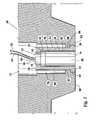
- FIG. 2provides a cross-sectional side view of an end plug for the ultrasonic cement analyzer having the inventive shear wave transducer mounted therein showing the acoustic element and isolator in greater detail.
- FIG. 1A typical end plug 10 for an ultrasonic cement analyzer (“UCA”) is shown in FIG. 1 .
- end plug 10has transducer 12 mounted therein such that a contacting surface 14 of transducer 12 can contact a cement sample contained in a UCA cell (not shown) to be capped with end plug 10 .
- surface 14may protrude slightly below bottom surface 60 and end 22 to improve contact with the sample.
- transducer 12includes: transmitter 13 , body 38 , and acoustic couplant 45 .
- Delay line 15includes isolator 16 ; and acoustic element 18 .
- Isolator 16is essentially cylindrical in appearance having: flange 20 extending radially outward from end 22 ; an exterior side wall 24 extending upward from flange 20 to distal end 26 ; cylindrical cavity 28 formed by interior wall 30 ; and top wall 32 having aperture 34 opening into cavity 28 .
- Ultrasonic transmitter 13is preferably a commercially available transducer.
- One such ultrasonic transduceris the Harisonic transducer used with prior art UCA devices.
- transmitter 13includes: a body 42 and an electrical connector 44 for receiving electrical pulses to excite transmitter 13 .
- connector 44is a BNC-type connector.
- acoustic element 18is typically a unitary structure formed from metal, or other rigid material, and includes: a cylindrical top end 36 ; a cylindrical body portion 38 ; a flange 40 separating end 36 from body 38 .
- Transducer 12is assembled by pressing top end 36 in to aperture 34 until flange 40 contacts top wall 32 .
- cavity 28has a diameter somewhat larger than the diameter of body 38 so that a gap 46 is formed between body portion 38 and interior wall 30 .
- Acoustic energyis coupled from transmitter 13 to acoustic element 18 through acoustic couplant 45 .
- end plug 10includes a bottom surface 60 having cavity 62 therein.
- Cavity 62is generally a series of coaxial cylindrical cavities of varying diameter giving cavity 62 a “stepped” appearance.
- cavity 62has a lower cylindrical cavity 64 which is preferably sized to receive flange 20 of isolator 16 .
- Flange 66is defined by a second cylindrical cavity 68 having a smaller diameter than that of cavity 64 .
- a third cavity 69is formed of a larger diameter than that of body 38 creating a cylindrical gap 70 and, finally, an upper cavity 72 is formed, preferably extending to the top surface (not shown) of end plug 10 .
- transducer 12When transducer 12 is installed in end plug 10 , housing 16 is inserted into cavity 62 until flange 20 contacts flange 66 . Transmitter 13 is placed above body 38 and held in place with sleeve 100 and snap ring 102 placed in snap ring groove 104 near the upper end of cavity 72 . Wave spring 110 maintains pressure between transmitter 13 and acoustic couplant 45 and body 38 . As will be apparent to those skilled in the art, body 38 is thus only supported at its lower end. When a pulse is applied to transmitter 13 , acoustic element 18 is driven in its axial direction which will generate a compressional wave in a cement sample in contact with end 14 .
- an electrical pulse applied to transmitter 13will also result in lateral movement of acoustic element 18 .
- transmitter 13was pressed directly into end plug 10 at surface 60 .
- the mass of end plug 10 and the rigid mounting of transmitter 13 near the samplegreatly limited the generation of a shear wave in the sample.
- the mass of the end plug 10is, to a large degree, isolated from transducer 12 since isolator 16 is secured at its lower end and acoustic element 18 is secured at its upper end.
- Gaps 46 and 70reduce the degree to which end plug 10 attenuates lateral movement of acoustic element 18 .
- the amplitude of the shear wave produced by the inventive transducer 12will be many times greater than would be produced if transmitter 13 were simply mounted directly in end plug 10 .
- the transducermay be forced into contact with the sample by a piston 112 ( FIG. 1 ).
- piston 112acts on the sleeve 100 to compress the wave spring 110 , and force transmitter 13 , isolator 16 , and transducer 12 to move so that transducer 12 is forced into contact with a sample.
- piston 112is shown in FIG. 1 as an example, other force applying devices may be used. Further piston 112 may be located elsewhere to impart force to transducer 12 .
- piston 112may be keyed to end plug 10 and act directly on isolator 16 or may be configured in other ways.
- the shear wavewill arrive at a receiver later than the compressional wave.
- a time based methodmay be used to distinguish between the two waves.
- a second end plugcapping the opposite end of the UCA cell, may be configured to house an ultrasonic receiver.
- the first ultrasonic pulse receivedwill indicate the arrival of the compressional wave.
- the velocity of the wavemay simply be calculated by dividing the distance between the receiver and transmitter by the elapsed time between transmittal of the pulse and its arrival at the receiver.
- the second ultrasonic pulse receivedwill be as a result of the shear wave.
- the shear wave velocityis likewise calculated by dividing the distance between the transmitter and receiver by the time period between excitation of the transmitter and the and receipt of the second pulse.
- the shear waveat a frequency different from that of the compressional wave which allows the two waves to be measured independently through filtering of the received signal. Since the shear wave velocity in steel is typically half the speed of the compressional wave velocity, the shear wave frequency generated by the inventive transducer 12 will be approximately half the frequency of the compressional wave. As will be apparent to those skilled in the art, after the compressional and shear wave are received, the two waves may be separated with relatively simple electrical filtering.
- a cement samplemay be tested at elevated pressures and temperatures which actually simulate those encountered in casing an oil or gas well.
- the setting timemay be determined from the point in time at which a shear wave will propagate through the sample
- the compressive strengthmay be determined from the velocity of the compressional wave as the cement sets
- the dynamic mechanical propertiesi.e., Poisson's ratio and Young's modulus
Landscapes
- Chemical & Material Sciences (AREA)
- Physics & Mathematics (AREA)
- Health & Medical Sciences (AREA)
- Life Sciences & Earth Sciences (AREA)
- Analytical Chemistry (AREA)
- Engineering & Computer Science (AREA)
- Biochemistry (AREA)
- General Health & Medical Sciences (AREA)
- General Physics & Mathematics (AREA)
- Immunology (AREA)
- Pathology (AREA)
- Food Science & Technology (AREA)
- Medicinal Chemistry (AREA)
- Ceramic Engineering (AREA)
- Acoustics & Sound (AREA)
- Investigating Or Analyzing Materials By The Use Of Ultrasonic Waves (AREA)
Abstract
Description
This application claims the benefit of U.S. Provisional Application No. 60/325,611, which application was filed with the Patent and Trademark Office on Sep. 28, 2001.
1. Field of the Invention
The present invention relates to a transducer for simultaneously producing compressional and shear waves in a cement sample. More particularly, but not by way of limitation, the present invention relates to a transducer which allows the measurement of the shear wave velocity and compressional wave velocity in a universal cement analyzer cell so as to determine dynamic mechanical properties, i.e., Poisson's ratio and Young's modulus, as well as other properties of a cement sample.
2. Background of the Invention
Ultrasonic cement analyzers (“UCA”) are well known in the art. Compressive strength measurements of a cement sample are best taken using such a device. While the UCA provides a number of advantages over alternative methods for measuring, or estimating, the characteristics of a particular cement sample, a compelling advantage is the ability of the UCA to perform nondestructive measurements. Thus, a single sample may be used to perform a series of measurements, whereas, with alternative methods, a series of samples are required for each measurement to be made. Using a single sample reduces cost, provides more consistent testing, reduces record keeping, saves time, etc.
The UCA was developed to measure the compressive strength of a cement slurry as it sets when subjected to simulated oil field temperatures and pressures. It consists of a high temperature-high pressure autoclave, a heat jacket capable of heating rates up to 5.6.degree. C. (10.degree. F.) per minute, a pair of 400 kHz ultrasonic transducers for measuring the transit time of an acoustic signal transmitted through the slurry, plus associated hydraulic plumbing. The two transducers make transit time measurements through the cement as it sets. A short pulse on a lower transducer propagates through the cement to an upper transducer. Set time and compressive strength are calculated from measured transit time via empirically developed equations. U.S. Pat. Nos. 4,259,868 and 4,567,765 disclose the UCA in detail and are incorporated herein by reference.
It is also known in the art that an acoustic shear wave may be used to determine the setting time of cement. In one method for using a shear wave to determine setting time, a shear wave is generated at a location in a cement slurry. The point in time at which the shear wave propagates through the slurry is indicative of the setting time of the cement. U.S. Pat. No. 5,412,990 issued to D'Angelo et al. discloses such a method for measuring cement thickening time using a shear wave and is hereby incorporated by reference.
In addition, if both the shear wave velocity and compressional wave velocity are known, it is possible to calculate various dynamic mechanical properties of the sample such as Poisson's ratio, Young's modulus, etc. Poisson's ratio is defined as the absolute value of the ratio of transverse strain to the corresponding axial strain resulting from uniformly distributed axial stress below the proportional limit of the material. Young's modulus is the elastic modulus in tension or compression. This information if useful for material development or characterization as well as for quality control purposes. While wave velocities have been employed for the measurement of dynamic mechanical properties in rock specimens, they have not heretofore been used to determine such properties in a cement sample.
An additional disadvantage associated with traditional UCA devices is that, historically, all acoustic cement tests have been run with the cell oriented vertically. With some cement samples, a layer of low strength material forms at the top, which can cause a limitation in the transfer of acoustic energy from the cell/transducer, to the cement at the send end. Further, the low strength material can cause a limitation in the transfer of acoustic energy from the cement to the cell/transducer at the receiving end.
It is thus an object of the present invention to provide a transducer which may be used to simultaneously produce shear and compressional waves in a cement sample.
It is yet a further object of the present invention to provide an ultrasonic cement analyzer which will measure shear wave and compressional wave velocities.
It is still a further object of the present invention to provide a method for measuring the velocities of the shear and compressional waves produced in a sample and to indicate the dynamic mechanical properties of the sample.
It is a further object of the present invention to provide an apparatus and method for overcoming limitations in a transfer of acoustic energy from the cell/transducer to the cement and vise versa due to low strength material adjacent the transducer.
The present invention provides a transducer which will simultaneously produce shear and compressional waves in a sample and a method for using the measured velocities of the shear and compressional waves to determine dynamic mechanical properties of the sample such as Poisson's ratio.
In a preferred embodiment, an ultrasonic transducer is mounted in an end plug for a standard UCA cell. The transducer is in acoustic communication with an acoustic element mounted in an isolator such that acoustic element is free to move laterally for production of the shear wave. When an electrical pulse is applied to the transducer, an acoustic pulse travels axially down the acoustic element and into the cement sample as a compressional wave. In addition, the acoustic element moves laterally in response to the electrical pulse to also produce a shear wave in the sample. The internal portion of the inventive acoustic element is secured to the isolator at the end furthest from the cement sample thereby allowing greater freedom of movement in the lateral direction than has heretofore been possible.
In another embodiment, the velocities of the compressional wave and shear wave produced by the inventive transducer are measured to determine the dynamic mechanical properties, for example Poisson's ratio and Young's modulus, of the sample under test.
In addition, the UCA may also provide all of the features and perform all of the functions of a conventional UCA. Thus, an UCA incorporating the present invention provides a convenient method to measure the change in mechanical properties of a cement sample at elevated temperatures and pressures as the sample transitions from a slurry, through gelation, to a solid, as setting occurs.
In one embodiment, the transmission and reception of acoustic energy is improved by orienting the transducers and sample in a horizontal configuration. In a horizontal orientation, the cement sample in contact with the centralized transducer is an average of the cement in the cell. If a weak “punky” layer of cement then forms at or near the top of the cement sample, the weak layer will be adjacent a wall of the sample cylinder rather than adjacent a transducer.
Other benefits of a horizontal orientation are observable when testing “foamed” cements that have a meaningful percentage of entrained gas, e.g., 10% to 40% entrained gas, although other percentages are also contemplated to be used with the invention. As the cement is pressurized, the gas bubble become smaller. Therefore, a gap can form between the cement and the cell/transducer. The gap can be large enough that tests cannot be run. However, when placed in a horizontal orientation, the cement sample volume can change substantially before the acoustic analysis is seriously affected.
In another embodiment, the transmission and reception of acoustic energy is improved by forcing the transducer into contact with the sample with a piston or other force applying device.
Further objects, features, and advantages of the present invention will be apparent to those skilled in the art upon examining the accompanying drawings and upon reading the following description of the preferred embodiments.
Before explaining the present invention in detail, it is important to understand that the invention is not limited in its application to the details of the construction illustrated and the steps described herein. The invention is capable of other embodiments and of being practiced or carried out in a variety of ways. It is to be understood that the phraseology and terminology employed herein is for the purpose of description and not of limitation.
Atypical end plug 10 for an ultrasonic cement analyzer (“UCA”) is shown inFIG. 1 . Preferably, end plug10 hastransducer 12 mounted therein such that a contactingsurface 14 oftransducer 12 can contact a cement sample contained in a UCA cell (not shown) to be capped withend plug 10. It should be noted thatsurface 14 may protrude slightly belowbottom surface 60 and end22 to improve contact with the sample.
Preferably,transducer 12 includes:transmitter 13,body 38, andacoustic couplant 45. Delay line15 includesisolator 16; andacoustic element 18.Isolator 16 is essentially cylindrical in appearance having: flange20 extending radially outward fromend 22; anexterior side wall 24 extending upward fromflange 20 todistal end 26;cylindrical cavity 28 formed byinterior wall 30; andtop wall 32 havingaperture 34 opening intocavity 28.
Referring now toFIGS. 1 and 2 ,acoustic element 18 is typically a unitary structure formed from metal, or other rigid material, and includes: a cylindricaltop end 36; acylindrical body portion 38; aflange 40 separatingend 36 frombody 38.
Preferably, end plug10 includes abottom surface 60 havingcavity 62 therein.Cavity 62 is generally a series of coaxial cylindrical cavities of varying diameter giving cavity62 a “stepped” appearance. In a preferred embodiment,cavity 62 has a lowercylindrical cavity 64 which is preferably sized to receiveflange 20 ofisolator 16.Flange 66 is defined by a secondcylindrical cavity 68 having a smaller diameter than that ofcavity 64. Aboveflange 66, athird cavity 69 is formed of a larger diameter than that ofbody 38 creating acylindrical gap 70 and, finally, anupper cavity 72 is formed, preferably extending to the top surface (not shown) ofend plug 10.
Whentransducer 12 is installed inend plug 10,housing 16 is inserted intocavity 62 untilflange 20contacts flange 66.Transmitter 13 is placed abovebody 38 and held in place withsleeve 100 and snap ring102 placed insnap ring groove 104 near the upper end ofcavity 72.Wave spring 110 maintains pressure betweentransmitter 13 and acoustic couplant45 andbody 38. As will be apparent to those skilled in the art,body 38 is thus only supported at its lower end. When a pulse is applied totransmitter 13,acoustic element 18 is driven in its axial direction which will generate a compressional wave in a cement sample in contact withend 14. In addition, an electrical pulse applied totransmitter 13 will also result in lateral movement ofacoustic element 18. In prior art designs,transmitter 13 was pressed directly intoend plug 10 atsurface 60. The mass ofend plug 10 and the rigid mounting oftransmitter 13 near the sample greatly limited the generation of a shear wave in the sample. In contrast, in the inventive transducer, the mass of theend plug 10 is, to a large degree, isolated fromtransducer 12 sinceisolator 16 is secured at its lower end andacoustic element 18 is secured at its upper end.Gaps acoustic element 18. Thus, the amplitude of the shear wave produced by theinventive transducer 12 will be many times greater than would be produced iftransmitter 13 were simply mounted directly inend plug 10.
To further improve the transmission and reception of acoustic energy, the transducer may be forced into contact with the sample by a piston112 (FIG. 1 ). As shown inFIG. 1 ,piston 112 acts on thesleeve 100 to compress thewave spring 110, and forcetransmitter 13,isolator 16, andtransducer 12 to move so thattransducer 12 is forced into contact with a sample. Althoughpiston 112 is shown inFIG. 1 as an example, other force applying devices may be used.Further piston 112 may be located elsewhere to impart force totransducer 12. For example,piston 112 may be keyed to endplug 10 and act directly onisolator 16 or may be configured in other ways.
As will be apparent to those skilled in the art, to determine the velocities of the compressional wave and shear wave independently, there must be some method for distinguishing each wave independently at a receiver. Two techniques are possible with the inventive apparatus.
First, in a typical sample, the shear wave will arrive at a receiver later than the compressional wave. Thus, a time based method may be used to distinguish between the two waves. Those familiar with cement analyzers will appreciate that, typically, a second end plug, capping the opposite end of the UCA cell, may be configured to house an ultrasonic receiver. After the generation of the waves in the sample, the first ultrasonic pulse received will indicate the arrival of the compressional wave. The velocity of the wave may simply be calculated by dividing the distance between the receiver and transmitter by the elapsed time between transmittal of the pulse and its arrival at the receiver. The second ultrasonic pulse received will be as a result of the shear wave. The shear wave velocity is likewise calculated by dividing the distance between the transmitter and receiver by the time period between excitation of the transmitter and the and receipt of the second pulse.
Alternatively, it is also possible to generate the shear wave at a frequency different from that of the compressional wave which allows the two waves to be measured independently through filtering of the received signal. Since the shear wave velocity in steel is typically half the speed of the compressional wave velocity, the shear wave frequency generated by theinventive transducer 12 will be approximately half the frequency of the compressional wave. As will be apparent to those skilled in the art, after the compressional and shear wave are received, the two waves may be separated with relatively simple electrical filtering.
The importance in measuring the velocities of the shear wave and compressional wave is that, when such values are known, it is possible to calculate dynamic mechanical properties of the sample such as, for example, Poisson's ratio and Young's modulus. As will be apparent to those skilled in the art, known relationships have been demonstrated between the compressional and shear wave velocities and various mechanical properties of specific materials.
For example, it has previously been shown that Poisson's ratio and Young's modulus for a rock specimen may be determined if the acoustical compressional and shear wave velocities are known for that specimen. In such a specimen, Young's modulus (E) is given by:
E=CS2ρ[3(CP/CS)2−4]/(CP/CS)2−1]
E=CS2ρ[3(CP/CS)2−4]/(CP/CS)2−1]
- where:
- CSis the velocity of the shear wave through the specimen;
- CPis the velocity of the compressional wave through the specimen; and
- ρ is the density of the material.
- where:
Poisson's ratio (μ) is given by:
μ=½[(CP/CS)2−2]/[(CP/CS)2−1]
μ=½[(CP/CS)2−2]/[(CP/CS)2−1]
As will be apparent to those skilled in the art, the above equations may vary somewhat depending on the particular geometry of the specimen measured, however it is within the skill level of one of ordinary skill in the art to empirically determine such modifications. Likewise, while these equations would provide a good estimate for Young's modulus and Poisson's ratio for a cement sample tested in a UCA, modifying the equations to account for the particular geometry of the UCA test cell and differences between a rock specimen and a cement specimen could improve the accuracy of the calculation. Again, it is within the skill level of one of ordinary skill in the art to empirically determine such modifications.
It should thus be noted that, when using an UCA employing a shear transducer, such as the inventive shear transducer, a cement sample may be tested at elevated pressures and temperatures which actually simulate those encountered in casing an oil or gas well. In addition, as an individual sample sets, it is possible to determine a number of mechanical properties of the sample as the cement transitions from a slurry, through the gelation stage, and into a solid. As discussed above, the setting time may be determined from the point in time at which a shear wave will propagate through the sample, the compressive strength may be determined from the velocity of the compressional wave as the cement sets, and the dynamic mechanical properties (i.e., Poisson's ratio and Young's modulus) may be determined from the velocities of the shear and compressional waves as the cement transitions into the solid state. In such a UCA, it is possible to measure, display, and record changes in the mechanical properties of the sample as setting occurs.
In an additional embodiment of the invention, further improvement to the UCA process can be achieved by orienting the transducer, receiver and sample horizontally rather than vertically.
Thus, the present invention is well adapted to carry out the objects and attain the ends and advantages mentioned above as well as those inherent therein. While presently preferred embodiments have been described for purposes of this disclosure, numerous changes and modifications will be apparent to those skilled in the art. Such changes and modifications are encompassed within the spirit of this invention.
Claims (16)
1. An apparatus for determining the dynamic mechanical properties of a cement sample comprising:
an end plug adapted for use with an ultrasonic cement analyzer;
a horizontally mounted transducer within a cavity in said end plug, said transducer having an attached end and a free end;
wherein said transducer is supported on only said attached end, thereby permitting said free end to move laterally for generating a shear wave.
2. An apparatus for determining the dynamic mechanical properties of a cement sample comprising:
a body defining a cavity, said cavity having a wide end and a narrow end;
an isolator within said cavity, said isolator having an attached end and a distal end and having an internal wall that defines an interior space, said attached end engaging said body proximate said narrow end of said cavity;
a transducer having an attached end and a free end, said transducer in said interior space of said isolator, said attached end of said transducer engaging said isolator proximate said distal end of said isolator; and
wherein said transducer is capable of generating a compressive wave that travels into the sample and said transducer is also capable of generating a shear wave that travels into the sample.
3. The apparatus according toclaim 2 wherein:
said cavity of said body and an exterior wall of said isolator define a space therebetween, said space for facilitating lateral movement of said distal end of said isolator.
4. The apparatus according toclaim 2 wherein:
said internal wall of said isolator and a body portion of said transducer define a space therebetween, said space for facilitating lateral movement of said distal end of said transducer.
5. The apparatus according toclaim 2 further comprising:
an ultrasonic receiver housed in a second body at an opposite end of the sample for receiving said compressive wave and said shear wave.
6. The apparatus according toclaim 2 wherein:
said body, isolator and transducer are oriented vertically.
7. The apparatus according toclaim 2 further comprising:
a force applicator in communication with said transducer, for forcing said transducer into contact with the sample.
8. The apparatus according toclaim 1 further comprising:
a transmitter having a first end and a second end, said second end in communication with said distal end of said isolator.
9. The apparatus according toclaim 8 further comprising:
an acoustic couplant having a first end and a second end, said first end in communication with said second end of said transmitter, said second end of said acoustic couplant in communication with said distal end of said isolator.
10. The apparatus according toclaim 9 further comprising:
a sleeve in said cavity of said body, said sleeve having a contacting end;
a wave spring having a first side and a second side, said first side in communication with said contacting end of said sleeve and said second side in communication with said first end of said transmitter; and
wherein said wave spring maintains pressure between said transmitter and said acoustic couplant.
11. A method for determining dynamic mechanical properties of a cement sample comprising the steps of:
generating a compressive wave and a shear wave with a transducer;
propagating said compressive wave and said shear wave into the sample;
receiving said compressive wave and said shear wave with an ultrasonic receiver; and
separating said compressive wave and said shear wave with electrical filtering.
12. The method according toclaim 11 further comprising the step of:
determining setting time of the sample from a point in time at which said shear wave will propagate through the sample.
13. The method according toclaim 11 further comprising the step of:
determining compressive strength of the sample from velocity of the compressive wave as the sample sets.
14. The method according toclaim 11 wherein:
dynamic mechanical properties may be determined from velocities of said shear wave and said compressive wave as the sample transitions into a solid state.
15. The method according toclaim 11 wherein:
said step of propagating is conducted as the sample is in a state selected from a group consisting of a slurry, a gelation stage, a solid, a transition from a slurry to a gelation phase and a transition from a gelation stage into a solid.
16. The method according toclaim 11 further comprising the step of:
forcing said transducer into contact with the sample.
Priority Applications (1)
| Application Number | Priority Date | Filing Date | Title |
|---|---|---|---|
| US10/260,707US6941819B1 (en) | 2001-09-28 | 2002-09-30 | Apparatus and method for determining the dynamic mechanical properties of a cement sample |
Applications Claiming Priority (2)
| Application Number | Priority Date | Filing Date | Title |
|---|---|---|---|
| US32561101P | 2001-09-28 | 2001-09-28 | |
| US10/260,707US6941819B1 (en) | 2001-09-28 | 2002-09-30 | Apparatus and method for determining the dynamic mechanical properties of a cement sample |
Publications (1)
| Publication Number | Publication Date |
|---|---|
| US6941819B1true US6941819B1 (en) | 2005-09-13 |
Family
ID=34915330
Family Applications (1)
| Application Number | Title | Priority Date | Filing Date |
|---|---|---|---|
| US10/260,707Expired - LifetimeUS6941819B1 (en) | 2001-09-28 | 2002-09-30 | Apparatus and method for determining the dynamic mechanical properties of a cement sample |
Country Status (1)
| Country | Link |
|---|---|
| US (1) | US6941819B1 (en) |
Cited By (19)
| Publication number | Priority date | Publication date | Assignee | Title |
|---|---|---|---|---|
| US20060278024A1 (en)* | 2003-12-12 | 2006-12-14 | Bj Services Company | Testing apparatus and method of deriving young's modulus from tensile stress/strain relationships |
| US20080112262A1 (en)* | 2006-11-15 | 2008-05-15 | Baker Hughes Incorporated | Cement bond analysis |
| US20080148852A1 (en)* | 2006-12-20 | 2008-06-26 | Maki Voldi E | Acoustic transducer system for nondestructive testing of cement |
| US20090205427A1 (en)* | 2005-04-20 | 2009-08-20 | Sika Technology Ag | Device and Method for Determining the Dynamic Elastic Modulus of a Material |
| US20100042342A1 (en)* | 2008-08-14 | 2010-02-18 | Maki Jr Voldi E | Method and Apparatus for Measurement of Mechanical Characteristics of a Cement Sample |
| US20100087827A1 (en)* | 2007-03-30 | 2010-04-08 | Gamal Baroud | Method and apparatus for monitoring and/or controlling the curing of cements used in medical procedures |
| CN101852705A (en)* | 2010-06-18 | 2010-10-06 | 南京理工大学 | Evaluation method for dynamic damage of materials under multiple impacts |
| US20120235692A1 (en)* | 2008-04-21 | 2012-09-20 | Enerize, Inc. | Method and device for rapid non-destructive quality control of powdered materials |
| CN103544549A (en)* | 2013-11-05 | 2014-01-29 | 江苏博特新材料有限公司 | Predication method of cement asphalt mortar elasticity modulus |
| US20150033862A1 (en)* | 2012-02-22 | 2015-02-05 | Total Sa | Method for characterising the mechanical behaviour of cements |
| US20150068292A1 (en)* | 2012-04-12 | 2015-03-12 | Total Sa | Method for determining geomechanical parameters of a rock sample |
| US20160139086A1 (en)* | 2012-12-12 | 2016-05-19 | Aktiebolaget Skf | Couplant and arrangement of couplant, transducer, and construction component |
| CN106383050A (en)* | 2016-08-26 | 2017-02-08 | 四川省建筑科学研究院 | Detection method for detecting brickwork shear strength of cement mortar concrete porous brick wall |
| US20170176398A1 (en)* | 2014-05-28 | 2017-06-22 | Aktiebolaget Skf | Couplant and arrangement of couplant, transducer, and construction component |
| US20190011405A1 (en)* | 2016-01-18 | 2019-01-10 | British Columbia Institute Of Technology | Method and Apparatus for Non-Destructive Measurement of Modulus of Elasticity and/or the Compressive Strength of Masonry Samples |
| WO2021081529A1 (en)* | 2019-10-25 | 2021-04-29 | Conocophillips Company | Systems and methods for analyzing casing bonding in a well using ultrasound velocity filtering |
| CN117890477A (en)* | 2024-03-13 | 2024-04-16 | 西南交通大学 | Method for calculating compressive strength of rock based on TSP data |
| JP7590940B2 (en) | 2021-08-06 | 2024-11-27 | 株式会社熊谷組 | Method and device for estimating time to strength development of concrete |
| US12247952B2 (en) | 2021-10-21 | 2025-03-11 | Council Of Scientific And Industrial Research | Ultrasonic pulse velocity tester device with threshold error correction |
Citations (36)
| Publication number | Priority date | Publication date | Assignee | Title |
|---|---|---|---|---|
| US2833142A (en) | 1955-02-15 | 1958-05-06 | Ernest M Runquist | Ultrasonic, high pressure interferometer |
| US3641811A (en) | 1969-12-02 | 1972-02-15 | Robert J Gnaedinger Jr | Method and apparatus for determining structural characteristics |
| US4073193A (en)* | 1976-10-04 | 1978-02-14 | Mastandrea John R | Transducer device |
| US4254479A (en)* | 1979-03-22 | 1981-03-03 | Phillips Petroleum Company | Sonic logging method for determining the need for sand consolidation treatment |
| US4259868A (en) | 1979-10-01 | 1981-04-07 | Halliburton Company | Method and apparatus for nondestructive testing of cement |
| US4265120A (en) | 1979-05-23 | 1981-05-05 | Rockwell International Corporation | Fatigue detection utilizing acoustic harmonics |
| US4377087A (en) | 1979-10-11 | 1983-03-22 | Societe Nationale Elf Aquitaine (Production) | Device for acoustically controlling the setting and hardening characteristics of cements |
| US4380930A (en)* | 1981-05-01 | 1983-04-26 | Mobil Oil Corporation | System for transmitting ultrasonic energy through core samples |
| US4567765A (en) | 1984-07-05 | 1986-02-04 | Halliburton Company | High pressure-high temperature autoclave system for testing fluid samples ultrasonically |
| US4622846A (en) | 1985-11-05 | 1986-11-18 | Halliburton Company | Consistency and static gel strength measuring device and method |
| US4625542A (en)* | 1984-09-14 | 1986-12-02 | Tab Leasing | Radiation power measuring apparatus |
| US4649750A (en) | 1985-09-13 | 1987-03-17 | The United States Of America As Represented By The Administrator Of The National Aeronautics And Space Administration | Acoustic radiation stress measurement |
| US4655084A (en) | 1985-06-03 | 1987-04-07 | Krautkramer-Branson, Inc. | Ultrasonic test instrument |
| US4754645A (en) | 1987-05-14 | 1988-07-05 | Canadian Patents And Development Limited | Ultrasonic characterization of polymers under simulated processing conditions |
| US4843598A (en)* | 1988-05-03 | 1989-06-27 | Mobil Oil Corporation | Method of shear wave porosity logging of a subsurface formation surrounding a cased well |
| US4862384A (en) | 1987-08-03 | 1989-08-29 | Rockwell International Corporation | Method of measuring the dynamic viscosity of a viscous fluid utilizing acoustic transducer |
| US5001676A (en)* | 1990-04-27 | 1991-03-19 | Mobil Oil Corporation | Acoustic borehole logging |
| US5009102A (en) | 1988-01-22 | 1991-04-23 | Board Of Regents Of The University Of Washington | Method of monitoring solidification of a liquid composition |
| US5089989A (en)* | 1989-06-12 | 1992-02-18 | Western Atlas International, Inc. | Method and apparatus for measuring the quality of a cement to a casing bond |
| US5092176A (en) | 1990-06-29 | 1992-03-03 | The Babcock & Wilcox Company | Method for determining deposit buildup |
| US5099849A (en) | 1988-05-11 | 1992-03-31 | Lunar Corporation | Ultrasonic densitometer device and method |
| US5119820A (en) | 1988-05-11 | 1992-06-09 | Lunar Corporation | Ultrasonic densitometer device and method |
| EP0577511A1 (en) | 1992-07-03 | 1994-01-05 | Bongrain S.A. | Device and method for the detection of changes of phase of a product |
| US5412990A (en) | 1992-03-20 | 1995-05-09 | Schlumberger Technology Corporation | Method for measuring cement thickening times |
| US5433112A (en) | 1992-09-15 | 1995-07-18 | Piche; Luc | Ultrasonic characterization of polymer melts under processing conditions |
| US5625140A (en)* | 1995-12-12 | 1997-04-29 | Lucent Technologies Inc. | Acoustic analysis of gas mixtures |
| DE19626111C1 (en) | 1996-06-28 | 1997-10-02 | Max Prof Dr Rer Nat Dr Setzer | Freezing and defrosting resistance testing method for sample slab |
| US5741971A (en) | 1996-01-17 | 1998-04-21 | Bj Services Company | Method for analyzing physical properties of materials |
| US5763773A (en)* | 1996-09-20 | 1998-06-09 | Halliburton Energy Services, Inc. | Rotating multi-parameter bond tool |
| US5846462A (en) | 1997-05-16 | 1998-12-08 | Thompson; Edward J. | Method and apparatus for making high compression structural foam |
| US5853475A (en) | 1994-05-20 | 1998-12-29 | New Jersey Institute Of Technology | Compressive strength of concrete and mortar containing fly ash |
| US5992223A (en) | 1997-07-14 | 1999-11-30 | Chandler Engineering Company Llc | Acoustic method for determining the static gel strength of a cement slurry |
| US6070465A (en)* | 1998-08-24 | 2000-06-06 | Dresser Industries | Free water measurement apparatus and method thereof |
| US6112599A (en)* | 1998-03-26 | 2000-09-05 | Cement Test Equipment, Inc. | Method and apparatus for measuring a cement sample using a single transducer assembly |
| US6345535B1 (en) | 2000-06-17 | 2002-02-12 | Chandler Engineering Company Llc | Apparatus and method for estimating the compressive strength of foam cement |
| US6483777B1 (en)* | 1998-01-06 | 2002-11-19 | Schlumberger Technology Corporation | Method and apparatus for ultrasonic imaging of a cased well |
- 2002
- 2002-09-30USUS10/260,707patent/US6941819B1/ennot_activeExpired - Lifetime
Patent Citations (36)
| Publication number | Priority date | Publication date | Assignee | Title |
|---|---|---|---|---|
| US2833142A (en) | 1955-02-15 | 1958-05-06 | Ernest M Runquist | Ultrasonic, high pressure interferometer |
| US3641811A (en) | 1969-12-02 | 1972-02-15 | Robert J Gnaedinger Jr | Method and apparatus for determining structural characteristics |
| US4073193A (en)* | 1976-10-04 | 1978-02-14 | Mastandrea John R | Transducer device |
| US4254479A (en)* | 1979-03-22 | 1981-03-03 | Phillips Petroleum Company | Sonic logging method for determining the need for sand consolidation treatment |
| US4265120A (en) | 1979-05-23 | 1981-05-05 | Rockwell International Corporation | Fatigue detection utilizing acoustic harmonics |
| US4259868A (en) | 1979-10-01 | 1981-04-07 | Halliburton Company | Method and apparatus for nondestructive testing of cement |
| US4377087A (en) | 1979-10-11 | 1983-03-22 | Societe Nationale Elf Aquitaine (Production) | Device for acoustically controlling the setting and hardening characteristics of cements |
| US4380930A (en)* | 1981-05-01 | 1983-04-26 | Mobil Oil Corporation | System for transmitting ultrasonic energy through core samples |
| US4567765A (en) | 1984-07-05 | 1986-02-04 | Halliburton Company | High pressure-high temperature autoclave system for testing fluid samples ultrasonically |
| US4625542A (en)* | 1984-09-14 | 1986-12-02 | Tab Leasing | Radiation power measuring apparatus |
| US4655084A (en) | 1985-06-03 | 1987-04-07 | Krautkramer-Branson, Inc. | Ultrasonic test instrument |
| US4649750A (en) | 1985-09-13 | 1987-03-17 | The United States Of America As Represented By The Administrator Of The National Aeronautics And Space Administration | Acoustic radiation stress measurement |
| US4622846A (en) | 1985-11-05 | 1986-11-18 | Halliburton Company | Consistency and static gel strength measuring device and method |
| US4754645A (en) | 1987-05-14 | 1988-07-05 | Canadian Patents And Development Limited | Ultrasonic characterization of polymers under simulated processing conditions |
| US4862384A (en) | 1987-08-03 | 1989-08-29 | Rockwell International Corporation | Method of measuring the dynamic viscosity of a viscous fluid utilizing acoustic transducer |
| US5009102A (en) | 1988-01-22 | 1991-04-23 | Board Of Regents Of The University Of Washington | Method of monitoring solidification of a liquid composition |
| US4843598A (en)* | 1988-05-03 | 1989-06-27 | Mobil Oil Corporation | Method of shear wave porosity logging of a subsurface formation surrounding a cased well |
| US5119820A (en) | 1988-05-11 | 1992-06-09 | Lunar Corporation | Ultrasonic densitometer device and method |
| US5099849A (en) | 1988-05-11 | 1992-03-31 | Lunar Corporation | Ultrasonic densitometer device and method |
| US5089989A (en)* | 1989-06-12 | 1992-02-18 | Western Atlas International, Inc. | Method and apparatus for measuring the quality of a cement to a casing bond |
| US5001676A (en)* | 1990-04-27 | 1991-03-19 | Mobil Oil Corporation | Acoustic borehole logging |
| US5092176A (en) | 1990-06-29 | 1992-03-03 | The Babcock & Wilcox Company | Method for determining deposit buildup |
| US5412990A (en) | 1992-03-20 | 1995-05-09 | Schlumberger Technology Corporation | Method for measuring cement thickening times |
| EP0577511A1 (en) | 1992-07-03 | 1994-01-05 | Bongrain S.A. | Device and method for the detection of changes of phase of a product |
| US5433112A (en) | 1992-09-15 | 1995-07-18 | Piche; Luc | Ultrasonic characterization of polymer melts under processing conditions |
| US5853475A (en) | 1994-05-20 | 1998-12-29 | New Jersey Institute Of Technology | Compressive strength of concrete and mortar containing fly ash |
| US5625140A (en)* | 1995-12-12 | 1997-04-29 | Lucent Technologies Inc. | Acoustic analysis of gas mixtures |
| US5741971A (en) | 1996-01-17 | 1998-04-21 | Bj Services Company | Method for analyzing physical properties of materials |
| DE19626111C1 (en) | 1996-06-28 | 1997-10-02 | Max Prof Dr Rer Nat Dr Setzer | Freezing and defrosting resistance testing method for sample slab |
| US5763773A (en)* | 1996-09-20 | 1998-06-09 | Halliburton Energy Services, Inc. | Rotating multi-parameter bond tool |
| US5846462A (en) | 1997-05-16 | 1998-12-08 | Thompson; Edward J. | Method and apparatus for making high compression structural foam |
| US5992223A (en) | 1997-07-14 | 1999-11-30 | Chandler Engineering Company Llc | Acoustic method for determining the static gel strength of a cement slurry |
| US6483777B1 (en)* | 1998-01-06 | 2002-11-19 | Schlumberger Technology Corporation | Method and apparatus for ultrasonic imaging of a cased well |
| US6112599A (en)* | 1998-03-26 | 2000-09-05 | Cement Test Equipment, Inc. | Method and apparatus for measuring a cement sample using a single transducer assembly |
| US6070465A (en)* | 1998-08-24 | 2000-06-06 | Dresser Industries | Free water measurement apparatus and method thereof |
| US6345535B1 (en) | 2000-06-17 | 2002-02-12 | Chandler Engineering Company Llc | Apparatus and method for estimating the compressive strength of foam cement |
Cited By (38)
| Publication number | Priority date | Publication date | Assignee | Title |
|---|---|---|---|---|
| US20060278024A1 (en)* | 2003-12-12 | 2006-12-14 | Bj Services Company | Testing apparatus and method of deriving young's modulus from tensile stress/strain relationships |
| US20090205427A1 (en)* | 2005-04-20 | 2009-08-20 | Sika Technology Ag | Device and Method for Determining the Dynamic Elastic Modulus of a Material |
| US8215172B2 (en)* | 2005-04-20 | 2012-07-10 | Sika Technology Ag | Device and method for determining the dynamic elastic modulus of a material |
| US20080112262A1 (en)* | 2006-11-15 | 2008-05-15 | Baker Hughes Incorporated | Cement bond analysis |
| US7787327B2 (en)* | 2006-11-15 | 2010-08-31 | Baker Hughes Incorporated | Cement bond analysis |
| US20080148852A1 (en)* | 2006-12-20 | 2008-06-26 | Maki Voldi E | Acoustic transducer system for nondestructive testing of cement |
| US7677104B2 (en) | 2006-12-20 | 2010-03-16 | Chandler Instruments Company, LLC | Acoustic transducer system for nondestructive testing of cement |
| EP1936368A3 (en)* | 2006-12-20 | 2010-07-28 | Chandler Instruments Company LLC | Accoustic nondestructive testing of cement |
| CN101311716B (en)* | 2006-12-20 | 2012-10-03 | 钱德勒仪器有限责任公司 | Acoustic transducer system for nondestructive testing of cement |
| US8710852B2 (en) | 2007-03-30 | 2014-04-29 | Socpra Sciences Et Genie S.E.C. | Method and apparatus for monitoring and/or controlling the curing of cements used in medical procedures |
| US20100087827A1 (en)* | 2007-03-30 | 2010-04-08 | Gamal Baroud | Method and apparatus for monitoring and/or controlling the curing of cements used in medical procedures |
| US8552745B2 (en) | 2007-03-30 | 2013-10-08 | Socpra Sciences Et Genie S.E.C. | Method and apparatus for monitoring and/or controlling the curing of cements used in medical procedures |
| US20120235692A1 (en)* | 2008-04-21 | 2012-09-20 | Enerize, Inc. | Method and device for rapid non-destructive quality control of powdered materials |
| US7942064B2 (en) | 2008-08-14 | 2011-05-17 | Maki Jr Voldi E | Method and apparatus for measurement of mechanical characteristics of a cement sample |
| US20100042342A1 (en)* | 2008-08-14 | 2010-02-18 | Maki Jr Voldi E | Method and Apparatus for Measurement of Mechanical Characteristics of a Cement Sample |
| CN101852705A (en)* | 2010-06-18 | 2010-10-06 | 南京理工大学 | Evaluation method for dynamic damage of materials under multiple impacts |
| US9664648B2 (en)* | 2012-02-22 | 2017-05-30 | Total Sa | Method for characterising the mechanical behaviour of cements |
| US20150033862A1 (en)* | 2012-02-22 | 2015-02-05 | Total Sa | Method for characterising the mechanical behaviour of cements |
| US20150068292A1 (en)* | 2012-04-12 | 2015-03-12 | Total Sa | Method for determining geomechanical parameters of a rock sample |
| US9606036B2 (en)* | 2012-04-12 | 2017-03-28 | Total Sa | Method for determining geomechanical parameters of a rock sample |
| US10119943B2 (en)* | 2012-12-12 | 2018-11-06 | Aktiebolaget Skf | Couplant and arrangement of couplant, transducer, and construction component |
| US20160139086A1 (en)* | 2012-12-12 | 2016-05-19 | Aktiebolaget Skf | Couplant and arrangement of couplant, transducer, and construction component |
| CN103544549B (en)* | 2013-11-05 | 2016-09-14 | 江苏苏博特新材料股份有限公司 | A kind of Forecasting Methodology of cement asphalt mortar elastic modelling quantity |
| CN103544549A (en)* | 2013-11-05 | 2014-01-29 | 江苏博特新材料有限公司 | Predication method of cement asphalt mortar elasticity modulus |
| US10598634B2 (en)* | 2014-05-28 | 2020-03-24 | Aktiebolaget Skf | Couplant and arrangement of couplant, transducer, and construction component |
| US20170176398A1 (en)* | 2014-05-28 | 2017-06-22 | Aktiebolaget Skf | Couplant and arrangement of couplant, transducer, and construction component |
| US20190011405A1 (en)* | 2016-01-18 | 2019-01-10 | British Columbia Institute Of Technology | Method and Apparatus for Non-Destructive Measurement of Modulus of Elasticity and/or the Compressive Strength of Masonry Samples |
| US10648952B2 (en)* | 2016-01-18 | 2020-05-12 | Sound QA Solutions Inc. | Method and apparatus for non-destructive measurement of modulus of elasticity and/or the compressive strength of masonry samples |
| CN106383050A (en)* | 2016-08-26 | 2017-02-08 | 四川省建筑科学研究院 | Detection method for detecting brickwork shear strength of cement mortar concrete porous brick wall |
| AU2020370615B2 (en)* | 2019-10-25 | 2025-03-06 | Conocophillips Company | Systems and methods for analyzing casing bonding in a well using ultrasound velocity filtering |
| WO2021081529A1 (en)* | 2019-10-25 | 2021-04-29 | Conocophillips Company | Systems and methods for analyzing casing bonding in a well using ultrasound velocity filtering |
| US11879323B2 (en) | 2019-10-25 | 2024-01-23 | Conocophillips Company | Systems and methods for determining well casing eccentricity |
| US11959377B2 (en) | 2019-10-25 | 2024-04-16 | Conocophillips Company | Systems and methods for analyzing casing bonding in a well using radial sensing |
| US11965411B2 (en) | 2019-10-25 | 2024-04-23 | Conocophillips Company | Systems and methods for analyzing casing bonding in a well using ultrasound velocity filtering |
| JP7590940B2 (en) | 2021-08-06 | 2024-11-27 | 株式会社熊谷組 | Method and device for estimating time to strength development of concrete |
| US12247952B2 (en) | 2021-10-21 | 2025-03-11 | Council Of Scientific And Industrial Research | Ultrasonic pulse velocity tester device with threshold error correction |
| CN117890477A (en)* | 2024-03-13 | 2024-04-16 | 西南交通大学 | Method for calculating compressive strength of rock based on TSP data |
| CN117890477B (en)* | 2024-03-13 | 2024-05-17 | 西南交通大学 | Method for calculating compressive strength of rock based on TSP data |
Similar Documents
| Publication | Publication Date | Title |
|---|---|---|
| US6941819B1 (en) | Apparatus and method for determining the dynamic mechanical properties of a cement sample | |
| US4380930A (en) | System for transmitting ultrasonic energy through core samples | |
| US5178005A (en) | Sample sleeve with integral acoustic transducers | |
| Shirley et al. | Shear‐wave measurements in laboratory sediments | |
| CA2240213C (en) | Non-destructive evaluation of geological material structures | |
| US4713968A (en) | Method and apparatus for measuring the mechanical anisotropy of a material | |
| CN107192624A (en) | A kind of concrete strength detecting method based on impact elasticity ripple | |
| CN111208198A (en) | A method for real-time wave velocity measurement and quality evaluation of rock mass | |
| GB2059588A (en) | Method and apparatus for non-destructive testing of cement | |
| Brigante et al. | Acoustic methods for the nondestructive testing of concrete: A review of foreign publications in the experimental field | |
| US5166910A (en) | Method and apparatus for measuring the acoustic velocity | |
| US4631963A (en) | Method for measuring acoustic energy anisotropy through core samples | |
| CN111734403A (en) | Probe and method for in-situ in-hole measurement of stratum acoustic parameters by single-side transmission method | |
| Stephenson¹ | Ultrasonic testing for determining dynamic soil moduli | |
| Thill et al. | An automated ultrasonic pulse measurement system | |
| CN109100421A (en) | The device and method of built-in type detection anchor rope grouting compactness | |
| CA2165260C (en) | Method for measuring the propagation velocity of ultrasonic acoustic waves through rock fragments | |
| EP1936368A2 (en) | Accoustic nondestructive testing of cement | |
| US5031451A (en) | Fluid level monitor | |
| CA2159518A1 (en) | Acoustic porosity sensor and method for determining continuous rock porosity using same | |
| Marjanovic | The study of shear and longitudinal velocity measurements of sands and cohesive soils | |
| JP2740872B2 (en) | Method of measuring compressive strength of concrete using ultrasonic waves | |
| US5665917A (en) | Method for constructing supersonic shock-wave vibrator devices for applying vibratory force for measuring purposes or testing purposes by using cavitating space | |
| Connolly et al. | The measurement of G^ in a resonant column, bender element, torsional shear apparatus | |
| Sawangsuriya et al. | Dimensionless limits for the collection and interpretation of wave propagation data in soils |
Legal Events
| Date | Code | Title | Description |
|---|---|---|---|
| AS | Assignment | Owner name:CHANDLER ENGINEERING COMPANY LLC, OKLAHOMA Free format text:ASSIGNMENT OF ASSIGNORS INTEREST;ASSIGNORS:MAKI, VOLDI E., JR.;COBB, STEVEN;REEL/FRAME:013557/0089;SIGNING DATES FROM 20021031 TO 20021101 | |
| AS | Assignment | Owner name:CHANDLER INSTRUMENTS COMPANY L.L.C., TEXAS Free format text:CHANGE OF NAME;ASSIGNOR:CHANDLER ENGINEERING COMPANY L.L.C.;REEL/FRAME:014788/0946 Effective date:20020115 | |
| STCF | Information on status: patent grant | Free format text:PATENTED CASE | |
| CC | Certificate of correction | ||
| FPAY | Fee payment | Year of fee payment:4 | |
| FPAY | Fee payment | Year of fee payment:8 | |
| REMI | Maintenance fee reminder mailed | ||
| FEPP | Fee payment procedure | Free format text:11.5 YR SURCHARGE- LATE PMT W/IN 6 MO, LARGE ENTITY (ORIGINAL EVENT CODE: M1556) | |
| MAFP | Maintenance fee payment | Free format text:PAYMENT OF MAINTENANCE FEE, 12TH YEAR, LARGE ENTITY (ORIGINAL EVENT CODE: M1553) Year of fee payment:12 |