US6941761B2 - Thermoelectric heat lifting application - Google Patents
Thermoelectric heat lifting applicationDownload PDFInfo
- Publication number
- US6941761B2 US6941761B2US10/457,190US45719003AUS6941761B2US 6941761 B2US6941761 B2US 6941761B2US 45719003 AUS45719003 AUS 45719003AUS 6941761 B2US6941761 B2US 6941761B2
- Authority
- US
- United States
- Prior art keywords
- suction
- housing
- compressor assembly
- thermoelectric device
- fluid
- Prior art date
- Legal status (The legal status is an assumption and is not a legal conclusion. Google has not performed a legal analysis and makes no representation as to the accuracy of the status listed.)
- Expired - Fee Related
Links
- 239000012530fluidSubstances0.000claimsabstractdescription56
- 239000003507refrigerantSubstances0.000claimsabstractdescription37
- 230000006835compressionEffects0.000claimsabstractdescription36
- 238000007906compressionMethods0.000claimsabstractdescription36
- 238000004891communicationMethods0.000claimsabstractdescription11
- 230000005678Seebeck effectEffects0.000claimsdescription6
- 230000005679Peltier effectEffects0.000claimsdescription5
- 238000000034methodMethods0.000description7
- 238000005057refrigerationMethods0.000description7
- 239000004065semiconductorSubstances0.000description7
- 238000012546transferMethods0.000description7
- 238000001816coolingMethods0.000description4
- 239000007788liquidSubstances0.000description4
- 239000010409thin filmSubstances0.000description3
- 239000000853adhesiveSubstances0.000description2
- 230000001070adhesive effectEffects0.000description2
- 238000005219brazingMethods0.000description2
- 230000000694effectsEffects0.000description2
- 229910052751metalInorganic materials0.000description2
- 239000002184metalSubstances0.000description2
- 150000002739metalsChemical class0.000description2
- 238000003466weldingMethods0.000description2
- 238000004804windingMethods0.000description2
- 229910001018Cast ironInorganic materials0.000description1
- 239000004593EpoxySubstances0.000description1
- 230000006978adaptationEffects0.000description1
- 230000002411adverseEffects0.000description1
- 238000004378air conditioningMethods0.000description1
- 238000005266castingMethods0.000description1
- 238000007796conventional methodMethods0.000description1
- 230000002708enhancing effectEffects0.000description1
- 125000003700epoxy groupChemical group0.000description1
- 238000001704evaporationMethods0.000description1
- 230000008020evaporationEffects0.000description1
- 239000004519greaseSubstances0.000description1
- 239000000463materialSubstances0.000description1
- 229920000647polyepoxidePolymers0.000description1
- 230000001737promoting effectEffects0.000description1
- 238000005086pumpingMethods0.000description1
- 230000035939shockEffects0.000description1
Images

Classifications
- F—MECHANICAL ENGINEERING; LIGHTING; HEATING; WEAPONS; BLASTING
- F04—POSITIVE - DISPLACEMENT MACHINES FOR LIQUIDS; PUMPS FOR LIQUIDS OR ELASTIC FLUIDS
- F04B—POSITIVE-DISPLACEMENT MACHINES FOR LIQUIDS; PUMPS
- F04B39/00—Component parts, details, or accessories, of pumps or pumping systems specially adapted for elastic fluids, not otherwise provided for in, or of interest apart from, groups F04B25/00 - F04B37/00
- F04B39/12—Casings; Cylinders; Cylinder heads; Fluid connections
- F04B39/125—Cylinder heads
- F—MECHANICAL ENGINEERING; LIGHTING; HEATING; WEAPONS; BLASTING
- F04—POSITIVE - DISPLACEMENT MACHINES FOR LIQUIDS; PUMPS FOR LIQUIDS OR ELASTIC FLUIDS
- F04B—POSITIVE-DISPLACEMENT MACHINES FOR LIQUIDS; PUMPS
- F04B39/00—Component parts, details, or accessories, of pumps or pumping systems specially adapted for elastic fluids, not otherwise provided for in, or of interest apart from, groups F04B25/00 - F04B37/00
- F04B39/06—Cooling; Heating; Prevention of freezing
- F—MECHANICAL ENGINEERING; LIGHTING; HEATING; WEAPONS; BLASTING
- F25—REFRIGERATION OR COOLING; COMBINED HEATING AND REFRIGERATION SYSTEMS; HEAT PUMP SYSTEMS; MANUFACTURE OR STORAGE OF ICE; LIQUEFACTION SOLIDIFICATION OF GASES
- F25B—REFRIGERATION MACHINES, PLANTS OR SYSTEMS; COMBINED HEATING AND REFRIGERATION SYSTEMS; HEAT PUMP SYSTEMS
- F25B21/00—Machines, plants or systems, using electric or magnetic effects
- F25B21/02—Machines, plants or systems, using electric or magnetic effects using Peltier effect; using Nernst-Ettinghausen effect
- F—MECHANICAL ENGINEERING; LIGHTING; HEATING; WEAPONS; BLASTING
- F25—REFRIGERATION OR COOLING; COMBINED HEATING AND REFRIGERATION SYSTEMS; HEAT PUMP SYSTEMS; MANUFACTURE OR STORAGE OF ICE; LIQUEFACTION SOLIDIFICATION OF GASES
- F25B—REFRIGERATION MACHINES, PLANTS OR SYSTEMS; COMBINED HEATING AND REFRIGERATION SYSTEMS; HEAT PUMP SYSTEMS
- F25B31/00—Compressor arrangements
- F25B31/006—Cooling of compressor or motor
Definitions
- the present inventionrelates to hermetic refrigerant compressors, and more particularly to the application of thermoelectric devices in a compressor.
- a hermetic compressormay be part of a refrigeration, heat pump, or air conditioning system including a condenser, expansion device, and evaporator.
- the compressorincludes a housing in which a motor and compression mechanism are mounted. The motor and compression mechanism are operatively coupled by a drive shaft which is driven by the motor to operate the compression mechanism. Suction pressure gas received from the refrigeration system is drawn into the compression mechanism and is compressed to a higher, discharge pressure before being returned to the refrigeration system.
- the high pressure discharge gas exiting the compressorenters the condenser where it is cooled and condensed to a liquid.
- the high pressure liquidpasses through an expansion device which reduces the pressure of the refrigerant.
- the low temperature refrigerant liquidthen enters the evaporator. During the evaporation process, heat is transferred from the area being cooled, such as a refrigerator or building, to the liquid in the evaporator, the temperature of which increases and returns to a vapor or gas.
- the low pressure suction gasenters the compressor from the evaporator and is again compressed.
- Heat present in the compressorcan have an adverse effect on the efficiency of the compressor, particularly heat transferred to suction pressure gas flowing toward the compression mechanism. If the temperature of the suction pressure gas is too high, the efficiency of the compressor may be reduced. It is therefore desirable to remove heat from the suction pressure gas to improve compressor efficiency.
- thermoelectric devicesare well known in the art as being used to remove heat from a surface on which the device is mounted.
- a plurality of thermoelectric elementsare mounted to opposite sides of a heat exchanger.
- a heat sinkis mounted to the thermoelectric elements to dissipate heat pulled from the heat exchanger, and fluid in the heat exchanger, by the thermoelectric elements prior to the fluid being pumped.
- thermoelectric deviceA problem with cooling the suction pressure gas at the heat exchanger prior to pumping is that the heat in the thermoelectric device must be dissipated which may require fins, for example, being mounted to the heat exchanger, thus increasing the size and amount of space required by the refrigeration system.
- the thermoelectric elementsare also mounted to an external surface of the heat exchanger which also increases the amount of space occupied thereby.
- thermoelectric devicefor removing heat from the suction pressure gas once the gas has entered the compressor to improve efficiency of the compressor while not increasing the amount of space required by the refrigeration system.
- a powered thermoelectric devicewhich acts as a heat sink or thermoelectric cooler is provided in a hermetic refrigerant compressor and is placed in contact with a surface desired to be cooled.
- a surface desired to be cooledFor example, attaching the TED to the surface of a conduit through which suction pressure gas flows will cool the wall of the conduit, and thus the gas flowing therethrough.
- embedding a TED in the cylinder head of a reciprocating piston compressor between suction and discharge plenumswill transfer heat from the suction pressure gas in the suction plenum to the discharge pressure gas in the discharge plenum.
- the TEDmay be in the form of a “thin-film” TED.
- the TEDmay operate under the Peltier effect in which the TED is supplied with an electrical current which flows through the TED.
- the TEDmay be used to transfer heat from suction pressure gas in the suction plenum and to the discharge pressure gas in the discharge plenum, thus improving compressor efficiency.
- the TEDis embedded in wall separating the suction and discharge plenums. A cold side of the TED is mounted facing the suction plenum and a hot side of the TED is mounted facing the discharge plenum. Heat in the suction pressure gas is extracted therefrom by the cold side of the TED and is transferred to the TED hot side from which the heat is transferred into the discharge pressure gas passing through the discharge plenum.
- the TEDmay convert thermal energy it conductively receives from the surface on which it is mounted to electrical energy, thereby acting as a thermoelectric generator (TEG) operating under the Seebeck effect. The generated electrical energy is transferred to the resistor and the resistive heat dissipated through the compressor housing.
- the TEDmay be used to remove heat from the surface of a suction tube or muffler, thereby promoting cooling of the suction gas to be compressed and improving compressor efficiency. Heat is absorbed by the TED and converted into electrical energy which is transferred electrically to a resistor which may be mounted to the interior surface of the compressor housing. The heat generated by the resistor is transferred conductively to the compressor housing and is then removed therefrom by natural convection externally of the housing.
- Certain embodiments of the present inventionprovide a compressor assembly having a housing with a compression mechanism disposed therein.
- the compression mechanismreceives refrigerant fluid substantially at suction pressure through a suction fluid passageway located in the housing.
- a thermoelectric deviceis in thermal communication with the suction fluid passageway. The thermoelectric device receives thermal energy from the suction fluid passageway and refrigerant fluid therein with the thermal energy being transferred from the compressor assembly.
- Certain embodiments of the present inventionfurther provide a compressor assembly including a housing in which a compression mechanism is disposed.
- the compression mechanismhas a cylinder head which has suction plenum and a discharge plenum defined therein.
- a thermoelectric deviceis mounted in thermal communication with the refrigerant fluid in the suction plenum and the discharge plenum.
- the thermoelectric deviceis provided with electrical power and conductively receives thermal energy from the suction plenum, the thermal energy being transferred to refrigerant in the discharge plenum by convection.
- Certain embodiments of the present inventionalso provide a compressor assembly including a thermally conductive housing having a compression mechanism disposed therein.
- a fluid conduitis located in the housing, the compression mechanism receives refrigerant fluid through the fluid conduit.
- a thermoelectric devicemounted to the fluid conduit in thermal communication with the refrigerant fluid in the fluid conduit. The device receives thermal energy from the conduit which is converted by the device into electrical energy.
- a resistoris electrically connected to the thermoelectric device being thermally connected with the housing. Electrical energy received by the resistor from the thermoelectric device is transferred to the housing with the thermal energy in the refrigerant fluid being transferred to the fluid conduit by convection, and conductively removed from the fluid conduit by the thermoelectric device. The electrical energy generated by the device is electrically transferred to the resistor, and thermal energy generated by the resistor is conductively transferred to the inside of housing, conducted through the housing, and removed from the outside of the housing by convection.
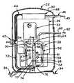
- FIG. 1is a partial sectional view of a compressor illustrating a first embodiment of the present invention
- FIG. 2is a partial sectional view of FIG. 1 taken along line 2 — 2 ;
- FIG. 3is a sectional view of a compressor illustrating a second embodiment of the present invention.
- thermoelectric device (TED) 20is mounted in a hermetic refrigerant compressor 22 to remove heat from suction pressure gas prior to compression thereof.
- a TEDacts as a heat sink or a thermoelectric cooler to remove heat from one surface and transfer it to another surface.
- heatcan be transferred from suction pressure refrigerant in a suction conduit or plenum where high temperatures are undesirable.
- the compressor efficiencymay be improved as heat is removed from the suction pressure gas to be compressed.
- TED 20may be in the form of a thin film such as is described in U.S. Pat. Nos. 6,300,150 and 6,505,468 to Venkatasubramanian, the disclosures of which are hereby expressly incorporated herein by reference.
- the thin film TEDis mounted to the conduit or plenum surface using any suitable method, such as by clamping or adhesion.
- TED 20may operate under the Peltier or Seebeck effect.
- TED 24is electrically powered, absorbing heat energy from one surface and transferring the heat to a second surface as electrical current passes therethrough.
- the TEDis constructed from two dissimilar semiconductors joined to form a closed circuit. According to the Peliter effect, as electrical current flows through the circuit from the first type of semiconductor to the second type of semiconductor, the electrical current creates a temperature gradient across the TED when thermal energy is absorbed at a first, or cold junction of the semiconductors. The heat energy is transported through the semiconductors and is discharged at a second, or hot, junction of the semiconductors.
- TED 24has a cold side in contact with the surface from which heat is being drawn. As the electrical current passes through electrically powered or active TED 24 , heat is drawn from that surface in contact with the TED, cooling the surface. The heat is transferred to a hot side of TED 24 from which it is dissipated using any suitable method, Electrically powered or active TED 24 requires a small amount of electrical current to operate.
- the currentmay be supplied by any suitable method including a battery mounted in the compressor, or the terminal assembly of the compressor as shown. This type of TED may be used in any number of location including being embedded in the cylinder head of a reciprocating piston compressor between a suction and discharge plenum, for example.
- TED 24is in contact with the surface of a wall portion defining the suction plenum and the surface of a wall portion defining the discharge plenum. Heat in the suction plenum wall portion, and thus the suction pressure refrigerant located in the plenum, is transferred to one side of the TED, cooling the wall portion surface and thus the refrigerant. The heat energy is then transferred to the opposite side of TED 24 , the discharge plenum wall portion, and the discharge pressure gas located in the discharge plenum.
- TED 20may operate under the Seebeck effect.
- TED 28( FIG. 3 ) is passive, converting thermal energy conductively received from the surface on which the TED is mounted to electrical energy with the TED acting as a thermoelectric generator or TEG.
- the TEGis constructed similarly to the TED discussed above having two dissimilar semiconductors assembled to form a cold and hot junction. According to the Seebeck effect, electrical current flows continuously in a closed circuit formed from dissimilar metals providing the junctions of the metals are maintained at different temperatures.
- the energy used to drive passive TEG 28is the heat from the mounting surface, or suction conduit, thereby eliminating the need for a supply of electrical current to the TED.
- the conduit surface and thus the refrigerant flowing through the conduitis cooled.
- the electrical energy generated by passive TEG 28 from the captured thermal energyis electrically transferred to resistor 26 .
- Resistor 26is illustrated in FIG. 3 as being mounted to the interior surface of compressor housing 30 .
- the heat drawn from the suction conduit, and thus the refrigerant flowing therethrough, by passive TEG 28is electrically transferred to resistor 26 via wires 32 so that the heat may be dissipated from compressor 22 .
- Resistor 26is mounted to the interior surface of compressor housing 30 by any suitable method including adhesive, clamping, fastening, or the like, which places the resistor in conductive contact with the housing. As air moves around the compressor, the heat in compressor housing 30 is dissipated by natural convection.
- Heat sink or fins 33may be mounted to the outer surface of compressor housing 30 in alignment with resistor 26 to facilitate convective transfer from the housing. Heat in housing 30 is conductively transferred to heat sink 33 and then transferred by convection to the air surrounding compressor 22 .
- TED 20may be adapted for use in any suitable hermetic compressor such as, for example, the compressor described in U.S. patent application Ser. No. 09/994,236 to Tomell et al., published on Jul. 25, 2002, the disclosure of which is hereby expressly incorporated herein by reference.
- TED 20is shown in a specific application being mounted in hermetic compressor 22 (FIGS. 1 and 3 ).
- Compressor 22is illustrated as being supported in a substantially vertical orientation by mounting feet 34 , however, compressor 22 may also be oriented in a substantially horizontal position.
- Compressor 22includes thermally conductive housing 30 in which motor 36 and compression mechanism 38 are mounted. Motor 36 and compression mechanism 38 are operatively coupled by drive shaft 40 (FIG. 3 ).
- Compression mechanism 38may be of any suitable type known in the art including a scroll, reciprocating piston, or rotary type compression mechanism.
- Motor 36includes a stator having stator windings and a rotor. As is typical, electrical current is directed from an external power source (not shown) through terminal assembly 42 mounted in housing 30 . Terminal assembly 42 is electrically connected to the stator windings by wires 44 and when energized, electromagnetically induces rotation of the rotor. Rotation of the rotor drives drive shaft 40 and thus compression mechanism 38 .
- compressor 22 ′is a reciprocating piston compressor. Suction pressure gas is drawn into compressor housing 30 in the direction of arrow 45 , through suction conduit 46 leading into motor end cap 48 . The suction pressure gas enters compressor housing 30 and end cap 48 , flowing over motor 36 , to cool the motor. Heat generated during operation of motor 36 is transferred by convection to the suction pressure gas. The suction pressure gas enters cylinder head 52 of compression mechanism 38 . Cylinder head 52 has suction plenum 50 and discharge plenum 56 defined therein being separated by wall 58 . Cover 51 (FIG. 2 ), which has been removed from FIG.
- the suction pressure gasfirst enters suction plenum 50 formed in cylinder head 52 via suction muffler 53 and suction conduit 54 .
- the suction pressure gasexits plenum 50 through outlet port 55 operable by valve 57 ( FIG. 2 ) to be compressed in compression mechanism 38 to a substantially higher, discharge pressure.
- the discharge pressure gasenters discharge plenum 56 also formed in cylinder head 52 through inlet port 59 operable by valve 61 .
- the discharge pressure gasexits cylinder head 52 via discharge conduit 60 in the direction of arrow 62 and returns to the refrigeration system.
- electrically powered, or active TED 24is embedded in separating wall 58 of cylinder head 52 with TED 24 defining suction plenum wall portion 64 and discharge plenum wall portion 66 .
- Cylinder head 52may be formed by any conventional method including casting, or the like from a material, such as cast iron, able to withstand the pressures created during compressor operation.
- Slot 68is formed in cylinder head 52 to receive TED 24 which may be mounted therein by an interference fit, for example. Thermally conductive adhesives, epoxies, grease, or the like may be used between interfacing surfaces of TED 24 and wall portions 64 and 66 to improve conductivity and/or help secure TED 24 in place.
- TED 24is illustrated as being electrically connected to terminal assembly 42 via wires 70 to receive electrical power from the external power supply which electrically activates both motor 36 and TED 24 .
- TED 24is operated by DC power, therefore, diode or rectifier 72 is located along wires 70 to convert AC power from the external power source to DC power.
- TED 24may be battery operated, eliminating the connection with terminal assembly 42 and rectifier 72 .
- the electrical power required by TED 24is less than that of motor 36 , and therefore a power control device of any suitable type familiar to one of ordinary skill in the art may also be provided between the terminal body and the TED.
- TED 24has cold side 74 in contact with suction plenum wall portion 64 and hot side 76 in contact with discharge plenum wall portion 66 such that heat from suction plenum 50 is transferred to discharge plenum 56 in the direction of arrow 77 .
- the electrical poweractivates TED 24 to absorb heat from the suction pressure refrigerant gas, such as the heat transferred thereto from motor 36 , and conductively transfer the heat through suction plenum wall portion 64 to cold side 74 of TED 24 .
- Operation of TED 24causes the heat to be transferred to hot side 76 of TED 24 as described above and to discharge plenum wall portion 66 by conduction with the temperature of hot side 76 being greater than that of wall portion 66 .
- discharge pressure gasflows through discharge plenum 56 , the heat is transferred by convection to the discharge pressure gas being exhausted from compressor 22 ′.
- compressor 22 ′′may be a scroll or rotary compressor, for example.
- Refrigerant substantially at suction pressureis drawn into compressor housing 30 in the direction of arrow 78 through suction tube 80 mounted in housing 30 by any suitable method including welding, brazing, or the like.
- Suction conduit 81is open to the interior of housing 30 , and draws refrigerant at substantially suction pressure therefrom to convey it to the inlet of compression mechanism 38 .
- Conduit 81may be provided with suction muffler 82 to reduce the amount of noise produced during compressor operation.
- TED 20is illustrated as being mounted on suction muffler 82 , however, the TED may be mounted on suction conduit 81 at any location to remove heat from suction pressure gas entering the compression mechanism.
- the suction pressure gasis compressed in compression mechanism 38 to a substantially higher, discharge pressure which is exhausted from compression mechanism 38 into end 84 of shock tube or discharge conduit 86 .
- a discharge muffler(not shown) may be located along discharge conduit 86 to further reduce undesirable noise produced during compressor operation.
- the opposite end 88 of discharge conduit 86is mounted in compressor housing 30 by welding, brazing, or the like. Compressed refrigerant gas exits end 88 of discharge conduit 86 in the direction of arrow 90 and returns to the refrigeration system.
- TED 20is passive and acts as TEG 28 discussed above.
- Thermal energy from suction conduit muffler 82is conductively transferred to TEG 28 to drive the thermoelectric device and generate electrical energy, rather than being supplied with the electrical connection of the first embodiment between TED 20 and terminal assembly 42 .
- TEG 28converts the thermal energy to electrical energy which is conducted to resistor 26 through wires 32 .
- the heat generated by resistor 26is conducted to the wall of the compressor housing and dissipated from compressor 22 ′′.
- resistor 26is mounted to the interior surface of compressor housing 30 .
- the heat transferred from resistor 26flows into compressor housing 30 by conduction with air surrounding compressor 22 ′′ lifting the heat therefrom by natural convection, thus enhancing heat flow through compressor 22 ′′.
- Finned heat sink 33may be mounted to the outer surface of housing 30 to facilitate the transfer of heat from the housing.
- Compressor 22 described above and illustrated in FIGS. 1 and 3is a low-side compressor.
- a low-side compressoris one in which suction pressure gas surrounds and cools the motor.
- the suction pressure gas in the housingis drawn into the compression mechanism through a suction conduit and/or suction plenum.
- the suction pressure gasis compressed with the discharge pressure gas exiting the compressor through a discharge conduit and/or discharge plenum.
- the TED of the present inventionmay also be adapted for use in a high-side compressor in which the motor is surrounded by substantially by discharge pressure gas.
- suction pressure gasis drawn directly into the compression mechanism through a suction conduit to which the TED may be mounted to remove heat from the suction pressure refrigerant flowing therethrough in the same manner described above.
- TED 20does not have to be mounted only to a suction conduit or between the suction and discharge plenums. TED 20 may be located in a hermetic compressor housing at any location where heat removal is desired.
Landscapes
- Engineering & Computer Science (AREA)
- Mechanical Engineering (AREA)
- General Engineering & Computer Science (AREA)
- Physics & Mathematics (AREA)
- Thermal Sciences (AREA)
- Compressor (AREA)
- Applications Or Details Of Rotary Compressors (AREA)
Abstract
Description
Claims (22)
Priority Applications (2)
| Application Number | Priority Date | Filing Date | Title |
|---|---|---|---|
| US10/457,190US6941761B2 (en) | 2003-06-09 | 2003-06-09 | Thermoelectric heat lifting application |
| CA002466405ACA2466405C (en) | 2003-06-09 | 2004-05-05 | Thermoelectric heat lifting application |
Applications Claiming Priority (1)
| Application Number | Priority Date | Filing Date | Title |
|---|---|---|---|
| US10/457,190US6941761B2 (en) | 2003-06-09 | 2003-06-09 | Thermoelectric heat lifting application |
Publications (2)
| Publication Number | Publication Date |
|---|---|
| US20040244385A1 US20040244385A1 (en) | 2004-12-09 |
| US6941761B2true US6941761B2 (en) | 2005-09-13 |
Family
ID=33490314
Family Applications (1)
| Application Number | Title | Priority Date | Filing Date |
|---|---|---|---|
| US10/457,190Expired - Fee RelatedUS6941761B2 (en) | 2003-06-09 | 2003-06-09 | Thermoelectric heat lifting application |
Country Status (2)
| Country | Link |
|---|---|
| US (1) | US6941761B2 (en) |
| CA (1) | CA2466405C (en) |
Cited By (5)
| Publication number | Priority date | Publication date | Assignee | Title |
|---|---|---|---|---|
| US20040251869A1 (en)* | 2003-05-20 | 2004-12-16 | Pierre Vadstrup | Electric motor |
| US7278269B2 (en) | 2005-11-09 | 2007-10-09 | Emerson Climate Technologies, Inc. | Refrigeration system including thermoelectric module |
| US7296416B2 (en)* | 2005-11-09 | 2007-11-20 | Emerson Climate Technologies, Inc. | Vapor compression circuit and method including a thermoelectric device |
| US20070283702A1 (en)* | 2005-05-06 | 2007-12-13 | Strnad Richard J | Dual heat to cooling converter |
| US20080229759A1 (en)* | 2007-03-21 | 2008-09-25 | Chien Ouyang | Method and apparatus for cooling integrated circuit chips using recycled power |
Families Citing this family (6)
| Publication number | Priority date | Publication date | Assignee | Title |
|---|---|---|---|---|
| US7610993B2 (en)* | 2005-08-26 | 2009-11-03 | John Timothy Sullivan | Flow-through mufflers with optional thermo-electric, sound cancellation, and tuning capabilities |
| ES2328766B1 (en)* | 2006-12-27 | 2010-09-06 | Pablo Flores Peña | DEVICE COOLING A FLUID CURRENT OBTAINING ALSO ELECTRICAL ENERGY. |
| CN101784846A (en)* | 2007-08-14 | 2010-07-21 | 开利公司 | thermoelectric cooler for compressor motor |
| US20120204577A1 (en)* | 2011-02-16 | 2012-08-16 | Ludwig Lester F | Flexible modular hierarchical adaptively controlled electronic-system cooling and energy harvesting for IC chip packaging, printed circuit boards, subsystems, cages, racks, IT rooms, and data centers using quantum and classical thermoelectric materials |
| US10208978B2 (en)* | 2012-11-08 | 2019-02-19 | Lennox Industries Inc. | System for generating electrical energy from waste energy |
| CN103994075A (en)* | 2014-05-20 | 2014-08-20 | 广东美芝精密制造有限公司 | Compressor |
Citations (33)
| Publication number | Priority date | Publication date | Assignee | Title |
|---|---|---|---|---|
| US3212274A (en) | 1964-07-28 | 1965-10-19 | Eidus William | Thermoelectric condenser |
| US3817043A (en) | 1972-12-07 | 1974-06-18 | Petronilo C Constantino & Ass | Automobile air conditioning system employing thermoelectric devices |
| US4493939A (en) | 1983-10-31 | 1985-01-15 | Varo, Inc. | Method and apparatus for fabricating a thermoelectric array |
| US4576009A (en)* | 1984-01-31 | 1986-03-18 | Mitsubishi Denki Kabushiki Kaisha | Heat transmission device |
| US5006505A (en) | 1988-08-08 | 1991-04-09 | Hughes Aircraft Company | Peltier cooling stage utilizing a superconductor-semiconductor junction |
| US5180293A (en) | 1992-03-20 | 1993-01-19 | Hewlett-Packard Company | Thermoelectrically cooled pumping system |
| US5361587A (en) | 1993-05-25 | 1994-11-08 | Paul Georgeades | Vapor-compression-cycle refrigeration system having a thermoelectric condenser |
| US5402644A (en) | 1994-03-16 | 1995-04-04 | O.R. Solutions, Inc. | Method for maintaining sterile slush |
| US5411599A (en) | 1993-09-20 | 1995-05-02 | The United States Of America As Represented The Secretary Of The Army | Thermoelectric device utilizing nanoporous material |
| US5436467A (en) | 1994-01-24 | 1995-07-25 | Elsner; Norbert B. | Superlattice quantum well thermoelectric material |
| US5782106A (en) | 1995-12-29 | 1998-07-21 | Lg Electronics Inc. | refrigerator having warmer compartment |
| US5890371A (en) | 1996-07-12 | 1999-04-06 | Thermotek, Inc. | Hybrid air conditioning system and a method therefor |
| US5900071A (en) | 1993-01-12 | 1999-05-04 | Massachusetts Institute Of Technology | Superlattice structures particularly suitable for use as thermoelectric materials |
| US5952728A (en) | 1995-11-13 | 1999-09-14 | Ngk Insulators, Ltd. | Thermoelectric conversion module having channels filled with semiconducting material and insulating fillers |
| US6003319A (en) | 1995-10-17 | 1999-12-21 | Marlow Industries, Inc. | Thermoelectric refrigerator with evaporating/condensing heat exchanger |
| US6058711A (en) | 1996-08-12 | 2000-05-09 | Centre National D'etudes Spatiales | Capillary evaporator for diphasic loop of energy transfer between a hot source and a cold source |
| US6060656A (en) | 1997-03-17 | 2000-05-09 | Regents Of The University Of California | Si/SiGe superlattice structures for use in thermoelectric devices |
| US6107645A (en) | 1997-10-31 | 2000-08-22 | Fujitsu Limited | Thermoelectric system using semiconductor |
| US6148635A (en) | 1998-10-19 | 2000-11-21 | The Board Of Trustees Of The University Of Illinois | Active compressor vapor compression cycle integrated heat transfer device |
| US6158225A (en) | 1997-12-10 | 2000-12-12 | Seiko Seiki Kabushiki Kaisha | Automotive air-conditioning apparatus |
| US6213198B1 (en) | 1995-12-13 | 2001-04-10 | Denso Corporation | Air conditioning apparatus for vehicle with thermoelectric dehumidifier in a double layer system |
| US6293107B1 (en) | 1996-11-08 | 2001-09-25 | Matsushita Refrigeration Company | Thermoelectric cooling system |
| US6298669B1 (en)* | 1999-11-02 | 2001-10-09 | Smc Corporation | Pipe cooler and small-sized temperature controlling apparatus using the same |
| US6300150B1 (en) | 1997-03-31 | 2001-10-09 | Research Triangle Institute | Thin-film thermoelectric device and fabrication method of same |
| US6338251B1 (en) | 1999-07-22 | 2002-01-15 | International Business Machines Corporation | Mixed thermoelectric cooling apparatus and method |
| US6345506B1 (en) | 1999-03-18 | 2002-02-12 | Cse Inc. | Apparatus for controlling temperature of fluid by use of thermoelectric device |
| US6351950B1 (en) | 1997-09-05 | 2002-03-05 | Fisher & Paykel Limited | Refrigeration system with variable sub-cooling |
| US6385976B1 (en) | 2000-09-08 | 2002-05-14 | Ferrotec (Usa) Corporation | Thermoelectric module with integrated heat exchanger and method of use |
| US20020073716A1 (en) | 2000-12-19 | 2002-06-20 | William Melaragni | Thermoelectric cooler temperature control |
| US6410971B1 (en) | 2001-07-12 | 2002-06-25 | Ferrotec (Usa) Corporation | Thermoelectric module with thin film substrates |
| US6418729B1 (en) | 1998-05-14 | 2002-07-16 | Consejo Superior De Investigaciones Cientificas | Domestic refrigerator with peltier effect, heat accumulators and evaporative thermosyphons |
| US20020098093A1 (en) | 2000-12-01 | 2002-07-25 | Tomell Phillip A. | Reciprocating piston compressor having improved noise attenuation |
| US6505468B2 (en) | 2000-03-21 | 2003-01-14 | Research Triangle Institute | Cascade cryogenic thermoelectric cooler for cryogenic and room temperature applications |
Family Cites Families (3)
| Publication number | Priority date | Publication date | Assignee | Title |
|---|---|---|---|---|
| US73718A (en)* | 1868-01-28 | Improvement in stove-pipe coupling | ||
| US98093A (en)* | 1869-12-21 | Thomas newell | ||
| CA2225159C (en)* | 1996-12-19 | 2006-10-17 | Showa Pole Co., Ltd. | Pole having solar cells |
- 2003
- 2003-06-09USUS10/457,190patent/US6941761B2/ennot_activeExpired - Fee Related
- 2004
- 2004-05-05CACA002466405Apatent/CA2466405C/ennot_activeExpired - Fee Related
Patent Citations (35)
| Publication number | Priority date | Publication date | Assignee | Title |
|---|---|---|---|---|
| US3212274A (en) | 1964-07-28 | 1965-10-19 | Eidus William | Thermoelectric condenser |
| US3817043A (en) | 1972-12-07 | 1974-06-18 | Petronilo C Constantino & Ass | Automobile air conditioning system employing thermoelectric devices |
| US4493939A (en) | 1983-10-31 | 1985-01-15 | Varo, Inc. | Method and apparatus for fabricating a thermoelectric array |
| US4576009A (en)* | 1984-01-31 | 1986-03-18 | Mitsubishi Denki Kabushiki Kaisha | Heat transmission device |
| US5006505A (en) | 1988-08-08 | 1991-04-09 | Hughes Aircraft Company | Peltier cooling stage utilizing a superconductor-semiconductor junction |
| US5180293A (en) | 1992-03-20 | 1993-01-19 | Hewlett-Packard Company | Thermoelectrically cooled pumping system |
| US5900071A (en) | 1993-01-12 | 1999-05-04 | Massachusetts Institute Of Technology | Superlattice structures particularly suitable for use as thermoelectric materials |
| US5361587A (en) | 1993-05-25 | 1994-11-08 | Paul Georgeades | Vapor-compression-cycle refrigeration system having a thermoelectric condenser |
| US5411599A (en) | 1993-09-20 | 1995-05-02 | The United States Of America As Represented The Secretary Of The Army | Thermoelectric device utilizing nanoporous material |
| US5436467A (en) | 1994-01-24 | 1995-07-25 | Elsner; Norbert B. | Superlattice quantum well thermoelectric material |
| US5551240A (en) | 1994-03-16 | 1996-09-03 | O. R. Solutions, Inc. | Method and apparatus for maintaining temperature control of sterile fluid |
| US5402644A (en) | 1994-03-16 | 1995-04-04 | O.R. Solutions, Inc. | Method for maintaining sterile slush |
| US6003319A (en) | 1995-10-17 | 1999-12-21 | Marlow Industries, Inc. | Thermoelectric refrigerator with evaporating/condensing heat exchanger |
| US5952728A (en) | 1995-11-13 | 1999-09-14 | Ngk Insulators, Ltd. | Thermoelectric conversion module having channels filled with semiconducting material and insulating fillers |
| US6213198B1 (en) | 1995-12-13 | 2001-04-10 | Denso Corporation | Air conditioning apparatus for vehicle with thermoelectric dehumidifier in a double layer system |
| US5782106A (en) | 1995-12-29 | 1998-07-21 | Lg Electronics Inc. | refrigerator having warmer compartment |
| US6058712A (en) | 1996-07-12 | 2000-05-09 | Thermotek, Inc. | Hybrid air conditioning system and a method therefor |
| US5890371A (en) | 1996-07-12 | 1999-04-06 | Thermotek, Inc. | Hybrid air conditioning system and a method therefor |
| US6058711A (en) | 1996-08-12 | 2000-05-09 | Centre National D'etudes Spatiales | Capillary evaporator for diphasic loop of energy transfer between a hot source and a cold source |
| US6293107B1 (en) | 1996-11-08 | 2001-09-25 | Matsushita Refrigeration Company | Thermoelectric cooling system |
| US6060656A (en) | 1997-03-17 | 2000-05-09 | Regents Of The University Of California | Si/SiGe superlattice structures for use in thermoelectric devices |
| US6300150B1 (en) | 1997-03-31 | 2001-10-09 | Research Triangle Institute | Thin-film thermoelectric device and fabrication method of same |
| US6351950B1 (en) | 1997-09-05 | 2002-03-05 | Fisher & Paykel Limited | Refrigeration system with variable sub-cooling |
| US6107645A (en) | 1997-10-31 | 2000-08-22 | Fujitsu Limited | Thermoelectric system using semiconductor |
| US6158225A (en) | 1997-12-10 | 2000-12-12 | Seiko Seiki Kabushiki Kaisha | Automotive air-conditioning apparatus |
| US6418729B1 (en) | 1998-05-14 | 2002-07-16 | Consejo Superior De Investigaciones Cientificas | Domestic refrigerator with peltier effect, heat accumulators and evaporative thermosyphons |
| US6148635A (en) | 1998-10-19 | 2000-11-21 | The Board Of Trustees Of The University Of Illinois | Active compressor vapor compression cycle integrated heat transfer device |
| US6345506B1 (en) | 1999-03-18 | 2002-02-12 | Cse Inc. | Apparatus for controlling temperature of fluid by use of thermoelectric device |
| US6338251B1 (en) | 1999-07-22 | 2002-01-15 | International Business Machines Corporation | Mixed thermoelectric cooling apparatus and method |
| US6298669B1 (en)* | 1999-11-02 | 2001-10-09 | Smc Corporation | Pipe cooler and small-sized temperature controlling apparatus using the same |
| US6505468B2 (en) | 2000-03-21 | 2003-01-14 | Research Triangle Institute | Cascade cryogenic thermoelectric cooler for cryogenic and room temperature applications |
| US6385976B1 (en) | 2000-09-08 | 2002-05-14 | Ferrotec (Usa) Corporation | Thermoelectric module with integrated heat exchanger and method of use |
| US20020098093A1 (en) | 2000-12-01 | 2002-07-25 | Tomell Phillip A. | Reciprocating piston compressor having improved noise attenuation |
| US20020073716A1 (en) | 2000-12-19 | 2002-06-20 | William Melaragni | Thermoelectric cooler temperature control |
| US6410971B1 (en) | 2001-07-12 | 2002-06-25 | Ferrotec (Usa) Corporation | Thermoelectric module with thin film substrates |
Non-Patent Citations (8)
| Title |
|---|
| Introduction to Thermoelectric Coding, Ferrotec America Corporation, 1998. |
| Loh, et al., Investigation into the use of Thermoelectric Devices as Heat Source for Heat Sink Characterization, unknown date. |
| Mahan, G.D., Sofo, J.O. & Bartkowiak, M., Multilayer Thermionic Refrigerator and Generator, J. Appl. Phys. vol. 83, No. 9, 4683, 1998. |
| Mahan, G.D., Thermionic Refrigeration, J. Appl. Phys. 76(7), 4362, 1994. |
| Peltier Device Information Directory, Steve J. Noll, 1999-2002. |
| Thermoelectric Powered Wristwatch, Zt-Spam, 3 pages, 1998-1999. |
| Vining, C.B. & Mahan, G.D., The B factor in multilayer thermionic refrigeration. Journal of Applied Physics, vol. 86, No. 12, 6852-6853, 1999. |
| Vining, C.B., Semiconductors are cool, Nature 413, 577-578, Oct. 11, 2001. |
Cited By (10)
| Publication number | Priority date | Publication date | Assignee | Title |
|---|---|---|---|---|
| US20040251869A1 (en)* | 2003-05-20 | 2004-12-16 | Pierre Vadstrup | Electric motor |
| US7317296B2 (en)* | 2003-05-20 | 2008-01-08 | Grundfos A/S | Electric motor |
| US20070283702A1 (en)* | 2005-05-06 | 2007-12-13 | Strnad Richard J | Dual heat to cooling converter |
| US7278269B2 (en) | 2005-11-09 | 2007-10-09 | Emerson Climate Technologies, Inc. | Refrigeration system including thermoelectric module |
| US7284379B2 (en) | 2005-11-09 | 2007-10-23 | Emerson Climate Technologies, Inc. | Refrigeration system including thermoelectric module |
| US7296416B2 (en)* | 2005-11-09 | 2007-11-20 | Emerson Climate Technologies, Inc. | Vapor compression circuit and method including a thermoelectric device |
| US7310953B2 (en) | 2005-11-09 | 2007-12-25 | Emerson Climate Technologies, Inc. | Refrigeration system including thermoelectric module |
| US7752852B2 (en)* | 2005-11-09 | 2010-07-13 | Emerson Climate Technologies, Inc. | Vapor compression circuit and method including a thermoelectric device |
| US8307663B2 (en) | 2005-11-09 | 2012-11-13 | Emerson Climate Technologies, Inc. | Vapor compression circuit and method including a thermoelectric device |
| US20080229759A1 (en)* | 2007-03-21 | 2008-09-25 | Chien Ouyang | Method and apparatus for cooling integrated circuit chips using recycled power |
Also Published As
| Publication number | Publication date |
|---|---|
| CA2466405C (en) | 2007-03-27 |
| CA2466405A1 (en) | 2004-12-09 |
| US20040244385A1 (en) | 2004-12-09 |
Similar Documents
| Publication | Publication Date | Title |
|---|---|---|
| US6941761B2 (en) | Thermoelectric heat lifting application | |
| US20100146990A1 (en) | Thermoelectric cooler for compressor motor | |
| JP2001349651A (en) | Withdrawing liquid cooling device using phase change coolant | |
| US20070163274A1 (en) | Method & arrangement for cooling a substrate, particularly a semiconductor | |
| JP2009150237A (en) | Motor-driven compressor | |
| JPH062678A (en) | Closed type rotary compressor | |
| US8011900B2 (en) | Hermetic compressor with a heat dissipation system | |
| US20100101242A1 (en) | System and method for cooling air conditioning system electronics | |
| US7140197B2 (en) | Means and apparatus for microrefrigeration | |
| JP4300637B2 (en) | Heating / cooling device | |
| JP2953367B2 (en) | LSI cooling system | |
| GB2503516A (en) | A refrigeration compressor for a vehicles HVAC device with a water cooling jacket connected to the vehicles engine coolant circuit. | |
| US12052849B2 (en) | Heat engine | |
| JP3240816B2 (en) | Electronic cooling unit | |
| JPS6245099Y2 (en) | ||
| KR19990053414A (en) | Compressor chiller of refrigerator | |
| KR100339602B1 (en) | Cooling apparatus for pulstube cryogenic refrigerator | |
| KR19980025980A (en) | Compressor Chiller using Heat Pipe | |
| CN106286307A (en) | High back pressure compressors, air conditioning systems and refrigeration equipment | |
| KR19990035496A (en) | Chiller of refrigerator | |
| JPS58140496A (en) | Rotary compressor cooling system | |
| KR20000013435U (en) | Discharge Muffler Integrated Valve Assembly Structure of Hermetic Compressor | |
| JPS597038B2 (en) | Cooling structure of rotary compressor | |
| JP2008157170A (en) | Electric compressor | |
| KR20020067294A (en) | Radiating apparatus for cryocooler |
Legal Events
| Date | Code | Title | Description |
|---|---|---|---|
| AS | Assignment | Owner name:TECUMSEH PRODUCTS COMPANY, MICHIGAN Free format text:ASSIGNMENT OF ASSIGNORS INTEREST;ASSIGNORS:GATECLIFF, GEORGE W.;HORTON, WILLIAM T.;REEL/FRAME:014504/0659 Effective date:20030908 | |
| AS | Assignment | Owner name:JPMORGAN CHASE BANK, N.A.,MICHIGAN Free format text:SECURITY AGREEMENT;ASSIGNOR:TECUMSEH PRODUCTS COMPANY;REEL/FRAME:016641/0380 Effective date:20050930 Owner name:JPMORGAN CHASE BANK, N.A., MICHIGAN Free format text:SECURITY AGREEMENT;ASSIGNOR:TECUMSEH PRODUCTS COMPANY;REEL/FRAME:016641/0380 Effective date:20050930 | |
| AS | Assignment | Owner name:CITICORP USA, INC.,NEW YORK Free format text:SECURITY INTEREST;ASSIGNORS:TECUMSEH PRODUCTS COMPANY;CONVERGENT TECHNOLOGIES INTERNATIONAL, INC.;TECUMSEH TRADING COMPANY;AND OTHERS;REEL/FRAME:017606/0644 Effective date:20060206 Owner name:CITICORP USA, INC., NEW YORK Free format text:SECURITY INTEREST;ASSIGNORS:TECUMSEH PRODUCTS COMPANY;CONVERGENT TECHNOLOGIES INTERNATIONAL, INC.;TECUMSEH TRADING COMPANY;AND OTHERS;REEL/FRAME:017606/0644 Effective date:20060206 | |
| AS | Assignment | Owner name:JPMORGAN CHASE BANK, N.A., NEW YORK Free format text:SECURITY AGREEMENT;ASSIGNORS:TECUMSEH PRODUCTS COMPANY;TECUMSEH COMPRESSOR COMPANY;VON WEISE USA, INC.;AND OTHERS;REEL/FRAME:020995/0940 Effective date:20080320 Owner name:JPMORGAN CHASE BANK, N.A.,NEW YORK Free format text:SECURITY AGREEMENT;ASSIGNORS:TECUMSEH PRODUCTS COMPANY;TECUMSEH COMPRESSOR COMPANY;VON WEISE USA, INC.;AND OTHERS;REEL/FRAME:020995/0940 Effective date:20080320 | |
| REMI | Maintenance fee reminder mailed | ||
| LAPS | Lapse for failure to pay maintenance fees | ||
| STCH | Information on status: patent discontinuation | Free format text:PATENT EXPIRED DUE TO NONPAYMENT OF MAINTENANCE FEES UNDER 37 CFR 1.362 | |
| FP | Lapsed due to failure to pay maintenance fee | Effective date:20090913 |