US6941482B2 - Systems and methods for synchronizing time stamps - Google Patents
Systems and methods for synchronizing time stampsDownload PDFInfo
- Publication number
- US6941482B2 US6941482B2US10/238,358US23835802AUS6941482B2US 6941482 B2US6941482 B2US 6941482B2US 23835802 AUS23835802 AUS 23835802AUS 6941482 B2US6941482 B2US 6941482B2
- Authority
- US
- United States
- Prior art keywords
- signal
- box
- ports
- domain
- time stamp
- Prior art date
- Legal status (The legal status is an assumption and is not a legal conclusion. Google has not performed a legal analysis and makes no representation as to the accuracy of the status listed.)
- Expired - Lifetime, expires
Links
Images


Classifications
- G—PHYSICS
- G06—COMPUTING OR CALCULATING; COUNTING
- G06F—ELECTRIC DIGITAL DATA PROCESSING
- G06F1/00—Details not covered by groups G06F3/00 - G06F13/00 and G06F21/00
- G06F1/04—Generating or distributing clock signals or signals derived directly therefrom
- G06F1/14—Time supervision arrangements, e.g. real time clock
Definitions
- the present inventionrelates to synchronizing time stamp counters of ports within a domain and to synchronizing start, stop and trigger signals to ports in the domain. More particularly, the present invention relates to systems and methods for synchronizing the time stamp counters of ports in a domain across different boxes and across different technologies or protocols.
- Computer networksare ubiquitous today. Almost every home and business is connected to the Internet and many have their own internal networks. Not surprisingly, those internal networks are also connected with other computer networks.
- One of the primary advantages of computer networksis the ability to send data from one computer to another.
- the task of routing data from one computer to another computeris not always a simple task.
- the datais routed from one computer or network to another computer or network using routers, switching networks, or other types of gateways. These gateways or switching networks often provide physical connections or ports to various networks.
- the portsare often provided, for example, on a card that is often contained in a chassis with a common backplane or bus.
- the chassisis often mounted to a rack.
- the chassisis modular thereby allowing multiple chassis to be mounted to the rack.
- Each chassissupports a particular number of blades and each blade supports a particular number of ports.
- the number of blades supported by a particular box and the number of ports supported by a particular blade and the distance from one chassis to anotheris hardware dependent, but the present invention is not limited by hardware constraints.
- each portmay be driven by a different clock, frequency or other control signal.
- each portis typically associated with a time stamp counter that can produce time stamp values. Time stamp values are often used to analyze the data that was present on the ports when a particular event or condition is detected.
- the primary problemis synchronizing the time stamp counters such that the time stamp values associated with various ports can be used to identify the data that was present on the ports at a given time or during a certain time interval and be used to measure the latency from one port to another and be used to control the domain of ports simultaneously creating one large virtual port with a common time stamp counter.
- This large virtual port that includes the physical ports in a user defined domaincan be used to simultaneously monitor data and troubleshoot many interconnection issues between disparate devices (routers, switches, host computers, adapter cards, etc.) in a network that may be of different protocols (Fibre Channel, Ethernet, etc.) and may not be geographically co-located.
- the present inventionis directed to synchronizing ports that are in a domain and more particularly to synchronizing ports in a domain that is spread across different blades, chassis, backplanes, boxes, and/or protocols.
- the present inventionis also directed to starting, stopping and triggering the ports at substantially the same time within a particular domain.
- the time stamp counter for that portbegins counting.
- the time stamp counter of that portstops counting.
- data at the portis captured and stored.
- the present inventionenables a user to associate ports into one or more domains and enables the ports that belong to a particular domain to be monitored, started, stopped, and/or triggered.
- the ports in a particular domainare of different technologies or protocols that have inherently different characteristics. Some of the ports, for example, may be Ethernet ports while other ports on a different box or on the same box are fibre channel ports.
- Synchronizing the time stamp counters of the ports within a domain across different boxesbegins by identifying a master box.
- the other boxes that have ports within the domainare slave boxes to the master box.
- the master and slave boxesare typically connected in a cascade fashion.
- the clock signals of the slave boxesare tri-stated or disabled such the clock signal generated by the master box is used to drive the time stamp counters of the ports in the master box and in the slave boxes.
- the boxesare connected such that control signals including the clock signal can be distributed from the master box to a slave box. Because the boxes are cascaded, the slave box connected with the master box distributes the appropriate signals to the subsequent slave box. Each slave box thus distributes the appropriate signals to the next slave box in the chain.
- the clock signal from the master boxis multiplied and the multiplied clock signal is used to drive the time stamp counters of the ports on the respective boxes.
- the clock signal generated by the master box or received by a slave boxis adjusted to account for delay that may have been introduced into the clock signal as it is distributed from one box to the next box. For example, the clock signal generated by the master box is set back by a determined amount before it is distributed to the slave box.
- the clock signal at the slave box and at the master boxis synchronized. Because the clock signal from the master box is driving the clock multiplier, the time stamp counters that are subsequently driven by the clock multiplier are substantially synchronized.
- the other control signals used to start, stop and trigger the ports of a particular domainare delivered to each box in a similar manner to ensure that the ports are started, stopped, and/or triggered at substantially the same time.
- a port in a domaintriggers or detects a predetermined condition or event
- the portWhen a port in a domain triggers or detects a predetermined condition or event, the port generates a trigger out signal that is provided to the master box through the control signals.
- the master boxthen asserts the run/stop/trigger signal, which causes the remaining ports in the domain to stop at substantially the same time and perform post trigger events. In this manner, the ports within a domain are synchronized even when the ports are in different locations, technologies and/or protocols.
- FIG. 1illustrates an exemplary box that includes one or more blades that each support one or more ports;
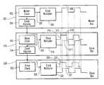
- FIG. 2is a block diagram that illustrates a master box that is cascaded with one or more slave boxes and illustrates the control signals that are distributed from box to box;
- FIG. 3illustrates how the clock signal and the other control signals are adjusted before being distributed to the next box
- FIG. 4illustrates how the ports in a domain are started, stopped, and triggered in a substantially synchronous manner.
- a certain networkrequires the connection of an Ethernet port on one box with a Fibre Channel port on another box.
- a trigger eventis detected that causes the Ethernet port and the Fibre Channel port to start collecting data when the event occurs.
- a useris often interested, for example, in determining the time delay of the data or the amount of time the data takes to travel one-way between the ports, or the time the data takes to travel one-way through a separate network device under test between the ports, or the time the data takes to travel one-way through the network (multiple devices) between the two ports.
- the time stamp counters of the Ethernet port and of the Fibre Channel portare not correlated, it is difficult to ascertain the time delay that occurs between ports in a domain. For the same reasons, it is difficult to correlate the data captured at the Ethernet port with the data captured by the Fibre Channel port. Thus, the data passing through the Fibre Channel port cannot be easily identified as the same data that is passing through the Ethernet port when the Ethernet port triggers.
- the present inventionextends to both methods and systems for synchronizing the time stamp counters on ports within a domain even when the ports support different technologies and/or protocols or are in distinct boxes, or in boxes that are in different locations.
- the present inventionalso extends to systems and methods for starting, stopping and triggering ports that are grouped together within a single domain.
- the present inventionis often tied to a particular hardware implementation. Any particular hardware configuration discussed herein is solely for illustrative purposes and the present invention is not limited to any specific hardware configuration.
- the embodiments of the present inventionmay comprise a special purpose or general-purpose computer including various computer hardware, as discussed in greater detail below.
- each boxsupports up to four blades and each blade can support up to eight ports.
- this configurationcan support eight port domains.
- a domainrefers to a group of ports that are bundled or connected together. Any port in any box can be in any one of the domains. Because the boxes or blades are not necessarily of the same technology, it is possible to have different types of ports within a single domain.
- Each portis associated with a time stamp counter that generates time stamp values. Data passing through the ports is often stamped with the time stamp value obtained from the time stamp counters.
- One advantage of synchronizing the time stamp counters of ports in a domainis that troubleshooting is simplified because of the synchronized time reference that exists between the ports in the domain. Note that if each port in the domain relies solely on the clock of each box, as previously stated, it is difficult to determine when a particular port triggers from the perspective of another port because the time stamp counters of the ports are not related or synchronized.
- FIG. 1is a block diagram that illustrates an exemplary box 100 .
- the box 100includes four blades illustrated as blades 110 , 120 , 130 , and 140 . Each blade supports a plurality of ports (eight in this example).
- the blade 110for example, includes or supports the ports 111 , 112 , 113 , 114 , 115 , 116 , 117 , and 118 .
- the other blades 120 , 130 , and 140 of the box 100similarly include or support a number of ports.
- the box 100includes an oscillator or clock 102 that operates at a certain frequency. Because the ports can often support a high data rate, the clock signal of the clock 102 is multiplied by the clock multiplier 106 and the resulting clock signal of the clock multiplier is used to drive the time stamp counters of each port of each blade. Each time stamp counter of each port is thus driven by the multiplied clock signal generated by the clock multiplier 106 . As described below in more detail, whether a particular time stamp counter is incrementing with the multiplied clock signal depends on the state of the particular port or on the status of another control signal.
- the box 100also includes a field programmable gate array (FPGA) 104 or other similar module.
- the FPGA 104can be used, for example, to direct various signals to various ports.
- the FPGA 104is used to program each port to a particular domain and to set the correct bits from the control signals to the appropriate port.
- the FPGA 104can be programmed via another port from a processor, for example.
- the FPGA 104also performs comparisons that are used to set bits on the port as will be described in more detail below.
- Each portis connected with control signals.
- control signalsinclude, but are not limited to, a time stamp clock from the clock multiplier 106 , a run/stop/trigger (RST) signal, a trigger out (TO) signal, and a state reset (SR) signal.
- the time stamp clockis driven through each blade to each port and drives a time stamp counter for each port.
- the present inventionenables the time stamp clock to be synchronized for all blades and all boxes as will be described.
- RST signalfor each port.
- the RST signalis initially low.
- the time stamp counterbegins and the port is enabled to receive, monitor and/or transmit.
- the portwill trigger and perform any post trigger actions that are required, such as filling a buffer with data.
- TO signalfor each port.
- Each portcan generate a TO signal, which indicates that a trigger event or condition has occurred.
- the TO signal of a portis low when the RST signal for that port goes high.
- Each portalso has a SR signal that causes the port to reset back to an initial or beginning state.
- FIG. 1further illustrates these control signals 150 in more detail.
- the control signals 150include, but are not limited to, a clock out 152 , a clock-in signal 154 , a RST signal 156 , a TO signal 158 , and a SR signal 160 .
- FIG. 1further illustrates that the control signals 150 , in addition as being specific to particular ports as described above, can also be distributed between boxes.
- the clock out 152is typically generated by a master box and is sent to one or more slave boxes (as shown in FIG. 2 ).
- the clock out signal 152is used to synchronize the time stamp counters of the ports in a particular domain.
- the clock signal 154may refer to the clock signal that is received from a previous master or slave box (also shown in FIG. 2 ).
- the RST signal 156is a signal that is used to start/stop/trigger the time stamp counters of ports within a domain of ports.
- the TO signal 158is generated by a port that experiences a trigger event. After a trigger event occurs and the master box receives the TO signal 158 , the RST 156 is used to stop other time stamp counters of ports in the domain where the TO signal 158 initiated.
- the RST signal 156is implemented as two separate control signals. There is a run/stop signal and a trigger signal. These signals have the functions described herein but are implemented as separate signals.
- the time stamp counterswill begin counting when the run/stop signal goes high (or low) and the time stamp counters will stop counting when the run/stop signal goes low (or high).
- the trigger signalwill cause the port to trigger and perform trigger event functions when the trigger signal is asserted.
- FIG. 2is a block diagram that illustrates a series of boxes that are connected by cables.
- the cablesconnect to each box using RJ45 connectors.
- the cablescarry the control signals from one box to the next.
- FIG. 2illustrates boxes that are cascaded together, but the present invention is not limited to a cascaded configuration.
- the box 200is connected with the box 210 by the cable 250 and the box 210 is connected to the box 220 by the cable 252 .
- the boxes 200 , 210 and 220are not required to share a common bus or be co-located, and each box is typically capable of generating an independent clock signal.
- the clock signal of a slave boxis typically disabled or tri-stated such that the clock signal generated and distributed from the master box may be used.
- the clock of box 210 and box 220are not shown to illustrate that the clock 204 of the master box 200 is being used for the time stamp counters of ports within the domain.
- FIG. 2also introduces a domain of ports.
- a domainincludes one or more ports that may be selected from different blades and/or boxes.
- the domain illustrated in FIG. 2includes the port 202 from a blade 201 of the box 200 , a port 212 from a blade 211 of the box 210 , a port 222 from the blade 221 of the box 220 , and a port 224 from a blade 223 of the box 220 .
- the domain illustrated by FIG. 2thus shares ports that are located on different blades of different boxes. Because the boxes do not share a common bus and because a domain can include ports from different boxes, the domain may include ports that use different technologies/protocols.
- the master box 200includes a clock 204 that is distributed to and used by the slave boxes (slave box 210 and slave box 220 ) that have ports included in a particular domain.
- the clock signal from the clock 204 of the master box 200is delivered to the slave box 210 through the control signals 250 .
- the slave box 210delivers the clock signal to the slave box 220 through the control signals 252 .
- the clock multiplier 216 of the slave box 210multiplies the clock signal from the master box 200 and it is the multiplied clock signal (also referred to herein as the time stamp clock) that drives the time stamp counters of the ports on the slave box 210 .
- a clock multiplier at the master box 200is used to drive the time stamp counters of the ports on the master box.
- the clock signal delivered to the box 220is multiplied by the clock multiplier 228 and the multiplied clock signal from the clock multiplier drives the time stamp counters of the slave box 220 . For example, if the clock signal from the clock 204 operates at 25 MHz and the clock multipliers multiply the clock signal by a factor of four, the time stamp counters are driven by a clock signal operating at 100 MHz.
- the clock signalis delivered from the master box 200 to the slave box 210 and from the slave box 210 to the next slave box 220 , it is possible that a delay will be introduced in the clock signal.
- the length of the cable connecting two boxescan introduce a clock delay
- the receivercan introduce a delay
- the line driverscan introduce a delay. If, for example, eight boxes are cascaded together, the time stamps on the last box may be different from the time stamps of the master box.
- FIG. 3illustrates an example of how this delay can be reduced or eliminated.
- the master box 300has a master clock 302 that generates a clock signal 305 .
- the clock signal 305drives the FPGA of the master box, the clock multiplier 306 , and the clock adjuster 304 .
- the clock signal 305is multiplied by the clock multiplier 306 to generate a time stamp clock signal 308 that drives the time stamp counters for all ports on the master box 300 .
- the master box 300includes a clock adjuster 304 that adjusts the clock signal in order to account for this delay. In other words, the rising edge of the output of the clock adjuster 304 precedes the input by the expected delay (on the order of 8 nanoseconds in one example).
- the slave box 310receives a clock signal from the clock adjuster 304 .
- the clock signal 315 generated at the slave box 310is actually the clock signal received from the clock adjuster 304 of the master box 300 .
- the clock signal 315is multiplied by the clock multiplier 316 and distributed to the time stamp counters of the ports of the slave box 310 .
- the clock signal 318represents the clock signal distributed to the time stamp counters of the slave box 310 in the absence of the clock adjuster 304 .
- the clock signal 318thus illustrates that there is a delay 317 between the clock signal of the slave box 310 and the clock signal 308 of the master box 300 .
- the clock signal 311illustrates the clock signal that is actually generated by the slave box 310 .
- the clock signal 311is in sync with the clock signal 308 because of the adjustment made by the clock adjuster 304 .
- FIG. 3illustrates that the time delay 327 of the clock signal 329 that would accumulate in the domain if the clock signal 329 was not adjusted.
- the slave box 310also includes a clock adjuster 314 such that this delay is reduced or eliminated.
- the clock signal 321 , 311 , and 308are synchronized in this manner.
- the slave clocks 312 and 322are effectively disabled or tri-stated and the time stamp counters are all driven from the master clock 302 .
- the clock multipliers 306 , 316 , and 326are also driven by the master clock 302 , the time stamp counters are all substantially synchronized.
- the delay introduced into the master clock signal by the clock adjustersis not equal to the actual delay.
- the time stamp counters of the ports in a domainare within useful bounds of precision even if not perfectly synchronized. In other words, the time stamp counters are sufficiently synchronized such that the time stamp values obtained from the time stamp counters provide useful information that may relate to receiving, monitoring, and/or transmitting data.
- FIG. 4illustrates an example of how the RST signal functions in a domain.
- This exampledescribes a serial protocol, but the present invention can be implemented using other signal protocols.
- the RST signal that originates on a master boxis delivered to each port in a particular domain 418 .
- the serial protocol used for the RST signalcan also be implemented when the RST signal is implemented as two separate signals as previously described.
- Each domainwill have control signals for that domain, although the control signals can be carried on the same physical wire.
- a serial protocolcan be used where certain bit times correspond to particular domains.
- the RST signalmay be high for 6 clock cycles, then a low, followed by four bits of data, a low, four more bits of data, a low, four bits of data, a low, four bits of data and a low.
- the TO signalcan be similarly defined.
- the first 4 bitsrepresent the RST signal for the domains 3 , 2 , 1 , and 0 .
- the second set of 4 bitsrepresent the RST signal for the domains 7 , 6 , 5 , and
- the third set of 4 bitsrepresents the SR signal for the domains 3 , 2 , 1 , and 0 .
- the fourth set of 4 bitsrepresents the SR signal for the domains 7 , 6 , 5 , and 4 .
- Note than the signalis of course formulated for a particular hardware configuration as previously mentioned.
- the TO signalis similarly defined where the first four bits represent the TO signal for the domains 3 , 2 , 1 , and 0 , the second four bits represent the TO signal for the domains 7 , 6 , 5 , and 4 .
- the third set of four bitsrepresents the SR for domains 3 , 2 , 1 , and 0
- the fourth set of four bitsrepresents the SR for domains 7 , 6 , 5 , and 4 .
- This serial protocolalso ensures that the only time 6 high bits occur is when the cycle is beginning. In this example, 26 clock cycles are used to synchronize the bit stream. If the master clock operates at 25 MHz, then each cycle is about 1.04 microseconds. This enables a TO signal generated by a port to be received in the next cycle.
- the FPGAWhen the FPGA receives the RST signal 400 , the appropriate bits that correspond to all of the domains that have ports on that box are checked by the FPGA of the box to determine if the RST signal 400 is high or low for those domains.
- the RST signal 400is discussed in terms of a single domain.
- the RST signal 400is a logic signal that is initially low 402 .
- the time stamp counters for the ports in the domainbegin to count ( 412 ).
- each portusually has an associated time stamp counter that is often set to zero when the RST signal 400 is low.
- the portsare synchronized because of how the clock signal is distributed to the boxes as described above.
- the time stamp countersthus begin to count when the RST signal 400 goes high and continue to count as long as the RST signal 400 remains high.
- the RST signal 400is thus repeatedly sent and is repeatedly checked by each slave box in order to determine whether the RST signal is high or low.
- post trigger actionsinclude, but are not limited to, immediately ceasing to perform actions, capture a predetermined amount of data within a buffer, and the like.
- the trigger eventscan be defined in software and/or in hardware.
- the portWhen a trigger event occurs, the port generates the TO signal which is received, for example, by the FPGA of the relevant box.
- the FPGA that receives the TO signal from the triggering portcauses the RST signal 400 to go low, which causes the time stamp counters on the remaining ports in the domain to stop and perform post trigger actions. Because the port that generated the TO signal stops its time stamp counter before the other ports recognize that the RST signal as been pulled low, the port that triggered can be identified by examining the time stamp values obtained from the time stamp counters. Typically, the port with the lowest time stamp value is the port that generated the TO signal that causes the RST signal 400 to go low.
- both portswill trigger and stop the time stamp counters of the other ports in the domain. Because the time stamp counters are substantially synchronized, the data captured by the ports can be analyzed. Determining which port triggered first depends on the granularity of the synchronization as previously described.
- time stamp counters and the time stamp valuescan be synchronized across ports even if the ports use different protocols and/or technologies.
- the master clockis distributed in a cascaded fashion from a master box to a slave box. Each slave box distributes the clock signal to subsequent slave boxes and each box adjusts the clock signal to account for delays that occur.
- the master clockis thus effectively driving the clock multiplier at each box and is therefore driving the time stamp counters of all ports in a synchronized fashion as described.
- the RST signalcan be similarly distributed across boxes such that the time stamp counters are started, stopped and triggered in a synchronous manner. Because the RST and TO signals are effectively clocked using the serial protocol described above, the RST and TO signals can be set back or adjusted to account for delays just like the master clock signal is set back. When a trigger event occurs at a port within a domain, the remaining ports in the domain can be triggered in a synchronous manner.
Landscapes
- Engineering & Computer Science (AREA)
- Theoretical Computer Science (AREA)
- Physics & Mathematics (AREA)
- General Engineering & Computer Science (AREA)
- General Physics & Mathematics (AREA)
- Synchronisation In Digital Transmission Systems (AREA)
Abstract
Description
Claims (22)
Priority Applications (2)
| Application Number | Priority Date | Filing Date | Title |
|---|---|---|---|
| US10/238,358US6941482B2 (en) | 2002-09-10 | 2002-09-10 | Systems and methods for synchronizing time stamps |
| US10/881,620US8266271B2 (en) | 2002-09-10 | 2004-06-30 | Propagation of signals between devices for triggering capture of network data |
Applications Claiming Priority (1)
| Application Number | Priority Date | Filing Date | Title |
|---|---|---|---|
| US10/238,358US6941482B2 (en) | 2002-09-10 | 2002-09-10 | Systems and methods for synchronizing time stamps |
Related Child Applications (1)
| Application Number | Title | Priority Date | Filing Date |
|---|---|---|---|
| US10/881,620Continuation-In-PartUS8266271B2 (en) | 2002-09-10 | 2004-06-30 | Propagation of signals between devices for triggering capture of network data |
Publications (2)
| Publication Number | Publication Date |
|---|---|
| US20040049706A1 US20040049706A1 (en) | 2004-03-11 |
| US6941482B2true US6941482B2 (en) | 2005-09-06 |
Family
ID=31990962
Family Applications (1)
| Application Number | Title | Priority Date | Filing Date |
|---|---|---|---|
| US10/238,358Expired - LifetimeUS6941482B2 (en) | 2002-09-10 | 2002-09-10 | Systems and methods for synchronizing time stamps |
Country Status (1)
| Country | Link |
|---|---|
| US (1) | US6941482B2 (en) |
Cited By (73)
| Publication number | Priority date | Publication date | Assignee | Title |
|---|---|---|---|---|
| US20050010691A1 (en)* | 2003-06-30 | 2005-01-13 | Randy Oyadomari | Synchronization of timestamps to compensate for communication latency between devices |
| US20050015890A1 (en)* | 2003-07-23 | 2005-01-27 | Lg Electronics Inc. | Method and apparatus for detecting laundry weight of washing machine |
| US20050060413A1 (en)* | 2003-06-13 | 2005-03-17 | Randy Oyadomari | Discovery and self-organization of topology in multi-chassis systems |
| US20060155495A1 (en)* | 2002-10-15 | 2006-07-13 | Medtronic, Inc. | Synchronization and calibration of clocks for a medical device and calibrated clock |
| US20060198312A1 (en)* | 2005-02-01 | 2006-09-07 | Schondelmayer Adam H | Network diagnostic systems and methods for altering the format and bandwidth of network messages |
| US20060198319A1 (en)* | 2005-02-01 | 2006-09-07 | Schondelmayer Adam H | Network diagnostic systems and methods for aggregated links |
| US20060200711A1 (en)* | 2005-02-01 | 2006-09-07 | Schondelmayer Adam H | Network diagnostic systems and methods for processing network messages |
| US20060198318A1 (en)* | 2005-02-01 | 2006-09-07 | Schondelmayer Adam H | Network diagnostic systems and methods for statistical triggering |
| US20060264178A1 (en)* | 2005-05-20 | 2006-11-23 | Noble Gayle L | Wireless diagnostic systems |
| US20070038880A1 (en)* | 2005-08-15 | 2007-02-15 | Noble Gayle L | Network diagnostic systems and methods for accessing storage devices |
| US20070038881A1 (en)* | 2005-08-15 | 2007-02-15 | Finisar Corporation | Network diagnostic systems and methods for accessing storage devices |
| US20070211696A1 (en)* | 2006-03-13 | 2007-09-13 | Finisar Corporation | Method of generating network traffic |
| US20070211697A1 (en)* | 2006-03-13 | 2007-09-13 | Finisar Corporation | Method of analyzing network with generated traffic |
| US20070220352A1 (en)* | 2006-02-28 | 2007-09-20 | Hernandez Adrian M | Method and apparatus for measuring signals in a semiconductor device |
| US20070253402A1 (en)* | 2006-04-28 | 2007-11-01 | Noble Gayle L | Systems and methods for ordering network messages |
| US20070263649A1 (en)* | 2006-05-12 | 2007-11-15 | Genti Cuni | Network diagnostic systems and methods for capturing network messages |
| US20070263545A1 (en)* | 2006-05-12 | 2007-11-15 | Foster Craig E | Network diagnostic systems and methods for using network configuration data |
| US7319669B1 (en) | 2002-11-22 | 2008-01-15 | Qlogic, Corporation | Method and system for controlling packet flow in networks |
| US20080034120A1 (en)* | 2006-08-04 | 2008-02-07 | Oyadomari Randy I | Multiple domains in a multi-chassis system |
| US7334046B1 (en) | 2002-08-05 | 2008-02-19 | Qlogic, Corporation | System and method for optimizing frame routing in a network |
| US7340167B2 (en) | 2004-04-23 | 2008-03-04 | Qlogic, Corporation | Fibre channel transparent switch for mixed switch fabrics |
| US20080075103A1 (en)* | 2005-05-20 | 2008-03-27 | Finisar Corporation | Diagnostic device |
| US7352701B1 (en) | 2003-09-19 | 2008-04-01 | Qlogic, Corporation | Buffer to buffer credit recovery for in-line fibre channel credit extension devices |
| US7355966B2 (en) | 2003-07-16 | 2008-04-08 | Qlogic, Corporation | Method and system for minimizing disruption in common-access networks |
| US7362717B1 (en)* | 2002-10-03 | 2008-04-22 | Qlogic, Corporation | Method and system for using distributed name servers in multi-module fibre channel switches |
| US7380030B2 (en) | 2004-10-01 | 2008-05-27 | Qlogic, Corp. | Method and system for using an in-line credit extender with a host bus adapter |
| US7388843B2 (en) | 2003-07-16 | 2008-06-17 | Qlogic, Corporation | Method and apparatus for testing loop pathway integrity in a fibre channel arbitrated loop |
| US7388861B2 (en) | 2002-07-22 | 2008-06-17 | Qlogic, Corporation | Method and system for primary blade selection in a multi-module fibre channel switch |
| US20080159737A1 (en)* | 2006-12-29 | 2008-07-03 | Finisar Corporation | Transceivers for testing networks and adapting to device changes |
| US7397768B1 (en) | 2002-09-11 | 2008-07-08 | Qlogic, Corporation | Zone management in a multi-module fibre channel switch |
| US7404020B2 (en) | 2004-07-20 | 2008-07-22 | Qlogic, Corporation | Integrated fibre channel fabric controller |
| US7406092B2 (en) | 2003-07-21 | 2008-07-29 | Qlogic, Corporation | Programmable pseudo virtual lanes for fibre channel systems |
| US20080181129A1 (en)* | 2007-01-26 | 2008-07-31 | Finisar Corporation | Network diagnostic systems and methods for handling multiple data transmission rates |
| US7411958B2 (en) | 2004-10-01 | 2008-08-12 | Qlogic, Corporation | Method and system for transferring data directly between storage devices in a storage area network |
| US7420982B2 (en) | 2003-07-21 | 2008-09-02 | Qlogic, Corporation | Method and system for keeping a fibre channel arbitrated loop open during frame gaps |
| US7430175B2 (en) | 2003-07-21 | 2008-09-30 | Qlogic, Corporation | Method and system for managing traffic in fibre channel systems |
| US7447224B2 (en) | 2003-07-21 | 2008-11-04 | Qlogic, Corporation | Method and system for routing fibre channel frames |
| US7453802B2 (en) | 2003-07-16 | 2008-11-18 | Qlogic, Corporation | Method and apparatus for detecting and removing orphaned primitives in a fibre channel network |
| US7463646B2 (en) | 2003-07-16 | 2008-12-09 | Qlogic Corporation | Method and system for fibre channel arbitrated loop acceleration |
| US7466700B2 (en) | 2003-07-21 | 2008-12-16 | Qlogic, Corporation | LUN based hard zoning in fibre channel switches |
| US7471635B2 (en) | 2003-07-16 | 2008-12-30 | Qlogic, Corporation | Method and apparatus for test pattern generation |
| US7477655B2 (en) | 2003-07-21 | 2009-01-13 | Qlogic, Corporation | Method and system for power control of fibre channel switches |
| US7480293B2 (en) | 2004-02-05 | 2009-01-20 | Qlogic, Corporation | Method and system for preventing deadlock in fibre channel fabrics using frame priorities |
| US7512067B2 (en) | 2003-07-21 | 2009-03-31 | Qlogic, Corporation | Method and system for congestion control based on optimum bandwidth allocation in a fibre channel switch |
| US7516046B2 (en) | 2005-02-01 | 2009-04-07 | Finisar Corporation | Network diagnostic system with programmable oscillator |
| US7519058B2 (en) | 2005-01-18 | 2009-04-14 | Qlogic, Corporation | Address translation in fibre channel switches |
| US7522522B2 (en) | 2003-07-21 | 2009-04-21 | Qlogic, Corporation | Method and system for reducing latency and congestion in fibre channel switches |
| US7522529B2 (en) | 2003-07-21 | 2009-04-21 | Qlogic, Corporation | Method and system for detecting congestion and over subscription in a fibre channel network |
| US7525983B2 (en) | 2003-07-21 | 2009-04-28 | Qlogic, Corporation | Method and system for selecting virtual lanes in fibre channel switches |
| US7525910B2 (en) | 2003-07-16 | 2009-04-28 | Qlogic, Corporation | Method and system for non-disruptive data capture in networks |
| US7558281B2 (en) | 2003-07-21 | 2009-07-07 | Qlogic, Corporation | Method and system for configuring fibre channel ports |
| US7564789B2 (en) | 2004-02-05 | 2009-07-21 | Qlogic, Corporation | Method and system for reducing deadlock in fibre channel fabrics using virtual lanes |
| US7573909B2 (en) | 2003-07-21 | 2009-08-11 | Qlogic, Corporation | Method and system for programmable data dependant network routing |
| US7580354B2 (en) | 2003-07-21 | 2009-08-25 | Qlogic, Corporation | Multi-speed cut through operation in fibre channel switches |
| US7583597B2 (en) | 2003-07-21 | 2009-09-01 | Qlogic Corporation | Method and system for improving bandwidth and reducing idles in fibre channel switches |
| US7593997B2 (en) | 2004-10-01 | 2009-09-22 | Qlogic, Corporation | Method and system for LUN remapping in fibre channel networks |
| US7620059B2 (en) | 2003-07-16 | 2009-11-17 | Qlogic, Corporation | Method and apparatus for accelerating receive-modify-send frames in a fibre channel network |
| US7630384B2 (en) | 2003-07-21 | 2009-12-08 | Qlogic, Corporation | Method and system for distributing credit in fibre channel systems |
| US7646767B2 (en) | 2003-07-21 | 2010-01-12 | Qlogic, Corporation | Method and system for programmable data dependant network routing |
| US7684401B2 (en) | 2003-07-21 | 2010-03-23 | Qlogic, Corporation | Method and system for using extended fabric features with fibre channel switch elements |
| US7792115B2 (en) | 2003-07-21 | 2010-09-07 | Qlogic, Corporation | Method and system for routing and filtering network data packets in fibre channel systems |
| US20100281308A1 (en)* | 2009-04-29 | 2010-11-04 | Freescale Semiconductor, Inc. | Trace messaging device and methods thereof |
| US20100281304A1 (en)* | 2009-04-29 | 2010-11-04 | Moyer William C | Debug messaging with selective timestamp control |
| US7894348B2 (en) | 2003-07-21 | 2011-02-22 | Qlogic, Corporation | Method and system for congestion control in a fibre channel switch |
| US7930377B2 (en) | 2004-04-23 | 2011-04-19 | Qlogic, Corporation | Method and system for using boot servers in networks |
| US8107822B2 (en) | 2005-05-20 | 2012-01-31 | Finisar Corporation | Protocols for out-of-band communication |
| US8213333B2 (en) | 2006-07-12 | 2012-07-03 | Chip Greel | Identifying and resolving problems in wireless device configurations |
| US8266271B2 (en) | 2002-09-10 | 2012-09-11 | Jds Uniphase Corporation | Propagation of signals between devices for triggering capture of network data |
| US8295299B2 (en) | 2004-10-01 | 2012-10-23 | Qlogic, Corporation | High speed fibre channel switch element |
| US20130262910A1 (en)* | 2012-03-30 | 2013-10-03 | Intel Corporation | Time keeping in unknown and unstable clock architecture |
| US20140323814A1 (en)* | 2010-07-16 | 2014-10-30 | Löser Medizintechnik GmbH | Method for Monitoring the Medical Condition of a Patient |
| US20150277989A1 (en)* | 2012-09-28 | 2015-10-01 | Hewlett-Packard Development Company, L.P. | Synchronizing timestamp counters |
| US9606219B2 (en) | 2010-08-02 | 2017-03-28 | Progeny Systems Corporation | Systems and methods for locating a target in a GPS-denied environment |
Families Citing this family (13)
| Publication number | Priority date | Publication date | Assignee | Title |
|---|---|---|---|---|
| US7844690B1 (en) | 2003-01-24 | 2010-11-30 | Douglas Durham | Systems and methods for creation and use of a virtual protocol analyzer |
| US7954109B1 (en) | 2003-01-24 | 2011-05-31 | Jds Uniphase Corporation | Systems and methods for time based sorting and display of captured data events in a multi-protocol communications system |
| JP4726956B2 (en)* | 2006-06-22 | 2011-07-20 | サンリツオートメイション株式会社 | Communication method for network system using I/O device |
| WO2009147726A1 (en)* | 2008-06-03 | 2009-12-10 | 富士通株式会社 | Information processing unit, method for controlling information processing unit, and semiconductor device |
| US8700943B2 (en)* | 2009-12-22 | 2014-04-15 | Intel Corporation | Controlling time stamp counter (TSC) offsets for mulitple cores and threads |
| US8583957B2 (en)* | 2010-07-27 | 2013-11-12 | National Instruments Corporation | Clock distribution in a distributed system with multiple clock domains over a switched fabric |
| US8490089B2 (en)* | 2010-11-05 | 2013-07-16 | Advanced Micro Devices, Inc. | Guest timer facility to improve management in a virtualized processing system |
| US8498373B2 (en)* | 2011-09-20 | 2013-07-30 | Arm Limited | Generating a regularly synchronised count value |
| CN103744373A (en)* | 2013-12-19 | 2014-04-23 | 中国人民解放军后勤工程学院 | Synchronous trigger controller |
| FR3025333B1 (en)* | 2014-08-26 | 2017-12-08 | Bull Sas | SERVER COMPRISING A PLURALITY OF MODULES |
| CN106055515B (en)* | 2016-06-30 | 2019-10-29 | 上海斐讯数据通信技术有限公司 | A kind of master and slave frame cascade system and its timing compensation method |
| US11693448B2 (en)* | 2019-03-05 | 2023-07-04 | Intel Corporation | Timestamp alignment across multiple computing nodes |
| US11579650B2 (en)* | 2019-12-19 | 2023-02-14 | Advanced Micro Devices, Inc. | Method and apparatus for synchronizing the time stamp counter |
Citations (18)
| Publication number | Priority date | Publication date | Assignee | Title |
|---|---|---|---|---|
| US5027297A (en)* | 1989-09-29 | 1991-06-25 | Abb Power T & D Company Inc. | System for time stamping events using a remote master clock |
| US5590116A (en)* | 1995-02-09 | 1996-12-31 | Wandel & Goltermann Technologies, Inc. | Multiport analyzing, time stamp synchronizing and parallel communicating |
| US5696701A (en) | 1996-07-12 | 1997-12-09 | Electronic Data Systems Corporation | Method and system for monitoring the performance of computers in computer networks using modular extensions |
| US5761424A (en) | 1995-12-29 | 1998-06-02 | Symbios, Inc. | Method and apparatus for programmable filtration and generation of information in packetized communication systems |
| US5812529A (en) | 1996-11-12 | 1998-09-22 | Lanquest Group | Method and apparatus for network assessment |
| US5912701A (en)* | 1997-05-09 | 1999-06-15 | At&T Corp. | Arrangement for measuring and controlling temporal relationships between channels of a multimedia communication system |
| US6049545A (en)* | 1997-10-03 | 2000-04-11 | Alcatel Usa Sourcing, L.P. | System and method for message communications in a distributed telecommunications switch |
| US6058116A (en)* | 1998-04-15 | 2000-05-02 | 3Com Corporation | Interconnected trunk cluster arrangement |
| US6098157A (en) | 1998-04-24 | 2000-08-01 | Shomiti Systems, Inc. | Method for storing and updating information describing data traffic on a network |
| US6243834B1 (en)* | 1997-03-28 | 2001-06-05 | Emc Corporation | Apparatus and method for capturing information off a plurality of bi-directional communications buses |
| WO2001052400A1 (en) | 2000-01-07 | 2001-07-19 | Arthur D. Little Enterprises, Inc. | Mechanical-to-acoustical transformer and multi-media flat film speaker |
| US6335931B1 (en) | 1998-05-29 | 2002-01-01 | Finisar Corporation | System for synchronizing network data transmission and collection |
| US6507923B1 (en)* | 1999-04-19 | 2003-01-14 | I-Tech Corporation | Integrated multi-channel fiber channel analyzer |
| US6636518B1 (en)* | 1996-12-16 | 2003-10-21 | Juniper Networks | Synchronizing source-synchronous links in a switching device |
| US6639957B2 (en)* | 2002-02-14 | 2003-10-28 | Itron, Inc. | Method and system for calibrating an oscillator circuit using a network based time reference |
| US6654356B1 (en)* | 1998-10-29 | 2003-11-25 | Agilent Technologies, Inc. | Distributed control system architecture based on synchronized clocks |
| US6789182B1 (en)* | 2000-11-13 | 2004-09-07 | Kevin Jay Brothers | System and method for logging computer event data and physical components of a complex distributed system |
| US6793539B1 (en)* | 2003-04-18 | 2004-09-21 | Accton Technology Corporation | Linking apparatus for stackable network devices |
- 2002
- 2002-09-10USUS10/238,358patent/US6941482B2/ennot_activeExpired - Lifetime
Patent Citations (18)
| Publication number | Priority date | Publication date | Assignee | Title |
|---|---|---|---|---|
| US5027297A (en)* | 1989-09-29 | 1991-06-25 | Abb Power T & D Company Inc. | System for time stamping events using a remote master clock |
| US5590116A (en)* | 1995-02-09 | 1996-12-31 | Wandel & Goltermann Technologies, Inc. | Multiport analyzing, time stamp synchronizing and parallel communicating |
| US5761424A (en) | 1995-12-29 | 1998-06-02 | Symbios, Inc. | Method and apparatus for programmable filtration and generation of information in packetized communication systems |
| US5696701A (en) | 1996-07-12 | 1997-12-09 | Electronic Data Systems Corporation | Method and system for monitoring the performance of computers in computer networks using modular extensions |
| US5812529A (en) | 1996-11-12 | 1998-09-22 | Lanquest Group | Method and apparatus for network assessment |
| US6636518B1 (en)* | 1996-12-16 | 2003-10-21 | Juniper Networks | Synchronizing source-synchronous links in a switching device |
| US6243834B1 (en)* | 1997-03-28 | 2001-06-05 | Emc Corporation | Apparatus and method for capturing information off a plurality of bi-directional communications buses |
| US5912701A (en)* | 1997-05-09 | 1999-06-15 | At&T Corp. | Arrangement for measuring and controlling temporal relationships between channels of a multimedia communication system |
| US6049545A (en)* | 1997-10-03 | 2000-04-11 | Alcatel Usa Sourcing, L.P. | System and method for message communications in a distributed telecommunications switch |
| US6058116A (en)* | 1998-04-15 | 2000-05-02 | 3Com Corporation | Interconnected trunk cluster arrangement |
| US6098157A (en) | 1998-04-24 | 2000-08-01 | Shomiti Systems, Inc. | Method for storing and updating information describing data traffic on a network |
| US6335931B1 (en) | 1998-05-29 | 2002-01-01 | Finisar Corporation | System for synchronizing network data transmission and collection |
| US6654356B1 (en)* | 1998-10-29 | 2003-11-25 | Agilent Technologies, Inc. | Distributed control system architecture based on synchronized clocks |
| US6507923B1 (en)* | 1999-04-19 | 2003-01-14 | I-Tech Corporation | Integrated multi-channel fiber channel analyzer |
| WO2001052400A1 (en) | 2000-01-07 | 2001-07-19 | Arthur D. Little Enterprises, Inc. | Mechanical-to-acoustical transformer and multi-media flat film speaker |
| US6789182B1 (en)* | 2000-11-13 | 2004-09-07 | Kevin Jay Brothers | System and method for logging computer event data and physical components of a complex distributed system |
| US6639957B2 (en)* | 2002-02-14 | 2003-10-28 | Itron, Inc. | Method and system for calibrating an oscillator circuit using a network based time reference |
| US6793539B1 (en)* | 2003-04-18 | 2004-09-21 | Accton Technology Corporation | Linking apparatus for stackable network devices |
Non-Patent Citations (3)
| Title |
|---|
| Web page: Internetweek.com, Schultz, Keith, A Complete Solution, Enterasys Networks proves its mettle in enterprise-class switching, Jan. 22, 2001. |
| Web page: Marvell Press Release, Galileo Announces New High-Performance 240-port Ethernet Switch Reference Design, 1999. |
| Web page: Outstanding PC, Webopedia, Routing in the Internet. |
Cited By (87)
| Publication number | Priority date | Publication date | Assignee | Title |
|---|---|---|---|---|
| US7388861B2 (en) | 2002-07-22 | 2008-06-17 | Qlogic, Corporation | Method and system for primary blade selection in a multi-module fibre channel switch |
| US7334046B1 (en) | 2002-08-05 | 2008-02-19 | Qlogic, Corporation | System and method for optimizing frame routing in a network |
| US8266271B2 (en) | 2002-09-10 | 2012-09-11 | Jds Uniphase Corporation | Propagation of signals between devices for triggering capture of network data |
| US7397768B1 (en) | 2002-09-11 | 2008-07-08 | Qlogic, Corporation | Zone management in a multi-module fibre channel switch |
| US7729288B1 (en) | 2002-09-11 | 2010-06-01 | Qlogic, Corporation | Zone management in a multi-module fibre channel switch |
| US7362717B1 (en)* | 2002-10-03 | 2008-04-22 | Qlogic, Corporation | Method and system for using distributed name servers in multi-module fibre channel switches |
| US20060155495A1 (en)* | 2002-10-15 | 2006-07-13 | Medtronic, Inc. | Synchronization and calibration of clocks for a medical device and calibrated clock |
| US7624293B2 (en)* | 2002-10-15 | 2009-11-24 | Medtronic, Inc. | Synchronization and calibration of clocks for a medical device and calibrated clock |
| US7319669B1 (en) | 2002-11-22 | 2008-01-15 | Qlogic, Corporation | Method and system for controlling packet flow in networks |
| US7827248B2 (en) | 2003-06-13 | 2010-11-02 | Randy Oyadomari | Discovery and self-organization of topology in multi-chassis systems |
| US20050060413A1 (en)* | 2003-06-13 | 2005-03-17 | Randy Oyadomari | Discovery and self-organization of topology in multi-chassis systems |
| US20050010691A1 (en)* | 2003-06-30 | 2005-01-13 | Randy Oyadomari | Synchronization of timestamps to compensate for communication latency between devices |
| US8190722B2 (en)* | 2003-06-30 | 2012-05-29 | Randy Oyadomari | Synchronization of timestamps to compensate for communication latency between devices |
| US7525910B2 (en) | 2003-07-16 | 2009-04-28 | Qlogic, Corporation | Method and system for non-disruptive data capture in networks |
| US7471635B2 (en) | 2003-07-16 | 2008-12-30 | Qlogic, Corporation | Method and apparatus for test pattern generation |
| US7463646B2 (en) | 2003-07-16 | 2008-12-09 | Qlogic Corporation | Method and system for fibre channel arbitrated loop acceleration |
| US7453802B2 (en) | 2003-07-16 | 2008-11-18 | Qlogic, Corporation | Method and apparatus for detecting and removing orphaned primitives in a fibre channel network |
| US7620059B2 (en) | 2003-07-16 | 2009-11-17 | Qlogic, Corporation | Method and apparatus for accelerating receive-modify-send frames in a fibre channel network |
| US7388843B2 (en) | 2003-07-16 | 2008-06-17 | Qlogic, Corporation | Method and apparatus for testing loop pathway integrity in a fibre channel arbitrated loop |
| US7355966B2 (en) | 2003-07-16 | 2008-04-08 | Qlogic, Corporation | Method and system for minimizing disruption in common-access networks |
| US7646767B2 (en) | 2003-07-21 | 2010-01-12 | Qlogic, Corporation | Method and system for programmable data dependant network routing |
| US7573909B2 (en) | 2003-07-21 | 2009-08-11 | Qlogic, Corporation | Method and system for programmable data dependant network routing |
| US7894348B2 (en) | 2003-07-21 | 2011-02-22 | Qlogic, Corporation | Method and system for congestion control in a fibre channel switch |
| US7792115B2 (en) | 2003-07-21 | 2010-09-07 | Qlogic, Corporation | Method and system for routing and filtering network data packets in fibre channel systems |
| US7684401B2 (en) | 2003-07-21 | 2010-03-23 | Qlogic, Corporation | Method and system for using extended fabric features with fibre channel switch elements |
| US7630384B2 (en) | 2003-07-21 | 2009-12-08 | Qlogic, Corporation | Method and system for distributing credit in fibre channel systems |
| US7583597B2 (en) | 2003-07-21 | 2009-09-01 | Qlogic Corporation | Method and system for improving bandwidth and reducing idles in fibre channel switches |
| US7580354B2 (en) | 2003-07-21 | 2009-08-25 | Qlogic, Corporation | Multi-speed cut through operation in fibre channel switches |
| US7558281B2 (en) | 2003-07-21 | 2009-07-07 | Qlogic, Corporation | Method and system for configuring fibre channel ports |
| US7525983B2 (en) | 2003-07-21 | 2009-04-28 | Qlogic, Corporation | Method and system for selecting virtual lanes in fibre channel switches |
| US7522529B2 (en) | 2003-07-21 | 2009-04-21 | Qlogic, Corporation | Method and system for detecting congestion and over subscription in a fibre channel network |
| US7522522B2 (en) | 2003-07-21 | 2009-04-21 | Qlogic, Corporation | Method and system for reducing latency and congestion in fibre channel switches |
| US7512067B2 (en) | 2003-07-21 | 2009-03-31 | Qlogic, Corporation | Method and system for congestion control based on optimum bandwidth allocation in a fibre channel switch |
| US7406092B2 (en) | 2003-07-21 | 2008-07-29 | Qlogic, Corporation | Programmable pseudo virtual lanes for fibre channel systems |
| US7477655B2 (en) | 2003-07-21 | 2009-01-13 | Qlogic, Corporation | Method and system for power control of fibre channel switches |
| US7466700B2 (en) | 2003-07-21 | 2008-12-16 | Qlogic, Corporation | LUN based hard zoning in fibre channel switches |
| US7420982B2 (en) | 2003-07-21 | 2008-09-02 | Qlogic, Corporation | Method and system for keeping a fibre channel arbitrated loop open during frame gaps |
| US7430175B2 (en) | 2003-07-21 | 2008-09-30 | Qlogic, Corporation | Method and system for managing traffic in fibre channel systems |
| US7447224B2 (en) | 2003-07-21 | 2008-11-04 | Qlogic, Corporation | Method and system for routing fibre channel frames |
| US20050015890A1 (en)* | 2003-07-23 | 2005-01-27 | Lg Electronics Inc. | Method and apparatus for detecting laundry weight of washing machine |
| US7352701B1 (en) | 2003-09-19 | 2008-04-01 | Qlogic, Corporation | Buffer to buffer credit recovery for in-line fibre channel credit extension devices |
| US7480293B2 (en) | 2004-02-05 | 2009-01-20 | Qlogic, Corporation | Method and system for preventing deadlock in fibre channel fabrics using frame priorities |
| US7564789B2 (en) | 2004-02-05 | 2009-07-21 | Qlogic, Corporation | Method and system for reducing deadlock in fibre channel fabrics using virtual lanes |
| US7930377B2 (en) | 2004-04-23 | 2011-04-19 | Qlogic, Corporation | Method and system for using boot servers in networks |
| US7340167B2 (en) | 2004-04-23 | 2008-03-04 | Qlogic, Corporation | Fibre channel transparent switch for mixed switch fabrics |
| US7404020B2 (en) | 2004-07-20 | 2008-07-22 | Qlogic, Corporation | Integrated fibre channel fabric controller |
| US7411958B2 (en) | 2004-10-01 | 2008-08-12 | Qlogic, Corporation | Method and system for transferring data directly between storage devices in a storage area network |
| US7593997B2 (en) | 2004-10-01 | 2009-09-22 | Qlogic, Corporation | Method and system for LUN remapping in fibre channel networks |
| US8295299B2 (en) | 2004-10-01 | 2012-10-23 | Qlogic, Corporation | High speed fibre channel switch element |
| US7380030B2 (en) | 2004-10-01 | 2008-05-27 | Qlogic, Corp. | Method and system for using an in-line credit extender with a host bus adapter |
| US7519058B2 (en) | 2005-01-18 | 2009-04-14 | Qlogic, Corporation | Address translation in fibre channel switches |
| US20060198312A1 (en)* | 2005-02-01 | 2006-09-07 | Schondelmayer Adam H | Network diagnostic systems and methods for altering the format and bandwidth of network messages |
| US20060198318A1 (en)* | 2005-02-01 | 2006-09-07 | Schondelmayer Adam H | Network diagnostic systems and methods for statistical triggering |
| US20060198319A1 (en)* | 2005-02-01 | 2006-09-07 | Schondelmayer Adam H | Network diagnostic systems and methods for aggregated links |
| US7516046B2 (en) | 2005-02-01 | 2009-04-07 | Finisar Corporation | Network diagnostic system with programmable oscillator |
| US20060200711A1 (en)* | 2005-02-01 | 2006-09-07 | Schondelmayer Adam H | Network diagnostic systems and methods for processing network messages |
| US8107822B2 (en) | 2005-05-20 | 2012-01-31 | Finisar Corporation | Protocols for out-of-band communication |
| US20080075103A1 (en)* | 2005-05-20 | 2008-03-27 | Finisar Corporation | Diagnostic device |
| US20070087741A1 (en)* | 2005-05-20 | 2007-04-19 | Noble Gayle L | Diagnostic Device Having Wireless Communication Capabilities |
| US20060264178A1 (en)* | 2005-05-20 | 2006-11-23 | Noble Gayle L | Wireless diagnostic systems |
| US20070086351A1 (en)* | 2005-05-20 | 2007-04-19 | Noble Gayle L | Resource Allocation Manager for Wireless Diagnostic Systems |
| US20070038881A1 (en)* | 2005-08-15 | 2007-02-15 | Finisar Corporation | Network diagnostic systems and methods for accessing storage devices |
| US20070038880A1 (en)* | 2005-08-15 | 2007-02-15 | Noble Gayle L | Network diagnostic systems and methods for accessing storage devices |
| US20070220352A1 (en)* | 2006-02-28 | 2007-09-20 | Hernandez Adrian M | Method and apparatus for measuring signals in a semiconductor device |
| US20070211697A1 (en)* | 2006-03-13 | 2007-09-13 | Finisar Corporation | Method of analyzing network with generated traffic |
| US20070211696A1 (en)* | 2006-03-13 | 2007-09-13 | Finisar Corporation | Method of generating network traffic |
| US20070253402A1 (en)* | 2006-04-28 | 2007-11-01 | Noble Gayle L | Systems and methods for ordering network messages |
| US7899057B2 (en) | 2006-04-28 | 2011-03-01 | Jds Uniphase Corporation | Systems for ordering network packets |
| US20070263545A1 (en)* | 2006-05-12 | 2007-11-15 | Foster Craig E | Network diagnostic systems and methods for using network configuration data |
| US20070263649A1 (en)* | 2006-05-12 | 2007-11-15 | Genti Cuni | Network diagnostic systems and methods for capturing network messages |
| US8213333B2 (en) | 2006-07-12 | 2012-07-03 | Chip Greel | Identifying and resolving problems in wireless device configurations |
| US20080034120A1 (en)* | 2006-08-04 | 2008-02-07 | Oyadomari Randy I | Multiple domains in a multi-chassis system |
| US7630385B2 (en)* | 2006-08-04 | 2009-12-08 | Oyadomari Randy I | Multiple domains in a multi-chassis system |
| US8526821B2 (en) | 2006-12-29 | 2013-09-03 | Finisar Corporation | Transceivers for testing networks and adapting to device changes |
| US20080159737A1 (en)* | 2006-12-29 | 2008-07-03 | Finisar Corporation | Transceivers for testing networks and adapting to device changes |
| US20080181129A1 (en)* | 2007-01-26 | 2008-07-31 | Finisar Corporation | Network diagnostic systems and methods for handling multiple data transmission rates |
| US7835300B2 (en) | 2007-01-26 | 2010-11-16 | Beyers Timothy M | Network diagnostic systems and methods for handling multiple data transmission rates |
| US20100281308A1 (en)* | 2009-04-29 | 2010-11-04 | Freescale Semiconductor, Inc. | Trace messaging device and methods thereof |
| US8286032B2 (en) | 2009-04-29 | 2012-10-09 | Freescale Semiconductor, Inc. | Trace messaging device and methods thereof |
| US20100281304A1 (en)* | 2009-04-29 | 2010-11-04 | Moyer William C | Debug messaging with selective timestamp control |
| US8201025B2 (en)* | 2009-04-29 | 2012-06-12 | Freescale Semiconductor, Inc. | Debug messaging with selective timestamp control |
| US20140323814A1 (en)* | 2010-07-16 | 2014-10-30 | Löser Medizintechnik GmbH | Method for Monitoring the Medical Condition of a Patient |
| US9606219B2 (en) | 2010-08-02 | 2017-03-28 | Progeny Systems Corporation | Systems and methods for locating a target in a GPS-denied environment |
| US20130262910A1 (en)* | 2012-03-30 | 2013-10-03 | Intel Corporation | Time keeping in unknown and unstable clock architecture |
| US9134751B2 (en)* | 2012-03-30 | 2015-09-15 | Intel Corporation | Time keeping in unknown and unstable clock architecture |
| US20150277989A1 (en)* | 2012-09-28 | 2015-10-01 | Hewlett-Packard Development Company, L.P. | Synchronizing timestamp counters |
| US9483325B2 (en)* | 2012-09-28 | 2016-11-01 | Hewlett Packard Enterprise Development Lp | Synchronizing timestamp counters |
Also Published As
| Publication number | Publication date |
|---|---|
| US20040049706A1 (en) | 2004-03-11 |
Similar Documents
| Publication | Publication Date | Title |
|---|---|---|
| US6941482B2 (en) | Systems and methods for synchronizing time stamps | |
| US8190722B2 (en) | Synchronization of timestamps to compensate for communication latency between devices | |
| US7804852B1 (en) | Systems and methods for definition and use of a common time base in multi-protocol environments | |
| KR100858997B1 (en) | Propagation Of Signals Between Devices For Triggering Capture Of Network Data | |
| US7630385B2 (en) | Multiple domains in a multi-chassis system | |
| US6335931B1 (en) | System for synchronizing network data transmission and collection | |
| US5535193A (en) | Multiport analyzing with time stamp synchronizing | |
| US7827248B2 (en) | Discovery and self-organization of topology in multi-chassis systems | |
| DE102020115568A1 (en) | Techniques for determining time stamp inaccuracies in a transmitter / receiver | |
| US6816818B2 (en) | Method, clock generator module and receiver module for synchronizing a receiver module | |
| US8233506B2 (en) | Correlation technique for determining relative times of arrival/departure of core input/output packets within a multiple link-based computing system | |
| US20060256820A1 (en) | Systems and methods for synchronizing time across networks | |
| EP2784621A2 (en) | Distributed synchronization and timing system | |
| US7251748B2 (en) | System and method for determining a global ordering of events using timestamps | |
| US6188286B1 (en) | Method and system for synchronizing multiple subsystems using one voltage-controlled oscillator | |
| DE102007045083A1 (en) | Enhance IEEE 1588 synchronization using an out-of-band communication path | |
| US8194552B1 (en) | System and method for trace replay using parallelized streams | |
| Varela | CMS L1 trigger control system | |
| US7764695B2 (en) | Arm and rollback in a multi-chassis system | |
| Oeldemann et al. | FlueNT10G: A programmable FPGA-based network tester for multi-10-gigabit ethernet | |
| Arlos | On the quality of computer network measurements | |
| CN113960682A (en) | Multi-channel digital correlator based on FPGA and correlation method thereof | |
| Rosselot | Simple, accurate time synchronization in an ethernet physical layer device | |
| CN118068063B (en) | Oscilloscope | |
| TWI751466B (en) | Time synchronization method and time synchronization system |
Legal Events
| Date | Code | Title | Description |
|---|---|---|---|
| AS | Assignment | Owner name:FINISAR CORPORATION, CALIFORNIA Free format text:ASSIGNMENT OF ASSIGNORS INTEREST;ASSIGNOR:STRONG, STEPHEN;REEL/FRAME:013283/0281 Effective date:20020905 | |
| STCF | Information on status: patent grant | Free format text:PATENTED CASE | |
| FPAY | Fee payment | Year of fee payment:4 | |
| AS | Assignment | Owner name:JDS UNIPHASE CORPORATION, CALIFORNIA Free format text:ASSIGNMENT OF ASSIGNORS INTEREST;ASSIGNOR:FINISAR CORPORATION;REEL/FRAME:025730/0518 Effective date:20090713 | |
| FPAY | Fee payment | Year of fee payment:8 | |
| AS | Assignment | Owner name:VIAVI SOLUTIONS INC., CALIFORNIA Free format text:CHANGE OF NAME;ASSIGNOR:JDS UNIPHASE CORPORATION;REEL/FRAME:037057/0627 Effective date:20150731 | |
| FEPP | Fee payment procedure | Free format text:PAYER NUMBER DE-ASSIGNED (ORIGINAL EVENT CODE: RMPN); ENTITY STATUS OF PATENT OWNER: LARGE ENTITY Free format text:PAYOR NUMBER ASSIGNED (ORIGINAL EVENT CODE: ASPN); ENTITY STATUS OF PATENT OWNER: LARGE ENTITY | |
| FPAY | Fee payment | Year of fee payment:12 | |
| AS | Assignment | Owner name:WELLS FARGO BANK, NATIONAL ASSOCIATION, AS ADMINISTRATIVE AGENT, COLORADO Free format text:SECURITY INTEREST;ASSIGNORS:VIAVI SOLUTIONS INC.;3Z TELECOM, INC.;ACTERNA LLC;AND OTHERS;REEL/FRAME:052729/0321 Effective date:20200519 | |
| AS | Assignment | Owner name:RPC PHOTONICS, INC., NEW YORK Free format text:TERMINATIONS OF SECURITY INTEREST AT REEL 052729, FRAME 0321;ASSIGNOR:WELLS FARGO BANK, NATIONAL ASSOCIATION, AS ADMINISTRATIVE AGENT;REEL/FRAME:058666/0639 Effective date:20211229 Owner name:VIAVI SOLUTIONS INC., CALIFORNIA Free format text:TERMINATIONS OF SECURITY INTEREST AT REEL 052729, FRAME 0321;ASSIGNOR:WELLS FARGO BANK, NATIONAL ASSOCIATION, AS ADMINISTRATIVE AGENT;REEL/FRAME:058666/0639 Effective date:20211229 |