US6941161B1 - Microphone position and speech level sensor - Google Patents
Microphone position and speech level sensorDownload PDFInfo
- Publication number
- US6941161B1 US6941161B1US09/952,434US95243401AUS6941161B1US 6941161 B1US6941161 B1US 6941161B1US 95243401 AUS95243401 AUS 95243401AUS 6941161 B1US6941161 B1US 6941161B1
- Authority
- US
- United States
- Prior art keywords
- speech
- level
- microphone
- improper
- headset
- Prior art date
- Legal status (The legal status is an assumption and is not a legal conclusion. Google has not performed a legal analysis and makes no representation as to the accuracy of the status listed.)
- Expired - Lifetime, expires
Links
- 238000000034methodMethods0.000claimsdescription31
- 238000001514detection methodMethods0.000claimsdescription29
- 230000000007visual effectEffects0.000claimsdescription8
- 230000004044responseEffects0.000claimsdescription5
- 230000003213activating effectEffects0.000claims1
- 238000004891communicationMethods0.000abstractdescription29
- 238000010586diagramMethods0.000description8
- 239000003990capacitorSubstances0.000description7
- 230000006870functionEffects0.000description6
- 230000003321amplificationEffects0.000description4
- 238000003199nucleic acid amplification methodMethods0.000description4
- 230000035945sensitivityEffects0.000description4
- 230000001629suppressionEffects0.000description4
- 238000012544monitoring processMethods0.000description3
- 230000008713feedback mechanismEffects0.000description2
- 230000008569processEffects0.000description2
- 238000012546transferMethods0.000description2
- 230000001052transient effectEffects0.000description2
- 230000003044adaptive effectEffects0.000description1
- 230000001413cellular effectEffects0.000description1
- 238000006243chemical reactionMethods0.000description1
- 230000007423decreaseEffects0.000description1
- 230000007812deficiencyEffects0.000description1
- 230000001419dependent effectEffects0.000description1
- 238000011156evaluationMethods0.000description1
- 238000010304firingMethods0.000description1
- 230000002401inhibitory effectEffects0.000description1
- 230000007257malfunctionEffects0.000description1
- 230000007246mechanismEffects0.000description1
- 229920000747poly(lactic acid)Polymers0.000description1
- 230000009467reductionEffects0.000description1
- 238000009877renderingMethods0.000description1
- 238000012549trainingMethods0.000description1
- 230000007704transitionEffects0.000description1
Images


Classifications
- H—ELECTRICITY
- H04—ELECTRIC COMMUNICATION TECHNIQUE
- H04M—TELEPHONIC COMMUNICATION
- H04M1/00—Substation equipment, e.g. for use by subscribers
- H04M1/60—Substation equipment, e.g. for use by subscribers including speech amplifiers
- H04M1/6008—Substation equipment, e.g. for use by subscribers including speech amplifiers in the transmitter circuit
- H—ELECTRICITY
- H04—ELECTRIC COMMUNICATION TECHNIQUE
- H04M—TELEPHONIC COMMUNICATION
- H04M1/00—Substation equipment, e.g. for use by subscribers
- H04M1/60—Substation equipment, e.g. for use by subscribers including speech amplifiers
- H04M1/6033—Substation equipment, e.g. for use by subscribers including speech amplifiers for providing handsfree use or a loudspeaker mode in telephone sets
- H04M1/6041—Portable telephones adapted for handsfree use
- H04M1/6058—Portable telephones adapted for handsfree use involving the use of a headset accessory device connected to the portable telephone
Definitions
- the present inventionrelates generally to the proper operation of telephone headsets and other communication devices. Specifically, the present invention relates to the identification of a voice signal from a microphone in a headset or communication device that is too weak and the subsequent notification of the weak signal to a user.
- Communications headsetstypically have a microphone positioned on an adjustable arm that allows a user to move the microphone to a desired position, which the user finds comfortable.
- the adjustable armmay also be mispositioned without the user's knowledge. This problem occurs most notably with users who have little experience and/or training in the proper use of communications headsets.
- Effective use of a communications headsetrequires that the microphone be positioned within a particular distance from the user's mouth.
- the importance of properly positioning a microphoneis amplified when high quality noise canceling microphone headsets are used.
- a mispositioned noise canceling microphoneexperiences a reduction of sensitivity to the user's voice, but its sensitivity to background noise remains the same.
- the microphone's signal to noise ratiodecreases, thereby reducing the overall quality of the voice signal or rendering the voice signal unintelligible at the receiver side.
- headsetallows a user to perform other tasks while having a conversation.
- telemarketersoften use headsets because it allows the use of a computer during a conversation.
- a userdoes not talk loud enough to ensure a sufficient sound quality at the receiver side.
- the listenerverbally indicates the problem.
- U.S. Patent No. 5,091,954 entitled “Noise Reducing Receiver Device,”(hereinafter Sasaki) uses a feedback mechanism on an amplifier in a telephone receiver to adjust the transfer function of the amplifier. The transfer function is shifted to remove ambient noise in the signal.
- Sasakiis designed for situations where the signal to noise ratio is above a specific level. If for example, the microphone is grossly mispositioned or the user is talking extremely quietly, then the signal may be too weak for the amplifier to function properly. As a result, a talker-side solution is required for a mispositioned microphone identification device.
- U.S. Pat. No. 4,777,649entitled “Acoustic Feedback Control of Microphone Positioning and Speaking Volume,” (hereinafter Carlson) describes an apparatus coupled to a telephone handset that will detect when a handset is either too close or too far from a user's mouth. Specifically, a circuit determines whether the handset is mispositioned using multiple comparators. A first comparator is used to determine whether the handset is too far by comparing a voice signal from a handset microphone to a first threshold. If the signal is weaker than the first threshold than the microphone is too far. A second comparator is used to determine whether the handset is too close by comparing a voice signal from the handset microphone to a second threshold. If the signal is strong than the second threshold than the microphone is too close.
- a switchis used to turn off the voice feedback into the handset speaker when the microphone is mispositioned, that is, when the signal is either below the first threshold or above the second.
- Carlson's use of the user's own voice as the indication of whether the microphone is mispositionedresults in inherently limited quality and reliability. For example, if Carlson's circuit were to malfunction, the handset itself would be almost inoperable because the user could not hear his/her voice in the handset speaker. Second, the notification directly interrupts the use of the handset which reduces the quality of the conversation because the handset's feedback into the earpiece may be activated multiple times during a conversation causing an uncontrollable distraction to the handset user. As mentioned above, these limitations are caused by the fact that Carlson does not detect speech levels below an audible threshold.
- a mispositioned microphone identification devicethat senses when a user is actually speaking below an audible threshold so that a microphone misposition indication may be provided by a device not implementing the talker's actual voice (i.e., voice feedback).
- the voice feedback mechanismis operating within the earpiece and is inseparably coupled to the earpiece circuitry.
- a handsetmay not be upgraded to include Carlson's mispositioning circuitry; rather the entire handset must be replaced. This upgrade would be very expensive for companies who use a large number of handsets. For example, telemarketing companies require a large number of handsets or headsets and replacing all of these would be costly.
- the present inventionovercomes the deficiencies and limitations of the prior art by providing a system and method for identifying a mispositioned microphone and/or a corresponding improper speech level at a telephone headset microphone.
- the present inventionprovides a talker-side implementation that compares a voice signal from a headset microphone to two thresholds in order to detect whether a headset user is talking and the signal level at the microphone is sufficiently strong. These comparisons are typically done in parallel but may also be done in sequence. A weak signal is generally indicative of the microphone being incorrectly positioned or the user talking too softly.
- the present inventionmay be implemented in a variety of other communication devices that require a user's mouth to be properly positioned to a microphone.
- the inventionmay be used in a telephone handset, cellular phone, or microphone in a PA system.
- the first thresholdis used to determine when a user is actually talking.
- This first thresholdrepresents an ambient noise level typical of an environment in which the headset is being used.
- a first comparatorreceives a voice signal from the microphone and compares it to the first threshold. If the voice signal is stronger than the first threshold, then a user is actually talking into the microphone. If the voice signal is weaker than or equal to the first threshold, then a user is not talking.
- the second thresholdis used to determine whether the voice signal is too weak. This second threshold represents levels that are ordinarily attained only by speech at adequate levels.
- a second comparatorreceives a voice signal from the microphone and compares it to the second threshold. If speech peaks within the voice signal are consistently stronger than the second threshold, then the microphone is properly positioned. If the voice signal is weaker than or equal to the second threshold, then the signal-to-noise ratio of the voice signal at the microphone is too low to provide sufficient quality at a user side of the telephone call. Either a microphone being mispositioned or a user talking too quietly typically causes this weak voice signal.
- An indicatoris coupled to the comparators and used to signal a user when a voice signal is too weak.
- Logice.g., hardware or software controlling the indicator receives data from each comparator representing (1) whether a user is talking and (2) whether a corresponding voice signal is too weak. If a user is talking but the voice signal is too weak (i.e., the voice signal is above the first threshold and below the second threshold), the logic activates the indicator to signal the user to either adjust the microphone or talk louder.
- This indicatormay be a visual indicator or an auditory indicator.
- FIG. 1illustrates a system including an adjustable headset, telephone and telephone adapter in accordance with one embodiment of the present invention.
- FIG. 2Aillustrates a telephone headset adapter containing an improper speech level indicator.
- FIG. 2Billustrates a telephone headset adapter and a plug-in improper speech level or accessory.
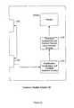
- FIG. 3illustrates a simplified block diagram of an improper speech level sensing circuit.
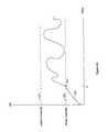
- FIG. 4Aillustrates a graphical representation of an improper speech level at a microphone resulting in a signal level between a noise threshold and an audible threshold.
- FIG. 4Billustrates a graphical representation of a user not talking resulting in a signal level below an ambient noise threshold comprising background noise.
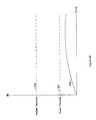
- FIG. 4Cillustrates a graphical representation of proper speech level at a microphone resulting in a signal level above an audible threshold.
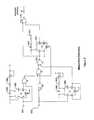
- FIG. 5illustrates a detailed diagram of improper speech level detection circuitry according to the present invention.
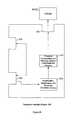
- FIG. 6illustrates a general flow diagram for sensing an improper speech level at a microphone on a headset.
- FIG. 7illustrates a specific flow diagram showing a first method for sensing and indicating an improper speech level at a microphone on a headset.
- the present inventionis directed towards a talker-side device that measures the strength of a voice signal from a microphone.
- the microphonemay be positioned on an adjustable or fixed arm on a communications headset or in a telephone handset. Additionally, the present invention may operate on a PA system comprising a microphone or any other device requiring a microphone to be properly positioned in relation to a talker's mouth.
- a PA systemcomprising a microphone or any other device requiring a microphone to be properly positioned in relation to a talker's mouth.
- the present invention's systems and methodsshould not be limited to this embodiment. Rather, the present invention may operate in relation to any communication device requiring a speech level above a particular threshold at a microphone. As best shown in FIG. 1 , one embodiment of the present invention is used within a telephone headset system.
- a telephone headset systemgenerally comprises a headset 120 , a telephone adapter 105 , and a telephone 100 as well as connections between the devices.
- the headset 120includes a speaker 140 that is placed near the ear of a headset user.
- a headband 125is used to hold the speaker against a user's ear, though in other embodiments, earbud or earhook headsets may also be used.
- a microphone 130is attached to the end of an arm 135 and the arm is coupled to the headband 125 .
- This arm 135may be adjustably mounted on the headband 125 so that the position of the microphone 130 can be moved. This feature allows the headset to fit many different people because the adjustable microphone may be correctly positioned relative to a user's mouth.
- the headset 120may be electrically coupled to a headset adapter 105 via line 110 .
- the headset adapter 105receives a signal from the microphone 130 on the headset 120 and transmits a signal to the speaker 140 on the headset 120 . It is important to note that these signals may be transmitted wirelessly by transceivers on both the headset 120 and headset adapter 105 , and hence line 110 should be understood to include either a wire connection or a wireless connection, e.g., radio, infrared In any event, a signal from the microphone representative of a user's voice is transmitted from the headset 120 to the headset adapter 105 .
- the headset adapter 105is also electrically coupled to a telephone 100 . Therefore, the headset adapter 105 functions as an interface between the telephone 100 and the telephone headset 120 . Additionally, the headset adapter 105 may have other functions such as operating as a switch between the telephone headset 120 and a handset on the telephone 100 .
- FIG. 2Ashows a first embodiment of the present invention functioning within a telephone adapter 105 .
- a telephone adapter 105contains at least two interfaces.
- a first interface 220connects a telephone headset 120 to amplification, rectification and envelope detection circuitry 215 within the telephone adapter 105 .
- An example of a first interface 220is a telephone jack that allows a telephone headset line to plug into the telephone adapter 105 and communicate with the amplification, rectification and envelope detection circuitry 215 .
- the first interface 220may include other types of connection interfaces that allow data to be transmitted between the telephone headset 120 and the telephone adapter 105 such as a wireless transceiver.
- the first interface 220is also coupled to a second interface 225 that connects the telephone adapter 105 to the telephone 100 . This second interface 225 is generally a telephone jack or other hard-wire connection.
- the amplification, rectification and envelope detection circuitry 215comprises a buffer amplifier, a full-wave rectifier and a precision envelope detector and is coupled to threshold comparators and improper speech level detection circuitry 210 .
- This amplification, rectification and envelope detection circuitry 215receives a voice signal from the telephone headset 120 via the first interface and outputs a speech envelope signal representative of the voice signal. This speech envelope signal may then be analyzed to determine whether a telephone headset user is talking and whether the voice signal level is sufficiently high.
- the threshold comparators and improper speech level circuitry 210compares the speech envelope signal to two thresholds. These comparisons are typically done in parallel but may also be done sequentially. This signal is compared to an average noise threshold in order to determine whether a voice signal from the microphone is present. The signal is also compared to a desired audible level threshold in order to determine whether the speech envelope has achieved desired speech peak indicative of a voice signal level necessary for proper communication. These comparators output pulses indicating whether the speech envelope level and corresponding speech peaks is above or below their corresponding thresholds. The pulses are input in logic within the threshold comparators and improper speech level detection circuitry 210 and a signal is output indicating whether a user is talking and a voice signal is too weak. This output signal is transmitted to an indicator 205 ( a ).
- the indicatornotifies a telephone headset user that the voice signal at the microphone is not sufficiently strong (i.e. a low signal-to-noise ratio).
- the indicator 205 ( a )may be part of the adapter 105 , such as a visual indicator like a light emitting diode (LED), or an auditory indicator, such as a speaker that generates an audible tone.
- the indicator 205 ( a )maybe coupled to the receive lines of the headset speaker, so that the generated tone indicating improper speech level is output in the headset speaker, and heard directly by the user.
- a low signal-to-noise ratiomay be indicative of problems other than a mispositioned microphone. For example, a user may be talking too softly into the microphone.
- the indicator 205 ( a )also serves as a general warning indicator representative of the signal at the microphone. Therefore, after perceiving the activated indicator 205 ( a ) (e.g., seeing a light or hearing a tone), the user can re-position the microphone and/or talk louder so as to increase a corresponding signal-to-noise ratio.
- FIG. 2Bshows a second embodiment of the present invention whereby an indicator 205 ( b ) is external to the telephone adapter 105 .
- the telephone adapter 105includes a third interface 230 .
- the third interface 230couples the external indicator 205 ( b ) to the improper speech level detection circuitry 210 within the telephone adapter 105 .
- Examples of the third interface 230include a fixed line connection whereby the external indicator 205 b is electrically coupled to the improper speech level detection circuitry 210 , and a plug in jack (e.g., mini- 8 ) whereby the indicator 205 ( b ) may be attached or removed by connecting a plug into the third interface 230 .
- the third interface 230may be a transceiver that transmits a wireless signal to the external indicator 205 ( b ).
- the threshold comparators and the improper speech level detection circuitry 210activates the external indicator 205 ( b ) via the third interface 230 .
- the external indicatorinclude a light (e.g., LED) positioned on a stand, a light positioned on the telephone headset, or a tone generator (e.g., speaker).
- the external positioning of the indicator 205 ballows a user to select a particular indicator as well as allowing a vendor the option of selling the indicators as “plug-in” modules to the headset adapter.
- An example of a “plug-in” moduleis described in U.S. patent application, Ser. No. 09/401,070, entitled “Accessory Interface Bus For Telephone Headset Adapter, filed Sep. 22, 1999, the disclosure of which is incorporated herein by reference.
- FIG. 3shows a simplified block diagram of the improper speech level detection circuitry.
- This circuitrycomprises four stages: a power supply and input buffer stage 305 , a rectification and envelope detection stage 310 , a threshold adjust and compare stage 315 , and a misposition detection stage 320 .
- An audio inputis coupled to the power supply and input buffer stage 305 and receives a signal from the telephone headset 120 .
- the power supply and input buffer stage 305includes a buffer amplifier 325 with a predefined gain. In this embodiment, the gain is set at 20 dB.
- the amplifier 325receives a signal from the audio input, applies a gain to the signal, and transmits the signal to the rectification and envelope detection stage 310 .
- the rectification and envelope detection stage 310comprises a full-wave rectifier 330 and a precision envelope detector 335 .
- the amplified signal received from the power supply and input buffer stage 305is transmitted to the full-wave rectifier 330 .
- the full-wave rectifier 330converts the amplified signal to an average direct current signal representative of the instantaneous magnitude of the amplified signal.
- the rectified signalis then transmitted to the precision envelope detector 335 .
- the precision envelope detector 335converts the rectified instantaneous magnitude into a short-term average magnitude representing the speech envelope. This conversion by the precision envelope detector 335 allows independent control of the attack and decay characteristics of the rectified signal.
- the speech envelope signalis transmitted to the threshold adjust and compare stage 315 .
- the threshold adjust and compare stage 315comprises two comparators.
- a first comparator 345determines whether the speech envelope level is above a background noise threshold.
- a second comparator 340determines whether voice peak levels in the speech envelope cross an audible threshold level required for proper communication. As mentioned above, these comparisons are typically done in parallel but may also be done sequentially.
- the background noise thresholdtypically represents the ambient noise level of the environment in which the telephone headset or communications device operates.
- a background noise threshold for a communications device operating on a warehouse flooris generally higher than a threshold for a communications device used in an office.
- This background noise thresholdmay be fixed or may be dynamically adjusted as the ambient noise changes.
- An embodimentmay include a plurality of fixed background noise thresholds.
- a switch or keyboardallows a user to select a specific background noise threshold depending on the environment in which the communication device is being used.
- Another embodimentmay provide an adaptive background noise threshold that dynamically adjusts to a particular environment.
- a method in which the background noise threshold may be dynamically adjustedcomprises monitoring a signal received by the communications device.
- this received signalis active (i.e., a person on the other side of the conversation is speaking) and the signal from the communication device is relatively low (i.e., indicative of a person listening), then the signal from the communication device likely represents the ambient noise of the environment in which the communication device is operating. The level of this signal may then be used to set a relatively accurate noise threshold level.
- the speech envelopeis received from the rectification and envelope detection stage 310 and compared to the background noise threshold by the first comparator 345 . If the speech envelope level is above the noise threshold then the comparator outputs a logical TRUE (e.g., +5 V). This output indicates that a user is speaking into the telephone headset or communication device.
- the background noise thresholdis usually slightly above the ambient noise level in order to minimize erroneous TRUE outputs caused by sudden loud noises. Note that for a noise-canceling microphone this level is significantly lower than for an omni-directional microphone with the same sensitivity to the user's voice. It is particularly important that the background noise threshold be set as low as possible for noise-canceling microphones since positioning errors cause a more rapid loss of sensitivity to the user's voice and detection of the user's voice is necessary for the proper operation of the circuit.
- the audible thresholdtypically represents a required voice signal level required for proper communication. For example, a microphone within a telephone headset requires that a user's voice be at a minimum decibel level in order for a person on the other side of a conversation to be able to easily hear what is being said. Although this threshold may vary depending on the specific communication device that is used, the threshold is generally fixed and infrequently adjusted.
- the speech envelopeis received from the rectification and envelope detection stage 310 and speech peaks within the speech envelope are monitored by the second comparator 340 to determine whether they cross the audible threshold. If these speech peaks cross the audible threshold then the second comparator 340 outputs a logical FALSE (e.g., 0 V).
- This outputindicates that the voice signal is sufficiently strong at a microphone in a telephone headset or communication device. However, while the level of the speech envelope, including speech peaks therein, remains below the audible threshold, then the second comparator 340 outputs a logical TRUE.
- Both outputsare transmitted to the misposition detection stage 320 comprising a first retriggerable monostable 350 , a non-retriggerable monostable 355 , a second retriggerable monostable 365 , and various logic gates.
- the misposition detection stage 320receives the outputs from the first comparator 345 and the second comparator 340 and determines whether a voice signal is not sufficiently strong at a microphone in a telephone headset or communication device.
- a normal speech envelopetakes time to develop to its peak amplitude. If a simple “AND” function is used to identify a weak voice signal, a temporary misposition or improper speech level indication will occur before the audible threshold is reached, be interrupted by the signal from the second comparator 340 , then will resume as the envelope decays toward the noise threshold. In addition, the indicator 380 will flash only for the interval that the signal exceeds the noise threshold and be blanked only for the time it is actively above the audible threshold. For very low speech or severe mispositioning these flashes may be too brief to be obvious. While transient outputs of the AND gate for low level speech could be stretched, the transient outputs during the attack and decay of normal speech would also be stretched, giving steady false indications for all normal speech.
- the non-retriggerable monostable 355is provided to inhibit an improper speech level or microphone misposition indication for a period of time required by a speech envelope to develop and reach the audible threshold.
- the non-retriggerable monostable 355may suppress an indication for 100 ms allowing the speech envelope to reach the audible threshold. After this interval, if the signal is still between the two thresholds, an indication is activated showing that the audible threshold has not been exceeded for a certain period of time by various peaks within the speech envelope. This process will be described in greater detail below.
- the dynamics of speechare such that extreme variation in momentary speech level exists even within speech that is perceived overall to be normal in level.
- the duration and interval between speech peaksvaries inversely with their intensity, which means that the higher the audible threshold is set, the less frequently it will be exceeded.
- speechis found between these speech peaks and the speech between the peaks is of insufficient strength to prevent false misposition or improper speech level indications. This requires that the inhibiting effect of the peaks be set to at least extend over the duration of the decay of the envelope of a phoneme. In practice it was found that even significantly mispositioned microphones would exhibit enough peaks to limit the usefulness of the display if the threshold and time constant were set low enough to be treated on a phoneme basis.
- the first retriggerable monostable 350is implemented to set the amount of time before another speech peak is expected to cross the audible threshold. Since speech peaks are only expected to cross the audible threshold occasionally, and speech between thresholds is expected to be present over most of that interval, it is necessary to inhibit the improper speech level indication until the next peak is overdue. The amount of time is dependent on the level selected for the audible threshold since detection using lower thresholds can be expected to occur more frequently. For example, the first retriggerable monostable 350 may provide a 3 second time constant during which the output of an improper speech level indication is prevented, even if there is detected speech above the background noise threshold and below the audible threshold. Speech peaks within the speech envelope signal that cross the audible threshold will reset the improper speech level indicator 380 , terminating any activated improper speech level indication and preventing any new indication for an established duration of time relative to the time constant. This process will be described in more detail below.
- the second retriggerable monostable 365provides a minimum duration for which the indicator 380 is activated. This second monostable 365 prevents the indicator 380 from flickering on and off, and also ensures that the indicator 380 is turned on a sufficient duration so that a user will notice the indication. For example, the second monostable 365 may require that an initiated indication stay on for a minimum time period of 1 second. If the voice signal remains weak during this interval the indication will persist without interruption.
- An AND gate 360has inputs coupled to the first retriggerable monostable 350 , the second comparator 345 , and the non-retriggerable monostable 355 .
- the AND gate 360will output a logical TRUE when a detected voice signal is too weak and the inverted pulse from the non-retriggerable monostable 355 has passed (i.e., the initial time delay is complete).
- An OR gate 370has inputs coupled to the AND gate 360 output and the second retriggerable monostable 365 .
- the output of the OR gate 370is coupled to the indicator 380 and turns it on if either input is high.
- the indicator 380is activated.
- the indicator 380may be visual (e.g., an LED) or auditory (e.g., a beep).
- FIG. 4Ais a graphical representation of a weak voice signal at a microphone within a telephone headset or communication device that is detected by various embodiments of the present invention.
- a noise threshold 400is shown at a particular decibel (dB) level.
- An audible threshold 410is shown at another particular dB level.
- a speech envelope level 430is shown tracing a generic speech pattern 430 .
- the speech pattern 430crosses the noise threshold 400 .
- the output on the first comparator 345will go high indicating that a user is talking.
- the non-retriggerable monostable 355will output an inverted pulse suppressing a microphone misposition or improper speech level indication for a period of time required for the speech envelope to develop.
- the second comparator 340will be high indicating that a speech peak has not crossed the audible threshold and will remain high until a speech peak crosses this threshold.
- the first retriggerable monostable 350 outputwill remain high (presuming that it had not been activated by a previous speech peak), enabling the indicator 380 to activate after the initial suppression time period has passed.
- the speech peaks within the speech envelopedo not cross the audible threshold 410 , but remain between the noise threshold 400 and the audible threshold 410 .
- the indicator 380will be activated after the initial suppression time has passed since the output on the first comparator 345 remains high.
- FIG. 4Bis a graphical representation of a non-talking event that is detected by various embodiments of the present invention.
- the noise threshold 400is shown at a particular dB level, and the audible threshold 410 is shown at another particular dB level.
- a speech envelope 430is shown tracing a generic speech pattern 430 .
- the speech envelope 430does not cross the noise threshold 400 .
- the output on the first comparator 345remains low. This low output drives the output on the AND gate 360 to low resulting in the indicator 380 never being activated.
- FIG. 4Cis a graphical representation of a voice signal of sufficient strength at a microphone on a telephone headset or other communication device that is detected by embodiments of the present invention.
- a speech envelope 430is shown tracing a generic speech pattern.
- the speech envelope 430crosses the noise threshold 400 .
- the first comparator 345goes high while the second comparator 340 remains high.
- the non-retriggerable monostable 355suppresses an initial microphone misposition or improper speech level indication until the speech envelope can develop.
- the speech envelope 430crosses the audible threshold 410 .
- This second point of timeoccurs before the indication suppression time has expired so there has not been a indication prior to the second point of time t 3 .
- the second comparator 340goes low causing the first retriggerable monostable 350 to output an inverted pulse of a certain time period. This pulse will drive the output on the AND gate 360 to zero and prevent any indication.
- another speech peak within the speech envelopeneeds to cross the audible threshold 410 within the time period of this pulse in order to prevent a indication.
- a second speech peak 460crosses the audible threshold 410 before the pulse time period expires. The time remaining before the pulse will end is reset to the time period of the pulse.
- the indicator 380is not activated between the two speech peaks even though the speech envelope drops below the audible threshold 410 during this time interval.
- FIG. 5is a detailed diagram of the misposition detection stage circuitry 320 .
- the non-retriggerable monostable 355has an input that receives the first comparator's output 505 .
- the non-retriggerable monostable 355is also coupled to a first RC circuit comprising a capacitor 540 and at least one resistor 545 .
- the time constant on the inverted pulse generated by the non-retriggerable monostable 355is equal to the time constant of a first attached RC circuit which is the capacitance of the first capacitor 540 multiplied by the effective resistance of the at least one resistor 545 .
- the non-retriggerable monostable 355is activated when the first comparator 345 determines that the speech envelope level has crossed the noise threshold. Once activated, the non-triggerable monostable 355 outputs a single inverted pulse with a corresponding time constant. This inverted pulse is transmitted to the AND gate 360 and drives the output on the AND gate 360 to low. As a result, a microphone misposition or improper speech level indication is inhibited for a period of time equal to the time constant on the non-retriggerable monostable 355 .
- the first retriggerable monostable 350has an input that receives the second comparator's output 507 .
- the first retriggerable monostable 350is coupled to a second RC circuit comprising a second capacitor 525 and at least one resistor 530 .
- the time constant on the inverted pulse generated by the first retriggerable monostable 350is equal to the time constant of the second RC circuit. For example, if a desired time constant of the inverted pulse is 3 s, then a 1 ⁇ F capacitor and an effective resistance of 3 M ⁇ would provide the desired time constant.
- the first retriggerable monostable 350is activated when the second comparator 340 determines that a speech peak of the speech envelope signal has crossed the audible threshold.
- the first retriggerable monostable 350outputs a single inverted pulse with the corresponding time constant.
- An additional speech peak crossing the audible threshold as the pulse is being transmittedwill retrigger the monostable 350 .
- This new triggerre-starts the time period from zero, thereby extending the length of the inverted pulse.
- the inverted pulsemay continue as long as the first retriggerable monostable 350 is retriggered within its corresponding time constant.
- This inverted pulseis transmitted to the AND gate 360 and a reset on the second retriggerable monostable 365 .
- the output on the AND gate 360is driven low as long as a speech peak crosses the audible threshold within the time constant of the first retriggerable monostable 350 .
- the output on the first retriggerable monostable 350goes high and allows the output on the AND gate 360 to go high unless the output on the non-retriggerable monostable 355 is suppressing the indicator 380 or the first comparator 345 has already gone low.
- the second retriggerable monostable 365is coupled to the output of the AND gate 360 and its reset is coupled to the output of the first retriggerable monostable 350 .
- the second retriggerable monostable 365provides a minimum time period for which the indicator 380 is activated. This time period is equal to the time constant of the attached third RC circuit comprising a third capacitor 550 and a third resistor 555 .
- the time constant on the pulse generated by the second retriggerable monostable 365is equal to the time constant of the third RC circuit. For example, if a desired time constant of the pulse is 1 s, then a 1 ⁇ F capacitor and an effective resistance of 1 M ⁇ would provide the desired time constant.
- the second retriggerable monostable 365is activated when the output on the AND gate 360 is high. Once activated, the second retriggerable monostable 365 outputs a single pulse with the corresponding time constant. This pulse is transmitted to an OR gate 370 driving the output of the OR gate high for at least the time duration of the pulse's time constant.
- the OR gate 370is also connected directly to the output of the AND gate 360 so that the output will remain high even after the pulse from the second retriggerable monostable 365 has expired should the output of the first comparator 505 remain high while the output of the second comparator 507 also remains high.
- the pulsemay continue as long as the second retriggerable monostable is retriggered within its corresponding time constant.
- an indicationis activated any time the output of the AND gate 360 goes high (i.e. the voice signal is between the two thresholds) and the minimum time period of the activated indication is controlled by the time constant of the second retriggerable monostable 365 (providing that it is not terminated by the first retriggerable monostable 350 ).
- the second retriggerable monostable's reset inputis coupled to the output of the first retriggerable monostable 350 . Should the first retriggerable monostable 350 go active, the second monostable 365 will be reset, terminating any existing pulse and preventing any new pulse for as long as the reset remains low.
- FIG. 6shows a simplified flowchart describing a method for sensing a voice signal level at a microphone on a telephone headset.
- This methodmay be implemented by the foregoing described hardware, or its equivalents, or by a digital signal processor (DSP) suitably programmed.
- DSPdigital signal processor
- a signalis generated at the microphone and transmitted to the sensing device.
- the sensing devicereceives 600 the signal and determines whether the signal is sufficiently strong.
- the signal levelis compared 605 to a noise threshold to determine whether a headset user is talking.
- the signal levelis also compared 610 to an audible threshold to determine whether the signal is sufficiently strong to provide quality reception at the other end of the telephone call.
- the comparisonsare analyzed 620 to determine whether (1) the user is talking and (2) the voice signal is too weak. If the user is talking and the voice signal is too weak, then an indicator is activated 630 . Typically, this indication is caused by the microphone on the headset being mispositioned. The indicator is activated for a period of time and then the method restarts 635 . However, if the headset user is not talking or the voice signal is sufficiently strong, then the indicator is not activated and the method restarts 625 .
- FIG. 7shows a detailed flowchart of a method for detecting and indicating a weak voice signal at a microphone in a telephone headset or other communication device.
- this methodmay be implemented by the foregoing described hardware, or its equivalents, or by a digital signal processor (DSP) suitably programmed. Additionally, the method is depicted as having multiple steps performed in parallel; however, the steps may also be performed sequentially.
- DSPdigital signal processor
- a signalis generated at a microphone and transmitted to an amplifier 700 .
- the amplified signalis converted 705 to a speech envelope using a full-wave rectifier and precision envelope detector.
- the full-wave rectifierconverts the amplified signal to a unipolar signal representing the instantaneous magnitude of the amplified signal.
- the precision envelope detectorconverts the instantaneous magnitude of the rectified signal to a short-term average magnitude, thereby creating the speech envelope.
- This speech envelopeis compared to first threshold to determine whether speech is present in the signal from the microphone and to a second threshold in order to determine whether the strength of the signal at the microphone is sufficiently strong to enable proper communication.
- the speech envelope levelis compared 710 to a noise threshold representing average ambient noise of the environment in which the microphone is operating. This comparison determines whether a user is talking. If the speech envelope level is above the noise threshold 715 , the length of time that it has been above the threshold is compared to a defined time interval (called X in the diagram). If the signal is above the noise threshold and that interval of time has passed since it crossed the noise threshold, the other conditions for misposition or improper speech level indication will be evaluated. If either condition is false, input monitoring will continue. The time interval (X) from the time when the signal crosses the threshold prevents false indications by ignoring noise peaks and giving the speech peaks within the speech envelope time to develop before an indication is generated. If the speech envelope level remains below the noise threshold then condition 715 remains false, further evaluation does not occur and input monitoring continues.
- a noise thresholdrepresenting average ambient noise of the environment in which the microphone is operating. This comparison determines whether a user is talking. If the speech envelope level is above the noise threshold 715 , the length of time that it has been
- speech peaks within speech envelopeare compared 720 to an audible threshold representing a speech level required at the microphone for proper communication. This comparison determines whether a microphone is mispositioned, a user is speaking too softly, or other causes of a weak voice signal at the microphone. If a speech peak crosses the audible threshold then a misposition indication is suppressed for a period of time (Y). If an additional speech peak crosses the audible threshold during this suppression period, the period of time is re-initialized to zero 725 .
- an indicator 380is activated 730 , for a minimum length of time (Z) determined by condition 735 . Should a speech peak cross the audible threshold while the indicator 380 is active, the indication will be deactivated 740 until the conditions 715 and 725 both evaluate to true.
- the inventionmay be embodied in other specific forms without departing from the spirit or essential characteristics thereof.
- the particular division of functionality between the various modules, circuits, or componentsmay differ from that described herein, given the variety of software hardware platforms that may be used to practice the invention.
- the hardware implementationsinclude custom ASICs, discrete logic, FPGAs, PLAs, or DSP with appropriate software programming.
- the particular naming of the circuit elementsis not mandatory or significant, and the mechanisms that implement the invention or its features may have different names or formats. Accordingly, the disclosure of the present invention is intended to be illustrative, but not limiting, of the scope of the invention, which is set forth in the following claims.
Landscapes
- Engineering & Computer Science (AREA)
- Signal Processing (AREA)
- Telephone Function (AREA)
Abstract
Description
Claims (29)
Priority Applications (3)
| Application Number | Priority Date | Filing Date | Title |
|---|---|---|---|
| US09/952,434US6941161B1 (en) | 2001-09-13 | 2001-09-13 | Microphone position and speech level sensor |
| US10/940,130US7133701B1 (en) | 2001-09-13 | 2004-09-13 | Microphone position and speech level sensor |
| US11/594,344US7457644B1 (en) | 2001-09-13 | 2006-11-07 | Microphone position and speech level sensor |
Applications Claiming Priority (1)
| Application Number | Priority Date | Filing Date | Title |
|---|---|---|---|
| US09/952,434US6941161B1 (en) | 2001-09-13 | 2001-09-13 | Microphone position and speech level sensor |
Related Child Applications (1)
| Application Number | Title | Priority Date | Filing Date |
|---|---|---|---|
| US10/940,130DivisionUS7133701B1 (en) | 2001-09-13 | 2004-09-13 | Microphone position and speech level sensor |
Publications (1)
| Publication Number | Publication Date |
|---|---|
| US6941161B1true US6941161B1 (en) | 2005-09-06 |
Family
ID=34887894
Family Applications (3)
| Application Number | Title | Priority Date | Filing Date |
|---|---|---|---|
| US09/952,434Expired - LifetimeUS6941161B1 (en) | 2001-09-13 | 2001-09-13 | Microphone position and speech level sensor |
| US10/940,130Expired - LifetimeUS7133701B1 (en) | 2001-09-13 | 2004-09-13 | Microphone position and speech level sensor |
| US11/594,344Expired - LifetimeUS7457644B1 (en) | 2001-09-13 | 2006-11-07 | Microphone position and speech level sensor |
Family Applications After (2)
| Application Number | Title | Priority Date | Filing Date |
|---|---|---|---|
| US10/940,130Expired - LifetimeUS7133701B1 (en) | 2001-09-13 | 2004-09-13 | Microphone position and speech level sensor |
| US11/594,344Expired - LifetimeUS7457644B1 (en) | 2001-09-13 | 2006-11-07 | Microphone position and speech level sensor |
Country Status (1)
| Country | Link |
|---|---|
| US (3) | US6941161B1 (en) |
Cited By (38)
| Publication number | Priority date | Publication date | Assignee | Title |
|---|---|---|---|---|
| US20040059578A1 (en)* | 2002-09-20 | 2004-03-25 | Stefan Schulz | Method and apparatus for improving the quality of speech signals transmitted in an aircraft communication system |
| US20040162722A1 (en)* | 2001-05-22 | 2004-08-19 | Rex James Alexander | Speech quality indication |
| US20040242160A1 (en)* | 2003-05-30 | 2004-12-02 | Nokia Corporation | Mobile phone for voice adaptation in socially sensitive environment |
| US20050047605A1 (en)* | 2003-09-03 | 2005-03-03 | Monster, Llc | Audio power monitoring system |
| US20050282592A1 (en)* | 2004-06-21 | 2005-12-22 | Frerking Melvin D | Hands-free conferencing apparatus and method for use with a wireless telephone |
| US20070032259A1 (en)* | 2005-08-05 | 2007-02-08 | George Gounaris | Method and apparatus for voice amplitude feedback in a communications device |
| US7609784B1 (en)* | 2004-04-26 | 2009-10-27 | Dgi Creations, Llc | Signal decoding method and apparatus with dynamic noise threshold |
| US20090281809A1 (en)* | 2008-05-09 | 2009-11-12 | Plantronics, Inc. | Headset Wearer Identity Authentication With Voice Print Or Speech Recognition |
| US20100020940A1 (en)* | 2008-07-28 | 2010-01-28 | Broadcom Corporation | Far-end sound quality indication for telephone devices |
| US20100167783A1 (en)* | 2008-12-31 | 2010-07-01 | Motorola, Inc. | Portable Electronic Device Having Directional Proximity Sensors Based on Device Orientation |
| WO2010077550A3 (en)* | 2008-12-29 | 2010-09-10 | Motorola, Inc. | Portable electronic device having self-calibrating proximity sensors |
| US20100254496A1 (en)* | 2009-04-06 | 2010-10-07 | Guo-Hau Gau | Noise power estimation method and device thereof |
| US20100271331A1 (en)* | 2009-04-22 | 2010-10-28 | Rachid Alameh | Touch-Screen and Method for an Electronic Device |
| US20100271312A1 (en)* | 2009-04-22 | 2010-10-28 | Rachid Alameh | Menu Configuration System and Method for Display on an Electronic Device |
| US20100295773A1 (en)* | 2009-05-22 | 2010-11-25 | Rachid Alameh | Electronic device with sensing assembly and method for interpreting offset gestures |
| US20100295772A1 (en)* | 2009-05-22 | 2010-11-25 | Alameh Rachid M | Electronic Device with Sensing Assembly and Method for Detecting Gestures of Geometric Shapes |
| US20100299390A1 (en)* | 2009-05-22 | 2010-11-25 | Rachid Alameh | Method and System for Controlling Data Transmission to or From a Mobile Device |
| US20100297946A1 (en)* | 2009-05-22 | 2010-11-25 | Alameh Rachid M | Method and system for conducting communication between mobile devices |
| US20100294938A1 (en)* | 2009-05-22 | 2010-11-25 | Rachid Alameh | Sensing Assembly for Mobile Device |
| US20100299642A1 (en)* | 2009-05-22 | 2010-11-25 | Thomas Merrell | Electronic Device with Sensing Assembly and Method for Detecting Basic Gestures |
| US20100295781A1 (en)* | 2009-05-22 | 2010-11-25 | Rachid Alameh | Electronic Device with Sensing Assembly and Method for Interpreting Consecutive Gestures |
| US20110006190A1 (en)* | 2009-07-10 | 2011-01-13 | Motorola, Inc. | Devices and Methods for Adjusting Proximity Detectors |
| US20110115711A1 (en)* | 2009-11-19 | 2011-05-19 | Suwinto Gunawan | Method and Apparatus for Replicating Physical Key Function with Soft Keys in an Electronic Device |
| US20110148752A1 (en)* | 2009-05-22 | 2011-06-23 | Rachid Alameh | Mobile Device with User Interaction Capability and Method of Operating Same |
| US20130163775A1 (en)* | 2011-12-23 | 2013-06-27 | Paul G. Yamkovoy | Communications Headset Speech-Based Gain Control |
| US20130219525A1 (en)* | 2012-02-16 | 2013-08-22 | Aviv Soffer | Secure audio peripheral device |
| CN103329065A (en)* | 2011-01-14 | 2013-09-25 | 高通股份有限公司 | Dynamic DC-offset determination for proximity sensing |
| US20140056439A1 (en)* | 2012-08-23 | 2014-02-27 | Samsung Electronics Co., Ltd. | Electronic device and method for selecting microphone by detecting voice signal strength |
| US8751056B2 (en) | 2010-05-25 | 2014-06-10 | Motorola Mobility Llc | User computer device with temperature sensing capabilities and method of operating same |
| US8963885B2 (en) | 2011-11-30 | 2015-02-24 | Google Technology Holdings LLC | Mobile device for interacting with an active stylus |
| US8963845B2 (en) | 2010-05-05 | 2015-02-24 | Google Technology Holdings LLC | Mobile device with temperature sensing capability and method of operating same |
| US9063591B2 (en) | 2011-11-30 | 2015-06-23 | Google Technology Holdings LLC | Active styluses for interacting with a mobile device |
| US9103732B2 (en) | 2010-05-25 | 2015-08-11 | Google Technology Holdings LLC | User computer device with temperature sensing capabilities and method of operating same |
| US9749733B1 (en)* | 2016-04-07 | 2017-08-29 | Harman Intenational Industries, Incorporated | Approach for detecting alert signals in changing environments |
| US9900735B2 (en) | 2015-12-18 | 2018-02-20 | Federal Signal Corporation | Communication systems |
| US11315564B2 (en)* | 2019-03-13 | 2022-04-26 | Jvckenwood Corporation | Wireless device |
| US12183341B2 (en) | 2008-09-22 | 2024-12-31 | St Casestech, Llc | Personalized sound management and method |
| US12249326B2 (en) | 2007-04-13 | 2025-03-11 | St Case1Tech, Llc | Method and device for voice operated control |
Families Citing this family (4)
| Publication number | Priority date | Publication date | Assignee | Title |
|---|---|---|---|---|
| US8195095B2 (en)* | 2006-05-19 | 2012-06-05 | International Business Machines Corporation | Mitigating audible acknowledgement volume in a vehicle security system |
| US20070293270A1 (en)* | 2006-06-20 | 2007-12-20 | Franco Montebovi | Voice acceptance of incoming call without voice recognition |
| US7996048B1 (en) | 2006-12-22 | 2011-08-09 | At&T Mobility Ii Llc | Enhanced call reception and privacy |
| US9913059B2 (en) | 2016-02-23 | 2018-03-06 | Plantronics, Inc. | Headset position sensing, reporting, and correction |
Citations (19)
| Publication number | Priority date | Publication date | Assignee | Title |
|---|---|---|---|---|
| US4327252A (en) | 1980-02-08 | 1982-04-27 | Tomatis Alfred A A A | Apparatus for conditioning hearing |
| US4677678A (en) | 1984-07-10 | 1987-06-30 | The United States Of America As Represented By The Department Of Health And Human Services | Active hearing protectors |
| US4777649A (en) | 1985-10-22 | 1988-10-11 | Speech Systems, Inc. | Acoustic feedback control of microphone positioning and speaking volume |
| US4928307A (en) | 1989-03-02 | 1990-05-22 | Acs Communications | Time dependent, variable amplitude threshold output circuit for frequency variant and frequency invariant signal discrimination |
| US5070527A (en) | 1989-03-02 | 1991-12-03 | Acs Communications, Inc. | Time dependant, variable amplitude threshold output circuit for frequency variant and frequency invarient signal discrimination |
| US5091954A (en) | 1989-03-01 | 1992-02-25 | Sony Corporation | Noise reducing receiver device |
| US5303308A (en) | 1992-07-07 | 1994-04-12 | Gn Netcom A/S | Audio frequency signal compressing system |
| US5355418A (en) | 1992-10-07 | 1994-10-11 | Westinghouse Electric Corporation | Frequency selective sound blocking system for hearing protection |
| US5426719A (en) | 1992-08-31 | 1995-06-20 | The United States Of America As Represented By The Department Of Health And Human Services | Ear based hearing protector/communication system |
| US5692017A (en) | 1994-07-20 | 1997-11-25 | Nec Corporation | Receiving circuit |
| US5717818A (en)* | 1992-08-18 | 1998-02-10 | Hitachi, Ltd. | Audio signal storing apparatus having a function for converting speech speed |
| US5894513A (en) | 1995-04-19 | 1999-04-13 | Nec Corporation | Hands-free communication unit having residual acoustic echo suppression means for suppressing residual echoes which have been left unremoved by an echo canceller, a bilateral communication system and a method for suppressing residual echoes |
| US6094490A (en) | 1996-11-27 | 2000-07-25 | Lg Semicon Co., Ltd. | Noise gate apparatus for digital audio processor |
| US6118878A (en) | 1993-06-23 | 2000-09-12 | Noise Cancellation Technologies, Inc. | Variable gain active noise canceling system with improved residual noise sensing |
| US20020068537A1 (en)* | 2000-12-04 | 2002-06-06 | Mobigence, Inc. | Automatic speaker volume and microphone gain control in a portable handheld radiotelephone with proximity sensors |
| US20020094845A1 (en)* | 2001-01-16 | 2002-07-18 | Rei Inasaka | Body worn display system |
| US20030002688A1 (en)* | 2001-06-27 | 2003-01-02 | International Business Machines Corporation | Volume regulating and monitoring system |
| US6542735B1 (en)* | 1999-11-15 | 2003-04-01 | Worldcom, Inc. | Method of setting security codes in a cordless telephone system with multiple communication devices |
| US6801611B2 (en)* | 2001-06-29 | 2004-10-05 | Callpod, Inc. | Call pod for having conference calls in a portable environment |
Family Cites Families (11)
| Publication number | Priority date | Publication date | Assignee | Title |
|---|---|---|---|---|
| US4013962A (en)* | 1975-08-14 | 1977-03-22 | Motorola, Inc. | Improved receiver selecting (voting) system |
| CA2040025A1 (en)* | 1990-04-09 | 1991-10-10 | Hideki Satoh | Speech detection apparatus with influence of input level and noise reduced |
| JPH05130067A (en)* | 1991-10-31 | 1993-05-25 | Nec Corp | Variable threshold level voice detector |
| JP2684300B2 (en)* | 1992-10-13 | 1997-12-03 | ローム株式会社 | Mobile communication telephone and silent section detection circuit |
| KR970017456A (en)* | 1995-09-30 | 1997-04-30 | 김광호 | Silent and unvoiced sound discrimination method of audio signal and device therefor |
| FI104872B (en)* | 1997-04-11 | 2000-04-14 | Nokia Networks Oy | A method for controlling load on a mobile communication system |
| JP3597671B2 (en)* | 1997-05-16 | 2004-12-08 | 三菱電機株式会社 | Handsfree phone |
| US5867574A (en)* | 1997-05-19 | 1999-02-02 | Lucent Technologies Inc. | Voice activity detection system and method |
| US6385548B2 (en)* | 1997-12-12 | 2002-05-07 | Motorola, Inc. | Apparatus and method for detecting and characterizing signals in a communication system |
| US6397050B1 (en)* | 1999-04-12 | 2002-05-28 | Rockwell Collins, Inc. | Multiband squelch method and apparatus |
| US6415029B1 (en)* | 1999-05-24 | 2002-07-02 | Motorola, Inc. | Echo canceler and double-talk detector for use in a communications unit |
- 2001
- 2001-09-13USUS09/952,434patent/US6941161B1/ennot_activeExpired - Lifetime
- 2004
- 2004-09-13USUS10/940,130patent/US7133701B1/ennot_activeExpired - Lifetime
- 2006
- 2006-11-07USUS11/594,344patent/US7457644B1/ennot_activeExpired - Lifetime
Patent Citations (19)
| Publication number | Priority date | Publication date | Assignee | Title |
|---|---|---|---|---|
| US4327252A (en) | 1980-02-08 | 1982-04-27 | Tomatis Alfred A A A | Apparatus for conditioning hearing |
| US4677678A (en) | 1984-07-10 | 1987-06-30 | The United States Of America As Represented By The Department Of Health And Human Services | Active hearing protectors |
| US4777649A (en) | 1985-10-22 | 1988-10-11 | Speech Systems, Inc. | Acoustic feedback control of microphone positioning and speaking volume |
| US5091954A (en) | 1989-03-01 | 1992-02-25 | Sony Corporation | Noise reducing receiver device |
| US4928307A (en) | 1989-03-02 | 1990-05-22 | Acs Communications | Time dependent, variable amplitude threshold output circuit for frequency variant and frequency invariant signal discrimination |
| US5070527A (en) | 1989-03-02 | 1991-12-03 | Acs Communications, Inc. | Time dependant, variable amplitude threshold output circuit for frequency variant and frequency invarient signal discrimination |
| US5303308A (en) | 1992-07-07 | 1994-04-12 | Gn Netcom A/S | Audio frequency signal compressing system |
| US5717818A (en)* | 1992-08-18 | 1998-02-10 | Hitachi, Ltd. | Audio signal storing apparatus having a function for converting speech speed |
| US5426719A (en) | 1992-08-31 | 1995-06-20 | The United States Of America As Represented By The Department Of Health And Human Services | Ear based hearing protector/communication system |
| US5355418A (en) | 1992-10-07 | 1994-10-11 | Westinghouse Electric Corporation | Frequency selective sound blocking system for hearing protection |
| US6118878A (en) | 1993-06-23 | 2000-09-12 | Noise Cancellation Technologies, Inc. | Variable gain active noise canceling system with improved residual noise sensing |
| US5692017A (en) | 1994-07-20 | 1997-11-25 | Nec Corporation | Receiving circuit |
| US5894513A (en) | 1995-04-19 | 1999-04-13 | Nec Corporation | Hands-free communication unit having residual acoustic echo suppression means for suppressing residual echoes which have been left unremoved by an echo canceller, a bilateral communication system and a method for suppressing residual echoes |
| US6094490A (en) | 1996-11-27 | 2000-07-25 | Lg Semicon Co., Ltd. | Noise gate apparatus for digital audio processor |
| US6542735B1 (en)* | 1999-11-15 | 2003-04-01 | Worldcom, Inc. | Method of setting security codes in a cordless telephone system with multiple communication devices |
| US20020068537A1 (en)* | 2000-12-04 | 2002-06-06 | Mobigence, Inc. | Automatic speaker volume and microphone gain control in a portable handheld radiotelephone with proximity sensors |
| US20020094845A1 (en)* | 2001-01-16 | 2002-07-18 | Rei Inasaka | Body worn display system |
| US20030002688A1 (en)* | 2001-06-27 | 2003-01-02 | International Business Machines Corporation | Volume regulating and monitoring system |
| US6801611B2 (en)* | 2001-06-29 | 2004-10-05 | Callpod, Inc. | Call pod for having conference calls in a portable environment |
Cited By (71)
| Publication number | Priority date | Publication date | Assignee | Title |
|---|---|---|---|---|
| US20040162722A1 (en)* | 2001-05-22 | 2004-08-19 | Rex James Alexander | Speech quality indication |
| US20040059578A1 (en)* | 2002-09-20 | 2004-03-25 | Stefan Schulz | Method and apparatus for improving the quality of speech signals transmitted in an aircraft communication system |
| US20040242160A1 (en)* | 2003-05-30 | 2004-12-02 | Nokia Corporation | Mobile phone for voice adaptation in socially sensitive environment |
| US7142894B2 (en)* | 2003-05-30 | 2006-11-28 | Nokia Corporation | Mobile phone for voice adaptation in socially sensitive environment |
| US8401197B2 (en)* | 2003-09-03 | 2013-03-19 | Monster, Llc | Audio power monitoring system |
| US20050047605A1 (en)* | 2003-09-03 | 2005-03-03 | Monster, Llc | Audio power monitoring system |
| US7609784B1 (en)* | 2004-04-26 | 2009-10-27 | Dgi Creations, Llc | Signal decoding method and apparatus with dynamic noise threshold |
| US20050282592A1 (en)* | 2004-06-21 | 2005-12-22 | Frerking Melvin D | Hands-free conferencing apparatus and method for use with a wireless telephone |
| US7957771B2 (en)* | 2004-06-21 | 2011-06-07 | At&T Mobility Ii Llc | Hands-free conferencing apparatus and method for use with a wireless telephone |
| WO2007019547A3 (en)* | 2005-08-05 | 2009-04-23 | George Gounaris | Method and apparatus for voice amplitude feedback in a communications device |
| US20070032259A1 (en)* | 2005-08-05 | 2007-02-08 | George Gounaris | Method and apparatus for voice amplitude feedback in a communications device |
| US12249326B2 (en) | 2007-04-13 | 2025-03-11 | St Case1Tech, Llc | Method and device for voice operated control |
| US8315876B2 (en)* | 2008-05-09 | 2012-11-20 | Plantronics, Inc. | Headset wearer identity authentication with voice print or speech recognition |
| US20090281809A1 (en)* | 2008-05-09 | 2009-11-12 | Plantronics, Inc. | Headset Wearer Identity Authentication With Voice Print Or Speech Recognition |
| US20100020940A1 (en)* | 2008-07-28 | 2010-01-28 | Broadcom Corporation | Far-end sound quality indication for telephone devices |
| US9124708B2 (en)* | 2008-07-28 | 2015-09-01 | Broadcom Corporation | Far-end sound quality indication for telephone devices |
| US12374332B2 (en) | 2008-09-22 | 2025-07-29 | ST Fam Tech, LLC | Personalized sound management and method |
| US12183341B2 (en) | 2008-09-22 | 2024-12-31 | St Casestech, Llc | Personalized sound management and method |
| US8030914B2 (en) | 2008-12-29 | 2011-10-04 | Motorola Mobility, Inc. | Portable electronic device having self-calibrating proximity sensors |
| WO2010077550A3 (en)* | 2008-12-29 | 2010-09-10 | Motorola, Inc. | Portable electronic device having self-calibrating proximity sensors |
| CN102440063A (en)* | 2008-12-29 | 2012-05-02 | 摩托罗拉移动公司 | Portable electronic device having self-calibrating proximity sensors |
| CN102440063B (en)* | 2008-12-29 | 2015-01-07 | 摩托罗拉移动公司 | Portable electronic device having self-calibrating proximity sensors |
| US8346302B2 (en) | 2008-12-31 | 2013-01-01 | Motorola Mobility Llc | Portable electronic device having directional proximity sensors based on device orientation |
| US8275412B2 (en) | 2008-12-31 | 2012-09-25 | Motorola Mobility Llc | Portable electronic device having directional proximity sensors based on device orientation |
| US20100167783A1 (en)* | 2008-12-31 | 2010-07-01 | Motorola, Inc. | Portable Electronic Device Having Directional Proximity Sensors Based on Device Orientation |
| US20100254496A1 (en)* | 2009-04-06 | 2010-10-07 | Guo-Hau Gau | Noise power estimation method and device thereof |
| US20100271312A1 (en)* | 2009-04-22 | 2010-10-28 | Rachid Alameh | Menu Configuration System and Method for Display on an Electronic Device |
| US20100271331A1 (en)* | 2009-04-22 | 2010-10-28 | Rachid Alameh | Touch-Screen and Method for an Electronic Device |
| US8344325B2 (en) | 2009-05-22 | 2013-01-01 | Motorola Mobility Llc | Electronic device with sensing assembly and method for detecting basic gestures |
| US8391719B2 (en) | 2009-05-22 | 2013-03-05 | Motorola Mobility Llc | Method and system for conducting communication between mobile devices |
| US20110148752A1 (en)* | 2009-05-22 | 2011-06-23 | Rachid Alameh | Mobile Device with User Interaction Capability and Method of Operating Same |
| US8294105B2 (en) | 2009-05-22 | 2012-10-23 | Motorola Mobility Llc | Electronic device with sensing assembly and method for interpreting offset gestures |
| US8304733B2 (en) | 2009-05-22 | 2012-11-06 | Motorola Mobility Llc | Sensing assembly for mobile device |
| US8970486B2 (en) | 2009-05-22 | 2015-03-03 | Google Technology Holdings LLC | Mobile device with user interaction capability and method of operating same |
| US20100297946A1 (en)* | 2009-05-22 | 2010-11-25 | Alameh Rachid M | Method and system for conducting communication between mobile devices |
| US20100294938A1 (en)* | 2009-05-22 | 2010-11-25 | Rachid Alameh | Sensing Assembly for Mobile Device |
| US20100295781A1 (en)* | 2009-05-22 | 2010-11-25 | Rachid Alameh | Electronic Device with Sensing Assembly and Method for Interpreting Consecutive Gestures |
| US8269175B2 (en) | 2009-05-22 | 2012-09-18 | Motorola Mobility Llc | Electronic device with sensing assembly and method for detecting gestures of geometric shapes |
| US20100299642A1 (en)* | 2009-05-22 | 2010-11-25 | Thomas Merrell | Electronic Device with Sensing Assembly and Method for Detecting Basic Gestures |
| US20100295773A1 (en)* | 2009-05-22 | 2010-11-25 | Rachid Alameh | Electronic device with sensing assembly and method for interpreting offset gestures |
| US20100295772A1 (en)* | 2009-05-22 | 2010-11-25 | Alameh Rachid M | Electronic Device with Sensing Assembly and Method for Detecting Gestures of Geometric Shapes |
| US8788676B2 (en) | 2009-05-22 | 2014-07-22 | Motorola Mobility Llc | Method and system for controlling data transmission to or from a mobile device |
| US8542186B2 (en) | 2009-05-22 | 2013-09-24 | Motorola Mobility Llc | Mobile device with user interaction capability and method of operating same |
| US20100299390A1 (en)* | 2009-05-22 | 2010-11-25 | Rachid Alameh | Method and System for Controlling Data Transmission to or From a Mobile Device |
| US8619029B2 (en) | 2009-05-22 | 2013-12-31 | Motorola Mobility Llc | Electronic device with sensing assembly and method for interpreting consecutive gestures |
| US8519322B2 (en) | 2009-07-10 | 2013-08-27 | Motorola Mobility Llc | Method for adapting a pulse frequency mode of a proximity sensor |
| US20110006190A1 (en)* | 2009-07-10 | 2011-01-13 | Motorola, Inc. | Devices and Methods for Adjusting Proximity Detectors |
| US8319170B2 (en) | 2009-07-10 | 2012-11-27 | Motorola Mobility Llc | Method for adapting a pulse power mode of a proximity sensor |
| US8665227B2 (en) | 2009-11-19 | 2014-03-04 | Motorola Mobility Llc | Method and apparatus for replicating physical key function with soft keys in an electronic device |
| US20110115711A1 (en)* | 2009-11-19 | 2011-05-19 | Suwinto Gunawan | Method and Apparatus for Replicating Physical Key Function with Soft Keys in an Electronic Device |
| US8963845B2 (en) | 2010-05-05 | 2015-02-24 | Google Technology Holdings LLC | Mobile device with temperature sensing capability and method of operating same |
| US8751056B2 (en) | 2010-05-25 | 2014-06-10 | Motorola Mobility Llc | User computer device with temperature sensing capabilities and method of operating same |
| US9103732B2 (en) | 2010-05-25 | 2015-08-11 | Google Technology Holdings LLC | User computer device with temperature sensing capabilities and method of operating same |
| CN103329065B (en)* | 2011-01-14 | 2016-10-26 | 高通股份有限公司 | Dynamic DC offset amount for nearness sensing determines |
| CN103329065A (en)* | 2011-01-14 | 2013-09-25 | 高通股份有限公司 | Dynamic DC-offset determination for proximity sensing |
| US9995773B2 (en) | 2011-01-14 | 2018-06-12 | Qualcomm Incorporated | Dynamic DC-offset determination for proximity sensing |
| US8963885B2 (en) | 2011-11-30 | 2015-02-24 | Google Technology Holdings LLC | Mobile device for interacting with an active stylus |
| US9063591B2 (en) | 2011-11-30 | 2015-06-23 | Google Technology Holdings LLC | Active styluses for interacting with a mobile device |
| US9208772B2 (en)* | 2011-12-23 | 2015-12-08 | Bose Corporation | Communications headset speech-based gain control |
| US20130163775A1 (en)* | 2011-12-23 | 2013-06-27 | Paul G. Yamkovoy | Communications Headset Speech-Based Gain Control |
| US9158496B2 (en)* | 2012-02-16 | 2015-10-13 | High Sec Labs Ltd. | Secure audio peripheral device |
| US20130219525A1 (en)* | 2012-02-16 | 2013-08-22 | Aviv Soffer | Secure audio peripheral device |
| US9113239B2 (en)* | 2012-08-23 | 2015-08-18 | Samsung Electronics Co., Ltd. | Electronic device and method for selecting microphone by detecting voice signal strength |
| US20140056439A1 (en)* | 2012-08-23 | 2014-02-27 | Samsung Electronics Co., Ltd. | Electronic device and method for selecting microphone by detecting voice signal strength |
| US9900735B2 (en) | 2015-12-18 | 2018-02-20 | Federal Signal Corporation | Communication systems |
| US20180014112A1 (en)* | 2016-04-07 | 2018-01-11 | Harman International Industries, Incorporated | Approach for detecting alert signals in changing environments |
| CN107358964B (en)* | 2016-04-07 | 2023-08-04 | 哈曼国际工业有限公司 | Method for detecting warning signs in changing environment |
| US10555069B2 (en)* | 2016-04-07 | 2020-02-04 | Harman International Industries, Incorporated | Approach for detecting alert signals in changing environments |
| CN107358964A (en)* | 2016-04-07 | 2017-11-17 | 哈曼国际工业有限公司 | Method for detecting warning signs in changing environment |
| US9749733B1 (en)* | 2016-04-07 | 2017-08-29 | Harman Intenational Industries, Incorporated | Approach for detecting alert signals in changing environments |
| US11315564B2 (en)* | 2019-03-13 | 2022-04-26 | Jvckenwood Corporation | Wireless device |
Also Published As
| Publication number | Publication date |
|---|---|
| US7457644B1 (en) | 2008-11-25 |
| US7133701B1 (en) | 2006-11-07 |
Similar Documents
| Publication | Publication Date | Title |
|---|---|---|
| US6941161B1 (en) | Microphone position and speech level sensor | |
| US4712231A (en) | Teleconference system | |
| US5598466A (en) | Voice activity detector for half-duplex audio communication system | |
| US7869768B1 (en) | Techniques for controlling speaker volume of a portable communications device | |
| EP0385782B1 (en) | Time dependent, variable amplitude threshold output circuit for frequency variant and frequency invariant signal discrimination | |
| US7881927B1 (en) | Adaptive sidetone and adaptive voice activity detect (VAD) threshold for speech processing | |
| CA1294082C (en) | Adaptive expander for telephones | |
| US8363820B1 (en) | Headset with whisper mode feature | |
| EP0682436A2 (en) | Voice actuated switching system | |
| US5058153A (en) | Noise mitigation and mode switching in communications terminals such as telephones | |
| JPH0646123A (en) | Automatic changeover device of hand-held receiver/speaker receiver for portable communication apparatus | |
| US20110135086A1 (en) | Method and electronic device for improving communication quality based on ambient noise sensing | |
| EP3777114B1 (en) | Dynamically adjustable sidetone generation | |
| US6385176B1 (en) | Communication system based on echo canceler tap profile | |
| US6671371B1 (en) | Adaptive transmit amplifier | |
| US7103176B2 (en) | Direct coupling of telephone volume control with remote microphone gain and noise cancellation | |
| EP0785659A2 (en) | Microphone signal expansion for background noise reduction | |
| EP1661375B1 (en) | System and method of safe and automatic acoustic volume adjustment for handsfree operation | |
| MXPA97000353A (en) | Expansion of microphone to reduce noise defo | |
| JPH08163227A (en) | Automatic received sound volume varying circuit | |
| EP0665671B1 (en) | Apparatus and method for echo attenuation | |
| CN107613134B (en) | Control method of call volume, mobile terminal and storage medium | |
| WO2012144887A1 (en) | Voice immersion smartphone application or headset for reduction of mobile annoyance | |
| JPS61195055A (en) | Voice switching circuit for loudspeaking telephone set | |
| JPH05153201A (en) | Control system for incoming sound volume of portable telephone set |
Legal Events
| Date | Code | Title | Description |
|---|---|---|---|
| AS | Assignment | Owner name:PLANTRONICS, INC., CALIFORNIA Free format text:ASSIGNMENT OF ASSIGNORS INTEREST;ASSIGNORS:BOBISUTHI, JAMES F.;BERNARDI, ROBERT J.;BURSON, STEVEN F.;AND OTHERS;REEL/FRAME:012491/0444;SIGNING DATES FROM 20011112 TO 20011113 | |
| STCF | Information on status: patent grant | Free format text:PATENTED CASE | |
| FPAY | Fee payment | Year of fee payment:4 | |
| FPAY | Fee payment | Year of fee payment:8 | |
| AS | Assignment | Owner name:PLANTRONICS, INC., CALIFORNIA Free format text:CORRECTIVE ASSIGNMENT TO CORRECT THE SPELLING OF THE 4TH INVENTOR'S NAME, LAWRENCE W. GOLLBACH PREVIOUSLY RECORDED ON REEL 012491 FRAME 0444. ASSIGNOR(S) HEREBY CONFIRMS THE SPELLING OF THE 4TH INVENTOR'S NAME IS LAWRENCE W. GOLLBACH;ASSIGNORS:BOBISUTHI, JAMES F;BERNARDI, ROBERT J;BURSON, STEVEN F;AND OTHERS;SIGNING DATES FROM 20011112 TO 20011113;REEL/FRAME:030065/0215 | |
| FEPP | Fee payment procedure | Free format text:PAYER NUMBER DE-ASSIGNED (ORIGINAL EVENT CODE: RMPN); ENTITY STATUS OF PATENT OWNER: LARGE ENTITY Free format text:PAYOR NUMBER ASSIGNED (ORIGINAL EVENT CODE: ASPN); ENTITY STATUS OF PATENT OWNER: LARGE ENTITY | |
| FPAY | Fee payment | Year of fee payment:12 | |
| AS | Assignment | Owner name:WELLS FARGO BANK, NATIONAL ASSOCIATION, NORTH CAROLINA Free format text:SECURITY AGREEMENT;ASSIGNORS:PLANTRONICS, INC.;POLYCOM, INC.;REEL/FRAME:046491/0915 Effective date:20180702 Owner name:WELLS FARGO BANK, NATIONAL ASSOCIATION, NORTH CARO Free format text:SECURITY AGREEMENT;ASSIGNORS:PLANTRONICS, INC.;POLYCOM, INC.;REEL/FRAME:046491/0915 Effective date:20180702 | |
| AS | Assignment | Owner name:POLYCOM, INC., CALIFORNIA Free format text:RELEASE OF PATENT SECURITY INTERESTS;ASSIGNOR:WELLS FARGO BANK, NATIONAL ASSOCIATION;REEL/FRAME:061356/0366 Effective date:20220829 Owner name:PLANTRONICS, INC., CALIFORNIA Free format text:RELEASE OF PATENT SECURITY INTERESTS;ASSIGNOR:WELLS FARGO BANK, NATIONAL ASSOCIATION;REEL/FRAME:061356/0366 Effective date:20220829 | |
| AS | Assignment | Owner name:HEWLETT-PACKARD DEVELOPMENT COMPANY, L.P., TEXAS Free format text:NUNC PRO TUNC ASSIGNMENT;ASSIGNOR:PLANTRONICS, INC.;REEL/FRAME:065549/0065 Effective date:20231009 |