US6941119B2 - Redundancy scheme for the radio frequency front end of a broadband wireless hub - Google Patents
Redundancy scheme for the radio frequency front end of a broadband wireless hubDownload PDFInfo
- Publication number
- US6941119B2 US6941119B2US09/771,224US77122401AUS6941119B2US 6941119 B2US6941119 B2US 6941119B2US 77122401 AUS77122401 AUS 77122401AUS 6941119 B2US6941119 B2US 6941119B2
- Authority
- US
- United States
- Prior art keywords
- wireless hub
- receiver
- upstream
- redundant
- low noise
- Prior art date
- Legal status (The legal status is an assumption and is not a legal conclusion. Google has not performed a legal analysis and makes no representation as to the accuracy of the status listed.)
- Expired - Lifetime, expires
Links
- 238000011144upstream manufacturingMethods0.000claimsabstractdescription47
- 238000000034methodMethods0.000claimsdescription25
- 230000035515penetrationEffects0.000claimsdescription20
- 238000012360testing methodMethods0.000claimsdescription4
- 230000008901benefitEffects0.000description6
- 238000010586diagramMethods0.000description6
- GWAOOGWHPITOEY-UHFFFAOYSA-N1,5,2,4-dioxadithiane 2,2,4,4-tetraoxideChemical compoundO=S1(=O)CS(=O)(=O)OCO1GWAOOGWHPITOEY-UHFFFAOYSA-N0.000description5
- 238000004891communicationMethods0.000description3
- 238000012986modificationMethods0.000description3
- 230000004048modificationEffects0.000description3
- 230000000694effectsEffects0.000description2
- 230000006978adaptationEffects0.000description1
- 238000013459approachMethods0.000description1
- 238000010276constructionMethods0.000description1
- 238000001514detection methodMethods0.000description1
- 238000011161developmentMethods0.000description1
- 230000009977dual effectEffects0.000description1
- 238000012423maintenanceMethods0.000description1
- 230000007246mechanismEffects0.000description1
- 238000005457optimizationMethods0.000description1
- 230000009467reductionEffects0.000description1
- 230000008439repair processEffects0.000description1
Images


Classifications
- H—ELECTRICITY
- H04—ELECTRIC COMMUNICATION TECHNIQUE
- H04B—TRANSMISSION
- H04B1/00—Details of transmission systems, not covered by a single one of groups H04B3/00 - H04B13/00; Details of transmission systems not characterised by the medium used for transmission
- H04B1/06—Receivers
- H04B1/16—Circuits
- H04B1/18—Input circuits, e.g. for coupling to an antenna or a transmission line
- H—ELECTRICITY
- H04—ELECTRIC COMMUNICATION TECHNIQUE
- H04B—TRANSMISSION
- H04B1/00—Details of transmission systems, not covered by a single one of groups H04B3/00 - H04B13/00; Details of transmission systems not characterised by the medium used for transmission
- H04B1/02—Transmitters
- H04B1/04—Circuits
- H04B1/0483—Transmitters with multiple parallel paths
- H—ELECTRICITY
- H04—ELECTRIC COMMUNICATION TECHNIQUE
- H04W—WIRELESS COMMUNICATION NETWORKS
- H04W4/00—Services specially adapted for wireless communication networks; Facilities therefor
- H04W4/18—Information format or content conversion, e.g. adaptation by the network of the transmitted or received information for the purpose of wireless delivery to users or terminals
- H—ELECTRICITY
- H04—ELECTRIC COMMUNICATION TECHNIQUE
- H04W—WIRELESS COMMUNICATION NETWORKS
- H04W88/00—Devices specially adapted for wireless communication networks, e.g. terminals, base stations or access point devices
- H04W88/14—Backbone network devices
Definitions
- the present inventionrelates generally to broadband wireless access systems, and more particularly to a redundancy scheme for a radio frequency front end in a broadband wireless access system.
- Point to multi-point fixed broadband wireless access systems over MMDS networksare currently known in broadcast situations. These networks operate over licensed bands including the MMDS band (2,150 to 2,162 MHz), the WCS band (2,305 to 2,360 MHz) and the ITFS/MMDS bands (2,500 to 2,686 MHz).
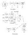
- a Cable Modem Termination System (CMTS) 10communicates with a wide area network 20 , such as the Internet.
- the CMTS 10can transmit signals from the wide area network 20 along a cable network 30 through cable modems 40 to a subscriber's LAN or computer 50 .
- the subscriber's LAN or computer 50 data messagescan be transmitted to the wide area network 20 through the cable modem 40 along the cable network 30 to the CMTS 10 .
- one central end-pointe.g. the head-end
- the number of nodes in communicationvaries in time and can be none, one or two or more at any specific time.
- the link(s) between the head-end and the nodesare combined into one or more channels.
- the signal path from the central end-point to the nodesis referred to as downstream, while the signal path from the nodes to the central end-point is referred to as upstream.
- a single upstream channelcan be used to deliver information from a node to the head-end or from the head-end to a node or a group of nodes. If a single upstream channel is used for communication from the nodes(s) to the central point, then only one end-point can send information on the single upstream channel at any one time.
- Wireless broadband access systemsare also known in the art.
- One problem with many wireless receiver systems used in wireless broadband access systemsis device failure in the components of the RF front end. This is an extremely significant problem for the wireless hub, where there are a number of receivers for each sector. Failure of an individual front end unit could render a whole sector useless.
- the downstream redundancyis based at the Wireless Modem Termination Station (WMTS), where two (2) or three (3) modulators 201 ( a )-( c ) each connect to the same number of transmitters (up converters) 202 ( a )-( c ), where each transmits in a separate downstream channel.
- This systemmay utilize a tuned combiner 203 , to combine the signals from the transmitters 202 ( a )-( c ).
- a power amplifier 204drives the combined signal over the air.
- This configurationcan also include an agile up converter as a backup (not shown). This system enables doubling of the downstream data rate for normal operation.
- the modemIn the case of failure (at a modulator or at a transmitter), the modem will stop receiving the particular frequency, and automatically will switch to a second frequency.
- the advantages of this approachinclude simplicity, doubling the downstream capacity in normal operation, the use of multiple downstream modulation schemes and/or bit rates, and optimization of the maximum capacity according to the receiving capabilities of the modem (distance, interference, multipath, etc.).
- an up converter transmitter manufactured by ADC, model 5100 (and others)has SNMP control.
- an upstream redundant front end schemeis shown. Failure in the upstream can be determined at the WMTS 304 end based on the failure to receive an answer from all the modems on a specific upstream frequency.
- the above conceptenables self-redundancy and self-healing.
- Alternative failure decision criterionincludes combining the RF test point signals from the transmitters, and connecting them to a special modem used for downstream “receive only” testing. This upstream criterion can be used together with the downstream criterion to distinguish between failure in the RF equipment or in the antenna(s) at the basestation.
- Upstream coverageuses a sectorized antenna for reception (up to 24 sectors).
- Each receiving sectorincludes external equipment (antenna, band pass filter, low noise amplifier (LNA), down converter) and a receiver.
- Each sectorcan use multiple upstream frequencies, by splitting the received signal from the down converter, and delivering it to separate receivers at the WMTS ( FIGS. 3 and 4 describe a basic configuration having four frequencies per sector).
- the WMTSincludes eight upstream receiver cards, each of them including four receivers.
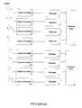
- FIG. 4a front end receiver including full redundancy and antenna diversity is depicted. This configuration is based on the concept of delivering full redundancy without any point of failure.
- the schematic showndepicts a full redundancy configuration for four sectors. The configuration includes doubling the whole chain, from the antenna to the WMTS receiver, for each sector.
- the advantages of the scheme depicted in FIG. 4include:
- the scheme of FIG. 4includes several disadvantages including doubling the antenna weight and wind load required for construction of the tower (e.g. increasing the number of required antennas for 16 sectors) and most importantly the high cost due to the requirement of 32 down converters and antennas for 16 sectors.
- the receiversare part of the WMTS, while the down converters are not.
- the present inventionprovides for a low cost redundancy scheme for the radio frequency front end of a wireless hub that requires a minimum amount of down converters and upstream receivers to implement.
- the redundancyis based upon an implementation utilizing N+1 elements, e.g. downcoverters and upstream receivers, to provide full redundancy for N such elements.
- the backup elementscan be used to support another data stream.
- the low cost redundancy scheme described abovecan optionally be utilized with a LNA redundancy module.
- the present inventionprovides for an efficient low penetration scheme for the radio frequency front end of a wireless hub.
- This embodimentpreferably utilizes as few down converters and upstream receivers as possible, thereby reducing cost
- FIG. 1is an overview of a prior art data over cable system
- FIG. 2is a block diagram of a known redundancy scheme for downstream communication in broadband wireless access network
- FIG. 3is a block diagram of known upstream receiving chain including a down converter and receiver
- FIG. 4is a block diagram of known upstream redundancy scheme for a radio frequency front end
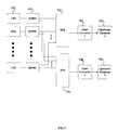
- FIG. 5is a block diagram of a redundancy scheme for a radio frequency front end according to a preferred embodiment of the resent invention
- FIG. 6is a block diagram of a radio frequency front for a low penetration broadband wireless access system according to a preferred embodiment of the present invention.
- FIG. 7is a block diagram of a redundancy scheme for a radio frequency front end for a low penetration wireless broadband access system according to a preferred embodiment of the present invention.
- the front end RF redundancy systemis split to two sections: LNA redundancy and down converter redundancy. It should be noted, however, that the front end RF redundancy can also be performed without using LNA redundancy by simply implementing the down converter redundancy depicted previously. If just the down converter redundancy is utilized, then one of the LNA's 504 and the combiner (2:1) 506 can be removed. While eight receiving chains are illustrated in FIG. 5 , more or less may be implemented as desired. The following discussion focuses on the operation of one chain, but the operation of each chain is identical.
- the LNAis more likely to become damaged due to external conditions, e.g. lightning, and therefore more likely to fail than the down converter. This is because it is located on the front end (except for a narrow band pass filter 500 between the antenna and the LNA).
- the LNA redundancy conceptis based on using two LNAs 503 , 504 for each antenna.
- the signal from the antennais split by a mechanical SPDT switch 501 , which has minimum loss ( ⁇ 0.4 dB) in order not to increase overall noise of the chain and should be highly reliable.
- the output of the two LNAs 503 , 504is connected to a low cost two-way combiner 505 , which delivers signals to the down converter 507 via a splitter 506 .
- the switching between the LNAs 503 , 504is done by switching the SPDT switch 501 , and substantially at the same time controlling the DC voltage supplied to the appropriate LNA. This configuration enables “in operation” maintenance and replacement of the LNAs 503 , 504 .
- a Control Interface Card (or box) 502which is controlled by the wireless hub accomplishes the switching between the two LNAs 503 , 504 .
- This card (or box) 502is connected to the redundant LNA module (including two LNAs).
- the card 502supplies the DC voltage to the two LNAs 503 , 504 , and a control bit to the SPDT switch 501 .
- the interface between the card 502 and the wireless hubis a RS485 interface (or equivalent), for cases where the wireless hub is a far distance from the LNA.
- the wireless hubcontrols the modules for each sector.
- the redundancy schemeis controlled by the wireless hub through the Control Interface Card (CIC). Failure is assumed to occur, when no received signal (or data) is received at the upstream receiver 508 . In this case, the WMTS 520 will automatically switch between the LNAs 503 , 504 . This will be the first repair. If after this activity the received signal (or data) is still missing, the failure will be determined to be in the down converter 507 or in the receiver 508 , and the wireless hub will operate the second stage of redundancy (described below).
- CICControl Interface Card
- the wireless hubIn order to check the two LNAs, the wireless hub periodically switches between them.
- the switching for testingoccurs infrequently without operation of the LNA and will preferably be switched between upstream bursts.
- a down converter 507is located in the receiving chain after the LNAs. It is presently preferred to be a block converter of 6 or 12 MHz (typical 12 MHz). Typically, there will be one down converter for each antenna sector.
- the down converter 507preferably has a high dynamic range to eliminate interference (intermodulation), and has a very stable local oscillator with low phase noise.
- the local oscillatoris preferably locked on a reference oscillator, perhaps derived from a GPS receiver which is part of the wireless hub.
- Down converter and receiver redundancy in FIG. 5is obtained by using a backup chain of one down converter 510 and one upstream receiver 512 as a backup for up to eight (or more) other receiving chains.
- each antennahas a first stage of redundancy for the LNA as is described above.
- a splitter 506splits the output signal of the LNA redundancy module (two LNAs 503 , 504 for each channel) and delivers the output signal of the LNA redundancy module signal to both a directly connected down converter 507 and to a backup down converter 510 .
- a switch 509preferably a SP8T switch, is used to route the output signal of the LNA redundancy module from the selected down converter 507 to the backup down converter 510 and upstream receiver 512 .
- This switch 509is controlled by the wireless hub, through a Control interface Card (CIC) 511 .
- the CIC 511is connected to the wireless hub by an RS485 or similar interface.
- the detection of a failurewill be made by the wireless hub. As has been described above, a failure decision will be made when no receiving signal (or data) occurs. In this case, the wireless hub will automatically switch to the alternate LNA. This will be the first fix. If after this activity the receiving signal is still missing, the failure will be indicated to be in the down converter 507 or in the receiver 508 , and the wireless hub will operate the second stage of redundancy. By controlling the LNAs and switch 509 , the signal will be sent to the backup down converter 510 and backup receiver 512 .
- An example of the utilization of the above described schemecan for example have 16 sectors in which case two switches, 18 down converters, and 18 upstream receivers will be used. For seven sectors, only two upstream receiver cards are needed.
- the backup upstream receiversare located on separate (or mixed) cards from the direct receivers, such that failure of any receiver card is fully backed up by the other cards (in a system including multi-channel cards).
- the above conceptcan be used with the scheme describe above with respect to FIG. 2 to deliver multiple upstream channels per sector, by splitting the signal from each down converter to several upstream receivers.
- the above conceptcan also be implemented with SP4T or SPDT switches for low penetration, when only four or two sectors are used.
- the splitter 506is a passive unit, and is thus unlikely to fail.
- the switch 509also has a very high affective MTBF (Mean Time Between Failure), and even if the switch 509 fails, the signal has a parallel path to the direct down converter.
- Other benefits of the embodimentinclude regular operations when no failure is detected, and the opportunity to use the backup chain (backup down converter and backup upstream receiver) to double the data capacity on any one of the sectors ad hoc.
- the backup chaincan be used on a separate frequency, and dynamically routed to support the busiest of the other sectors.
- the added cost for redundancy for eight sectorsis only an additional 8-way low cost splitter, a down converter, a switch, a CIC (Control Interface Card), and an upstream receiver, which can be used for doubling the capacity of one sector.
- This systemis thus far less expensive than the additional equipment costs described with respect to the system of FIG. 4 .
- the down convertersare integrated with the wireless hub. This has the following advantages: better failure diagnostic and redundancy schemes by allowing greater control and probing of the down converter by the wireless hub; higher dynamic range with a gain controlled by the wireless hub for better matching of the input level range to the receiver, and lower cost.
- a low penetration configurationis based on an architecture similar to the one described with respect to FIG. 5 .
- the low penetration configurationenables a low cost solution with or without redundancy.
- This configurationis based on time sharing of the down converter and receiver for the low penetration period.
- the configurationcan be expanded to the high penetration configuration when it is needed, using the same redundancy elements as described with respect to FIG. 5 .
- a configuration for low penetrationshould be low cost, but should also have the basic elements and allow for simple expansion capability, with no reduction in performance.
- the present schemeinvolves the use of sectorized antennas and the same number of LNAs, but only one down converter 703 (or two 706 for redundancy) and one or two upstream receivers 704 , 707 .
- a switch 702preferably a SP8T switch, is used to route the received signal from the eight LNAs to the down converter 703 .
- the switchingis preferably enabled on a burst by burst basis, or by gathering in time the bursts from some customers in the same sector.
- the wireless hubcontrols when the upstream bursts are assigned a time slot via the same Control Interface Card (CIC) that is used for the high penetration redundancy.
- CICControl Interface Card
- the added cost for a single sectoris an antenna and the LNA(s), but these elements are also used when moving to high penetration, and they deliver better signal to noise ratios without higher cost.
- the added cost of the switch 705can be offset, because it can be used for redundancy later at high penetration periods as was described before.
- the cost savingsincludes the cost of the seven down converters which are needed for high penetration, eight sectors and an upstream receiver card.
- an advantage of the schemes described with reference to FIGS. 6 and 7is that it is easy to install many additional demodulation channels, thereby increasing the capacity in a relatively short time.
- FIGS. 5 through 7operate according to the DOCSIS specifications which are incorporated herein by reference in their entirety as if fully set forth herein.
Landscapes
- Engineering & Computer Science (AREA)
- Computer Networks & Wireless Communication (AREA)
- Signal Processing (AREA)
- Mobile Radio Communication Systems (AREA)
Abstract
Description
- 1. It enables implementation of antenna diversity (dual antennas per sector);
- 2. Full upstream redundancy, allowing the option of doubling upstream capacity (for high penetration);
- 3. No single point of failure, and ease of redundancy control (development of switching mechanism is not required).
Claims (22)
Priority Applications (1)
| Application Number | Priority Date | Filing Date | Title |
|---|---|---|---|
| US09/771,224US6941119B2 (en) | 2000-01-26 | 2001-01-26 | Redundancy scheme for the radio frequency front end of a broadband wireless hub |
Applications Claiming Priority (2)
| Application Number | Priority Date | Filing Date | Title |
|---|---|---|---|
| US17815400P | 2000-01-26 | 2000-01-26 | |
| US09/771,224US6941119B2 (en) | 2000-01-26 | 2001-01-26 | Redundancy scheme for the radio frequency front end of a broadband wireless hub |
Publications (2)
| Publication Number | Publication Date |
|---|---|
| US20010051512A1 US20010051512A1 (en) | 2001-12-13 |
| US6941119B2true US6941119B2 (en) | 2005-09-06 |
Family
ID=26874029
Family Applications (1)
| Application Number | Title | Priority Date | Filing Date |
|---|---|---|---|
| US09/771,224Expired - LifetimeUS6941119B2 (en) | 2000-01-26 | 2001-01-26 | Redundancy scheme for the radio frequency front end of a broadband wireless hub |
Country Status (1)
| Country | Link |
|---|---|
| US (1) | US6941119B2 (en) |
Cited By (5)
| Publication number | Priority date | Publication date | Assignee | Title |
|---|---|---|---|---|
| US20030185163A1 (en)* | 2002-03-27 | 2003-10-02 | Bertonis James G. | System and method for wireless cable data transmission |
| US20100210236A1 (en)* | 2009-01-06 | 2010-08-19 | Khemakhem M Hamed Anis | Rf circuit module and panel |
| US20100255776A1 (en)* | 2006-08-29 | 2010-10-07 | Hudson Erwin C | Redundant communication path for satellite communication data |
| US20110007686A1 (en)* | 2007-04-13 | 2011-01-13 | Space Systems/Loral, Inc. | Multi-beam satellite network to maximize bandwidth utilization |
| US9236934B1 (en) | 2009-10-16 | 2016-01-12 | Viasat, Inc. | Satellite system architecture for coverage areas of disparate demand |
Families Citing this family (4)
| Publication number | Priority date | Publication date | Assignee | Title |
|---|---|---|---|---|
| US7386061B1 (en)* | 2000-10-24 | 2008-06-10 | Agere Systems Inc. | Apparatus and method for multi-channel receiver front end |
| CN1194574C (en)* | 2001-09-11 | 2005-03-23 | 三星电子株式会社 | Base station system supporting multi-sector/multi-frequency allocation for seamless call service |
| US7212788B2 (en)* | 2002-08-13 | 2007-05-01 | Atheros Communications, Inc. | Method and apparatus for signal power loss reduction in RF communication systems |
| US8532588B1 (en) | 2002-08-13 | 2013-09-10 | The Connectivity Patent Trust | Apparatus for signal power loss reduction in RF communication systems |
Citations (62)
| Publication number | Priority date | Publication date | Assignee | Title |
|---|---|---|---|---|
| US4010465A (en) | 1975-04-04 | 1977-03-01 | International Telephone And Telegraph Corporation | Channel encoding for distance measurement equipment |
| US4099121A (en) | 1976-06-11 | 1978-07-04 | Communications Satellite Corporation | Spatial diversity satellite communications system with error control |
| EP0021544A1 (en) | 1979-06-28 | 1981-01-07 | Staat der Nederlanden (Staatsbedrijf der Posterijen, Telegrafie en Telefonie) | System for the remote testing of a modem for a speed of transmission different from the speed of reception |
| EP0025767A1 (en) | 1979-09-18 | 1981-03-25 | Lignes Telegraphiques Et Telephoniques L.T.T. | Method and apparatus for automatically testing a digital data transmission system |
| US4385384A (en) | 1977-06-06 | 1983-05-24 | Racal Data Communications Inc. | Modem diagnostic and control system |
| US5052024A (en) | 1990-05-23 | 1991-09-24 | Motorola, Inc. | Offset frequency multipoint modem and communications network |
| US5272700A (en) | 1989-02-28 | 1993-12-21 | First Pacific Networks, Inc. | Spectrally efficient broadband transmission system |
| US5311550A (en) | 1988-10-21 | 1994-05-10 | Thomson-Csf | Transmitter, transmission method and receiver |
| US5377035A (en) | 1993-09-28 | 1994-12-27 | Hughes Aircraft Company | Wavelength division multiplexed fiber optic link for RF polarization diversity receiver |
| US5408349A (en) | 1991-07-05 | 1995-04-18 | Hitachi, Ltd. | Optical frequency division multiplexing transmission system |
| US5471645A (en) | 1992-09-25 | 1995-11-28 | Motorola | Method of allocating channels in multi-rate channel environment |
| US5481542A (en) | 1993-11-10 | 1996-01-02 | Scientific-Atlanta, Inc. | Interactive information services control system |
| US5481561A (en) | 1991-05-29 | 1996-01-02 | Comsat Corporation | Fully meshed CDMA network for personal communications terminals |
| US5487099A (en) | 1993-01-29 | 1996-01-23 | Mitsubishi Denki Kabushiki Kaisha | Portable telephone having an additional device for making external connections |
| US5510859A (en) | 1993-07-27 | 1996-04-23 | Information Resources, Inc. | Tuned signal detector for use with a radio frequency receiver |
| US5557612A (en) | 1995-01-20 | 1996-09-17 | Amati Communications Corporation | Method and apparatus for establishing communication in a multi-tone data transmission system |
| US5590409A (en) | 1994-05-12 | 1996-12-31 | Ntt Mobile Communications Network Inc. | Transmission power control method and a transmission power control apparatus |
| US5596604A (en) | 1993-08-17 | 1997-01-21 | Amati Communications Corporation | Multicarrier modulation transmission system with variable delay |
| US5606664A (en) | 1990-05-21 | 1997-02-25 | Bay Networks, Inc. | Apparatus and method for automatically determining the topology of a local area network |
| US5625874A (en) | 1993-12-24 | 1997-04-29 | Nec Corporation | Terminal station which does not cause an interruption of communication on changing of a communication system |
| US5634206A (en) | 1995-05-25 | 1997-05-27 | Motorola, Inc. | Method and apparatus for estimating a signal fading characteristic |
| US5666646A (en) | 1995-04-10 | 1997-09-09 | Comtech | Radio frequency (RF) converter system with distributed protection switching and method therefor |
| US5724385A (en) | 1994-09-30 | 1998-03-03 | Qualcomm Incorporated | Serial linked interconnect for summation of multiple waveforms on a common channel |
| US5734589A (en) | 1995-01-31 | 1998-03-31 | Bell Atlantic Network Services, Inc. | Digital entertainment terminal with channel mapping |
| CA2187141A1 (en) | 1996-10-04 | 1998-04-04 | Richard Vallee | Modem with remote monitoring capability |
| US5740525A (en) | 1996-05-10 | 1998-04-14 | Motorola, Inc. | Method and apparatus for temperature compensation of a reference oscillator in a communication device |
| US5752161A (en) | 1993-09-24 | 1998-05-12 | Nokia Telecommunications Oy | Method and apparatus for replacing a failed channel unit of a sectored base station, in a cellular radio system, with an additional channel unit |
| US5796783A (en) | 1995-10-31 | 1998-08-18 | Andre Alain Tabourian | Digital transmission system |
| US5809090A (en) | 1996-03-04 | 1998-09-15 | Glenayre Electronics, Inc. | Digital diversity receiver system |
| US5809427A (en) | 1996-03-28 | 1998-09-15 | Motorola Inc. | Apparatus and method for channel acquisition in a communication system |
| US5809406A (en) | 1994-12-15 | 1998-09-15 | Fujitsu Limited | Receiving apparatus and method for switching between active and standby receivers |
| US5818825A (en) | 1995-11-29 | 1998-10-06 | Motorola, Inc. | Method and apparatus for assigning communications channels in a cable telephony system |
| US5831690A (en) | 1996-12-06 | 1998-11-03 | Rca Thomson Licensing Corporation | Apparatus for formatting a packetized digital datastream suitable for conveying television information |
| US5862451A (en) | 1996-01-22 | 1999-01-19 | Motorola, Inc. | Channel quality management in a cable telephony system |
| US5867528A (en) | 1996-01-16 | 1999-02-02 | Alcatel Alsthom Compagnie Generale D'electricite | Method and modem for adaptive allocation of the pilot carrier in a multi-carrier system |
| US5896414A (en) | 1996-09-17 | 1999-04-20 | Sarnoff Corporation | Method and apparatus for providing control channel communications for an information distribution system |
| US5903558A (en) | 1996-06-28 | 1999-05-11 | Motorola, Inc. | Method and system for maintaining a guaranteed quality of service in data transfers within a communications system |
| US5909384A (en) | 1996-10-04 | 1999-06-01 | Conexant Systems, Inc. | System for dynamically adapting the length of a filter |
| US5937005A (en) | 1995-08-22 | 1999-08-10 | Fujitsu Limited | Error rate measurement apparatus for a mobile radio communications system |
| US5940743A (en) | 1997-06-05 | 1999-08-17 | Nokia Mobile Phones Limited | Power control of mobile station transmissions during handoff in a cellular system |
| US5963870A (en) | 1997-03-26 | 1999-10-05 | Nortel Networks Corporation | Process for switching between IS-95 forward power control and fast forward power control |
| US5963843A (en) | 1996-12-09 | 1999-10-05 | Adc Telecommunications, Inc. | Amplifier switch controller and system |
| US5974106A (en) | 1995-09-01 | 1999-10-26 | Motorola, Inc. | Method and apparatus for multirate data communications |
| US5978855A (en) | 1994-05-27 | 1999-11-02 | Bell Atlantic Network Services, Inc. | Downloading applications software through a broadcast channel |
| US5991286A (en) | 1997-02-20 | 1999-11-23 | Telefonaktiebolaget L M Ericsson (Publ) | Support of multiple modulation levels for a cellular packet control channel |
| US6009310A (en) | 1996-08-14 | 1999-12-28 | Nec Corporation | Radio selective calling receiver using diversity reception |
| US6018644A (en)* | 1997-01-28 | 2000-01-25 | Northrop Grumman Corporation | Low-loss, fault-tolerant antenna interface unit |
| US6035008A (en) | 1996-10-05 | 2000-03-07 | Samsung Electronics Co., Ltd. | Automatic gain control in direct sequence spread spectrum communication system |
| US6052408A (en) | 1995-09-06 | 2000-04-18 | Aironet Wireless Communications, Inc. | Cellular communication system with dynamically modified data transmission parameters |
| US6072839A (en) | 1997-07-24 | 2000-06-06 | Lucent Technologies, Inc. | DVB frame synchronization |
| US6075787A (en) | 1997-05-08 | 2000-06-13 | Lucent Technologies Inc. | Method and apparatus for messaging, signaling, and establishing a data link utilizing multiple modes over a multiple access broadband communications network |
| US6112232A (en) | 1998-01-27 | 2000-08-29 | Phasecom Ltd. | Data communication device for CATV networks |
| US6111887A (en) | 1997-10-08 | 2000-08-29 | Zenith Electronics Corporation | Method and apparatus for power tuning a terminal of a bi-directional communications system |
| US6128588A (en) | 1997-10-01 | 2000-10-03 | Sony Corporation | Integrated wafer fab time standard (machine tact) database |
| US6140911A (en) | 1997-05-29 | 2000-10-31 | 3Com Corporation | Power transfer apparatus for concurrently transmitting data and power over data wires |
| US6141356A (en) | 1997-11-10 | 2000-10-31 | Ameritech Corporation | System and method for distributing voice and data information over wireless and wireline networks |
| US6157311A (en) | 1999-01-07 | 2000-12-05 | Berkovich; Yossi | Portable electro-magnetic radiation sensor warning device |
| US6160447A (en) | 1999-02-10 | 2000-12-12 | Adc Solitra, Inc. | Amplifier having redundancies |
| US6172970B1 (en) | 1997-05-05 | 2001-01-09 | The Hong Kong University Of Science And Technology | Low-complexity antenna diversity receiver |
| US6185227B1 (en) | 1999-07-22 | 2001-02-06 | Nokia Networks Oy | Method and packet radio system for transmitting modulation and signalling information |
| US6195697B1 (en) | 1999-06-02 | 2001-02-27 | Ac Properties B.V. | System, method and article of manufacture for providing a customer interface in a hybrid network |
| US6745004B2 (en)* | 2001-05-22 | 2004-06-01 | Northrop Grumman Corporation | Satellite frequency generation incorporating secondary power supply |
- 2001
- 2001-01-26USUS09/771,224patent/US6941119B2/ennot_activeExpired - Lifetime
Patent Citations (62)
| Publication number | Priority date | Publication date | Assignee | Title |
|---|---|---|---|---|
| US4010465A (en) | 1975-04-04 | 1977-03-01 | International Telephone And Telegraph Corporation | Channel encoding for distance measurement equipment |
| US4099121A (en) | 1976-06-11 | 1978-07-04 | Communications Satellite Corporation | Spatial diversity satellite communications system with error control |
| US4385384A (en) | 1977-06-06 | 1983-05-24 | Racal Data Communications Inc. | Modem diagnostic and control system |
| EP0021544A1 (en) | 1979-06-28 | 1981-01-07 | Staat der Nederlanden (Staatsbedrijf der Posterijen, Telegrafie en Telefonie) | System for the remote testing of a modem for a speed of transmission different from the speed of reception |
| EP0025767A1 (en) | 1979-09-18 | 1981-03-25 | Lignes Telegraphiques Et Telephoniques L.T.T. | Method and apparatus for automatically testing a digital data transmission system |
| US5311550A (en) | 1988-10-21 | 1994-05-10 | Thomson-Csf | Transmitter, transmission method and receiver |
| US5272700A (en) | 1989-02-28 | 1993-12-21 | First Pacific Networks, Inc. | Spectrally efficient broadband transmission system |
| US5606664A (en) | 1990-05-21 | 1997-02-25 | Bay Networks, Inc. | Apparatus and method for automatically determining the topology of a local area network |
| US5052024A (en) | 1990-05-23 | 1991-09-24 | Motorola, Inc. | Offset frequency multipoint modem and communications network |
| US5481561A (en) | 1991-05-29 | 1996-01-02 | Comsat Corporation | Fully meshed CDMA network for personal communications terminals |
| US5408349A (en) | 1991-07-05 | 1995-04-18 | Hitachi, Ltd. | Optical frequency division multiplexing transmission system |
| US5471645A (en) | 1992-09-25 | 1995-11-28 | Motorola | Method of allocating channels in multi-rate channel environment |
| US5487099A (en) | 1993-01-29 | 1996-01-23 | Mitsubishi Denki Kabushiki Kaisha | Portable telephone having an additional device for making external connections |
| US5510859A (en) | 1993-07-27 | 1996-04-23 | Information Resources, Inc. | Tuned signal detector for use with a radio frequency receiver |
| US5596604A (en) | 1993-08-17 | 1997-01-21 | Amati Communications Corporation | Multicarrier modulation transmission system with variable delay |
| US5752161A (en) | 1993-09-24 | 1998-05-12 | Nokia Telecommunications Oy | Method and apparatus for replacing a failed channel unit of a sectored base station, in a cellular radio system, with an additional channel unit |
| US5377035A (en) | 1993-09-28 | 1994-12-27 | Hughes Aircraft Company | Wavelength division multiplexed fiber optic link for RF polarization diversity receiver |
| US5481542A (en) | 1993-11-10 | 1996-01-02 | Scientific-Atlanta, Inc. | Interactive information services control system |
| US5625874A (en) | 1993-12-24 | 1997-04-29 | Nec Corporation | Terminal station which does not cause an interruption of communication on changing of a communication system |
| US5590409A (en) | 1994-05-12 | 1996-12-31 | Ntt Mobile Communications Network Inc. | Transmission power control method and a transmission power control apparatus |
| US5978855A (en) | 1994-05-27 | 1999-11-02 | Bell Atlantic Network Services, Inc. | Downloading applications software through a broadcast channel |
| US5724385A (en) | 1994-09-30 | 1998-03-03 | Qualcomm Incorporated | Serial linked interconnect for summation of multiple waveforms on a common channel |
| US5809406A (en) | 1994-12-15 | 1998-09-15 | Fujitsu Limited | Receiving apparatus and method for switching between active and standby receivers |
| US5557612A (en) | 1995-01-20 | 1996-09-17 | Amati Communications Corporation | Method and apparatus for establishing communication in a multi-tone data transmission system |
| US5734589A (en) | 1995-01-31 | 1998-03-31 | Bell Atlantic Network Services, Inc. | Digital entertainment terminal with channel mapping |
| US5666646A (en) | 1995-04-10 | 1997-09-09 | Comtech | Radio frequency (RF) converter system with distributed protection switching and method therefor |
| US5634206A (en) | 1995-05-25 | 1997-05-27 | Motorola, Inc. | Method and apparatus for estimating a signal fading characteristic |
| US5937005A (en) | 1995-08-22 | 1999-08-10 | Fujitsu Limited | Error rate measurement apparatus for a mobile radio communications system |
| US5974106A (en) | 1995-09-01 | 1999-10-26 | Motorola, Inc. | Method and apparatus for multirate data communications |
| US6052408A (en) | 1995-09-06 | 2000-04-18 | Aironet Wireless Communications, Inc. | Cellular communication system with dynamically modified data transmission parameters |
| US5796783A (en) | 1995-10-31 | 1998-08-18 | Andre Alain Tabourian | Digital transmission system |
| US5818825A (en) | 1995-11-29 | 1998-10-06 | Motorola, Inc. | Method and apparatus for assigning communications channels in a cable telephony system |
| US5867528A (en) | 1996-01-16 | 1999-02-02 | Alcatel Alsthom Compagnie Generale D'electricite | Method and modem for adaptive allocation of the pilot carrier in a multi-carrier system |
| US5862451A (en) | 1996-01-22 | 1999-01-19 | Motorola, Inc. | Channel quality management in a cable telephony system |
| US5809090A (en) | 1996-03-04 | 1998-09-15 | Glenayre Electronics, Inc. | Digital diversity receiver system |
| US5809427A (en) | 1996-03-28 | 1998-09-15 | Motorola Inc. | Apparatus and method for channel acquisition in a communication system |
| US5740525A (en) | 1996-05-10 | 1998-04-14 | Motorola, Inc. | Method and apparatus for temperature compensation of a reference oscillator in a communication device |
| US5903558A (en) | 1996-06-28 | 1999-05-11 | Motorola, Inc. | Method and system for maintaining a guaranteed quality of service in data transfers within a communications system |
| US6009310A (en) | 1996-08-14 | 1999-12-28 | Nec Corporation | Radio selective calling receiver using diversity reception |
| US5896414A (en) | 1996-09-17 | 1999-04-20 | Sarnoff Corporation | Method and apparatus for providing control channel communications for an information distribution system |
| CA2187141A1 (en) | 1996-10-04 | 1998-04-04 | Richard Vallee | Modem with remote monitoring capability |
| US5909384A (en) | 1996-10-04 | 1999-06-01 | Conexant Systems, Inc. | System for dynamically adapting the length of a filter |
| US6035008A (en) | 1996-10-05 | 2000-03-07 | Samsung Electronics Co., Ltd. | Automatic gain control in direct sequence spread spectrum communication system |
| US5831690A (en) | 1996-12-06 | 1998-11-03 | Rca Thomson Licensing Corporation | Apparatus for formatting a packetized digital datastream suitable for conveying television information |
| US5963843A (en) | 1996-12-09 | 1999-10-05 | Adc Telecommunications, Inc. | Amplifier switch controller and system |
| US6018644A (en)* | 1997-01-28 | 2000-01-25 | Northrop Grumman Corporation | Low-loss, fault-tolerant antenna interface unit |
| US5991286A (en) | 1997-02-20 | 1999-11-23 | Telefonaktiebolaget L M Ericsson (Publ) | Support of multiple modulation levels for a cellular packet control channel |
| US5963870A (en) | 1997-03-26 | 1999-10-05 | Nortel Networks Corporation | Process for switching between IS-95 forward power control and fast forward power control |
| US6172970B1 (en) | 1997-05-05 | 2001-01-09 | The Hong Kong University Of Science And Technology | Low-complexity antenna diversity receiver |
| US6075787A (en) | 1997-05-08 | 2000-06-13 | Lucent Technologies Inc. | Method and apparatus for messaging, signaling, and establishing a data link utilizing multiple modes over a multiple access broadband communications network |
| US6140911A (en) | 1997-05-29 | 2000-10-31 | 3Com Corporation | Power transfer apparatus for concurrently transmitting data and power over data wires |
| US5940743A (en) | 1997-06-05 | 1999-08-17 | Nokia Mobile Phones Limited | Power control of mobile station transmissions during handoff in a cellular system |
| US6072839A (en) | 1997-07-24 | 2000-06-06 | Lucent Technologies, Inc. | DVB frame synchronization |
| US6128588A (en) | 1997-10-01 | 2000-10-03 | Sony Corporation | Integrated wafer fab time standard (machine tact) database |
| US6111887A (en) | 1997-10-08 | 2000-08-29 | Zenith Electronics Corporation | Method and apparatus for power tuning a terminal of a bi-directional communications system |
| US6141356A (en) | 1997-11-10 | 2000-10-31 | Ameritech Corporation | System and method for distributing voice and data information over wireless and wireline networks |
| US6112232A (en) | 1998-01-27 | 2000-08-29 | Phasecom Ltd. | Data communication device for CATV networks |
| US6157311A (en) | 1999-01-07 | 2000-12-05 | Berkovich; Yossi | Portable electro-magnetic radiation sensor warning device |
| US6160447A (en) | 1999-02-10 | 2000-12-12 | Adc Solitra, Inc. | Amplifier having redundancies |
| US6195697B1 (en) | 1999-06-02 | 2001-02-27 | Ac Properties B.V. | System, method and article of manufacture for providing a customer interface in a hybrid network |
| US6185227B1 (en) | 1999-07-22 | 2001-02-06 | Nokia Networks Oy | Method and packet radio system for transmitting modulation and signalling information |
| US6745004B2 (en)* | 2001-05-22 | 2004-06-01 | Northrop Grumman Corporation | Satellite frequency generation incorporating secondary power supply |
Non-Patent Citations (13)
| Title |
|---|
| Data Over Cable Interface Specifications, Cable Modem Termination System-Network Side Interface Specification, SP-CMTS-NSII01-960702 (Jul. 2, 1996) pp. i-13. |
| Data-Over-Cable Service Interface Specifications, Baseline Privacy Interface Specification, SP-BPI-102-990319 (Mar. 19, 1999) pp. i-88. |
| Data-Over-Cable Service Interface Specifications, Baseline Privacy Interface Specification, SP-BPI-102-990731 (Jul. 31, 1999) pp. i-160. |
| Data-Over-Cable Service Interface Specifications, Cable Modem to Customer Premise Equipment Interface Specification. SP-CMC1-102-980317 (Mar. 17, 1998) pp. i-40. |
| Data-Over-Cable Service Interface Specifications, Operations Support System Interface Specification Radio Frequency Interface, SP-OSSI-RFI-103-990113 (Jan. 13, 1999) pp. i-29. |
| Data-Over-Cable Service Interface Specifications, Operations Support System Interface Specification SP-OSSI-102-990113 (Jan. 13, 1999) pp. i-14. |
| Data-Over-Cable Service Interface Specifications, Operations Support System Interface Specification SP-OSSIv1.1-103-001220 (Dec. 20, 2000) p. ii. |
| Data-Over-Cable Service Interface Specifications, Operations Support System Interface Specification SP-OSSIv1.1-D01-991115 (Nov. 15, 1999) pp. i-81. |
| Data-Over-Cable Service Interface Specifications, Radio Frequency Interface Specification, SP-RFI-I04-980724 (Jul. 24, 1998) pp. i-196. |
| Data-Over-Cable Service Interface Specifications, Radio Frequency Interface Specification, SP-RFIv1.1-I03-991105 (Nov. 5, 1999) pp. i-366. |
| Golestani, S. (1995) "Network Delay Analysis on a Class of Fair Queueing Algorithms", IEEE Journal of Selected Areas in Communication 13(6):1057-1070. |
| Stiliadis, D. et al., (1998) "Efficient Fair Queuing Algorithms for Packet-Switched Networks", IEEE/ACM Transactions of Networking 6(2):175-185. |
| Stiliadis, D. et al., (1998) "Rate-Proportional Servers: A Design Methodology for Fair Queueing Algorithms", IEEE/ACM Transactions of Networking 6(2):164-174. |
Cited By (10)
| Publication number | Priority date | Publication date | Assignee | Title |
|---|---|---|---|---|
| US20030185163A1 (en)* | 2002-03-27 | 2003-10-02 | Bertonis James G. | System and method for wireless cable data transmission |
| US20100255776A1 (en)* | 2006-08-29 | 2010-10-07 | Hudson Erwin C | Redundant communication path for satellite communication data |
| US8634768B2 (en) | 2006-08-29 | 2014-01-21 | Viasat, Inc. | Redundant communication path for satellite communication data |
| US20110007686A1 (en)* | 2007-04-13 | 2011-01-13 | Space Systems/Loral, Inc. | Multi-beam satellite network to maximize bandwidth utilization |
| US20100210236A1 (en)* | 2009-01-06 | 2010-08-19 | Khemakhem M Hamed Anis | Rf circuit module and panel |
| US8731603B2 (en)* | 2009-01-06 | 2014-05-20 | Adc Telecommunications, Inc. | RF circuit module and panel |
| US9236934B1 (en) | 2009-10-16 | 2016-01-12 | Viasat, Inc. | Satellite system architecture for coverage areas of disparate demand |
| US9654203B2 (en) | 2009-10-16 | 2017-05-16 | Viasat, Inc. | Satellite system architecture for coverage areas of disparate demand |
| US10305579B2 (en) | 2009-10-16 | 2019-05-28 | Viasat, Inc. | Satellite system architecture for coverage areas of disparate demand |
| US10727933B2 (en) | 2009-10-16 | 2020-07-28 | Viasat, Inc. | Satellite system architecture for coverage areas of disparate demand |
Also Published As
| Publication number | Publication date |
|---|---|
| US20010051512A1 (en) | 2001-12-13 |
Similar Documents
| Publication | Publication Date | Title |
|---|---|---|
| US11381312B2 (en) | Redundancy in a public safety distributed antenna system | |
| US9859982B2 (en) | Distributed antenna system | |
| EP2352358B1 (en) | Communication system and method | |
| US9826410B2 (en) | Distributed antenna system for wireless network systems | |
| US8417116B2 (en) | RoF system providing HD wireless communication service and signal control method for the same | |
| US7450853B2 (en) | Signal transmission apparatus and method for optical base station | |
| US5802173A (en) | Radiotelephony system | |
| EP2294722B1 (en) | System and method for configurable time-division duplex interface | |
| US20080287163A1 (en) | Method and apparatus for converting between a multi-sector, omni-base station configuration and a multi-sector base station configuration | |
| CN211830769U (en) | 5G frequency conversion light distribution system | |
| US6738597B1 (en) | Repeating installation using telephone line | |
| US20100296458A1 (en) | Method of inserting cdma beacon pilots in output of distributed remote antenna nodes | |
| CN101304279B (en) | Radio frequency extension apparatus and base station system | |
| EP3343820A1 (en) | Distributing wireless communication signals over metropolitan telecommunication networks | |
| US6941119B2 (en) | Redundancy scheme for the radio frequency front end of a broadband wireless hub | |
| JP2001168778A (en) | Wireless communication base station | |
| US6438359B1 (en) | Dual transmitter arrangement with back-up switching | |
| US6917803B2 (en) | Wireless communications equipment | |
| JP6761428B2 (en) | Satellite signal relay system | |
| CN201260163Y (en) | Radio frequency extension apparatus and base station system | |
| WO2001056217A2 (en) | Redundancy scheme for the radio frequency front end of a broadband wireless hub | |
| KR100434339B1 (en) | power amplification sharing device of the base-station | |
| JP2000332702A (en) | Digital broadcast wave quality monitoring system |
Legal Events
| Date | Code | Title | Description |
|---|---|---|---|
| AS | Assignment | Owner name:VYYO LTD., ISRAEL Free format text:ASSIGNMENT OF ASSIGNORS INTEREST;ASSIGNORS:WILSON, ERIC K.;HENDLER, HILLEL;REEL/FRAME:011790/0768;SIGNING DATES FROM 20010424 TO 20010503 | |
| STCF | Information on status: patent grant | Free format text:PATENTED CASE | |
| AS | Assignment | Owner name:VYYO INC., GEORGIA Free format text:ASSIGNMENT OF ASSIGNORS INTEREST;ASSIGNOR:VYYO LTD.;REEL/FRAME:019966/0264 Effective date:20070917 | |
| AS | Assignment | Owner name:GOLDMAN SACHS INVESTMENT PARTNERS MASTER FUND, L.P Free format text:SECURITY AGREEMENT;ASSIGNOR:VYYO, INC.;REEL/FRAME:021182/0372 Effective date:20080613 | |
| AS | Assignment | Owner name:GILO VENTURES IL, L.P., CALIFORNIA Free format text:SECURITY AGREEMENT;ASSIGNOR:VYYO INC.;REEL/FRAME:021648/0536 Effective date:20080930 Owner name:GILO VENTURES IL, L.P.,CALIFORNIA Free format text:SECURITY AGREEMENT;ASSIGNOR:VYYO INC.;REEL/FRAME:021648/0536 Effective date:20080930 | |
| FEPP | Fee payment procedure | Free format text:PAYER NUMBER DE-ASSIGNED (ORIGINAL EVENT CODE: RMPN); ENTITY STATUS OF PATENT OWNER: LARGE ENTITY Free format text:PAYOR NUMBER ASSIGNED (ORIGINAL EVENT CODE: ASPN); ENTITY STATUS OF PATENT OWNER: LARGE ENTITY | |
| AS | Assignment | Owner name:GILO VENTURES II, L.P., CALIFORNIA Free format text:CORRECTIVE ASSIGNMENT TO CORRECT THE ASSIGNEE'S CORRECT NAME IS;ASSIGNOR:VYYO INC.;REEL/FRAME:021962/0088 Effective date:20080930 | |
| REMI | Maintenance fee reminder mailed | ||
| FPAY | Fee payment | Year of fee payment:4 | |
| SULP | Surcharge for late payment | ||
| AS | Assignment | Owner name:XTEND NETWORKS, INC., GEORGIA Free format text:RELEASE BY SECURED PARTY;ASSIGNORS:GOLDMAN SACHS INVESTMENT PARTNERS AGGREGATING FUND HOLDINGS, L.P.;SYNTEK CAPITAL GMBH;GILO VENTURES II, L.P.;REEL/FRAME:026379/0319 Effective date:20110101 Owner name:XTEND NETWORKS LTD., ISRAEL Free format text:RELEASE BY SECURED PARTY;ASSIGNORS:GOLDMAN SACHS INVESTMENT PARTNERS AGGREGATING FUND HOLDINGS, L.P.;SYNTEK CAPITAL GMBH;GILO VENTURES II, L.P.;REEL/FRAME:026379/0319 Effective date:20110101 Owner name:JAVELIN INNOVATIONS, INC., CALIFORNIA Free format text:RELEASE BY SECURED PARTY;ASSIGNORS:GOLDMAN SACHS INVESTMENT PARTNERS AGGREGATING FUND HOLDINGS, L.P.;SYNTEK CAPITAL GMBH;GILO VENTURES II, L.P.;REEL/FRAME:026379/0319 Effective date:20110101 Owner name:VYYO LTD., ISRAEL Free format text:RELEASE BY SECURED PARTY;ASSIGNORS:GOLDMAN SACHS INVESTMENT PARTNERS AGGREGATING FUND HOLDINGS, L.P.;SYNTEK CAPITAL GMBH;GILO VENTURES II, L.P.;REEL/FRAME:026379/0319 Effective date:20110101 | |
| FEPP | Fee payment procedure | Free format text:PAYER NUMBER DE-ASSIGNED (ORIGINAL EVENT CODE: RMPN); ENTITY STATUS OF PATENT OWNER: LARGE ENTITY Free format text:PAYOR NUMBER ASSIGNED (ORIGINAL EVENT CODE: ASPN); ENTITY STATUS OF PATENT OWNER: LARGE ENTITY | |
| AS | Assignment | Owner name:XTEND NETWORKS LTD., ISRAEL Free format text:CORRECTIVE ASSIGNMENT TO CORRECT THE RELEASE BY SECURED PARTY TO INCLUDE ITEMIZED LISTING OF PROPERTIES NOT FOUND IN PREVIOUSLY RECORDED ON REEL 026379 FRAME 0319. ASSIGNOR(S) HEREBY CONFIRMS THE ITEMIZED LISTING OF PROPERTIES NOT FOUND IN REEL/FRAME 026379/0319 IS NOW COMPLETE;ASSIGNORS:GOLDMAN SACHS INVESTMENT PARTNERS AGGREGATING FUND HOLDINGS, L.P.;SYNTEK CAPITAL GMBH;GILO VENTURES II. L.P.;REEL/FRAME:028049/0491 Effective date:20110101 Owner name:XTEND NETWORKS, INC., GEORGIA Free format text:CORRECTIVE ASSIGNMENT TO CORRECT THE RELEASE BY SECURED PARTY TO INCLUDE ITEMIZED LISTING OF PROPERTIES NOT FOUND IN PREVIOUSLY RECORDED ON REEL 026379 FRAME 0319. ASSIGNOR(S) HEREBY CONFIRMS THE ITEMIZED LISTING OF PROPERTIES NOT FOUND IN REEL/FRAME 026379/0319 IS NOW COMPLETE;ASSIGNORS:GOLDMAN SACHS INVESTMENT PARTNERS AGGREGATING FUND HOLDINGS, L.P.;SYNTEK CAPITAL GMBH;GILO VENTURES II. L.P.;REEL/FRAME:028049/0491 Effective date:20110101 Owner name:VYYO LTD., ISRAEL Free format text:CORRECTIVE ASSIGNMENT TO CORRECT THE RELEASE BY SECURED PARTY TO INCLUDE ITEMIZED LISTING OF PROPERTIES NOT FOUND IN PREVIOUSLY RECORDED ON REEL 026379 FRAME 0319. ASSIGNOR(S) HEREBY CONFIRMS THE ITEMIZED LISTING OF PROPERTIES NOT FOUND IN REEL/FRAME 026379/0319 IS NOW COMPLETE;ASSIGNORS:GOLDMAN SACHS INVESTMENT PARTNERS AGGREGATING FUND HOLDINGS, L.P.;SYNTEK CAPITAL GMBH;GILO VENTURES II. L.P.;REEL/FRAME:028049/0491 Effective date:20110101 Owner name:JAVELIN INNOVATIONS, INC., CALIFORNIA Free format text:CORRECTIVE ASSIGNMENT TO CORRECT THE RELEASE BY SECURED PARTY TO INCLUDE ITEMIZED LISTING OF PROPERTIES NOT FOUND IN PREVIOUSLY RECORDED ON REEL 026379 FRAME 0319. ASSIGNOR(S) HEREBY CONFIRMS THE ITEMIZED LISTING OF PROPERTIES NOT FOUND IN REEL/FRAME 026379/0319 IS NOW COMPLETE;ASSIGNORS:GOLDMAN SACHS INVESTMENT PARTNERS AGGREGATING FUND HOLDINGS, L.P.;SYNTEK CAPITAL GMBH;GILO VENTURES II. L.P.;REEL/FRAME:028049/0491 Effective date:20110101 | |
| AS | Assignment | Owner name:JAVELIN INNOVATIONS INC., CALIFORNIA Free format text:RELEASE BY SECURED PARTY;ASSIGNOR:GOLDMAN SACHS INVESTMENT PARTNERS AGGREGATING FUND HOLDING, L.P.;REEL/FRAME:028791/0147 Effective date:20120504 | |
| AS | Assignment | Owner name:JAVELIN INNOVATIONS INC., GEORGIA Free format text:CHANGE OF NAME;ASSIGNOR:VYYO INC.;REEL/FRAME:028923/0366 Effective date:20090223 Owner name:IMAGO RESEARCH LIMITED LIABILITY COMPANY, DELAWARE Free format text:ASSIGNMENT OF ASSIGNORS INTEREST;ASSIGNOR:NEW ARCADIAN NETWORKS, INC.;REEL/FRAME:028921/0857 Effective date:20120427 Owner name:NEW ARCADIAN NETWORKS, INC., NEW YORK Free format text:ASSIGNMENT OF ASSIGNORS INTEREST;ASSIGNOR:JAVELIN INNOVATIONS INC.;REEL/FRAME:028923/0370 Effective date:20120425 Owner name:VYYO, INC., GEORGIA Free format text:NUNC PRO TUNC ASSIGNMENT;ASSIGNOR:VYYO LTD.;REEL/FRAME:028921/0844 Effective date:20120405 | |
| FPAY | Fee payment | Year of fee payment:8 | |
| AS | Assignment | Owner name:XENOGENIC DEVELOPMENT LIMITED LIABILITY COMPANY, D Free format text:MERGER;ASSIGNOR:IMAGO RESEARCH LIMITED LIABILITY COMPANY;REEL/FRAME:037534/0744 Effective date:20150826 | |
| FPAY | Fee payment | Year of fee payment:12 |