US6940981B2 - Apparatus and method of limiting power applied to a loudspeaker - Google Patents
Apparatus and method of limiting power applied to a loudspeakerDownload PDFInfo
- Publication number
- US6940981B2 US6940981B2US10/665,192US66519203AUS6940981B2US 6940981 B2US6940981 B2US 6940981B2US 66519203 AUS66519203 AUS 66519203AUS 6940981 B2US6940981 B2US 6940981B2
- Authority
- US
- United States
- Prior art keywords
- power
- signal
- value
- current
- gain
- Prior art date
- Legal status (The legal status is an assumption and is not a legal conclusion. Google has not performed a legal analysis and makes no representation as to the accuracy of the status listed.)
- Expired - Lifetime
Links
- 238000000034methodMethods0.000titleclaimsabstractdescription49
- 238000012935AveragingMethods0.000claimsdescription50
- 238000005070samplingMethods0.000claimsdescription13
- 230000008569processEffects0.000description18
- 230000008859changeEffects0.000description15
- 238000005259measurementMethods0.000description15
- 230000009467reductionEffects0.000description14
- 238000009499grossingMethods0.000description11
- 230000000694effectsEffects0.000description9
- 230000002238attenuated effectEffects0.000description8
- 230000015556catabolic processEffects0.000description7
- 238000006731degradation reactionMethods0.000description7
- 238000010586diagramMethods0.000description7
- 238000012544monitoring processMethods0.000description6
- 239000000463materialSubstances0.000description5
- 238000012545processingMethods0.000description5
- 238000013021overheatingMethods0.000description4
- 230000004044responseEffects0.000description4
- 241000239290AraneaeSpecies0.000description3
- 230000006835compressionEffects0.000description3
- 238000007906compressionMethods0.000description3
- 230000001419dependent effectEffects0.000description3
- 230000033228biological regulationEffects0.000description2
- 238000010438heat treatmentMethods0.000description2
- 230000003278mimic effectEffects0.000description2
- RYGMFSIKBFXOCR-UHFFFAOYSA-NCopperChemical compound[Cu]RYGMFSIKBFXOCR-UHFFFAOYSA-N0.000description1
- 229910052779NeodymiumInorganic materials0.000description1
- XAGFODPZIPBFFR-UHFFFAOYSA-NaluminiumChemical compound[Al]XAGFODPZIPBFFR-UHFFFAOYSA-N0.000description1
- 229910052782aluminiumInorganic materials0.000description1
- 230000005540biological transmissionEffects0.000description1
- 238000010276constructionMethods0.000description1
- 229910052802copperInorganic materials0.000description1
- 239000010949copperSubstances0.000description1
- 238000012937correctionMethods0.000description1
- 230000007423decreaseEffects0.000description1
- 230000007812deficiencyEffects0.000description1
- 238000013461designMethods0.000description1
- 239000000428dustSubstances0.000description1
- 238000005516engineering processMethods0.000description1
- 230000003993interactionEffects0.000description1
- 230000000116mitigating effectEffects0.000description1
- 238000012986modificationMethods0.000description1
- 230000004048modificationEffects0.000description1
- QEFYFXOXNSNQGX-UHFFFAOYSA-Nneodymium atomChemical compound[Nd]QEFYFXOXNSNQGX-UHFFFAOYSA-N0.000description1
- 230000009022nonlinear effectEffects0.000description1
- 230000002265preventionEffects0.000description1
- 229910052761rare earth metalInorganic materials0.000description1
- 150000002910rare earth metalsChemical class0.000description1
- 230000035939shockEffects0.000description1
- 230000009466transformationEffects0.000description1
- 230000007704transitionEffects0.000description1
Images


Classifications
- H—ELECTRICITY
- H03—ELECTRONIC CIRCUITRY
- H03F—AMPLIFIERS
- H03F1/00—Details of amplifiers with only discharge tubes, only semiconductor devices or only unspecified devices as amplifying elements
- H03F1/52—Circuit arrangements for protecting such amplifiers
- H—ELECTRICITY
- H03—ELECTRONIC CIRCUITRY
- H03F—AMPLIFIERS
- H03F3/00—Amplifiers with only discharge tubes or only semiconductor devices as amplifying elements
- H03F3/181—Low-frequency amplifiers, e.g. audio preamplifiers
- H—ELECTRICITY
- H03—ELECTRONIC CIRCUITRY
- H03G—CONTROL OF AMPLIFICATION
- H03G11/00—Limiting amplitude; Limiting rate of change of amplitude
- H03G11/04—Limiting level dependent on strength of signal; Limiting level dependent on strength of carrier on which signal is modulated
- H—ELECTRICITY
- H03—ELECTRONIC CIRCUITRY
- H03G—CONTROL OF AMPLIFICATION
- H03G7/00—Volume compression or expansion in amplifiers
- H03G7/06—Volume compression or expansion in amplifiers having semiconductor devices
- H03G7/08—Volume compression or expansion in amplifiers having semiconductor devices incorporating negative feedback
- H—ELECTRICITY
- H04—ELECTRIC COMMUNICATION TECHNIQUE
- H04R—LOUDSPEAKERS, MICROPHONES, GRAMOPHONE PICK-UPS OR LIKE ACOUSTIC ELECTROMECHANICAL TRANSDUCERS; DEAF-AID SETS; PUBLIC ADDRESS SYSTEMS
- H04R3/00—Circuits for transducers, loudspeakers or microphones
- H—ELECTRICITY
- H03—ELECTRONIC CIRCUITRY
- H03F—AMPLIFIERS
- H03F2200/00—Indexing scheme relating to amplifiers
- H03F2200/331—Sigma delta modulation being used in an amplifying circuit
- H—ELECTRICITY
- H03—ELECTRONIC CIRCUITRY
- H03F—AMPLIFIERS
- H03F2200/00—Indexing scheme relating to amplifiers
- H03F2200/447—Indexing scheme relating to amplifiers the amplifier being protected to temperature influence
- H—ELECTRICITY
- H03—ELECTRONIC CIRCUITRY
- H03F—AMPLIFIERS
- H03F2200/00—Indexing scheme relating to amplifiers
- H03F2200/462—Indexing scheme relating to amplifiers the current being sensed
- H—ELECTRICITY
- H03—ELECTRONIC CIRCUITRY
- H03F—AMPLIFIERS
- H03F2200/00—Indexing scheme relating to amplifiers
- H03F2200/471—Indexing scheme relating to amplifiers the voltage being sensed
- H—ELECTRICITY
- H04—ELECTRIC COMMUNICATION TECHNIQUE
- H04R—LOUDSPEAKERS, MICROPHONES, GRAMOPHONE PICK-UPS OR LIKE ACOUSTIC ELECTROMECHANICAL TRANSDUCERS; DEAF-AID SETS; PUBLIC ADDRESS SYSTEMS
- H04R3/00—Circuits for transducers, loudspeakers or microphones
- H04R3/007—Protection circuits for transducers
Definitions
- the present inventionrelates to power regulation and, in particular, to the regulation of power applied to loudspeakers.
- Loudspeakersconvert electrical energy into acoustic energy and thermal energy.
- alternating electrical energypower
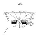
- the voice coil 12which is attached to the coil form 14 , will move in and out of the magnetic gap 16 in response to the alternating power being applied. This interaction may result in cone motion (a.k.a. excursion).
- the voice coil 12is situated between a front plate 22 and a pole piece 24 in the magnetic gap 16 .
- the magnet 26is held into place between front plate 22 and a back plate 28 .
- the vent hole 30allows heat to dissipate, while the dust dome 32 protects the voice coil area from potentially harmful debris.
- Loudspeakersare highly inefficient and convert most of their applied power into heat. A significant component of this heat, which is a function of wasted power over time, is generated in the voice coil 12 . This heat is transferred to the surrounding parts of the loudspeaker, mostly through conduction and convection.
- Types of loudspeaker damageinclude thermal degradation, thermal failure, mechanical failure or a combination thereof.
- Thermal degradationresults from the repeated application of excessive power over a period of time. Repeated overheating of the voice coil 12 leads to damaging thermal-expansion effects and material fatiguing. Such thermal degradation can further lead to thermally-induced mechanical failure since the materials that comprise the voice coil 12 and related components tend to become brittle and are generally more vulnerable to mechanical shock.
- heating of the voice coilwill cause heating of the surrounding materials; overheating of the magnet 26 can irreversibly change its magnetic properties, especially magnets made of rare-earth materials such as neodymium.
- Thermal failurelike thermal degradation, results from the negative heat effects of applying excessive power to a loudspeaker. However, instead of causing gradual degradation, a strong power surge can lead to a catastrophic thermal failure in which the voice coil 12 is heated to the point where it or other components of the loudspeaker literally melt, break or bum.
- Nestorovicdiscloses a method of limiting power to a loudspeaker based on the assumption that the loudspeaker is a fixed resistive load.
- loudspeaker impedanceis not simply a resistive load, but rather varies with frequency and driver temperature. Therefore, the power delivered to the loudspeaker cannot be accurately determined by assuming the loudspeaker is a fixed resistive load.
- von Recklinghausendescribes a method of limiting that uses a model of the loudspeaker.
- the voltage present across the loudspeaker terminalsdrives the loudspeaker model, and the output of the model is compared to a threshold.
- limitingis based solely on the output of the loudspeaker model, which is merely an estimation and not a measurement of power or voice coil temperature.
- Takahashidescribes a method of circuit protection for a power amplifier in which both voltage and current are detected. This method attempts to protect the amplifier from damage when the load impedance is too small. It does not protect the loudspeaker from excessive power or distortion.
- Finkdescribes a method in which both the voltage and current applied to a loudspeaker are measured, and power is calculated as a function of frequency.
- a record of measurement datais stored and a Fourier transformation performed, where the minimum length of this record is dictated by the lowest frequency of interest in the signal. For audio, this lowest frequency is 20 Hz, or a minimum record length of 50 milliseconds. The length of this record severely limits the response time of processing that may occur on the input signal as a result of the measured power output.
- Buttondescribes a system that limits the temperature of a loudspeaker's voice coil by estimating the voice coil temperature and comparing it to a predetermined threshold.
- This systemuses the input signal and a thermal model of the voice coil to estimate the voice coil temperature.
- a thermal modelis inherently susceptible to inaccuracy, because it is an estimation of the voice coil temperature and not an actual measurement.
- One aspect of the inventioninvolves a method that comprises driving the load with an input signal from a power source, providing a power signal that is representative of a power level of the input signal and calculating a value based on said power signal according to one or more control parameters. The method further comprises limiting the input signal based on the value.
- a second aspect of the inventioninvolves mitigation or reduction of degradation of loudspeakers due to thermal effects.
- FIG. 1is a simple schematic of a loudspeaker
- FIG. 2is a simplified diagram of one embodiment of a power limiter, in accordance with the principles of the present invention.
- FIG. 3is a diagram of a second embodiment of the present invention.
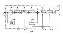
- FIG. 4is a diagram of an embodiment of the control element of FIG. 3 ;
- FIG. 5is a diagram illustrating one embodiment of the attenuation element of FIG. 3 , where attenuation is performed digitally and the attenuated signal is converted to analog using a digital-to-analog converter;
- FIG. 6is a diagram illustrating one embodiment of the attenuation element of FIG. 3 , where attenuation is performed digitally and the attenuated element output is a digital signal;
- FIG. 7is a diagram illustrating one embodiment of the attenuation element of FIG. 3 , where attenuation is performed using a digitally controlled analog signal;
- FIG. 8is one embodiment of a process for limiting power consistent with the principles of the invention.
- FIG. 9is one embodiment of a process for calculating an updated gain value to be used in the process of FIG. 8 ;
- FIG. 10is an illustration of the effect of temperature on loudspeaker impedance versus frequency.
- FIG. 11is a diagram of an embodiment of the control element of FIG. 3 for performing thermal limiting.
- the present inventionrelates to an apparatus and method of limiting the power delivered to a loudspeaker in order to prevent distortion or damage caused by signals of excessive magnitude.
- the techniqueis able to quickly limit the power while minimizing the audible artifacts of the limiting process itself.
- One aspect of the inventionrelates to limiting the true power delivered to a loudspeaker by measuring both voltage and current.
- the poweris actively controlled in response to the measured voltage and current.
- the inventionrelates to limiting the power delivered to a loudspeaker with no prior knowledge of the loudspeaker's characteristics.
- a second aspect of the inventionrelates to an apparatus and method that quickly limits the power applied to a loudspeaker before damage or audible distortion can occur; and in doing so, the limiting process should not generate its own audibly objectionable distortion.
- a third aspect of the inventionprovides the user with independent parameters with which to control the power limiting process. These parameters include but are not limited to (1) power level averaging time, (2) power threshold, (3) attack time, and (4) release time. In one embodiment, the invention allows the user to select between peak power limiting and average power limiting.
- a further aspect of the inventioninvolves limiting the temperature of the voice coil of the loudspeaker before damage to the loudspeaker can occur.
- the temperature of the voice coilwhich is determined by its DC resistance, may be directly calculated from the voltage and current measured at the loudspeaker.
- only the loudspeaker's impedance functionneeds to be known, and the temperature of the voice coil can be determined given any input signal of sufficient magnitude.
- both the voltage and current applied to the loudspeakerare measured. Using both measurements, instantaneous power can be directly calculated as the product of the two and used to control the level of the input to the amplifier in a feedback configuration.
- the temperature of the voice coilis calculated from the measured voltage and current and used to control the level of the input to the amplifier in a feedback configuration. The level of the input may also be controlled quickly enough to prevent damage to the loudspeaker and precisely enough to minimize audibly objectionable artifacts.
- FIG. 2illustrates a simplified version of the present invention.
- Input signal 34is provided to attenuator 36 , the output 38 of which is provided to power amplifier 40 , which drives loudspeaker 46 .
- Voltage monitor circuit 48generates signal 50 that is representative of the voltage present at loudspeaker input 44 .
- Current monitor circuit 42generates signal 52 that is representative of the current flowing through loudspeaker 46 .
- Signals 50 and 52drive control circuit 58 .
- the control circuitgenerates gain value 60 that is used to attenuate input signal 34 when loudspeaker 46 is in danger of being damaged or producing distortion.
- FIG. 3One embodiment of the invention is shown in FIG. 3 .
- the level of input signal 34is adjusted by attenuator 62 , whose output 38 drives power amplifier 40 .
- the output of power amplifier 40passes through current monitor circuit 64 and drives loudspeaker 46 .
- Loudspeaker 46 in this embodimentis representative of a single loudspeaker or a plurality of loudspeakers connected by electrical means.
- the loudspeakermay or may not be connected to a passive crossover network. Current and voltage monitoring may occur before or after this crossover network, if available.
- Current monitor circuit 64generates a voltage that is representative of the current flowing through loudspeaker 46 . This current may be measured as the current that flows from the output of power amplifier 40 to loudspeaker input 44 .
- Analog-to-digital converter 66samples the voltage signal generated by current monitor circuit 64 .
- Voltage monitor circuit 68generates a voltage that is representative of the voltage present at loudspeaker input 44 .
- Analog-to-digital converter 70samples the voltage signal generated by voltage monitor circuit 68 .
- monitoring circuits 64 and 68are not covered by this invention, and it is assumed that their effect on loudspeaker input signal 44 is negligible.
- FIG. 3shows these monitoring circuits as separate from amplifier 40 , but it should equally be appreciated that they may be part of amplifier 40 .
- the outputs of these monitoring circuitsaccurately represent the voltage and current at the output of amplifier 40 .
- the electrical connection between the output of amplifier 40 and loudspeaker 46may have only a negligible effect on the voltage and current at loudspeaker input 44 .
- Monitoring circuits 64 and 68scale the magnitudes of the voltages they generate so that analog-to-digital converters 66 and 70 may sample them. Any DC offset that is present may be removed from outputs 52 and 50 of analog-to-digital converters 66 and 70 , respectively.
- analog-to-digital converters 66 and 70sample their inputs at greater than or equal to the Nyquist rate, or at a rate that is twice the highest frequency present in output signal 44 .
- the scope of this inventionis not limited to sampling at the Nyquist rate. If the voltage and current monitor signals are subsampled (sampled at less than the Nyquist rate), aliasing may occur. In this case, the instantaneous power is calculated as the product of the subsampled voltage and the subsampled current. Subsampling does not alter the average power measurement of the sampled signal; therefore, limiting the average power output based on a subsampled instantaneous power measurement is valid. It may be necessary to modulate the sampling frequency in order to accurately detect frequencies that would otherwise be an integer multiple of the sampling frequency. One embodiment will modulate the sampling frequency randomly or pseudo-randomly between specified lower and upper boundary frequencies.
- Signals 50 and 52which are representative of the voltage and current present at the loudspeaker, are provided as inputs to control element 58 .
- User-input control parameters 72may be used to determine the behavior of control element 58 .
- user-input control parameters 72are provided as a library of user-input control parameters 72 .
- the librarymay contain user-input control parameters 72 that have been optimized for particular loudspeakers, and these optimized control parameters 72 may be accessed by selecting a corresponding loudspeaker from a list of available loudspeakers.
- a usermay manually set the user-input control parameters 72 .
- the library of control parameters or user-selected parametersmay be accessed through a graphical user interface.
- Gain value 60may be provided as an input to attenuator 62 , which adjusts the level of input signal 34 .
- control element 58may be implemented as firmware, software or hardware.
- the control element 58may be implemented as a linear or nonlinear gain control element. It may also be implemented as a recursive or non-recursive gain control element.
- Multiplier 54calculates the instantaneous power measurement as the product of signals 50 and 52 , which are representative of the voltage and current, respectively.
- the power levelis calculated by averaging filter 74 from the output of multiplier 54 .
- averaging filter 74is a second-order recursive filter.
- two first-order low-pass filtersare cascaded to produce the second-order averaging filter.
- the scope of this inventionencompasses other types of level measurements including but not limited to recursive averaging of any order and filter type, nonrecursive (transversal) averaging, and combination peak/average measurements.
- the averaging time of averaging filter 74is set to zero, in effect bypassing the averaging filter, gain reduction may be calculated based on peak power. Setting the averaging time to greater than zero results in limiting of the average power over the time specified by averaging coefficient 92 . In this implementation, therefore, either peak power or average power may be limited. In one embodiment, the averaging time is greater than or equal to 50 milliseconds for average power limiting over the audio range of frequencies.
- the average power level (L), the output of averaging filter 74 ,is processed by gain calculation element 76 .
- the gain calculation element 76calculates the gain such that the input signal is attenuated by an appropriate amount when the average power level (L) exceeds threshold 94 , P T .
- a I and A Vare correction factors for the respective gains of current monitor circuit 64 and voltage monitor circuit 68
- Lis the output of averaging filter 74 .
- the scope of this inventionencompasses other types of control, including but not limited to linear or nonlinear gain control, and piecewise linear or piecewise nonlinear gain control.
- Multiplier 78calculates the product of the output of gain calculation element 76 and the output of averaging filter 90 .
- the output of multiplier 78is provided to gain processing element 80 .
- gain processing element 80inverts the gain value such that its output is a measure of gain reduction and constrains the value such that it is non-negative.
- peak detector 82calculates the peak gain reduction from the output of gain processing element 80 .
- the purpose of the peak filteris to maintain the gain reduction level over a user specified release time.
- a peak filteris a recursive low-pass filter that stores the maximum of its input and output as feedback to the next sample cycle.
- the third-order filtermay be constructed by cascading three first-order filter sections. Each filter section compares its input and output and stores the maximum as feedback to the next sample cycle.
- the output of peak detector 82should not be allowed to change too rapidly, or its nonlinear effect on attenuated input signal 38 would be audible. Therefore, the output of peak detector 82 is smoothed by smoothing filter 84 .
- a second-order Bessel-Thomson filtermay be used for smoothing filter 84 , although any order or type of filter is within the scope of this invention.
- the Bessel-Thomson filteris used to prevent overshoot of the smoothed gain value during transition.
- a second-order filterwas chosen because it adequately attenuates higher-order harmonics in the non-linear output of peak detector 82 . If insufficiently attenuated, these higher-order harmonics would modulate the input signal at attenuator 62 , resulting in audible aliasing.
- cascaded first-order filtersmay be used for smoothing filter 84 . Although this results in a greater group delay than the Bessel-Thomson filter, it may be simpler to implement and will not result in overshoot of the smoothed gain value.
- smoothing filter 84determines the minimum time in which the onset of gain reduction can occur. This time is specified as the attack time.
- the attack timeis the amount of time required for gain value 60 to change by a specified amount, given that the output of gain calculation element 76 instantaneously changes from no gain reduction to the steady state destination value.
- the attack timemay also be defined as the time constant of smoothing filter 84 .
- the attack timedetermines smoothing coefficient 98 , T S .
- the minimum release timeis equal to the attack time. In other words, the release time cannot be less than the attack time.
- This constraintis acceptable in the vast majority of audio applications, and this embodiment is preferred over one that uses a single switched filter that determines both attack and release characteristics.
- a single switched filterwould have a time constant that is switched between attack and release times, depending on the slope of the input to this filter.
- This switched filteris inherently nonlinear, and would produce aliasing in attenuator output 38 .
- the placement of a linear smoothing filter at the end of the control signal path as described by the present inventiongreatly reduces audible aliasing.
- Gain inversion element 86converts the output of smoothing filter 84 , which is a measure of gain reduction, into gain value 60 .
- Gain value 60is also provided back into multiplier 78 through loop filter 88 and averaging filter 90 .
- Averaging filter 90is designed to mimic averaging filter 74 , and therefore has the same averaging time 92 .
- loop filter 88is designed to mimic the effect of the remainder of the feedback path: gain value 60 , which is applied to signal input 34 , which is amplified by amplifier 40 , whose current and voltage are monitored by circuits 64 and 68 , whose outputs are sampled by analog-to-digital converters 66 and 70 .
- loop filter 88is a simple delay whose delay time is equal to that of the previously described feedback path.
- the sample rate of the control signalmay be decimated at any point after averaging filter 74 . Such decimation may reduce the amount of computation.
- the control signalcan be interpolated by smoothing filter 84 , restoring the sample rate to its previous value.
- Gain value 60is provided to attenuator 62 , where it controls the level of the input to amplifier 40 .
- Attenuator 62is shown in FIG. 5 .
- Analog-to-digital converter 100samples input signal 34 .
- Multiplier 102calculates the product of the sampled input and gain value 60 .
- the output of multiplier 102is converted to analog output 38 by digital-to-analog converter 104 .
- Analog output 38is amplified by amplifier 40 of FIG. 3 .
- a second embodiment of attenuator 62is shown in FIG. 6 .
- Analog-to-digital converter 100samples input signal 34 .
- Multiplier 102calculates the product of the sampled input and gain value 60 .
- Digital output 38is modulated and amplified by amplifier 40 of FIG. 3 .
- the type of modulation in this embodimentmay be pulse-width modulation, sigma-delta modulation, a variation of one of these techniques, or any other type of digital modulation technique.
- input signal 34may be delivered in digital form using a digital transmission medium.
- analog-to-digital converter 100is present at some point in the signal chain before multiplier 102 .
- analog-to-digital converter 100may be omitted without altering the scope of this invention.
- FIG. 8A third embodiment of attenuator 62 is shown in FIG. 8 .
- Input 34is provided to digitally-controlled analog attenuator 108 , which is controlled by gain value 60 .
- Analog output 38is amplified by amplifier 40 of FIG. 3 .
- additional signal processingmay occur before or after multiplier 102 or attenuator 108 .
- the inventionmay be extended to a multi-channel power limiter.
- Each channelconsists of an input 34 that is provided to attenuator 62 , which feeds amplifier 40 , which in turn drives loudspeaker 46 .
- Current monitor circuit 64generates a voltage representative of the current that flows through loudspeaker 46 , which is sampled by analog-to-digital converter 66 .
- Voltage monitor circuit 68generates a voltage representative of the voltage at loudspeaker input 44 , which is sampled by analog-to-digital converter 70 .
- Digital current signal 52 and digital voltage signal 50are provided to multiplier 54 , which calculates the instantaneous power 56 .
- the maximum instantaneous power of all the channelsis chosen as the input to control element 58 .
- This control elementis common to all channels.
- Other combinations of the channels, such as the maximum of all channels' average power, or the average of all channels' power measurements,are within the scope of this invention.
- the remainder of the control pathis equivalent to that of FIG. 4 .
- Resultant gain 60is used on all channels to prevent the virtual audio image from shifting.
- process 200begins with an input signal being provided to an attenuator at block 202 .
- the input signalis input signal 34 , which is being provided to attenuator 62 .
- the attenuatormay then regulate the level of the input signal according to a current gain value (block 204 ).
- the attenuatormay be used to drive an amplifier (e.g., amplifier 40 ) with the attenuated input signal (e.g., output 38 ).
- the amplifiermay then provide power to a connected loudspeaker.
- a current monitor and voltage monitormay be used to measure the amplifier's current level and voltage level, respectively.
- the current monitoris current monitor circuit 64 and the voltage monitor is voltage monitor circuit 68 .
- Process 200may then continue to block 210 where the current monitor and voltage monitor generate representative signals of the current and voltage levels being provided to the loudspeaker. These signals may then be used to calculate an updated gain value, which in one embodiment is calculated according to the process discussed below with reference to FIG. 9 .
- the updated gain valuemay then be supplied back to attenuator block 204 , which in turn, may adjust the level of attenuation based on the updated gain signal.
- the process 218 for calculating the updated gain value of block 214begins at blocks 220 and 222 , when the respective voltage and current measurements are received by a control block (e.g., control element 58 ).
- Process 218then calculates the instantaneous power at block 224 . From this instantaneous power, process 218 calculates a signal representative of the power level (block 226 ). In one embodiment, this representative signal level is calculated by averaging filter 74 . While in another embodiment the representative signal level is an averaged measurement of the power signal, such as one of the averaging measurements discussed above with reference to FIG. 4 , it should also be appreciated that the representative signal level may be a peak measurement. In yet another embodiment, averaging coefficient T A may be used to calculate the representative signal level of block 226 .
- the representative signal level and predetermined power thresholdare used to calculate a gain value.
- This calculated gain valueis representative of the additional gain required at block 204 (e.g., attenuator 62 ) to achieve an attenuated signal level equal to the predetermined power threshold.
- this user input power thresholdis P T .
- the gain value calculationproceeds according to Equation 2.
- the gain value previously calculated at block 244is supplied to block 230 .
- This gain valueis processed by a filter that mimics the response of the loop, or the signal path between the output of block 214 and the input of block 214 .
- this filteris a pure delay.
- Process 218may then continue to block 232 where the average value of the filtered gain value is calculated. In one embodiment, this average is calculated in the same manner as that of block 226 .
- Process 218may then continue to block 234 where the additional gain value calculated by block 228 is multiplied by the average of the previous gain value supplied by block 232 .
- the resulting valueis the gain required at block 204 (e.g., attenuator 62 ) to achieve an attenuated signal level equal to the predetermined power threshold.
- the output gain of block 234is constrained and inverted at block 236 , such that the output value is between 0 and 1 and is equal to 1 minus the input value.
- block 238calculates the peak level of the gain reduction, which maintains the gain reduction level for a specified period of time.
- the specified period of timeis a function of release coefficient T P .
- the gain reduction value calculated at block 238may be smoothed using a smoothing filter, such as smoothing filter 84 . Afterwards, the smoothed gain reduction value is re-inverted at block 242 to yield a gain value. This inversion process may be equivalent to that of block 234 . Finally, at block 244 of process 218 , the resultant smoothed gain value may then be supplied to a signal attenuator (e.g., attenuator 62 ) as an updated gain value.
- a signal attenuatore.g., attenuator 62
- R Eis the only temperature-dependent component of the equivalent electrical circuit of a loudspeaker. This means that the loudspeaker's impedance as a function of frequency, Z( ⁇ ), will shift upward with an increase in temperature, while its shape is generally unchanged.
- loudspeakerrefers to a loudspeaker mounted in an enclosure.
- FIG. 10An illustration of this change in loudspeaker impedance with temperature is shown in FIG. 10 .
- port compressiona phenomenon known as port compression, which results when a loudspeaker in a ported enclosure is driven at high sound pressure levels. As the drive level of this loudspeaker is increased, the acoustic output at the port frequency increases proportionally less; and at high enough drive levels, the acoustic output actually decreases. This compression effect is evident in the loudspeaker's equivalent electrical impedance function and must be compensated for.
- the current that flows through the loudspeakeris a function of the impedance of the loudspeaker and the voltage applied to it.
- this currentmay be modeled as the output of an admittance function, A( ⁇ ), where the voltage applied to the loudspeaker is the input to A( ⁇ ).
- A( ⁇ )is a function of frequency and is the reciprocal of the loudspeaker's impedance function.
- A( ⁇ )may be determined at ambient temperature T 0 such that A( ⁇ ) does not change with temperature. With the measured voltage from the loudspeaker as input to A( ⁇ ), the temperature-invariant contribution to the current flowing through the loudspeaker may be estimated.
- A( ⁇ )may be a function of the power applied to the loudspeaker, as is the case in loudspeaker port compression.
- R E R 0Dividing a temperature-invariant estimation of the current by the measured current from the loudspeaker results in R E R 0 , which is the only temperature-dependent portion of the loudspeaker's impedance. This estimate can be made for any signal applied to the loudspeaker; therefore, the change in voice coil resistance under normal operating conditions can be measured. The exception to this is when there is insufficient input level to make an accurate measurement; however, under these conditions, the voice coil is not susceptible to overheating. The level of the measured current and modeled current may be averaged to minimize differences due to deficiencies in A( ⁇ ).
- the maximum change in resistance of the voice coilcan be calculated from Equation (4). By comparing this threshold value with an estimated change in voice coil resistance, R E R 0 , the point at which the applied power should be reduced can be determined. Reducing the power applied to the loudspeaker will lower the temperature of the voice coil.
- Equation (4)Since ⁇ in Equation (4) is typically small, the change in voice coil resistance is nearly linearly related to the change in temperature. Therefore, the gain reduction calculation can be based on R E R 0 , resulting in an appropriate change in voice coil temperature.
- FIG. 11shows control element 58 , which has been adapted to limit the power applied to loudspeaker 46 based on the temperature of its voice coil 12 .
- Signals 50 and 52which are representative of the voltage and current present at the loudspeaker, are provided as inputs to control element 58 .
- Representative voltage signal 50is supplied to admittance function 100 , which mimics the electrical admittance of loudspeaker 46 .
- the output of admittance function 100is supplied to averaging function 75 , which produces the average level of its input.
- averaging function 75is an absolute value function followed by a first-order recursive averaging filter.
- Representative current signal 52is supplied to a second averaging function 75 . Both averaging functions 75 are identical and have averaging time specified by coefficient 92 , T A .
- the average level of the measured current, I, and the average level of the modeled current, I 0are provided to gain calculation element 77 , which calculates the additional gain required for the DC resistance of the voice coil of loudspeaker 46 to be reduced to prescribed threshold value 95 , R T R 0 .
- Prescribed threshold value 95is calculated by Equation (6), where T T is the threshold temperature of the voice coil in Celsius.
- R T R 01 + ⁇ ⁇ ( T T - T 0 ) + ⁇ ⁇ ( T T - T 0 ) 2 ( 6 )
- Gain calculation element 77calculates its result in Equation (7), where A I and A V are the respective gains of the current and voltage monitoring circuits described previously.
- control element 58 in FIG. 11is identical to that of FIG. 4 , with the exception of averaging function 75 , which has been described previously.
Landscapes
- Engineering & Computer Science (AREA)
- Power Engineering (AREA)
- Multimedia (AREA)
- Physics & Mathematics (AREA)
- Acoustics & Sound (AREA)
- Signal Processing (AREA)
- Circuit For Audible Band Transducer (AREA)
- Amplifiers (AREA)
Abstract
Description
where n is the filter order, tais the averaging time in seconds, and fSis the sampling frequency in Hz. The scope of this invention encompasses other types of level measurements including but not limited to recursive averaging of any order and filter type, nonrecursive (transversal) averaging, and combination peak/average measurements.
is dependent only upon its change in temperature and may be found by the following expression:
where REis the DC resistance of the voice coil at operating temperature T, R0is the DC resistance of the voice coil at ambient temperature T0(typically 25 Celsius), and α and β are the thermal coefficients of resistance for the material from which the voice coil is made (typically copper or aluminum). In addition, it is generally accepted that REis the only temperature-dependent component of the equivalent electrical circuit of a loudspeaker. This means that the loudspeaker's impedance as a function of frequency, Z(ω), will shift upward with an increase in temperature, while its shape is generally unchanged. (In this context, the term loudspeaker refers to a loudspeaker mounted in an enclosure.) An illustration of this change in loudspeaker impedance with temperature is shown in FIG.10.
from which the increase in voice coil temperature may be determined. Since the voltage driving the loudspeaker is unchanged by the loudspeaker's impedance, only the current flowing through the loudspeaker changes. Thus, only the change in current is needed to determine the change in temperature:
One exception to this is a phenomenon known as port compression, which results when a loudspeaker in a ported enclosure is driven at high sound pressure levels. As the drive level of this loudspeaker is increased, the acoustic output at the port frequency increases proportionally less; and at high enough drive levels, the acoustic output actually decreases. This compression effect is evident in the loudspeaker's equivalent electrical impedance function and must be compensated for.

A(ω) is a function of frequency and is the reciprocal of the loudspeaker's impedance function. For present purposes, A(ω) may be determined at ambient temperature T0such that A(ω) does not change with temperature. With the measured voltage from the loudspeaker as input to A(ω), the temperature-invariant contribution to the current flowing through the loudspeaker may be estimated. Note that A(ω) may be a function of the power applied to the loudspeaker, as is the case in loudspeaker port compression.
which is the only temperature-dependent portion of the loudspeaker's impedance. This estimate can be made for any signal applied to the loudspeaker; therefore, the change in voice coil resistance under normal operating conditions can be measured. The exception to this is when there is insufficient input level to make an accurate measurement; however, under these conditions, the voice coil is not susceptible to overheating. The level of the measured current and modeled current may be averaged to minimize differences due to deficiencies in A(ω).
the point at which the applied power should be reduced can be determined. Reducing the power applied to the loudspeaker will lower the temperature of the voice coil.
resulting in an appropriate change in voice coil temperature.
Gain calculation element77 calculates its result in Equation (7), where AIand AVare the respective gains of the current and voltage monitoring circuits described previously.
The remainder of
Claims (20)
Priority Applications (3)
| Application Number | Priority Date | Filing Date | Title |
|---|---|---|---|
| US10/665,192US6940981B2 (en) | 2003-03-12 | 2003-09-16 | Apparatus and method of limiting power applied to a loudspeaker |
| PCT/US2004/006527WO2004082322A2 (en) | 2003-03-12 | 2004-03-04 | Apparatus and method of limiting power applied to a loudspeaker |
| US11/087,427US7436967B2 (en) | 2003-03-12 | 2005-03-23 | Apparatus and method of limiting power applied to a loudspeaker |
Applications Claiming Priority (2)
| Application Number | Priority Date | Filing Date | Title |
|---|---|---|---|
| US45427103P | 2003-03-12 | 2003-03-12 | |
| US10/665,192US6940981B2 (en) | 2003-03-12 | 2003-09-16 | Apparatus and method of limiting power applied to a loudspeaker |
Related Child Applications (1)
| Application Number | Title | Priority Date | Filing Date |
|---|---|---|---|
| US11/087,427ContinuationUS7436967B2 (en) | 2003-03-12 | 2005-03-23 | Apparatus and method of limiting power applied to a loudspeaker |
Publications (2)
| Publication Number | Publication Date |
|---|---|
| US20040178852A1 US20040178852A1 (en) | 2004-09-16 |
| US6940981B2true US6940981B2 (en) | 2005-09-06 |
Family
ID=32965715
Family Applications (2)
| Application Number | Title | Priority Date | Filing Date |
|---|---|---|---|
| US10/665,192Expired - LifetimeUS6940981B2 (en) | 2003-03-12 | 2003-09-16 | Apparatus and method of limiting power applied to a loudspeaker |
| US11/087,427Expired - LifetimeUS7436967B2 (en) | 2003-03-12 | 2005-03-23 | Apparatus and method of limiting power applied to a loudspeaker |
Family Applications After (1)
| Application Number | Title | Priority Date | Filing Date |
|---|---|---|---|
| US11/087,427Expired - LifetimeUS7436967B2 (en) | 2003-03-12 | 2005-03-23 | Apparatus and method of limiting power applied to a loudspeaker |
Country Status (2)
| Country | Link |
|---|---|
| US (2) | US6940981B2 (en) |
| WO (1) | WO2004082322A2 (en) |
Cited By (17)
| Publication number | Priority date | Publication date | Assignee | Title |
|---|---|---|---|---|
| US20050249353A1 (en)* | 2004-05-05 | 2005-11-10 | Visteon Global Technologies, Inc. | System and method for detecting fault conditions on audio output channels |
| US20060176046A1 (en)* | 2005-02-07 | 2006-08-10 | Walker Jason A | Power meter for biasing an audio amplifier |
| US20060181351A1 (en)* | 2005-02-17 | 2006-08-17 | Skyworks Solutions, Inc. | Power control circuit for accurate control of power amplifier output power |
| US20100290643A1 (en)* | 2009-05-18 | 2010-11-18 | Harman International Industries, Incorporated | Efficiency optimized audio system |
| US20110116648A1 (en)* | 2009-11-16 | 2011-05-19 | Harwell Samuel C | Prevention of hearing loss from audio devices |
| US20110194705A1 (en)* | 2010-02-10 | 2011-08-11 | Nxp B.V. | System and method for adapting a loudspeaker signal |
| US20110193578A1 (en)* | 2010-02-08 | 2011-08-11 | Nxp B.V. | System and method for sensing an amplifier load current |
| US20120121098A1 (en)* | 2010-11-16 | 2012-05-17 | Nxp B.V. | Control of a loudspeaker output |
| CN103873985A (en)* | 2012-12-13 | 2014-06-18 | 马克西姆综合产品公司 | Direct measurement of input signal to loudspeaker to determine and limit temperature of voice coil of the loudspeaker |
| US8774419B2 (en) | 2011-09-28 | 2014-07-08 | Texas Instruments Incorporated | Thermal control of voice coils in loudspeakers |
| US20150207471A1 (en)* | 2014-01-21 | 2015-07-23 | Robert Bosch Gmbh | Amplifier arrangement with limiting module |
| US9131302B2 (en) | 2012-06-11 | 2015-09-08 | Apple Inc. | Speaker temperature control using speaker temperature and speaker impedance estimates |
| US20160249135A1 (en)* | 2015-02-20 | 2016-08-25 | Dialog Semiconductor (Uk) Limited | Optimised Loudspeaker Operation |
| US9525939B2 (en) | 2014-10-10 | 2016-12-20 | Analog Devices Global | Overheat protector and protection methodology for electrodynamic loudspeakers |
| US9917554B2 (en) | 2011-06-22 | 2018-03-13 | Nxp B.V. | Control of a loudspeaker output |
| US11329610B2 (en)* | 2019-11-07 | 2022-05-10 | Chung-Fu Chou | Structure and method of audio amplifier with power feedback |
| US11545941B2 (en)* | 2020-02-26 | 2023-01-03 | Jose Mazini Tarifa | Electronic system of active power control for automotive audio amplifiers |
Families Citing this family (64)
| Publication number | Priority date | Publication date | Assignee | Title |
|---|---|---|---|---|
| US6856199B2 (en)* | 2000-10-10 | 2005-02-15 | California Institute Of Technology | Reconfigurable distributed active transformers |
| KR100852315B1 (en) | 2000-10-10 | 2008-08-14 | 캘리포니아 인스티튜트 오브 테크놀로지 | Power amplifiers and methods thereof, and inductors |
| TWI326967B (en) | 2002-03-11 | 2010-07-01 | California Inst Of Techn | Differential amplifier |
| US20070217625A1 (en)* | 2006-03-06 | 2007-09-20 | National Chiao Tung University | Loudspeaker system having sensorless bass compensation |
| DE102006039162A1 (en)* | 2006-08-21 | 2008-02-28 | Lear Corp., Southfield | Protection method for speaker systems |
| WO2008092111A2 (en)* | 2007-01-26 | 2008-07-31 | Jm Electronics Ltd. Llc | Drivers and methods for driving a load |
| US8019292B2 (en)* | 2007-07-11 | 2011-09-13 | Axiom Microdevices, Inc. | Power amplifier amplitude modulator system and method |
| DE102007032281A1 (en)* | 2007-07-11 | 2009-01-15 | Austriamicrosystems Ag | Reproduction device and method for controlling a reproduction device |
| US7710197B2 (en) | 2007-07-11 | 2010-05-04 | Axiom Microdevices, Inc. | Low offset envelope detector and method of use |
| US8259953B2 (en)* | 2008-04-10 | 2012-09-04 | Bang & Olufsen Icepower A/S | Thermal protection of electro dynamic transducers used in loudspeaker systems |
| US20090257601A1 (en)* | 2008-04-12 | 2009-10-15 | Marvin Andrew Motsenbocker | Acoustic speaker system with strong bass capability |
| US8712065B2 (en)* | 2008-04-29 | 2014-04-29 | Bang & Olufsen Icepower A/S | Transducer displacement protection |
| US8150273B2 (en)* | 2008-09-04 | 2012-04-03 | Finisar Corporation | Optical receiver with threshold voltage compensation |
| US7994857B2 (en)* | 2009-12-23 | 2011-08-09 | Rockford Corporation | Dynamic constant power amplifier |
| US8750525B2 (en)* | 2010-01-28 | 2014-06-10 | Harris Corporation | Method to maximize loudspeaker sound pressure level with a high peak to average power ratio audio source |
| EP2398253A1 (en)* | 2010-06-16 | 2011-12-21 | Nxp B.V. | Control of a loudspeaker output |
| CN101877807B (en)* | 2010-06-18 | 2015-08-12 | 中兴通讯股份有限公司 | The method that loud speaker and source of sound are play |
| CN101986721B (en)* | 2010-10-22 | 2014-07-09 | 苏州上声电子有限公司 | Fully digital loudspeaker device |
| EP2469708B1 (en)* | 2010-12-21 | 2013-11-27 | Harman Becker Automotive Systems GmbH | Amplifier current consumption control |
| US9154101B2 (en)* | 2011-06-24 | 2015-10-06 | Fairchild Semiconductor Corporation | Active audio transducer protection |
| CN102892058A (en)* | 2011-07-18 | 2013-01-23 | 中兴通讯股份有限公司 | Method and device for automatically regulating volume |
| US9347835B2 (en) | 2011-08-17 | 2016-05-24 | Cirrus Logic, Inc. | Systems and methods for peak junction temperature sensing and thermal safe operating area protection |
| US20130077796A1 (en)* | 2011-09-28 | 2013-03-28 | Texas Instruments Incorporated | Thermal Protection for Loudspeakers |
| US20130077795A1 (en)* | 2011-09-28 | 2013-03-28 | Texas Instruments Incorporated | Over-Excursion Protection for Loudspeakers |
| DE102011054060B4 (en)* | 2011-09-29 | 2017-09-21 | D&B Audiotechnik Gmbh | AUDIO AMPLIFIER |
| WO2013075727A1 (en)* | 2011-11-22 | 2013-05-30 | Andrew Wireless Systems Gmbh | Adaptive supply voltage for a power amplifier |
| JP5849677B2 (en)* | 2011-12-15 | 2016-02-03 | 船井電機株式会社 | Audio output device |
| US9306525B2 (en)* | 2012-06-08 | 2016-04-05 | Apple Inc. | Combined dynamic processing and speaker protection for minimum distortion audio playback loudness enhancement |
| EP2876895B1 (en)* | 2012-07-23 | 2017-07-05 | Yamaha Corporation | Temperature measurement device and protective device for audio signal converter |
| FR2995167B1 (en)* | 2012-08-30 | 2014-11-14 | Parrot | METHOD FOR PROCESSING AN AUDIO SIGNAL WITH MODELING OF THE GLOBAL RESPONSE OF THE ELECTRODYNAMIC SPEAKER |
| EP2712209B1 (en)* | 2012-09-21 | 2021-01-13 | Dialog Semiconductor BV | Method and apparatus for computing metric values for loudspeaker protection |
| US9729986B2 (en) | 2012-11-07 | 2017-08-08 | Fairchild Semiconductor Corporation | Protection of a speaker using temperature calibration |
| US10219090B2 (en) | 2013-02-27 | 2019-02-26 | Analog Devices Global | Method and detector of loudspeaker diaphragm excursion |
| JP6478910B2 (en) | 2013-07-25 | 2019-03-06 | 株式会社 Trigence Semiconductor | Speaker control device |
| US9980068B2 (en)* | 2013-11-06 | 2018-05-22 | Analog Devices Global | Method of estimating diaphragm excursion of a loudspeaker |
| GB2522449B (en) | 2014-01-24 | 2016-07-13 | Cirrus Logic Int Semiconductor Ltd | Loudspeaker protection systems and methods |
| TWI592034B (en)* | 2014-03-14 | 2017-07-11 | 瑞昱半導體股份有限公司 | Audio apparatus with thermal controlling ability and the controlling method thereof |
| US9462381B2 (en)* | 2014-05-28 | 2016-10-04 | Apple Inc. | Intelligent dynamics processing |
| GB2526881B (en)* | 2014-06-06 | 2017-10-04 | Cirrus Logic Int Semiconductor Ltd | Temperature monitoring for loudspeakers |
| US9813812B2 (en) | 2014-12-12 | 2017-11-07 | Analog Devices Global | Method of controlling diaphragm excursion of electrodynamic loudspeakers |
| FR3030983B1 (en)* | 2014-12-19 | 2018-02-16 | STMicroelectronics (Alps) SAS | SYSTEM AND METHOD FOR AUDIO SPEAKER PROTECTION |
| FR3031854B1 (en)* | 2015-01-19 | 2017-02-17 | Devialet | DEVICE FOR CONTROLLING A LOUDSPEAKER WITH CURRENT LIMITATION |
| GB2534949B (en)* | 2015-02-02 | 2017-05-10 | Cirrus Logic Int Semiconductor Ltd | Loudspeaker protection |
| CN105050019B (en)* | 2015-06-01 | 2018-03-23 | 歌尔股份有限公司 | The method and system of electro-acoustic conversion device amplitude and temperature parameter are verified simultaneously |
| EP3121961B1 (en) | 2015-07-24 | 2019-04-03 | Nxp B.V. | Temperature sensing |
| US9749739B2 (en)* | 2015-09-18 | 2017-08-29 | Qualcomm Incorporated | Protection of a speaker from thermal damage |
| ITUB20155535A1 (en)* | 2015-11-12 | 2017-05-12 | Istituto Naz Di Geofisica E Vulcanologia | Device for amplification of an audio signal |
| WO2017141292A1 (en)* | 2016-02-17 | 2017-08-24 | パナソニックIpマネジメント株式会社 | Audio reproduction device |
| US10123143B2 (en)* | 2016-09-26 | 2018-11-06 | Cirrus Logic, Inc. | Correction for speaker monitoring |
| US10701484B2 (en)* | 2017-03-22 | 2020-06-30 | Synaptics Incorporated | Non-linear feedback control for temperature and power protection of loudspeakers |
| GB2563460B (en)* | 2017-06-15 | 2021-07-14 | Cirrus Logic Int Semiconductor Ltd | Temperature monitoring for loudspeakers |
| KR102388712B1 (en)* | 2017-11-01 | 2022-04-21 | 삼성전자주식회사 | An electronic device comprising an speaker |
| CN110120226B (en)* | 2018-02-06 | 2021-09-03 | 成都鼎桥通信技术有限公司 | Private network cluster terminal voice tail noise elimination method and device |
| CN111010650B (en) | 2018-10-06 | 2022-02-11 | 华为技术有限公司 | A kind of audio signal processing method, device and equipment |
| TWI698130B (en)* | 2018-12-20 | 2020-07-01 | 瑞昱半導體股份有限公司 | Temperature sensing parameter providing circuit, temperature sensing parameter providing method and temperature monitoring method |
| CN109600705B (en)* | 2019-01-08 | 2021-01-26 | 武汉市聚芯微电子有限责任公司 | Loudspeaker life test system |
| JP7674259B2 (en)* | 2019-04-01 | 2025-05-09 | ボーズ・コーポレーション | Noise reduction signal saturation control |
| US11184705B2 (en) | 2019-11-01 | 2021-11-23 | Synaptics Incorporated | Protection of speaker from excess excursion |
| US11399247B2 (en)* | 2019-12-30 | 2022-07-26 | Harman International Industries, Incorporated | System and method for providing advanced loudspeaker protection with over-excursion, frequency compensation and non-linear correction |
| US11706565B2 (en)* | 2021-02-23 | 2023-07-18 | Meta Platforms Technologies, Llc | Audio source amplification with speaker protection features and internal voltage and current sensing |
| IT202100007736A1 (en) | 2021-03-30 | 2022-09-30 | Vr Tourism S R L | SEMI-AMPLIFIED HI-FI SPEAKER FOR ELECTRIC AND/OR ACOUSTIC BASS |
| US11757420B2 (en)* | 2021-05-19 | 2023-09-12 | Elite Semiconductor Microelectronics Technology Inc. | Method for dynamically adjusting adjustable gain value to equalize input signal to generate equalizer output signal and associated leveling equalizer |
| CN115022775B (en)* | 2022-08-04 | 2023-07-07 | 荣耀终端有限公司 | Driving circuit, terminal equipment and protection method |
| WO2025192208A1 (en)* | 2024-03-13 | 2025-09-18 | ソニーグループ株式会社 | Speaker-installed device and speaker output control method |
Citations (13)
| Publication number | Priority date | Publication date | Assignee | Title |
|---|---|---|---|---|
| US4296278A (en)* | 1979-01-05 | 1981-10-20 | Altec Corporation | Loudspeaker overload protection circuit |
| US4301330A (en)* | 1979-09-28 | 1981-11-17 | Zenith Radio Corporation | Loudspeaker protection circuit |
| US5170437A (en)* | 1990-10-17 | 1992-12-08 | Audio Teknology, Inc. | Audio signal energy level detection method and apparatus |
| US5249225A (en)* | 1991-10-25 | 1993-09-28 | Coherent Communications Systems Corp. | Self-balancing hybrid using digitally programmable attenuator for variable impedance elements |
| US5369711A (en)* | 1990-08-31 | 1994-11-29 | Bellsouth Corporation | Automatic gain control for a headset |
| US5396562A (en)* | 1991-09-10 | 1995-03-07 | Pioneer Electronic Corporation | Signal processing circuit for audio apparatus |
| US5577126A (en)* | 1993-10-27 | 1996-11-19 | Klippel; Wolfgang | Overload protection circuit for transducers |
| US5719526A (en)* | 1994-11-09 | 1998-02-17 | Crest Audio, Inc. | Internal load monitor for amplifier |
| US5729611A (en)* | 1996-02-02 | 1998-03-17 | Bonneville; Marc Etienne | Loudspeader overload protection |
| US5847610A (en)* | 1995-12-05 | 1998-12-08 | Yamaha Corporation | Protection circuit for an audio amplifier |
| US5854845A (en)* | 1992-12-31 | 1998-12-29 | Intervoice Limited Partnership | Method and circuit for voice automatic gain control |
| US6580318B2 (en)* | 2001-03-08 | 2003-06-17 | Maxim Integrated Products, Inc. | Method and apparatus for protecting radio frequency power amplifiers |
| US6628788B2 (en)* | 2000-04-27 | 2003-09-30 | Becker Gmbh | Apparatus and method for noise-dependent adaptation of an acoustic useful signal |
Family Cites Families (3)
| Publication number | Priority date | Publication date | Assignee | Title |
|---|---|---|---|---|
| JPS53162647U (en) | 1977-05-25 | 1978-12-20 | ||
| US4233566A (en) | 1978-10-23 | 1980-11-11 | Technical Audio Products Corporation | Distortion free power limiting and clipping prevention circuit |
| US4327250A (en) | 1979-05-03 | 1982-04-27 | Electro Audio Dynamics Inc. | Dynamic speaker equalizer |
- 2003
- 2003-09-16USUS10/665,192patent/US6940981B2/ennot_activeExpired - Lifetime
- 2004
- 2004-03-04WOPCT/US2004/006527patent/WO2004082322A2/enactiveApplication Filing
- 2005
- 2005-03-23USUS11/087,427patent/US7436967B2/ennot_activeExpired - Lifetime
Patent Citations (13)
| Publication number | Priority date | Publication date | Assignee | Title |
|---|---|---|---|---|
| US4296278A (en)* | 1979-01-05 | 1981-10-20 | Altec Corporation | Loudspeaker overload protection circuit |
| US4301330A (en)* | 1979-09-28 | 1981-11-17 | Zenith Radio Corporation | Loudspeaker protection circuit |
| US5369711A (en)* | 1990-08-31 | 1994-11-29 | Bellsouth Corporation | Automatic gain control for a headset |
| US5170437A (en)* | 1990-10-17 | 1992-12-08 | Audio Teknology, Inc. | Audio signal energy level detection method and apparatus |
| US5396562A (en)* | 1991-09-10 | 1995-03-07 | Pioneer Electronic Corporation | Signal processing circuit for audio apparatus |
| US5249225A (en)* | 1991-10-25 | 1993-09-28 | Coherent Communications Systems Corp. | Self-balancing hybrid using digitally programmable attenuator for variable impedance elements |
| US5854845A (en)* | 1992-12-31 | 1998-12-29 | Intervoice Limited Partnership | Method and circuit for voice automatic gain control |
| US5577126A (en)* | 1993-10-27 | 1996-11-19 | Klippel; Wolfgang | Overload protection circuit for transducers |
| US5719526A (en)* | 1994-11-09 | 1998-02-17 | Crest Audio, Inc. | Internal load monitor for amplifier |
| US5847610A (en)* | 1995-12-05 | 1998-12-08 | Yamaha Corporation | Protection circuit for an audio amplifier |
| US5729611A (en)* | 1996-02-02 | 1998-03-17 | Bonneville; Marc Etienne | Loudspeader overload protection |
| US6628788B2 (en)* | 2000-04-27 | 2003-09-30 | Becker Gmbh | Apparatus and method for noise-dependent adaptation of an acoustic useful signal |
| US6580318B2 (en)* | 2001-03-08 | 2003-06-17 | Maxim Integrated Products, Inc. | Method and apparatus for protecting radio frequency power amplifiers |
Non-Patent Citations (3)
| Title |
|---|
| G. Penkov and P. Valtchev, "Overheat Protection Circuits for Moving Coil Loudspeakers," J. Audio Eng. Soc., Preprint 3036, AES 90th Convention (Jan. 1991). |
| M. T. Miles, "An Electronic Loudspeaker Enhancement and Protection Device," J. Audio Eng. Soc., Paper 6-030, AES 6th Int. Conf. (Apr. 1988). |
| P.J. Chapman, "Complete Thermal Protection of an Active Loudspeaker," J. Audio Eng. Soc., Preprint 5112, AES 108th Convention (Feb. 2000). |
Cited By (36)
| Publication number | Priority date | Publication date | Assignee | Title |
|---|---|---|---|---|
| US20050249353A1 (en)* | 2004-05-05 | 2005-11-10 | Visteon Global Technologies, Inc. | System and method for detecting fault conditions on audio output channels |
| US20060176046A1 (en)* | 2005-02-07 | 2006-08-10 | Walker Jason A | Power meter for biasing an audio amplifier |
| US20060181351A1 (en)* | 2005-02-17 | 2006-08-17 | Skyworks Solutions, Inc. | Power control circuit for accurate control of power amplifier output power |
| US7288991B2 (en)* | 2005-02-17 | 2007-10-30 | Skyworks Solutions, Inc. | Power control circuit for accurate control of power amplifier output power |
| US20080001670A1 (en)* | 2005-02-17 | 2008-01-03 | Skyworks Solutions, Inc. | Circuit for accurately controlling power amplifier output power |
| US7408413B2 (en)* | 2005-02-17 | 2008-08-05 | Skyworks Solutions, Inc. | Circuit for accurately controlling power amplifier output power |
| US20100290643A1 (en)* | 2009-05-18 | 2010-11-18 | Harman International Industries, Incorporated | Efficiency optimized audio system |
| US8559655B2 (en)* | 2009-05-18 | 2013-10-15 | Harman International Industries, Incorporated | Efficiency optimized audio system |
| CN102197662A (en)* | 2009-05-18 | 2011-09-21 | 哈曼国际工业有限公司 | Efficiency optimized audio system |
| US20110116648A1 (en)* | 2009-11-16 | 2011-05-19 | Harwell Samuel C | Prevention of hearing loss from audio devices |
| US8319507B2 (en) | 2010-02-08 | 2012-11-27 | Nxp B.V. | System and method for sensing an amplifier load current |
| US20110193578A1 (en)* | 2010-02-08 | 2011-08-11 | Nxp B.V. | System and method for sensing an amplifier load current |
| US9014384B2 (en)* | 2010-02-10 | 2015-04-21 | Nxp B.V. | System and method for adapting a loudspeaker signal |
| US9538303B2 (en)* | 2010-02-10 | 2017-01-03 | Nxp B.V. | System and method for adapting a loudspeaker signal |
| EP2357726A1 (en) | 2010-02-10 | 2011-08-17 | Nxp B.V. | System and method for adapting a loudspeaker signal |
| EP3076545A1 (en) | 2010-02-10 | 2016-10-05 | Nxp B.V. | System and method for adapting a loudspeaker signal |
| US20150230037A1 (en)* | 2010-02-10 | 2015-08-13 | Nxp B.V. | System and method for adapting a loudspeaker signal |
| US20110194705A1 (en)* | 2010-02-10 | 2011-08-11 | Nxp B.V. | System and method for adapting a loudspeaker signal |
| US9578416B2 (en)* | 2010-11-16 | 2017-02-21 | Nxp B.V. | Control of a loudspeaker output |
| US20120121098A1 (en)* | 2010-11-16 | 2012-05-17 | Nxp B.V. | Control of a loudspeaker output |
| US9917554B2 (en) | 2011-06-22 | 2018-03-13 | Nxp B.V. | Control of a loudspeaker output |
| US8774419B2 (en) | 2011-09-28 | 2014-07-08 | Texas Instruments Incorporated | Thermal control of voice coils in loudspeakers |
| US9131302B2 (en) | 2012-06-11 | 2015-09-08 | Apple Inc. | Speaker temperature control using speaker temperature and speaker impedance estimates |
| CN103873985B (en)* | 2012-12-13 | 2019-11-05 | 马克西姆综合产品公司 | To determine and limit the direct measurement of the input signal to loudspeaker of the temperature of the voice coil of loudspeaker |
| US20140169571A1 (en)* | 2012-12-13 | 2014-06-19 | Maxim Integrated Products, Inc. | Direct measurement of an input signal to a loudspeaker to determine and limit a temperature of a voice coil of the loudspeaker |
| US9226071B2 (en)* | 2012-12-13 | 2015-12-29 | Maxim Integrated Products, Inc. | Direct measurement of an input signal to a loudspeaker to determine and limit a temperature of a voice coil of the loudspeaker |
| US10271151B2 (en) | 2012-12-13 | 2019-04-23 | Maxim Integrated Products, Inc. | Direct measurement of an input signal to a loudspeaker to determine and limit a temperature of a voice coil of the loudspeaker |
| CN103873985A (en)* | 2012-12-13 | 2014-06-18 | 马克西姆综合产品公司 | Direct measurement of input signal to loudspeaker to determine and limit temperature of voice coil of the loudspeaker |
| US9510101B1 (en) | 2012-12-13 | 2016-11-29 | Maxim Integrated Products, Inc. | Direct measurement of an input signal to a loudspeaker to determine and limit a temperature of a voice coil of the loudspeaker |
| US9515619B2 (en)* | 2014-01-21 | 2016-12-06 | Robert Bosch Gmbh | Amplifier arrangement with limiting module |
| US20150207471A1 (en)* | 2014-01-21 | 2015-07-23 | Robert Bosch Gmbh | Amplifier arrangement with limiting module |
| US9525939B2 (en) | 2014-10-10 | 2016-12-20 | Analog Devices Global | Overheat protector and protection methodology for electrodynamic loudspeakers |
| US9826309B2 (en)* | 2015-02-20 | 2017-11-21 | Dialog Semiconductor (Uk) Limited | Optimised loudspeaker operation |
| US20160249135A1 (en)* | 2015-02-20 | 2016-08-25 | Dialog Semiconductor (Uk) Limited | Optimised Loudspeaker Operation |
| US11329610B2 (en)* | 2019-11-07 | 2022-05-10 | Chung-Fu Chou | Structure and method of audio amplifier with power feedback |
| US11545941B2 (en)* | 2020-02-26 | 2023-01-03 | Jose Mazini Tarifa | Electronic system of active power control for automotive audio amplifiers |
Also Published As
| Publication number | Publication date |
|---|---|
| US7436967B2 (en) | 2008-10-14 |
| WO2004082322A3 (en) | 2005-06-23 |
| US20050163324A1 (en) | 2005-07-28 |
| WO2004082322A2 (en) | 2004-09-23 |
| US20040178852A1 (en) | 2004-09-16 |
Similar Documents
| Publication | Publication Date | Title |
|---|---|---|
| US6940981B2 (en) | Apparatus and method of limiting power applied to a loudspeaker | |
| US10015608B2 (en) | Methods and apparatus related to protection of a speaker | |
| KR100886575B1 (en) | Loudspeaker Protection System with Frequency Band Selective Audio Power Control | |
| KR101197989B1 (en) | Audio power management system | |
| US20130077796A1 (en) | Thermal Protection for Loudspeakers | |
| US7447318B2 (en) | System for using digital signal processing to compensate for power compression of loudspeakers | |
| US9826309B2 (en) | Optimised loudspeaker operation | |
| US20090268918A1 (en) | Transducer displacement protection | |
| US20080175397A1 (en) | Low-frequency range extension and protection system for loudspeakers | |
| KR20180061279A (en) | Loudspeaker protection circuits and methods | |
| CN109951787B (en) | Loudspeaker parameter prediction system | |
| GB2559204A (en) | Loudspeaker protection systems and methods | |
| EP2806656A1 (en) | Loudspeaker heat control with state observation | |
| JP7199499B2 (en) | Device for controlling loudspeakers by current limiting | |
| US10567895B2 (en) | Thermal model based estimator | |
| JP6478910B2 (en) | Speaker control device | |
| US10903802B2 (en) | Analog based speaker thermal protection in class-D amplifiers | |
| US10476446B2 (en) | Total harmonic distortion (THD) controlled clip detector and automatic gain limiter (AGL) | |
| EP3291577A1 (en) | Loudspeaker with thermal control | |
| WO2025042542A1 (en) | Thermal protection for system with driver driving multiple transducers | |
| CN113287025A (en) | Signal processing circuit | |
| HK1162802B (en) | Audio power management system and method thereof |
Legal Events
| Date | Code | Title | Description |
|---|---|---|---|
| AS | Assignment | Owner name:QSC AUDIO PRODUCTS, INC., CALIFORNIA Free format text:ASSIGNMENT OF ASSIGNORS INTEREST;ASSIGNOR:NEUNABER, BRIAN;REEL/FRAME:014530/0264 Effective date:20030909 | |
| STCF | Information on status: patent grant | Free format text:PATENTED CASE | |
| FPAY | Fee payment | Year of fee payment:4 | |
| AS | Assignment | Owner name:QSC AUDIO PRODUCTS, LLC,CALIFORNIA Free format text:ASSIGNMENT OF ASSIGNORS INTEREST;ASSIGNOR:QSC AUDIO PRODUCTS, INC.;REEL/FRAME:023973/0146 Effective date:20091029 Owner name:QSC AUDIO PRODUCTS, LLC, CALIFORNIA Free format text:ASSIGNMENT OF ASSIGNORS INTEREST;ASSIGNOR:QSC AUDIO PRODUCTS, INC.;REEL/FRAME:023973/0146 Effective date:20091029 | |
| FPAY | Fee payment | Year of fee payment:8 | |
| AS | Assignment | Owner name:QSC, LLC, CALIFORNIA Free format text:CHANGE OF NAME;ASSIGNOR:QSC AUDIO PRODUCTS, LLC;REEL/FRAME:036722/0267 Effective date:20150908 | |
| REMI | Maintenance fee reminder mailed | ||
| FPAY | Fee payment | Year of fee payment:12 | |
| SULP | Surcharge for late payment | Year of fee payment:11 | |
| AS | Assignment | Owner name:QSC AUDIO PRODUCTS, LLC, CALIFORNIA Free format text:CORRECTIVE ASSIGNMENT TO CORRECT THE LIST OF SERIAL NUMBERS ON EXHIBIT A PREVIOUSLY RECORDED ON REEL 023973 FRAME 0146. ASSIGNOR(S) HEREBY CONFIRMS THE ASSIGNMENT;ASSIGNOR:QSC AUDIO PRODUCTS, INC.;REEL/FRAME:052861/0885 Effective date:20091029 |