US6940379B2 - Magnets with varying magnetization direction and method of making such magnets - Google Patents
Magnets with varying magnetization direction and method of making such magnetsDownload PDFInfo
- Publication number
- US6940379B2 US6940379B2US10/082,715US8271502AUS6940379B2US 6940379 B2US6940379 B2US 6940379B2US 8271502 AUS8271502 AUS 8271502AUS 6940379 B2US6940379 B2US 6940379B2
- Authority
- US
- United States
- Prior art keywords
- permanent magnet
- magnet
- magnetization
- magnetic field
- segment
- Prior art date
- Legal status (The legal status is an assumption and is not a legal conclusion. Google has not performed a legal analysis and makes no representation as to the accuracy of the status listed.)
- Expired - Lifetime
Links
- 230000005415magnetizationEffects0.000titleclaimsabstractdescription93
- 238000004519manufacturing processMethods0.000titleabstractdescription4
- 238000000034methodMethods0.000claimsdescription27
- 239000000463materialSubstances0.000description22
- 238000005457optimizationMethods0.000description16
- 238000009826distributionMethods0.000description15
- 238000010276constructionMethods0.000description4
- 239000000696magnetic materialSubstances0.000description3
- 238000001356surgical procedureMethods0.000description3
- QJVKUMXDEUEQLH-UHFFFAOYSA-N[B].[Fe].[Nd]Chemical compound[B].[Fe].[Nd]QJVKUMXDEUEQLH-UHFFFAOYSA-N0.000description1
- 238000010586diagramMethods0.000description1
- 238000013213extrapolationMethods0.000description1
- 238000003384imaging methodMethods0.000description1
- XEEYBQQBJWHFJM-UHFFFAOYSA-NironSubstances[Fe]XEEYBQQBJWHFJM-UHFFFAOYSA-N0.000description1
- 230000005381magnetic domainEffects0.000description1
- 230000014759maintenance of locationEffects0.000description1
- 230000035699permeabilityEffects0.000description1
- 230000000717retained effectEffects0.000description1
- 239000007787solidSubstances0.000description1
- 238000013519translationMethods0.000description1
- 230000014616translationEffects0.000description1
Images


Classifications
- H—ELECTRICITY
- H01—ELECTRIC ELEMENTS
- H01F—MAGNETS; INDUCTANCES; TRANSFORMERS; SELECTION OF MATERIALS FOR THEIR MAGNETIC PROPERTIES
- H01F7/00—Magnets
- H01F7/02—Permanent magnets [PM]
- H01F7/0273—Magnetic circuits with PM for magnetic field generation
- A—HUMAN NECESSITIES
- A61—MEDICAL OR VETERINARY SCIENCE; HYGIENE
- A61B—DIAGNOSIS; SURGERY; IDENTIFICATION
- A61B34/00—Computer-aided surgery; Manipulators or robots specially adapted for use in surgery
- A61B34/70—Manipulators specially adapted for use in surgery
- A61B34/73—Manipulators for magnetic surgery
- H—ELECTRICITY
- H01—ELECTRIC ELEMENTS
- H01F—MAGNETS; INDUCTANCES; TRANSFORMERS; SELECTION OF MATERIALS FOR THEIR MAGNETIC PROPERTIES
- H01F13/00—Apparatus or processes for magnetising or demagnetising
- H01F13/003—Methods and devices for magnetising permanent magnets
- H—ELECTRICITY
- H01—ELECTRIC ELEMENTS
- H01F—MAGNETS; INDUCTANCES; TRANSFORMERS; SELECTION OF MATERIALS FOR THEIR MAGNETIC PROPERTIES
- H01F41/00—Apparatus or processes specially adapted for manufacturing or assembling magnets, inductances or transformers; Apparatus or processes specially adapted for manufacturing materials characterised by their magnetic properties
- H01F41/02—Apparatus or processes specially adapted for manufacturing or assembling magnets, inductances or transformers; Apparatus or processes specially adapted for manufacturing materials characterised by their magnetic properties for manufacturing cores, coils, or magnets
- H01F41/0253—Apparatus or processes specially adapted for manufacturing or assembling magnets, inductances or transformers; Apparatus or processes specially adapted for manufacturing materials characterised by their magnetic properties for manufacturing cores, coils, or magnets for manufacturing permanent magnets
- H01F41/0273—Imparting anisotropy
- H01F41/028—Radial anisotropy
- H—ELECTRICITY
- H01—ELECTRIC ELEMENTS
- H01F—MAGNETS; INDUCTANCES; TRANSFORMERS; SELECTION OF MATERIALS FOR THEIR MAGNETIC PROPERTIES
- H01F7/00—Magnets
- H01F7/02—Permanent magnets [PM]
- H01F7/0273—Magnetic circuits with PM for magnetic field generation
- H01F7/0278—Magnetic circuits with PM for magnetic field generation for generating uniform fields, focusing, deflecting electrically charged particles
- H—ELECTRICITY
- H01—ELECTRIC ELEMENTS
- H01F—MAGNETS; INDUCTANCES; TRANSFORMERS; SELECTION OF MATERIALS FOR THEIR MAGNETIC PROPERTIES
- H01F7/00—Magnets
- H01F7/02—Permanent magnets [PM]
- H01F7/0273—Magnetic circuits with PM for magnetic field generation
- H01F7/0294—Detection, inspection, magnetic treatment
- A—HUMAN NECESSITIES
- A61—MEDICAL OR VETERINARY SCIENCE; HYGIENE
- A61B—DIAGNOSIS; SURGERY; IDENTIFICATION
- A61B17/00—Surgical instruments, devices or methods
- A—HUMAN NECESSITIES
- A61—MEDICAL OR VETERINARY SCIENCE; HYGIENE
- A61B—DIAGNOSIS; SURGERY; IDENTIFICATION
- A61B34/00—Computer-aided surgery; Manipulators or robots specially adapted for use in surgery
- A61B34/70—Manipulators specially adapted for use in surgery
- A61B34/73—Manipulators for magnetic surgery
- A61B2034/731—Arrangement of the coils or magnets
- A—HUMAN NECESSITIES
- A61—MEDICAL OR VETERINARY SCIENCE; HYGIENE
- A61N—ELECTROTHERAPY; MAGNETOTHERAPY; RADIATION THERAPY; ULTRASOUND THERAPY
- A61N2/00—Magnetotherapy
- Y—GENERAL TAGGING OF NEW TECHNOLOGICAL DEVELOPMENTS; GENERAL TAGGING OF CROSS-SECTIONAL TECHNOLOGIES SPANNING OVER SEVERAL SECTIONS OF THE IPC; TECHNICAL SUBJECTS COVERED BY FORMER USPC CROSS-REFERENCE ART COLLECTIONS [XRACs] AND DIGESTS
- Y10—TECHNICAL SUBJECTS COVERED BY FORMER USPC
- Y10T—TECHNICAL SUBJECTS COVERED BY FORMER US CLASSIFICATION
- Y10T29/00—Metal working
- Y10T29/49—Method of mechanical manufacture
- Y10T29/49002—Electrical device making
- Y10T29/4902—Electromagnet, transformer or inductor
Definitions
- the requirementmay be for a gradient that is zero except in a selected direction in a selected region spaced from the magnet.
- a number of magnet shapescould be used with this restricted case.
Landscapes
- Engineering & Computer Science (AREA)
- Power Engineering (AREA)
- Health & Medical Sciences (AREA)
- Physics & Mathematics (AREA)
- Electromagnetism (AREA)
- Surgery (AREA)
- Life Sciences & Earth Sciences (AREA)
- Medical Informatics (AREA)
- Manufacturing & Machinery (AREA)
- Robotics (AREA)
- Biomedical Technology (AREA)
- Heart & Thoracic Surgery (AREA)
- Nuclear Medicine, Radiotherapy & Molecular Imaging (AREA)
- Molecular Biology (AREA)
- Animal Behavior & Ethology (AREA)
- General Health & Medical Sciences (AREA)
- Public Health (AREA)
- Veterinary Medicine (AREA)
- Magnetic Resonance Imaging Apparatus (AREA)
Abstract
Description
where b is the magnetic field due to the elemental magnetic moment m, r is the location of the moment, and μois the permeability of free space. The orientation of m for each location in the magnet is determined to maximize a selected magnetic field property at the selected operating point. The collection of N magnetic moments comprising the magnet create a source field B, that is the sum of the source fields created by each of the magnetic moments:
In this preferred embodiment, the collection of magnetic moments that form the magnet are treated in two dimensions, i.e., in a plane. The optimization of the magnet moments which represent the local magnetization direction, will be two-dimensional, and the important elemental magnetizations will therefore lie in this chosen plane. While a full three-dimensional optimization has been carried out, the two-dimensional case is described as the preferred embodiment because magnets with constant magnetization in one direction are simpler to construct, and three-dimensional optimization yields only an incremental gain in efficiency. It is apparent to one of ordinary skill in the art that the optimization could be a three-dimensional, which although in some cases might be important, in most cases does not yield important increases in efficiency.
where
Thus the quantities A, B, C, D, E and F are functions only of the element position angle θ relative to a coordinate system in which the elemental field b and complete field B are described. Furthermore, the quantities given by equations (3) and (4) represent the complete reduced set given that ∇·b=0 and ∇×b=0, thereby establishing that there are only four unique quantities bx, the field in the x direction, by, the field in the y direction, ∂bx/∂x, the gradient in the x direction, and ∂bx/∂y, the gradient in the y direction, (assuming, as stated above, that the z components are ignored).
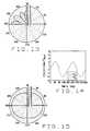
relates the magnetization angle α to the element position angle θ (implicitly through A and B). This is depicted as the solid line in FIG.3. From symmetry, the case bx=0 can be seen by extrapolation.
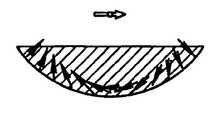
It also follows that for constant contributions of bx, the desired shape of the magnet is given by solving the x-component of equation (3) for r:
for which θ, again, is implicit in A and B. This is shown by the polar plot of
A few of the directions α (implicit in r(θ) are shown by the arrows around the r(θ) curve. The magnet shown in
and for ∂bx/∂y=0 it follows that
Likewise, a constant ∂bx/∂x for which ∂bx/∂y=0 yields
In these restricted cases, the correct 1/r4dependence of the gradient is retained so that the appropriate magnitudes are preserved. The multi-lobed shape curves (angular distribution curves) require more care in the use of symmetries, etc. in the design of the complete magnet, e.g. the choice of where to remove material.
C. Maximized Field Cases
The relationship between α and θ for this optimized field case is shown in dashed lines in FIG.6.
we calculate
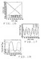
which yields the α-θ relationship shown in solid lines in FIG.16. The magnetic field component contribution is depicted in FIG.17 and the variable r takes the form of equation (12), but with the new implicit α-θ relationship changing the result. That is plotted in FIG.19.
which yields the α-θ relationship shown in dashed lines in FIG.16. Now
E. Maximized Field-Gradient Product Case
which represent the only unique components of the field-gradient product. All other cases for the field-gradient product follow from ∇·b=0 and ∇×b=0. From equations (3) and (4) we rewrite the field-gradient product in the form of
Thus for
we find that
and for
the relationship between α and θ becomes
where the condition for a maximum to exists for both equations (16) and (17) is that tan22α≧−1.
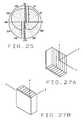
The relationship between α and θ, from equations (18) and (19), is shown in
These are shown as polar plots in
Operation
Claims (17)
Priority Applications (4)
| Application Number | Priority Date | Filing Date | Title |
|---|---|---|---|
| US10/082,715US6940379B2 (en) | 2000-04-11 | 2002-02-25 | Magnets with varying magnetization direction and method of making such magnets |
| US11/219,522US7286034B2 (en) | 2000-04-11 | 2005-09-02 | Magnets with varying magnetization direction and method of making such magnets |
| US11/877,661US20080092993A1 (en) | 2000-04-11 | 2007-10-23 | Magnets with Varying Magnetization Direction and Method of Making Such Magnets |
| US12/568,089US20100163061A1 (en) | 2000-04-11 | 2009-09-28 | Magnets with varying magnetization direction and method of making such magnets |
Applications Claiming Priority (2)
| Application Number | Priority Date | Filing Date | Title |
|---|---|---|---|
| US54684000A | 2000-04-11 | 2000-04-11 | |
| US10/082,715US6940379B2 (en) | 2000-04-11 | 2002-02-25 | Magnets with varying magnetization direction and method of making such magnets |
Related Parent Applications (1)
| Application Number | Title | Priority Date | Filing Date |
|---|---|---|---|
| US54684000AContinuation | 2000-04-11 | 2000-04-11 |
Related Child Applications (1)
| Application Number | Title | Priority Date | Filing Date |
|---|---|---|---|
| US11/219,522ContinuationUS7286034B2 (en) | 2000-04-11 | 2005-09-02 | Magnets with varying magnetization direction and method of making such magnets |
Publications (2)
| Publication Number | Publication Date |
|---|---|
| US20020113678A1 US20020113678A1 (en) | 2002-08-22 |
| US6940379B2true US6940379B2 (en) | 2005-09-06 |
Family
ID=24182248
Family Applications (4)
| Application Number | Title | Priority Date | Filing Date |
|---|---|---|---|
| US10/082,715Expired - LifetimeUS6940379B2 (en) | 2000-04-11 | 2002-02-25 | Magnets with varying magnetization direction and method of making such magnets |
| US11/219,522Expired - LifetimeUS7286034B2 (en) | 2000-04-11 | 2005-09-02 | Magnets with varying magnetization direction and method of making such magnets |
| US11/877,661AbandonedUS20080092993A1 (en) | 2000-04-11 | 2007-10-23 | Magnets with Varying Magnetization Direction and Method of Making Such Magnets |
| US12/568,089AbandonedUS20100163061A1 (en) | 2000-04-11 | 2009-09-28 | Magnets with varying magnetization direction and method of making such magnets |
Family Applications After (3)
| Application Number | Title | Priority Date | Filing Date |
|---|---|---|---|
| US11/219,522Expired - LifetimeUS7286034B2 (en) | 2000-04-11 | 2005-09-02 | Magnets with varying magnetization direction and method of making such magnets |
| US11/877,661AbandonedUS20080092993A1 (en) | 2000-04-11 | 2007-10-23 | Magnets with Varying Magnetization Direction and Method of Making Such Magnets |
| US12/568,089AbandonedUS20100163061A1 (en) | 2000-04-11 | 2009-09-28 | Magnets with varying magnetization direction and method of making such magnets |
Country Status (1)
| Country | Link |
|---|---|
| US (4) | US6940379B2 (en) |
Cited By (71)
| Publication number | Priority date | Publication date | Assignee | Title |
|---|---|---|---|---|
| US20060061445A1 (en)* | 2000-04-11 | 2006-03-23 | Stereotaxis, Inc. | Magnets with varying magnetization direction and method of making such magnets |
| US20070286308A1 (en)* | 2006-06-12 | 2007-12-13 | Thomas Holtzman Williams | System and method for modulated signal generation method using two equal, constant-amplitude, adjustable-phase carrier waves |
| US7537570B2 (en) | 2006-09-11 | 2009-05-26 | Stereotaxis, Inc. | Automated mapping of anatomical features of heart chambers |
| US7708696B2 (en) | 2005-01-11 | 2010-05-04 | Stereotaxis, Inc. | Navigation using sensed physiological data as feedback |
| US7757694B2 (en) | 1999-10-04 | 2010-07-20 | Stereotaxis, Inc. | Method for safely and efficiently navigating magnetic devices in the body |
| US7772950B2 (en) | 2005-08-10 | 2010-08-10 | Stereotaxis, Inc. | Method and apparatus for dynamic magnetic field control using multiple magnets |
| US7818076B2 (en) | 2005-07-26 | 2010-10-19 | Stereotaxis, Inc. | Method and apparatus for multi-system remote surgical navigation from a single control center |
| US7961924B2 (en) | 2006-08-21 | 2011-06-14 | Stereotaxis, Inc. | Method of three-dimensional device localization using single-plane imaging |
| US7961926B2 (en) | 2005-02-07 | 2011-06-14 | Stereotaxis, Inc. | Registration of three-dimensional image data to 2D-image-derived data |
| US7966059B2 (en) | 1999-10-04 | 2011-06-21 | Stereotaxis, Inc. | Rotating and pivoting magnet for magnetic navigation |
| US8024024B2 (en) | 2007-06-27 | 2011-09-20 | Stereotaxis, Inc. | Remote control of medical devices using real time location data |
| US8060184B2 (en) | 2002-06-28 | 2011-11-15 | Stereotaxis, Inc. | Method of navigating medical devices in the presence of radiopaque material |
| US8135185B2 (en) | 2006-10-20 | 2012-03-13 | Stereotaxis, Inc. | Location and display of occluded portions of vessels on 3-D angiographic images |
| US8196590B2 (en) | 2003-05-02 | 2012-06-12 | Stereotaxis, Inc. | Variable magnetic moment MR navigation |
| US8231618B2 (en) | 2007-11-05 | 2012-07-31 | Stereotaxis, Inc. | Magnetically guided energy delivery apparatus |
| US8273081B2 (en) | 2006-09-08 | 2012-09-25 | Stereotaxis, Inc. | Impedance-based cardiac therapy planning method with a remote surgical navigation system |
| US8308628B2 (en) | 2009-11-02 | 2012-11-13 | Pulse Therapeutics, Inc. | Magnetic-based systems for treating occluded vessels |
| US8369934B2 (en) | 2004-12-20 | 2013-02-05 | Stereotaxis, Inc. | Contact over-torque with three-dimensional anatomical data |
| US20130057374A1 (en)* | 2010-05-19 | 2013-03-07 | Nissan Motor Co., Ltd. | Permanent magnet disposed in rotating electrical machine and manufacturing method of the same |
| US8437833B2 (en) | 2008-10-07 | 2013-05-07 | Bard Access Systems, Inc. | Percutaneous magnetic gastrostomy |
| US8478382B2 (en) | 2008-02-11 | 2013-07-02 | C. R. Bard, Inc. | Systems and methods for positioning a catheter |
| US8512256B2 (en) | 2006-10-23 | 2013-08-20 | Bard Access Systems, Inc. | Method of locating the tip of a central venous catheter |
| US8774907B2 (en) | 2006-10-23 | 2014-07-08 | Bard Access Systems, Inc. | Method of locating the tip of a central venous catheter |
| US8781555B2 (en) | 2007-11-26 | 2014-07-15 | C. R. Bard, Inc. | System for placement of a catheter including a signal-generating stylet |
| US8784336B2 (en) | 2005-08-24 | 2014-07-22 | C. R. Bard, Inc. | Stylet apparatuses and methods of manufacture |
| US8801693B2 (en) | 2010-10-29 | 2014-08-12 | C. R. Bard, Inc. | Bioimpedance-assisted placement of a medical device |
| US8849382B2 (en) | 2007-11-26 | 2014-09-30 | C. R. Bard, Inc. | Apparatus and display methods relating to intravascular placement of a catheter |
| USD724745S1 (en) | 2011-08-09 | 2015-03-17 | C. R. Bard, Inc. | Cap for an ultrasound probe |
| US9111016B2 (en) | 2007-07-06 | 2015-08-18 | Stereotaxis, Inc. | Management of live remote medical display |
| US9125578B2 (en) | 2009-06-12 | 2015-09-08 | Bard Access Systems, Inc. | Apparatus and method for catheter navigation and tip location |
| US9211107B2 (en) | 2011-11-07 | 2015-12-15 | C. R. Bard, Inc. | Ruggedized ultrasound hydrogel insert |
| US9314222B2 (en) | 2005-07-07 | 2016-04-19 | Stereotaxis, Inc. | Operation of a remote medical navigation system using ultrasound image |
| USD754357S1 (en) | 2011-08-09 | 2016-04-19 | C. R. Bard, Inc. | Ultrasound probe head |
| US9339206B2 (en) | 2009-06-12 | 2016-05-17 | Bard Access Systems, Inc. | Adaptor for endovascular electrocardiography |
| US9445734B2 (en) | 2009-06-12 | 2016-09-20 | Bard Access Systems, Inc. | Devices and methods for endovascular electrography |
| US9456766B2 (en) | 2007-11-26 | 2016-10-04 | C. R. Bard, Inc. | Apparatus for use with needle insertion guidance system |
| US9492097B2 (en) | 2007-11-26 | 2016-11-15 | C. R. Bard, Inc. | Needle length determination and calibration for insertion guidance system |
| US9521961B2 (en) | 2007-11-26 | 2016-12-20 | C. R. Bard, Inc. | Systems and methods for guiding a medical instrument |
| US9532724B2 (en) | 2009-06-12 | 2017-01-03 | Bard Access Systems, Inc. | Apparatus and method for catheter navigation using endovascular energy mapping |
| US9554716B2 (en) | 2007-11-26 | 2017-01-31 | C. R. Bard, Inc. | Insertion guidance system for needles and medical components |
| US9636031B2 (en) | 2007-11-26 | 2017-05-02 | C.R. Bard, Inc. | Stylets for use with apparatus for intravascular placement of a catheter |
| US9649048B2 (en) | 2007-11-26 | 2017-05-16 | C. R. Bard, Inc. | Systems and methods for breaching a sterile field for intravascular placement of a catheter |
| US9681823B2 (en) | 2007-11-26 | 2017-06-20 | C. R. Bard, Inc. | Integrated system for intravascular placement of a catheter |
| US9839372B2 (en) | 2014-02-06 | 2017-12-12 | C. R. Bard, Inc. | Systems and methods for guidance and placement of an intravascular device |
| US9883878B2 (en) | 2012-05-15 | 2018-02-06 | Pulse Therapeutics, Inc. | Magnetic-based systems and methods for manipulation of magnetic particles |
| US9901714B2 (en) | 2008-08-22 | 2018-02-27 | C. R. Bard, Inc. | Catheter assembly including ECG sensor and magnetic assemblies |
| US10046139B2 (en) | 2010-08-20 | 2018-08-14 | C. R. Bard, Inc. | Reconfirmation of ECG-assisted catheter tip placement |
| US10109418B2 (en) | 2013-05-03 | 2018-10-23 | Battelle Memorial Institute | System and process for friction consolidation fabrication of permanent magnets and other extrusion and non-extrusion structures |
| US10189063B2 (en) | 2013-03-22 | 2019-01-29 | Battelle Memorial Institute | System and process for formation of extrusion products |
| US10349890B2 (en) | 2015-06-26 | 2019-07-16 | C. R. Bard, Inc. | Connector interface for ECG-based catheter positioning system |
| US10449330B2 (en) | 2007-11-26 | 2019-10-22 | C. R. Bard, Inc. | Magnetic element-equipped needle assemblies |
| US10524691B2 (en) | 2007-11-26 | 2020-01-07 | C. R. Bard, Inc. | Needle assembly including an aligned magnetic element |
| US10537713B2 (en) | 2009-05-25 | 2020-01-21 | Stereotaxis, Inc. | Remote manipulator device |
| US10639008B2 (en) | 2009-10-08 | 2020-05-05 | C. R. Bard, Inc. | Support and cover structures for an ultrasound probe head |
| US10695811B2 (en) | 2013-03-22 | 2020-06-30 | Battelle Memorial Institute | Functionally graded coatings and claddings |
| US10751509B2 (en) | 2007-11-26 | 2020-08-25 | C. R. Bard, Inc. | Iconic representations for guidance of an indwelling medical device |
| US10820885B2 (en) | 2012-06-15 | 2020-11-03 | C. R. Bard, Inc. | Apparatus and methods for detection of a removable cap on an ultrasound probe |
| US10973584B2 (en) | 2015-01-19 | 2021-04-13 | Bard Access Systems, Inc. | Device and method for vascular access |
| US10992079B2 (en) | 2018-10-16 | 2021-04-27 | Bard Access Systems, Inc. | Safety-equipped connection systems and methods thereof for establishing electrical connections |
| US11000207B2 (en) | 2016-01-29 | 2021-05-11 | C. R. Bard, Inc. | Multiple coil system for tracking a medical device |
| US11045851B2 (en) | 2013-03-22 | 2021-06-29 | Battelle Memorial Institute | Method for Forming Hollow Profile Non-Circular Extrusions Using Shear Assisted Processing and Extrusion (ShAPE) |
| US11103213B2 (en) | 2009-10-08 | 2021-08-31 | C. R. Bard, Inc. | Spacers for use with an ultrasound probe |
| US11383280B2 (en) | 2013-03-22 | 2022-07-12 | Battelle Memorial Institute | Devices and methods for performing shear-assisted extrusion, extrusion feedstocks, extrusion processes, and methods for preparing metal sheets |
| US11549532B1 (en) | 2019-09-06 | 2023-01-10 | Battelle Memorial Institute | Assemblies, riveted assemblies, methods for affixing substrates, and methods for mixing materials to form a metallurgical bond |
| US11919061B2 (en) | 2021-09-15 | 2024-03-05 | Battelle Memorial Institute | Shear-assisted extrusion assemblies and methods |
| US11918315B2 (en) | 2018-05-03 | 2024-03-05 | Pulse Therapeutics, Inc. | Determination of structure and traversal of occlusions using magnetic particles |
| US12171443B1 (en) | 2021-03-09 | 2024-12-24 | Pulse Therapeutics, Inc. | Magnetically controlled flow generation |
| US12186791B2 (en) | 2013-03-22 | 2025-01-07 | Battelle Memorial Institute | Devices and methods for performing shear-assisted extrusion and extrusion processes |
| US12358035B2 (en) | 2013-03-22 | 2025-07-15 | Battelle Memorial Institute | Devices and methods for performing shear-assisted extrusion and extrusion processes |
| US12365027B2 (en) | 2013-03-22 | 2025-07-22 | Battelle Memorial Institute | High speed shear-assisted extrusion |
| US12403516B2 (en) | 2013-03-22 | 2025-09-02 | Battelle Memorial Institute | Shape processes, feedstock materials, conductive materials and/or assemblies |
Families Citing this family (57)
| Publication number | Priority date | Publication date | Assignee | Title |
|---|---|---|---|---|
| US20040030244A1 (en)* | 1999-08-06 | 2004-02-12 | Garibaldi Jeffrey M. | Method and apparatus for magnetically controlling catheters in body lumens and cavities |
| US6856006B2 (en)* | 2002-03-28 | 2005-02-15 | Siliconix Taiwan Ltd | Encapsulation method and leadframe for leadless semiconductor packages |
| GB0019506D0 (en)* | 2000-08-08 | 2000-09-27 | Univ Cambridge Tech | Magnetic element with switchable domain structure |
| US7161453B2 (en)* | 2002-01-23 | 2007-01-09 | Stereotaxis, Inc. | Rotating and pivoting magnet for magnetic navigation |
| WO2005029258A2 (en)* | 2003-09-16 | 2005-03-31 | Stereotaxis, Inc. | User interface for remote control of medical devices |
| US20070060992A1 (en)* | 2005-06-02 | 2007-03-15 | Carlo Pappone | Methods and devices for mapping the ventricle for pacing lead placement and therapy delivery |
| US7769444B2 (en)* | 2005-07-11 | 2010-08-03 | Stereotaxis, Inc. | Method of treating cardiac arrhythmias |
| US20070016131A1 (en)* | 2005-07-12 | 2007-01-18 | Munger Gareth T | Flexible magnets for navigable medical devices |
| US20070060829A1 (en)* | 2005-07-21 | 2007-03-15 | Carlo Pappone | Method of finding the source of and treating cardiac arrhythmias |
| US20070062547A1 (en)* | 2005-07-21 | 2007-03-22 | Carlo Pappone | Systems for and methods of tissue ablation |
| US20070060962A1 (en)* | 2005-07-26 | 2007-03-15 | Carlo Pappone | Apparatus and methods for cardiac resynchronization therapy and cardiac contractility modulation |
| US20070167720A1 (en)* | 2005-12-06 | 2007-07-19 | Viswanathan Raju R | Smart card control of medical devices |
| US20070149946A1 (en)* | 2005-12-07 | 2007-06-28 | Viswanathan Raju R | Advancer system for coaxial medical devices |
| US20070161882A1 (en)* | 2006-01-06 | 2007-07-12 | Carlo Pappone | Electrophysiology catheter and system for gentle and firm wall contact |
| US20070197899A1 (en)* | 2006-01-17 | 2007-08-23 | Ritter Rogers C | Apparatus and method for magnetic navigation using boost magnets |
| US20080015670A1 (en)* | 2006-01-17 | 2008-01-17 | Carlo Pappone | Methods and devices for cardiac ablation |
| US20070197906A1 (en)* | 2006-01-24 | 2007-08-23 | Ritter Rogers C | Magnetic field shape-adjustable medical device and method of using the same |
| US20070250041A1 (en)* | 2006-04-19 | 2007-10-25 | Werp Peter R | Extendable Interventional Medical Devices |
| DE102006034471B4 (en)* | 2006-07-26 | 2010-08-19 | Forschungszentrum Jülich GmbH | Device for generating a graded homogeneous magnetic field |
| WO2008022148A2 (en)* | 2006-08-14 | 2008-02-21 | Stereotaxis, Inc. | Method and apparatus for ablative recanalization of blocked vasculature |
| US20080114335A1 (en)* | 2006-08-23 | 2008-05-15 | William Flickinger | Medical Device Guide |
| US8242972B2 (en) | 2006-09-06 | 2012-08-14 | Stereotaxis, Inc. | System state driven display for medical procedures |
| US7567233B2 (en)* | 2006-09-06 | 2009-07-28 | Stereotaxis, Inc. | Global input device for multiple computer-controlled medical systems |
| US8244824B2 (en)* | 2006-09-06 | 2012-08-14 | Stereotaxis, Inc. | Coordinated control for multiple computer-controlled medical systems |
| US7747960B2 (en) | 2006-09-06 | 2010-06-29 | Stereotaxis, Inc. | Control for, and method of, operating at least two medical systems |
| WO2008057565A2 (en)* | 2006-11-06 | 2008-05-15 | Howmedica Osteonics Corp. | Artificial cushion joints and methods of making the same |
| US20080132910A1 (en)* | 2006-11-07 | 2008-06-05 | Carlo Pappone | Control for a Remote Navigation System |
| US20080200913A1 (en)* | 2007-02-07 | 2008-08-21 | Viswanathan Raju R | Single Catheter Navigation for Diagnosis and Treatment of Arrhythmias |
| US20080208912A1 (en)* | 2007-02-26 | 2008-08-28 | Garibaldi Jeffrey M | System and method for providing contextually relevant medical information |
| US20080228065A1 (en)* | 2007-03-13 | 2008-09-18 | Viswanathan Raju R | System and Method for Registration of Localization and Imaging Systems for Navigational Control of Medical Devices |
| US20080228068A1 (en)* | 2007-03-13 | 2008-09-18 | Viswanathan Raju R | Automated Surgical Navigation with Electro-Anatomical and Pre-Operative Image Data |
| US20080287909A1 (en)* | 2007-05-17 | 2008-11-20 | Viswanathan Raju R | Method and apparatus for intra-chamber needle injection treatment |
| US20080294232A1 (en)* | 2007-05-22 | 2008-11-27 | Viswanathan Raju R | Magnetic cell delivery |
| CN101311284A (en)* | 2007-05-24 | 2008-11-26 | 鸿富锦精密工业(深圳)有限公司 | Magnesium alloy and magnesium alloy thin material |
| US20090082722A1 (en)* | 2007-08-21 | 2009-03-26 | Munger Gareth T | Remote navigation advancer devices and methods of use |
| US20090105579A1 (en)* | 2007-10-19 | 2009-04-23 | Garibaldi Jeffrey M | Method and apparatus for remotely controlled navigation using diagnostically enhanced intra-operative three-dimensional image data |
| US20090131798A1 (en)* | 2007-11-19 | 2009-05-21 | Minar Christopher D | Method and apparatus for intravascular imaging and occlusion crossing |
| US20090131927A1 (en)* | 2007-11-20 | 2009-05-21 | Nathan Kastelein | Method and apparatus for remote detection of rf ablation |
| FR2937722B1 (en)* | 2008-10-24 | 2010-11-26 | Moving Magnet Tech Mmt | MAGNETIC POSITION SENSOR WITH FIELD DIRECTION MEASUREMENT AND FLOW COLLECTOR |
| US20110046618A1 (en)* | 2009-08-04 | 2011-02-24 | Minar Christopher D | Methods and systems for treating occluded blood vessels and other body cannula |
| CN102822630B (en)* | 2010-02-12 | 2015-10-21 | 马夸特机械电子有限责任公司 | method for position measurement |
| EP4032486A1 (en) | 2010-11-16 | 2022-07-27 | TVA Medical, Inc. | Devices for forming a fistula |
| US9651353B2 (en)* | 2012-07-24 | 2017-05-16 | International Business Machines Corporation | Calibration free distance sensor |
| CN104953780A (en) | 2012-08-03 | 2015-09-30 | 埃塞克科技有限公司 | Modular rotatable transverse flux electrical machine |
| US9559558B2 (en) | 2012-09-24 | 2017-01-31 | Eocycle Technologies Inc. | Modular transverse flux electrical machine assembly |
| US9486276B2 (en) | 2012-10-11 | 2016-11-08 | Tva Medical, Inc. | Devices and methods for fistula formation |
| CA2829812A1 (en) | 2012-10-17 | 2014-04-17 | Eocycle Technologies Inc. | Transverse flux electrical machine rotor |
| CN105228683B (en) | 2013-03-14 | 2022-06-10 | Tva医疗公司 | Fistula-forming device and method for forming fistula |
| US10695534B2 (en) | 2014-03-14 | 2020-06-30 | Tva Medical, Inc. | Fistula formation devices and methods therefor |
| WO2016033374A1 (en) | 2014-08-27 | 2016-03-03 | Tva Medical, Inc. | Cryolipopysis devices and methods therefor |
| US10603040B1 (en) | 2015-02-09 | 2020-03-31 | Tva Medical, Inc. | Methods for treating hypertension and reducing blood pressure with formation of fistula |
| CN114042224B (en) | 2016-01-15 | 2024-09-17 | Tva医疗公司 | Device and method for advancing a wire |
| WO2017124062A1 (en) | 2016-01-15 | 2017-07-20 | Tva Medical, Inc. | Devices and methods for forming a fistula |
| JP7219090B2 (en) | 2016-01-15 | 2023-02-07 | ティーブイエー メディカル, インコーポレイテッド | Systems and methods for gluing vessels |
| US10874422B2 (en) | 2016-01-15 | 2020-12-29 | Tva Medical, Inc. | Systems and methods for increasing blood flow |
| CN109982652B (en) | 2016-09-25 | 2022-08-05 | Tva医疗公司 | Vascular stent device and method |
| US11398330B2 (en)* | 2018-10-19 | 2022-07-26 | Magmedics, LLC | Therapeutic field directional magnetic array |
Citations (7)
| Publication number | Priority date | Publication date | Assignee | Title |
|---|---|---|---|---|
| US5216400A (en)* | 1992-06-02 | 1993-06-01 | The United States Of America As Represented By The Secretary Of The Army | Magnetic field sources for producing high-intensity variable fields |
| US5257636A (en) | 1991-04-02 | 1993-11-02 | Steven J. White | Apparatus for determining position of an endothracheal tube |
| US5312321A (en) | 1986-11-21 | 1994-05-17 | Holcomb Technology, Inc. | Method and apparatus for suppressing neuron action potential firings |
| US5523732A (en)* | 1995-10-16 | 1996-06-04 | The United States Of America As Represented By The Secretary Of The Army | Multi-mode adjustable magic ring |
| US5622169A (en) | 1993-09-14 | 1997-04-22 | University Of Washington | Apparatus and method for locating a medical tube in the body of a patient |
| US5681260A (en) | 1989-09-22 | 1997-10-28 | Olympus Optical Co., Ltd. | Guiding apparatus for guiding an insertable body within an inspected object |
| US5711299A (en)* | 1996-01-26 | 1998-01-27 | Manwaring; Kim H. | Surgical guidance method and system for approaching a target within a body |
Family Cites Families (89)
| Publication number | Priority date | Publication date | Assignee | Title |
|---|---|---|---|---|
| US4829277A (en)* | 1986-11-20 | 1989-05-09 | General Motors Corporation | Isotropic rare earth-iron field magnets for magnetic resonance imaging |
| US5312621A (en)* | 1988-01-25 | 1994-05-17 | Baker Cummins Dermatologicals, Inc. | Method of treating fibrotic disorders |
| DE4039320A1 (en)* | 1990-12-10 | 1992-06-11 | Kloeckner Humboldt Deutz Ag | Magnet system for magnetic separator - comprises ring of magnetic blocks with varying magnetisation directions |
| JPH067316A (en)* | 1992-06-29 | 1994-01-18 | Hitachi Medical Corp | Magnetic field generating device of magnetic resonance imaging system |
| US5634263A (en)* | 1995-09-11 | 1997-06-03 | The United States Of America As Represented By The Secretary Of The Army | Methods of manufacture of permanent magnet structures with sheet material |
| US5719469A (en)* | 1995-12-28 | 1998-02-17 | The United States Of America As Represented By The Secretary Of The Army | Spherical magnet having a gap with a periodically varying field for a wiggler radiation source |
| US6015414A (en)* | 1997-08-29 | 2000-01-18 | Stereotaxis, Inc. | Method and apparatus for magnetically controlling motion direction of a mechanically pushed catheter |
| US5886609A (en)* | 1997-10-22 | 1999-03-23 | Dexter Magnetic Technologies, Inc. | Single dipole permanent magnet structure with linear gradient magnetic field intensity |
| US6014580A (en)* | 1997-11-12 | 2000-01-11 | Stereotaxis, Inc. | Device and method for specifying magnetic field for surgical applications |
| US6212419B1 (en)* | 1997-11-12 | 2001-04-03 | Walter M. Blume | Method and apparatus using shaped field of repositionable magnet to guide implant |
| US7066924B1 (en)* | 1997-11-12 | 2006-06-27 | Stereotaxis, Inc. | Method of and apparatus for navigating medical devices in body lumens by a guide wire with a magnetic tip |
| US6505062B1 (en)* | 1998-02-09 | 2003-01-07 | Stereotaxis, Inc. | Method for locating magnetic implant by source field |
| US20040030244A1 (en)* | 1999-08-06 | 2004-02-12 | Garibaldi Jeffrey M. | Method and apparatus for magnetically controlling catheters in body lumens and cavities |
| EP1115327A4 (en)* | 1998-08-07 | 2007-06-20 | Stereotaxis Inc | Method and apparatus for magnetically controlling catheters in body lumens and cavities |
| US6385472B1 (en)* | 1999-09-10 | 2002-05-07 | Stereotaxis, Inc. | Magnetically navigable telescoping catheter and method of navigating telescoping catheter |
| AU6279299A (en)* | 1998-10-02 | 2000-04-26 | Stereotaxis, Inc. | Magnetically navigable and/or controllable device for removing material from body lumens and cavities |
| US6330467B1 (en)* | 1999-02-04 | 2001-12-11 | Stereotaxis, Inc. | Efficient magnet system for magnetically-assisted surgery |
| US6375606B1 (en)* | 1999-03-17 | 2002-04-23 | Stereotaxis, Inc. | Methods of and apparatus for treating vascular defects |
| US6296604B1 (en)* | 1999-03-17 | 2001-10-02 | Stereotaxis, Inc. | Methods of and compositions for treating vascular defects |
| US6911026B1 (en)* | 1999-07-12 | 2005-06-28 | Stereotaxis, Inc. | Magnetically guided atherectomy |
| US6902528B1 (en)* | 1999-04-14 | 2005-06-07 | Stereotaxis, Inc. | Method and apparatus for magnetically controlling endoscopes in body lumens and cavities |
| US6292678B1 (en)* | 1999-05-13 | 2001-09-18 | Stereotaxis, Inc. | Method of magnetically navigating medical devices with magnetic fields and gradients, and medical devices adapted therefor |
| AU3885801A (en)* | 1999-09-20 | 2001-04-24 | Stereotaxis, Inc. | Magnetically guided myocardial treatment system |
| US7019610B2 (en)* | 2002-01-23 | 2006-03-28 | Stereotaxis, Inc. | Magnetic navigation system |
| US6702804B1 (en)* | 1999-10-04 | 2004-03-09 | Stereotaxis, Inc. | Method for safely and efficiently navigating magnetic devices in the body |
| US6401723B1 (en)* | 2000-02-16 | 2002-06-11 | Stereotaxis, Inc. | Magnetic medical devices with changeable magnetic moments and method of navigating magnetic medical devices with changeable magnetic moments |
| US6680663B1 (en)* | 2000-03-24 | 2004-01-20 | Iowa State University Research Foundation, Inc. | Permanent magnet structure for generation of magnetic fields |
| US6940379B2 (en)* | 2000-04-11 | 2005-09-06 | Stereotaxis, Inc. | Magnets with varying magnetization direction and method of making such magnets |
| AU2001275511A1 (en)* | 2000-06-07 | 2001-12-17 | Stereotaxis, Inc. | Guide for medical devices |
| US6524303B1 (en)* | 2000-09-08 | 2003-02-25 | Stereotaxis, Inc. | Variable stiffness magnetic catheter |
| US6537196B1 (en)* | 2000-10-24 | 2003-03-25 | Stereotaxis, Inc. | Magnet assembly with variable field directions and methods of magnetically navigating medical objects |
| US6677752B1 (en)* | 2000-11-20 | 2004-01-13 | Stereotaxis, Inc. | Close-in shielding system for magnetic medical treatment instruments |
| US6352363B1 (en)* | 2001-01-16 | 2002-03-05 | Stereotaxis, Inc. | Shielded x-ray source, method of shielding an x-ray source, and magnetic surgical system with shielded x-ray source |
| JP4623848B2 (en)* | 2001-03-23 | 2011-02-02 | 日立金属株式会社 | Magnetic field generator |
| US7766856B2 (en)* | 2001-05-06 | 2010-08-03 | Stereotaxis, Inc. | System and methods for advancing a catheter |
| US6396378B1 (en)* | 2001-09-17 | 2002-05-28 | The United States Of America As Represented By The Secretary Of The Army | Fine taper adjustment in a magic cylinder |
| US7020512B2 (en)* | 2002-01-14 | 2006-03-28 | Stereotaxis, Inc. | Method of localizing medical devices |
| US7161453B2 (en)* | 2002-01-23 | 2007-01-09 | Stereotaxis, Inc. | Rotating and pivoting magnet for magnetic navigation |
| US8721655B2 (en)* | 2002-04-10 | 2014-05-13 | Stereotaxis, Inc. | Efficient closed loop feedback navigation |
| US7008418B2 (en)* | 2002-05-09 | 2006-03-07 | Stereotaxis, Inc. | Magnetically assisted pulmonary vein isolation |
| US7248914B2 (en)* | 2002-06-28 | 2007-07-24 | Stereotaxis, Inc. | Method of navigating medical devices in the presence of radiopaque material |
| US7189198B2 (en)* | 2002-07-03 | 2007-03-13 | Stereotaxis, Inc. | Magnetically guidable carriers and methods for the targeted magnetic delivery of substances in the body |
| US7769427B2 (en)* | 2002-07-16 | 2010-08-03 | Magnetics, Inc. | Apparatus and method for catheter guidance control and imaging |
| US20080016678A1 (en)* | 2002-11-07 | 2008-01-24 | Creighton Iv Francis M | Method of making a compound magnet |
| US6980843B2 (en)* | 2003-05-21 | 2005-12-27 | Stereotaxis, Inc. | Electrophysiology catheter |
| US20050065435A1 (en)* | 2003-07-22 | 2005-03-24 | John Rauch | User interface for remote control of medical devices |
| US20060025679A1 (en)* | 2004-06-04 | 2006-02-02 | Viswanathan Raju R | User interface for remote control of medical devices |
| US7769428B2 (en)* | 2004-06-29 | 2010-08-03 | Stereotaxis, Inc. | Navigation of remotely actuable medical device using control variable and length |
| US20060036163A1 (en)* | 2004-07-19 | 2006-02-16 | Viswanathan Raju R | Method of, and apparatus for, controlling medical navigation systems |
| US20080006280A1 (en)* | 2004-07-20 | 2008-01-10 | Anthony Aliberto | Magnetic navigation maneuvering sheath |
| US6861935B1 (en)* | 2004-08-04 | 2005-03-01 | The United States Of America As Represented By The Secretary Of The Army | Field tapering in magnetic spheres and cylinders with distortion free access |
| KR100662564B1 (en)* | 2004-08-19 | 2006-12-28 | 삼성전자주식회사 | Alignment device |
| US7815580B2 (en)* | 2004-09-07 | 2010-10-19 | Stereotaxis, Inc. | Magnetic guidewire for lesion crossing |
| US7831294B2 (en)* | 2004-10-07 | 2010-11-09 | Stereotaxis, Inc. | System and method of surgical imagining with anatomical overlay for navigation of surgical devices |
| US7190819B2 (en)* | 2004-10-29 | 2007-03-13 | Stereotaxis, Inc. | Image-based medical device localization |
| US20070032746A1 (en)* | 2005-01-10 | 2007-02-08 | Stereotaxis, Inc. | Guide wire with magnetically adjustable bent tip and method for using the same |
| US7657075B2 (en)* | 2005-05-06 | 2010-02-02 | Stereotaxis, Inc. | Registration of three dimensional image data with X-ray imaging system |
| WO2006121972A2 (en)* | 2005-05-06 | 2006-11-16 | Stereoraxis, Inc. | Preoperative and intra-operative imaging-based procedure workflow with complexity scoring |
| US20070060992A1 (en)* | 2005-06-02 | 2007-03-15 | Carlo Pappone | Methods and devices for mapping the ventricle for pacing lead placement and therapy delivery |
| US20070062546A1 (en)* | 2005-06-02 | 2007-03-22 | Viswanathan Raju R | Electrophysiology catheter and system for gentle and firm wall contact |
| US9314222B2 (en)* | 2005-07-07 | 2016-04-19 | Stereotaxis, Inc. | Operation of a remote medical navigation system using ultrasound image |
| US20070021744A1 (en)* | 2005-07-07 | 2007-01-25 | Creighton Francis M Iv | Apparatus and method for performing ablation with imaging feedback |
| US20070038065A1 (en)* | 2005-07-07 | 2007-02-15 | Creighton Francis M Iv | Operation of a remote medical navigation system using ultrasound image |
| US7769444B2 (en)* | 2005-07-11 | 2010-08-03 | Stereotaxis, Inc. | Method of treating cardiac arrhythmias |
| US20070016131A1 (en)* | 2005-07-12 | 2007-01-18 | Munger Gareth T | Flexible magnets for navigable medical devices |
| US7690619B2 (en)* | 2005-07-12 | 2010-04-06 | Stereotaxis, Inc. | Apparatus for pivotally orienting a projection device |
| US8192374B2 (en)* | 2005-07-18 | 2012-06-05 | Stereotaxis, Inc. | Estimation of contact force by a medical device |
| US20070062547A1 (en)* | 2005-07-21 | 2007-03-22 | Carlo Pappone | Systems for and methods of tissue ablation |
| US20070060829A1 (en)* | 2005-07-21 | 2007-03-15 | Carlo Pappone | Method of finding the source of and treating cardiac arrhythmias |
| US20070040670A1 (en)* | 2005-07-26 | 2007-02-22 | Viswanathan Raju R | System and network for remote medical procedures |
| US20070060916A1 (en)* | 2005-07-26 | 2007-03-15 | Carlo Pappone | System and network for remote medical procedures |
| US20070060962A1 (en)* | 2005-07-26 | 2007-03-15 | Carlo Pappone | Apparatus and methods for cardiac resynchronization therapy and cardiac contractility modulation |
| US20070043455A1 (en)* | 2005-07-26 | 2007-02-22 | Viswanathan Raju R | Apparatus and methods for automated sequential movement control for operation of a remote navigation system |
| US7495537B2 (en)* | 2005-08-10 | 2009-02-24 | Stereotaxis, Inc. | Method and apparatus for dynamic magnetic field control using multiple magnets |
| US20070049909A1 (en)* | 2005-08-26 | 2007-03-01 | Munger Gareth T | Magnetically enabled optical ablation device |
| US20070055124A1 (en)* | 2005-09-01 | 2007-03-08 | Viswanathan Raju R | Method and system for optimizing left-heart lead placement |
| US7662126B2 (en)* | 2005-09-02 | 2010-02-16 | Stereotaxis, Inc. | Ultrasonic disbursement of magnetically delivered substances |
| US20080015670A1 (en)* | 2006-01-17 | 2008-01-17 | Carlo Pappone | Methods and devices for cardiac ablation |
| US20080039705A1 (en)* | 2006-05-03 | 2008-02-14 | Viswanathan Raju R | Map based intuitive device control and sensing to navigate a medical device |
| WO2008003059A2 (en)* | 2006-06-28 | 2008-01-03 | Stereotaxis, Inc. | Electrostriction devices and methods for assisted magnetic navigation |
| US20080015427A1 (en)* | 2006-06-30 | 2008-01-17 | Nathan Kastelein | System and network for remote medical procedures |
| WO2008022148A2 (en)* | 2006-08-14 | 2008-02-21 | Stereotaxis, Inc. | Method and apparatus for ablative recanalization of blocked vasculature |
| US7961924B2 (en)* | 2006-08-21 | 2011-06-14 | Stereotaxis, Inc. | Method of three-dimensional device localization using single-plane imaging |
| US8242972B2 (en)* | 2006-09-06 | 2012-08-14 | Stereotaxis, Inc. | System state driven display for medical procedures |
| US7747960B2 (en)* | 2006-09-06 | 2010-06-29 | Stereotaxis, Inc. | Control for, and method of, operating at least two medical systems |
| US8244824B2 (en)* | 2006-09-06 | 2012-08-14 | Stereotaxis, Inc. | Coordinated control for multiple computer-controlled medical systems |
| US8273081B2 (en)* | 2006-09-08 | 2012-09-25 | Stereotaxis, Inc. | Impedance-based cardiac therapy planning method with a remote surgical navigation system |
| WO2009009497A1 (en)* | 2007-07-06 | 2009-01-15 | Stereotaxis, Inc. | Management of live remote medical display |
| US20090082722A1 (en)* | 2007-08-21 | 2009-03-26 | Munger Gareth T | Remote navigation advancer devices and methods of use |
- 2002
- 2002-02-25USUS10/082,715patent/US6940379B2/ennot_activeExpired - Lifetime
- 2005
- 2005-09-02USUS11/219,522patent/US7286034B2/ennot_activeExpired - Lifetime
- 2007
- 2007-10-23USUS11/877,661patent/US20080092993A1/ennot_activeAbandoned
- 2009
- 2009-09-28USUS12/568,089patent/US20100163061A1/ennot_activeAbandoned
Patent Citations (7)
| Publication number | Priority date | Publication date | Assignee | Title |
|---|---|---|---|---|
| US5312321A (en) | 1986-11-21 | 1994-05-17 | Holcomb Technology, Inc. | Method and apparatus for suppressing neuron action potential firings |
| US5681260A (en) | 1989-09-22 | 1997-10-28 | Olympus Optical Co., Ltd. | Guiding apparatus for guiding an insertable body within an inspected object |
| US5257636A (en) | 1991-04-02 | 1993-11-02 | Steven J. White | Apparatus for determining position of an endothracheal tube |
| US5216400A (en)* | 1992-06-02 | 1993-06-01 | The United States Of America As Represented By The Secretary Of The Army | Magnetic field sources for producing high-intensity variable fields |
| US5622169A (en) | 1993-09-14 | 1997-04-22 | University Of Washington | Apparatus and method for locating a medical tube in the body of a patient |
| US5523732A (en)* | 1995-10-16 | 1996-06-04 | The United States Of America As Represented By The Secretary Of The Army | Multi-mode adjustable magic ring |
| US5711299A (en)* | 1996-01-26 | 1998-01-27 | Manwaring; Kim H. | Surgical guidance method and system for approaching a target within a body |
Cited By (128)
| Publication number | Priority date | Publication date | Assignee | Title |
|---|---|---|---|---|
| US7757694B2 (en) | 1999-10-04 | 2010-07-20 | Stereotaxis, Inc. | Method for safely and efficiently navigating magnetic devices in the body |
| US7966059B2 (en) | 1999-10-04 | 2011-06-21 | Stereotaxis, Inc. | Rotating and pivoting magnet for magnetic navigation |
| US7286034B2 (en) | 2000-04-11 | 2007-10-23 | Stereotaxis, Inc. | Magnets with varying magnetization direction and method of making such magnets |
| US20080092993A1 (en)* | 2000-04-11 | 2008-04-24 | Creighton Francis M | Magnets with Varying Magnetization Direction and Method of Making Such Magnets |
| US20060061445A1 (en)* | 2000-04-11 | 2006-03-23 | Stereotaxis, Inc. | Magnets with varying magnetization direction and method of making such magnets |
| US8060184B2 (en) | 2002-06-28 | 2011-11-15 | Stereotaxis, Inc. | Method of navigating medical devices in the presence of radiopaque material |
| US8196590B2 (en) | 2003-05-02 | 2012-06-12 | Stereotaxis, Inc. | Variable magnetic moment MR navigation |
| US8369934B2 (en) | 2004-12-20 | 2013-02-05 | Stereotaxis, Inc. | Contact over-torque with three-dimensional anatomical data |
| US7708696B2 (en) | 2005-01-11 | 2010-05-04 | Stereotaxis, Inc. | Navigation using sensed physiological data as feedback |
| US7961926B2 (en) | 2005-02-07 | 2011-06-14 | Stereotaxis, Inc. | Registration of three-dimensional image data to 2D-image-derived data |
| US9314222B2 (en) | 2005-07-07 | 2016-04-19 | Stereotaxis, Inc. | Operation of a remote medical navigation system using ultrasound image |
| US7818076B2 (en) | 2005-07-26 | 2010-10-19 | Stereotaxis, Inc. | Method and apparatus for multi-system remote surgical navigation from a single control center |
| US7772950B2 (en) | 2005-08-10 | 2010-08-10 | Stereotaxis, Inc. | Method and apparatus for dynamic magnetic field control using multiple magnets |
| US11207496B2 (en) | 2005-08-24 | 2021-12-28 | C. R. Bard, Inc. | Stylet apparatuses and methods of manufacture |
| US8784336B2 (en) | 2005-08-24 | 2014-07-22 | C. R. Bard, Inc. | Stylet apparatuses and methods of manufacture |
| US10004875B2 (en) | 2005-08-24 | 2018-06-26 | C. R. Bard, Inc. | Stylet apparatuses and methods of manufacture |
| US20070286308A1 (en)* | 2006-06-12 | 2007-12-13 | Thomas Holtzman Williams | System and method for modulated signal generation method using two equal, constant-amplitude, adjustable-phase carrier waves |
| US7961924B2 (en) | 2006-08-21 | 2011-06-14 | Stereotaxis, Inc. | Method of three-dimensional device localization using single-plane imaging |
| US8273081B2 (en) | 2006-09-08 | 2012-09-25 | Stereotaxis, Inc. | Impedance-based cardiac therapy planning method with a remote surgical navigation system |
| US7537570B2 (en) | 2006-09-11 | 2009-05-26 | Stereotaxis, Inc. | Automated mapping of anatomical features of heart chambers |
| US8135185B2 (en) | 2006-10-20 | 2012-03-13 | Stereotaxis, Inc. | Location and display of occluded portions of vessels on 3-D angiographic images |
| US8858455B2 (en) | 2006-10-23 | 2014-10-14 | Bard Access Systems, Inc. | Method of locating the tip of a central venous catheter |
| US9833169B2 (en) | 2006-10-23 | 2017-12-05 | Bard Access Systems, Inc. | Method of locating the tip of a central venous catheter |
| US9345422B2 (en) | 2006-10-23 | 2016-05-24 | Bard Acess Systems, Inc. | Method of locating the tip of a central venous catheter |
| US8512256B2 (en) | 2006-10-23 | 2013-08-20 | Bard Access Systems, Inc. | Method of locating the tip of a central venous catheter |
| US9265443B2 (en) | 2006-10-23 | 2016-02-23 | Bard Access Systems, Inc. | Method of locating the tip of a central venous catheter |
| US8774907B2 (en) | 2006-10-23 | 2014-07-08 | Bard Access Systems, Inc. | Method of locating the tip of a central venous catheter |
| US8024024B2 (en) | 2007-06-27 | 2011-09-20 | Stereotaxis, Inc. | Remote control of medical devices using real time location data |
| US9111016B2 (en) | 2007-07-06 | 2015-08-18 | Stereotaxis, Inc. | Management of live remote medical display |
| US8231618B2 (en) | 2007-11-05 | 2012-07-31 | Stereotaxis, Inc. | Magnetically guided energy delivery apparatus |
| US9999371B2 (en) | 2007-11-26 | 2018-06-19 | C. R. Bard, Inc. | Integrated system for intravascular placement of a catheter |
| US10524691B2 (en) | 2007-11-26 | 2020-01-07 | C. R. Bard, Inc. | Needle assembly including an aligned magnetic element |
| US8849382B2 (en) | 2007-11-26 | 2014-09-30 | C. R. Bard, Inc. | Apparatus and display methods relating to intravascular placement of a catheter |
| US11779240B2 (en) | 2007-11-26 | 2023-10-10 | C. R. Bard, Inc. | Systems and methods for breaching a sterile field for intravascular placement of a catheter |
| US11707205B2 (en) | 2007-11-26 | 2023-07-25 | C. R. Bard, Inc. | Integrated system for intravascular placement of a catheter |
| US11529070B2 (en) | 2007-11-26 | 2022-12-20 | C. R. Bard, Inc. | System and methods for guiding a medical instrument |
| US11134915B2 (en) | 2007-11-26 | 2021-10-05 | C. R. Bard, Inc. | System for placement of a catheter including a signal-generating stylet |
| US8781555B2 (en) | 2007-11-26 | 2014-07-15 | C. R. Bard, Inc. | System for placement of a catheter including a signal-generating stylet |
| US11123099B2 (en) | 2007-11-26 | 2021-09-21 | C. R. Bard, Inc. | Apparatus for use with needle insertion guidance system |
| US10966630B2 (en) | 2007-11-26 | 2021-04-06 | C. R. Bard, Inc. | Integrated system for intravascular placement of a catheter |
| US10849695B2 (en) | 2007-11-26 | 2020-12-01 | C. R. Bard, Inc. | Systems and methods for breaching a sterile field for intravascular placement of a catheter |
| US10751509B2 (en) | 2007-11-26 | 2020-08-25 | C. R. Bard, Inc. | Iconic representations for guidance of an indwelling medical device |
| US10602958B2 (en) | 2007-11-26 | 2020-03-31 | C. R. Bard, Inc. | Systems and methods for guiding a medical instrument |
| US10449330B2 (en) | 2007-11-26 | 2019-10-22 | C. R. Bard, Inc. | Magnetic element-equipped needle assemblies |
| US10342575B2 (en) | 2007-11-26 | 2019-07-09 | C. R. Bard, Inc. | Apparatus for use with needle insertion guidance system |
| US10238418B2 (en) | 2007-11-26 | 2019-03-26 | C. R. Bard, Inc. | Apparatus for use with needle insertion guidance system |
| US10231753B2 (en) | 2007-11-26 | 2019-03-19 | C. R. Bard, Inc. | Insertion guidance system for needles and medical components |
| US10165962B2 (en) | 2007-11-26 | 2019-01-01 | C. R. Bard, Inc. | Integrated systems for intravascular placement of a catheter |
| US10105121B2 (en) | 2007-11-26 | 2018-10-23 | C. R. Bard, Inc. | System for placement of a catheter including a signal-generating stylet |
| US9456766B2 (en) | 2007-11-26 | 2016-10-04 | C. R. Bard, Inc. | Apparatus for use with needle insertion guidance system |
| US9492097B2 (en) | 2007-11-26 | 2016-11-15 | C. R. Bard, Inc. | Needle length determination and calibration for insertion guidance system |
| US9521961B2 (en) | 2007-11-26 | 2016-12-20 | C. R. Bard, Inc. | Systems and methods for guiding a medical instrument |
| US9526440B2 (en) | 2007-11-26 | 2016-12-27 | C.R. Bard, Inc. | System for placement of a catheter including a signal-generating stylet |
| US9681823B2 (en) | 2007-11-26 | 2017-06-20 | C. R. Bard, Inc. | Integrated system for intravascular placement of a catheter |
| US9549685B2 (en) | 2007-11-26 | 2017-01-24 | C. R. Bard, Inc. | Apparatus and display methods relating to intravascular placement of a catheter |
| US9554716B2 (en) | 2007-11-26 | 2017-01-31 | C. R. Bard, Inc. | Insertion guidance system for needles and medical components |
| US9636031B2 (en) | 2007-11-26 | 2017-05-02 | C.R. Bard, Inc. | Stylets for use with apparatus for intravascular placement of a catheter |
| US9649048B2 (en) | 2007-11-26 | 2017-05-16 | C. R. Bard, Inc. | Systems and methods for breaching a sterile field for intravascular placement of a catheter |
| US8478382B2 (en) | 2008-02-11 | 2013-07-02 | C. R. Bard, Inc. | Systems and methods for positioning a catheter |
| US8971994B2 (en) | 2008-02-11 | 2015-03-03 | C. R. Bard, Inc. | Systems and methods for positioning a catheter |
| US11027101B2 (en) | 2008-08-22 | 2021-06-08 | C. R. Bard, Inc. | Catheter assembly including ECG sensor and magnetic assemblies |
| US9901714B2 (en) | 2008-08-22 | 2018-02-27 | C. R. Bard, Inc. | Catheter assembly including ECG sensor and magnetic assemblies |
| US8437833B2 (en) | 2008-10-07 | 2013-05-07 | Bard Access Systems, Inc. | Percutaneous magnetic gastrostomy |
| US9907513B2 (en) | 2008-10-07 | 2018-03-06 | Bard Access Systems, Inc. | Percutaneous magnetic gastrostomy |
| US10537713B2 (en) | 2009-05-25 | 2020-01-21 | Stereotaxis, Inc. | Remote manipulator device |
| US11419517B2 (en) | 2009-06-12 | 2022-08-23 | Bard Access Systems, Inc. | Apparatus and method for catheter navigation using endovascular energy mapping |
| US10271762B2 (en) | 2009-06-12 | 2019-04-30 | Bard Access Systems, Inc. | Apparatus and method for catheter navigation using endovascular energy mapping |
| US9445734B2 (en) | 2009-06-12 | 2016-09-20 | Bard Access Systems, Inc. | Devices and methods for endovascular electrography |
| US9125578B2 (en) | 2009-06-12 | 2015-09-08 | Bard Access Systems, Inc. | Apparatus and method for catheter navigation and tip location |
| US9532724B2 (en) | 2009-06-12 | 2017-01-03 | Bard Access Systems, Inc. | Apparatus and method for catheter navigation using endovascular energy mapping |
| US10912488B2 (en) | 2009-06-12 | 2021-02-09 | Bard Access Systems, Inc. | Apparatus and method for catheter navigation and tip location |
| US10231643B2 (en) | 2009-06-12 | 2019-03-19 | Bard Access Systems, Inc. | Apparatus and method for catheter navigation and tip location |
| US9339206B2 (en) | 2009-06-12 | 2016-05-17 | Bard Access Systems, Inc. | Adaptor for endovascular electrocardiography |
| US11103213B2 (en) | 2009-10-08 | 2021-08-31 | C. R. Bard, Inc. | Spacers for use with an ultrasound probe |
| US11998386B2 (en) | 2009-10-08 | 2024-06-04 | C. R. Bard, Inc. | Support and cover structures for an ultrasound probe head |
| US10639008B2 (en) | 2009-10-08 | 2020-05-05 | C. R. Bard, Inc. | Support and cover structures for an ultrasound probe head |
| US10813997B2 (en) | 2009-11-02 | 2020-10-27 | Pulse Therapeutics, Inc. | Devices for controlling magnetic nanoparticles to treat fluid obstructions |
| US8715150B2 (en) | 2009-11-02 | 2014-05-06 | Pulse Therapeutics, Inc. | Devices for controlling magnetic nanoparticles to treat fluid obstructions |
| US11612655B2 (en) | 2009-11-02 | 2023-03-28 | Pulse Therapeutics, Inc. | Magnetic particle control and visualization |
| US9339664B2 (en) | 2009-11-02 | 2016-05-17 | Pulse Therapetics, Inc. | Control of magnetic rotors to treat therapeutic targets |
| US12370259B2 (en) | 2009-11-02 | 2025-07-29 | Pulse Therapeutics, Inc. | Magnetic particle control and visualization |
| US10159734B2 (en) | 2009-11-02 | 2018-12-25 | Pulse Therapeutics, Inc. | Magnetic particle control and visualization |
| US8313422B2 (en) | 2009-11-02 | 2012-11-20 | Pulse Therapeutics, Inc. | Magnetic-based methods for treating vessel obstructions |
| US9345498B2 (en) | 2009-11-02 | 2016-05-24 | Pulse Therapeutics, Inc. | Methods of controlling magnetic nanoparticles to improve vascular flow |
| US8926491B2 (en) | 2009-11-02 | 2015-01-06 | Pulse Therapeutics, Inc. | Controlling magnetic nanoparticles to increase vascular flow |
| US11000589B2 (en) | 2009-11-02 | 2021-05-11 | Pulse Therapeutics, Inc. | Magnetic particle control and visualization |
| US8529428B2 (en) | 2009-11-02 | 2013-09-10 | Pulse Therapeutics, Inc. | Methods of controlling magnetic nanoparticles to improve vascular flow |
| US10029008B2 (en) | 2009-11-02 | 2018-07-24 | Pulse Therapeutics, Inc. | Therapeutic magnetic control systems and contrast agents |
| US8308628B2 (en) | 2009-11-02 | 2012-11-13 | Pulse Therapeutics, Inc. | Magnetic-based systems for treating occluded vessels |
| US20130057374A1 (en)* | 2010-05-19 | 2013-03-07 | Nissan Motor Co., Ltd. | Permanent magnet disposed in rotating electrical machine and manufacturing method of the same |
| US8819921B2 (en)* | 2010-05-19 | 2014-09-02 | Nissan Motor Co., Ltd. | Manufacturing method of a permanent magnet dispoded in a rotating electrical machine |
| US10046139B2 (en) | 2010-08-20 | 2018-08-14 | C. R. Bard, Inc. | Reconfirmation of ECG-assisted catheter tip placement |
| US9415188B2 (en) | 2010-10-29 | 2016-08-16 | C. R. Bard, Inc. | Bioimpedance-assisted placement of a medical device |
| US8801693B2 (en) | 2010-10-29 | 2014-08-12 | C. R. Bard, Inc. | Bioimpedance-assisted placement of a medical device |
| USD754357S1 (en) | 2011-08-09 | 2016-04-19 | C. R. Bard, Inc. | Ultrasound probe head |
| USD724745S1 (en) | 2011-08-09 | 2015-03-17 | C. R. Bard, Inc. | Cap for an ultrasound probe |
| US9211107B2 (en) | 2011-11-07 | 2015-12-15 | C. R. Bard, Inc. | Ruggedized ultrasound hydrogel insert |
| US9883878B2 (en) | 2012-05-15 | 2018-02-06 | Pulse Therapeutics, Inc. | Magnetic-based systems and methods for manipulation of magnetic particles |
| US10646241B2 (en) | 2012-05-15 | 2020-05-12 | Pulse Therapeutics, Inc. | Detection of fluidic current generated by rotating magnetic particles |
| US10820885B2 (en) | 2012-06-15 | 2020-11-03 | C. R. Bard, Inc. | Apparatus and methods for detection of a removable cap on an ultrasound probe |
| US11383280B2 (en) | 2013-03-22 | 2022-07-12 | Battelle Memorial Institute | Devices and methods for performing shear-assisted extrusion, extrusion feedstocks, extrusion processes, and methods for preparing metal sheets |
| US10189063B2 (en) | 2013-03-22 | 2019-01-29 | Battelle Memorial Institute | System and process for formation of extrusion products |
| US12403516B2 (en) | 2013-03-22 | 2025-09-02 | Battelle Memorial Institute | Shape processes, feedstock materials, conductive materials and/or assemblies |
| US12377455B2 (en) | 2013-03-22 | 2025-08-05 | Battelle Memorial Institute | Functionally graded coatings and claddings |
| US12365027B2 (en) | 2013-03-22 | 2025-07-22 | Battelle Memorial Institute | High speed shear-assisted extrusion |
| US10695811B2 (en) | 2013-03-22 | 2020-06-30 | Battelle Memorial Institute | Functionally graded coatings and claddings |
| US11517952B2 (en) | 2013-03-22 | 2022-12-06 | Battelle Memorial Institute | Shear assisted extrusion process |
| US11045851B2 (en) | 2013-03-22 | 2021-06-29 | Battelle Memorial Institute | Method for Forming Hollow Profile Non-Circular Extrusions Using Shear Assisted Processing and Extrusion (ShAPE) |
| US11534811B2 (en) | 2013-03-22 | 2022-12-27 | Battelle Memorial Institute | Method for forming hollow profile non-circular extrusions using shear assisted processing and extrusion (ShAPE) |
| US12358035B2 (en) | 2013-03-22 | 2025-07-15 | Battelle Memorial Institute | Devices and methods for performing shear-assisted extrusion and extrusion processes |
| US12337366B2 (en) | 2013-03-22 | 2025-06-24 | Battelle Memorial Institute | Devices and methods for performing shear-assisted extrusion, extrusion feedstocks, extrusion processes, and methods for preparing metal sheets |
| US12186791B2 (en) | 2013-03-22 | 2025-01-07 | Battelle Memorial Institute | Devices and methods for performing shear-assisted extrusion and extrusion processes |
| US11684959B2 (en) | 2013-03-22 | 2023-06-27 | Battelle Memorial Institute | Extrusion processes for forming extrusions of a desired composition from a feedstock |
| US10109418B2 (en) | 2013-05-03 | 2018-10-23 | Battelle Memorial Institute | System and process for friction consolidation fabrication of permanent magnets and other extrusion and non-extrusion structures |
| US10863920B2 (en) | 2014-02-06 | 2020-12-15 | C. R. Bard, Inc. | Systems and methods for guidance and placement of an intravascular device |
| US9839372B2 (en) | 2014-02-06 | 2017-12-12 | C. R. Bard, Inc. | Systems and methods for guidance and placement of an intravascular device |
| US10973584B2 (en) | 2015-01-19 | 2021-04-13 | Bard Access Systems, Inc. | Device and method for vascular access |
| US11026630B2 (en) | 2015-06-26 | 2021-06-08 | C. R. Bard, Inc. | Connector interface for ECG-based catheter positioning system |
| US10349890B2 (en) | 2015-06-26 | 2019-07-16 | C. R. Bard, Inc. | Connector interface for ECG-based catheter positioning system |
| US11000207B2 (en) | 2016-01-29 | 2021-05-11 | C. R. Bard, Inc. | Multiple coil system for tracking a medical device |
| US11918315B2 (en) | 2018-05-03 | 2024-03-05 | Pulse Therapeutics, Inc. | Determination of structure and traversal of occlusions using magnetic particles |
| US10992079B2 (en) | 2018-10-16 | 2021-04-27 | Bard Access Systems, Inc. | Safety-equipped connection systems and methods thereof for establishing electrical connections |
| US11621518B2 (en) | 2018-10-16 | 2023-04-04 | Bard Access Systems, Inc. | Safety-equipped connection systems and methods thereof for establishing electrical connections |
| US11549532B1 (en) | 2019-09-06 | 2023-01-10 | Battelle Memorial Institute | Assemblies, riveted assemblies, methods for affixing substrates, and methods for mixing materials to form a metallurgical bond |
| US11946504B2 (en) | 2019-09-06 | 2024-04-02 | Battelle Memorial Institute | Assemblies, riveted assemblies, methods for affixing substrates, and methods for mixing materials to form a metallurgical bond |
| US12171443B1 (en) | 2021-03-09 | 2024-12-24 | Pulse Therapeutics, Inc. | Magnetically controlled flow generation |
| US12397334B2 (en) | 2021-09-15 | 2025-08-26 | Battelle Memorial Institute | Shear-assisted extrusion assemblies and methods |
| US11919061B2 (en) | 2021-09-15 | 2024-03-05 | Battelle Memorial Institute | Shear-assisted extrusion assemblies and methods |
Also Published As
| Publication number | Publication date |
|---|---|
| US20060061445A1 (en) | 2006-03-23 |
| US20020113678A1 (en) | 2002-08-22 |
| US20100163061A1 (en) | 2010-07-01 |
| US20080092993A1 (en) | 2008-04-24 |
| US7286034B2 (en) | 2007-10-23 |
Similar Documents
| Publication | Publication Date | Title |
|---|---|---|
| US6940379B2 (en) | Magnets with varying magnetization direction and method of making such magnets | |
| Halbach | Physical and optical properties of rare earth cobalt magnets | |
| US8077002B2 (en) | Open MRI magnetic field generator | |
| US5495222A (en) | Open permanent magnet structure for generating highly uniform field | |
| Ashtekar et al. | Multipole moments of isolated horizons | |
| US20100244828A1 (en) | Adjustable permanent magnet assembly for nmr and mri | |
| US5119057A (en) | Optimum design of two-dimensional permanent magnets | |
| KR0135210B1 (en) | Magnetic Field Generator for Magnetic Resonance Imaging (MRI) | |
| US6707363B1 (en) | NMR head imaging system | |
| JP2002514952A (en) | Device for generating uniform magnetic field with magnetic wedge | |
| EP0586576B1 (en) | Hybrid permanent magnets | |
| US6265959B1 (en) | Open unipolar magnetic structure | |
| Kohashi et al. | A spin rotator for detecting all three magnetization vector components by spin‐polarized scanning electron microscopy | |
| Wang et al. | Fermionic zero modes in self-dual vortex background | |
| US4998083A (en) | Yokeless permanent magnet structure and method of construction | |
| Garda et al. | Tikhonov regularization and constrained quadratic programming for magnetic coil design problems | |
| Van Raamsdonk | Open dielectric branes | |
| Weggel et al. | New analytical formulas for calculating magnetic field | |
| Morita et al. | Analysis of helical quadrupole focusing channel | |
| Iwashita | Axial magnetic field lens with permanent magnet | |
| Krevet | Nonlinear magnetic field calculation using dipole approximation | |
| US6002988A (en) | Method for optimizing the magnetic field of a periodic permanent magnet focusing device | |
| JP4002977B2 (en) | FFAG accelerator | |
| Khlebnikov et al. | An Economical High-field Hybrid/PM Helical Undulator Scheme | |
| Okamoto et al. | Study of permanent magnet quadrupole lens for proton linac |
Legal Events
| Date | Code | Title | Description |
|---|---|---|---|
| STCF | Information on status: patent grant | Free format text:PATENTED CASE | |
| AS | Assignment | Owner name:STEREOTAXIS, INC., MISSOURI Free format text:SECURITY AGREEMENT;ASSIGNOR:HOGG, BEVIL J.;REEL/FRAME:021709/0694 Effective date:20081014 | |
| FEPP | Fee payment procedure | Free format text:PAT HOLDER NO LONGER CLAIMS SMALL ENTITY STATUS, ENTITY STATUS SET TO UNDISCOUNTED (ORIGINAL EVENT CODE: STOL); ENTITY STATUS OF PATENT OWNER: SMALL ENTITY | |
| REFU | Refund | Free format text:REFUND - PAYMENT OF MAINTENANCE FEE, 4TH YEAR, LARGE ENTITY (ORIGINAL EVENT CODE: R1551); ENTITY STATUS OF PATENT OWNER: SMALL ENTITY | |
| FPAY | Fee payment | Year of fee payment:4 | |
| REMI | Maintenance fee reminder mailed | ||
| AS | Assignment | Owner name:SILICON VALLEY BANK, ILLINOIS Free format text:SECURITY AGREEMENT;ASSIGNOR:STEREOTAXIS, INC.;REEL/FRAME:027332/0178 Effective date:20111130 | |
| AS | Assignment | Owner name:COWEN HEALTHCARE ROYALTY PARTNERS II, L.P., AS LENDER, CONNECTICUT Free format text:SECURITY AGREEMENT;ASSIGNOR:STEREOTAXIS, INC.;REEL/FRAME:027346/0001 Effective date:20111205 Owner name:COWEN HEALTHCARE ROYALTY PARTNERS II, L.P., AS LEN Free format text:SECURITY AGREEMENT;ASSIGNOR:STEREOTAXIS, INC.;REEL/FRAME:027346/0001 Effective date:20111205 | |
| FPAY | Fee payment | Year of fee payment:8 | |
| FEPP | Fee payment procedure | Free format text:PAT HOLDER CLAIMS SMALL ENTITY STATUS, ENTITY STATUS SET TO SMALL (ORIGINAL EVENT CODE: LTOS); ENTITY STATUS OF PATENT OWNER: SMALL ENTITY | |
| FPAY | Fee payment | Year of fee payment:12 | |
| AS | Assignment | Owner name:COWEN HEALTHCARE ROYALTY PARTNERS II, L.P., CONNECTICUT Free format text:RELEASE BY SECURED PARTY;ASSIGNOR:STEREOTAXIS, INC.;REEL/FRAME:043733/0376 Effective date:20170828 Owner name:COWEN HEALTHCARE ROYALTY PARTNERS II, L.P., CONNEC Free format text:RELEASE BY SECURED PARTY;ASSIGNOR:STEREOTAXIS, INC.;REEL/FRAME:043733/0376 Effective date:20170828 | |
| AS | Assignment | Owner name:SILICON VALLEY BANK, CALIFORNIA Free format text:SECURITY INTEREST;ASSIGNORS:STEREOTAXIS, INC.;STEREOTAXIS INTERNATIONAL, INC.;REEL/FRAME:044452/0073 Effective date:20171107 | |
| AS | Assignment | Owner name:STEREOTAXIS, INC., MISSOURI Free format text:CORRECTIVE ASSIGNMENT TO CORRECT THE REVERSAL OF ASSIGNOR AND ASSIGNEE PREVIOUSLY RECORDED ON REEL 043733 FRAME 0376. ASSIGNOR(S) HEREBY CONFIRMS THE RELEASE OF SECURITY INTEREST;ASSIGNOR:COWEN HEALTHCARE ROYALTY PARTNERS II, L.P.;REEL/FRAME:044269/0282 Effective date:20170828 |