US6939508B2 - Method of manufacturing net-shaped bimetallic parts - Google Patents
Method of manufacturing net-shaped bimetallic partsDownload PDFInfo
- Publication number
- US6939508B2 US6939508B2US10/279,780US27978002AUS6939508B2US 6939508 B2US6939508 B2US 6939508B2US 27978002 AUS27978002 AUS 27978002AUS 6939508 B2US6939508 B2US 6939508B2
- Authority
- US
- United States
- Prior art keywords
- metal material
- tool
- manufacturing
- environmental
- bimetallic part
- Prior art date
- Legal status (The legal status is an assumption and is not a legal conclusion. Google has not performed a legal analysis and makes no representation as to the accuracy of the status listed.)
- Expired - Lifetime, expires
Links
Images
Classifications
- B—PERFORMING OPERATIONS; TRANSPORTING
- B22—CASTING; POWDER METALLURGY
- B22F—WORKING METALLIC POWDER; MANUFACTURE OF ARTICLES FROM METALLIC POWDER; MAKING METALLIC POWDER; APPARATUS OR DEVICES SPECIALLY ADAPTED FOR METALLIC POWDER
- B22F3/00—Manufacture of workpieces or articles from metallic powder characterised by the manner of compacting or sintering; Apparatus specially adapted therefor ; Presses and furnaces
- B22F3/12—Both compacting and sintering
- B22F3/1208—Containers or coating used therefor
- B22F3/1258—Container manufacturing
- B—PERFORMING OPERATIONS; TRANSPORTING
- B22—CASTING; POWDER METALLURGY
- B22F—WORKING METALLIC POWDER; MANUFACTURE OF ARTICLES FROM METALLIC POWDER; MAKING METALLIC POWDER; APPARATUS OR DEVICES SPECIALLY ADAPTED FOR METALLIC POWDER
- B22F7/00—Manufacture of composite layers, workpieces, or articles, comprising metallic powder, by sintering the powder, with or without compacting wherein at least one part is obtained by sintering or compression
- B22F7/06—Manufacture of composite layers, workpieces, or articles, comprising metallic powder, by sintering the powder, with or without compacting wherein at least one part is obtained by sintering or compression of composite workpieces or articles from parts, e.g. to form tipped tools
- B22F7/08—Manufacture of composite layers, workpieces, or articles, comprising metallic powder, by sintering the powder, with or without compacting wherein at least one part is obtained by sintering or compression of composite workpieces or articles from parts, e.g. to form tipped tools with one or more parts not made from powder
- B—PERFORMING OPERATIONS; TRANSPORTING
- B22—CASTING; POWDER METALLURGY
- B22F—WORKING METALLIC POWDER; MANUFACTURE OF ARTICLES FROM METALLIC POWDER; MAKING METALLIC POWDER; APPARATUS OR DEVICES SPECIALLY ADAPTED FOR METALLIC POWDER
- B22F2998/00—Supplementary information concerning processes or compositions relating to powder metallurgy
- B22F2998/10—Processes characterised by the sequence of their steps
- B—PERFORMING OPERATIONS; TRANSPORTING
- B22—CASTING; POWDER METALLURGY
- B22F—WORKING METALLIC POWDER; MANUFACTURE OF ARTICLES FROM METALLIC POWDER; MAKING METALLIC POWDER; APPARATUS OR DEVICES SPECIALLY ADAPTED FOR METALLIC POWDER
- B22F2999/00—Aspects linked to processes or compositions used in powder metallurgy
- Y—GENERAL TAGGING OF NEW TECHNOLOGICAL DEVELOPMENTS; GENERAL TAGGING OF CROSS-SECTIONAL TECHNOLOGIES SPANNING OVER SEVERAL SECTIONS OF THE IPC; TECHNICAL SUBJECTS COVERED BY FORMER USPC CROSS-REFERENCE ART COLLECTIONS [XRACs] AND DIGESTS
- Y10—TECHNICAL SUBJECTS COVERED BY FORMER USPC
- Y10T—TECHNICAL SUBJECTS COVERED BY FORMER US CLASSIFICATION
- Y10T428/00—Stock material or miscellaneous articles
- Y10T428/12—All metal or with adjacent metals
- Y10T428/12014—All metal or with adjacent metals having metal particles
- Y10T428/12028—Composite; i.e., plural, adjacent, spatially distinct metal components [e.g., layers, etc.]
- Y10T428/12063—Nonparticulate metal component
Definitions
- the present inventionrelates to a method for manufacturing bimetallic parts with a surface layer of an environmentally compatible alloy that has been diffusion bonded to a surface of a powdered metal material during hot isostatic pressing (HIP) operation.
- HIPhot isostatic pressing
- Highly stressed turbine componentssuch as integrally bladed turbine rotors or blisks (bladed disks) are used in a wide variety of environments, such as in gaseous hydrogen, gaseous oxygen, and high concentration hydrogen peroxide systems. Often times, these components are manufactured by consolidating a powdered metal material, such as a conventional high-strength, nickel-based superalloy that is subsequently coated for environmental protection, or made from a moderate strength alloy that is fully compatible with the applicable environment.
- a powdered metal materialsuch as a conventional high-strength, nickel-based superalloy that is subsequently coated for environmental protection, or made from a moderate strength alloy that is fully compatible with the applicable environment.
- the present inventionprovides a method for manufacturing a bimetallic part.
- the methodincludes the steps of: providing a tool that defines a cavity and a tooling surface; depositing a layer of an environmental metal material onto the tooling surface; filling the cavity in the tool with a powdered metal material; and simultaneously heating and subjecting the tool to a pressurized gas to consolidate the powdered metal material.
- the environmental metal materialis diffusion bonded to the consolidated metal material to thereby form a bimetallic part.
- the tooling surfaceis formed (e.g., machined) with a surface finish that corresponds to a desired surface finish of the finished bimetallic part so that the part may be formed in a net-shaped or near net-shaped manner.
- the toolingis preferably formed from a material having a carbon content that closely matches that of the environmental metal material.
- a bimetallic article having a first portion that is formed from a consolidated powdered metal material and second portion that is formed from an environmental metal material and diffusion bonded to the first portionis also provided.
- the method of the present inventionovercomes the aforementioned drawbacks through the use of a shell that is HIP diffusion bonded to the powdered metal to form the environmentally exposed surface of the component.
- This construction techniquepermits a designer to select the materials for the shell and the powdered metal in a manner that obtains compatibility with the operating environment without compromising other desirable characteristics, such as relatively high strength and a relatively low coefficient of thermal expansion.
- the methodology of the present inventionpermits the net-shaping or near net-shaping of an article having an enhanced surface in areas that may not have been reachable through conventional coating processes, that includes a layer of an environmentally compatible material and also with a good surface finish.
- the powdered metalindents the internal surface of the shell of environmental metal material, this surface of the environmental metal material is deformed and any oxide films on the surface are disrupted to thereby permit the bond to achieve a relatively high degree of quality and integrity.
- the external surface of the shellis not deformed and it reproduces the surface finish of the tooling.
- any risks of delamination and/or chipping of the environmentally exposed surface during the use of the fabricated componentare greatly reduced.
- Concerns for micro-roughness, as well as carbon diffusion into the powdered metal materialmay be readily avoided through appropriate sizing of the shell and appropriate tooling material selections as will be discussed in greater detail, below.
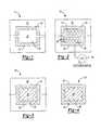
- FIG. 1is a schematic view of the tool assembly according to the present invention
- FIG. 2is a schematic view of the tool assembly filled with a powdered metal according to the present invention
- FIG. 3is a schematic view of the tool assembly after consolidation of the powdered metal according to the present invention.
- FIG. 4is a schematic view of a net-shaped bimetallic part with a diffusion bonded environmental surface according to the present invention.
- FIG. 1a schematic diagram of a tool assembly 10 .
- the tool assembly 10comprises a tool 12 having a pair of tool halves that cooperate to define a cavity 14 having a tooling surface 16 .
- the tooling surface 16may be machined to conform to a predetermined contour to provide net-shape or near net-shape forming capabilities.
- the tooling surface 16is preferably formed with a surface finish that conforms to the desired surface finish of the finished article.
- the tool 12is formed from a material with a carbon content that closely matches the carbon content of the environmental metal material 18 .
- the tool 12is made from a ferrous material, preferably high purity soft iron with low carbon content. However, it is not intended that the tool 12 be limited to a soft iron with low carbon content.
- a layer of an environmental metal material 18is deposited on the tooling surface 16 of the tool 12 creating an exposed inner surface 20 .
- the environmental metal material 18is deposited onto the tooling surface 16 by low pressure plasma spraying.
- various alternate methods of depositing the environmental metal material 18 onto the tooling surface 16may also be employed, including wire arc spraying, kinetic energy metallization, and direct laser deposition.
- the particular deposition method that is utilizedmust be capable of depositing the environmental metal material 18 onto the tooling surface 16 such that the amount of impurities in the layer of the environmental metal material 18 do not exceed a desired threshold.
- we employed an air plasma spraying deposition technique that introduced a significant quantity of Cr-oxide flakes into the layer of the environmental metal material 18which, as those skilled in the art will readily appreciate, are generally unacceptable for highly loaded structural components such as blisks.
- the methodology of the present inventionhas application to the fabrication of other components besides highly loaded structural components, those skilled in the art will appreciate that the method of the present invention in its broader aspects is not to be limited in scope to any particular deposition method.
- the environmental metal material 18is selected for its resistance to a given predetermined environmental condition, as well as its compatibility with the powdered metal material 22 .
- the environmental metal material 18may be made from a nickel, Ni—Cr or nickel-based superalloy for use in oxygen-rich environments, or an iron-based superalloy such as A286 for hydrogen-rich environments, or a 300-series stainless steel for peroxide-rich environments.
- the environmental metal material 18is not limited to these examples or compatibility in these environments.
- the cavity 14 of the tool 12is filled with a powdered metal material 22 .
- the powdered metal material 22is selected on the basis of various design criteria for the finished article.
- the basis for the selection of the powdered metal material 22is its strength and as such, a 720-alloy, which is well known in the art, was selected.
- the inventionis in no way limited to a particular criteria or characteristic for the selection of the powdered metal material 22 and that the powdered metal material 22 need not be limited to any specific alloy disclosed herein or to a high strength superalloy.
- the presence of voids within the finished bimetallic partis highly undesirable. Accordingly, it may be necessary and appropriate in certain situations to degas the powdered metal material 22 within the cavity 14 of the tool assembly 10 . As is well known in the art, various vacuum devices may be employed in a degassing operation.
- the tool assembly 10is sealed to prevent pressurized gasses from entering the tool assembly 10 during the next steps of the methodology.
- the tool assembly 10may be sealed in various different ways, including the use of high pressure seals between the halves of the tool assembly 10 .
- the halves of the tool assembly 10may be sealingly welded to one another.
- the tool assembly 10is placed in an autoclave (not shown) wherein the tool assembly 10 is simultaneously heated and subjected to a pressurized gas to hot isostatically press or consolidate the powdered metal material 22 and diffusion bond the environmental metal material 18 to the powdered metal material 22 .
- the environmental metal material 18limits carbon diffusion from the tool 12 to the powdered metal material 22 during the step of simultaneously heating and subjecting the tool to the pressurized gas.
- carbon diffusion into the environmental metal material 18may adversely affect certain properties, such as high cycle fatigue strength. Accordingly, it is highly desirable that the material for the tool 12 be selected to closely match its carbon content to the carbon content of the environmental metal material 18 to thereby significantly limit or eliminate altogether concerns for carbon diffusion.
- highly finishing the tooling surface 16along with the building-up the layer of the environmental metal material 18 to a sufficient thickness to prevent the powdered metal material 22 from indenting the tool 12 (as will be discussed below) may be employed to reduce the effectiveness of the mechanism that facilitates carbon diffusion to thereby further reduce concerns for carbon diffusion.
- the powdered metal material 22is consolidated to form an inner consolidated powder metal core 24 .
- the hot isostatic pressing operationworks to not only close all porosity in the consolidated powder metal core 24 , but also in the environmental metal material 18 if the environmental metal material 18 is deposited through a method, such as low pressure plasma spraying, for example, in which the deposit is not fully dense as deposited.
- the powder particles of the inner core 24indents the exposed inner surface 20 of environmental metal material 18 forming a rough interface 26 between the inner core 24 and the environmental metal material 18 .
- This rough interface 26provides greater surface area for the diffusion bond and mechanically breaks any oxide layer formed on the inner surface 20 of the environmental metal material 18 .
- the tool 12is removed from the inner core 24 and the environmental metal material 18 .
- the tool 12is deposited in an acid bath (not shown) that dissolves the tool 12 .
- the acidis selected on the basis of its reactivity with the material of the tool 12 and its non-reactivity with the environmental metal material 18 . Accordingly, those skilled in the art will appreciate that the tool 12 is sacrificial in the particular example provided.
- the net-shaped bimetallic part 28includes the inner core 24 at least partially surrounded by the environmental metal material 18 . As described above, the environmental metal material 18 is diffusion bonded to the inner core 24 . The environmental metal material 18 has a surface 30 matching that of the tooling surface 16 of the tool 12 .
- the net-shaped bimetallic part 28may be of any shape or configuration, for example a bladed disk (blisk) for use in a turbine, housings, manifolds, nozzles, preburners, etc.
Landscapes
- Engineering & Computer Science (AREA)
- Manufacturing & Machinery (AREA)
- Mechanical Engineering (AREA)
- Chemical & Material Sciences (AREA)
- Composite Materials (AREA)
- Materials Engineering (AREA)
- Other Surface Treatments For Metallic Materials (AREA)
- Powder Metallurgy (AREA)
Abstract
Description
Claims (32)
Priority Applications (1)
| Application Number | Priority Date | Filing Date | Title |
|---|---|---|---|
| US10/279,780US6939508B2 (en) | 2002-10-24 | 2002-10-24 | Method of manufacturing net-shaped bimetallic parts |
Applications Claiming Priority (1)
| Application Number | Priority Date | Filing Date | Title |
|---|---|---|---|
| US10/279,780US6939508B2 (en) | 2002-10-24 | 2002-10-24 | Method of manufacturing net-shaped bimetallic parts |
Publications (2)
| Publication Number | Publication Date |
|---|---|
| US20040081572A1 US20040081572A1 (en) | 2004-04-29 |
| US6939508B2true US6939508B2 (en) | 2005-09-06 |
Family
ID=32106806
Family Applications (1)
| Application Number | Title | Priority Date | Filing Date |
|---|---|---|---|
| US10/279,780Expired - LifetimeUS6939508B2 (en) | 2002-10-24 | 2002-10-24 | Method of manufacturing net-shaped bimetallic parts |
Country Status (1)
| Country | Link |
|---|---|
| US (1) | US6939508B2 (en) |
Cited By (6)
| Publication number | Priority date | Publication date | Assignee | Title |
|---|---|---|---|---|
| US20100008778A1 (en)* | 2007-12-13 | 2010-01-14 | Patrick D Keith | Monolithic and bi-metallic turbine blade dampers and method of manufacture |
| US20110058975A1 (en)* | 2009-09-10 | 2011-03-10 | Bampton Clifford C | Method of processing a bimetallic part |
| CN102369073A (en)* | 2009-04-03 | 2012-03-07 | 空中客车操作有限公司 | Hybrid component |
| US20130071627A1 (en)* | 2009-12-23 | 2013-03-21 | Geoffrey Frederick Archer | Hot isostatic pressing |
| US8778259B2 (en) | 2011-05-25 | 2014-07-15 | Gerhard B. Beckmann | Self-renewing cutting surface, tool and method for making same using powder metallurgy and densification techniques |
| US10364677B2 (en) | 2013-03-15 | 2019-07-30 | United Technologies Corporation | Turbine engine hybrid rotor |
Families Citing this family (7)
| Publication number | Priority date | Publication date | Assignee | Title |
|---|---|---|---|---|
| US8303289B2 (en)* | 2009-08-24 | 2012-11-06 | General Electric Company | Device and method for hot isostatic pressing container |
| US8727203B2 (en) | 2010-09-16 | 2014-05-20 | Howmedica Osteonics Corp. | Methods for manufacturing porous orthopaedic implants |
| RU2536124C1 (en)* | 2013-08-21 | 2014-12-20 | Открытое акционерное общество "Всероссийский институт легких сплавов" (ОАО "ВИЛС") | Obtaining method of gas-turbine engine wheel |
| US10675685B2 (en) | 2014-01-14 | 2020-06-09 | Raytheon Technologies Corporation | Method for preventing powder depletion/contamination during consolidation process |
| JP2017514993A (en)* | 2014-03-25 | 2017-06-08 | サンドビック インテレクチュアル プロパティー アクティエボラーグ | Method for manufacturing picklable metal components |
| US20170241429A1 (en)* | 2014-05-30 | 2017-08-24 | Nuovo Pignone Srl | Method of manufacturing a component of a turbomachine, component of turbomachine and turbomachine |
| CN105772718B (en)* | 2014-12-18 | 2018-07-17 | 北京有色金属研究总院 | A kind of dual alloy integral blade disc and preparation method thereof |
Citations (15)
| Publication number | Priority date | Publication date | Assignee | Title |
|---|---|---|---|---|
| US4023966A (en)* | 1975-11-06 | 1977-05-17 | United Technologies Corporation | Method of hot isostatic compaction |
| US4145481A (en)* | 1977-08-03 | 1979-03-20 | Howmet Turbine Components Corporation | Process for producing elevated temperature corrosion resistant metal articles |
| US4212669A (en)* | 1978-08-03 | 1980-07-15 | Howmet Turbine Components Corporation | Method for the production of precision shapes |
| US4383854A (en) | 1980-12-29 | 1983-05-17 | General Electric Company | Method of creating a controlled interior surface configuration of passages within a substrate |
| EP0090118A1 (en)* | 1982-03-26 | 1983-10-05 | Crucible Materials Corporation | Ceramic mould and method of producing same |
| US4421717A (en) | 1982-06-10 | 1983-12-20 | Ford Motor Company | Method of making wear resistant ferrous based parts |
| US4772450A (en)* | 1984-07-25 | 1988-09-20 | Trw Inc. | Methods of forming powdered metal articles |
| US5960249A (en)* | 1998-03-06 | 1999-09-28 | General Electric Company | Method of forming high-temperature components and components formed thereby |
| US6044555A (en) | 1998-05-04 | 2000-04-04 | Keystone Powered Metal Company | Method for producing fully dense powdered metal helical gear |
| US6132527A (en)* | 1996-04-24 | 2000-10-17 | Rolls-Royce Plc | Nickel alloy for turbine engine components |
| US6210633B1 (en) | 1999-03-01 | 2001-04-03 | Laboratory Of New Technologies | Method of manufacturing articles of complex shape using powder materials, and apparatus for implementing this method |
| US6224798B1 (en) | 2000-07-31 | 2001-05-01 | Delphi Technologies, Inc. | Method for fabricating powdered metal cores |
| US6250883B1 (en) | 1999-04-13 | 2001-06-26 | Alliedsignal Inc. | Integral ceramic blisk assembly |
| US6340424B1 (en) | 2000-08-17 | 2002-01-22 | General Electrical Company | Manufacture of complexly shaped articles using an automated design technique |
| US6410153B1 (en)* | 1999-02-22 | 2002-06-25 | Rolls-Royce Plc | Nickel based superalloy |
- 2002
- 2002-10-24USUS10/279,780patent/US6939508B2/ennot_activeExpired - Lifetime
Patent Citations (15)
| Publication number | Priority date | Publication date | Assignee | Title |
|---|---|---|---|---|
| US4023966A (en)* | 1975-11-06 | 1977-05-17 | United Technologies Corporation | Method of hot isostatic compaction |
| US4145481A (en)* | 1977-08-03 | 1979-03-20 | Howmet Turbine Components Corporation | Process for producing elevated temperature corrosion resistant metal articles |
| US4212669A (en)* | 1978-08-03 | 1980-07-15 | Howmet Turbine Components Corporation | Method for the production of precision shapes |
| US4383854A (en) | 1980-12-29 | 1983-05-17 | General Electric Company | Method of creating a controlled interior surface configuration of passages within a substrate |
| EP0090118A1 (en)* | 1982-03-26 | 1983-10-05 | Crucible Materials Corporation | Ceramic mould and method of producing same |
| US4421717A (en) | 1982-06-10 | 1983-12-20 | Ford Motor Company | Method of making wear resistant ferrous based parts |
| US4772450A (en)* | 1984-07-25 | 1988-09-20 | Trw Inc. | Methods of forming powdered metal articles |
| US6132527A (en)* | 1996-04-24 | 2000-10-17 | Rolls-Royce Plc | Nickel alloy for turbine engine components |
| US5960249A (en)* | 1998-03-06 | 1999-09-28 | General Electric Company | Method of forming high-temperature components and components formed thereby |
| US6044555A (en) | 1998-05-04 | 2000-04-04 | Keystone Powered Metal Company | Method for producing fully dense powdered metal helical gear |
| US6410153B1 (en)* | 1999-02-22 | 2002-06-25 | Rolls-Royce Plc | Nickel based superalloy |
| US6210633B1 (en) | 1999-03-01 | 2001-04-03 | Laboratory Of New Technologies | Method of manufacturing articles of complex shape using powder materials, and apparatus for implementing this method |
| US6250883B1 (en) | 1999-04-13 | 2001-06-26 | Alliedsignal Inc. | Integral ceramic blisk assembly |
| US6224798B1 (en) | 2000-07-31 | 2001-05-01 | Delphi Technologies, Inc. | Method for fabricating powdered metal cores |
| US6340424B1 (en) | 2000-08-17 | 2002-01-22 | General Electrical Company | Manufacture of complexly shaped articles using an automated design technique |
Cited By (11)
| Publication number | Priority date | Publication date | Assignee | Title |
|---|---|---|---|---|
| US20100008778A1 (en)* | 2007-12-13 | 2010-01-14 | Patrick D Keith | Monolithic and bi-metallic turbine blade dampers and method of manufacture |
| US8267662B2 (en) | 2007-12-13 | 2012-09-18 | General Electric Company | Monolithic and bi-metallic turbine blade dampers and method of manufacture |
| CN102369073A (en)* | 2009-04-03 | 2012-03-07 | 空中客车操作有限公司 | Hybrid component |
| CN102369073B (en)* | 2009-04-03 | 2014-07-23 | 空中客车操作有限公司 | Method of forming a hybrid component, method of joining the component to another component, and joint |
| US9085030B2 (en) | 2009-04-03 | 2015-07-21 | Airbus Operations Limited | Hybrid component |
| US20110058975A1 (en)* | 2009-09-10 | 2011-03-10 | Bampton Clifford C | Method of processing a bimetallic part |
| US9399258B2 (en)* | 2009-09-10 | 2016-07-26 | Aerojet Rocketdyne Of De, Inc. | Method of processing a bimetallic part |
| US20130071627A1 (en)* | 2009-12-23 | 2013-03-21 | Geoffrey Frederick Archer | Hot isostatic pressing |
| US9095902B2 (en)* | 2009-12-23 | 2015-08-04 | Advanced Interactive Materials Science Limited | Hot isostatic pressing |
| US8778259B2 (en) | 2011-05-25 | 2014-07-15 | Gerhard B. Beckmann | Self-renewing cutting surface, tool and method for making same using powder metallurgy and densification techniques |
| US10364677B2 (en) | 2013-03-15 | 2019-07-30 | United Technologies Corporation | Turbine engine hybrid rotor |
Also Published As
| Publication number | Publication date |
|---|---|
| US20040081572A1 (en) | 2004-04-29 |
Similar Documents
| Publication | Publication Date | Title |
|---|---|---|
| US11370026B2 (en) | Method for manufacture a metallic component by pre-manufactured bodies | |
| US6939508B2 (en) | Method of manufacturing net-shaped bimetallic parts | |
| US5890274A (en) | Method of producing a coating layer on a localized area of a superalloy component | |
| US5395699A (en) | Component, in particular turbine blade which can be exposed to high temperatures, and method of producing said component | |
| EP0550439A4 (en) | Powder metallurgy repair technique. | |
| US7112301B2 (en) | HIP manufacture of a hollow component | |
| EP0466401B1 (en) | Gear | |
| EP1527842B1 (en) | A method of manufacturing a fibre reinforced metal matrix composite article | |
| EP2340905B1 (en) | A method of manufacturing a component | |
| US20030217791A1 (en) | Method for producing a component and/or a coating comprised of a vibration-damping alloy or intermetallic compound, and component produced using this method | |
| JP2726753B2 (en) | Method for forming coating on sintered layer | |
| CA2440130C (en) | Corrosion resistant component and method for fabricating same | |
| JP4133078B2 (en) | Method for producing fiber reinforced metal | |
| EP3501697A1 (en) | A manufacturing method | |
| US20030106198A1 (en) | Methods of making wear resistant tooling systems to be used in high temperature casting and molding | |
| CN110193598A (en) | A method of manufacture austenitic iron alloy | |
| EP1604760B1 (en) | A method of manufacturing a component with a cellular structure by consolidating a coated metal powder | |
| US20230127804A1 (en) | Method for fabricating components using hybrid additive manufacturing and consolidation process | |
| JPS61223106A (en) | Production of high alloy clad product | |
| GB2419835A (en) | Method of diffusion bonding | |
| JP3257694B2 (en) | Manufacturing method of composite member | |
| CN113260731A (en) | Method of manufacturing a core | |
| JPH0483809A (en) | Compound gear and manufacture thereof | |
| JPH01275705A (en) | Manufacturing method for high-density sintered products |
Legal Events
| Date | Code | Title | Description |
|---|---|---|---|
| AS | Assignment | Owner name:BOEING COMPANY, THE, ILLINOIS Free format text:ASSIGNMENT OF ASSIGNORS INTEREST;ASSIGNORS:BAMPTON, CLIFFORD C.;SAMOROV, VICTOR;REEL/FRAME:013783/0691 Effective date:20030127 | |
| AS | Assignment | Owner name:BOEING COMPANY, THE, ILLINOIS Free format text:CORRECTED ASSIGNMENT TO CORRECT THE NAME OF THE SECOND INVENTOR PREVIOUSLY RECORDED ON REEL 013783 FRAME 0691.;ASSIGNORS:BAMPTON, CLIFFORD C.;SAMAROV, VICTOR;REEL/FRAME:015957/0578 Effective date:20030127 | |
| STCF | Information on status: patent grant | Free format text:PATENTED CASE | |
| FPAY | Fee payment | Year of fee payment:4 | |
| FPAY | Fee payment | Year of fee payment:8 | |
| AS | Assignment | Owner name:U.S. BANK NATIONAL ASSOCIATION, CALIFORNIA Free format text:SECURITY AGREEMENT;ASSIGNOR:PRATT & WHITNEY ROCKETDYNE, INC.;REEL/FRAME:030656/0615 Effective date:20130614 | |
| AS | Assignment | Owner name:AEROJET ROCKETDYNE OF DE, INC. (F/K/A PRATT & WHIT Free format text:LICENSE;ASSIGNOR:THE BOEING COMPANY AND BOEING MANAGEMENT COMPANY;REEL/FRAME:039595/0189 Effective date:20050802 Owner name:AEROJET ROCKETDYNE OF DE, INC. (F/K/A PRATT & WHIT Free format text:RELEASE BY SECURED PARTY;ASSIGNOR:U.S. BANK NATIONAL ASSOCIATION;REEL/FRAME:039597/0890 Effective date:20160715 | |
| FPAY | Fee payment | Year of fee payment:12 |