US6939021B2 - Triangular light assembly with flashing and non-flashing lights - Google Patents
Triangular light assembly with flashing and non-flashing lightsDownload PDFInfo
- Publication number
- US6939021B2 US6939021B2US10/858,713US85871304AUS6939021B2US 6939021 B2US6939021 B2US 6939021B2US 85871304 AUS85871304 AUS 85871304AUS 6939021 B2US6939021 B2US 6939021B2
- Authority
- US
- United States
- Prior art keywords
- light
- housing
- light emitting
- assembly
- emitting device
- Prior art date
- Legal status (The legal status is an assumption and is not a legal conclusion. Google has not performed a legal analysis and makes no representation as to the accuracy of the status listed.)
- Expired - Fee Related
Links
Images


Classifications
- B—PERFORMING OPERATIONS; TRANSPORTING
- B60—VEHICLES IN GENERAL
- B60Q—ARRANGEMENT OF SIGNALLING OR LIGHTING DEVICES, THE MOUNTING OR SUPPORTING THEREOF OR CIRCUITS THEREFOR, FOR VEHICLES IN GENERAL
- B60Q7/00—Arrangement or adaptation of portable emergency signal devices on vehicles
Definitions
- the present inventionrelates to a light assembly, and in particular to a light assembly that includes both flashing warning lights and non-flashing lights for viewing objects.
- Disabled vehicles on highways, local and/or inner city streetsmay cause traffic jams, as well as blocking a shoulder or a portion of the roadway depending upon the location of the disabled vehicle.
- One typical means for notifying oncoming motorists that a vehicle is disabledis the use of flares.
- the operatormay desire a flashlight for use during repair to the vehicle. For example, an operator changing a tire at nighttime will require the use of flashlight.
- a portable device for use in the vehiclewhich provides the dual functions of a light source as well as a signaling device for other motorists, highway patrolmen, truck drivers and tow truck drivers.
- a light assemblythat includes a generally triangular shaped housing having a front surface and a back surface opposite the front surface.
- the light assemblyfurther includes at least a first light-emitting device disposed in the housing configured to emit a non-flashing light from the front surface of the housing.
- the light assemblyincludes at least a second light-emitting device disposed in the housing configured to emit a flashing light from the back surface of the housing.
- triangular shaped objectsgenerally denote a warning to vehicular motorists.
- the generally triangular shaped light assemblyshould be readily recognized as a warning light to vehicular motorists.
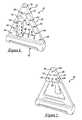
- FIG. 1is a rear perspective view of an exemplary embodiment of a light assembly.
- FIG. 2is a front perspective view of an exemplary embodiment of the light assembly.
- FIG. 3is a side view of an exemplary embodiment of the light assembly.
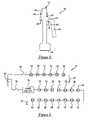
- FIG. 4is a schematic of an electrical circuit utilized in an exemplary embodiment of the light assembly.
- FIG. 5is a rear view of another exemplary embodiment of a light assembly.
- FIG. 6is a side cross-sectional view of another exemplary embodiment of the light assembly.
- FIG. 7is a bottom view of a rotatable base utilized in another exemplary embodiment of the light assembly.
- FIG. 8is a front view of another exemplary embodiment of the light assembly, excluding the rotatable base.
- FIG. 9is a schematic of an electrical circuit utilized in an exemplary embodiment of the light assembly.
- Light assembly 10having both the functionality of a warning light and a flashlight in accordance with an exemplary embodiment is illustrated.
- Light assembly 10includes a housing 12 , a rotatable base 14 , and an electrical circuit 16 .
- housing 12includes a front housing portion 60 , a rear housing portion 62 , and a transparent lens 64 .
- Housing portions 60 , 62are preferably coupled together with screws (not shown). Further, housing portions 60 , 62 define an interior space configured to hold therein the electrical circuit 16 which includes a plurality of light emitting diodes.
- Front housing portion 60is preferably constructed from an opaque plastic.
- Rear housing portion 62is preferably constructed from a substantially transparent plastic having a substantially red color.
- rear housing portion 62includes an outer surface 70 from which light is emitted.
- the housing portion 62further includes a handle 66 to allow a user of light assembly 10 to move assembly 10 easily.
- handle 66allows a user to easily direct the light source of light-emitting diodes 18 – 28 towards an area requiring illumination.
- Handle 66is split at dashed line 71 and can rotate about a pivot point or hinge 69 toward surface 70 for ease of storage of light assembly 10 . Further, handle 66 can be rotated about pivot point 69 to the position shown in FIG. 1 to allow a user to easily hold light assembly 10 in their hand.
- Transparent lens 64includes an outer surface 65 from which light is emitted. Lens 64 is preferably constructed from a transparent clear plastic.
- Rotatable base 14is provided to allow housing 12 to be rotated relative to base 14 to a desired position.
- Rotatable base 14is preferably constructed from plastic and is rotatably coupled to housing 12 utilizing a screw (not shown).
- the rotatable base 14can be rotatably positioned under housing 12 for flat storage of the light assembly 10 .
- the rotatable base 14also supports the housing 12 in an upright position when the base is disposed on an irregular or non-flat surface.
- electrical circuit 16includes a voltage source 90 , first and second switches 92 , 94 , a timer circuit 96 , and light emitting diodes (LEDS) 18 , 20 , 22 , 24 , 26 , 28 , 30 , 32 , 34 , 36 , 38 , 40 , 42 , 44 , 46 , 48 , 50 , 52 , 54 , 56 , 58 .
- Voltage source 90may comprise a conventional battery.
- Switches 92 , 94may comprise conventional normally-open contact switches. As shown, switch 92 is connected in series between voltage source 90 and LEDs 18 – 28 . When switch 92 is moved to a closed operational position, LEDs 18 – 28 emit light that propagates through transparent lens 64 .
- Circuit 96is a conventional timer circuit which periodically energizes LEDs 30 – 58 so that LEDs 30 – 58 flash at periodic intervals.
- Circuit 96comprises the timer circuit disclosed in U.S. Pat. No. 5,627,513, entitled “Portable Visual Emergency Signal Device” filed on Apr. 25, 1995, which is incorporated herein in its entirety.
- a plurality of other configurations of timer circuit 96could be utilized in light assembly 10 .
- LEDs 30 – 58are connected in series between timer circuit 96 and a ground 97 .
- LEDs 18 – 28are disposed within transparent lens 64 and emit substantially white light from surface 65 of lens 64 .
- LEDs 18 – 28may be mounted on one or more PCB boards (not shown). When a user of light assembly 10 actuates switch 92 , LEDs 18 – 28 may emit light that can be used for viewing objects at night. It should be noted that in an alternate embodiment one more of LEDs 18 – 28 could be replaced with halogen bulbs or other equivalent light emitting sources.
- LEDs 30 – 58are disposed within housing 12 proximate rear housing portion 62 .
- LEDs 30 – 58may be mounted on one or more PCB boards (not shown) disposed within housing 12 .
- rear housing portion 62is constructed from a substantially transparent red plastic.
- the emitted light through a surface 70 of rear housing portion 62has a substantially red color.
- LEDs 30 – 58may be periodically flashed by timer circuit 96 .
- a user of light assembly 10can move switch 94 to a closed operational position to obtain a flashing warning light that can be used at night to warn other people that a person or a vehicle is proximate the light assembly 10 .
- one more of LEDs 30 – 58could be replaced with halogen bulbs or any other type of electrically or chemically activated light emitting device.
- Light assembly 108having both the functionality of a warning light and a flashlight in accordance with another exemplary embodiment is illustrated.
- Light assembly 108includes a housing 109 , a transparent lens 114 , a rotatable base 116 , and an electrical circuit 118 .
- housing 109includes a front housing portion 110 and a rear housing portion 112 .
- Housing portions 110 , 112are preferably coupled together with screws and may have an O-ring gasket (not shown) disposed therebetween. Further, housing portions 110 , 112 define an interior space configured to hold therein electrical circuit 118 which may includes a plurality of PCB boards, light emitting diodes, and batteries described below.
- Front housing portion 110is preferably constructed from an opaque plastic.
- Rear housing portion 112is preferably constructed from a substantially transparent plastic having a substantially red color. As shown, rear housing portion 112 includes an outer surface 113 from which light is emitted.
- Housing portion 112further includes a handle 120 to allow a user of light assembly 108 to move assembly 108 easily. Housing portion 112 further includes an eyelet 115 coupled to an upper portion of rear housing portion 112 to allow light assembly 108 to be hung above the ground.
- transparent lens 114includes an outer surface 122 from which light is emitted.
- Lens 114is preferably constructed from a transparent clear plastic and may be coupled to housing portion 110 using screws or may be configured to snap into housing portion 110 .
- Rotatable base 116is provided to allow housing 109 to be rotated relative to base 116 .
- Base 116is preferably constructed from plastic and may be rotatably coupled to housing 109 utilizing a screw 117 .
- screw 117could be replaced with a dowel pin that would also allow base 116 to rotate relative to housing 109 .
- the base 116can be rotated from a stored position to a deployed position by rotating base 116 so that two ends of base 116 are disposed outwardly from the remainder of the housing 109 for providing multiple surface areas for supporting the light assembly 108 .
- the additional surfaceswill provide a more stable support of the light assembly 108 on non-flat surfaces or when vehicles driving past the light assembly 108 induce wind gusts against the assembly.
- electrical circuit 118includes batteries 150 , 152 , 155 , and 156 , a switch mechanism 148 , a timer circuit 96 , LEDS 130 , 132 , 134 , 136 , 138 , 140 , 142 , 144 , 146 , 160 , 162 , 164 , 166 , a low battery detection circuit 172 , and a speaker 174 .
- switch 148is connected in series between batteries 150 , 152 , 155 , 156 and LEDs 160 – 166 .
- LEDs 160 – 166may be electrically connected in series and disposed on a PCB board 159 that is fixedly mounted within housing portion 110 .
- LEDs 160 – 166may be mounted at a 10 degree angle with respect to a vertical axis extending through assembly 108 .
- switch mechanism 148When a member (not shown) of switch mechanism 148 is depressed once, LEDs 160 – 166 are configured to transmit substantially white light through lens 114 .
- LEDs 130 – 146may be electrically connected in series between timer circuit 96 and ground 147 . Further, LEDs 130 – 146 are mounted on one or more PCB boards. LEDs 130 , 132 , 134 are mounted on a PCB board 124 which is fixedly attached within an interior of housing 109 . LEDs 136 , 138 , 140 are mounted on a PCB board 126 which is fixedly attached within an interior of housing 109 . Further, LEDs 142 , 144 , 146 are mounted on a PCB board 128 which is fixedly attached within an interior of housing 109 . Referring to FIGS.
- LEDs 130 – 146are disposed within housing 109 proximate rear housing portion 112 .
- rear housing portion 112is constructed from a substantially transparent red plastic.
- the emitted light through a surface 113 of rear housing portion 112has a substantially red color.
- circuit 96is a conventional timer circuit and may comprise the timer circuit disclosed in U.S. Pat. No. 5,627,513, entitled “Portable Visual Emergency Signal Device” filed on Apr. 25, 1995, which is incorporated herein in its entirety.
- Timer circuit 96is electrically connected in series with LEDs 130 – 146 to periodically energize LEDS 130 – 146 to emit a flashing light.
- circuit 96could be removed so that LEDS 130 – 146 would be directly coupled in series with switch mechanism 148 so that LEDs 130 – 146 would emit a non-flashing light when LEDs 130 – 146 are energized.
- Switch mechanism 148is further connected in series between batteries 150 , 152 , 155 , 156 and timer circuit 96 .
- a member (not shown) of switch mechanism 148When a member (not shown) of switch mechanism 148 is depressed a first time, LEDs 160 – 166 are energized and emit light through transparent lens 114 .
- timer circuit 96When the member of switch mechanism 148 is depressed a second time, timer circuit 96 is energized. Thereafter, circuit 96 induces LEDs 130 – 146 to emit a blinking red light at periodic intervals through rear housing portion 112 .
- the member of switch mechanism 148When the member of switch mechanism 148 is depressed a third time, all of the LEDs of circuit 118 are turned off.
- LEDs 130 – 146 and 160 – 166provide a relatively high intensity light with a relatively low power consumption. It should be noted that in an alternate embodiment of light assembly 108 , one or more of LEDs 160 – 166 and LEDs 130 – 146 could be replaced with halogen bulbs or any other type of electrically or chemically activated light emitting device.
- Low battery detection circuit 172is provided to determine when an operational voltage produced by batteries 156 , 155 , 152 , and 150 is less than a desired operational voltage.
- Circuit 172can be implemented using conventional circuit components such as solid state comparator circuits for example.
- Circuit 172is electrically coupled to a node 170 between battery 155 and switch mechanism 148 .
- circuit 172detects an operational voltage at node 170 less than the desired operational voltage, circuit 172 generates a signal that induces speaker 174 to generate an audible beeping sound. The beeping sound will indicate to a user that the batteries 156 , 155 , 152 , 150 need to be replaced.
- inventive light assemblyprovides substantial advantages over known light assemblies.
- inventive light assembliesprovide a dual function of a light source as well as a signaling device for other motorists, highway patrolmen, truck drivers and tow truck drivers.
- inventive light assembliesare portable and storable within a vehicle.
Landscapes
- Engineering & Computer Science (AREA)
- Mechanical Engineering (AREA)
- Arrangement Of Elements, Cooling, Sealing, Or The Like Of Lighting Devices (AREA)
- Non-Portable Lighting Devices Or Systems Thereof (AREA)
Abstract
Description
Claims (18)
Priority Applications (1)
| Application Number | Priority Date | Filing Date | Title |
|---|---|---|---|
| US10/858,713US6939021B2 (en) | 2003-12-18 | 2004-06-02 | Triangular light assembly with flashing and non-flashing lights |
Applications Claiming Priority (2)
| Application Number | Priority Date | Filing Date | Title |
|---|---|---|---|
| US53057803P | 2003-12-18 | 2003-12-18 | |
| US10/858,713US6939021B2 (en) | 2003-12-18 | 2004-06-02 | Triangular light assembly with flashing and non-flashing lights |
Publications (2)
| Publication Number | Publication Date |
|---|---|
| US20050135092A1 US20050135092A1 (en) | 2005-06-23 |
| US6939021B2true US6939021B2 (en) | 2005-09-06 |
Family
ID=34681583
Family Applications (1)
| Application Number | Title | Priority Date | Filing Date |
|---|---|---|---|
| US10/858,713Expired - Fee RelatedUS6939021B2 (en) | 2003-12-18 | 2004-06-02 | Triangular light assembly with flashing and non-flashing lights |
Country Status (1)
| Country | Link |
|---|---|
| US (1) | US6939021B2 (en) |
Cited By (11)
| Publication number | Priority date | Publication date | Assignee | Title |
|---|---|---|---|---|
| US20050083692A1 (en)* | 2003-08-08 | 2005-04-21 | Leen Monte A. | Multiple head worklight |
| US20060232962A1 (en)* | 2005-04-14 | 2006-10-19 | Safe And Sound Safety Corporation | Hazard marker kit |
| US20070030680A1 (en)* | 2005-08-02 | 2007-02-08 | Wen-Hsin Chao | Warning device having light emitting effect |
| US20080001337A1 (en)* | 2006-06-30 | 2008-01-03 | Junior Hsu | Cutting board with pivoting base |
| US20080088477A1 (en)* | 2006-10-13 | 2008-04-17 | Louis Martin | Omnidirectional universal mount hazard marker |
| US20090090291A1 (en)* | 2007-10-09 | 2009-04-09 | Clothier Steven R | Signal and marker tool |
| US20090250860A1 (en)* | 2006-06-30 | 2009-10-08 | Junior Hsu | Cutting board with pivotal base stand |
| US7717586B2 (en) | 2007-01-18 | 2010-05-18 | E-Z Red Company | Foldable light |
| USD701342S1 (en)* | 2012-05-25 | 2014-03-18 | Joshua David Company | Light fixture assembly |
| USD703488S1 (en)* | 2012-08-31 | 2014-04-29 | Antonio Manuel De Veiga Martins | Water bottle warning triangle |
| DE202016007685U1 (en) | 2016-12-20 | 2018-03-21 | GM Global Technology Operations LLC (n. d. Ges. d. Staates Delaware) | Motor vehicle with warning sign |
Families Citing this family (4)
| Publication number | Priority date | Publication date | Assignee | Title |
|---|---|---|---|---|
| EP1752337A1 (en)* | 2005-08-12 | 2007-02-14 | Wen-Hsin Chao | Illuminated warning triangle |
| US20100242337A1 (en)* | 2009-03-30 | 2010-09-30 | Steve Cummings | Ice fishing device |
| US8646938B1 (en)* | 2009-04-21 | 2014-02-11 | Morton Sunshine | Distress marker system |
| AT517709B1 (en)* | 2015-10-14 | 2017-04-15 | Thomas Kurt Stelzl | signal light |
Citations (23)
| Publication number | Priority date | Publication date | Assignee | Title |
|---|---|---|---|---|
| US4164008A (en)* | 1977-02-24 | 1979-08-07 | Stanley M. Meyer | Illuminated article of clothing |
| US4613847A (en)* | 1983-08-08 | 1986-09-23 | Life Light Systems | Emergency signal |
| US4734832A (en)* | 1986-05-23 | 1988-03-29 | Tekna | Spotlight with interchangeable handle |
| US4875028A (en)* | 1986-03-26 | 1989-10-17 | Chou An Chuan | Warning triangle |
| US4952910A (en)* | 1988-03-05 | 1990-08-28 | Straten Guenter | Warning triangle for motor vehicles |
| US5019951A (en)* | 1989-11-28 | 1991-05-28 | Rayovac Corporation | Spotlight with adjustable handle |
| US5122939A (en)* | 1991-06-07 | 1992-06-16 | David Kazdan | Safety lighting and reflector system |
| US5349346A (en) | 1993-07-01 | 1994-09-20 | Wu Shin Chyuan | Reflector-warning triangle |
| US5419065A (en)* | 1993-11-17 | 1995-05-30 | Lin; Shih-Chiang | Illuminated distress warning sign |
| US5512876A (en) | 1989-12-12 | 1996-04-30 | Brusca; Vincenzo | Device for the timed lighting of signal triangles on vehicles and of triangles for emergency stops |
| US5558427A (en)* | 1994-05-25 | 1996-09-24 | Yang; Chang A. | Base structure for a three section type third braking light which can be converted into a triangular failure warning light |
| US5559681A (en)* | 1994-05-13 | 1996-09-24 | Cnc Automation, Inc. | Flexible, self-adhesive, modular lighting system |
| US5606309A (en)* | 1995-01-31 | 1997-02-25 | Smith; Frank | Road hazard warning apparatus |
| US5627513A (en)* | 1995-04-25 | 1997-05-06 | Weed; Leonard E. | Portable visual emergency signal device |
| US5651636A (en)* | 1996-01-03 | 1997-07-29 | Yeh; A-Chien | Traffic warning device |
| US5775253A (en)* | 1996-04-24 | 1998-07-07 | Beijing Success Electronic Company Limited | Warning triangle |
| US5970639A (en)* | 1998-06-04 | 1999-10-26 | Hui; Liao Chih | Innovated type of hazard alarm sign |
| US6092318A (en)* | 1996-01-24 | 2000-07-25 | Sanyo Electric Co., Ltd. | Solar battery type indication apparatus |
| US6275149B1 (en)* | 1999-10-14 | 2001-08-14 | Rong-Fang Tung | Illuminant triangular warning arrangement |
| US6389720B1 (en) | 2000-04-20 | 2002-05-21 | Chin-Keng Hsieh | Triangle road sign with solar power-driven flashing light means |
| US6419377B1 (en)* | 2001-01-19 | 2002-07-16 | Se Kit Yuen | Swivel lantern |
| US6535117B2 (en) | 2001-04-09 | 2003-03-18 | Bernell G. Haerer | Illumination device for safety triangle |
| US6543165B2 (en)* | 2001-01-23 | 2003-04-08 | Paul V Youseph | Folding traffic warning device |
- 2004
- 2004-06-02USUS10/858,713patent/US6939021B2/ennot_activeExpired - Fee Related
Patent Citations (24)
| Publication number | Priority date | Publication date | Assignee | Title |
|---|---|---|---|---|
| US4164008A (en)* | 1977-02-24 | 1979-08-07 | Stanley M. Meyer | Illuminated article of clothing |
| US4613847A (en)* | 1983-08-08 | 1986-09-23 | Life Light Systems | Emergency signal |
| US4875028A (en)* | 1986-03-26 | 1989-10-17 | Chou An Chuan | Warning triangle |
| US4734832A (en)* | 1986-05-23 | 1988-03-29 | Tekna | Spotlight with interchangeable handle |
| US4952910A (en)* | 1988-03-05 | 1990-08-28 | Straten Guenter | Warning triangle for motor vehicles |
| US5019951A (en)* | 1989-11-28 | 1991-05-28 | Rayovac Corporation | Spotlight with adjustable handle |
| US5512876A (en) | 1989-12-12 | 1996-04-30 | Brusca; Vincenzo | Device for the timed lighting of signal triangles on vehicles and of triangles for emergency stops |
| US5122939A (en)* | 1991-06-07 | 1992-06-16 | David Kazdan | Safety lighting and reflector system |
| US5349346A (en) | 1993-07-01 | 1994-09-20 | Wu Shin Chyuan | Reflector-warning triangle |
| US5419065A (en)* | 1993-11-17 | 1995-05-30 | Lin; Shih-Chiang | Illuminated distress warning sign |
| US5559681A (en)* | 1994-05-13 | 1996-09-24 | Cnc Automation, Inc. | Flexible, self-adhesive, modular lighting system |
| US5558427A (en)* | 1994-05-25 | 1996-09-24 | Yang; Chang A. | Base structure for a three section type third braking light which can be converted into a triangular failure warning light |
| US5606309A (en)* | 1995-01-31 | 1997-02-25 | Smith; Frank | Road hazard warning apparatus |
| US5627513A (en)* | 1995-04-25 | 1997-05-06 | Weed; Leonard E. | Portable visual emergency signal device |
| US5831522A (en) | 1995-04-25 | 1998-11-03 | Weed; Leonard E. | Portable visual emergency signal device |
| US5651636A (en)* | 1996-01-03 | 1997-07-29 | Yeh; A-Chien | Traffic warning device |
| US6092318A (en)* | 1996-01-24 | 2000-07-25 | Sanyo Electric Co., Ltd. | Solar battery type indication apparatus |
| US5775253A (en)* | 1996-04-24 | 1998-07-07 | Beijing Success Electronic Company Limited | Warning triangle |
| US5970639A (en)* | 1998-06-04 | 1999-10-26 | Hui; Liao Chih | Innovated type of hazard alarm sign |
| US6275149B1 (en)* | 1999-10-14 | 2001-08-14 | Rong-Fang Tung | Illuminant triangular warning arrangement |
| US6389720B1 (en) | 2000-04-20 | 2002-05-21 | Chin-Keng Hsieh | Triangle road sign with solar power-driven flashing light means |
| US6419377B1 (en)* | 2001-01-19 | 2002-07-16 | Se Kit Yuen | Swivel lantern |
| US6543165B2 (en)* | 2001-01-23 | 2003-04-08 | Paul V Youseph | Folding traffic warning device |
| US6535117B2 (en) | 2001-04-09 | 2003-03-18 | Bernell G. Haerer | Illumination device for safety triangle |
Cited By (15)
| Publication number | Priority date | Publication date | Assignee | Title |
|---|---|---|---|---|
| US7001044B2 (en)* | 2003-08-08 | 2006-02-21 | Leen Monte A | Multiple head worklight |
| US20050083692A1 (en)* | 2003-08-08 | 2005-04-21 | Leen Monte A. | Multiple head worklight |
| US20060232962A1 (en)* | 2005-04-14 | 2006-10-19 | Safe And Sound Safety Corporation | Hazard marker kit |
| US20070030680A1 (en)* | 2005-08-02 | 2007-02-08 | Wen-Hsin Chao | Warning device having light emitting effect |
| US8123206B2 (en) | 2006-06-30 | 2012-02-28 | Junior Hsu | Cutting board with pivotal base stand |
| US20080001337A1 (en)* | 2006-06-30 | 2008-01-03 | Junior Hsu | Cutting board with pivoting base |
| US8136806B2 (en) | 2006-06-30 | 2012-03-20 | Junior Hsu | Cutting board with pivoting base |
| US20090250860A1 (en)* | 2006-06-30 | 2009-10-08 | Junior Hsu | Cutting board with pivotal base stand |
| US20080088477A1 (en)* | 2006-10-13 | 2008-04-17 | Louis Martin | Omnidirectional universal mount hazard marker |
| US7623026B2 (en) | 2006-10-13 | 2009-11-24 | TotalFlare, Inc. | Omni directional universal mount hazard marker |
| US7717586B2 (en) | 2007-01-18 | 2010-05-18 | E-Z Red Company | Foldable light |
| US20090090291A1 (en)* | 2007-10-09 | 2009-04-09 | Clothier Steven R | Signal and marker tool |
| USD701342S1 (en)* | 2012-05-25 | 2014-03-18 | Joshua David Company | Light fixture assembly |
| USD703488S1 (en)* | 2012-08-31 | 2014-04-29 | Antonio Manuel De Veiga Martins | Water bottle warning triangle |
| DE202016007685U1 (en) | 2016-12-20 | 2018-03-21 | GM Global Technology Operations LLC (n. d. Ges. d. Staates Delaware) | Motor vehicle with warning sign |
Also Published As
| Publication number | Publication date |
|---|---|
| US20050135092A1 (en) | 2005-06-23 |
Similar Documents
| Publication | Publication Date | Title |
|---|---|---|
| US6939021B2 (en) | Triangular light assembly with flashing and non-flashing lights | |
| US6206541B1 (en) | Roadside emergency security flashlight | |
| US4952910A (en) | Warning triangle for motor vehicles | |
| US5276424A (en) | Attention getting sign | |
| US6963275B2 (en) | Portable warning light apparatus | |
| JP2749760B2 (en) | Signaling means | |
| US5585783A (en) | Marker light utilizing light emitting diodes disposed on a flexible circuit board | |
| US20080088477A1 (en) | Omnidirectional universal mount hazard marker | |
| US20030132852A1 (en) | Illuminated emergency signaling device | |
| JP3832955B2 (en) | Traffic safety system | |
| GB2338938A (en) | A bicycle pedal with selectively energised light emitting diodes | |
| US20030033739A1 (en) | Safety lighting device | |
| US7134765B2 (en) | Light dispersion device | |
| KR100647534B1 (en) | Intelligent safety signs for cars | |
| JP3831231B2 (en) | Car stop | |
| JP3002131U (en) | Portable light | |
| JPH09195232A (en) | Alarm lamp | |
| JP2000200502A (en) | Light emitting body for security display | |
| KR200353642Y1 (en) | Intelligent warning triangles | |
| JP2000040403A (en) | Luminous device for safety sign | |
| KR200273381Y1 (en) | Safety signal lamp | |
| KR950001952Y1 (en) | Emergency display lamp using solar cell in a street | |
| TWI656049B (en) | Vehicle light detecting device | |
| JP3013923U (en) | Warning lamp for umbrella | |
| JP2583501Y2 (en) | Pedestrian crossing lighting |
Legal Events
| Date | Code | Title | Description |
|---|---|---|---|
| AS | Assignment | Owner name:HONEYWELL INTERNATIONAL, INC., NEW JERSEY Free format text:ASSIGNMENT OF ASSIGNORS INTEREST;ASSIGNORS:LESLIE, STUART;ZEDER, ROLAND;REEL/FRAME:015432/0579 Effective date:20040528 | |
| FPAY | Fee payment | Year of fee payment:4 | |
| AS | Assignment | Owner name:FRAM GROUP IP LLC, NEW ZEALAND Free format text:ASSIGNMENT OF ASSIGNORS INTEREST;ASSIGNOR:HONEYWELL INTERNATIONAL INC.;REEL/FRAME:026671/0907 Effective date:20110729 | |
| AS | Assignment | Owner name:CREDIT SUISSE AG, AS FIRST LIEN COLLATERAL AGENT, Free format text:SECURITY AGREEMENT;ASSIGNORS:FRAM GROUP IP LLC;PRESTONE PRODUCTS CORPORATION;REEL/FRAME:026732/0670 Effective date:20110729 | |
| AS | Assignment | Owner name:CREDIT SUISSE AG, AS SECOND LIEN COLLATERAL AGENT, Free format text:SECURITY AGREEMENT;ASSIGNORS:FRAM GROUP IP LLC;PRESTONE PRODUCTS CORPORATION;REEL/FRAME:026740/0089 Effective date:20110729 | |
| REMI | Maintenance fee reminder mailed | ||
| LAPS | Lapse for failure to pay maintenance fees | ||
| STCH | Information on status: patent discontinuation | Free format text:PATENT EXPIRED DUE TO NONPAYMENT OF MAINTENANCE FEES UNDER 37 CFR 1.362 | |
| FP | Lapsed due to failure to pay maintenance fee | Effective date:20130906 | |
| AS | Assignment | Owner name:FRAM GROUP IP LLC, ILLINOIS Free format text:RELEASE BY SECURED PARTY;ASSIGNOR:CREDIT SUISSE AG, CAYMAN ISLANDS BRANCH, AS COLLATERAL AGENT;REEL/FRAME:041189/0938 Effective date:20161223 Owner name:FRAM GROUP IP LLC, ILLINOIS Free format text:RELEASE BY SECURED PARTY;ASSIGNOR:CREDIT SUISSE AG, CAYMAN ISLANDS BRANCH, AS COLLATERAL AGENT;REEL/FRAME:041189/0782 Effective date:20161223 |