US6938716B1 - Concrete mixing truck anti-rollover system - Google Patents
Concrete mixing truck anti-rollover systemDownload PDFInfo
- Publication number
- US6938716B1 US6938716B1US10/391,147US39114703AUS6938716B1US 6938716 B1US6938716 B1US 6938716B1US 39114703 AUS39114703 AUS 39114703AUS 6938716 B1US6938716 B1US 6938716B1
- Authority
- US
- United States
- Prior art keywords
- drum
- truck
- rollover
- load
- chassis
- Prior art date
- Legal status (The legal status is an assumption and is not a legal conclusion. Google has not performed a legal analysis and makes no representation as to the accuracy of the status listed.)
- Expired - Fee Related, expires
Links
- NJPPVKZQTLUDBO-UHFFFAOYSA-NnovaluronChemical compoundC1=C(Cl)C(OC(F)(F)C(OC(F)(F)F)F)=CC=C1NC(=O)NC(=O)C1=C(F)C=CC=C1FNJPPVKZQTLUDBO-UHFFFAOYSA-N0.000claimsdescription49
- 230000001133accelerationEffects0.000claimsdescription10
- 238000000034methodMethods0.000claimsdescription10
- 230000005540biological transmissionEffects0.000claimsdescription7
- 230000000977initiatory effectEffects0.000claims8
- 238000005096rolling processMethods0.000abstractdescription5
- 230000005484gravityEffects0.000description12
- 239000004568cementSubstances0.000description3
- 230000000694effectsEffects0.000description3
- 230000003247decreasing effectEffects0.000description2
- 238000010586diagramMethods0.000description2
- 238000012544monitoring processMethods0.000description1
- 238000003825pressingMethods0.000description1
- 239000000725suspensionSubstances0.000description1
- 230000000007visual effectEffects0.000description1
Images


Classifications
- B—PERFORMING OPERATIONS; TRANSPORTING
- B28—WORKING CEMENT, CLAY, OR STONE
- B28C—PREPARING CLAY; PRODUCING MIXTURES CONTAINING CLAY OR CEMENTITIOUS MATERIAL, e.g. PLASTER
- B28C5/00—Apparatus or methods for producing mixtures of cement with other substances, e.g. slurries, mortars, porous or fibrous compositions
- B28C5/42—Apparatus specially adapted for being mounted on vehicles with provision for mixing during transport
- B28C5/4203—Details; Accessories
- B28C5/4206—Control apparatus; Drive systems, e.g. coupled to the vehicle drive-system
- B28C5/4227—Transmission control mechanisms
- B—PERFORMING OPERATIONS; TRANSPORTING
- B28—WORKING CEMENT, CLAY, OR STONE
- B28C—PREPARING CLAY; PRODUCING MIXTURES CONTAINING CLAY OR CEMENTITIOUS MATERIAL, e.g. PLASTER
- B28C5/00—Apparatus or methods for producing mixtures of cement with other substances, e.g. slurries, mortars, porous or fibrous compositions
- B28C5/42—Apparatus specially adapted for being mounted on vehicles with provision for mixing during transport
- B28C5/4203—Details; Accessories
- B28C5/4206—Control apparatus; Drive systems, e.g. coupled to the vehicle drive-system
- B28C5/422—Controlling or measuring devices
- B28C5/4224—Roll-over prevention
- B—PERFORMING OPERATIONS; TRANSPORTING
- B28—WORKING CEMENT, CLAY, OR STONE
- B28C—PREPARING CLAY; PRODUCING MIXTURES CONTAINING CLAY OR CEMENTITIOUS MATERIAL, e.g. PLASTER
- B28C5/00—Apparatus or methods for producing mixtures of cement with other substances, e.g. slurries, mortars, porous or fibrous compositions
- B28C5/42—Apparatus specially adapted for being mounted on vehicles with provision for mixing during transport
- B28C5/4203—Details; Accessories
- B28C5/4265—Mounting means for drums; Support frames
- B—PERFORMING OPERATIONS; TRANSPORTING
- B60—VEHICLES IN GENERAL
- B60P—VEHICLES ADAPTED FOR LOAD TRANSPORTATION OR TO TRANSPORT, TO CARRY, OR TO COMPRISE SPECIAL LOADS OR OBJECTS
- B60P3/00—Vehicles adapted to transport, to carry or to comprise special loads or objects
- B60P3/16—Vehicles adapted to transport, to carry or to comprise special loads or objects for carrying mixed concrete, e.g. having rotatable drums
- B—PERFORMING OPERATIONS; TRANSPORTING
- B62—LAND VEHICLES FOR TRAVELLING OTHERWISE THAN ON RAILS
- B62D—MOTOR VEHICLES; TRAILERS
- B62D37/00—Stabilising vehicle bodies without controlling suspension arrangements
- B—PERFORMING OPERATIONS; TRANSPORTING
- B62—LAND VEHICLES FOR TRAVELLING OTHERWISE THAN ON RAILS
- B62D—MOTOR VEHICLES; TRAILERS
- B62D49/00—Tractors
- B62D49/08—Tractors having means for preventing overturning or tipping
- B—PERFORMING OPERATIONS; TRANSPORTING
- B62—LAND VEHICLES FOR TRAVELLING OTHERWISE THAN ON RAILS
- B62D—MOTOR VEHICLES; TRAILERS
- B62D61/00—Motor vehicles or trailers, characterised by the arrangement or number of wheels, not otherwise provided for, e.g. four wheels in diamond pattern
- B62D61/12—Motor vehicles or trailers, characterised by the arrangement or number of wheels, not otherwise provided for, e.g. four wheels in diamond pattern with variable number of ground engaging wheels, e.g. with some wheels arranged higher than others, or with retractable wheels
Definitions
- the present inventionis an anti-rollover system to prevent rollovers of a concrete mixing truck.
- the anti-rollover systemprovides input data representative of operating conditions of the mixing truck and based upon the input data initiates corrective action to prevent the mixing truck from rolling over during turning maneuvers.
- Concrete mixing trucksare used to transport concrete to a work site while mixing the cement and aggregate payload.
- a chute attached below a discharge opening of the drumdelivers concrete from the drum to the work site.
- Some concrete mixing trucksinclude a booster axle system attached to the rear of the truck, which distributes the gross vehicle weight of the truck over a longer wheelbase.
- the booster axle systemis an optional feature which is not included on all concrete mixing trucks.
- the booster axleis comprised of a pair of substantially parallel arms pivotally attached to the frame rails at the rear of the truck. A set of wheels are attached to the extreme end of the arms.
- a booster axle cylinderis attached between the truck frame and the arms to raise and lower the booster axle by hydraulic pressure.
- the booster axleis movable between a load position, an unload position and a raised position. In the load position, hydraulic pressure pushes the booster axle downward towards the ground and the booster axle carries a portion of the gross vehicle weight load.
- An operating concern with concrete mixing trucksis roll moments that can exist while the truck is turning, which can cause the truck to roll over.
- centrifugal forceacts on the truck in a direction opposite the direction of the turn.
- the riskexists of the centrifugal force causing the truck to tip over to the left.
- the potential for roll-over conditionsexists when the speed of the truck is too high during a right turn, such as may occur when the truck is traveling on a cloverleaf exit ramp to the right.
- Additional conditions that may contribute to a roll-over conditioninclude the clockwise rotation of the drum (as viewed from the rear of the truck), which causes the concrete load to laterally shift to the left side thereby resulting in a shifting of the truck's center of gravity.
- the truck chassis suspensiondue to the lateral load shift, will become more heavily laden on the left side of the vehicle, effectively causing the truck chassis to list to the heavy side.
- the listing of the vehiclecan be magnified by the downward force applied by the hydraulic cylinder to the booster axle system. This downward force can have a levering effect which may further contribute to a rollover of the truck.
- the present inventionrelates to an anti-rollover system for a concrete mixing truck, in particular for use during turning maneuvers.
- the anti-rollover systemis comprised of one or more sensors which sense input data representative of the truck's operating conditions, including potential rollover conditions. Based on a comparison of the input data to stored data representative of a rollover condition, the system initiates corrective action in an effort to prevent the truck from rolling over. Corrective action includes stopping, or in some circumstances slowing, rotation of the drum carrying a concrete load.
- an additional or alternative corrective actionmay include unloading hydraulic pressure on the hydraulic cylinder actuating the booster axle.
- the systemincludes a computer for receiving the input signals and generating an output signal to initiate corrective action.
- FIG. 1is a side perspective view of a concrete mixing truck, including a booster axle system.
- FIG. 2is a schematic of a rear view of a concrete mixing truck, including concrete load shift during rotation of the drum.
- FIG. 3is a schematic diagram of a first embodiment of anti-rollover system.
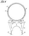
- FIG. 4is a rear sectional view of a first embodiment of the anti-rollover system.
- FIG. 5is a side perspective view of a second embodiment of the anti-rollover system.
- FIG. 6is a side perspective view of a third embodiment of the anti-rollover system.
- FIG. 7is an exploded perspective view of a fourth embodiment of the anti-rollover system.
- FIG. 8is a schematic diagram of a fifth embodiment of anti-rollover system.
- the present inventionis an anti-rollover system for a concrete mixing truck that detects potential rollover conditions and initiates corrective action in an effort to prevent a rollover of the truck during turning maneuvers.
- the anti-rollover systemis comprised of a plurality of sensors and a computer.
- the anti-rollover systemdetects conditions which could lead to a rollover when the concrete mixing truck makes a turn and the system initiates corrective action to prevent a rollover.
- the sensors of the anti-rollover systemmeasure input data representative of the truck's operating conditions, including those conditions which can lead to a potential rollover.
- the datais transmitted as input signals to the computer.
- the input signalsare compared against stored sample data obtained during empirical studies of rollovers.
- the systemdetermines whether the input signals indicate that operating conditions are approaching a threshold indicative of a rollover, and if so, the system initiates corrective action to prevent the truck from rolling over. Corrective action includes stopping rotation of the drum, or in some cases slowing rotation. With mixing trucks including a booster axle system, further corrective action includes releasing pressure from the booster axle to unload the booster axle.
- FIG. 1is a side perspective view of a concrete mixing truck 10 with which the present invention is concerned.
- the mixing truck 10has a cab 12 and a chassis 14 .
- the truck 10typically has three sets of wheels, one set 16 at the cab 12 and a tandem set on the chassis 14 , a front truck set 18 and a rear truck set 20 .
- a drum 22 for holding and mixing concreteis supported by the chassis and attached between a front pedestal 24 and a rear pedestal 26 .
- the front and rear pedestals 24 , 26are connected to a frame 28 of the chassis 14 .
- Rear pedestal 26has a greater height than front pedestal 24 to elevate the rear of the drum 22 .
- a drum motor(shown in FIG. 3 ) controls rotation of the drum 22 to mix the concrete.
- a chute 30is attached to a discharge opening at the rear of the drum 22 , such that the concrete is delivered by the chute 30 from the drum 22 to a work site.
- Some concrete mixing trucksinclude an optional booster axle system 32 which is attached to a rear of the chassis 14 .
- the booster axle system 32helps to distribute and balance the load from the chassis 14 , in particular the drum 22 , by carrying a portion of the load.
- the booster axle 32distributes the gross vehicle weight of the truck over a longer wheelbase.
- the booster axle 32is comprised of a pair of substantially parallel arms 34 , 36 pivotally attached to frame rails at the rear of the truck 10 .
- a set of wheels 38are attached to the rear end of the arms 34 , 36 .
- a booster axle hydraulic cylinder 40is attached between the frame 28 and the arms 34 , 36 to raise and lower the booster axle 32 by hydraulic pressure.
- the booster axle 32is movable between a load position, an unload position, and a raised position. Movement of the booster axle 32 between these three positions is controlled by hydraulic relief valves (shown in FIG. 3 ) and hydraulic cylinder 40 .
- hydraulic cylinder 40exerts a force on the booster axle 32 , pressing the booster axle downward onto the ground.
- the booster axlecarries part of the vehicle weight and thereby reduces the load on the rear axles of the truck.
- hydraulic pressure on cylinder 40is relieved such that wheels 38 of booster axle 32 remain on the ground, however, the booster axle 32 does not carry any load.
- the booster axle 32is raised above the ground and rests against the rear pedestal 26 .
- a hydraulic reservoir (shown in FIG. 3 ) and a hydraulic block 42are located near the front of the chassis 14 between the drum 22 and the cab 12 .
- the hydraulic block 42houses a plurality of relief valves which regulate the hydraulic pressure needed to operate equipment on the truck 10 , including a drum motor (shown in FIG. 3 ) and the booster axle cylinder 40 .
- a pair of drum rollers 44 and 46are attached to the rear pedestal 26 and engage a rear portion of the drum 22 .
- the rollers 44 , 46support drum 22 on the rear pedestal 26 and allow rotation of the drum 22 in the clockwise direction (as viewed from the rear of the truck).
- a pair of sensorsare associated with rollers 44 , 46 (discussed below).
- sensorsmay be located at the rear pedestal 26 , the front pedestal 24 , or at either set of rear wheels of the truck.
- FIG. 2is a schematic view of the rear of the concrete mixing truck 10 showing a concrete load 48 A when drum 22 is not rotating, and load 48 B when drum 22 is rotating.
- the concrete load 48 AWhen the drum 22 is at rest and not rotating, the concrete load 48 A is at a dead load position shown by line A. In the dead load position, the concrete load 48 A is equally dispersed along the bottom of the drum between a left side 50 and a right side 52 of the drum 22 .
- the center of gravity for the concrete load in the dead load positionis at point X. The center of gravity is centered between the rear truck set of tires 20 .
- the drum 22is rotated in the clockwise direction shown by arrow 53 (as seen from the rear of the truck).
- the concrete load 48 Bmoves to a live load position, shown by line B.
- the concrete load 48 Brises, or laterally shifts, up along the left side 50 of the drum.
- the center of gravity when the concrete load is in the live load positionis generally at point Y.
- the concrete load 48 Bis not equally dispersed between the left and right sides 50 , 52 of the drum. The center of gravity rises higher in the drum 22 and shifts to the left of the rear truck set of wheels 20 .
- the speed of drum rotationis based upon the drive transmission speed.
- drum rotation speedincreases.
- the rise of the concrete load on the left side of drum 22is a function of the rotation speed of drum 22 , with a greater rise occurring at higher drum rotation speed.
- the live load position center of gravity Ymoves further away from the lower, centered dead load position center of gravity X.
- Rollover conditionsare especially possible when the concrete mixing truck 10 makes a right turn, because centrifugal force in the opposite direction further increases the concrete load shift up along the left side of the drum.
- Drum rotation and the high, off-centered center of gravitycombined with increased load shifting caused by a right turn, contribute to a potential roll moment which may lead to a rollover.
- a concrete mixing truck 10 beginning a right turn from a substantially stationary positioncan reach a speed of about 12 miles per hour by the end of the turn.
- the drumis rotating and the concrete load is in the live load position with the center of gravity shifted to the left side of the drum.
- the drum rotation speedincreases, which further shifts the concrete load to the left side 50 of the drum 22 .
- the increased lateral load shift caused by the combination of increased drum rotation, the right turn, and the high center of gravity inherent to concrete mixing trucks,contributes to a potential roll moment that can cause the truck 10 to rollover.
- the same problemcan arise when the truck 10 makes a turn at high speeds, such as while navigating a cloverleaf exit ramp or a sharp turn in a roadway.
- the load carried by the booster axle 32may be partially decreased.
- the hydraulic pressure delivered to hydraulic cylinder 40is automatically adjusted to increase the downward force on the booster axle 32 and maintain the desired load on the booster axle 32 .
- the increase of hydraulic pressure to hydraulic cylinder 40 during a vehicle turnmay further contribute to a potential truck rollover.
- FIG. 3is a schematic drawing showing the electrical and hydraulic connections for components of the anti-rollover system of the present invention.
- the electrical connectionsare represented by a dash-dot-dash line and the hydraulic connections are represented by a solid line.
- a first sensor 54 and a second sensor 56are located on the truck 10 to measure data representative of the truck's operating conditions.
- the sensors 54 , 56sense input data representative of parameters relevant to the operation and load of the truck 10 .
- a wide variety of different sensors measuring different parametersmay be used.
- the type of sensors usedmay include load cells, accelerometers, hydraulic pressure sensors, or torque sensors.
- the location of the first and second sensors 54 , 56 shown in FIG. 3does not restrict where the sensors are located in other embodiments of the anti-rollover system. Some embodiments may include a single sensor, and some embodiments may include more than two sensors.
- the sensors 54 , 56measure data representative of current operating conditions of the mixing truck 10 .
- the datais transmitted as an input signal to a computer 58 preferably located in the cab 12 of the truck 10 .
- Each sensoris individually, electrically connected to the computer, such as a central processing unit (CPU) or a programable logic controller (PLC).
- the sensors 54 , 56may optionally be connected to a digital data log 60 which displays the data gathered by the sensors.
- the digital data log 60then transmits the input signals to the computer 58 .
- An example of a digital data log for displaying data from load cellsis included with the ACCUWEIGH9700 System by Precision Loads of Seattle, Wash.
- Sample data indicative of operating conditions which result in a rolloverare stored by the computer 58 .
- the input signals received by the computer 58are analyzed and compared with the sample data to determine whether or not the measured operating conditions are likely to exceed a predetermined threshold indicative of a rollover. If the measured operating conditions indicate the potential for exceeding the predetermined threshold, the computer 58 initiates corrective action to prevent a rollover.
- corrective action to prevent a rolloverinvolves stopping rotation of the drum 22 .
- the computer 58sends a signal to open a drum relief valve 62 (or directional valve), which controls a drum motor 64 .
- the drum relief valve 62dumps hydraulic pressure to drum motor 64 which instantaneously stops rotation of the drum 22 and stops flow of a pump at the drum motor.
- drum rotationis slowed by the anti-rollover system.
- the drum relief valve 62partially opens to decrease hydraulic pressure to drum motor 64 and slow flow through the pump.
- corrective action to prevent a rolloverinvolves unloading the booster axle 32 .
- the load carried by the booster axle 32is partially decreased.
- hydraulic pressure to the cylinder 40is automatically increased to maintain the desired load on the booster axle 32 .
- the increased hydraulic pressure delivered to the booster axle cylindercauses an increased downward force of the booster axle against the ground, which can have a levering effect that may further contribute to a potential rollover by the truck 10 .
- the computer 58sends a signal to the booster relief valve 66 to unload the booster axle 32 .
- the booster relief valve 66opens to instantaneously release pressure in the booster axle cylinder 40 . Pressure in the cylinder 40 is released, thereby putting the booster axle 32 in the unload position and reducing a potential catapult effect by the booster axle 32 .
- the relief valves 62 , 66are located on the hydraulic block 42 .
- additional featuresare included.
- a manual switchis included to override the anti-rollover system.
- a reset featureis included to reset the relief valves in the anti-rollover system, thus, allowing the drum relief valve and the booster relief valve to be re-pressurized such that the drum motor begins rotation and the booster axle moves back to the load position.
- the reset featureis preferably a manual reset switch.
- a visual or auditory alarmis included to notify the driver that rollover conditions exist and corrective actions are being initiated.
- FIG. 4is a rear sectional view of the concrete mixing truck 10 demonstrating the first embodiment of the anti-rollover system of the present invention.
- the first and second sensors 54 , 56are load cell sensors which measure the load of the drum 22 .
- First and second drum rollers 44 , 46are attached to the rear pedestal 26 and engage a rear portion of the drum 22 to allow rotation of the drum 22 in the clockwise direction. As viewed from the rear, the first drum roller 44 is located on the left side of the drum 22 and the second drum roller 46 is located on the right side of the drum 22 .
- the drum rollers 44 , 46are comprised of a base 68 , a pin 70 and a roller 72 .
- the base 68 of the drum roller 44 , 46is connected to the rear pedestal 26 .
- the load cells 54 , 56are placed between the base 68 and the rear pedestal 26 .
- the first load cell 54measures the load on the left side of the drum 22 and the second load cell 56 measures the load on the right side of the drum 22 .
- the load cellis a load pin which replaces the pin 70 connecting the base 68 to the concrete roller 72 .
- the load pinperforms the same function for measuring the concrete load.
- the load distribution across the drum rollers 44 , 46is monitored for conditions of excessive lateral load shifting to one side of the drum 22 as compared with the other side of the drum 22 .
- the load measured by each load cellis approximately equal.
- the load measured by the left load cell 54increases relative to that measured by the right load cell 56 , i.e. the load measured on the left side 50 of the drum 22 is greater than that measured on the right side 52 of the drum 22 .
- the load cells 54 , 56measure the load carried by each drum roller 44 , 46 and the load data is transmitted to the computer 58 .
- the computer 58determines whether the load data represents operating conditions indicative of a rollover. If the load data indicates rollover conditions, the computer 58 initiates the corrective actions discussed above to prevent a rollover.
- FIG. 5is a side perspective view of a second embodiment of the anti-rollover system of the present invention utilizing load cells.
- first and second load cells 74 , 76are located between the rear pedestal 26 and the frame 28 of the chassis 14 .
- the rear pedestal 26includes a left leg 78 and a right leg 80 .
- the frame 28includes a left outer rail 82 and a right outer rail 84 .
- the left leg 78is attached to the left outer rail 82 and the right leg 80 is attached to the right outer rail 84 .
- the first load cell 74is placed between the left leg 78 and the left outer rail 82 and the second load cell 76 is placed between the right leg 80 and the right outer rail 84 .
- the first and second load cells 74 , 76measure the load of the drum 22 on the left and right sides and transmits the data to the computer 58 to determine whether rollover conditions exist as discussed above.
- FIG. 6is a side perspective view of a third embodiment of the present invention anti-rollover system utilizing load cells.
- a first load cell 86 and a second load cellare located at the front pedestal 24 (only the first load cell is shown in FIG. 6 ).
- the front pedestal 24includes a left leg 90 and a right leg 92 .
- the left leg 90extends downward and is attached to the left outer rail 82 of the frame 28 and the right leg 92 extends downward and is attached to the right outer rail 84 of the frame 28 .
- the first load cell 86is placed between a bracket 91 of the left leg 90 and a bracket 93 of the left outer rail 82 and the second load cell (not shown) is placed between a bracket 91 of the right leg 92 and a bracket 93 of the right outer rail 84 .
- both the load cellsmay be placed between the legs 90 , 92 and 82 , 84 outer rails of the frame 28 or only one of the load cells may be placed between brackets connecting the front pedestal 24 to the frame 28 of the truck while the other is placed between the leg and outer rail of the frame.
- the first load cell 86 and the second load cell 88measure the load of the drum 22 on the left and right sides and transmit the data to the computer 58 to determine whether rollover conditions exist as discussed above.
- FIG. 7is a side perspective view of a fourth embodiment of the anti-rollover system of the present invention utilizing load cells.
- first and second load cellsare attached to an axle for the sets of truck tires, preferably the rear chassis set 20 .
- First load cell 94is connected to a left end 96 of the axle and the second load cell is connected to a right end of the axle (only the first load cell is shown in FIG. 7 ).
- Each load cellwraps around the end of the axle.
- the load cellis enclosed in a bushing 98 and the bushing further enclosed in a trunnion stand 100 which is attached to leaf spring 28 that is connected to the frame of the chassis.
- the first and second load cellsmeasure the load of the truck 10 on the right and left sides and transmits the data to the computer 58 to determine whether rollover conditions exist as discussed above.
- FIG. 8is a schematic view of a fifth embodiment of the present invention.
- anti-rollover system 120alternatively comprises one or more sensors 122 A– 122 F associated with the anti-lock and/or electronic brake system electronic control unit (ABS/EBS ECU).
- each of sensors 122 A– 122 Fis an accelerometer, which is capable of monitoring the truck's lateral acceleration.
- Sensors 122 A– 122 Fprovide a signal indicative of the lateral acceleration of the truck to a control system 124 of the truck.
- Control system 124includes an ABS/EBS ECU module 126 that receives the signals from one or more of sensors 122 A– 122 F.
- the signalsare then communicated to and analyzed by an accelerometer analyzer module 128 , which stores data indicative of a lateral acceleration threshold for a rollover condition.
- An accelerometer analyzer module 128stores data indicative of a lateral acceleration threshold for a rollover condition.
- a known control system for sensing and processing lateral acceleration signalsis the RSC control system by Meritor WABCO Vehicle Control Systems of Troy, Mich.
- the accelerometer analyzer module 128communicates with one or more modules, such as engine ECU module 130 , retarder control module 132 , mixer control module 134 , or EBS control module 136 , to initiate a corrective action to prevent a rollover.
- Engine ECU module 130communicates with the truck engine to reduce engine speed.
- the retarder control module 132communicates with a drive line retarder associated with the propeller shaft of the truck. Alternatively, for vehicles equipped with automatic transmission, retarder control module 132 communicates with a retarder in the transmission of the truck to retard torque.
- the mixer control module 134communicates with a hydraulic interface 138 that signals one or both of the booster control 140 and/or the drum control 142 to actuate hydraulic relief valves for the drum motor 144 and/or the booster cylinder 146 in the manner previously described.
- the EBS control module 136communicates with the ABS/EBS ECU module 126 , which activates the truck's brakes to slow the truck and thereby prevent the truck from exceeding a critical lateral acceleration threshold.
- each of the control modules 130 – 136may be performed simultaneously, or sequentially in a predetermined order. If corrective actions are initiated sequentially, a first module signal selected by the control system is communicated to the respective truck component, and signals from the accelerometer are analyzed to determine if further corrective action is required. To the extent the initial corrective action does not result in bringing the lateral acceleration of the truck below the predetermined threshold, subsequent module signals are sequentially selected by the control system and communicated to the respective truck components until the lateral acceleration of the truck is below the predetermined threshold. In a preferred embodiment, the control system initiates corrective action first with the mixer control module 134 .
- the present inventionis a method and apparatus for detecting and preventing a rollover by a concrete mixing truck carrying a concrete load in a drum.
- the apparatusis an anti-rollover system.
- the anti-rollover systemstores data indicative of a rollover condition in a memory device, senses input data representative of operating conditions of the concrete mixing truck, compares the input data and sample data, and initiates corrective action if the input data is indicative of a rollover condition.
- the corrective action taken by the anti-rollover systemincludes any combination of the following: stopping rotation of the drum mixing concrete, slowing rotation of the drum, or releasing pressure from a booster axle system.
- Examples of transmitting means for transmitting the input data the sensorsincludes an electrical connection, a digital data log, or electronic control unit.
- the present invention anti-rollover systemis also employed on a front-discharge mixer where the chute is located forward of the truck's cab (i.e. the drum sits “backward” on a front-discharge truck). The anti-rollover system is equally applicable for left turns.
Landscapes
- Engineering & Computer Science (AREA)
- Mechanical Engineering (AREA)
- Structural Engineering (AREA)
- Transportation (AREA)
- Chemical & Material Sciences (AREA)
- Combustion & Propulsion (AREA)
- Health & Medical Sciences (AREA)
- Public Health (AREA)
- Preparation Of Clay, And Manufacture Of Mixtures Containing Clay Or Cement (AREA)
Abstract
Description
Claims (21)
Priority Applications (1)
| Application Number | Priority Date | Filing Date | Title |
|---|---|---|---|
| US10/391,147US6938716B1 (en) | 2002-03-18 | 2003-03-18 | Concrete mixing truck anti-rollover system |
Applications Claiming Priority (2)
| Application Number | Priority Date | Filing Date | Title |
|---|---|---|---|
| US36523102P | 2002-03-18 | 2002-03-18 | |
| US10/391,147US6938716B1 (en) | 2002-03-18 | 2003-03-18 | Concrete mixing truck anti-rollover system |
Publications (1)
| Publication Number | Publication Date |
|---|---|
| US6938716B1true US6938716B1 (en) | 2005-09-06 |
Family
ID=34890269
Family Applications (1)
| Application Number | Title | Priority Date | Filing Date |
|---|---|---|---|
| US10/391,147Expired - Fee RelatedUS6938716B1 (en) | 2002-03-18 | 2003-03-18 | Concrete mixing truck anti-rollover system |
Country Status (1)
| Country | Link |
|---|---|
| US (1) | US6938716B1 (en) |
Cited By (33)
| Publication number | Priority date | Publication date | Assignee | Title |
|---|---|---|---|---|
| US20040108663A1 (en)* | 2002-12-04 | 2004-06-10 | Jungheinrich Aktiengesellschaft | Four-wheel industrial truck with a swing axle |
| GB2435225A (en)* | 2006-02-16 | 2007-08-22 | Hymix Ltd | A vehicle concrete mixer |
| US20070247964A1 (en)* | 2006-04-25 | 2007-10-25 | Ross Charles E | Arrangement for improving the operational performance of cement mixing truck |
| US20080144424A1 (en)* | 2006-12-19 | 2008-06-19 | Schwing America, Inc. | Automatic drum rotation control concrete transit mixer truck |
| US20080255869A1 (en)* | 2004-02-02 | 2008-10-16 | Young Ayden F | Generating safety report for fleet of vehicles |
| US20090138191A1 (en)* | 2007-11-27 | 2009-05-28 | Elektrobit Automotive Gmbh | Technique for detecting shifted cargo |
| WO2009130351A1 (en)* | 2008-04-22 | 2009-10-29 | Gicalla, S. L. | High-performance concrete mixer truck |
| US20100246313A1 (en)* | 2009-03-25 | 2010-09-30 | Liebherr-Mischtechnik Gmbh | Truck Mixer |
| US20100246314A1 (en)* | 2009-03-25 | 2010-09-30 | Liebherr-Mischtechnik Gmbh | Truck Mixer |
| US20100312438A1 (en)* | 2004-02-13 | 2010-12-09 | Rs Solutions, Llc | Method and System for Calculating and Reporting Slump in Delivery Vehicles |
| US20120004790A1 (en)* | 2007-06-19 | 2012-01-05 | Verifi Llc | Method and System for Calculating and Reporting Slump in Delivery Vehicles |
| US20140015315A1 (en)* | 2011-03-24 | 2014-01-16 | Kayaba Industry Co., Ltd | Mixer drum driving apparatus |
| US8791806B2 (en) | 2011-11-28 | 2014-07-29 | Trimble Navigation Limited | Real-time detection of hazardous driving |
| DE102013012954A1 (en)* | 2013-08-02 | 2015-02-19 | Wabco Gmbh | Method for controlling the driving dynamics of commercial vehicles and vehicle dynamics control device and use of a lateral acceleration sensor |
| US9518870B2 (en) | 2007-06-19 | 2016-12-13 | Verifi Llc | Wireless temperature sensor for concrete delivery vehicle |
| CN106427856A (en)* | 2016-10-21 | 2017-02-22 | 北汽福田汽车股份有限公司 | Concrete mixing truck and rollover preventing method and system thereof |
| US20170080600A1 (en)* | 2015-09-18 | 2017-03-23 | Schwing America, Inc. | Concrete mixer and controls therefor |
| JP2017072556A (en)* | 2015-10-09 | 2017-04-13 | Kyb株式会社 | Mixer truck load weighing device |
| US9718503B2 (en) | 2014-06-06 | 2017-08-01 | Gavin Ursich | Counter-torque rollover prevention architecture |
| EP2772339B1 (en) | 2013-02-28 | 2018-05-16 | Cifa S.P.A. | Concrete mixer truck with safety device |
| CN108422558A (en)* | 2018-01-26 | 2018-08-21 | 北汽福田汽车股份有限公司 | Servo Control method, apparatus and trucd mixer |
| GB2573808A (en)* | 2018-05-18 | 2019-11-20 | Mcphee Bros Blantyre Ltd | System and method to control speed of rotation of a truck-mounted concrete mixer drum |
| US10488172B1 (en) | 2017-10-18 | 2019-11-26 | Zoox, Inc. | Independent control of vehicle wheels |
| CN110757652A (en)* | 2018-07-27 | 2020-02-07 | 比亚迪股份有限公司 | Concrete mixer truck |
| WO2020097619A1 (en)* | 2018-11-09 | 2020-05-14 | Lemon Life Technologies Llc | Smart apparatus for manual mobility assistive devices |
| US10759416B1 (en) | 2017-10-18 | 2020-09-01 | Zoox, Inc. | Independent control of vehicle wheels |
| US10821981B1 (en) | 2017-10-18 | 2020-11-03 | Zoox, Inc. | Independent control of vehicle wheels |
| CN113071435A (en)* | 2021-04-14 | 2021-07-06 | 三一汽车制造有限公司 | Vehicle control method, vehicle, and computer-readable storage medium |
| US11136021B1 (en)* | 2017-10-18 | 2021-10-05 | Zoox, Inc. | Independent control of vehicle wheels |
| US11241923B2 (en) | 2019-03-06 | 2022-02-08 | Aspen Custom Trailers Inc. | Mitigation of booster-induced effects |
| CN116022125A (en)* | 2023-03-23 | 2023-04-28 | 徐州徐工汽车制造有限公司 | Rollover-resistant control method and device, whole vehicle controller and stirring transport vehicle |
| CN116766397A (en)* | 2023-06-19 | 2023-09-19 | 南京航空航天大学 | Side-turning prevention device of concrete mixer truck and control method |
| GB2620936A (en)* | 2022-07-25 | 2024-01-31 | Total Vehicle Solutions Group Ltd | Roll over warning system |
Citations (17)
| Publication number | Priority date | Publication date | Assignee | Title |
|---|---|---|---|---|
| US3161418A (en)* | 1963-03-04 | 1964-12-15 | Challenge Cook Bros Inc | Vehicular wheel assembly |
| US3773304A (en)* | 1972-04-17 | 1973-11-20 | London Concrete Mach | Control for vehicular concrete mixer |
| US4206829A (en)* | 1976-12-27 | 1980-06-10 | Towmotor Corporation | Control system for lift trucks or the like |
| US4261616A (en)* | 1978-12-18 | 1981-04-14 | Beegle William I | Apparatus for preventing the tipping of dump vehicles |
| JPS5992273A (en)* | 1982-11-15 | 1984-05-28 | Kubota Ltd | work vehicle |
| US4585356A (en)* | 1983-04-05 | 1986-04-29 | Ingrid Hudelmaier | Concrete mixer truck |
| US4712807A (en) | 1985-02-06 | 1987-12-15 | Toyota Jidosha Kabushiki Kaisha | Vehicle active suspension system incorporating acceleration detecting means |
| US5032821A (en) | 1989-05-12 | 1991-07-16 | Domanico Edward J | Motor vehicle stability monitoring and alarm system and method |
| JPH04191179A (en)* | 1990-11-26 | 1992-07-09 | Hino Motors Ltd | Device for indicating vehicle roll-over limit |
| US5149126A (en)* | 1990-03-05 | 1992-09-22 | Rexworks, Inc. | Truck mixer mounting frame |
| US5383680A (en)* | 1992-12-21 | 1995-01-24 | Cadillac Gage Textron Inc. | Anti-roll system for wheeled vehicles |
| US5825284A (en) | 1996-12-10 | 1998-10-20 | Rollover Operations, Llc | System and method for the detection of vehicle rollover conditions |
| US5897123A (en)* | 1997-09-05 | 1999-04-27 | Oshkosh Truck Corporation | Tag axle pivot |
| US6209887B1 (en) | 1999-04-05 | 2001-04-03 | Meritor Heavy Vehicle Systems, Llc | Microprocessor controlled vehicle suspension |
| US6225894B1 (en) | 1998-09-24 | 2001-05-01 | Meritor Heavy Vehicle Systems, Llc | Roll-over detector for vehicles |
| US6363331B1 (en) | 1998-12-09 | 2002-03-26 | Meritor Heavy Vehicle Systems, Llc | Weight distribution monitor |
| US6452487B1 (en)* | 2000-02-14 | 2002-09-17 | Stanley Krupinski | System and method for warning of a tip over condition in a tractor trailer or tanker |
- 2003
- 2003-03-18USUS10/391,147patent/US6938716B1/ennot_activeExpired - Fee Related
Patent Citations (17)
| Publication number | Priority date | Publication date | Assignee | Title |
|---|---|---|---|---|
| US3161418A (en)* | 1963-03-04 | 1964-12-15 | Challenge Cook Bros Inc | Vehicular wheel assembly |
| US3773304A (en)* | 1972-04-17 | 1973-11-20 | London Concrete Mach | Control for vehicular concrete mixer |
| US4206829A (en)* | 1976-12-27 | 1980-06-10 | Towmotor Corporation | Control system for lift trucks or the like |
| US4261616A (en)* | 1978-12-18 | 1981-04-14 | Beegle William I | Apparatus for preventing the tipping of dump vehicles |
| JPS5992273A (en)* | 1982-11-15 | 1984-05-28 | Kubota Ltd | work vehicle |
| US4585356A (en)* | 1983-04-05 | 1986-04-29 | Ingrid Hudelmaier | Concrete mixer truck |
| US4712807A (en) | 1985-02-06 | 1987-12-15 | Toyota Jidosha Kabushiki Kaisha | Vehicle active suspension system incorporating acceleration detecting means |
| US5032821A (en) | 1989-05-12 | 1991-07-16 | Domanico Edward J | Motor vehicle stability monitoring and alarm system and method |
| US5149126A (en)* | 1990-03-05 | 1992-09-22 | Rexworks, Inc. | Truck mixer mounting frame |
| JPH04191179A (en)* | 1990-11-26 | 1992-07-09 | Hino Motors Ltd | Device for indicating vehicle roll-over limit |
| US5383680A (en)* | 1992-12-21 | 1995-01-24 | Cadillac Gage Textron Inc. | Anti-roll system for wheeled vehicles |
| US5825284A (en) | 1996-12-10 | 1998-10-20 | Rollover Operations, Llc | System and method for the detection of vehicle rollover conditions |
| US5897123A (en)* | 1997-09-05 | 1999-04-27 | Oshkosh Truck Corporation | Tag axle pivot |
| US6225894B1 (en) | 1998-09-24 | 2001-05-01 | Meritor Heavy Vehicle Systems, Llc | Roll-over detector for vehicles |
| US6363331B1 (en) | 1998-12-09 | 2002-03-26 | Meritor Heavy Vehicle Systems, Llc | Weight distribution monitor |
| US6209887B1 (en) | 1999-04-05 | 2001-04-03 | Meritor Heavy Vehicle Systems, Llc | Microprocessor controlled vehicle suspension |
| US6452487B1 (en)* | 2000-02-14 | 2002-09-17 | Stanley Krupinski | System and method for warning of a tip over condition in a tractor trailer or tanker |
Non-Patent Citations (1)
| Title |
|---|
| Arvin Meritor article from www.arvinmeritor.com, published prior to Mar. 18, 2003. |
Cited By (51)
| Publication number | Priority date | Publication date | Assignee | Title |
|---|---|---|---|---|
| US7137473B2 (en)* | 2002-12-04 | 2006-11-21 | Jungheinrich Aktiengesellschaft | Four-wheel industrial truck with a swing axle |
| US20040108663A1 (en)* | 2002-12-04 | 2004-06-10 | Jungheinrich Aktiengesellschaft | Four-wheel industrial truck with a swing axle |
| US20080255869A1 (en)* | 2004-02-02 | 2008-10-16 | Young Ayden F | Generating safety report for fleet of vehicles |
| US8727604B2 (en) | 2004-02-13 | 2014-05-20 | Verifi Llc | Method and system for calculating and reporting slump in delivery vehicles |
| US20100312406A1 (en)* | 2004-02-13 | 2010-12-09 | Rs Solutions, Llc | Method and System for Calculating and Reporting Slump in Delivery Vehicles |
| US20100312438A1 (en)* | 2004-02-13 | 2010-12-09 | Rs Solutions, Llc | Method and System for Calculating and Reporting Slump in Delivery Vehicles |
| GB2435225A (en)* | 2006-02-16 | 2007-08-22 | Hymix Ltd | A vehicle concrete mixer |
| EP1820692A1 (en)* | 2006-02-16 | 2007-08-22 | Hymix Limited | A vehicle having a drum |
| US7740396B2 (en) | 2006-04-25 | 2010-06-22 | Bendix Commercial Vehicle Systems Llc | Arrangement for improving the operational performance of cement mixing truck |
| US20070247964A1 (en)* | 2006-04-25 | 2007-10-25 | Ross Charles E | Arrangement for improving the operational performance of cement mixing truck |
| WO2007123593A1 (en)* | 2006-04-25 | 2007-11-01 | Bendix Commercial Vehicle Systems Llc | An arrangement for improving the operational performance of cement mixing truck |
| AU2007241157B2 (en)* | 2006-04-25 | 2013-05-16 | Bendix Commercial Vehicle Systems Llc | Arrangement for improving the operational performance of cement mixing truck |
| US20080144424A1 (en)* | 2006-12-19 | 2008-06-19 | Schwing America, Inc. | Automatic drum rotation control concrete transit mixer truck |
| US7722243B2 (en)* | 2006-12-19 | 2010-05-25 | Schwing America, Inc. | Automatic drum rotation control concrete transit mixer truck |
| US20120004790A1 (en)* | 2007-06-19 | 2012-01-05 | Verifi Llc | Method and System for Calculating and Reporting Slump in Delivery Vehicles |
| US9518870B2 (en) | 2007-06-19 | 2016-12-13 | Verifi Llc | Wireless temperature sensor for concrete delivery vehicle |
| US8746954B2 (en) | 2007-06-19 | 2014-06-10 | Verifi Llc | Method and system for calculating and reporting slump in delivery vehicles |
| US20090138191A1 (en)* | 2007-11-27 | 2009-05-28 | Elektrobit Automotive Gmbh | Technique for detecting shifted cargo |
| US8150613B2 (en)* | 2007-11-27 | 2012-04-03 | Elektrobit Automotive Gmbh | Technique for detecting shifted cargo |
| ES2335462B1 (en)* | 2008-04-22 | 2011-01-03 | Gicalla, S.L. | HIGH PERFORMANCE CONCRETE TRUCK. |
| WO2009130351A1 (en)* | 2008-04-22 | 2009-10-29 | Gicalla, S. L. | High-performance concrete mixer truck |
| ES2335462A1 (en)* | 2008-04-22 | 2010-03-26 | Gicalla, S.L. | High-performance concrete mixer truck |
| US20100246313A1 (en)* | 2009-03-25 | 2010-09-30 | Liebherr-Mischtechnik Gmbh | Truck Mixer |
| US20100246314A1 (en)* | 2009-03-25 | 2010-09-30 | Liebherr-Mischtechnik Gmbh | Truck Mixer |
| US20140015315A1 (en)* | 2011-03-24 | 2014-01-16 | Kayaba Industry Co., Ltd | Mixer drum driving apparatus |
| US9694683B2 (en)* | 2011-03-24 | 2017-07-04 | Kyb Corporation | Mixer drum driving apparatus |
| US8791806B2 (en) | 2011-11-28 | 2014-07-29 | Trimble Navigation Limited | Real-time detection of hazardous driving |
| EP2772339B1 (en) | 2013-02-28 | 2018-05-16 | Cifa S.P.A. | Concrete mixer truck with safety device |
| DE102013012954A1 (en)* | 2013-08-02 | 2015-02-19 | Wabco Gmbh | Method for controlling the driving dynamics of commercial vehicles and vehicle dynamics control device and use of a lateral acceleration sensor |
| US9718503B2 (en) | 2014-06-06 | 2017-08-01 | Gavin Ursich | Counter-torque rollover prevention architecture |
| US10744676B2 (en)* | 2015-09-18 | 2020-08-18 | Schwing America, Inc. | Concrete mixer and controls therefor for controlling drum rotation |
| US20170080600A1 (en)* | 2015-09-18 | 2017-03-23 | Schwing America, Inc. | Concrete mixer and controls therefor |
| JP2017072556A (en)* | 2015-10-09 | 2017-04-13 | Kyb株式会社 | Mixer truck load weighing device |
| WO2017061613A1 (en)* | 2015-10-09 | 2017-04-13 | Kyb株式会社 | Load weight measuring device for concrete mixer vehicle |
| CN106427856A (en)* | 2016-10-21 | 2017-02-22 | 北汽福田汽车股份有限公司 | Concrete mixing truck and rollover preventing method and system thereof |
| US10488172B1 (en) | 2017-10-18 | 2019-11-26 | Zoox, Inc. | Independent control of vehicle wheels |
| US11136021B1 (en)* | 2017-10-18 | 2021-10-05 | Zoox, Inc. | Independent control of vehicle wheels |
| US10759416B1 (en) | 2017-10-18 | 2020-09-01 | Zoox, Inc. | Independent control of vehicle wheels |
| US10821981B1 (en) | 2017-10-18 | 2020-11-03 | Zoox, Inc. | Independent control of vehicle wheels |
| US12258004B2 (en) | 2017-10-18 | 2025-03-25 | Zoox, Inc. | Independent control of vehicle wheels |
| CN108422558B (en)* | 2018-01-26 | 2019-10-22 | 北汽福田汽车股份有限公司 | Servo Control method, apparatus and mixer truck |
| CN108422558A (en)* | 2018-01-26 | 2018-08-21 | 北汽福田汽车股份有限公司 | Servo Control method, apparatus and trucd mixer |
| GB2573808A (en)* | 2018-05-18 | 2019-11-20 | Mcphee Bros Blantyre Ltd | System and method to control speed of rotation of a truck-mounted concrete mixer drum |
| CN110757652A (en)* | 2018-07-27 | 2020-02-07 | 比亚迪股份有限公司 | Concrete mixer truck |
| WO2020097619A1 (en)* | 2018-11-09 | 2020-05-14 | Lemon Life Technologies Llc | Smart apparatus for manual mobility assistive devices |
| US11241923B2 (en) | 2019-03-06 | 2022-02-08 | Aspen Custom Trailers Inc. | Mitigation of booster-induced effects |
| CN113071435A (en)* | 2021-04-14 | 2021-07-06 | 三一汽车制造有限公司 | Vehicle control method, vehicle, and computer-readable storage medium |
| GB2620936A (en)* | 2022-07-25 | 2024-01-31 | Total Vehicle Solutions Group Ltd | Roll over warning system |
| CN116022125A (en)* | 2023-03-23 | 2023-04-28 | 徐州徐工汽车制造有限公司 | Rollover-resistant control method and device, whole vehicle controller and stirring transport vehicle |
| CN116022125B (en)* | 2023-03-23 | 2023-08-08 | 徐州徐工汽车制造有限公司 | Rollover-resistant control method and device, whole vehicle controller and stirring transport vehicle |
| CN116766397A (en)* | 2023-06-19 | 2023-09-19 | 南京航空航天大学 | Side-turning prevention device of concrete mixer truck and control method |
Similar Documents
| Publication | Publication Date | Title |
|---|---|---|
| US6938716B1 (en) | Concrete mixing truck anti-rollover system | |
| CN110775046B (en) | Vehicle rollover prevention control system and rollover prevention control method | |
| US6741922B2 (en) | Antilock braking system based roll over prevention | |
| JP2593336B2 (en) | Brake control device | |
| CN114286760B (en) | Motor vehicle with lifting bridge and method of operating the same | |
| JP2673358B2 (en) | Brake control device for tractor / trailer | |
| JPH0585330A (en) | Trailer brake control device and control method | |
| MX2014003905A (en) | A towing vehicle controller providing brake control to a towed vehicle and method. | |
| KR20000070352A (en) | Method and Device for detecting motor vehicle tilt | |
| MXPA04012613A (en) | Roll stability control system. | |
| EP0288866B1 (en) | Tractor-trailer brake control system | |
| JP2001180468A (en) | Method of preventing turnover of vehicle | |
| US6378957B1 (en) | Arrangement for controlling vehicle braking | |
| JP2000512952A (en) | Vehicle equipment | |
| AU2007248893A1 (en) | Vehicle stability control system with multiple sensitivities | |
| CN102753410B (en) | Method for operating a brake-slip regulating means of a brake system of a vehicle | |
| US9840236B2 (en) | Method of, and apparatus for, operating a vehicle | |
| US8112211B2 (en) | Method and device for hydrostatically braking a vehicle | |
| FR2968602A1 (en) | DEVICE FOR REPORTING A LOADING MALFUNCTION OF A TILTING BENCH | |
| JP3992936B2 (en) | Vehicle rollover prevention device | |
| USRE33697E (en) | Tractor-trailer brake control system | |
| JPH04159182A (en) | Method and device for controlling trailer anchoring brake | |
| EP1631481A1 (en) | Method and arrangement for controlling brakes in a vehicle or a combination of vehicles | |
| EP2294370B1 (en) | Method and device for controlling a function of a vehicle. | |
| CN214874098U (en) | Vehicle rollover prevention control system |
Legal Events
| Date | Code | Title | Description |
|---|---|---|---|
| AS | Assignment | Owner name:SCHWING AMERICA, INC., MINNESOTA Free format text:ASSIGNMENT OF ASSIGNORS INTEREST;ASSIGNOR:EULL, THOMAS E.;REEL/FRAME:013889/0191 Effective date:20030317 | |
| REMI | Maintenance fee reminder mailed | ||
| AS | Assignment | Owner name:WELLS FARGO BANK, NATIONAL ASSOCIATION, MINNESOTA Free format text:SECURITY AGREEMENT;ASSIGNOR:SCHWING AMERICA, INC.;REEL/FRAME:022694/0626 Effective date:20090215 Owner name:WELLS FARGO BANK, NATIONAL ASSOCIATION,MINNESOTA Free format text:SECURITY AGREEMENT;ASSIGNOR:SCHWING AMERICA, INC.;REEL/FRAME:022694/0626 Effective date:20090215 | |
| REIN | Reinstatement after maintenance fee payment confirmed | ||
| FP | Lapsed due to failure to pay maintenance fee | Effective date:20090906 | |
| FEPP | Fee payment procedure | Free format text:PETITION RELATED TO MAINTENANCE FEES FILED (ORIGINAL EVENT CODE: PMFP); ENTITY STATUS OF PATENT OWNER: LARGE ENTITY | |
| FEPP | Fee payment procedure | Free format text:PETITION RELATED TO MAINTENANCE FEES GRANTED (ORIGINAL EVENT CODE: PMFG); ENTITY STATUS OF PATENT OWNER: LARGE ENTITY | |
| FPAY | Fee payment | Year of fee payment:4 | |
| SULP | Surcharge for late payment | ||
| AS | Assignment | Owner name:WELLS FARGO BANK, NATIONAL ASSOCIATION AS ADMINIST Free format text:RELEASE AND TERMINATION AGREEMENT;ASSIGNOR:SCHWING AMERICA, INC.;REEL/FRAME:024697/0254 Effective date:20100714 | |
| AS | Assignment | Owner name:DEUTSCHE BANK AG, STUTTGART, AS SECURITY TRUSTEE, Free format text:SECURITY AGREEMENT SUPPLEMENT;ASSIGNOR:SCHWING AMERICA, INC.;REEL/FRAME:024733/0085 Effective date:20100714 | |
| PRDP | Patent reinstated due to the acceptance of a late maintenance fee | Effective date:20100816 | |
| REMI | Maintenance fee reminder mailed | ||
| LAPS | Lapse for failure to pay maintenance fees | ||
| STCH | Information on status: patent discontinuation | Free format text:PATENT EXPIRED DUE TO NONPAYMENT OF MAINTENANCE FEES UNDER 37 CFR 1.362 | |
| FP | Lapsed due to failure to pay maintenance fee | Effective date:20130906 | |
| AS | Assignment | Owner name:SCHWING AMERICA, INC., MINNESOTA Free format text:RELEASE BY SECURED PARTY;ASSIGNOR:DEUTSCHE BANK AG, STUTTGART, GERMANY;REEL/FRAME:055133/0755 Effective date:20210203 |