US6938711B2 - Freestanding self-propelled device for moving objects - Google Patents
Freestanding self-propelled device for moving objectsDownload PDFInfo
- Publication number
- US6938711B2 US6938711B2US10/703,056US70305603AUS6938711B2US 6938711 B2US6938711 B2US 6938711B2US 70305603 AUS70305603 AUS 70305603AUS 6938711 B2US6938711 B2US 6938711B2
- Authority
- US
- United States
- Prior art keywords
- propelled device
- self
- chassis
- drive wheel
- frame portions
- Prior art date
- Legal status (The legal status is an assumption and is not a legal conclusion. Google has not performed a legal analysis and makes no representation as to the accuracy of the status listed.)
- Expired - Fee Related, expires
Links
- 210000003141lower extremityAnatomy0.000claimsdescription8
- 235000004443Ricinus communisNutrition0.000claimsdescription2
- 210000001364upper extremityAnatomy0.000claimsdescription2
- 230000002441reversible effectEffects0.000description4
- 230000008901benefitEffects0.000description3
- 230000006835compressionEffects0.000description2
- 238000007906compressionMethods0.000description2
- 238000010276constructionMethods0.000description2
- 210000003813thumbAnatomy0.000description2
- 238000002604ultrasonographyMethods0.000description2
- 210000000707wristAnatomy0.000description2
- 208000027418Wounds and injuryDiseases0.000description1
- 230000006378damageEffects0.000description1
- 230000000881depressing effectEffects0.000description1
- 210000003414extremityAnatomy0.000description1
- 230000002401inhibitory effectEffects0.000description1
- 208000014674injuryDiseases0.000description1
Images
Classifications
- B—PERFORMING OPERATIONS; TRANSPORTING
- B62—LAND VEHICLES FOR TRAVELLING OTHERWISE THAN ON RAILS
- B62D—MOTOR VEHICLES; TRAILERS
- B62D51/00—Motor vehicles characterised by the driver not being seated
- B62D51/04—Motor vehicles characterised by the driver not being seated the driver walking
- A—HUMAN NECESSITIES
- A61—MEDICAL OR VETERINARY SCIENCE; HYGIENE
- A61G—TRANSPORT, PERSONAL CONVEYANCES, OR ACCOMMODATION SPECIALLY ADAPTED FOR PATIENTS OR DISABLED PERSONS; OPERATING TABLES OR CHAIRS; CHAIRS FOR DENTISTRY; FUNERAL DEVICES
- A61G5/00—Chairs or personal conveyances specially adapted for patients or disabled persons, e.g. wheelchairs
- A61G5/04—Chairs or personal conveyances specially adapted for patients or disabled persons, e.g. wheelchairs motor-driven
- A61G5/047—Chairs or personal conveyances specially adapted for patients or disabled persons, e.g. wheelchairs motor-driven by a modular detachable drive system
Definitions
- the present inventiongenerally relates to devices for moving objects, such as wheeled carts, beds, equipment, etc., including those used in medical, food service and industrial facilities. More particularly, this invention relates to a freestanding device that uses a single battery-powered drive wheel and can be attached to and used to move an object without significant physical effort by the operator.
- the present inventionprovides a freestanding self-propelled device for moving objects, such as wheeled objects.
- the self-propelled devicehas a single drive wheel and can be attached to and used to move carts, beds or most any other equipment currently pushed or pulled by human operators.
- the devicecan be operated without significant physical effort by the operator, thereby eliminating back, shoulder and wrist strain when attempting to move large objects.
- the self-propelled deviceincludes a chassis having lower frame portions and upright frame portions that extend upward from the lower frame portions.
- An apparatusis coupled to the upright frame portions for gripping a wheeled object.
- a single drive wheelis centrally located between the lateral ends of the chassis and coupled to the chassis so as to be rotatable about a horizontal axis and pivotable about a substantially vertical axis.
- An electrical motoris coupled to the drive wheel to cause rotation of the drive wheel, and at least one battery is coupled to the motor for delivering electrical power to the motor.
- a tilleris pivotably coupled to the drive wheel to enable pivoting of the drive wheel about its vertical axis. The tiller comprises controls for operating the motor and the drive wheel.
- the drive wheelis centrally located between first and second sets of support wheels coupled to the lower frame portion of the chassis.
- the drive wheel and the support wheelsresult in the self-propelled device being freestanding.
- the drive wheelprojects below the first and second sets of support wheels so that the self-propelled device is supported by the drive wheel and by only one of the sets of support wheels at any given time, thereby establishing a three-point contact with the surface supporting the self-propelled device.
- the deviceis further equipped with a third set of support wheels mounted to the chassis and extending aft from the aft end of the chassis, so as to inhibit tipping of the self-propelled device in an aft direction thereof.
- a significant advantage of this inventionis that it can be attached to an object to be moved, such as a cart, bed, wheelchair, machine, or other equipment that may be equipped with wheels, and thereafter an operator can walk behind the device while operating the device through the controls on the tiller to move and maneuver the object.
- the deviceis both stable and highly maneuverable as a result of the arrangement of wheels supporting the chassis.
- the self-propelled device of this inventionis capable of moving large objects while significantly reducing the risk of stress to backs, shoulders, or wrists of workers who would otherwise be required to manually move such objects.
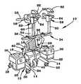
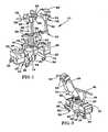
- FIGS. 1 and 2are front and rear perspective views of a self-propelled device in accordance with a preferred embodiment of this invention.
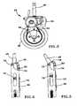
- FIG. 3is a side view of a drive wheel carriage of the device of FIGS. 1 and 2 .
- FIGS. 4 and 5are side views showing articulation of a tiller-drive fork assembly of the device of FIGS. 1 and 2 .
- FIGS. 1 and 2show a freestanding self-propelled moving device 10 in accordance with a preferred embodiment of this invention.
- the device 10comprises a chassis 12 that has a pair of lower frame members 14 that extend in the fore and aft directions of the device 10 .
- a pair of hollow (e.g., tubular) upright frame members 16are individually attached to the lower frame members 14 , and a laterally-extending cross bar 18 interconnects midportions of the upright frame members 16 .
- Each upright frame member 16has an upper extremity 20 that projects above its corresponding lower frame member 14 , and a lower extremity 22 that projects below its lower frame member 14 .
- the upright frame members 16are attached near their lower extremities 22 to their respective lower frame members 14 toward the aft end of the device 10 . Furthermore, each upright frame member 16 is inclined in the fore direction of the device 10 , preferably at an angle of about 64 degrees from horizontal, so that the lower extremity 22 of each upright frame member 16 projects in the aft direction of the device 10 .
- the lower frame members 14are spaced apart toward the lateral extremities of the chassis 12 so as to define a space 24 therebetween.
- the lower frame members 14When viewed from above, the lower frame members 14 have an L-shape, with a first leg of the L oriented laterally at the aft end of the device 10 .
- the second leg of the Lis oriented fore and aft, with the aft end of the second leg attached to the first leg.
- a pivoting caster wheel 26is mounted to the laterally outward end of each first leg of the lower frame members 14
- another pivoting caster wheel 26is mounted to the fore end of each second leg of the lower frame members 14 .
- the chassis 12is configured to have a quadrangle of four points of support defined by the wheels 26 , with the wheels 26 at the fore ends of the lower frame members being closer together than the wheels 26 at the laterally outward ends of the lower frame members 14 .
- a tray 28is mounted to each lower frame member 14 for supporting a battery housing 30 (and a battery therein) at each of the lateral ends of the chassis 12 .
- a drag wheel 32is shown mounted to each lower extremity 22 of the upright frame members 16 of the chassis 12 . Because the upright frame members 16 are inclined relative to the lower frame members 14 , the drag wheels 32 extend in the aft direction from the aft end of the chassis 12 and at an angle (e.g., about 64 degrees) from horizontal. As will be discussed further, the drag wheels 32 do not normally contact the surface on which the device 10 is supported, but come into contact with the surface if the device 10 is tipped in the aft direction, thereby inhibiting tipping of the device 10 .
- a T-bar 34is shown coupled to the upright frame members 16 of the chassis 12 .
- the T-bar 34comprises a pair of legs 36 slidably received within the upright frame members 16 , and a laterally-extending beam 38 between and interconnecting the legs 36 .
- a knob 40is threaded into each upright frame member 16 for engagement with the legs 36 to selectively permit or prevent movement of the legs 36 within the upright frame members 16 . Because of the telescoping connection between the upright frame members 16 and the T-bar 34 , the beam 38 of the T-bar 34 can be adjusted to various heights corresponding to, for example, a patient cart, bed, ultrasound machine, etc., which can be attached to the beam 38 as discussed below.
- various other structurescould be mounted to the device 10 with the telescoping connections provided by the upright frame members 16 .
- a fork lift equipped with a suitable lifting mechanismcould be constructed with legs sized to telescope within the upright frame members 16 .
- FIG. 3is an isolated side view of the drive wheel carriage 42 , and shows the carriage 42 as comprising a fork 44 and a drive wheel 46 rotatably mounted to the fork 44 .
- the fork 44is equipped with a post 48 for pivotably mounting the wheel carriage 42 to the cross bar 18 of the chassis 12 .
- the post 48is preferably oriented so that the wheel carriage 42 , including the fork 44 and wheel 46 , has a substantially vertical axis about which the wheel 46 is able to pivot.
- the wheel 46is preferably able to pivot a full 180 degrees, with both pivot limits preferably coinciding with the horizontal axis of rotation of the wheel 46 being oriented in the fore-aft direction.
- the carriage 42is preferably equipped with a suitable locking feature (not shown) that prevents the wheel 46 from pivoting about its vertical axis.
- FIG. 3also shows an electrical motor 50 mounted to the fork 44 and coupled to the drive wheel through a chain 52 . Power for the motor 50 is provided by the batteries 30 supported on the lower frame members 14 of the chassis 12 .
- the motor 50is preferably a 24-volt, reversible direct current electric motor. While the motor 50 is shown as coupled to the drive wheel 46 with a chain 52 , a drive belt or other suitable means could be used.
- the drive wheel 46is much larger than the caster wheels 26 . Furthermore, the drive wheel 46 is centrally located between lateral pairs of the caster wheels 26 , and projects below the caster wheels 26 so that at any given time the self-propelled device 10 is supported by the drive wheel 46 and by only one of each pair of castor wheels 26 (i.e., the fore pair of wheels 26 located at the fore end of the device 10 , or the aft pair of wheels 26 located at the aft end of the device 10 ). As such, together the wheels 26 and 46 provide the device 10 with a three-point contact with the surface supporting the device 10 .
- the device 10is able to stand unattended when it is not connected to a cart, bed or other object. Because the caster wheels 26 are positioned and arranged so that only two (either the fore or aft pair) are engaged at any one time, maximum downward pressure is exerted on the drive wheel 46 for traction. Furthermore, forward thrust is brought to bear on the drive wheel 46 and the aft caster wheels 26 , while reverse thrust is brought to bear on the drive wheel 46 and the two fore caster wheels 26 .
- Stability and safetyare enhanced by the presence of the drag wheels 32 at the lower extremities 22 of the upright frame members 16 , particularly during forward operation when high loads and/or certain maneuvers can cause the device 10 to tilt backwards, thereby bringing the drag wheels 32 into contact with the surface on which the device 10 is supported.
- a tiller 54that is pivotably coupled to the fork 44 .
- the device 10can be steered by causing the drive wheel 46 to pivot about its vertical axis.
- the tiller 54is preferably capable of being pivoted about 110 degrees relative to the fork 44 , thereby adapting to the height of the operator.
- the tiller 54is equipped at its upper end with a handlebar 56 , on or near which controls are mounted for controlling the operation of the device 10 , including its drive wheel 46 and motor 50 .
- current to the motor 50is preferably controlled by a potentiometer activated by thumb switches 58 (one of which is visible in FIGS. 1 and 2 ) located adjacent the handlebar 56 .
- a computer(not shown) can be housed within one of the covers housing the batteries 30 or within the tiller 54 , through which the input from the switches 58 can be used to control the motor 50 .
- the computerprovides electronic braking and fully adjustable ramp of speed and power curves in both forward and reverse directions.
- FIGS. 4 and 5show the manner in which the tiller 54 is preferably connected to the fork 44 of the wheel carriage 42 .
- the interior of the tiller 54is shown in FIGS. 4 and 5 as comprising a frame 66 that is pivotably attached with a hinge 70 to a flange 78 on the fork 44 .
- a pair of friction plates 72 and 74are mounted to the frame 66 .
- a first plate 72is secured to the frame 66
- the second plate 74is coupled to the first plate 72 under a compression load induced by a fastener 76 .
- the compression loadpermits smooth movement of the second plate 74 relative to the first plate 72 .
- One end of the second plate 74is coupled with a second hinge 80 to the flange 78 of the post 48 .
- pivoting of the post 48 relative to the frame 66 of the tiller 54must overcome the frictional resistance of the plates 72 and 74 .
- a gripping tool 59is attached to the horizontal beam 38 of the T-bar 34 .
- the gripping tool 59is shown comprising a set of upper and lower jaws 62 and 64 mounted to an arm 60 adjustably mounted to the beam 38 .
- the upper jaw 62is immovably mounted to the arm 60 while the lower jaw 64 is movably mounted to the arm 60 for movement relative to the upper jaw 62 .
- engagement of an object with the tool 59 by upward movement of the lower jaw 64results in a portion of the object's weight being transferred to the drive wheel 46 , thereby improving traction of the drive wheel 46 and stability of the device 10 .
- Various other types of fastening and gripping attachmentscan be connected to the T-bar 34 to bind the device 10 to an object intended to be moved.
- attachment to wheelchairscan be achieved by a handlebar side clamp or draw hasp attached to the beam 38 of the T-bar 34 .
- the device 10can also be attached to equipment such as an ultrasound machine with quick release clamps, again attached to the beam 38 of the T-bar 34 .
- the operatoractivates the self-propelled device 10 to move forward or reverse by depressing the appropriate thumb switch 58 on the handlebar 56 of the tiller 54 , and steers the direction of the device 10 by rotating the tiller 54 with the handlebar 56 .
- the device 10is both stable and highly maneuverable under significant loads as a result of the arrangement of the drive wheel 46 , caster wheels 26 , and drag wheel 32 supporting the chassis 12 .
Landscapes
- Engineering & Computer Science (AREA)
- Chemical & Material Sciences (AREA)
- Combustion & Propulsion (AREA)
- Transportation (AREA)
- Mechanical Engineering (AREA)
- Agricultural Machines (AREA)
- Handcart (AREA)
Abstract
Description
Claims (18)
Priority Applications (1)
| Application Number | Priority Date | Filing Date | Title |
|---|---|---|---|
| US10/703,056US6938711B2 (en) | 2002-11-06 | 2003-11-06 | Freestanding self-propelled device for moving objects |
Applications Claiming Priority (2)
| Application Number | Priority Date | Filing Date | Title |
|---|---|---|---|
| US42374902P | 2002-11-06 | 2002-11-06 | |
| US10/703,056US6938711B2 (en) | 2002-11-06 | 2003-11-06 | Freestanding self-propelled device for moving objects |
Publications (2)
| Publication Number | Publication Date |
|---|---|
| US20040134692A1 US20040134692A1 (en) | 2004-07-15 |
| US6938711B2true US6938711B2 (en) | 2005-09-06 |
Family
ID=32717512
Family Applications (1)
| Application Number | Title | Priority Date | Filing Date |
|---|---|---|---|
| US10/703,056Expired - Fee RelatedUS6938711B2 (en) | 2002-11-06 | 2003-11-06 | Freestanding self-propelled device for moving objects |
Country Status (1)
| Country | Link |
|---|---|
| US (1) | US6938711B2 (en) |
Cited By (12)
| Publication number | Priority date | Publication date | Assignee | Title |
|---|---|---|---|---|
| US20050279537A1 (en)* | 2004-06-18 | 2005-12-22 | Ken Nguyen | Motorized vehicle for maneuvering another wheeled apparatus |
| US20060254834A1 (en)* | 2005-05-11 | 2006-11-16 | Alfred Dassler | Method and apparatus for moving a bed |
| US20080066974A1 (en)* | 2006-09-14 | 2008-03-20 | Pearlman Jonathan L | Personal vehicle |
| US20090065272A1 (en)* | 2007-09-06 | 2009-03-12 | Martin James F | Rolltainer transporter |
| US20090200092A1 (en)* | 2006-01-05 | 2009-08-13 | Intuitive Surgical, Inc. | Methods of steering heavy mobile medical equipment |
| US20120090904A1 (en)* | 2006-07-12 | 2012-04-19 | Bezile Randall J | Wheelchair tow device |
| US8684113B1 (en)* | 2012-02-28 | 2014-04-01 | Gregory Edward Laconis | Attachable, powered drive apparatus for wheelchairs |
| CN104108411A (en)* | 2013-04-22 | 2014-10-22 | Jlg工业公司 | Self-propel Accessory |
| US20150000989A1 (en)* | 2013-06-28 | 2015-01-01 | Sunpex Technology Co., Ltd. | Electric moving device for moving patient beds |
| US9326901B2 (en)* | 2013-06-04 | 2016-05-03 | Giovanni CONTE | Removable motor power device for wheelchairs of disabled users |
| US9333979B2 (en) | 2014-02-13 | 2016-05-10 | Avi Iron Solutions Ltd. | Auxiliary pusher device |
| US12208038B2 (en) | 2012-09-18 | 2025-01-28 | Stryker Corporation | Powered patient support apparatus |
Families Citing this family (17)
| Publication number | Priority date | Publication date | Assignee | Title |
|---|---|---|---|---|
| US7533742B2 (en)* | 2001-10-26 | 2009-05-19 | Dane Industries, Inc. | Bed transfer system |
| AU2004236214A1 (en)* | 2003-05-03 | 2004-11-18 | Dane Industries | Cart mover |
| CA2539922A1 (en)* | 2003-09-23 | 2005-04-07 | Dane Industries | Power assisted cart retriever with attenuated power output |
| US7571914B2 (en) | 2003-10-15 | 2009-08-11 | Dane Industries, Inc. | Push-pull cart collection device and conversion assembly |
| US20050116431A1 (en)* | 2003-10-15 | 2005-06-02 | Holtan Paul D. | Cart coupler assembly for cart collection machines |
| CA2602490A1 (en)* | 2005-02-25 | 2006-08-31 | Dane Industries, Inc. | Wheelchair transporter |
| US20070289787A1 (en)* | 2005-02-25 | 2007-12-20 | Dane Industries, Inc. | Wheelchair transporter |
| GB2424866B (en)* | 2005-04-06 | 2008-10-15 | Mm Rentals Ltd | Driving assembly |
| US7857342B2 (en)* | 2005-06-07 | 2010-12-28 | Dane Technologies, Inc. | Hitch assembly |
| US8360459B2 (en)* | 2008-04-11 | 2013-01-29 | Dane Technologies, Inc. | Cart transporting apparatus |
| DE202008005854U1 (en)* | 2008-04-28 | 2008-08-14 | Dagn, Josef, Kössen | Device for extracting fuel from vehicles to be disposed of |
| US8684373B2 (en)* | 2008-09-23 | 2014-04-01 | Dane Technologies, Inc. | Cart moving machine |
| US9010771B2 (en) | 2009-11-10 | 2015-04-21 | Dane Technologies, Inc. | Utility machine with dual-mode steering |
| CA2853127A1 (en)* | 2011-10-21 | 2013-04-25 | Mobot Industries Limited | A lifting apparatus |
| US10023447B2 (en)* | 2014-05-28 | 2018-07-17 | Harlan Greenfield | Wheelchair accessible forklift |
| CN211442351U (en)* | 2019-11-26 | 2020-09-08 | 士商(上海)机械有限公司 | Electric tractor |
| CN115012623A (en)* | 2021-03-04 | 2022-09-06 | 广东博智林机器人有限公司 | Panel is spread and is pasted equipment |
Citations (13)
| Publication number | Priority date | Publication date | Assignee | Title |
|---|---|---|---|---|
| US3023825A (en)* | 1958-11-17 | 1962-03-06 | Rabjohn Rodney Robert | Power operated wheel chair |
| US4053025A (en)* | 1976-07-14 | 1977-10-11 | Slusarenko John A | Scaffold including reversible and adjustable driving and steering unit |
| FR2595650A1 (en)* | 1986-03-17 | 1987-09-18 | Romano Robert | Tractors for moving trolleys mounted on castors |
| US5439069A (en)* | 1992-11-27 | 1995-08-08 | Beeler; Jimmy A. | Nested cart pusher |
| US5573078A (en)* | 1994-08-18 | 1996-11-12 | Stringer; Calvin R. | Steerable, self-powered shopping cart towing apparatus and method for making same |
| US5580207A (en)* | 1993-12-21 | 1996-12-03 | Elaut, Naamloze Vennootschap | Device for moving beds |
| US5937959A (en)* | 1995-09-25 | 1999-08-17 | Fujii; Naoto | Conveyance apparatus |
| US6098732A (en)* | 1997-04-18 | 2000-08-08 | Medicart, L.L.C. | Apparatus for providing self-propelled motion to medication carts |
| US6179076B1 (en)* | 1998-10-06 | 2001-01-30 | Sunnybrook & Women's College Health Sciences Centre | Motorized chair base |
| US20020084116A1 (en)* | 2000-05-11 | 2002-07-04 | Ruschke Jeffrey A. | Motorized propulsion system for a bed |
| US6564890B2 (en)* | 2001-03-12 | 2003-05-20 | Jervis B. Webb Company | Floating drive for vehicle |
| US6729421B1 (en)* | 2000-06-06 | 2004-05-04 | Kaback Enterprises Inc. | Motor-assist gurney unit and method |
| US6871714B2 (en)* | 2001-10-26 | 2005-03-29 | Daniel Johnson | Hospital bed power-assist |
Family Cites Families (9)
| Publication number | Priority date | Publication date | Assignee | Title |
|---|---|---|---|---|
| US5479985A (en)* | 1992-03-24 | 1996-01-02 | Nippondenso Co., Ltd. | Heat exchanger |
| US5837388A (en)* | 1995-08-07 | 1998-11-17 | The Furukawa Electric Co., Ltd. | Aluminum alloy solder material, its manufacturing method, brazing sheet using this material, and method of manufacturing aluminum alloy heat exchanger using this sheet |
| SE508596C2 (en)* | 1996-11-13 | 1998-10-19 | Aga Ab | Method of brazing by plasma |
| JPH11129078A (en)* | 1997-08-29 | 1999-05-18 | Daido Steel Co Ltd | Duplex stainless steel joining method |
| KR100778205B1 (en)* | 2000-11-08 | 2007-11-22 | 코루스 알루미늄 발쯔프로두크테 게엠베하 | How to Make an Assembly of Brazed Components |
| US6513728B1 (en)* | 2000-11-13 | 2003-02-04 | Concept Alloys, L.L.C. | Thermal spray apparatus and method having a wire electrode with core of multiplex composite powder its method of manufacture and use |
| US6530514B2 (en)* | 2001-06-28 | 2003-03-11 | Outokumpu Oyj | Method of manufacturing heat transfer tubes |
| US20040038070A1 (en)* | 2001-11-21 | 2004-02-26 | Dockus Kostas F. | Fluxless brazing |
| US7032808B2 (en)* | 2003-10-06 | 2006-04-25 | Outokumu Oyj | Thermal spray application of brazing material for manufacture of heat transfer devices |
- 2003
- 2003-11-06USUS10/703,056patent/US6938711B2/ennot_activeExpired - Fee Related
Patent Citations (13)
| Publication number | Priority date | Publication date | Assignee | Title |
|---|---|---|---|---|
| US3023825A (en)* | 1958-11-17 | 1962-03-06 | Rabjohn Rodney Robert | Power operated wheel chair |
| US4053025A (en)* | 1976-07-14 | 1977-10-11 | Slusarenko John A | Scaffold including reversible and adjustable driving and steering unit |
| FR2595650A1 (en)* | 1986-03-17 | 1987-09-18 | Romano Robert | Tractors for moving trolleys mounted on castors |
| US5439069A (en)* | 1992-11-27 | 1995-08-08 | Beeler; Jimmy A. | Nested cart pusher |
| US5580207A (en)* | 1993-12-21 | 1996-12-03 | Elaut, Naamloze Vennootschap | Device for moving beds |
| US5573078A (en)* | 1994-08-18 | 1996-11-12 | Stringer; Calvin R. | Steerable, self-powered shopping cart towing apparatus and method for making same |
| US5937959A (en)* | 1995-09-25 | 1999-08-17 | Fujii; Naoto | Conveyance apparatus |
| US6098732A (en)* | 1997-04-18 | 2000-08-08 | Medicart, L.L.C. | Apparatus for providing self-propelled motion to medication carts |
| US6179076B1 (en)* | 1998-10-06 | 2001-01-30 | Sunnybrook & Women's College Health Sciences Centre | Motorized chair base |
| US20020084116A1 (en)* | 2000-05-11 | 2002-07-04 | Ruschke Jeffrey A. | Motorized propulsion system for a bed |
| US6729421B1 (en)* | 2000-06-06 | 2004-05-04 | Kaback Enterprises Inc. | Motor-assist gurney unit and method |
| US6564890B2 (en)* | 2001-03-12 | 2003-05-20 | Jervis B. Webb Company | Floating drive for vehicle |
| US6871714B2 (en)* | 2001-10-26 | 2005-03-29 | Daniel Johnson | Hospital bed power-assist |
Cited By (20)
| Publication number | Priority date | Publication date | Assignee | Title |
|---|---|---|---|---|
| US20050279537A1 (en)* | 2004-06-18 | 2005-12-22 | Ken Nguyen | Motorized vehicle for maneuvering another wheeled apparatus |
| US20060254834A1 (en)* | 2005-05-11 | 2006-11-16 | Alfred Dassler | Method and apparatus for moving a bed |
| US20090200092A1 (en)* | 2006-01-05 | 2009-08-13 | Intuitive Surgical, Inc. | Methods of steering heavy mobile medical equipment |
| US7909122B2 (en)* | 2006-01-05 | 2011-03-22 | Intuitive Surgical Operations, Inc. | Methods of steering heavy mobile medical equipment |
| US20120090904A1 (en)* | 2006-07-12 | 2012-04-19 | Bezile Randall J | Wheelchair tow device |
| US8590647B2 (en)* | 2006-07-12 | 2013-11-26 | Randall J. Bezile | Wheelchair tow device |
| US20080066974A1 (en)* | 2006-09-14 | 2008-03-20 | Pearlman Jonathan L | Personal vehicle |
| US7882909B2 (en) | 2006-09-14 | 2011-02-08 | University Of Pittsburgh | Personal vehicle |
| US20090065272A1 (en)* | 2007-09-06 | 2009-03-12 | Martin James F | Rolltainer transporter |
| US7712558B2 (en) | 2007-09-06 | 2010-05-11 | Mh Logistics Corp. | Rolltainer transporter |
| US8684113B1 (en)* | 2012-02-28 | 2014-04-01 | Gregory Edward Laconis | Attachable, powered drive apparatus for wheelchairs |
| US12208038B2 (en) | 2012-09-18 | 2025-01-28 | Stryker Corporation | Powered patient support apparatus |
| CN104108411A (en)* | 2013-04-22 | 2014-10-22 | Jlg工业公司 | Self-propel Accessory |
| US20140311825A1 (en)* | 2013-04-22 | 2014-10-23 | Jlg Industries, Inc. | Self-propel accessory |
| US9187301B2 (en)* | 2013-04-22 | 2015-11-17 | Jlg Industries, Inc. | Self-propel accessory |
| AU2014200689B2 (en)* | 2013-04-22 | 2016-02-25 | Jlg Industries, Inc. | Self-propel accessory |
| US9326901B2 (en)* | 2013-06-04 | 2016-05-03 | Giovanni CONTE | Removable motor power device for wheelchairs of disabled users |
| US20150000989A1 (en)* | 2013-06-28 | 2015-01-01 | Sunpex Technology Co., Ltd. | Electric moving device for moving patient beds |
| US8950524B2 (en)* | 2013-06-28 | 2015-02-10 | Sunpex Technology Co., Ltd. | Electric moving device for moving patient beds |
| US9333979B2 (en) | 2014-02-13 | 2016-05-10 | Avi Iron Solutions Ltd. | Auxiliary pusher device |
Also Published As
| Publication number | Publication date |
|---|---|
| US20040134692A1 (en) | 2004-07-15 |
Similar Documents
| Publication | Publication Date | Title |
|---|---|---|
| US6938711B2 (en) | Freestanding self-propelled device for moving objects | |
| US9931259B2 (en) | Drive system for bed | |
| US6390213B1 (en) | Maneuverable self-propelled cart | |
| US7219754B2 (en) | Hospital bed power-assist | |
| US5651422A (en) | Universal-fit, quick-connect power drive/steer attachment for wheelchair | |
| US7419019B1 (en) | Power assist apparatus for use with a hospital bed | |
| EP0240104B1 (en) | Powered drum lifting truck | |
| US20070245488A1 (en) | Maneuverable Device for Transporting Loads Over a Surface | |
| US20060243500A1 (en) | Wheelchair transporter | |
| CA2522997A1 (en) | Cart mover | |
| WO2011156173A2 (en) | Side push handles for a patient lift | |
| EP1747136B1 (en) | Transportation cart primarily for use in an animal barn | |
| US7210590B2 (en) | Transportation cart primarily for use in an animal barn | |
| US11103394B1 (en) | Power assist apparatus for hand-propelled wheelchairs | |
| CA2158158A1 (en) | Trolley | |
| US20040033127A1 (en) | Motor assisted mover | |
| EP0765837B1 (en) | Mobile lifting device | |
| US20240130911A1 (en) | Portable Patient Lift | |
| AU731085B3 (en) | A drive attachment for a wheelchair | |
| AU694019B2 (en) | Motorized towing vehicle | |
| GB2495484A (en) | Portable auxiliary drive unit for a wheeled load | |
| CA2266894A1 (en) | Elevating unit for a hand truck |
Legal Events
| Date | Code | Title | Description |
|---|---|---|---|
| AS | Assignment | Owner name:RICHMARK TECHNOLOGIES, LLC, INDIANA Free format text:ASSIGNMENT OF ASSIGNORS INTEREST;ASSIGNORS:KIME, MARK CHANDLER;JOHNSTON, RICHARD HARTLEY;REEL/FRAME:016457/0532;SIGNING DATES FROM 20050727 TO 20050801 | |
| AS | Assignment | Owner name:RICHMARK TECHNOLOGIES, LLC, INDIANA Free format text:CORRECTIVE ASSIGNMENT TO REMOVE PROVISIONAL APPLICATION. PREVIOUSLY RECORDED AT REEL 016457 FRAME 0532;ASSIGNORS:KIME, MARK CHANDLER;JOHNSTON, RICHARD HARTLEY;REEL/FRAME:017411/0222;SIGNING DATES FROM 20050727 TO 20050807 | |
| AS | Assignment | Owner name:INTERNATIONAL RETAIL SERVICES GROUP, LLC, WASHINGT Free format text:ASSIGNMENT OF ASSIGNORS INTEREST;ASSIGNORS:KIME, MARK C;JOHNSTON, RICH;ELLISON, JEFFERY;AND OTHERS;REEL/FRAME:017706/0608 Effective date:20060331 Owner name:RICHMARK TECHNOLOGIES, LLC, INDIANA Free format text:ASSIGNMENT OF ASSIGNORS INTEREST;ASSIGNOR:KIME, MARK CHANDLER;REEL/FRAME:017706/0603 Effective date:20060330 | |
| FPAY | Fee payment | Year of fee payment:4 | |
| AS | Assignment | Owner name:CAPSA SOLUTIONS, LLC, WASHINGTON Free format text:CHANGE OF NAME;ASSIGNOR:INTERNATIONAL RETAIL SERVICES GROUP, LLC;REEL/FRAME:023319/0023 Effective date:20090213 | |
| AS | Assignment | Owner name:THE PRIVATEBANK AND TRUST COMPANY, ILLINOIS Free format text:SECURITY AGREEMENT;ASSIGNORS:CAPSA SOLUTIONS LLC;IRSG HOLDINGS, LLC;REEL/FRAME:023620/0001 Effective date:20091130 | |
| AS | Assignment | Owner name:FIFTH THIRD BANK, ILLINOIS Free format text:AMENDMENT TO SECURITY AGREEMENT;ASSIGNOR:PIPP MOBILE STORAGE SYSTEMS, INC.;REEL/FRAME:026839/0566 Effective date:20110831 | |
| AS | Assignment | Owner name:PIPP MOBILE STORAGE SYSTEMS, INC., MICHIGAN Free format text:ASSIGNMENT OF ASSIGNORS INTEREST;ASSIGNOR:CAPSA SOLUTIONS LLC;REEL/FRAME:026965/0934 Effective date:20110831 | |
| AS | Assignment | Owner name:GENERAL ELECTRIC CAPITAL CORPORATION, AS AGENT, CO Free format text:SECURITY AGREEMENT;ASSIGNOR:PIPP MOBILE STORAGE SYSTEMS, INC.;REEL/FRAME:029433/0716 Effective date:20121207 | |
| AS | Assignment | Owner name:PIPP MOBILE STORAGE SYSTEMS, INC., MICHIGAN Free format text:RELEASE BY SECURED PARTY;ASSIGNOR:FIFTH THIRD BANK;REEL/FRAME:029446/0306 Effective date:20121206 | |
| FPAY | Fee payment | Year of fee payment:8 | |
| AS | Assignment | Owner name:THE PRIVATEBANK AND TRUST COMPANY, AS ADMINISTRATI Free format text:SECOND AMENDED AND RESTATED PATENT AND TRADEMARK SECURITY AGREEMENT;ASSIGNORS:CAPSA SOLUTIONS LLC (F/K/A INTERNATIONAL RETAIL SERVICES GROUP, LLC);CAPSA INTERNATIONAL SALES CORPORATION;KIRBY LESTER, LLC;AND OTHERS;REEL/FRAME:033280/0164 Effective date:20140701 | |
| REMI | Maintenance fee reminder mailed | ||
| AS | Assignment | Owner name:CAPSA SOLUTIONS LLC, OREGON Free format text:RELEASE BY SECURED PARTY;ASSIGNOR:THE PRIVATEBANK AND TRUST COMPANY, AS ADMINISTRATIVE AGENT;REEL/FRAME:043814/0565 Effective date:20170908 | |
| LAPS | Lapse for failure to pay maintenance fees | Free format text:PATENT EXPIRED FOR FAILURE TO PAY MAINTENANCE FEES (ORIGINAL EVENT CODE: EXP.) | |
| STCH | Information on status: patent discontinuation | Free format text:PATENT EXPIRED DUE TO NONPAYMENT OF MAINTENANCE FEES UNDER 37 CFR 1.362 | |
| FP | Lapsed due to failure to pay maintenance fee | Effective date:20170906 |