US6938696B2 - Backpressure adapter pin and methods of use - Google Patents
Backpressure adapter pin and methods of useDownload PDFInfo
- Publication number
- US6938696B2 US6938696B2US10/912,894US91289404AUS6938696B2US 6938696 B2US6938696 B2US 6938696B2US 91289404 AUS91289404 AUS 91289404AUS 6938696 B2US6938696 B2US 6938696B2
- Authority
- US
- United States
- Prior art keywords
- tubing
- backpressure
- tubing hanger
- tubing string
- adapter
- Prior art date
- Legal status (The legal status is an assumption and is not a legal conclusion. Google has not performed a legal analysis and makes no representation as to the accuracy of the status listed.)
- Expired - Fee Related
Links
Images


Classifications
- E—FIXED CONSTRUCTIONS
- E21—EARTH OR ROCK DRILLING; MINING
- E21B—EARTH OR ROCK DRILLING; OBTAINING OIL, GAS, WATER, SOLUBLE OR MELTABLE MATERIALS OR A SLURRY OF MINERALS FROM WELLS
- E21B33/00—Sealing or packing boreholes or wells
- E21B33/02—Surface sealing or packing
- E21B33/03—Well heads; Setting-up thereof
- E21B33/068—Well heads; Setting-up thereof having provision for introducing objects or fluids into, or removing objects from, wells
- E—FIXED CONSTRUCTIONS
- E21—EARTH OR ROCK DRILLING; MINING
- E21B—EARTH OR ROCK DRILLING; OBTAINING OIL, GAS, WATER, SOLUBLE OR MELTABLE MATERIALS OR A SLURRY OF MINERALS FROM WELLS
- E21B33/00—Sealing or packing boreholes or wells
- E21B33/02—Surface sealing or packing
- E21B33/03—Well heads; Setting-up thereof
- E21B33/04—Casing heads; Suspending casings or tubings in well heads
- E—FIXED CONSTRUCTIONS
- E21—EARTH OR ROCK DRILLING; MINING
- E21B—EARTH OR ROCK DRILLING; OBTAINING OIL, GAS, WATER, SOLUBLE OR MELTABLE MATERIALS OR A SLURRY OF MINERALS FROM WELLS
- E21B33/00—Sealing or packing boreholes or wells
- E21B33/10—Sealing or packing boreholes or wells in the borehole
- E21B33/12—Packers; Plugs
Definitions
- the inventionrelates to the field of oil and gas well operations, and more particularly to a backpressure adapter pin and method of using the adapter pin to facilitate servicing operations for oil and gas wells.
- Modern methods for stimulating hydrocarbon flow in oil and gas wellshas increased demand for well servicing knowledge and equipment.
- Common well servicing operationsinclude removing and installing spools, valves, blowout preventors and other elements in a control stack on the wellhead, inserting downhole tools into the well, and/or injecting high-pressure well stimulation fluids.
- Modern equipmentpermits many of these operations to be performed without killing the well. This is advantageous because killing fluids are expensive and have the potential to reverse the beneficial effects of a well stimulation procedure.
- the Applicanthas invented many methods and tools for protecting wellhead components from pressurized fracturing fluid, to permit the fluid to be pumped into hydrocarbon wells, as described, for example, in co-pending U.S. Pat. No. 6,364,024, entitled BLOWOUT PREVENTOR PROTECTOR AND METHOD OF USING SAME, which issued on Jan. 28, 2000.
- the fracturing fluidsmay be strongly acidic, or alkaline fluids and may be loaded with an abrasive proppant such as bauxite or sharp sand.
- Applicant's blowout preventor protectorshave several advantages over the prior art, particularly because they permit a tubing string to be run into or out of the well, and accessed during the stimulation treatment.
- the tubing hangerIn order to insert the blowout preventor protector into the wellbore, the tubing hanger must be removed. Before the tubing hanger can be removed, the tubing string must be plugged to prevent an escape of hydrocarbons to atmosphere. This is preformed by setting a plug in the tubing string using a wireline lubricator, for example. This is an expensive and time consuming procedure that requires the use of wireline equipment to set the plug, as well as to remove it. As can be appreciated by those skilled in the art, if the tubing string is to be used during the stimulation process, for example as a “dead string” used to monitor downhole pressure, or as an extra stimulation fluid conduit or “flow back” tubing, the wireline plug must be set and removed two times during the well stimulation process. A first time to remove the tubing hanger, and a second time to re-attach it to the tubing string.
- tubing hangershave backpressure threads for receiving commercially available plugs to seal the tubing string.
- the tubing hangerserves as a common point for sealing both annular and circular spaces in the well, as is well known in the art. Consequently, it is possible to remove and install the control stack elements without having to plug the production tubing using a wireline plug.
- the tubing hangeris removed, the plug is removed with it, leaving the tubing string open to atmosphere. Since many well servicing operations require that the tubing hanger be removed and/or set, it is generally necessary to call in wireline equipment with crew at least twice during each such well servicing procedure.
- the inventiontherefore provides a backpressure adapter pin for use in well servicing operations.
- the backpressure adapter pincomprises a tubing joint having a top and a bottom end and an axial passage that extends between the top and bottom ends, the top and bottom ends being adapted to be connected between a tubing string and a tubing hanger, wherein an inner wall of the axial passage includes backpressure threads adapted to retain a backpressure plug that is removably secured in a fluid-tight seal by the backpressure threads of the adapter pin.
- the backpressure adapter pinmay be adapted to be sealingly connected to a top of a coil tubing string or a jointed tubing string, and may be inserted or removed using a backpressure plug tool.
- An outer wall of the adapter pinmay be contoured so that when the adapter pin is connected to the tubing string, the adapter pin provides a weight-bearing shoulder for supporting and/or snubbing the tubing string.
- the inventionfurther provides a tubing assembly comprising a tubing string, and tubing hanger, the tubing hanger supporting the tubing string in a control stack for an oil or gas well.
- the tubing assemblycomprises a backpressure thread on an internal wall of the tubing assembly below the tubing hanger.
- the backpressure threadis adapted to secure a backpressure plug in a fluid-tight seal for sealing the tubing string when the tubing hanger is removed from the tubing string.
- the tubing assemblymay further comprise a contoured surface below the tubing hanger that is shaped to provide a weight-bearing shoulder for suspending and/or snubbing the tubing string.
- the backpressure threadsmay be located on an inner wall of an adapter pin connected between the tubing hanger and the tubing string.
- the inventionfurther provides a method for removing a tubing hanger from a wellhead of a live well.
- the methodcomprises a first step of inserting a plug in a backpressure adapter pin installed between the tubing hanger and the tubing string to seal the tubing string.
- a landing jointis connected to a top of the tubing hanger, and the tubing hanger and the tubing string are lifted from a tubing head spool of the wellhead by raising the landing joint.
- An annulus of the live wellis then closed and the tubing string is supported below the tubing hanger.
- the landing joint and the tubing hangerare then removed from the tubing string.
- the tubing stringmay be raised a predetermined distance to align the adapter pin with slip blocks for supporting the tubing string and the slip blocks are closed around the adapter pin to support the tubing string.
- the inventionfurther provides a method for inserting a backpressure plug into a tubing assembly connected to a tubing hanger from which the tubing assembly is suspended in a live well.
- the methodcomprises a first step of mounting a backpressure plug tool to a top of a control stack on the well. Fluid pressure is then balanced between the well and a space between the backpressure plug tool and a blocking point in the control stack beneath the backpressure plug tool. After the fluid pressure is balanced, a backpressure plug is lowered through the axial passage using the backpressure plug tool and screwed into a backpressure adapter pin to plug the tubing string.
- FIG. 1 ais a schematic diagram of an adapter pin in accordance with the present invention, having pin threaded top and bottom ends;
- FIG. 1 bis a schematic diagram of an adapter pin in accordance with the present invention, having box threaded top and bottom ends;
- FIG. 1 cis a schematic diagram of an adapter pin in accordance with the present invention, with a pin threaded top end, a box threaded bottom end, and shoulders for snubbing and supporting a tubing assembly;
- FIG. 1 dis a schematic diagram of an adapter pin in accordance with the present invention, with a pin threaded bottom end, a box threaded top end, and a shoulder for supporting a tubing assembly;
- FIG. 1 eis a schematic diagram of an adapter pin in accordance with the invention, having box threaded ends, and a recess defining shoulders for snubbing and supporting a tubing assembly;
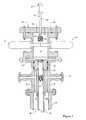
- FIG. 2is a schematic diagram of an adapter pin in accordance with the invention having a shoulder for supporting a tubing assembly, installed between a tubing hanger and tubing string supported by the tubing hanger;
- FIG. 3is a schematic diagram of a backpressure plug tool for setting or retrieving a backpressure plug
- FIG. 4schematically illustrates principal components for removing or landing a tubing hanger using the backpressure pin adapter in accordance with the present invention.
- FIG. 5schematically illustrates alternative components for removing or landing the tubing hanger using the backpressure pin adapter in accordance with the present invention.
- the inventionprovides a method for permitting the setting of a backpressure plug below a tubing hanger within reach of a backpressure plug tool.
- the methodis facilitated by backpressure pin threads in a backpressure adapter pin, which may be a tubing collar, for example.
- the backpressure pin threadsmay also be integrated with the tubing string below the tubing hanger, so that the tubing hanger may be removed or landed without setting or retrieving a wireline plug.
- the methodspermit setting the backpressure plug, and removing a tubing hanger without the use of a wireline tool.
- the backpressure adapter pin 10is a tubing joint having substantially cylindrical inner 12 and outer 14 walls, a top end 16 and a bottom end 18 .
- the top end 16is adapted to be connected to a tubing hanger, or to a pup joint connected to the tubing hanger.
- the bottom end 18is adapted to be connected to a tubing string.
- the top end 16 and bottom end 18are external upset end (EuE) threaded so that the adapter pin 10 can threadably connect to standard tubing hangers and standard tubing strings collars.
- the inner wall 12 of the adapter pin 10has backpressure threads 20 commonly used in tubing hangers for receiving and retaining a backpressure plug (not illustrated) in a fluid-tight seal.
- the adapter pin 10 illustrated in FIG. 1 ais pin threaded EuE on both the top end 16 and bottom end 18 , so that, for example, the adapter pin 10 (of FIG. 1 a ) can connect to a tubing hanger at the top end 16 , and to a tubing collar at the bottom end 18 .
- the adapter pin 10 illustrated in FIG. 1 bis box threaded EuE on both the top end 16 and bottom end 18 , so that, for example, the adapter pin 10 (of FIG. 1 b ) can be connected to a pin threaded EuE pup joint at the top end 16 and to a joint of a tubing string at the bottom end 18 .
- the adapter pin 10 shown in FIG. 1can therefore be used as a tubing collar, the use and function of which are well known in the art.
- the adapter pin 10 shown in FIG. 1 cis pin threaded EuE on the top end 16 , for coupling with a tubing hanger, for example, and box threaded EuE on the bottom end 18 , for connection to a joint of a tubing string.
- the outer wall 14 of the adapter pin 10 illustrated in FIG. 1 cincludes two weight bearing circumferential shoulders.
- a shoulder 19 ais adapted to mate with a slip block
- a shoulder 19 bis adapted to mate with a snubbing block.
- the shoulder 19 ais contoured to mate with the slip block of a slip spool, described in applicant's U.S. Pat. No. 6,695,064, issued Feb. 24, 2004, entitled SLIP SPOOL AND METHOD OF USING SAME, which is incorporated herein by reference.
- the adapter pin 10 illustrated in FIG. 1 dhas box threaded EuE top end 16 , and pin threaded EuE bottom end 18 , permitting connection of a tubing collar to the bottom end 18 , and a pup joint to the top end 16 .
- the adapter pin 10 shown in FIG. 1 dhas a circumferential shoulder 19 a which may be used to support a tubing string to which it is connected.
- the shoulder 19 a shown in FIG. 1 dis designed to be supported by substantially any slip block.
- FIG. 1 eillustrates an adapter pin 10 that is box threaded EuE on both the top end 16 and bottom end 18 , and provides shoulders 19 a for supporting and 19 b for snubbing the tubing string.
- the shoulders 19 a,bare respectively formed in a circumferential recess in the outer wall 14 .
- the adapter pin 10 shown in FIGS. 1 a - 1 eis configured with EuE threads, other thread patterns or other types of connections can be used for the same purpose.
- the illustrated adapter pins 10are straight-through adapters, the top end 16 and bottom end 18 may have different diameters, so that the adapter pin 10 also serves as a size adapter.
- the illustrated adapter pins 10are configured for use with jointed tubing, they may be readily adapted to use with coil tubing using joints and connectors that are well known in the art.
- FIG. 2illustrates part of a wellhead control stack 24 that includes a blowout preventor (BOP) 26 , and a tubing head spool 28 .
- BOPblowout preventor
- FIG. 2illustrates part of a wellhead control stack 24 that includes a blowout preventor (BOP) 26 , and a tubing head spool 28 .
- a tubing assemblythat includes of a tubing hanger 30 landed in the tubing head spool 28 , the adapter pin 10 connected to the tubing hanger 30 and to a tubing string 32 .
- the control stack 24may include other elements than the BOP 26 and the tubing head spool 28 .
- An axial passage 36extends vertically through the control stack 22 , providing access to the tubing string 32 .
- the BOP 26is illustrated in a closed condition, indicating that the axial passage is sealed. This is necessary in a live well to prevent hydrocarbons from escaping to atmosphere.
- the BOP 26normally includes a complement of blind rams adapted to seal the axial passage 36 , and a complement of tubing rams adapted to provide a fluid seal around a tubing string. If there is no obstruction in the axial passage 36 , the blind rams can be closed to seal the well bore. However, if the axial passage 36 is obstructed by the tubing string 32 , tubing rams (of appropriate configuration) are used to block the flow through the annulus 35 .
- the tubing head spool 28is mounted to the top of the well and secures the well casing 34 and supports the tubing hanger 30 .
- the illustrated tubing head spool 28further includes a pair of valves 37 used for known purposes outside of the scope of the present invention.
- the tubing hanger 30seals against an inner wall of the tubing head spool 28 , which includes at least two lock bolts 38 for locking the tubing hanger 30 against a seat of the tubing head spool 28 .
- the tubing hanger 30therefore seals the annulus 35 of the well.
- FIG. 6illustrates a procedure for using the slip spool 10 , 11 described above to install a tubing hanger 100 in a tubing head spool 102 , or to remove the tubing hanger 100 from the tubing head spool 102 .
- the tubing hanger 100must be set in the tubing head spool 102 in order to suspend the production tubing string 104 in the wellbore after the production tubing string 104 has been run into the well during well completion, as described in Applicant's co-pending U.S. patent application Ser. No. 09/791,980, entitled METHOD AND APPARATUS FOR INSERTING A TUBING HANGER INTO A LIVE WELL, which was filed on Feb.
- tubing hanger 100must be removed from the tubing head spool 102 when a mandrel of a HOP protector is to be inserted through the wellhead (see FIGs. 8 and 8 a ), as explained, for example, in Applicant's co-pending U.S. patent application Ser. No. 09/537,629entitled BLOWOUT PREVENTER PROTECTOR AND METHOD OF USING SAME, which was filed on Mar. 29, 2000 and is also incorporated herein by reference. It is also well known that slips are required to be set and removed to support the tubing string 104 during many other well completion, re-completion and maintenance procedures, particularly if the procedure requires any manipulation of the tubing string 104 .
- the adapter pin 10 shown in FIG. 2resembles the adapter pin 10 illustrated in FIG. 1 d , insofar as it provides a shoulder 19 a for supporting the tubing string 32 , but does not provide a shoulder for snubbing the tubing string 32 . It is different from the embodiment shown in FIG. 1 d in that it provides the shoulder at the bottom end 18 , rather than in the middle, and that the shoulder 19 a of the adapter pin shown FIG. 1 d is square, whereas the shoulder 19 a of the adapter pin 10 shown in FIG. 2 is beveled.
- the most convenient and economical time for installing the adapter pin 10 in a tubing stringis during completion of the well, when the tubing string is being run into the well.
- the well illustrated in FIG. 2is a live well, a pressure difference between the hydrocarbon reservoir and atmosphere propels well fluids upwards, and the fluids are blocked in the annulus 35 by the tubing hanger 30 , but can flow through the tubing string 32 into the axial passage as far as the blind rams of the BOP 26 .
- the backpressure plug tool 44includes a backpressure plug installation rod 48 having a top end 50 that permits manipulation of a backpressure plug 56 , when a bottom end 52 of the backpressure plug tool 44 is inserted into the axial passage 36 of the control stack 24 .
- the bottom end 52is adapted for coupling with an adapter head 54 .
- the adapter head 54engages the backpressure plug 56 .
- the rod 48extends through a packing 60 that permits the rod 48 to be moved rotationally and vertically, even if the axial passage 36 is under pressure.
- the outer diameter of the bottom end 52 of the rod 48may be larger than that of the rod 48 , so that the tool cannot be ejected from the pressure containment flange 46 .
- a method for inserting the backpressure plug 56 into the tubing assemblytherefore includes steps of mounting the backpressure plug tool 44 with the pressure containment flange 46 to the top of the BOP 26 .
- the axial passage 36 above the blind rams of the BOP 26is at atmospheric pressure.
- the pressure containment flange 46generally includes a pressure test port (not shown) used for pressure balancing and pressure release. Consequently, after the backpressure plug tool is installed on the BOP 26 , the well pressure is balanced across the blind rams of the BOP 26 using a pressure bleed hose (not shown) connected between the tubing head spool 28 and the backpressure containment flange 46 , in a manner well known in the art.
- the blind rams of the blowout preventor 26are then opened, the rod 48 is lowered, moving the backpressure plug 56 down through the pressurized axial passage 36 and to the tubing hanger 30 .
- the backpressure plug tool 44is used to rotate the backpressure plug 56 until it is sealingly secured in the backpressure threads 20 . This may involve using a wrench at the top end 50 of the rod 48 , in a manner known in the art.
- the axial passage 36remains under pressure, but isolated from the well pressures below the plug, as the well fluids are blocked from rising up through the tubing string 32 .
- the pressure above the backpressure plug 56is then bled off and the backpressure plug tool is removed.
- the blowout preventor 26may also be removed, as the tubing hanger 30 blocks the annulus 35 , and the backpressure plug 56 blocks the tubing string 32 , below the BOP 26 .
- Removing the backpressure plug 56 from the adapter pin 10is performed by reversing the steps described above.
- the BOP 26(if not already installed on the control stack) is installed and the blind rams are closed.
- the pressure containment flange 46 with the backpressure plug tool 44are installed and the pressure is balanced above the backpressure plug, as described above.
- the backpressure plug tool 44is then used to remove the backpressure plug 56 .
- the backpressure tool 44is then pulled up to a position above the blind rams of the BOP 26 .
- the blind ramsare closed, sealing the axial passage 36 .
- the pressureis then bled off above the blind rams of the BOP 26 , and the backpressure containment flange 46 with the backpressure plug tool 44 are removed.
- tubing hanger 30must be set in the tubing head spool 28 in order to suspend the tubing string 32 in the well after the tubing string 32 has been run into the well during well completion, as described in Applicant's U.S. Pat. No. 6,595,297 entitled METHOD AND APPARATUS FOR INSERTING A TUBING HANGER INTO A LIVE WELL, which issued on Jul. 22, 2003, the specification of which is incorporated herein by reference.
- the tubing hanger 30must be removed from the tubing head spool 28 when a mandrel of a blowout preventor protector is to be inserted through the wellhead, as explained for example, in the applicant's above-referenced U.S. Pat. No. 6,364,024.
- these proceduresinvolve removing the tubing hanger 30 from the tubing head spool 28 , and disconnecting the tubing hanger 30 from the tubing string 32 .
- the inventionprovides a method for removing the tubing hanger 30 from a live well, without having to plug the production tubing using a wireline tool.
- FIG. 4schematically illustrates a control stack 24 that includes the tubing head spool 28 , the BOP 26 , and a slip spool 70 , described in Applicant's U.S. Pat. No. 6,695,064.
- the control stack 24includes an annular adapter 72 .
- the annular adapter 72is connected to a top of the control stack 24 .
- a Bowen union 74is mounted to a top of the slip spool 70 and the annular adapter 72 is connected to the Bowen union 74 by a lockdown nut 76 .
- the annular adapter 72includes bleed-off valves 78 that control flow through radial passages 80 .
- a landing joint 86can be reciprocated through packing 82 that inhibits an escape of pressurized well fluids to atmosphere.
- the slip spool 70includes a set of slip blocks 84 that are controlled by hydraulic cylinders, as explained in detail in Applicant's U.S. Pat. No. 6,695,062. A top edge of each of the slip blocks is contoured to complement the beveled shoulder 19 a of the adapter pin 10 illustrated in FIGS. 2 , 3 & 4 .
- a tubing assembly shown in FIG. 4includes the tubing hanger 30 , the adapter pin 10 , and tubing string 32 , all of which have been described above.
- the tubing assemblyis illustrated in side elevational view, so the backpressure plug 56 , and backpressure threads 20 are not visible.
- the landing joint 86is connected to a top end of the tubing hanger 30 .
- the method of removing the tubing hanger 30 after the backpressure plug 56 is set in the adapter pin 10involves first installing the slip spool 70 and annular adapter 72 onto the top of the control stack 24 , above the BOP 26 . Once these spools are sealed and pressure balanced, the landing joint 86 is lowered down through the axial passage 36 , and into the tubing hanger 30 where it is rotated to engage box threads in a top of the tubing hanger 30 .
- the lock bolts 38are retracted and the landing joint 86 is then hoisted to raise the tubing assembly up through the control stack 24 . Hoisting the landing joint 86 unseats the tubing hanger 30 . Once the tubing hanger 30 and adapter pin 10 have been pulled up far enough to clear the tubing rams of the BOP 26 , the tubing rams may be closed around the tubing string 32 , blocking the fluid path between the axial passage above the BOP 26 and the reservoir below. After the tubing rams are closed, the bleed-off valve 78 is opened to release the pressurized fluid contained in the axial passage 36 above the tubing rams of the BOP 26 . After the adapter pin 10 is raised above a top of the slip blocks 84 , the slip blocks 84 are extended, and the landing joint 86 is lowered so that a weight of the tubing string is supported by the slip blocks 84 .
- the annular adapter 72is removed by disconnecting the landing joint 86 and unscrewing the lockdown nut 76 .
- the tubing hanger 30is therefore exposed, and can be removed. If desired, the Bowen Union 74 may also be removed.
- Steps involved in inserting the tubing hanger 30 into the tubing head spool 28are substantially the reverse of the method of removing the tubing hanger 30 , and will not be repeated here.
- slip spool 70is not essential to the procedure described above, and other slip devices can be used to temporarily support the tubing string.
- the adapter spool 72 and the landing jointmay be raised further so that the adapter pin 10 is higher than the control stack, at which point it can be supported by a conventional slip block, for example.
- FIG. 5schematically illustrates a control stack that is different form the one described above with reference to FIG. 4 .
- the slip spool 70is replaced with a hydraulic slip spool 90 that supports the tubing string 32 using slip jaws 92 , as described in Applicant's Published U.S. Patent Application No. 20030116326 published on Jun. 26, 2003 and entitled SLIP SPOOL AND METHOD OF USING SAME, the specification of which is incorporated herein by reference.
- the slip jaws 92are shown in a retracted position.
- a base plate of the hydraulic slip spool 90is provisioned with a hydraulic system 94 .
- the hydraulic system 94includes two or more hydraulic cylinder 96 operatively coupled to respective piston rods 98 . The details and operation of such a hydraulic system is well known in the art and not described here.
- the backpressure threads 20 for receiving the backpressure plug 56are incorporated in a tubing joint of the tubing string 32 .
- the inventiontherefore permits a tubing string to be plugged and a tubing hanger to be removed from a live well without the use of wireline equipment.
- the method and apparatus in accordance with the inventionpermit the backpressure plug to be set or removed more quickly than can be accomplished using a wireline lubrication, and at much less expense. Consequently, the invention permits many well completion and servicing operations to be performed more quickly at a reduced cost.
Landscapes
- Life Sciences & Earth Sciences (AREA)
- Engineering & Computer Science (AREA)
- Geology (AREA)
- Mining & Mineral Resources (AREA)
- Physics & Mathematics (AREA)
- Environmental & Geological Engineering (AREA)
- Fluid Mechanics (AREA)
- General Life Sciences & Earth Sciences (AREA)
- Geochemistry & Mineralogy (AREA)
- Earth Drilling (AREA)
Abstract
Description
Claims (20)
Priority Applications (1)
| Application Number | Priority Date | Filing Date | Title |
|---|---|---|---|
| US10/912,894US6938696B2 (en) | 2003-01-06 | 2004-08-06 | Backpressure adapter pin and methods of use |
Applications Claiming Priority (2)
| Application Number | Priority Date | Filing Date | Title |
|---|---|---|---|
| US10/336,911US6918439B2 (en) | 2003-01-03 | 2003-01-06 | Backpressure adaptor pin and methods of use |
| US10/912,894US6938696B2 (en) | 2003-01-06 | 2004-08-06 | Backpressure adapter pin and methods of use |
Related Parent Applications (1)
| Application Number | Title | Priority Date | Filing Date |
|---|---|---|---|
| US10/336,911DivisionUS6918439B2 (en) | 2003-01-03 | 2003-01-06 | Backpressure adaptor pin and methods of use |
Publications (2)
| Publication Number | Publication Date |
|---|---|
| US20050016736A1 US20050016736A1 (en) | 2005-01-27 |
| US6938696B2true US6938696B2 (en) | 2005-09-06 |
Family
ID=34078885
Family Applications (1)
| Application Number | Title | Priority Date | Filing Date |
|---|---|---|---|
| US10/912,894Expired - Fee RelatedUS6938696B2 (en) | 2003-01-06 | 2004-08-06 | Backpressure adapter pin and methods of use |
Country Status (1)
| Country | Link |
|---|---|
| US (1) | US6938696B2 (en) |
Cited By (42)
| Publication number | Priority date | Publication date | Assignee | Title |
|---|---|---|---|---|
| US20050051362A1 (en)* | 2003-09-04 | 2005-03-10 | Mcguire Bob | Drilling flange and independent screwed wellhead with metal-to-metal seal and method of use |
| US20050077043A1 (en)* | 2003-10-08 | 2005-04-14 | Dallas L. Murray | Well stimulation tool an method for inserting a backpressure plug through a mandrel of the tool |
| US20050217868A1 (en)* | 2004-03-31 | 2005-10-06 | Dallas L M | Casing-engaging well tree isolation tool and method of use |
| US20060196677A1 (en)* | 2003-06-27 | 2006-09-07 | Hwc Energy Services, Inc. | Multi-lock adapters for independent screwed wellheads and methods of using same |
| US20060237193A1 (en)* | 2003-05-13 | 2006-10-26 | Oil States Energy Services, Inc. | Casing mandrel with well stimulation tool and tubing head spool for use with the casing mandrel |
| US20070013188A1 (en)* | 2005-07-14 | 2007-01-18 | Hwces International | High-pressure threaded union with metal-to-metal seal, and metal ring gasket for same |
| US20070193734A1 (en)* | 2003-03-07 | 2007-08-23 | Stinger Wellhead Protection, Inc. | Apparatus for controlling a tool having a mandrel that must be stroked into or out of a well |
| US20070267198A1 (en)* | 2003-05-19 | 2007-11-22 | Stinger Wellhead Protection, Inc. | Casing mandrel for facilitating well completion, re-completion or workover |
| US20080087415A1 (en)* | 2004-03-17 | 2008-04-17 | Stinger Wellhead Protection, Inc. | Hybrid wellhead system and method of use |
| US20080196882A1 (en)* | 2005-07-15 | 2008-08-21 | Stinger Wellhead Protection, Inc. | Slip Spool Assembly and Method of Using Same |
| US20080277120A1 (en)* | 2007-05-11 | 2008-11-13 | Stinger Wellhead Protection, Inc. | Retrievable frac mandrel and well control stack to facilitate well completion, re-completion or workover and method of use |
| US7886833B2 (en) | 2004-03-29 | 2011-02-15 | Stinger Wellhead Protection, Inc. | System and method for low-pressure well completion |
| US8079413B2 (en) | 2008-12-23 | 2011-12-20 | W. Lynn Frazier | Bottom set downhole plug |
| USD657807S1 (en) | 2011-07-29 | 2012-04-17 | Frazier W Lynn | Configurable insert for a downhole tool |
| US8307892B2 (en) | 2009-04-21 | 2012-11-13 | Frazier W Lynn | Configurable inserts for downhole plugs |
| USD672794S1 (en) | 2011-07-29 | 2012-12-18 | Frazier W Lynn | Configurable bridge plug insert for a downhole tool |
| USD673183S1 (en) | 2011-07-29 | 2012-12-25 | Magnum Oil Tools International, Ltd. | Compact composite downhole plug |
| USD673182S1 (en) | 2011-07-29 | 2012-12-25 | Magnum Oil Tools International, Ltd. | Long range composite downhole plug |
| CN103061702A (en)* | 2012-12-30 | 2013-04-24 | 沈阳北方重矿机械有限公司 | Plugging device for double-barreled directional drilling machine |
| USD684612S1 (en) | 2011-07-29 | 2013-06-18 | W. Lynn Frazier | Configurable caged ball insert for a downhole tool |
| US8496052B2 (en) | 2008-12-23 | 2013-07-30 | Magnum Oil Tools International, Ltd. | Bottom set down hole tool |
| USD694281S1 (en) | 2011-07-29 | 2013-11-26 | W. Lynn Frazier | Lower set insert with a lower ball seat for a downhole plug |
| USD694280S1 (en) | 2011-07-29 | 2013-11-26 | W. Lynn Frazier | Configurable insert for a downhole plug |
| USD698370S1 (en) | 2011-07-29 | 2014-01-28 | W. Lynn Frazier | Lower set caged ball insert for a downhole plug |
| USD703713S1 (en) | 2011-07-29 | 2014-04-29 | W. Lynn Frazier | Configurable caged ball insert for a downhole tool |
| US8899317B2 (en) | 2008-12-23 | 2014-12-02 | W. Lynn Frazier | Decomposable pumpdown ball for downhole plugs |
| US9109428B2 (en) | 2009-04-21 | 2015-08-18 | W. Lynn Frazier | Configurable bridge plugs and methods for using same |
| US9127527B2 (en) | 2009-04-21 | 2015-09-08 | W. Lynn Frazier | Decomposable impediments for downhole tools and methods for using same |
| US9163477B2 (en) | 2009-04-21 | 2015-10-20 | W. Lynn Frazier | Configurable downhole tools and methods for using same |
| US9181772B2 (en) | 2009-04-21 | 2015-11-10 | W. Lynn Frazier | Decomposable impediments for downhole plugs |
| US9217319B2 (en) | 2012-05-18 | 2015-12-22 | Frazier Technologies, L.L.C. | High-molecular-weight polyglycolides for hydrocarbon recovery |
| USRE46028E1 (en) | 2003-05-15 | 2016-06-14 | Kureha Corporation | Method and apparatus for delayed flow or pressure change in wells |
| US9506309B2 (en) | 2008-12-23 | 2016-11-29 | Frazier Ball Invention, LLC | Downhole tools having non-toxic degradable elements |
| US9562415B2 (en) | 2009-04-21 | 2017-02-07 | Magnum Oil Tools International, Ltd. | Configurable inserts for downhole plugs |
| US9587475B2 (en) | 2008-12-23 | 2017-03-07 | Frazier Ball Invention, LLC | Downhole tools having non-toxic degradable elements and their methods of use |
| US9708878B2 (en) | 2003-05-15 | 2017-07-18 | Kureha Corporation | Applications of degradable polymer for delayed mechanical changes in wells |
| US11053769B2 (en) | 2019-02-02 | 2021-07-06 | Northern Oil Solutions | Back pressure valve plug |
| US11208856B2 (en) | 2018-11-02 | 2021-12-28 | Downing Wellhead Equipment, Llc | Subterranean formation fracking and well stack connector |
| US11242950B2 (en) | 2019-06-10 | 2022-02-08 | Downing Wellhead Equipment, Llc | Hot swappable fracking pump system |
| US20220412183A1 (en)* | 2019-12-20 | 2022-12-29 | Cameron International Corporation | System and method for setting a barrier in a well string |
| US11702900B2 (en) | 2020-07-31 | 2023-07-18 | Cameron International Corporation | Double grip retention for wellbore installations |
| US11719073B2 (en)* | 2020-07-31 | 2023-08-08 | Cameron International Corporation | Snub friendly wellhead hanger |
Families Citing this family (2)
| Publication number | Priority date | Publication date | Assignee | Title |
|---|---|---|---|---|
| US11473388B2 (en) | 2021-03-12 | 2022-10-18 | Saudi Arabian Oil Company | Tubing head adapters with multiple back pressure valves and methods of isolating production tubing |
| US12276177B2 (en) | 2021-05-29 | 2025-04-15 | Onesubsea Ip Uk Limited | Flow path and bore management system and method |
Citations (25)
| Publication number | Priority date | Publication date | Assignee | Title |
|---|---|---|---|---|
| US2233077A (en) | 1938-10-10 | 1941-02-25 | Barker | Well controlling apparatus |
| US2830666A (en) | 1956-07-12 | 1958-04-15 | George A Butler | Combined sealing plug and tubing hanger |
| US2939534A (en) | 1956-04-10 | 1960-06-07 | Cameron Iron Works Inc | Sealed telescopic connection |
| US4825945A (en) | 1988-03-21 | 1989-05-02 | Cameron Iron Works Usa, Inc. | Wellhead valve |
| US4860826A (en)* | 1988-01-28 | 1989-08-29 | Land John L | Apparatus for sealing a tubing string in a high pressure wellbore |
| US4923006A (en) | 1989-08-07 | 1990-05-08 | Cameron Iron Works Usa, Inc. | Insulating support for tubing string |
| US5012865A (en) | 1989-09-26 | 1991-05-07 | Mcleod Roderick D | Annular and concentric flow wellhead isolation tool |
| US5020590A (en) | 1988-12-01 | 1991-06-04 | Mcleod Roderick D | Back pressure plug tool |
| US5515925A (en) | 1994-09-19 | 1996-05-14 | Boychuk; Randy J. | Apparatus and method for installing coiled tubing in a well |
| US5785121A (en) | 1996-06-12 | 1998-07-28 | Dallas; L. Murray | Blowout preventer protector and method of using same during oil and gas well stimulation |
| US5819851A (en) | 1997-01-16 | 1998-10-13 | Dallas; L. Murray | Blowout preventer protector for use during high pressure oil/gas well stimulation |
| US5988273A (en) | 1997-09-03 | 1999-11-23 | Abb Vetco Gray Inc. | Coiled tubing completion system |
| US5988274A (en) | 1997-07-30 | 1999-11-23 | Funk; Kelly | Method of and apparatus for inserting pipes and tools into wells |
| US6012519A (en) | 1998-02-09 | 2000-01-11 | Erc Industries, Inc. | Full bore tubing hanger system |
| US6145596A (en) | 1999-03-16 | 2000-11-14 | Dallas; L. Murray | Method and apparatus for dual string well tree isolation |
| US6209633B1 (en) | 1997-12-17 | 2001-04-03 | Michael Jonathon Haynes | Apparatus and method for axially displacing a downhole tool or a tubing string in a well bore |
| US6220363B1 (en) | 1999-07-16 | 2001-04-24 | L. Murray Dallas | Wellhead isolation tool and method of using same |
| US6234253B1 (en) | 1998-11-30 | 2001-05-22 | L. Murray Dallas | Method and apparatus for well workover or servicing |
| US6289993B1 (en) | 1999-06-21 | 2001-09-18 | L. Murray Dallas | Blowout preventer protector and setting tool |
| US6328111B1 (en)* | 1999-02-24 | 2001-12-11 | Baker Hughes Incorporated | Live well deployment of electrical submersible pump |
| US6364024B1 (en) | 2000-01-28 | 2002-04-02 | L. Murray Dallas | Blowout preventer protector and method of using same |
| US6510900B2 (en) | 2001-02-08 | 2003-01-28 | L. Murray Dallas | Seal assembly for dual string coil tubing injection and method of use |
| US6595297B2 (en) | 2001-02-23 | 2003-07-22 | L. Murray Dallas | Method and apparatus for inserting a tubing hanger into a live well |
| US6695064B2 (en) | 2001-12-19 | 2004-02-24 | L. Murray Dallas | Slip spool and method of using same |
| US6769489B2 (en) | 2001-11-28 | 2004-08-03 | L. Murray Dallas | Well stimulation tool and method of using same |
- 2004
- 2004-08-06USUS10/912,894patent/US6938696B2/ennot_activeExpired - Fee Related
Patent Citations (25)
| Publication number | Priority date | Publication date | Assignee | Title |
|---|---|---|---|---|
| US2233077A (en) | 1938-10-10 | 1941-02-25 | Barker | Well controlling apparatus |
| US2939534A (en) | 1956-04-10 | 1960-06-07 | Cameron Iron Works Inc | Sealed telescopic connection |
| US2830666A (en) | 1956-07-12 | 1958-04-15 | George A Butler | Combined sealing plug and tubing hanger |
| US4860826A (en)* | 1988-01-28 | 1989-08-29 | Land John L | Apparatus for sealing a tubing string in a high pressure wellbore |
| US4825945A (en) | 1988-03-21 | 1989-05-02 | Cameron Iron Works Usa, Inc. | Wellhead valve |
| US5020590A (en) | 1988-12-01 | 1991-06-04 | Mcleod Roderick D | Back pressure plug tool |
| US4923006A (en) | 1989-08-07 | 1990-05-08 | Cameron Iron Works Usa, Inc. | Insulating support for tubing string |
| US5012865A (en) | 1989-09-26 | 1991-05-07 | Mcleod Roderick D | Annular and concentric flow wellhead isolation tool |
| US5515925A (en) | 1994-09-19 | 1996-05-14 | Boychuk; Randy J. | Apparatus and method for installing coiled tubing in a well |
| US5785121A (en) | 1996-06-12 | 1998-07-28 | Dallas; L. Murray | Blowout preventer protector and method of using same during oil and gas well stimulation |
| US5819851A (en) | 1997-01-16 | 1998-10-13 | Dallas; L. Murray | Blowout preventer protector for use during high pressure oil/gas well stimulation |
| US5988274A (en) | 1997-07-30 | 1999-11-23 | Funk; Kelly | Method of and apparatus for inserting pipes and tools into wells |
| US5988273A (en) | 1997-09-03 | 1999-11-23 | Abb Vetco Gray Inc. | Coiled tubing completion system |
| US6209633B1 (en) | 1997-12-17 | 2001-04-03 | Michael Jonathon Haynes | Apparatus and method for axially displacing a downhole tool or a tubing string in a well bore |
| US6012519A (en) | 1998-02-09 | 2000-01-11 | Erc Industries, Inc. | Full bore tubing hanger system |
| US6234253B1 (en) | 1998-11-30 | 2001-05-22 | L. Murray Dallas | Method and apparatus for well workover or servicing |
| US6328111B1 (en)* | 1999-02-24 | 2001-12-11 | Baker Hughes Incorporated | Live well deployment of electrical submersible pump |
| US6145596A (en) | 1999-03-16 | 2000-11-14 | Dallas; L. Murray | Method and apparatus for dual string well tree isolation |
| US6289993B1 (en) | 1999-06-21 | 2001-09-18 | L. Murray Dallas | Blowout preventer protector and setting tool |
| US6220363B1 (en) | 1999-07-16 | 2001-04-24 | L. Murray Dallas | Wellhead isolation tool and method of using same |
| US6364024B1 (en) | 2000-01-28 | 2002-04-02 | L. Murray Dallas | Blowout preventer protector and method of using same |
| US6510900B2 (en) | 2001-02-08 | 2003-01-28 | L. Murray Dallas | Seal assembly for dual string coil tubing injection and method of use |
| US6595297B2 (en) | 2001-02-23 | 2003-07-22 | L. Murray Dallas | Method and apparatus for inserting a tubing hanger into a live well |
| US6769489B2 (en) | 2001-11-28 | 2004-08-03 | L. Murray Dallas | Well stimulation tool and method of using same |
| US6695064B2 (en) | 2001-12-19 | 2004-02-24 | L. Murray Dallas | Slip spool and method of using same |
Cited By (92)
| Publication number | Priority date | Publication date | Assignee | Title |
|---|---|---|---|---|
| US20070193734A1 (en)* | 2003-03-07 | 2007-08-23 | Stinger Wellhead Protection, Inc. | Apparatus for controlling a tool having a mandrel that must be stroked into or out of a well |
| US7438126B2 (en) | 2003-03-07 | 2008-10-21 | Stinger Wellhead Protection, Inc. | Apparatus for controlling a tool having a mandrel that must be stroked into or out of a well |
| US20060237193A1 (en)* | 2003-05-13 | 2006-10-26 | Oil States Energy Services, Inc. | Casing mandrel with well stimulation tool and tubing head spool for use with the casing mandrel |
| US7422070B2 (en) | 2003-05-13 | 2008-09-09 | Stinger Wellhead Protection, Inc. | Casing mandrel with well stimulation tool and tubing head spool for use with the casing mandrel |
| US20100012329A1 (en)* | 2003-05-13 | 2010-01-21 | Stinger Wellhead Protection, Inc. | Casing mandrel for facilitating well completion, re-completion or workover |
| US7921923B2 (en) | 2003-05-13 | 2011-04-12 | Stinger Wellhead Protection, Inc. | Casing mandrel for facilitating well completion, re-completion or workover |
| US8157005B2 (en) | 2003-05-13 | 2012-04-17 | Stinger Wellhead Protection, Inc. | Casing mandrel for facilitating well completion, re-completion or workover |
| US7237615B2 (en) | 2003-05-13 | 2007-07-03 | Stinger Wellhead Protection, Inc. | Casing mandrel with well stimulation tool and tubing head spool for use with the casing mandrel |
| US20110180252A1 (en)* | 2003-05-13 | 2011-07-28 | Stinger Wellhead Protection, Inc. | Casing mandrel for facilitating well completion, re-completion or workover |
| USRE46028E1 (en) | 2003-05-15 | 2016-06-14 | Kureha Corporation | Method and apparatus for delayed flow or pressure change in wells |
| US9708878B2 (en) | 2003-05-15 | 2017-07-18 | Kureha Corporation | Applications of degradable polymer for delayed mechanical changes in wells |
| US10280703B2 (en) | 2003-05-15 | 2019-05-07 | Kureha Corporation | Applications of degradable polymer for delayed mechanical changes in wells |
| US20070267198A1 (en)* | 2003-05-19 | 2007-11-22 | Stinger Wellhead Protection, Inc. | Casing mandrel for facilitating well completion, re-completion or workover |
| US7604058B2 (en) | 2003-05-19 | 2009-10-20 | Stinger Wellhead Protection, Inc. | Casing mandrel for facilitating well completion, re-completion or workover |
| US20070277968A1 (en)* | 2003-06-27 | 2007-12-06 | Stinger Wellhead Protection, Inc. | Multi-lock adapters for independent screwed wellheads and methods of using same |
| US7984758B2 (en) | 2003-06-27 | 2011-07-26 | Stinger Wellhead Protection, Inc. | Multi-lock adapters for independent screwed wellheads and methods of using same |
| US20090025925A1 (en)* | 2003-06-27 | 2009-01-29 | Stinger Wellhead Protection, Inc. | Multi-lock adapters for independent screwed wellheads and methods of using same |
| US20100181063A1 (en)* | 2003-06-27 | 2010-07-22 | Stinger Wellhead Protection, Inc. | Multi-lock adapters for independent screwed wellheads and methods of using same |
| US7708079B2 (en) | 2003-06-27 | 2010-05-04 | Stinger Wellhead Protection, Inc. | Multi-lock adapters for independent screwed wellheads and methods of using same |
| US8100185B2 (en) | 2003-06-27 | 2012-01-24 | Stinger Wellhead Protection, Inc. | Multi-lock adapters for independent screwed wellheads and methods of using same |
| US7428931B2 (en) | 2003-06-27 | 2008-09-30 | Stinger Wellhead Protection, Inc. | Multi-lock adapters for independent screwed wellheads and methods of using same |
| US7267180B2 (en) | 2003-06-27 | 2007-09-11 | Stinger Wellhead Protection, Inc. | Multi-lock adapters for independent screwed wellheads and methods of using same |
| US20060196677A1 (en)* | 2003-06-27 | 2006-09-07 | Hwc Energy Services, Inc. | Multi-lock adapters for independent screwed wellheads and methods of using same |
| US7475721B2 (en) | 2003-09-04 | 2009-01-13 | Stinger Wellhead Protection, Inc. | Drilling flange and independent screwed wellhead with metal-to-metal seal and method of use |
| US7350562B2 (en) | 2003-09-04 | 2008-04-01 | Stinger Wellhead Protection, Inc. | Drilling flange and independent screwed wellhead with metal-to-metal seal and method of use |
| US20090084538A1 (en)* | 2003-09-04 | 2009-04-02 | Stinger Wellhead Protection, Inc. | Drilling flange and independent screwed wellhead with metal-to-metal seal and method of use |
| US20080142210A1 (en)* | 2003-09-04 | 2008-06-19 | Stinger Wellhead Protection, Inc. | Drilling Flange and Independent Screwed Wellhead With Metal-to-Metal Seal and Method of Use |
| US20050051362A1 (en)* | 2003-09-04 | 2005-03-10 | Mcguire Bob | Drilling flange and independent screwed wellhead with metal-to-metal seal and method of use |
| US7159652B2 (en) | 2003-09-04 | 2007-01-09 | Oil States Energy Services, Inc. | Drilling flange and independent screwed wellhead with metal-to-metal seal and method of use |
| US7650936B2 (en) | 2003-09-04 | 2010-01-26 | Stinger Wellhead Protection, Inc. | Drilling flange and independent screwed wellhead with metal-to-metal seal and method of use |
| US7055632B2 (en) | 2003-10-08 | 2006-06-06 | H W C Energy Services, Inc. | Well stimulation tool and method for inserting a backpressure plug through a mandrel of the tool |
| US20050077043A1 (en)* | 2003-10-08 | 2005-04-14 | Dallas L. Murray | Well stimulation tool an method for inserting a backpressure plug through a mandrel of the tool |
| US8118090B2 (en) | 2004-03-17 | 2012-02-21 | Stinger Wellhead Protection, Inc. | Hybrid wellhead system and method of use |
| US7721808B2 (en) | 2004-03-17 | 2010-05-25 | Stinger Wellhead Protection, Inc. | Hybrid wellhead system and method of use |
| US7481269B2 (en) | 2004-03-17 | 2009-01-27 | Stinger Wellhead Protection, Inc. | Hybrid wellhead system and method of use |
| US20100218939A1 (en)* | 2004-03-17 | 2010-09-02 | Stinger Wellhead Protection, Inc. | Hybrid wellhead system and method of use |
| US20110198074A1 (en)* | 2004-03-17 | 2011-08-18 | Stinger Wellhead Protection, Inc. | Hybrid wellhead system and method of use |
| US7905293B2 (en) | 2004-03-17 | 2011-03-15 | Stinger Wellhead Protection, Inc. | Hybrid wellhead system and method of use |
| US20080087415A1 (en)* | 2004-03-17 | 2008-04-17 | Stinger Wellhead Protection, Inc. | Hybrid wellhead system and method of use |
| US7886833B2 (en) | 2004-03-29 | 2011-02-15 | Stinger Wellhead Protection, Inc. | System and method for low-pressure well completion |
| US20050217868A1 (en)* | 2004-03-31 | 2005-10-06 | Dallas L M | Casing-engaging well tree isolation tool and method of use |
| US7168495B2 (en) | 2004-03-31 | 2007-01-30 | Oil States Energy Services, Inc. | Casing-engaging well tree isolation tool and method of use |
| US7654585B2 (en) | 2005-07-14 | 2010-02-02 | Stinger Wellhead Protection, Inc. | High-pressure threaded union with metal-to-metal seal, and metal ring gasket for same |
| US20110175349A1 (en)* | 2005-07-14 | 2011-07-21 | Stinger Wellhead Protection, Inc. | High-pressure threaded union with metal-to-metal seal, and metal ring gasket for same |
| US7922216B2 (en) | 2005-07-14 | 2011-04-12 | Stinger Wellhead Protection, Inc. | High-pressure threaded union with metal-to-metal seal, and metal ring gasket for same |
| US20070013188A1 (en)* | 2005-07-14 | 2007-01-18 | Hwces International | High-pressure threaded union with metal-to-metal seal, and metal ring gasket for same |
| US20090091131A1 (en)* | 2005-07-14 | 2009-04-09 | Stinger Wellhead Protection, Inc. | High-pressure threaded union with metal-to-metal seal, and metal ring gasket for same |
| US8205916B2 (en) | 2005-07-14 | 2012-06-26 | Stinger Wellhead Protection, Inc. | High-pressure threaded union with metal-to-metal seal, and metal ring gasket for same |
| US7484776B2 (en) | 2005-07-14 | 2009-02-03 | Stinger Wellhead Protection, Inc. | High-pressure threaded union with metal-to-metal seal, and metal ring gasket for same |
| US7967086B2 (en) | 2005-07-15 | 2011-06-28 | Stinger Wellhead Protection, Inc. | Slip spool assembly and method of using same |
| US20100258294A1 (en)* | 2005-07-15 | 2010-10-14 | Stinger Wellhead Protection, Inc. | Slip spool assembly and method of using same |
| US7743856B2 (en) | 2005-07-15 | 2010-06-29 | Stinger Wellhead Protection, Inc. | Slip spool assembly and method of using same |
| US20080196882A1 (en)* | 2005-07-15 | 2008-08-21 | Stinger Wellhead Protection, Inc. | Slip Spool Assembly and Method of Using Same |
| US7806175B2 (en) | 2007-05-11 | 2010-10-05 | Stinger Wellhead Protection, Inc. | Retrivevable frac mandrel and well control stack to facilitate well completion, re-completion or workover and method of use |
| US20080277120A1 (en)* | 2007-05-11 | 2008-11-13 | Stinger Wellhead Protection, Inc. | Retrievable frac mandrel and well control stack to facilitate well completion, re-completion or workover and method of use |
| US9309744B2 (en) | 2008-12-23 | 2016-04-12 | Magnum Oil Tools International, Ltd. | Bottom set downhole plug |
| US9506309B2 (en) | 2008-12-23 | 2016-11-29 | Frazier Ball Invention, LLC | Downhole tools having non-toxic degradable elements |
| US9587475B2 (en) | 2008-12-23 | 2017-03-07 | Frazier Ball Invention, LLC | Downhole tools having non-toxic degradable elements and their methods of use |
| US8079413B2 (en) | 2008-12-23 | 2011-12-20 | W. Lynn Frazier | Bottom set downhole plug |
| US8459346B2 (en) | 2008-12-23 | 2013-06-11 | Magnum Oil Tools International Ltd | Bottom set downhole plug |
| US8899317B2 (en) | 2008-12-23 | 2014-12-02 | W. Lynn Frazier | Decomposable pumpdown ball for downhole plugs |
| US8496052B2 (en) | 2008-12-23 | 2013-07-30 | Magnum Oil Tools International, Ltd. | Bottom set down hole tool |
| USD697088S1 (en) | 2008-12-23 | 2014-01-07 | W. Lynn Frazier | Lower set insert for a downhole plug for use in a wellbore |
| USD694282S1 (en) | 2008-12-23 | 2013-11-26 | W. Lynn Frazier | Lower set insert for a downhole plug for use in a wellbore |
| US8307892B2 (en) | 2009-04-21 | 2012-11-13 | Frazier W Lynn | Configurable inserts for downhole plugs |
| US9127527B2 (en) | 2009-04-21 | 2015-09-08 | W. Lynn Frazier | Decomposable impediments for downhole tools and methods for using same |
| US9181772B2 (en) | 2009-04-21 | 2015-11-10 | W. Lynn Frazier | Decomposable impediments for downhole plugs |
| US9163477B2 (en) | 2009-04-21 | 2015-10-20 | W. Lynn Frazier | Configurable downhole tools and methods for using same |
| US9562415B2 (en) | 2009-04-21 | 2017-02-07 | Magnum Oil Tools International, Ltd. | Configurable inserts for downhole plugs |
| US9062522B2 (en) | 2009-04-21 | 2015-06-23 | W. Lynn Frazier | Configurable inserts for downhole plugs |
| US9109428B2 (en) | 2009-04-21 | 2015-08-18 | W. Lynn Frazier | Configurable bridge plugs and methods for using same |
| USD694281S1 (en) | 2011-07-29 | 2013-11-26 | W. Lynn Frazier | Lower set insert with a lower ball seat for a downhole plug |
| USD703713S1 (en) | 2011-07-29 | 2014-04-29 | W. Lynn Frazier | Configurable caged ball insert for a downhole tool |
| USD698370S1 (en) | 2011-07-29 | 2014-01-28 | W. Lynn Frazier | Lower set caged ball insert for a downhole plug |
| USD673183S1 (en) | 2011-07-29 | 2012-12-25 | Magnum Oil Tools International, Ltd. | Compact composite downhole plug |
| USD672794S1 (en) | 2011-07-29 | 2012-12-18 | Frazier W Lynn | Configurable bridge plug insert for a downhole tool |
| USD694280S1 (en) | 2011-07-29 | 2013-11-26 | W. Lynn Frazier | Configurable insert for a downhole plug |
| USD657807S1 (en) | 2011-07-29 | 2012-04-17 | Frazier W Lynn | Configurable insert for a downhole tool |
| USD684612S1 (en) | 2011-07-29 | 2013-06-18 | W. Lynn Frazier | Configurable caged ball insert for a downhole tool |
| USD673182S1 (en) | 2011-07-29 | 2012-12-25 | Magnum Oil Tools International, Ltd. | Long range composite downhole plug |
| US9217319B2 (en) | 2012-05-18 | 2015-12-22 | Frazier Technologies, L.L.C. | High-molecular-weight polyglycolides for hydrocarbon recovery |
| CN103061702A (en)* | 2012-12-30 | 2013-04-24 | 沈阳北方重矿机械有限公司 | Plugging device for double-barreled directional drilling machine |
| US11208856B2 (en) | 2018-11-02 | 2021-12-28 | Downing Wellhead Equipment, Llc | Subterranean formation fracking and well stack connector |
| US11053769B2 (en) | 2019-02-02 | 2021-07-06 | Northern Oil Solutions | Back pressure valve plug |
| US11242950B2 (en) | 2019-06-10 | 2022-02-08 | Downing Wellhead Equipment, Llc | Hot swappable fracking pump system |
| US20220412183A1 (en)* | 2019-12-20 | 2022-12-29 | Cameron International Corporation | System and method for setting a barrier in a well string |
| US12065898B2 (en)* | 2019-12-20 | 2024-08-20 | Cameron International Corporation | System and method for setting a barrier in a well string |
| US11702900B2 (en) | 2020-07-31 | 2023-07-18 | Cameron International Corporation | Double grip retention for wellbore installations |
| US11719073B2 (en)* | 2020-07-31 | 2023-08-08 | Cameron International Corporation | Snub friendly wellhead hanger |
| US20230304381A1 (en)* | 2020-07-31 | 2023-09-28 | Cameron International Corporation | Snub friendly wellhead hanger |
| US12006792B2 (en)* | 2020-07-31 | 2024-06-11 | Cameron International Corporation | Snub friendly wellhead hanger |
| US12152455B2 (en) | 2020-07-31 | 2024-11-26 | Cameron International Corporation | Double grip retention for wellbore installations |
Also Published As
| Publication number | Publication date |
|---|---|
| US20050016736A1 (en) | 2005-01-27 |
Similar Documents
| Publication | Publication Date | Title |
|---|---|---|
| US6938696B2 (en) | Backpressure adapter pin and methods of use | |
| US6918439B2 (en) | Backpressure adaptor pin and methods of use | |
| CA2388664C (en) | Well stimulation tool and method of using same | |
| US6595297B2 (en) | Method and apparatus for inserting a tubing hanger into a live well | |
| US6769489B2 (en) | Well stimulation tool and method of using same | |
| US6626245B1 (en) | Blowout preventer protector and method of using same | |
| US7578351B2 (en) | Configurable wellhead system with permanent fracturing spool and method of use | |
| US7921923B2 (en) | Casing mandrel for facilitating well completion, re-completion or workover | |
| US6364024B1 (en) | Blowout preventer protector and method of using same | |
| CA2363710C (en) | Spool for pressure containment used in rigless well completion, re-completion, servicing or workover | |
| US7422070B2 (en) | Casing mandrel with well stimulation tool and tubing head spool for use with the casing mandrel | |
| US7806175B2 (en) | Retrivevable frac mandrel and well control stack to facilitate well completion, re-completion or workover and method of use | |
| CA2268557C (en) | Method and apparatus for dual string well tree isolation | |
| US7584798B2 (en) | Subsurface lubricator and method of use | |
| US6695064B2 (en) | Slip spool and method of using same | |
| US7775288B2 (en) | Retrievable frac mandrel and well control stack to facilitate well completion, re-completion or workover and method of use | |
| US4076079A (en) | Full bore fracture treating assembly | |
| US6948565B2 (en) | Slip spool and method of using same | |
| CA2338097C (en) | Method and apparatus for inserting a tubing hanger into a live well | |
| CA2412911C (en) | Well stimulation tool and method of using same | |
| CA2414867C (en) | Slip spool and method of using same |
Legal Events
| Date | Code | Title | Description |
|---|---|---|---|
| AS | Assignment | Owner name:HWCES INTERNATIONAL, TEXAS Free format text:ASSIGNMENT OF ASSIGNORS INTEREST;ASSIGNOR:DALLAS, L. MURRAY;REEL/FRAME:016712/0677 Effective date:20050501 | |
| AS | Assignment | Owner name:HWC ENERGY SERVICES, INC., TEXAS Free format text:ASSIGNMENT OF ASSIGNORS INTEREST;ASSIGNOR:HWCES INTERNATIONAL;REEL/FRAME:017636/0559 Effective date:20060228 | |
| AS | Assignment | Owner name:OIL STATES ENERGY SERVICES, INC, TEXAS Free format text:CHANGE OF NAME;ASSIGNOR:HWC ENERGY SERVICE, INC.;REEL/FRAME:017957/0310 Effective date:20060309 | |
| AS | Assignment | Owner name:STINGER WELLHEAD PROTECTION, INC., TEXAS Free format text:ASSIGNMENT OF ASSIGNORS INTEREST;ASSIGNOR:OIL STATES ENERGY SERVICES, INC.;REEL/FRAME:018767/0230 Effective date:20061219 | |
| AS | Assignment | Owner name:STINGER WELLHEAD PROTECTION, INC., OKLAHOMA Free format text:CHANGE OF ASSIGNEE ADDRESS;ASSIGNOR:STINGER WELLHEAD PROTECTION, INC.;REEL/FRAME:019588/0172 Effective date:20070716 Owner name:STINGER WELLHEAD PROTECTION, INC.,OKLAHOMA Free format text:CHANGE OF ASSIGNEE ADDRESS;ASSIGNOR:STINGER WELLHEAD PROTECTION, INC.;REEL/FRAME:019588/0172 Effective date:20070716 | |
| CC | Certificate of correction | ||
| REMI | Maintenance fee reminder mailed | ||
| LAPS | Lapse for failure to pay maintenance fees | ||
| STCH | Information on status: patent discontinuation | Free format text:PATENT EXPIRED DUE TO NONPAYMENT OF MAINTENANCE FEES UNDER 37 CFR 1.362 | |
| FP | Lapsed due to failure to pay maintenance fee | Effective date:20090906 |