US6937738B2 - Digital hearing aid system - Google Patents
Digital hearing aid systemDownload PDFInfo
- Publication number
- US6937738B2 US6937738B2US10/121,221US12122102AUS6937738B2US 6937738 B2US6937738 B2US 6937738B2US 12122102 AUS12122102 AUS 12122102AUS 6937738 B2US6937738 B2US 6937738B2
- Authority
- US
- United States
- Prior art keywords
- signal
- digital
- microphone
- analog
- occlusion
- Prior art date
- Legal status (The legal status is an assumption and is not a legal conclusion. Google has not performed a legal analysis and makes no representation as to the accuracy of the status listed.)
- Expired - Lifetime, expires
Links
Images


Classifications
- H—ELECTRICITY
- H04—ELECTRIC COMMUNICATION TECHNIQUE
- H04R—LOUDSPEAKERS, MICROPHONES, GRAMOPHONE PICK-UPS OR LIKE ACOUSTIC ELECTROMECHANICAL TRANSDUCERS; DEAF-AID SETS; PUBLIC ADDRESS SYSTEMS
- H04R25/00—Deaf-aid sets, i.e. electro-acoustic or electro-mechanical hearing aids; Electric tinnitus maskers providing an auditory perception
- H04R25/40—Arrangements for obtaining a desired directivity characteristic
- H04R25/407—Circuits for combining signals of a plurality of transducers
- H—ELECTRICITY
- H04—ELECTRIC COMMUNICATION TECHNIQUE
- H04R—LOUDSPEAKERS, MICROPHONES, GRAMOPHONE PICK-UPS OR LIKE ACOUSTIC ELECTROMECHANICAL TRANSDUCERS; DEAF-AID SETS; PUBLIC ADDRESS SYSTEMS
- H04R25/00—Deaf-aid sets, i.e. electro-acoustic or electro-mechanical hearing aids; Electric tinnitus maskers providing an auditory perception
- H04R25/35—Deaf-aid sets, i.e. electro-acoustic or electro-mechanical hearing aids; Electric tinnitus maskers providing an auditory perception using translation techniques
- H04R25/356—Amplitude, e.g. amplitude shift or compression
- H—ELECTRICITY
- H04—ELECTRIC COMMUNICATION TECHNIQUE
- H04R—LOUDSPEAKERS, MICROPHONES, GRAMOPHONE PICK-UPS OR LIKE ACOUSTIC ELECTROMECHANICAL TRANSDUCERS; DEAF-AID SETS; PUBLIC ADDRESS SYSTEMS
- H04R2225/00—Details of deaf aids covered by H04R25/00, not provided for in any of its subgroups
- H04R2225/43—Signal processing in hearing aids to enhance the speech intelligibility
- H—ELECTRICITY
- H04—ELECTRIC COMMUNICATION TECHNIQUE
- H04R—LOUDSPEAKERS, MICROPHONES, GRAMOPHONE PICK-UPS OR LIKE ACOUSTIC ELECTROMECHANICAL TRANSDUCERS; DEAF-AID SETS; PUBLIC ADDRESS SYSTEMS
- H04R2460/00—Details of hearing devices, i.e. of ear- or headphones covered by H04R1/10 or H04R5/033 but not provided for in any of their subgroups, or of hearing aids covered by H04R25/00 but not provided for in any of its subgroups
- H04R2460/05—Electronic compensation of the occlusion effect
- H—ELECTRICITY
- H04—ELECTRIC COMMUNICATION TECHNIQUE
- H04R—LOUDSPEAKERS, MICROPHONES, GRAMOPHONE PICK-UPS OR LIKE ACOUSTIC ELECTROMECHANICAL TRANSDUCERS; DEAF-AID SETS; PUBLIC ADDRESS SYSTEMS
- H04R25/00—Deaf-aid sets, i.e. electro-acoustic or electro-mechanical hearing aids; Electric tinnitus maskers providing an auditory perception
- H04R25/45—Prevention of acoustic reaction, i.e. acoustic oscillatory feedback
- H04R25/453—Prevention of acoustic reaction, i.e. acoustic oscillatory feedback electronically
- H—ELECTRICITY
- H04—ELECTRIC COMMUNICATION TECHNIQUE
- H04R—LOUDSPEAKERS, MICROPHONES, GRAMOPHONE PICK-UPS OR LIKE ACOUSTIC ELECTROMECHANICAL TRANSDUCERS; DEAF-AID SETS; PUBLIC ADDRESS SYSTEMS
- H04R25/00—Deaf-aid sets, i.e. electro-acoustic or electro-mechanical hearing aids; Electric tinnitus maskers providing an auditory perception
- H04R25/50—Customised settings for obtaining desired overall acoustical characteristics
- H04R25/505—Customised settings for obtaining desired overall acoustical characteristics using digital signal processing
Definitions
- This inventiongenerally relates to hearing aids. More specifically, the invention provides an advanced digital hearing aid system.
- one embodiment of the present inventionincludes an occlusion sub-system which compensates for the amplification of the digital hearing aid user's own voice within the ear canal.
- Another embodiment of the present inventionincludes a directional processor and a headroom expander which optimize the gain applied to the acoustical signals received by the digital hearing aid and combine the amplified signals into a directionally-sensitive response.
- the present inventionincludes other advantages over known digital hearing aids, as described below.
- a digital hearing aidincludes front and rear microphones, a sound processor, and a speaker.
- Embodiments of the digital hearing aidinclude an occlusion subsystem, and a directional processor and headroom expander.
- the front microphonereceives a front microphone acoustical signal and generates a front microphone analog signal.
- the rear microphonereceives a rear microphone acoustical signal and generates a rear microphone analog signal.
- the front and rear microphone analog signalsare converted into the digital domain, and at least the front microphone signal is coupled to the sound processor.
- the sound processorselectively modifies the signal characteristics and generates a processed signal.
- the processed signalis coupled to the speaker which converts the signal to an acoustical hearing aid output signal that is directed into the ear canal of the digital hearing aid user.
- the occlusion sub-systemcompensates for the amplification of the digital hearing aid user's own voice within the ear canal.
- the directional processor and headroom expanderoptimizes the gain applied to the acoustical signals received by the digital hearing aid and combine the amplified signals into a directionally-sensitive response.
- FIG. 1is a block diagram of an exemplary digital hearing aid system according to the present invention
- FIG. 2is a block diagram of an occlusion sub-system for the digital hearing aid system shown in FIG. 1 ;
- FIG. 3is a graph showing an exemplary frequency response for the frequency equalizer block shown in FIG. 2 ;
- FIG. 4is a more detailed block diagram of the headroom expander and analog-to-digital converters shown in FIG. 1 ;
- FIGS. 5 a - 5 care graphs illustrating exemplary gain adjustments that may be performed by the threshold and gain control block shown in FIG. 4 .
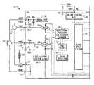
- FIG. 1is a block diagram of an exemplary digital hearing aid system 12 .
- the digital hearing aid system 12includes several external components 14 , 16 , 18 , 20 , 22 , 24 , 26 , 28 , and, preferably, a single integrated circuit (IC) 12 A.
- the external componentsinclude a pair of microphones 24 , 26 , a tele-coil 28 , a volume control potentiometer 24 , a memory-select toggle switch 16 , battery terminals 18 , 22 , and a speaker 20 .
- Soundis received by the pair of microphones 24 , 26 , and converted into electrical signals that are coupled to the FMIC 12 C and RMIC 12 D inputs to the IC 12 A.
- FMICrefers to “front microphone”
- RMICrefers to “rear microphone.”
- the microphones 24 , 26are biased between a regulated voltage output from the RREG and FREG pins 12 B, and the ground nodes FGND 12 F, RGND 12 G.
- the regulated voltage output on FREG and RREGis generated internally to the IC 12 A by regulator 30 .
- the tele-coil 28is a device used in a hearing aid that magnetically couples to a telephone handset and produces an input current that is proportional to the telephone signal. This input current from the tele-coil 28 is coupled into the rear microphone A/D converter 32 B on the IC 12 A when the switch 76 is connected to the “T” input pin 12 E, indicating that the user of the hearing aid is talking on a telephone.
- the tele-coil 28is used to prevent acoustic feedback into the system when talking on the telephone.
- the volume control potentiometer 14is coupled to the volume control input 12 N of the IC. This variable resistor is used to set the volume sensitivity of the digital hearing aid.
- the memory-select toggle switch 16is coupled between the positive voltage supply VB 18 to the IC 12 A and the memory-select input pin 12 L.
- This switch 16is used to toggle the digital hearing aid system 12 between a series of setup configurations.
- the devicemay have been previously programmed for a variety of environmental settings, such as quiet listening, listening to music, a noisy setting, etc.
- the system parameters of the IC 12 Amay have been optimally configured for the particular user.
- the toggle switch 16By repeatedly pressing the toggle switch 16 , the user may then toggle through the various configurations stored in the read-only memory 44 of the IC 12 A.
- the battery terminals 12 K, 12 H of the IC 12 Aare preferably coupled to a single 1.3 volt zinc-air battery. This battery provides the primary power source for the digital hearing aid system.
- the last external componentis the speaker 20 .
- This elementis coupled to the differential outputs at pins 12 J, 12 I of the IC 12 A, and converts the processed digital input signals from the two microphones 24 , 26 into an audible signal for the user of the digital hearing aid system 12 .
- a pair of A/D converters 32 A, 32 Bare coupled between the front and rear microphones 24 , 26 , and the sound processor 38 , and convert the analog input signals into the digital domain for digital processing by the sound processor 38 .
- a single D/A converter 48converts the processed digital signals back into the analog domain for output by the speaker 20 .
- Other system elementsinclude a regulator 30 , a volume control A/D 40 , an interface/system controller 42 , an EEPROM memory 44 , a power-on reset circuit 46 , and a oscillator/system clock 36 .
- the sound processor 38preferably includes a directional processor and headroom expander 50 , a pre-filter 52 , a wide-band twin detector 54 , a band-split filter 56 , a plurality of narrow-band channel processing and twin detectors 58 A- 58 D, a summer 60 , a post filter 62 , a notch filter 64 , a volume control circuit 66 , an automatic gain control output circuit 68 , a peak clipping circuit 70 , a squelch circuit 72 , and a tone generator 74 .
- the sound processor 38processes digital sound as follows. Sound signals input to the front and rear microphones 24 , 26 are coupled to the front and rear A/D converters 32 A, 32 B, which are preferably Sigma-Delta modulators followed by decimation filters that convert the analog sound inputs from the two microphones into a digital equivalent. Note that when a user of the digital hearing aid system is talking on the telephone, the rear A/D converter 32 B is coupled to the tele-coil input “T” 12 E via switch 76 . Both of the front and rear A/D converters 32 A, 32 B are clocked with the output clock signal from the oscillator/system clock 36 (discussed in more detail below). This same output clock signal is also coupled to the sound processor 38 and the D/A converter 48 .
- the front and rear digital sound signals from the two A/D converters 32 A, 32 Bare coupled to the directional processor and headroom expander 50 of the sound processor 38 .
- the rear A/D converter 32 Bis coupled to the processor 50 through switch 75 . In a first position, the switch 75 couples the digital output of the rear A/D converter 32 B to the processor 50 , and in a second position, the switch 75 couples the digital output of the rear A/D converter 32 B to summation block 71 for the purpose of compensating for occlusion.
- Occlusionis the amplification of the users own voice within the ear canal.
- the rear microphonecan be moved inside the ear canal to receive this unwanted signal created by the occlusion effect.
- the occlusion effectis usually reduced in these types of systems by putting a mechanical vent in the hearing aid. This vent, however, can cause an oscillation problem as the speaker signal feeds back to the microphone(s) through the vent aperture.
- Another problem associated with traditional ventingis a reduced low frequency response (leading to reduced sound quality).
- Yet another limitationoccurs when the direct coupling of ambient sounds results in poor directional performance, particularly in the low frequencies.
- the system shown in FIG. 1solves these problems by canceling the unwanted signal received by the rear microphone 26 by feeding back the rear signal from the A/D converter 32 B to summation circuit 71 .
- the summation circuit 71then subtracts the unwanted signal from the processed composite signal to thereby compensate for the occlusion effect.
- An more-detailed occlusion sub-systemis described below with reference to
- the directional processor and headroom expander 50includes a combination of filtering and delay elements that, when applied to the two digital input signals, forms a single, directionally-sensitive response. This directionally-sensitive response is generated such that the gain of the directional processor 50 will be a maximum value for sounds coming from the front microphone 24 and will be a minimum value for sounds coming from the rear microphone 26 .
- the headroom expander portion of the processor 50significantly extends the dynamic range of the A/D conversion, which is very important for high fidelity audio signal processing. It does this by dynamically adjusting the A/D converters 32 A/ 32 B operating points.
- the headroom expander 50adjusts the gain before and after the A/D conversion so that the total gain remains unchanged, but the intrinsic dynamic range of the A/D converter block 32 A/ 32 B is optimized to the level of the signal being processed.
- the headroom expander portion of the processor 50is described below in more detail with reference to FIGS. 4 and 5 .
- the output from the directional processor and headroom expander 50is coupled to a pre-filter 52 , which is a general-purpose filter for pre-conditioning the sound signal prior to any further signal processing steps.
- This “pre-conditioning”can take many forms, and, in combination with corresponding “post-conditioning” in the post filter 62 , can be used to generate special effects that may be suited to only a particular class of users.
- the pre-filter 52could be configured to mimic the transfer function of the user's middle ear, effectively putting the sound signal into the “cochlear domain.”
- Signal processing algorithms to correct a hearing impairment based on, for example, inner hair cell loss and outer hair cell loss,could be applied by the sound processor 38 .
- the post-filter 62could be configured with the inverse response of the pre-filter 52 in order to convert the sound signal back into the “acoustic domain” from the “cochlear domain.”
- the post-filter 62could be configured with the inverse response of the pre-filter 52 in order to convert the sound signal back into the “acoustic domain” from the “cochlear domain.”
- other pre-conditioning/post-conditioning configurations and corresponding signal processing algorithmscould be utilized.
- the pre-conditioned digital sound signalis then coupled to the band-split filter 56 , which preferably includes a bank of filters with variable corner frequencies and pass-band gains. These filters are used to split the single input signal into four distinct frequency bands.
- the four output signals from the band-split filter 56are preferably in-phase so that when they are summed together in block 60 , after channel processing, nulls or peaks in the composite signal (from the summer) are minimized.
- Channel processing of the four distinct frequency bands from the band-split filter 56is accomplished by a plurality of channel processing/twin detector blocks 58 A- 58 D. Although four blocks are shown in FIG. 1 , it should be clear that more than four (or less than four) frequency bands could be generated in the band-split filter 56 , and thus more or less than four channel processing/twin detector blocks 58 may be utilized with the system.
- Each of the channel processing/twin detectors 58 A- 58 Dprovide an automatic gain control (“AGC”) function that provides compression and gain on the particular frequency band (channel) being processed. Compression of the channel signals permits quieter sounds to be amplified at a higher gain than louder sounds, for which the gain is compressed. In this manner, the user of the system can hear the full range of sounds since the circuits 58 A- 58 D compress the full range of normal hearing into the reduced dynamic range of the individual user as a function of the individual user's hearing loss within the particular frequency band of the channel.
- AGCautomatic gain control
- the channel processing blocks 58 A- 58 Dcan be configured to employ a twin detector average detection scheme while compressing the input signals.
- This twin detection schemeincludes both slow and fast attack/release tracking modules that allow for fast response to transients (in the fast tracking module), while preventing annoying pumping of the input signal (in the slow tracking module) that only a fast time constant would produce.
- the outputs of the fast and slow tracking modulesare compared, and the compression slope is then adjusted accordingly.
- the compression ratio, channel gain, lower and upper thresholds (return to linear point), and the fast and slow time constants (of the fast and slow tracking modules)can be independently programmed and saved in memory 44 for each of the plurality of channel processing blocks 58 A- 58 D.
- FIG. 1also shows a communication bus 59 , which may include one or more connections, for coupling the plurality of channel processing blocks 58 A- 58 D.
- This inter-channel communication bus 59can be used to communicate information between the plurality of channel processing blocks 58 A- 58 D such that each channel (frequency band) can take into account the “energy” level (or some other measure) from the other channel processing blocks.
- each channel processing block 58 A- 58 Dwould take into account the “energy” level from the higher frequency channels.
- the “energy” level from the wide-band detector 54may be used by each of the relatively narrow-band channel processing blocks 58 A- 58 D when processing their individual input signals.
- the four channel signalsare summed by summer 60 to form a composite signal.
- This composite signalis then coupled to the post-filter 62 , which may apply a post-processing filter function as discussed above.
- the composite signalis then applied to a notch-filter 64 , that attenuates a narrow band of frequencies that is adjustable in the frequency range where hearing aids tend to oscillate.
- This notch filter 64is used to reduce feedback and prevent unwanted “whistling” of the device.
- the notch filter 64may include a dynamic transfer function that changes the depth of the notch based upon the magnitude of the input signal.
- the composite signalis then coupled to a volume control circuit 66 .
- the volume control circuit 66receives a digital value from the volume control A/D 40 , which indicates the desired volume level set by the user via potentiometer 14 , and uses this stored digital value to set the gain of an included amplifier circuit.
- the composite signalis then coupled to the AGC-output block 68 .
- the AGC-output circuit 68is a high compression ratio, low distortion limiter that is used to prevent pathological signals from causing large scale distorted output signals from the speaker 20 that could be painful and annoying to the user of the device.
- the composite signalis coupled from the AGC-output circuit 68 to a squelch circuit 72 , that performs an expansion on low-level signals below an adjustable threshold.
- the squelch circuit 72uses an output signal from the wide-band detector 54 for this purpose. The expansion of the low-level signals attenuates noise from the microphones and other circuits when the input S/N ratio is small, thus producing a lower noise signal during quiet situations.
- a tone generator block 74is also shown coupled to the squelch circuit 72 , which is included for calibration and testing of the system.
- the output of the squelch circuit 72is coupled to one input of summer 71 .
- the other input to the summer 71is from the output of the rear A/D converter 32 B, when the switch 75 is in the second position.
- These two signalsare summed in summer 71 , and passed along to the interpolator and peak clipping circuit 70 .
- This circuit 70also operates on pathological signals, but it operates almost instantaneously to large peak signals and is high distortion limiting.
- the interpolatorshifts the signal up in frequency as part of the D/A process and then the signal is clipped so that the distortion products do not alias back into the baseband frequency range.
- the output of the interpolator and peak clipping circuit 70is coupled from the sound processor 38 to the D/A H-Bridge 48 .
- This circuit 48converts the digital representation of the input sound signals to a pulse density modulated representation with complimentary outputs. These outputs are coupled off-chip through outputs 12 J, 12 I to the speaker 20 , which low-pass filters the outputs and produces an acoustic analog of the output signals.
- the D/A H-Bridge 48includes an interpolator, a digital Delta-Sigma modulator, and an H-Bridge output stage.
- the D/A H-Bridge 48is also coupled to and receives the clock signal from the oscillator/system clock 36 (described below).
- the interface/system controller 42is coupled between a serial data interface pin 12 M on the IC 12 , and the sound processor 38 . This interface is used to communicate with an external controller for the purpose of setting the parameters of the system. These parameters can be stored on-chip in the EEPROM 44 . If a “black-out” or “brown-out” condition occurs, then the power-on reset circuit 46 can be used to signal the interface/system controller 42 to configure the system into a known state. Such a condition can occur, for example, if the battery fails.
- FIG. 2is a block diagram of an occlusion sub-system for the digital hearing aid system 12 shown in FIG. 1 .
- the occlusion sub-systemincludes a number of components described above with reference to FIG. 1 , including the front and rear microphones 24 , 26 , the front and rear microphone A/D converters 32 A, 32 B, the directional processor and headroom expander 50 , the sound processor 38 , the summation circuit 71 , the peak clipping circuit 70 , the D/A converter 48 , and the speaker 20 .
- the occlusion sub-systemfurther includes a high frequency equalizer 203 , an interpolator 204 , a microphone equalization filter 200 , a loop filter 202 , and a speaker equalization filter 201 .
- the occlusion sub-systemincludes two signal paths: (1) an intended signal received by the front microphone 24 and amplified for the hearing impaired user, and (2) an acoustical occlusion signal originating in the ear canal that is received by the rear microphone 26 and cancelled in a feedback loop by the occlusion sub-system.
- the intended signal received by the front microphoneis converted from the analog to the digital domain with the front microphone A/D converter 32 A.
- the front microphone A/D converter 32 Aincludes an A/D conversion block 206 which converts the signal into the digital domain, and a decimator block 207 which down-samples the signal to achieve a lower-speed, higher-resolution digital signal.
- the decimator block 207may, for example, down-sample the signal by a factor of sixty-four (64).
- the output from the front microphone A/D converter 32 Ais then coupled to the sound processor 38 which amplifies and conditions the signal as described above with reference to FIG. 1 .
- the output from the sound processor 38is filtered by the high frequency equalizer block 203 .
- the characteristics of the high frequency equalizer block 203are described below with reference to FIG. 3 .
- the output from the high frequency equalizer block 203is up-sampled by the interpolator 204 , and coupled as a positive input to the summation circuit 71 .
- the interpolator 204may, for example, up-sample the signal by a factor of four (4).
- the interpolation block 204is included to transform the low-rate signal processing output from the sound processor 38 and high frequency equalizer 203 to a medium-rate signal that may be used for the occlusion cancellation process.
- the acoustical occlusion signal received by the rear microphone 26is similarly converted from the analog to the digital domain with the rear microphone A/D converter 32 B.
- the rear microphone A/D converter 32 Bincludes an A/D conversion block 208 which converts the occlusion signal to the digital domain and a decimator block 209 which down-samples the signal.
- the decimator block 209may, for example, down-sample the occlusion signal by a factor of sixteen (16), resulting in lower-speed, higher-resolution signal characteristics that are desirable for both low power and low noise operation.
- the output from the rear microphone A/D converter 32 Ais coupled to the microphone equalizing circuit 200 which mirrors the magnitude response of the rear microphone 26 and A/D combination in order to yield an overall flat microphone effect that is desirable for optimal performance.
- the output of the microphone equalizing circuit 200is then coupled as a negative input to the summation circuit 71 .
- the output from the summation circuit 71is coupled to the loop filter 202 which filters the signal to the optimal magnitude and phase characteristics necessary for stable closed-loop operation.
- the filter characteristics for the loop filter 202 necessary to obtain a stable closed loop operationare commonly understood by those skilled in the art of control system theory. Ideally, a gain greater than unity gain is desirable to achieve the beneficial results of negative feedback to reduce the occlusion effect.
- the loop gainshould, however, be less than unity when the overall phase response passes through 180 degrees of shift. Otherwise, the overall feedback may become positive, resulting in system instability.
- the output from the loop filter 202is coupled to the speaker equalization filter 201 which flattens the overall transfer function of the Interpolator 70 , D/A 48 and speaker 20 combination. It should be understood, however, that the loop filter 202 and speaker equalization filter 201 could be combined into one filter block, but are separated in this description to improve clarity.
- the output of the speaker equalizer filter 201is then coupled to the speaker 20 through the interpolator/peak clipper 70 and D/A converter 48 , as described above with reference to FIG. 1 .
- the filtered occlusion signal coupled as a negative input to the summation circuit 71produces an overall negative feedback loop when coupled by blocks 202 , 201 , 70 and 48 to the speaker 20 .
- the frequency at which the overall phase response of the occlusion sub-system approaches 180 degrees (zero phase margin)is as high as practically possible.
- Time delays resulting from inherent sample-based mathematical operations used in digital signal processingmay produce excess phase delay.
- the common use of highly oversampled low resolution sigma delta analog to digital (and digital to analog) converters and their associated high-order decimators and interpolatorsmay produce significant group delays leading to less then optimal performance from a system as described herein.
- the illustrated occlusion sub-systemprovides a mixed sample rate solution whereby the low time delay signal processing is performed at a higher sampling rate than the hearing loss compensation algorithms resulting in greatly reduced delays since the decimation and interpolator designs need not be as high order.
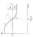
- FIG. 3is a graph 300 showing an exemplary frequency response C for the frequency equalizer block 203 shown in FIG. 2 .
- the frequency response for the frequency equalizer block 203is illustrated as a dotted line labeled “C” on the graph 300 .
- the graph 300assumes ideal speaker and microphone equalization blocks 201 , 200 , such that the speaker and microphone transfer functions can be assumed to be flat (an ideal characteristic).
- Curve A illustrated on the graph 300is a desired frequency response for the loop filter 202 in which the loop filter 202 exhibits greater than unity gain (or 0 dB) at low frequencies, indicating negative feedback and the resultant reduction in the occlusion energy present in the ear canal.
- the open loop gain Areduces, crossing over the unity gain point at a frequency low enough to ensure stability while not unduly reducing the bandwidth over which this system operates (1 KHz for example).
- the closed loop frequency response Bshould be nominally 0 dB up to a frequency roughly equal to the unity gain frequency of the open loop gain A, and then follow the shape of the open loop response A for higher frequencies.
- an overall flat frequency response Dmay be achieved by implementing the filter shape shown as curve C with the high frequency equalizer block 203 . This embodiment results in about 10 dB of boost for frequencies above the transition frequency (1 KHz in this example).
- FIG. 4is a more detailed block diagram of the headroom expander 50 and A/D converters 32 A, 32 B shown in FIG. 1 .
- the front microphone and rear microphone A/D converters 32 A, 32 Binclude a preamplifier 405 , an analog-to-digital conversion block 404 , and a digital-to-analog conversion block 406 .
- the headroom expander 50includes two similar circuits, each circuit including a multiplier 400 , a delay 401 , a threshold/gain control block 402 , and a level detector 403 . Also shown are the front and rear microphones 24 , 26 and a directional processor 410 .
- the headroom expander circuits 400 - 403optimize the operating point of the analog-to-digital converters 404 by adjusting the gain of the preamplifiers 405 in a controlled fashion while adjusting the gain of the multipliers 400 in a correspondingly opposite fashion.
- the overall gain from the input to the A/D converters 32 A, 32 B through to the output of the multipliers 400is substantially independent of the actual gain of the preamplifiers 405 .
- the gain applied by the preamplifiers 405is in the analog domain while the gain adjustment by the multipliers 400 is in the digital domain, thus resulting in a mixed signal compression expander system that increases the effective dynamic range of the analog-to-digital converters 404 .
- the analog signal generated by the front microphone 24is coupled as an input to the preamplifier 405 which applies a variable gain that is controlled by a feedback signal from the threshold and gain control block 402 .
- the amplified output from the preamplifier 405is then converted to the digital domain by the analog-to-digital conversion block 404 .
- the analog-to-digital conversion block 404may, for example, be a Sigma-Delta modulator followed by decimation filters as described above with reference to FIGS. 1 and 2 , or may be some other type of analog-to-digital converter.
- the digital output from the analog-to-digital conversion block 404is coupled as inputs to the multiplier 400 and the level detector 403 .
- the level detector 403determines the magnitude of the output of the analog-to-digital conversion block 404 , and generates an energy level output signal.
- the level detector 403operates similarly to the twin detector 54 described above with reference to FIG. 1 .
- the energy level output signal from the level detector 403is coupled to the threshold and gain control block 402 which determines when the output of the analog-to-digital converter 404 is above a pre-defined level. If the output of the analog-to-digital converter 404 rises above the pre-defined level, then the threshold and gain control block 402 reduces the gain of the preamplifier 405 and proportionally increases the gain of the multiplier 400 .
- the threshold and gain control block 402controls the gain of the preamplifier 405 with a preamplifier control signal 412 that is converted to the analog domain by the digital-to-analog converter 406 .
- the threshold and gain control block 402adjusts the gain by generating an output gain control signal 414 which is delayed by the delay block 401 and is coupled as a second input to the multiplier 400 .
- the delay introduced to the output gain control signal 414 by the delay block 401is pre-selected to match the delay resulting from the process of analog to digital conversion (including any decimation) performed by the analog-to-digital conversion block 404 .
- Exemplary gain adjustments that may be performed by the threshold and gain control block 402are described below with reference to FIGS. 5 a - 5 c.
- the signal from the rear microphone 26is optimized by the rear microphone A/D converter 32 B and the second headroom expander circuit 400 - 403 .
- the outputs from the two multipliers 400are then coupled as inputs to a directional processor 410 .
- the directional processor 410compares the two signals, and generates a directionally-sensitive response such that gain applied by the directional processor 410 has a maximum value for sounds coming from the front microphone 24 and a minimum value for sounds coming from the rear microphone 26 .
- the directional processor 410may, for example, be implemented as a delay sum beamformer, which is a configuration commonly understood by those skilled in the art.
- the directional processor 410may also include a matching filter coupled in series with the delay sum beamformer that filters the signals from the front and rear microphone headroom expander circuits 400 - 403 such that the rear microphone frequency response is substantially the same as the front microphone frequency response.
- FIGS. 5 a - 5 care graphs 500 , 600 , 700 illustrating exemplary gain adjustments that may be performed by the threshold and gain control block 402 shown in FIG. 4 .
- FIG. 5 aillustrates a single-step gain 502
- FIG. 5 billustrates a multi-step gain 602
- FIG. 5 cillustrates a continuous gain 702 .
- the vertical axis on each graph 500 , 600 , 700represents the output of the analog-to-digital conversion block 404 , illustrated as node 407 in FIG. 4 .
- the horizontal axis on each graph 500 , 600 , 700represents the sound pressure level detected by the front and rear microphones 24 , 26 .
- the single-step gain 502 illustrated in FIG. 5 amay be implemented by the threshold and gain control block 402 with only two gain levels for the preamplifier 405 .
- Thisallows the digital-to-analog conversion block 406 to consist of a 1-bit process, and enables the multiplier 400 to be realized with a sign extended shift (requiring less area and power than a true multiplier). For example, left-shifting the digital-to-analog converter output 407 by 3 bits results in multiplication by 18 dB in the digital domain, and could be matched by designing the preamplifiers 405 such that their gains also differ by 18 dB.
- the multi-step gain 602 illustrated in FIG. 5 bimplements an 18 dB gain change in three 6 dB steps. Similar to the single-step gain implementation 500 described above, this implementation 600 enables the multiplier 400 to be realized through simple bit shifting. In addition, this multi-step gain implementation 602 adds hysteresis to the threshold levels of the analog-to-digital converter output 407 . In this manner, gain switching activity is reduced leading to fewer opportunities for audible artifacts.
- the continuous gain 702 illustrated in FIG. 5 crequires the threshold and gain control block 402 to continuously adjust the gain of the preamplifier 405 .
- the preamplifier 405should have a continuously adjustable variable gain and the digital-to-analog converter 406 should have a higher resolution than necessary to implement the embodiments illustrated in FIGS. 5 a and 5 b .
- the multiplier 400should be a full multiplier having resolution greater than the simple arithmetic shifting techniques previously discussed.
Landscapes
- Health & Medical Sciences (AREA)
- General Health & Medical Sciences (AREA)
- Neurosurgery (AREA)
- Otolaryngology (AREA)
- Physics & Mathematics (AREA)
- Engineering & Computer Science (AREA)
- Acoustics & Sound (AREA)
- Signal Processing (AREA)
- Circuit For Audible Band Transducer (AREA)
- Amplifiers (AREA)
Abstract
Description
Claims (15)
Priority Applications (2)
| Application Number | Priority Date | Filing Date | Title |
|---|---|---|---|
| US10/121,221US6937738B2 (en) | 2001-04-12 | 2002-04-12 | Digital hearing aid system |
| US11/150,896US7433481B2 (en) | 2001-04-12 | 2005-06-13 | Digital hearing aid system |
Applications Claiming Priority (2)
| Application Number | Priority Date | Filing Date | Title |
|---|---|---|---|
| US28331001P | 2001-04-12 | 2001-04-12 | |
| US10/121,221US6937738B2 (en) | 2001-04-12 | 2002-04-12 | Digital hearing aid system |
Related Child Applications (1)
| Application Number | Title | Priority Date | Filing Date |
|---|---|---|---|
| US11/150,896ContinuationUS7433481B2 (en) | 2001-04-12 | 2005-06-13 | Digital hearing aid system |
Publications (2)
| Publication Number | Publication Date |
|---|---|
| US20030012391A1 US20030012391A1 (en) | 2003-01-16 |
| US6937738B2true US6937738B2 (en) | 2005-08-30 |
Family
ID=23085430
Family Applications (2)
| Application Number | Title | Priority Date | Filing Date |
|---|---|---|---|
| US10/121,221Expired - LifetimeUS6937738B2 (en) | 2001-04-12 | 2002-04-12 | Digital hearing aid system |
| US11/150,896Expired - LifetimeUS7433481B2 (en) | 2001-04-12 | 2005-06-13 | Digital hearing aid system |
Family Applications After (1)
| Application Number | Title | Priority Date | Filing Date |
|---|---|---|---|
| US11/150,896Expired - LifetimeUS7433481B2 (en) | 2001-04-12 | 2005-06-13 | Digital hearing aid system |
Country Status (3)
| Country | Link |
|---|---|
| US (2) | US6937738B2 (en) |
| EP (1) | EP1251714B2 (en) |
| DK (1) | DK1251714T4 (en) |
Cited By (45)
| Publication number | Priority date | Publication date | Assignee | Title |
|---|---|---|---|---|
| US20030012393A1 (en)* | 2001-04-18 | 2003-01-16 | Armstrong Stephen W. | Digital quasi-RMS detector |
| US20030012392A1 (en)* | 2001-04-18 | 2003-01-16 | Armstrong Stephen W. | Inter-channel communication In a multi-channel digital hearing instrument |
| US20030086581A1 (en)* | 2001-10-12 | 2003-05-08 | Killion Mead C | High fidelity digital hearing aid and methods of programming and operating same |
| US20040190734A1 (en)* | 2002-01-28 | 2004-09-30 | Gn Resound A/S | Binaural compression system |
| US20040240693A1 (en)* | 2003-05-30 | 2004-12-02 | Joyce Rosenthal | Multi-parameter hearing aid |
| US20050195996A1 (en)* | 2004-03-05 | 2005-09-08 | Dunn William F. | Companion microphone system and method |
| US20050232452A1 (en)* | 2001-04-12 | 2005-10-20 | Armstrong Stephen W | Digital hearing aid system |
| US20050244021A1 (en)* | 2004-04-20 | 2005-11-03 | Starkey Laboratories, Inc. | Adjusting and display tool and potentiometer |
| US20050249359A1 (en)* | 2004-04-30 | 2005-11-10 | Phonak Ag | Automatic microphone matching |
| US20060184213A1 (en)* | 2005-02-15 | 2006-08-17 | Griffith Glen A | Integrated phase-shift power control transmitter for use with implantable device and method for use of the same |
| US20070009122A1 (en)* | 2005-07-11 | 2007-01-11 | Volkmar Hamacher | Hearing apparatus and a method for own-voice detection |
| US20070183609A1 (en)* | 2005-12-22 | 2007-08-09 | Jenn Paul C C | Hearing aid system without mechanical and acoustic feedback |
| US7365669B1 (en)* | 2007-03-28 | 2008-04-29 | Cirrus Logic, Inc. | Low-delay signal processing based on highly oversampled digital processing |
| US20080123866A1 (en)* | 2006-11-29 | 2008-05-29 | Rule Elizabeth L | Hearing instrument with acoustic blocker, in-the-ear microphone and speaker |
| US20080144868A1 (en)* | 2006-12-14 | 2008-06-19 | Phonak Ag | Hearing instrument, and a method of operating a hearing instrument |
| US20080226104A1 (en)* | 2007-03-16 | 2008-09-18 | Mark Hedstrom | Wireless handsfree device and hearing aid |
| US20090046867A1 (en)* | 2006-04-12 | 2009-02-19 | Wolfson Microelectronics Plc | Digtal Circuit Arrangements for Ambient Noise-Reduction |
| US20090290739A1 (en)* | 2008-05-21 | 2009-11-26 | Starkey Laboratories, Inc. | Mixing of in-the-ear microphone and outside-the-ear microphone signals to enhance spatial perception |
| US20090299742A1 (en)* | 2008-05-29 | 2009-12-03 | Qualcomm Incorporated | Systems, methods, apparatus, and computer program products for spectral contrast enhancement |
| WO2010034337A1 (en)* | 2008-09-23 | 2010-04-01 | Phonak Ag | Hearing system and method for operating such a system |
| US20100166209A1 (en)* | 2008-12-31 | 2010-07-01 | Etymotic Research, Inc. | Companion microphone system and method |
| US20100239100A1 (en)* | 2009-03-19 | 2010-09-23 | Siemens Medical Instruments Pte. Ltd. | Method for adjusting a directional characteristic and a hearing apparatus |
| US20100266136A1 (en)* | 2009-04-15 | 2010-10-21 | Nokia Corporation | Apparatus, method and computer program |
| US20100272277A1 (en)* | 2009-04-28 | 2010-10-28 | Marcel Joho | Dynamically Configurable ANR Signal Processing Topology |
| US20100272276A1 (en)* | 2009-04-28 | 2010-10-28 | Carreras Ricardo F | ANR Signal Processing Topology |
| US20100272278A1 (en)* | 2009-04-28 | 2010-10-28 | Marcel Joho | Dynamically Configurable ANR Filter Block Topology |
| US20100272282A1 (en)* | 2009-04-28 | 2010-10-28 | Carreras Ricardo F | ANR Settings Triple-Buffering |
| US20100296668A1 (en)* | 2009-04-23 | 2010-11-25 | Qualcomm Incorporated | Systems, methods, apparatus, and computer-readable media for automatic control of active noise cancellation |
| US20110188665A1 (en)* | 2009-04-28 | 2011-08-04 | Burge Benjamin D | Convertible filter |
| EP2434780A1 (en) | 2010-09-22 | 2012-03-28 | GN ReSound A/S | Hearing aid with occlusion suppression and subsonic energy control |
| WO2012104142A1 (en) | 2011-02-01 | 2012-08-09 | Phonak Ag | Hearing device with a transducer module and method for manufacturing a transducer module |
| US8442253B2 (en) | 2011-01-26 | 2013-05-14 | Brainstorm Audio, Llc | Hearing aid |
| US8494201B2 (en) | 2010-09-22 | 2013-07-23 | Gn Resound A/S | Hearing aid with occlusion suppression |
| US8538749B2 (en) | 2008-07-18 | 2013-09-17 | Qualcomm Incorporated | Systems, methods, apparatus, and computer program products for enhanced intelligibility |
| US8594353B2 (en) | 2010-09-22 | 2013-11-26 | Gn Resound A/S | Hearing aid with occlusion suppression and subsonic energy control |
| US9053697B2 (en) | 2010-06-01 | 2015-06-09 | Qualcomm Incorporated | Systems, methods, devices, apparatus, and computer program products for audio equalization |
| US20150222997A1 (en)* | 2014-02-03 | 2015-08-06 | Zhimin FANG | Hearing Aid Devices with Reduced Background and Feedback Noises |
| US9401158B1 (en) | 2015-09-14 | 2016-07-26 | Knowles Electronics, Llc | Microphone signal fusion |
| WO2016115622A1 (en)* | 2015-01-22 | 2016-07-28 | Eers Global Technologies Inc. | Active hearing protection device and method therefore |
| US9467774B2 (en) | 2012-02-10 | 2016-10-11 | Infineon Technologies Ag | System and method for a PCM interface for a capacitive signal source |
| US9779716B2 (en) | 2015-12-30 | 2017-10-03 | Knowles Electronics, Llc | Occlusion reduction and active noise reduction based on seal quality |
| WO2017180533A1 (en)* | 2016-04-11 | 2017-10-19 | Gajstut Enrique | Audio amplification electronic device with independent pitch and bass response adjustment |
| US9812149B2 (en) | 2016-01-28 | 2017-11-07 | Knowles Electronics, Llc | Methods and systems for providing consistency in noise reduction during speech and non-speech periods |
| US9830930B2 (en) | 2015-12-30 | 2017-11-28 | Knowles Electronics, Llc | Voice-enhanced awareness mode |
| EP3588985A1 (en) | 2018-06-28 | 2020-01-01 | GN Hearing A/S | Binaural hearing device system with binaural active occlusion cancellation |
Families Citing this family (65)
| Publication number | Priority date | Publication date | Assignee | Title |
|---|---|---|---|---|
| AU2003247271A1 (en)* | 2002-09-02 | 2004-03-19 | Oticon A/S | Method for counteracting the occlusion effects |
| US7010135B2 (en)* | 2002-10-02 | 2006-03-07 | Phonak Ag | Method to determine a feedback threshold in a hearing device |
| US7536022B2 (en)* | 2002-10-02 | 2009-05-19 | Phonak Ag | Method to determine a feedback threshold in a hearing device |
| EP1448022A1 (en)* | 2003-02-14 | 2004-08-18 | GN ReSound A/S | Dynamic Compression in a hearing aid |
| US7366656B2 (en)* | 2003-02-20 | 2008-04-29 | Ramot At Tel Aviv University Ltd. | Method apparatus and system for processing acoustic signals |
| DE602004020872D1 (en) | 2003-02-25 | 2009-06-10 | Oticon As | T IN A COMMUNICATION DEVICE |
| RU2248106C2 (en)* | 2003-05-12 | 2005-03-10 | Государственное учреждение Санкт-Петербургский научно-исследовательский институт уха, горла, носа и речи МЗ РФ (НИИ ЛОР) | Method for modeling auditory perception in patients after cochlear implantation |
| US20050058313A1 (en)* | 2003-09-11 | 2005-03-17 | Victorian Thomas A. | External ear canal voice detection |
| US20050090295A1 (en)* | 2003-10-14 | 2005-04-28 | Gennum Corporation | Communication headset with signal processing capability |
| KR20050053139A (en)* | 2003-12-02 | 2005-06-08 | 삼성전자주식회사 | Method and apparatus for compensating sound field using peak and dip frequency |
| EP1721488B1 (en)* | 2004-03-03 | 2008-11-05 | Widex A/S | Hearing aid comprising adaptive feedback suppression system |
| WO2006037156A1 (en)* | 2004-10-01 | 2006-04-13 | Hear Works Pty Ltd | Acoustically transparent occlusion reduction system and method |
| US20060211910A1 (en)* | 2005-03-18 | 2006-09-21 | Patrik Westerkull | Microphone system for bone anchored bone conduction hearing aids |
| DE602005016433D1 (en)* | 2005-11-09 | 2009-10-15 | Schwartz Stephan R | Pairwise complementary equalizer |
| JP4359599B2 (en)* | 2006-02-28 | 2009-11-04 | リオン株式会社 | hearing aid |
| US7957548B2 (en)* | 2006-05-16 | 2011-06-07 | Phonak Ag | Hearing device with transfer function adjusted according to predetermined acoustic environments |
| US8199919B2 (en) | 2006-06-01 | 2012-06-12 | Personics Holdings Inc. | Earhealth monitoring system and method II |
| WO2007147077A2 (en) | 2006-06-14 | 2007-12-21 | Personics Holdings Inc. | Earguard monitoring system |
| DE102006029726A1 (en)* | 2006-06-28 | 2008-01-10 | Siemens Audiologische Technik Gmbh | Hearing aid |
| US20100027823A1 (en)* | 2006-10-10 | 2010-02-04 | Georg-Erwin Arndt | Hearing aid having an occlusion reduction unit and method for occlusion reduction |
| JP4882773B2 (en) | 2007-02-05 | 2012-02-22 | ソニー株式会社 | Signal processing apparatus and signal processing method |
| JP4922023B2 (en)* | 2007-03-09 | 2012-04-25 | 株式会社東芝 | Analog-digital conversion device, wireless communication terminal, and program |
| WO2008153588A2 (en)* | 2007-06-01 | 2008-12-18 | Personics Holdings Inc. | Earhealth monitoring system and method iii |
| DK2023664T3 (en)* | 2007-08-10 | 2013-06-03 | Oticon As | Active noise cancellation in hearing aids |
| EP2189006B1 (en)* | 2007-09-20 | 2011-06-29 | Phonak AG | Method for determining of feedback threshold in a hearing device |
| US20110026746A1 (en)* | 2007-09-20 | 2011-02-03 | Phonak Ag | Method for determining of feedback threshold in a hearing device and a hearing device |
| US8238590B2 (en)* | 2008-03-07 | 2012-08-07 | Bose Corporation | Automated audio source control based on audio output device placement detection |
| US8675461B1 (en)* | 2008-08-25 | 2014-03-18 | Marvell International Ltd. | Adjusting a defect threshold |
| DE102009010892B4 (en)* | 2009-02-27 | 2012-06-21 | Siemens Medical Instruments Pte. Ltd. | Apparatus and method for reducing impact sound effects in hearing devices with active occlusion reduction |
| US8699719B2 (en)* | 2009-03-30 | 2014-04-15 | Bose Corporation | Personal acoustic device position determination |
| US8238567B2 (en)* | 2009-03-30 | 2012-08-07 | Bose Corporation | Personal acoustic device position determination |
| US8243946B2 (en)* | 2009-03-30 | 2012-08-14 | Bose Corporation | Personal acoustic device position determination |
| US8238570B2 (en)* | 2009-03-30 | 2012-08-07 | Bose Corporation | Personal acoustic device position determination |
| US9219964B2 (en) | 2009-04-01 | 2015-12-22 | Starkey Laboratories, Inc. | Hearing assistance system with own voice detection |
| US8477973B2 (en) | 2009-04-01 | 2013-07-02 | Starkey Laboratories, Inc. | Hearing assistance system with own voice detection |
| US8532310B2 (en) | 2010-03-30 | 2013-09-10 | Bose Corporation | Frequency-dependent ANR reference sound compression |
| US8611553B2 (en) | 2010-03-30 | 2013-12-17 | Bose Corporation | ANR instability detection |
| US8315405B2 (en)* | 2009-04-28 | 2012-11-20 | Bose Corporation | Coordinated ANR reference sound compression |
| US8472637B2 (en) | 2010-03-30 | 2013-06-25 | Bose Corporation | Variable ANR transform compression |
| US7928886B2 (en)* | 2009-07-01 | 2011-04-19 | Infineon Technologies Ag | Emulation of analog-to-digital converter characteristics |
| DK2302952T3 (en)* | 2009-08-28 | 2012-11-19 | Siemens Medical Instr Pte Ltd | Self-adaptation of a hearing aid |
| JP5424853B2 (en)* | 2009-12-21 | 2014-02-26 | ラピスセミコンダクタ株式会社 | Signal processing apparatus and signal processing method |
| US8923523B2 (en) | 2010-03-25 | 2014-12-30 | King Fahd University Of Petroleum And Minerals | Selective filtering earplugs |
| DK2591615T3 (en)* | 2010-07-05 | 2014-04-22 | Widex As | SYSTEM AND PROCEDURE FOR MEASURING AND VALIDATING THE EFFECTIVE EFFECT OF A HEARING CONSUMER |
| US20120155667A1 (en)* | 2010-12-16 | 2012-06-21 | Nair Vijayakumaran V | Adaptive noise cancellation |
| EP2482566B1 (en)* | 2011-01-28 | 2014-07-16 | Sony Ericsson Mobile Communications AB | Method for generating an audio signal |
| EP2512157B1 (en)* | 2011-04-13 | 2013-11-20 | Oticon A/s | Hearing device with automatic clipping prevention and corresponding method |
| JP2013098691A (en)* | 2011-10-31 | 2013-05-20 | Ricoh Co Ltd | Volume control circuit |
| EP2608569B1 (en) | 2011-12-22 | 2014-07-23 | ST-Ericsson SA | Digital microphone device with extended dynamic range |
| KR101225678B1 (en)* | 2012-09-17 | 2013-01-24 | (주)알고코리아 | Auto-steering directional hearing aid and method of operation thereof |
| US9288584B2 (en) | 2012-09-25 | 2016-03-15 | Gn Resound A/S | Hearing aid for providing phone signals |
| EP2712211B1 (en)* | 2012-09-25 | 2015-09-16 | GN Resound A/S | Hearing aid for providing phone signals |
| US10043535B2 (en)* | 2013-01-15 | 2018-08-07 | Staton Techiya, Llc | Method and device for spectral expansion for an audio signal |
| US9754604B2 (en) | 2013-04-15 | 2017-09-05 | Nuance Communications, Inc. | System and method for addressing acoustic signal reverberation |
| US9084050B2 (en)* | 2013-07-12 | 2015-07-14 | Elwha Llc | Systems and methods for remapping an audio range to a human perceivable range |
| EP2991379B1 (en) | 2014-08-28 | 2017-05-17 | Sivantos Pte. Ltd. | Method and device for improved perception of own voice |
| US9723415B2 (en)* | 2015-06-19 | 2017-08-01 | Gn Hearing A/S | Performance based in situ optimization of hearing aids |
| US9860626B2 (en) | 2016-05-18 | 2018-01-02 | Bose Corporation | On/off head detection of personal acoustic device |
| US9838812B1 (en) | 2016-11-03 | 2017-12-05 | Bose Corporation | On/off head detection of personal acoustic device using an earpiece microphone |
| US11012792B2 (en) | 2017-01-31 | 2021-05-18 | Widex A/S | Method of operating a hearing aid system and a hearing aid system |
| DK201700062A1 (en) | 2017-01-31 | 2018-09-11 | Widex A/S | Method of operating a hearing aid system and a hearing aid system |
| US10511915B2 (en) | 2018-02-08 | 2019-12-17 | Facebook Technologies, Llc | Listening device for mitigating variations between environmental sounds and internal sounds caused by the listening device blocking an ear canal of a user |
| DE102019213810B3 (en) | 2019-09-11 | 2020-11-19 | Sivantos Pte. Ltd. | Method for operating a hearing aid and hearing aid |
| EP3799444B1 (en)* | 2019-09-25 | 2025-04-09 | Oticon A/s | A hearing aid comprising a directional microphone system |
| EP4040801A1 (en)* | 2021-02-09 | 2022-08-10 | Oticon A/s | A hearing aid configured to select a reference microphone |
Citations (102)
| Publication number | Priority date | Publication date | Assignee | Title |
|---|---|---|---|---|
| US4119814A (en) | 1976-12-22 | 1978-10-10 | Siemens Aktiengesellschaft | Hearing aid with adjustable frequency response |
| US4142072A (en) | 1976-11-29 | 1979-02-27 | Oticon Electronics A/S | Directional/omnidirectional hearing aid microphone with support |
| US4187413A (en) | 1977-04-13 | 1980-02-05 | Siemens Aktiengesellschaft | Hearing aid with digital processing for: correlation of signals from plural microphones, dynamic range control, or filtering using an erasable memory |
| US4289935A (en) | 1979-03-08 | 1981-09-15 | Siemens Aktiengesellschaft | Method for generating acoustical voice signals for persons extremely hard of hearing and a device for implementing this method |
| WO1983002212A1 (en) | 1981-12-10 | 1983-06-23 | Bisgaard, Peter, Nikolai | Method and apparatus for adapting the transfer function in a hearing aid |
| US4395588A (en) | 1980-03-18 | 1983-07-26 | U.S. Philips Corporation | MFB system with a by-pass network |
| US4403118A (en) | 1980-04-25 | 1983-09-06 | Siemens Aktiengesellschaft | Method for generating acoustical speech signals which can be understood by persons extremely hard of hearing and a device for the implementation of said method |
| US4455675A (en) | 1982-04-28 | 1984-06-19 | Bose Corporation | Headphoning |
| US4471171A (en) | 1982-02-17 | 1984-09-11 | Robert Bosch Gmbh | Digital hearing aid and method |
| US4494074A (en) | 1982-04-28 | 1985-01-15 | Bose Corporation | Feedback control |
| US4508940A (en) | 1981-08-06 | 1985-04-02 | Siemens Aktiengesellschaft | Device for the compensation of hearing impairments |
| US4592087A (en) | 1983-12-08 | 1986-05-27 | Industrial Research Products, Inc. | Class D hearing aid amplifier |
| US4644581A (en) | 1985-06-27 | 1987-02-17 | Bose Corporation | Headphone with sound pressure sensing means |
| US4689820A (en) | 1982-02-17 | 1987-08-25 | Robert Bosch Gmbh | Hearing aid responsive to signals inside and outside of the audio frequency range |
| US4689818A (en) | 1983-04-28 | 1987-08-25 | Siemens Hearing Instruments, Inc. | Resonant peak control |
| US4696032A (en) | 1985-02-26 | 1987-09-22 | Siemens Corporate Research & Support, Inc. | Voice switched gain system |
| US4712244A (en) | 1985-10-16 | 1987-12-08 | Siemens Aktiengesellschaft | Directional microphone arrangement |
| US4750207A (en) | 1986-03-31 | 1988-06-07 | Siemens Hearing Instruments, Inc. | Hearing aid noise suppression system |
| WO1989004583A1 (en) | 1987-11-12 | 1989-05-18 | Nicolet Instrument Corporation | Adaptive, programmable signal processing hearing aid |
| US4833719A (en) | 1986-03-07 | 1989-05-23 | Centre National De La Recherche Scientifique | Method and apparatus for attentuating external origin noise reaching the eardrum, and for improving intelligibility of electro-acoustic communications |
| US4852175A (en) | 1988-02-03 | 1989-07-25 | Siemens Hearing Instr Inc | Hearing aid signal-processing system |
| US4868880A (en) | 1988-06-01 | 1989-09-19 | Yale University | Method and device for compensating for partial hearing loss |
| US4882762A (en) | 1988-02-23 | 1989-11-21 | Resound Corporation | Multi-band programmable compression system |
| JPH02192300A (en) | 1989-01-19 | 1990-07-30 | Citizen Watch Co Ltd | Digital gain control circuit for hearing aid |
| US4947433A (en) | 1989-03-29 | 1990-08-07 | Siemens Hearing Instruments, Inc. | Circuit for use in programmable hearing aids |
| US4947432A (en) | 1986-02-03 | 1990-08-07 | Topholm & Westermann Aps | Programmable hearing aid |
| US4953216A (en) | 1988-02-01 | 1990-08-28 | Siemens Aktiengesellschaft | Apparatus for the transmission of speech |
| US4953217A (en) | 1987-07-20 | 1990-08-28 | Plessey Overseas Limited | Noise reduction system |
| US4985925A (en) | 1988-06-24 | 1991-01-15 | Sensor Electronics, Inc. | Active noise reduction system |
| US4989251A (en) | 1988-05-10 | 1991-01-29 | Diaphon Development Ab | Hearing aid programming interface and method |
| US4995085A (en) | 1987-10-15 | 1991-02-19 | Siemens Aktiengesellschaft | Hearing aid adaptable for telephone listening |
| US5029217A (en) | 1986-01-21 | 1991-07-02 | Harold Antin | Digital hearing enhancement apparatus |
| US5033082A (en) | 1989-07-31 | 1991-07-16 | Nelson Industries, Inc. | Communication system with active noise cancellation |
| US5033090A (en) | 1988-03-18 | 1991-07-16 | Oticon A/S | Hearing aid, especially of the in-the-ear type |
| US5046102A (en) | 1985-10-16 | 1991-09-03 | Siemens Aktiengesellschaft | Hearing aid with adjustable frequency response |
| US5111419A (en) | 1988-03-23 | 1992-05-05 | Central Institute For The Deaf | Electronic filters, signal conversion apparatus, hearing aids and methods |
| US5144674A (en) | 1988-10-13 | 1992-09-01 | Siemens Aktiengesellschaft | Digital programming device for hearing aids |
| US5189704A (en) | 1990-07-25 | 1993-02-23 | Siemens Aktiengesellschaft | Hearing aid circuit having an output stage with a limiting means |
| US5201006A (en) | 1989-08-22 | 1993-04-06 | Oticon A/S | Hearing aid with feedback compensation |
| US5202927A (en) | 1989-01-11 | 1993-04-13 | Topholm & Westermann Aps | Remote-controllable, programmable, hearing aid system |
| US5210803A (en) | 1990-10-12 | 1993-05-11 | Siemens Aktiengesellschaft | Hearing aid having a data storage |
| US5241310A (en) | 1992-03-02 | 1993-08-31 | General Electric Company | Wide dynamic range delta sigma analog-to-digital converter with precise gain tracking |
| US5247581A (en) | 1991-09-27 | 1993-09-21 | Exar Corporation | Class-d bicmos hearing aid output amplifier |
| US5251263A (en) | 1992-05-22 | 1993-10-05 | Andrea Electronics Corporation | Adaptive noise cancellation and speech enhancement system and apparatus therefor |
| US5267321A (en) | 1991-11-19 | 1993-11-30 | Edwin Langberg | Active sound absorber |
| US5276739A (en) | 1989-11-30 | 1994-01-04 | Nha A/S | Programmable hybrid hearing aid with digital signal processing |
| US5278912A (en) | 1991-06-28 | 1994-01-11 | Resound Corporation | Multiband programmable compression system |
| US5347587A (en) | 1991-11-20 | 1994-09-13 | Sharp Kabushiki Kaisha | Speaker driving device |
| US5376892A (en) | 1993-07-26 | 1994-12-27 | Texas Instruments Incorporated | Sigma delta saturation detector and soft resetting circuit |
| US5389829A (en) | 1991-09-27 | 1995-02-14 | Exar Corporation | Output limiter for class-D BICMOS hearing aid output amplifier |
| WO1995008248A1 (en) | 1993-09-17 | 1995-03-23 | Audiologic, Incorporated | Noise reduction system for binaural hearing aid |
| US5448644A (en) | 1992-06-29 | 1995-09-05 | Siemens Audiologische Technik Gmbh | Hearing aid |
| US5452361A (en) | 1993-06-22 | 1995-09-19 | Noise Cancellation Technologies, Inc. | Reduced VLF overload susceptibility active noise cancellation headset |
| US5479522A (en) | 1993-09-17 | 1995-12-26 | Audiologic, Inc. | Binaural hearing aid |
| US5500902A (en) | 1994-07-08 | 1996-03-19 | Stockham, Jr.; Thomas G. | Hearing aid device incorporating signal processing techniques |
| US5515443A (en) | 1993-06-30 | 1996-05-07 | Siemens Aktiengesellschaft | Interface for serial data trasmission between a hearing aid and a control device |
| US5524150A (en) | 1992-02-27 | 1996-06-04 | Siemens Audiologische Technik Gmbh | Hearing aid providing an information output signal upon selection of an electronically set transmission parameter |
| US5600729A (en) | 1993-01-28 | 1997-02-04 | The Secretary Of State For Defence In Her Britannic Majesty's Government Of The United Kingdom Of Great Britain And Northern Ireland | Ear defenders employing active noise control |
| US5604812A (en) | 1994-05-06 | 1997-02-18 | Siemens Audiologische Technik Gmbh | Programmable hearing aid with automatic adaption to auditory conditions |
| US5608803A (en) | 1993-08-05 | 1997-03-04 | The University Of New Mexico | Programmable digital hearing aid |
| US5613008A (en) | 1992-06-29 | 1997-03-18 | Siemens Audiologische Technik Gmbh | Hearing aid |
| WO1997014266A2 (en) | 1995-10-10 | 1997-04-17 | Audiologic, Inc. | Digital signal processing hearing aid with processing strategy selection |
| US5649019A (en) | 1993-09-13 | 1997-07-15 | Thomasson; Samuel L. | Digital apparatus for reducing acoustic feedback |
| US5661814A (en) | 1993-11-10 | 1997-08-26 | Phonak Ag | Hearing aid apparatus |
| US5687241A (en) | 1993-12-01 | 1997-11-11 | Topholm & Westermann Aps | Circuit arrangement for automatic gain control of hearing aids |
| DE19624092A1 (en) | 1996-05-06 | 1997-11-13 | Siemens Audiologische Technik | Amplification circuit e.g. for analogue or digital hearing aid |
| US5706351A (en) | 1994-03-23 | 1998-01-06 | Siemens Audiologische Technik Gmbh | Programmable hearing aid with fuzzy logic control of transmission characteristics |
| US5710820A (en) | 1994-03-31 | 1998-01-20 | Siemens Augiologische Technik Gmbh | Programmable hearing aid |
| US5717770A (en) | 1994-03-23 | 1998-02-10 | Siemens Audiologische Technik Gmbh | Programmable hearing aid with fuzzy logic control of transmission characteristics |
| US5719528A (en) | 1996-04-23 | 1998-02-17 | Phonak Ag | Hearing aid device |
| US5724433A (en) | 1993-04-07 | 1998-03-03 | K/S Himpp | Adaptive gain and filtering circuit for a sound reproduction system |
| US5740258A (en) | 1995-06-05 | 1998-04-14 | Mcnc | Active noise supressors and methods for use in the ear canal |
| US5740257A (en) | 1996-12-19 | 1998-04-14 | Lucent Technologies Inc. | Active noise control earpiece being compatible with magnetic coupled hearing aids |
| US5754661A (en) | 1994-11-10 | 1998-05-19 | Siemens Audiologische Technik Gmbh | Programmable hearing aid |
| US5796848A (en) | 1995-12-07 | 1998-08-18 | Siemens Audiologische Technik Gmbh | Digital hearing aid |
| US5809151A (en) | 1996-05-06 | 1998-09-15 | Siemens Audiologisch Technik Gmbh | Hearing aid |
| US5815102A (en) | 1996-06-12 | 1998-09-29 | Audiologic, Incorporated | Delta sigma pwm dac to reduce switching |
| US5838806A (en) | 1996-03-27 | 1998-11-17 | Siemens Aktiengesellschaft | Method and circuit for processing data, particularly signal data in a digital programmable hearing aid |
| US5838801A (en) | 1996-12-10 | 1998-11-17 | Nec Corporation | Digital hearing aid |
| US5862238A (en) | 1995-09-11 | 1999-01-19 | Starkey Laboratories, Inc. | Hearing aid having input and output gain compression circuits |
| US5878146A (en) | 1994-11-26 | 1999-03-02 | T.o slashed.pholm & Westermann APS | Hearing aid |
| US5896101A (en) | 1996-09-16 | 1999-04-20 | Audiologic Hearing Systems, L.P. | Wide dynamic range delta sigma A/D converter |
| US5912977A (en) | 1996-03-20 | 1999-06-15 | Siemens Audiologische Technik Gmbh | Distortion suppression in hearing aids with AGC |
| DE19822021A1 (en) | 1998-05-15 | 1999-12-02 | Siemens Audiologische Technik | Hearing aid with automatic microphone tuning |
| US6005954A (en) | 1996-06-21 | 1999-12-21 | Siemens Audiologische Technik Gmbh | Hearing aid having a digitally constructed calculating unit employing fuzzy logic |
| US6044162A (en) | 1996-12-20 | 2000-03-28 | Sonic Innovations, Inc. | Digital hearing aid using differential signal representations |
| US6044163A (en) | 1996-06-21 | 2000-03-28 | Siemens Audiologische Technik Gmbh | Hearing aid having a digitally constructed calculating unit employing a neural structure |
| US6049618A (en) | 1997-06-30 | 2000-04-11 | Siemens Hearing Instruments, Inc. | Hearing aid having input AGC and output AGC |
| US6049617A (en) | 1996-10-23 | 2000-04-11 | Siemens Audiologische Technik Gmbh | Method and circuit for gain control in digital hearing aids |
| US6108431A (en) | 1996-05-01 | 2000-08-22 | Phonak Ag | Loudness limiter |
| US6118878A (en) | 1993-06-23 | 2000-09-12 | Noise Cancellation Technologies, Inc. | Variable gain active noise canceling system with improved residual noise sensing |
| US6175635B1 (en) | 1997-11-12 | 2001-01-16 | Siemens Audiologische Technik Gmbh | Hearing device and method for adjusting audiological/acoustical parameters |
| US6198830B1 (en) | 1997-01-29 | 2001-03-06 | Siemens Audiologische Technik Gmbh | Method and circuit for the amplification of input signals of a hearing aid |
| US6236731B1 (en) | 1997-04-16 | 2001-05-22 | Dspfactory Ltd. | Filterbank structure and method for filtering and separating an information signal into different bands, particularly for audio signal in hearing aids |
| US6240195B1 (en) | 1997-05-16 | 2001-05-29 | Siemens Audiologische Technik Gmbh | Hearing aid with different assemblies for picking up further processing and adjusting an audio signal to the hearing ability of a hearing impaired person |
| US6240192B1 (en) | 1997-04-16 | 2001-05-29 | Dspfactory Ltd. | Apparatus for and method of filtering in an digital hearing aid, including an application specific integrated circuit and a programmable digital signal processor |
| US6272229B1 (en) | 1999-08-03 | 2001-08-07 | Topholm & Westermann Aps | Hearing aid with adaptive matching of microphones |
| US6278786B1 (en) | 1997-07-29 | 2001-08-21 | Telex Communications, Inc. | Active noise cancellation aircraft headset system |
| US20020076073A1 (en) | 2000-12-19 | 2002-06-20 | Taenzer Jon C. | Automatically switched hearing aid communications earpiece |
| US6445799B1 (en) | 1997-04-03 | 2002-09-03 | Gn Resound North America Corporation | Noise cancellation earpiece |
| US20020150269A1 (en) | 2001-04-13 | 2002-10-17 | Topholm & Westermann Aps | Suppression of perceived occlusion |
| US20020164041A1 (en) | 2001-03-27 | 2002-11-07 | Sensimetrics Corporation | Directional receiver for hearing aids |
Family Cites Families (7)
| Publication number | Priority date | Publication date | Assignee | Title |
|---|---|---|---|---|
| US5182774A (en)† | 1990-07-20 | 1993-01-26 | Telex Communications, Inc. | Noise cancellation headset |
| JPH06233389A (en)† | 1993-02-05 | 1994-08-19 | Sony Corp | Hearing aid |
| US5577511A (en)* | 1995-03-29 | 1996-11-26 | Etymotic Research, Inc. | Occlusion meter and associated method for measuring the occlusion of an occluding object in the ear canal of a subject |
| DE69826331T2 (en)† | 1998-11-09 | 2005-02-17 | Widex A/S | METHOD FOR IN-SITU CORRECTING OR ADJUSTING A SIGNAL PROCESSING METHOD IN A HEARING DEVICE WITH THE HELP OF A REFERENCE SIGNAL PROCESSOR |
| DE19935013C1 (en)† | 1999-07-26 | 2000-11-30 | Siemens Audiologische Technik | Digital programmable hearing aid |
| EP1154673B1 (en)† | 2000-05-12 | 2017-02-22 | Oticon A/S | Combining two signals in a hearing aid |
| US6937738B2 (en)* | 2001-04-12 | 2005-08-30 | Gennum Corporation | Digital hearing aid system |
- 2002
- 2002-04-12USUS10/121,221patent/US6937738B2/ennot_activeExpired - Lifetime
- 2002-04-12DKDK02008393.7Tpatent/DK1251714T4/enactive
- 2002-04-12EPEP02008393.7Apatent/EP1251714B2/ennot_activeExpired - Lifetime
- 2005
- 2005-06-13USUS11/150,896patent/US7433481B2/ennot_activeExpired - Lifetime
Patent Citations (105)
| Publication number | Priority date | Publication date | Assignee | Title |
|---|---|---|---|---|
| US4142072A (en) | 1976-11-29 | 1979-02-27 | Oticon Electronics A/S | Directional/omnidirectional hearing aid microphone with support |
| US4119814A (en) | 1976-12-22 | 1978-10-10 | Siemens Aktiengesellschaft | Hearing aid with adjustable frequency response |
| US4187413A (en) | 1977-04-13 | 1980-02-05 | Siemens Aktiengesellschaft | Hearing aid with digital processing for: correlation of signals from plural microphones, dynamic range control, or filtering using an erasable memory |
| US4289935A (en) | 1979-03-08 | 1981-09-15 | Siemens Aktiengesellschaft | Method for generating acoustical voice signals for persons extremely hard of hearing and a device for implementing this method |
| US4395588A (en) | 1980-03-18 | 1983-07-26 | U.S. Philips Corporation | MFB system with a by-pass network |
| US4403118A (en) | 1980-04-25 | 1983-09-06 | Siemens Aktiengesellschaft | Method for generating acoustical speech signals which can be understood by persons extremely hard of hearing and a device for the implementation of said method |
| US4508940A (en) | 1981-08-06 | 1985-04-02 | Siemens Aktiengesellschaft | Device for the compensation of hearing impairments |
| WO1983002212A1 (en) | 1981-12-10 | 1983-06-23 | Bisgaard, Peter, Nikolai | Method and apparatus for adapting the transfer function in a hearing aid |
| US4471171A (en) | 1982-02-17 | 1984-09-11 | Robert Bosch Gmbh | Digital hearing aid and method |
| US4689820A (en) | 1982-02-17 | 1987-08-25 | Robert Bosch Gmbh | Hearing aid responsive to signals inside and outside of the audio frequency range |
| US4494074A (en) | 1982-04-28 | 1985-01-15 | Bose Corporation | Feedback control |
| US4455675A (en) | 1982-04-28 | 1984-06-19 | Bose Corporation | Headphoning |
| US4689818A (en) | 1983-04-28 | 1987-08-25 | Siemens Hearing Instruments, Inc. | Resonant peak control |
| US4592087B1 (en) | 1983-12-08 | 1996-08-13 | Knowles Electronics Inc | Class D hearing aid amplifier |
| US4592087A (en) | 1983-12-08 | 1986-05-27 | Industrial Research Products, Inc. | Class D hearing aid amplifier |
| US4696032A (en) | 1985-02-26 | 1987-09-22 | Siemens Corporate Research & Support, Inc. | Voice switched gain system |
| US4644581A (en) | 1985-06-27 | 1987-02-17 | Bose Corporation | Headphone with sound pressure sensing means |
| US4712244A (en) | 1985-10-16 | 1987-12-08 | Siemens Aktiengesellschaft | Directional microphone arrangement |
| US5046102A (en) | 1985-10-16 | 1991-09-03 | Siemens Aktiengesellschaft | Hearing aid with adjustable frequency response |
| US5029217A (en) | 1986-01-21 | 1991-07-02 | Harold Antin | Digital hearing enhancement apparatus |
| US4947432B1 (en) | 1986-02-03 | 1993-03-09 | Programmable hearing aid | |
| US4947432A (en) | 1986-02-03 | 1990-08-07 | Topholm & Westermann Aps | Programmable hearing aid |
| US4833719A (en) | 1986-03-07 | 1989-05-23 | Centre National De La Recherche Scientifique | Method and apparatus for attentuating external origin noise reaching the eardrum, and for improving intelligibility of electro-acoustic communications |
| US4750207A (en) | 1986-03-31 | 1988-06-07 | Siemens Hearing Instruments, Inc. | Hearing aid noise suppression system |
| US4953217A (en) | 1987-07-20 | 1990-08-28 | Plessey Overseas Limited | Noise reduction system |
| US4995085A (en) | 1987-10-15 | 1991-02-19 | Siemens Aktiengesellschaft | Hearing aid adaptable for telephone listening |
| WO1989004583A1 (en) | 1987-11-12 | 1989-05-18 | Nicolet Instrument Corporation | Adaptive, programmable signal processing hearing aid |
| US4953216A (en) | 1988-02-01 | 1990-08-28 | Siemens Aktiengesellschaft | Apparatus for the transmission of speech |
| US4852175A (en) | 1988-02-03 | 1989-07-25 | Siemens Hearing Instr Inc | Hearing aid signal-processing system |
| US4882762A (en) | 1988-02-23 | 1989-11-21 | Resound Corporation | Multi-band programmable compression system |
| US5033090A (en) | 1988-03-18 | 1991-07-16 | Oticon A/S | Hearing aid, especially of the in-the-ear type |
| US5111419A (en) | 1988-03-23 | 1992-05-05 | Central Institute For The Deaf | Electronic filters, signal conversion apparatus, hearing aids and methods |
| US4989251A (en) | 1988-05-10 | 1991-01-29 | Diaphon Development Ab | Hearing aid programming interface and method |
| US4868880A (en) | 1988-06-01 | 1989-09-19 | Yale University | Method and device for compensating for partial hearing loss |
| US4985925A (en) | 1988-06-24 | 1991-01-15 | Sensor Electronics, Inc. | Active noise reduction system |
| US5144674A (en) | 1988-10-13 | 1992-09-01 | Siemens Aktiengesellschaft | Digital programming device for hearing aids |
| US5202927A (en) | 1989-01-11 | 1993-04-13 | Topholm & Westermann Aps | Remote-controllable, programmable, hearing aid system |
| JPH02192300A (en) | 1989-01-19 | 1990-07-30 | Citizen Watch Co Ltd | Digital gain control circuit for hearing aid |
| US4947433A (en) | 1989-03-29 | 1990-08-07 | Siemens Hearing Instruments, Inc. | Circuit for use in programmable hearing aids |
| US5033082A (en) | 1989-07-31 | 1991-07-16 | Nelson Industries, Inc. | Communication system with active noise cancellation |
| US5201006A (en) | 1989-08-22 | 1993-04-06 | Oticon A/S | Hearing aid with feedback compensation |
| US5276739A (en) | 1989-11-30 | 1994-01-04 | Nha A/S | Programmable hybrid hearing aid with digital signal processing |
| US5189704A (en) | 1990-07-25 | 1993-02-23 | Siemens Aktiengesellschaft | Hearing aid circuit having an output stage with a limiting means |
| US5210803A (en) | 1990-10-12 | 1993-05-11 | Siemens Aktiengesellschaft | Hearing aid having a data storage |
| US5278912A (en) | 1991-06-28 | 1994-01-11 | Resound Corporation | Multiband programmable compression system |
| US5247581A (en) | 1991-09-27 | 1993-09-21 | Exar Corporation | Class-d bicmos hearing aid output amplifier |
| US5389829A (en) | 1991-09-27 | 1995-02-14 | Exar Corporation | Output limiter for class-D BICMOS hearing aid output amplifier |
| US5267321A (en) | 1991-11-19 | 1993-11-30 | Edwin Langberg | Active sound absorber |
| US5347587A (en) | 1991-11-20 | 1994-09-13 | Sharp Kabushiki Kaisha | Speaker driving device |
| US5524150A (en) | 1992-02-27 | 1996-06-04 | Siemens Audiologische Technik Gmbh | Hearing aid providing an information output signal upon selection of an electronically set transmission parameter |
| US5241310A (en) | 1992-03-02 | 1993-08-31 | General Electric Company | Wide dynamic range delta sigma analog-to-digital converter with precise gain tracking |
| US5251263A (en) | 1992-05-22 | 1993-10-05 | Andrea Electronics Corporation | Adaptive noise cancellation and speech enhancement system and apparatus therefor |
| US5613008A (en) | 1992-06-29 | 1997-03-18 | Siemens Audiologische Technik Gmbh | Hearing aid |
| US5448644A (en) | 1992-06-29 | 1995-09-05 | Siemens Audiologische Technik Gmbh | Hearing aid |
| US5600729A (en) | 1993-01-28 | 1997-02-04 | The Secretary Of State For Defence In Her Britannic Majesty's Government Of The United Kingdom Of Great Britain And Northern Ireland | Ear defenders employing active noise control |
| US5724433A (en) | 1993-04-07 | 1998-03-03 | K/S Himpp | Adaptive gain and filtering circuit for a sound reproduction system |
| US5452361A (en) | 1993-06-22 | 1995-09-19 | Noise Cancellation Technologies, Inc. | Reduced VLF overload susceptibility active noise cancellation headset |
| US6118878A (en) | 1993-06-23 | 2000-09-12 | Noise Cancellation Technologies, Inc. | Variable gain active noise canceling system with improved residual noise sensing |
| US5515443A (en) | 1993-06-30 | 1996-05-07 | Siemens Aktiengesellschaft | Interface for serial data trasmission between a hearing aid and a control device |
| US5376892A (en) | 1993-07-26 | 1994-12-27 | Texas Instruments Incorporated | Sigma delta saturation detector and soft resetting circuit |
| US5608803A (en) | 1993-08-05 | 1997-03-04 | The University Of New Mexico | Programmable digital hearing aid |
| US5649019A (en) | 1993-09-13 | 1997-07-15 | Thomasson; Samuel L. | Digital apparatus for reducing acoustic feedback |
| US5479522A (en) | 1993-09-17 | 1995-12-26 | Audiologic, Inc. | Binaural hearing aid |
| WO1995008248A1 (en) | 1993-09-17 | 1995-03-23 | Audiologic, Incorporated | Noise reduction system for binaural hearing aid |
| US5661814A (en) | 1993-11-10 | 1997-08-26 | Phonak Ag | Hearing aid apparatus |
| US5687241A (en) | 1993-12-01 | 1997-11-11 | Topholm & Westermann Aps | Circuit arrangement for automatic gain control of hearing aids |
| US5706351A (en) | 1994-03-23 | 1998-01-06 | Siemens Audiologische Technik Gmbh | Programmable hearing aid with fuzzy logic control of transmission characteristics |
| US5717770A (en) | 1994-03-23 | 1998-02-10 | Siemens Audiologische Technik Gmbh | Programmable hearing aid with fuzzy logic control of transmission characteristics |
| US5710820A (en) | 1994-03-31 | 1998-01-20 | Siemens Augiologische Technik Gmbh | Programmable hearing aid |
| US5604812A (en) | 1994-05-06 | 1997-02-18 | Siemens Audiologische Technik Gmbh | Programmable hearing aid with automatic adaption to auditory conditions |
| US5500902A (en) | 1994-07-08 | 1996-03-19 | Stockham, Jr.; Thomas G. | Hearing aid device incorporating signal processing techniques |
| US5848171A (en) | 1994-07-08 | 1998-12-08 | Sonix Technologies, Inc. | Hearing aid device incorporating signal processing techniques |
| US5754661A (en) | 1994-11-10 | 1998-05-19 | Siemens Audiologische Technik Gmbh | Programmable hearing aid |
| US5878146A (en) | 1994-11-26 | 1999-03-02 | T.o slashed.pholm & Westermann APS | Hearing aid |
| US5740258A (en) | 1995-06-05 | 1998-04-14 | Mcnc | Active noise supressors and methods for use in the ear canal |
| US5862238A (en) | 1995-09-11 | 1999-01-19 | Starkey Laboratories, Inc. | Hearing aid having input and output gain compression circuits |
| WO1997014266A2 (en) | 1995-10-10 | 1997-04-17 | Audiologic, Inc. | Digital signal processing hearing aid with processing strategy selection |
| US5796848A (en) | 1995-12-07 | 1998-08-18 | Siemens Audiologische Technik Gmbh | Digital hearing aid |
| US5912977A (en) | 1996-03-20 | 1999-06-15 | Siemens Audiologische Technik Gmbh | Distortion suppression in hearing aids with AGC |
| US5838806A (en) | 1996-03-27 | 1998-11-17 | Siemens Aktiengesellschaft | Method and circuit for processing data, particularly signal data in a digital programmable hearing aid |
| US5719528A (en) | 1996-04-23 | 1998-02-17 | Phonak Ag | Hearing aid device |
| US6108431A (en) | 1996-05-01 | 2000-08-22 | Phonak Ag | Loudness limiter |
| US5809151A (en) | 1996-05-06 | 1998-09-15 | Siemens Audiologisch Technik Gmbh | Hearing aid |
| DE19624092A1 (en) | 1996-05-06 | 1997-11-13 | Siemens Audiologische Technik | Amplification circuit e.g. for analogue or digital hearing aid |
| US5815102A (en) | 1996-06-12 | 1998-09-29 | Audiologic, Incorporated | Delta sigma pwm dac to reduce switching |
| US6005954A (en) | 1996-06-21 | 1999-12-21 | Siemens Audiologische Technik Gmbh | Hearing aid having a digitally constructed calculating unit employing fuzzy logic |
| US6044163A (en) | 1996-06-21 | 2000-03-28 | Siemens Audiologische Technik Gmbh | Hearing aid having a digitally constructed calculating unit employing a neural structure |
| US5896101A (en) | 1996-09-16 | 1999-04-20 | Audiologic Hearing Systems, L.P. | Wide dynamic range delta sigma A/D converter |
| US6049617A (en) | 1996-10-23 | 2000-04-11 | Siemens Audiologische Technik Gmbh | Method and circuit for gain control in digital hearing aids |
| US5838801A (en) | 1996-12-10 | 1998-11-17 | Nec Corporation | Digital hearing aid |
| US5740257A (en) | 1996-12-19 | 1998-04-14 | Lucent Technologies Inc. | Active noise control earpiece being compatible with magnetic coupled hearing aids |
| US6044162A (en) | 1996-12-20 | 2000-03-28 | Sonic Innovations, Inc. | Digital hearing aid using differential signal representations |
| US6198830B1 (en) | 1997-01-29 | 2001-03-06 | Siemens Audiologische Technik Gmbh | Method and circuit for the amplification of input signals of a hearing aid |
| US6445799B1 (en) | 1997-04-03 | 2002-09-03 | Gn Resound North America Corporation | Noise cancellation earpiece |
| US6240192B1 (en) | 1997-04-16 | 2001-05-29 | Dspfactory Ltd. | Apparatus for and method of filtering in an digital hearing aid, including an application specific integrated circuit and a programmable digital signal processor |
| US6236731B1 (en) | 1997-04-16 | 2001-05-22 | Dspfactory Ltd. | Filterbank structure and method for filtering and separating an information signal into different bands, particularly for audio signal in hearing aids |
| US6240195B1 (en) | 1997-05-16 | 2001-05-29 | Siemens Audiologische Technik Gmbh | Hearing aid with different assemblies for picking up further processing and adjusting an audio signal to the hearing ability of a hearing impaired person |
| US6049618A (en) | 1997-06-30 | 2000-04-11 | Siemens Hearing Instruments, Inc. | Hearing aid having input AGC and output AGC |
| US6278786B1 (en) | 1997-07-29 | 2001-08-21 | Telex Communications, Inc. | Active noise cancellation aircraft headset system |
| US6175635B1 (en) | 1997-11-12 | 2001-01-16 | Siemens Audiologische Technik Gmbh | Hearing device and method for adjusting audiological/acoustical parameters |
| DE19822021A1 (en) | 1998-05-15 | 1999-12-02 | Siemens Audiologische Technik | Hearing aid with automatic microphone tuning |
| US6272229B1 (en) | 1999-08-03 | 2001-08-07 | Topholm & Westermann Aps | Hearing aid with adaptive matching of microphones |
| US20020076073A1 (en) | 2000-12-19 | 2002-06-20 | Taenzer Jon C. | Automatically switched hearing aid communications earpiece |
| US20020164041A1 (en) | 2001-03-27 | 2002-11-07 | Sensimetrics Corporation | Directional receiver for hearing aids |
| US20020150269A1 (en) | 2001-04-13 | 2002-10-17 | Topholm & Westermann Aps | Suppression of perceived occlusion |
Non-Patent Citations (2)
| Title |
|---|
| Lee, Jo-Hong and Kang, Wen-Juh, "Filter Design for Polyphase Filter Banks with Arbitrary Number of Subband Channels", Department of Electrical Engineering, National Taiwan University, Taipei, Taiwan, Republic of China, pp. 1720-1723. |
| Lunner, Thomas and Hellgren, Johan, "A Digital Filterbank Hearing Aid-Design, Implementation and Evaluation", Department of Electronic Engineering and Department of Otorhinolaryngology, University of Linkoping, Sweden, pp. 3661-3664. |
Cited By (84)
| Publication number | Priority date | Publication date | Assignee | Title |
|---|---|---|---|---|
| US7433481B2 (en)* | 2001-04-12 | 2008-10-07 | Sound Design Technologies, Ltd. | Digital hearing aid system |
| US20050232452A1 (en)* | 2001-04-12 | 2005-10-20 | Armstrong Stephen W | Digital hearing aid system |
| US20030012393A1 (en)* | 2001-04-18 | 2003-01-16 | Armstrong Stephen W. | Digital quasi-RMS detector |
| US20030012392A1 (en)* | 2001-04-18 | 2003-01-16 | Armstrong Stephen W. | Inter-channel communication In a multi-channel digital hearing instrument |
| US7076073B2 (en) | 2001-04-18 | 2006-07-11 | Gennum Corporation | Digital quasi-RMS detector |
| US7181034B2 (en) | 2001-04-18 | 2007-02-20 | Gennum Corporation | Inter-channel communication in a multi-channel digital hearing instrument |
| US8121323B2 (en) | 2001-04-18 | 2012-02-21 | Semiconductor Components Industries, Llc | Inter-channel communication in a multi-channel digital hearing instrument |
| US20030086581A1 (en)* | 2001-10-12 | 2003-05-08 | Killion Mead C | High fidelity digital hearing aid and methods of programming and operating same |
| US7697705B2 (en)* | 2001-10-12 | 2010-04-13 | Etymotic Research, Inc. | High fidelity digital hearing aid and methods of programming and operating same |
| US20040190734A1 (en)* | 2002-01-28 | 2004-09-30 | Gn Resound A/S | Binaural compression system |
| US7630507B2 (en)* | 2002-01-28 | 2009-12-08 | Gn Resound A/S | Binaural compression system |
| US7184564B2 (en)* | 2003-05-30 | 2007-02-27 | Starkey Laboratories, Inc. | Multi-parameter hearing aid |
| US20040240693A1 (en)* | 2003-05-30 | 2004-12-02 | Joyce Rosenthal | Multi-parameter hearing aid |
| US20050195996A1 (en)* | 2004-03-05 | 2005-09-08 | Dunn William F. | Companion microphone system and method |
| US8019386B2 (en)* | 2004-03-05 | 2011-09-13 | Etymotic Research, Inc. | Companion microphone system and method |
| US20050244021A1 (en)* | 2004-04-20 | 2005-11-03 | Starkey Laboratories, Inc. | Adjusting and display tool and potentiometer |
| US7668328B2 (en) | 2004-04-20 | 2010-02-23 | Starkey Laboratories, Inc. | Adjusting and display tool and potentiometer |
| US7688985B2 (en)* | 2004-04-30 | 2010-03-30 | Phonak Ag | Automatic microphone matching |
| US20050249359A1 (en)* | 2004-04-30 | 2005-11-10 | Phonak Ag | Automatic microphone matching |
| US8027732B2 (en)* | 2005-02-15 | 2011-09-27 | Advanced Bionics, Llc | Integrated phase-shift power control transmitter for use with implantable device and method for use of the same |
| US20060184213A1 (en)* | 2005-02-15 | 2006-08-17 | Griffith Glen A | Integrated phase-shift power control transmitter for use with implantable device and method for use of the same |
| US20070009122A1 (en)* | 2005-07-11 | 2007-01-11 | Volkmar Hamacher | Hearing apparatus and a method for own-voice detection |
| US7853031B2 (en) | 2005-07-11 | 2010-12-14 | Siemens Audiologische Technik Gmbh | Hearing apparatus and a method for own-voice detection |
| US20070183609A1 (en)* | 2005-12-22 | 2007-08-09 | Jenn Paul C C | Hearing aid system without mechanical and acoustic feedback |
| US10818281B2 (en) | 2006-04-12 | 2020-10-27 | Cirrus Logic, Inc. | Digital circuit arrangements for ambient noise-reduction |
| CN101385387B (en)* | 2006-04-12 | 2012-08-29 | 沃福森微电子股份有限公司 | Digital circuit arrangements for ambient noise-reduction |
| US20090046867A1 (en)* | 2006-04-12 | 2009-02-19 | Wolfson Microelectronics Plc | Digtal Circuit Arrangements for Ambient Noise-Reduction |
| US8165312B2 (en)* | 2006-04-12 | 2012-04-24 | Wolfson Microelectronics Plc | Digital circuit arrangements for ambient noise-reduction |
| US9558729B2 (en) | 2006-04-12 | 2017-01-31 | Cirrus Logic, Inc. | Digital circuit arrangements for ambient noise-reduction |
| US20170103746A1 (en)* | 2006-04-12 | 2017-04-13 | Cirrus Logic International Semiconductor Ltd. | Digital circuit arrangements for ambient noise-reduction |
| US10319361B2 (en) | 2006-04-12 | 2019-06-11 | Cirrus Logic, Inc. | Digital circuit arrangements for ambient noise-reduction |
| US8644523B2 (en) | 2006-04-12 | 2014-02-04 | Wolfson Microelectronics Plc | Digital circuit arrangements for ambient noise-reduction |
| WO2008064453A1 (en)* | 2006-11-29 | 2008-06-05 | Gennum Corporation | Hearing instrument with acoustic blocker, in-the-ear microphone and speaker |
| US20080123866A1 (en)* | 2006-11-29 | 2008-05-29 | Rule Elizabeth L | Hearing instrument with acoustic blocker, in-the-ear microphone and speaker |
| US20080144868A1 (en)* | 2006-12-14 | 2008-06-19 | Phonak Ag | Hearing instrument, and a method of operating a hearing instrument |
| US8014548B2 (en) | 2006-12-14 | 2011-09-06 | Phonak Ag | Hearing instrument, and a method of operating a hearing instrument |
| US20080226104A1 (en)* | 2007-03-16 | 2008-09-18 | Mark Hedstrom | Wireless handsfree device and hearing aid |
| US7365669B1 (en)* | 2007-03-28 | 2008-04-29 | Cirrus Logic, Inc. | Low-delay signal processing based on highly oversampled digital processing |
| US9161137B2 (en) | 2008-05-21 | 2015-10-13 | Starkey Laboratories, Inc. | Mixing of in-the-ear microphone and outside-the-ear microphone signals to enhance spatial perception |
| US20090290739A1 (en)* | 2008-05-21 | 2009-11-26 | Starkey Laboratories, Inc. | Mixing of in-the-ear microphone and outside-the-ear microphone signals to enhance spatial perception |
| US8107654B2 (en) | 2008-05-21 | 2012-01-31 | Starkey Laboratories, Inc | Mixing of in-the-ear microphone and outside-the-ear microphone signals to enhance spatial perception |
| US8718302B2 (en) | 2008-05-21 | 2014-05-06 | Starkey Laboratories, Inc. | Mixing of in-the-ear microphone and outside-the-ear microphone signals to enhance spatial perception |
| US20090299742A1 (en)* | 2008-05-29 | 2009-12-03 | Qualcomm Incorporated | Systems, methods, apparatus, and computer program products for spectral contrast enhancement |
| US8831936B2 (en) | 2008-05-29 | 2014-09-09 | Qualcomm Incorporated | Systems, methods, apparatus, and computer program products for speech signal processing using spectral contrast enhancement |
| US8538749B2 (en) | 2008-07-18 | 2013-09-17 | Qualcomm Incorporated | Systems, methods, apparatus, and computer program products for enhanced intelligibility |
| WO2010034337A1 (en)* | 2008-09-23 | 2010-04-01 | Phonak Ag | Hearing system and method for operating such a system |
| US20100166209A1 (en)* | 2008-12-31 | 2010-07-01 | Etymotic Research, Inc. | Companion microphone system and method |
| US8150057B2 (en) | 2008-12-31 | 2012-04-03 | Etymotic Research, Inc. | Companion microphone system and method |
| US20100239100A1 (en)* | 2009-03-19 | 2010-09-23 | Siemens Medical Instruments Pte. Ltd. | Method for adjusting a directional characteristic and a hearing apparatus |
| US20100266136A1 (en)* | 2009-04-15 | 2010-10-21 | Nokia Corporation | Apparatus, method and computer program |
| US8477957B2 (en) | 2009-04-15 | 2013-07-02 | Nokia Corporation | Apparatus, method and computer program |
| US9202456B2 (en) | 2009-04-23 | 2015-12-01 | Qualcomm Incorporated | Systems, methods, apparatus, and computer-readable media for automatic control of active noise cancellation |
| US20100296668A1 (en)* | 2009-04-23 | 2010-11-25 | Qualcomm Incorporated | Systems, methods, apparatus, and computer-readable media for automatic control of active noise cancellation |
| US8073151B2 (en) | 2009-04-28 | 2011-12-06 | Bose Corporation | Dynamically configurable ANR filter block topology |
| US20100272278A1 (en)* | 2009-04-28 | 2010-10-28 | Marcel Joho | Dynamically Configurable ANR Filter Block Topology |
| US20100272277A1 (en)* | 2009-04-28 | 2010-10-28 | Marcel Joho | Dynamically Configurable ANR Signal Processing Topology |
| US20100272276A1 (en)* | 2009-04-28 | 2010-10-28 | Carreras Ricardo F | ANR Signal Processing Topology |
| US20100272282A1 (en)* | 2009-04-28 | 2010-10-28 | Carreras Ricardo F | ANR Settings Triple-Buffering |
| US8184822B2 (en)* | 2009-04-28 | 2012-05-22 | Bose Corporation | ANR signal processing topology |
| US20110188665A1 (en)* | 2009-04-28 | 2011-08-04 | Burge Benjamin D | Convertible filter |
| US8165313B2 (en) | 2009-04-28 | 2012-04-24 | Bose Corporation | ANR settings triple-buffering |
| US8073150B2 (en) | 2009-04-28 | 2011-12-06 | Bose Corporation | Dynamically configurable ANR signal processing topology |
| US8090114B2 (en) | 2009-04-28 | 2012-01-03 | Bose Corporation | Convertible filter |
| US8355513B2 (en) | 2009-04-28 | 2013-01-15 | Burge Benjamin D | Convertible filter |
| US9053697B2 (en) | 2010-06-01 | 2015-06-09 | Qualcomm Incorporated | Systems, methods, devices, apparatus, and computer program products for audio equalization |
| EP2434780A1 (en) | 2010-09-22 | 2012-03-28 | GN ReSound A/S | Hearing aid with occlusion suppression and subsonic energy control |
| US8594353B2 (en) | 2010-09-22 | 2013-11-26 | Gn Resound A/S | Hearing aid with occlusion suppression and subsonic energy control |
| US8494201B2 (en) | 2010-09-22 | 2013-07-23 | Gn Resound A/S | Hearing aid with occlusion suppression |
| US9332356B2 (en) | 2011-01-26 | 2016-05-03 | Brainstorm Audio, Llc | Hearing aid |
| US8442253B2 (en) | 2011-01-26 | 2013-05-14 | Brainstorm Audio, Llc | Hearing aid |
| US9571943B2 (en) | 2011-02-01 | 2017-02-14 | Sonova Ag | Hearing device with a transducer module and method for manufacturing a transducer module |
| WO2012104142A1 (en) | 2011-02-01 | 2012-08-09 | Phonak Ag | Hearing device with a transducer module and method for manufacturing a transducer module |
| US9467774B2 (en) | 2012-02-10 | 2016-10-11 | Infineon Technologies Ag | System and method for a PCM interface for a capacitive signal source |
| US9232322B2 (en)* | 2014-02-03 | 2016-01-05 | Zhimin FANG | Hearing aid devices with reduced background and feedback noises |
| US20150222997A1 (en)* | 2014-02-03 | 2015-08-06 | Zhimin FANG | Hearing Aid Devices with Reduced Background and Feedback Noises |
| WO2016115622A1 (en)* | 2015-01-22 | 2016-07-28 | Eers Global Technologies Inc. | Active hearing protection device and method therefore |
| US10238546B2 (en) | 2015-01-22 | 2019-03-26 | Eers Global Technologies Inc. | Active hearing protection device and method therefore |
| US9961443B2 (en) | 2015-09-14 | 2018-05-01 | Knowles Electronics, Llc | Microphone signal fusion |
| US9401158B1 (en) | 2015-09-14 | 2016-07-26 | Knowles Electronics, Llc | Microphone signal fusion |
| US9779716B2 (en) | 2015-12-30 | 2017-10-03 | Knowles Electronics, Llc | Occlusion reduction and active noise reduction based on seal quality |
| US9830930B2 (en) | 2015-12-30 | 2017-11-28 | Knowles Electronics, Llc | Voice-enhanced awareness mode |
| US9812149B2 (en) | 2016-01-28 | 2017-11-07 | Knowles Electronics, Llc | Methods and systems for providing consistency in noise reduction during speech and non-speech periods |
| WO2017180533A1 (en)* | 2016-04-11 | 2017-10-19 | Gajstut Enrique | Audio amplification electronic device with independent pitch and bass response adjustment |
| EP3588985A1 (en) | 2018-06-28 | 2020-01-01 | GN Hearing A/S | Binaural hearing device system with binaural active occlusion cancellation |
Also Published As
| Publication number | Publication date |
|---|---|
| DK1251714T4 (en) | 2015-07-20 |
| EP1251714B2 (en) | 2015-06-03 |
| US20030012391A1 (en) | 2003-01-16 |
| US7433481B2 (en) | 2008-10-07 |
| EP1251714A2 (en) | 2002-10-23 |
| EP1251714B1 (en) | 2011-10-05 |
| DK1251714T3 (en) | 2011-11-21 |
| US20050232452A1 (en) | 2005-10-20 |
| EP1251714A3 (en) | 2004-08-04 |
Similar Documents
| Publication | Publication Date | Title |
|---|---|---|
| US6937738B2 (en) | Digital hearing aid system | |
| US8121323B2 (en) | Inter-channel communication in a multi-channel digital hearing instrument | |
| CA2420989C (en) | Low-noise directional microphone system | |
| EP0770316B1 (en) | Hearing aid device incorporating signal processing techniques | |
| US6072885A (en) | Hearing aid device incorporating signal processing techniques | |
| EP1121834B1 (en) | Hearing aids based on models of cochlear compression | |
| US5396560A (en) | Hearing aid incorporating a novelty filter | |
| US6885752B1 (en) | Hearing aid device incorporating signal processing techniques | |
| US7305100B2 (en) | Dynamic compression in a hearing aid | |
| US20050090295A1 (en) | Communication headset with signal processing capability | |
| US20040202333A1 (en) | Hearing instrument with self-diagnostics | |
| US7076073B2 (en) | Digital quasi-RMS detector | |
| EP1251716B1 (en) | In-situ transducer modeling in a digital hearing instrument | |
| CA2381516C (en) | Digital hearing aid system | |
| CA2582648C (en) | Digital hearing aid system | |
| AU2005203487A1 (en) | Hearing aid device incorporating signal processing techniques |
Legal Events
| Date | Code | Title | Description |
|---|---|---|---|
| AS | Assignment | Owner name:GENNUM CORPORATION, CANADA Free format text:ASSIGNMENT OF ASSIGNORS INTEREST;ASSIGNORS:ARMSTRONG, STEPHEN W.;SYKES, FREDERICK E.;BROWN, DAVID R.;REEL/FRAME:013378/0886 Effective date:20020913 | |
| AS | Assignment | Owner name:GENNUM CORPORATION, CANADA Free format text:ASSIGNMENT OF ASSIGNORS INTEREST;ASSIGNOR:RYAN, JAMES G.;REEL/FRAME:016015/0404 Effective date:20040728 | |
| STCF | Information on status: patent grant | Free format text:PATENTED CASE | |
| AS | Assignment | Owner name:SOUND DESIGN TECHNOLOGIES LTD., A CANADIAN CORPORA Free format text:ASSIGNMENT OF ASSIGNORS INTEREST;ASSIGNOR:GENNUM CORPORATION;REEL/FRAME:020064/0439 Effective date:20071022 | |
| FEPP | Fee payment procedure | Free format text:PAYOR NUMBER ASSIGNED (ORIGINAL EVENT CODE: ASPN); ENTITY STATUS OF PATENT OWNER: LARGE ENTITY | |
| FPAY | Fee payment | Year of fee payment:4 | |
| FEPP | Fee payment procedure | Free format text:PAYOR NUMBER ASSIGNED (ORIGINAL EVENT CODE: ASPN); ENTITY STATUS OF PATENT OWNER: LARGE ENTITY Free format text:PAYER NUMBER DE-ASSIGNED (ORIGINAL EVENT CODE: RMPN); ENTITY STATUS OF PATENT OWNER: LARGE ENTITY | |
| FPAY | Fee payment | Year of fee payment:8 | |
| AS | Assignment | Owner name:SEMICONDUCTOR COMPONENTS INDUSTRIES, LLC, ARIZONA Free format text:ASSIGNMENT OF ASSIGNORS INTEREST;ASSIGNOR:SOUND DESIGN TECHNOLOGIES, LTD.;REEL/FRAME:037950/0128 Effective date:20160309 | |
| FPAY | Fee payment | Year of fee payment:12 | |
| AS | Assignment | Owner name:CERBERUS BUSINESS FINANCE, LLC, AS THE COLLATERAL AGENT, NEW YORK Free format text:NOTICE OF SECURITY INTEREST - PATENTS;ASSIGNORS:DEI SALES, INC.;D&M HOLDINGS U.S. INC.;BOSTON ACOUSTICS, INC.;AND OTHERS;REEL/FRAME:054300/0611 Effective date:20201009 | |
| AS | Assignment | Owner name:BANK OF AMERICA, N.A., AS COLLATERAL AGENT, NORTH CAROLINA Free format text:ABL PATENT SECURITY AGREEMENT;ASSIGNORS:BOSTON ACOUSTICS, INC.;DEI SALES, INC.;DEI HOLDINGS, INC.;AND OTHERS;REEL/FRAME:056193/0207 Effective date:20210429 Owner name:BANK OF AMERICA, N.A., AS COLLATERAL AGENT, NORTH CAROLINA Free format text:FIRST LIEN PATENT SECURITY AGREEMENT;ASSIGNORS:BOSTON ACOUSTICS, INC.;DEI SALES, INC.;DEI HOLDINGS, INC.;AND OTHERS;REEL/FRAME:056193/0230 Effective date:20210429 | |
| AS | Assignment | Owner name:D&M HOLDINGS INC., CALIFORNIA Free format text:RELEASE OF SECURITY INTEREST IN INTELLECTUAL PROPERTY;ASSIGNOR:CERBERUS BUSINESS FINANCE, LLC, AS AGENT;REEL/FRAME:059127/0278 Effective date:20210429 Owner name:B & W LOUDSPEAKERS LTD, UNITED KINGDOM Free format text:RELEASE OF SECURITY INTEREST IN INTELLECTUAL PROPERTY;ASSIGNOR:CERBERUS BUSINESS FINANCE, LLC, AS AGENT;REEL/FRAME:059127/0278 Effective date:20210429 Owner name:SOUND UNITED, LLC, CALIFORNIA Free format text:RELEASE OF SECURITY INTEREST IN INTELLECTUAL PROPERTY;ASSIGNOR:CERBERUS BUSINESS FINANCE, LLC, AS AGENT;REEL/FRAME:059127/0278 Effective date:20210429 Owner name:B & W GROUP LTD, UNITED KINGDOM Free format text:RELEASE OF SECURITY INTEREST IN INTELLECTUAL PROPERTY;ASSIGNOR:CERBERUS BUSINESS FINANCE, LLC, AS AGENT;REEL/FRAME:059127/0278 Effective date:20210429 Owner name:D&M EUROPE B.V., CALIFORNIA Free format text:RELEASE OF SECURITY INTEREST IN INTELLECTUAL PROPERTY;ASSIGNOR:CERBERUS BUSINESS FINANCE, LLC, AS AGENT;REEL/FRAME:059127/0278 Effective date:20210429 Owner name:BOSTON ACOUSTICS, INC., CALIFORNIA Free format text:RELEASE OF SECURITY INTEREST IN INTELLECTUAL PROPERTY;ASSIGNOR:CERBERUS BUSINESS FINANCE, LLC, AS AGENT;REEL/FRAME:059127/0278 Effective date:20210429 Owner name:DEFINITIVE TECHNOLOGY, LLC, CALIFORNIA Free format text:RELEASE OF SECURITY INTEREST IN INTELLECTUAL PROPERTY;ASSIGNOR:CERBERUS BUSINESS FINANCE, LLC, AS AGENT;REEL/FRAME:059127/0278 Effective date:20210429 Owner name:DIRECTED, LLC, CALIFORNIA Free format text:RELEASE OF SECURITY INTEREST IN INTELLECTUAL PROPERTY;ASSIGNOR:CERBERUS BUSINESS FINANCE, LLC, AS AGENT;REEL/FRAME:059127/0278 Effective date:20210429 Owner name:POLK AUDIO, LLC, CALIFORNIA Free format text:RELEASE OF SECURITY INTEREST IN INTELLECTUAL PROPERTY;ASSIGNOR:CERBERUS BUSINESS FINANCE, LLC, AS AGENT;REEL/FRAME:059127/0278 Effective date:20210429 | |
| AS | Assignment | Owner name:EQUITY INTERNATIONAL LLC, MASSACHUSETTS Free format text:RELEASE OF SECURITY INTEREST IN PATENT COLLATERAL (REEL/FRAME 056193/0207);ASSIGNOR:BANK OF AMERICA, N.A., AS COLLATERAL AGENT;REEL/FRAME:059988/0637 Effective date:20220404 Owner name:D&M PREMIUM SOUD SOLUTIONS, LLC, CALIFORNIA Free format text:RELEASE OF SECURITY INTEREST IN PATENT COLLATERAL (REEL/FRAME 056193/0207);ASSIGNOR:BANK OF AMERICA, N.A., AS COLLATERAL AGENT;REEL/FRAME:059988/0637 Effective date:20220404 Owner name:BOSTON ACOUSTICS, INC., CALIFORNIA Free format text:RELEASE OF SECURITY INTEREST IN PATENT COLLATERAL (REEL/FRAME 056193/0207);ASSIGNOR:BANK OF AMERICA, N.A., AS COLLATERAL AGENT;REEL/FRAME:059988/0637 Effective date:20220404 Owner name:D&M DIRECT, INC., CALIFORNIA Free format text:RELEASE OF SECURITY INTEREST IN PATENT COLLATERAL (REEL/FRAME 056193/0207);ASSIGNOR:BANK OF AMERICA, N.A., AS COLLATERAL AGENT;REEL/FRAME:059988/0637 Effective date:20220404 Owner name:D & M SALES & MARKETING AMERICAS LLC, CALIFORNIA Free format text:RELEASE OF SECURITY INTEREST IN PATENT COLLATERAL (REEL/FRAME 056193/0207);ASSIGNOR:BANK OF AMERICA, N.A., AS COLLATERAL AGENT;REEL/FRAME:059988/0637 Effective date:20220404 Owner name:MARANTZ AMERICA, LLC, CALIFORNIA Free format text:RELEASE OF SECURITY INTEREST IN PATENT COLLATERAL (REEL/FRAME 056193/0207);ASSIGNOR:BANK OF AMERICA, N.A., AS COLLATERAL AGENT;REEL/FRAME:059988/0637 Effective date:20220404 Owner name:DENEN ELECTRONICS (USA), LLC, CALIFORNIA Free format text:RELEASE OF SECURITY INTEREST IN PATENT COLLATERAL (REEL/FRAME 056193/0207);ASSIGNOR:BANK OF AMERICA, N.A., AS COLLATERAL AGENT;REEL/FRAME:059988/0637 Effective date:20220404 Owner name:THE SPEAKER COMPANY, CALIFORNIA Free format text:RELEASE OF SECURITY INTEREST IN PATENT COLLATERAL (REEL/FRAME 056193/0207);ASSIGNOR:BANK OF AMERICA, N.A., AS COLLATERAL AGENT;REEL/FRAME:059988/0637 Effective date:20220404 Owner name:D&M HOLDINGS U.S. INC., CALIFORNIA Free format text:RELEASE OF SECURITY INTEREST IN PATENT COLLATERAL (REEL/FRAME 056193/0207);ASSIGNOR:BANK OF AMERICA, N.A., AS COLLATERAL AGENT;REEL/FRAME:059988/0637 Effective date:20220404 Owner name:DEFINITIVE TECHNOLOGY, LLC, CALIFORNIA Free format text:RELEASE OF SECURITY INTEREST IN PATENT COLLATERAL (REEL/FRAME 056193/0207);ASSIGNOR:BANK OF AMERICA, N.A., AS COLLATERAL AGENT;REEL/FRAME:059988/0637 Effective date:20220404 Owner name:POLK AUDIO, LLC, CALIFORNIA Free format text:RELEASE OF SECURITY INTEREST IN PATENT COLLATERAL (REEL/FRAME 056193/0207);ASSIGNOR:BANK OF AMERICA, N.A., AS COLLATERAL AGENT;REEL/FRAME:059988/0637 Effective date:20220404 Owner name:SOUND UNITED, LLC, CALIFORNIA Free format text:RELEASE OF SECURITY INTEREST IN PATENT COLLATERAL (REEL/FRAME 056193/0207);ASSIGNOR:BANK OF AMERICA, N.A., AS COLLATERAL AGENT;REEL/FRAME:059988/0637 Effective date:20220404 Owner name:DEI HOLDINGS, INC., CALIFORNIA Free format text:RELEASE OF SECURITY INTEREST IN PATENT COLLATERAL (REEL/FRAME 056193/0207);ASSIGNOR:BANK OF AMERICA, N.A., AS COLLATERAL AGENT;REEL/FRAME:059988/0637 Effective date:20220404 Owner name:DEI SALES, INC., CALIFORNIA Free format text:RELEASE OF SECURITY INTEREST IN PATENT COLLATERAL (REEL/FRAME 056193/0207);ASSIGNOR:BANK OF AMERICA, N.A., AS COLLATERAL AGENT;REEL/FRAME:059988/0637 Effective date:20220404 Owner name:EQUITY INTERNATIONAL LLC, MASSACHUSETTS Free format text:RELEASE OF SECURITY INTEREST IN PATENT COLLATERAL (REEL/FRAME 056193/0230);ASSIGNOR:BANK OF AMERICA, N.A., AS COLLATERAL AGENT;REEL/FRAME:060003/0212 Effective date:20220404 Owner name:D&M PREMIUM SOUD SOLUTIONS, LLC, CALIFORNIA Free format text:RELEASE OF SECURITY INTEREST IN PATENT COLLATERAL (REEL/FRAME 056193/0230);ASSIGNOR:BANK OF AMERICA, N.A., AS COLLATERAL AGENT;REEL/FRAME:060003/0212 Effective date:20220404 Owner name:BOSTON ACOUSTICS, INC., CALIFORNIA Free format text:RELEASE OF SECURITY INTEREST IN PATENT COLLATERAL (REEL/FRAME 056193/0230);ASSIGNOR:BANK OF AMERICA, N.A., AS COLLATERAL AGENT;REEL/FRAME:060003/0212 Effective date:20220404 Owner name:D&M DIRECT, INC., CALIFORNIA Free format text:RELEASE OF SECURITY INTEREST IN PATENT COLLATERAL (REEL/FRAME 056193/0230);ASSIGNOR:BANK OF AMERICA, N.A., AS COLLATERAL AGENT;REEL/FRAME:060003/0212 Effective date:20220404 Owner name:D & M SALES & MARKETING AMERICAS LLC, CALIFORNIA Free format text:RELEASE OF SECURITY INTEREST IN PATENT COLLATERAL (REEL/FRAME 056193/0230);ASSIGNOR:BANK OF AMERICA, N.A., AS COLLATERAL AGENT;REEL/FRAME:060003/0212 Effective date:20220404 Owner name:MARANTZ AMERICA, LLC, CALIFORNIA Free format text:RELEASE OF SECURITY INTEREST IN PATENT COLLATERAL (REEL/FRAME 056193/0230);ASSIGNOR:BANK OF AMERICA, N.A., AS COLLATERAL AGENT;REEL/FRAME:060003/0212 Effective date:20220404 Owner name:DENEN ELECTRONICS (USA), LLC, CALIFORNIA Free format text:RELEASE OF SECURITY INTEREST IN PATENT COLLATERAL (REEL/FRAME 056193/0230);ASSIGNOR:BANK OF AMERICA, N.A., AS COLLATERAL AGENT;REEL/FRAME:060003/0212 Effective date:20220404 Owner name:THE SPEAKER COMPANY, CALIFORNIA Free format text:RELEASE OF SECURITY INTEREST IN PATENT COLLATERAL (REEL/FRAME 056193/0230);ASSIGNOR:BANK OF AMERICA, N.A., AS COLLATERAL AGENT;REEL/FRAME:060003/0212 Effective date:20220404 Owner name:D&M HOLDINGS U.S. INC., CALIFORNIA Free format text:RELEASE OF SECURITY INTEREST IN PATENT COLLATERAL (REEL/FRAME 056193/0230);ASSIGNOR:BANK OF AMERICA, N.A., AS COLLATERAL AGENT;REEL/FRAME:060003/0212 Effective date:20220404 Owner name:DEFINITIVE TECHNOLOGY, LLC, CALIFORNIA Free format text:RELEASE OF SECURITY INTEREST IN PATENT COLLATERAL (REEL/FRAME 056193/0230);ASSIGNOR:BANK OF AMERICA, N.A., AS COLLATERAL AGENT;REEL/FRAME:060003/0212 Effective date:20220404 Owner name:POLK AUDIO, LLC, CALIFORNIA Free format text:RELEASE OF SECURITY INTEREST IN PATENT COLLATERAL (REEL/FRAME 056193/0230);ASSIGNOR:BANK OF AMERICA, N.A., AS COLLATERAL AGENT;REEL/FRAME:060003/0212 Effective date:20220404 Owner name:SOUND UNITED, LLC, CALIFORNIA Free format text:RELEASE OF SECURITY INTEREST IN PATENT COLLATERAL (REEL/FRAME 056193/0230);ASSIGNOR:BANK OF AMERICA, N.A., AS COLLATERAL AGENT;REEL/FRAME:060003/0212 Effective date:20220404 Owner name:DEI HOLDINGS, INC., CALIFORNIA Free format text:RELEASE OF SECURITY INTEREST IN PATENT COLLATERAL (REEL/FRAME 056193/0230);ASSIGNOR:BANK OF AMERICA, N.A., AS COLLATERAL AGENT;REEL/FRAME:060003/0212 Effective date:20220404 Owner name:DEI SALES, INC., CALIFORNIA Free format text:RELEASE OF SECURITY INTEREST IN PATENT COLLATERAL (REEL/FRAME 056193/0230);ASSIGNOR:BANK OF AMERICA, N.A., AS COLLATERAL AGENT;REEL/FRAME:060003/0212 Effective date:20220404 |