US6937674B2 - Mapping radio-frequency noise in an ultra-wideband communication system - Google Patents
Mapping radio-frequency noise in an ultra-wideband communication systemDownload PDFInfo
- Publication number
- US6937674B2 US6937674B2US09/802,603US80260301AUS6937674B2US 6937674 B2US6937674 B2US 6937674B2US 80260301 AUS80260301 AUS 80260301AUS 6937674 B2US6937674 B2US 6937674B2
- Authority
- US
- United States
- Prior art keywords
- radio
- time bins
- frequency
- frequency noise
- frequency amplitude
- Prior art date
- Legal status (The legal status is an assumption and is not a legal conclusion. Google has not performed a legal analysis and makes no representation as to the accuracy of the status listed.)
- Expired - Lifetime, expires
Links
- 238000004891communicationMethods0.000titleclaimsabstractdescription107
- 238000013507mappingMethods0.000titleclaimsabstractdescription48
- 238000000034methodMethods0.000claimsabstractdescription105
- 230000005540biological transmissionEffects0.000claimsdescription28
- 239000011159matrix materialSubstances0.000claimsdescription17
- 238000005070samplingMethods0.000claimsdescription10
- 238000012935AveragingMethods0.000claimsdescription7
- 238000012544monitoring processMethods0.000claims1
- 238000010586diagramMethods0.000description15
- 239000000523sampleSubstances0.000description13
- 238000004458analytical methodMethods0.000description7
- 230000003247decreasing effectEffects0.000description5
- 238000004364calculation methodMethods0.000description4
- 230000000694effectsEffects0.000description4
- 230000000737periodic effectEffects0.000description4
- 238000012360testing methodMethods0.000description4
- 239000000654additiveSubstances0.000description3
- 230000000996additive effectEffects0.000description3
- 230000006870functionEffects0.000description3
- 230000003334potential effectEffects0.000description3
- 230000003252repetitive effectEffects0.000description3
- 238000013459approachMethods0.000description2
- 230000007423decreaseEffects0.000description2
- 238000005516engineering processMethods0.000description2
- 230000002093peripheral effectEffects0.000description2
- 238000012545processingMethods0.000description2
- 238000001228spectrumMethods0.000description2
- 230000007812deficiencyEffects0.000description1
- 230000003116impacting effectEffects0.000description1
- 238000003780insertionMethods0.000description1
- 230000037431insertionEffects0.000description1
- 230000010287polarizationEffects0.000description1
- 238000012552reviewMethods0.000description1
- 230000005236sound signalEffects0.000description1
Images


Classifications
- G—PHYSICS
- G01—MEASURING; TESTING
- G01S—RADIO DIRECTION-FINDING; RADIO NAVIGATION; DETERMINING DISTANCE OR VELOCITY BY USE OF RADIO WAVES; LOCATING OR PRESENCE-DETECTING BY USE OF THE REFLECTION OR RERADIATION OF RADIO WAVES; ANALOGOUS ARRANGEMENTS USING OTHER WAVES
- G01S13/00—Systems using the reflection or reradiation of radio waves, e.g. radar systems; Analogous systems using reflection or reradiation of waves whose nature or wavelength is irrelevant or unspecified
- G01S13/87—Combinations of radar systems, e.g. primary radar and secondary radar
- G01S13/878—Combination of several spaced transmitters or receivers of known location for determining the position of a transponder or a reflector
- H—ELECTRICITY
- H04—ELECTRIC COMMUNICATION TECHNIQUE
- H04B—TRANSMISSION
- H04B1/00—Details of transmission systems, not covered by a single one of groups H04B3/00 - H04B13/00; Details of transmission systems not characterised by the medium used for transmission
- H04B1/06—Receivers
- H04B1/10—Means associated with receiver for limiting or suppressing noise or interference
- H04B1/1027—Means associated with receiver for limiting or suppressing noise or interference assessing signal quality or detecting noise/interference for the received signal
- H—ELECTRICITY
- H04—ELECTRIC COMMUNICATION TECHNIQUE
- H04B—TRANSMISSION
- H04B1/00—Details of transmission systems, not covered by a single one of groups H04B3/00 - H04B13/00; Details of transmission systems not characterised by the medium used for transmission
- H04B1/69—Spread spectrum techniques
- H04B1/7163—Spread spectrum techniques using impulse radio
- H04B1/717—Pulse-related aspects
- H04B1/7174—Pulse generation
- H—ELECTRICITY
- H04—ELECTRIC COMMUNICATION TECHNIQUE
- H04B—TRANSMISSION
- H04B1/00—Details of transmission systems, not covered by a single one of groups H04B3/00 - H04B13/00; Details of transmission systems not characterised by the medium used for transmission
- H04B1/69—Spread spectrum techniques
- H04B1/7163—Spread spectrum techniques using impulse radio
- H04B1/7176—Data mapping, e.g. modulation
- H—ELECTRICITY
- H04—ELECTRIC COMMUNICATION TECHNIQUE
- H04B—TRANSMISSION
- H04B17/00—Monitoring; Testing
- H04B17/30—Monitoring; Testing of propagation channels
- H04B17/309—Measuring or estimating channel quality parameters
- H—ELECTRICITY
- H04—ELECTRIC COMMUNICATION TECHNIQUE
- H04L—TRANSMISSION OF DIGITAL INFORMATION, e.g. TELEGRAPHIC COMMUNICATION
- H04L1/00—Arrangements for detecting or preventing errors in the information received
- H04L1/08—Arrangements for detecting or preventing errors in the information received by repeating transmission, e.g. Verdan system
- H—ELECTRICITY
- H04—ELECTRIC COMMUNICATION TECHNIQUE
- H04L—TRANSMISSION OF DIGITAL INFORMATION, e.g. TELEGRAPHIC COMMUNICATION
- H04L1/00—Arrangements for detecting or preventing errors in the information received
- H04L1/12—Arrangements for detecting or preventing errors in the information received by using return channel
- H04L1/16—Arrangements for detecting or preventing errors in the information received by using return channel in which the return channel carries supervisory signals, e.g. repetition request signals
- H04L1/18—Automatic repetition systems, e.g. Van Duuren systems
- H04L1/1812—Hybrid protocols; Hybrid automatic repeat request [HARQ]
- H04L1/1816—Hybrid protocols; Hybrid automatic repeat request [HARQ] with retransmission of the same, encoded, message
- H—ELECTRICITY
- H04—ELECTRIC COMMUNICATION TECHNIQUE
- H04L—TRANSMISSION OF DIGITAL INFORMATION, e.g. TELEGRAPHIC COMMUNICATION
- H04L1/00—Arrangements for detecting or preventing errors in the information received
- H04L1/12—Arrangements for detecting or preventing errors in the information received by using return channel
- H04L1/16—Arrangements for detecting or preventing errors in the information received by using return channel in which the return channel carries supervisory signals, e.g. repetition request signals
- H04L1/18—Automatic repetition systems, e.g. Van Duuren systems
- H04L1/1829—Arrangements specially adapted for the receiver end
- H—ELECTRICITY
- H04—ELECTRIC COMMUNICATION TECHNIQUE
- H04L—TRANSMISSION OF DIGITAL INFORMATION, e.g. TELEGRAPHIC COMMUNICATION
- H04L1/00—Arrangements for detecting or preventing errors in the information received
- H04L1/20—Arrangements for detecting or preventing errors in the information received using signal quality detector
- H04L1/203—Details of error rate determination, e.g. BER, FER or WER
- H—ELECTRICITY
- H04—ELECTRIC COMMUNICATION TECHNIQUE
- H04W—WIRELESS COMMUNICATION NETWORKS
- H04W72/00—Local resource management
- H04W72/50—Allocation or scheduling criteria for wireless resources
- H04W72/54—Allocation or scheduling criteria for wireless resources based on quality criteria
- H—ELECTRICITY
- H04—ELECTRIC COMMUNICATION TECHNIQUE
- H04L—TRANSMISSION OF DIGITAL INFORMATION, e.g. TELEGRAPHIC COMMUNICATION
- H04L5/00—Arrangements affording multiple use of the transmission path
- H04L5/02—Channels characterised by the type of signal
- H04L5/023—Multiplexing of multicarrier modulation signals, e.g. multi-user orthogonal frequency division multiple access [OFDMA]
Definitions
- the field of the present inventiongenerally relates to wireless communication systems. More particularly, the invention concerns a method to map radio frequency noise in an ultra-wideband communication system.
- Wireless communication systemsare changing the way people work, entertain themselves, and communicate with each other.
- mobile devicessuch as the portable phone
- the wide acceptance of mobile deviceshas enabled great mobility while enabling easy voice and data communication with family, friends, and co-workers.
- usersare able to receive a wider variety of information to facilitate enhanced entertainment and to more efficiently solve business problems.
- Datasuch as computer files, graphics, video, and music may now be sent from a remote location and received at mobile wireless devices.
- Such wide area usesgenerally require a series of fixed transceivers arranged to communicate with the mobile wireless devices. In such a manner, the wireless device is enabled to communicate so long as the wireless device remains in contact with at least one of the fixed transceivers.
- wireless devices in a single buildingsuch as a residence
- Such local wireless communication systemsmay enable computers to control peripherals without physical connections, stereo components to communicate, and almost any appliance to have access to the Internet to send and receive information.
- UWBultra-wideband
- Impulse radiois a form of UWB communication using individually pulsed monocycles emitted at intervals of many nanoseconds to fractions of nanosecond intervals to transmit a digital signal.
- a UWB communication systemenables communication at a very high data rate, such as 100 megabit per second or greater.
- UWB devicestransmitting and receiving data independent and/or unaware of one another, in conjunction with natural or spurious man-made noise can create environments where signals “step” on one another (i.e., cancel one another out, amplify or interfere with one another).
- UWB devices sending and receiving data unaware of one anothermight include instances where two or more UWB devices or a local home or office network are communicating in the same environment.
- noisemight be generated from a laptop computer, or other devices that can resonate, creating additional RF noise that can impact UWB communications.
- the methodincludes placing a plurality of time bins within a plurality of time frames and assigning a plurality of UWB communication channels comprising selected time bins.
- RF amplitude datais then sampled from selected time bins.
- the sampled RF amplitude data from the time binsis then averaged, thereby obtaining an average RF amplitude in each of the plurality of channels.
- the RF amplitudeindicates the amount of RF noise present in a channel.
- the channelsmay then be ranked based on the characteristics of the RF noise.
- Channels with low RF noisemay be ranked as high quality channels, suitable for carrying high data-rate transmissions.
- Channels with higher RF noisemay then be ranked as lower quality channels, suitable for carrying less data intensive transmissions.
- an absolute value of a difference between the RF amplitude average in corresponding time bins in each of several channelsis determined, thereby obtaining a change in the RF amplitude average in corresponding time bins across multiple channels.
- the present inventionfurther includes steps for determining an absolute value of a difference of the change in the RF amplitude average in corresponding time bins across several channels, thereby obtaining a rate of change in the RF amplitude average in corresponding time bins across multiple channels.
- the change and rate of change in RF amplitudesmay indicate whether the RF noise is periodic or substantially constant, or if the RF noise is recurring.
- RF noisemay indicate whether the RF noise is periodic or substantially constant, or if the RF noise is recurring.
- One advantage of the present inventionis that UWB channels containing large amounts of RF noise can be avoided, or used to send very low data-rate transmissions, thereby increasing the quality and reliability of UWB communications.
- FIG. 1is a schematic diagram of an exemplary ultra-wideband communication system capable of utilizing a multiple access scheme in accordance with an embodiment of the present invention
- FIG. 2is a flowchart of a process for managing the transmission suitability of a multiple access channel in a multi access scheme utilizing a dynamic database controller in a communication system such as an ultra-wideband communication system in accordance with an embodiment of the present invention
- FIG. 3 ais a schematic diagram of one embodiment of a RF noise sampler employing a time integrating correlator to correlate the RF noise signal with a UWB communication channel constructed in accordance with an embodiment of the present invention
- FIG. 3 bis a schematic diagram of a RF noise sampler that utilizes real-time sampling of time bins in accordance with a preferred embodiment of the present invention
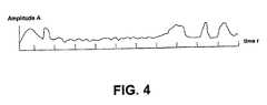
- FIG. 4illustrates a portion of sampled radio-frequency noise data
- FIG. 5is a schematic diagram of one method for analyzing RF noise in accordance with one embodiment of the present invention.
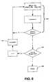
- FIG. 6is a schematic diagram of another process for analyzing RF noise in accordance with another embodiment of the present invention.
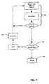
- FIG. 7is a schematic diagram of another method for analyzing RF noise in accordance with another embodiment of the present invention.
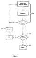
- FIG. 8is a schematic diagram of another method for analyzing RF noise in accordance with another embodiment of the present invention.
- FIG. 9is a schematic diagram of another embodiment for analyzing RF noise in accordance with another embodiment of the present invention.
- FIG. 10is a schematic diagram of another embodiment for analyzing RF noise in accordance with another embodiment of the present invention.
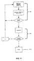
- FIG. 11is a schematic diagram of another method for analyzing RF noise in accordance with another embodiment of the present invention.
- FIG. 12is a schematic diagram of another method for analyzing RF noise in accordance with another embodiment of the present invention.
- FIG. 13is a schematic diagram of a representative hardware environment in accordance with an embodiment of the present invention.
- UWBUltra-wideband
- basebandbaseband
- impulseImpulse
- RFradio-frequency
- the basic conceptis to develop, transmit and receive an extremely short duration burst of radio-frequency (RF) energy—typically a few tens of picoseconds (trillionths of a second) to a few hundred nanoseconds (billionths of a second) in duration. These bursts represent from one to only a few cycles of an RF carrier wave.
- RFradio-frequency
- the resultant waveformsare extremely broadband, so much so that it is often difficult to determine an actual RF center frequency—thus, the term “carrier-free”.
- TDMAtime division multiple access
- CDMAcode division multiple access
- CDMACode Division Multiple Access
- UWB communication systemconstructed according to the present invention to increase the number of users that can be supported from one or more base stations.
- UWB channels sending and receiving data unaware of one anothermight include instances where two or more stand-alone UWB devices or a local home or office network are communicating in the same environment.
- noisemight be generated from a wide variety of devices from spark ignition engines to laptop computers. These, or other devices can forseeably be generating UWB pulse trains into channels already consumed by other UWB activity in the area. This potentially causes competition for bandwidth and/or pulse channels that may cause data errors. Inserting a UWB channel into this noise can reduce the quality of the channel, and reception of the UWB channel can be lost, as separating the noise from the timed pulses can become difficult.
- a UWB communication systemmay employ a plurality of distinct communication channels that may be managed and organized using the methods and devices described in U.S. patent application, Ser. No. 09/746,348, entitled “Pre-testing and Certification of Multiple Access Codes”, filed Dec. 21, 2000, and U.S. patent application, Ser. No. to be assigned, entitled “Encoding and Decoding Ultra-Wideband Information,” which are incorporated herein by reference in their entirety.
- One aspect of the above-identified inventionwill provide a method by which the system will pre-test, rank and assign UWB channels prior to any actual need for an unassigned channel. This will eliminate inefficiencies in channel allocation function and increase system efficiency. By constantly testing, analyzing, prioritizing and assigning a list of available channels, reliable and interference-free UWB communications will be realized.
- the present inventiondiscloses techniques used to digitally map and analyze the radio frequency (RF) noise floor specifically for UWB communications. Allocating channels effectively requires prior knowledge of the characteristics of the RF environment upon which the UWB channel will reside. By characterizing the noise that may be present in the time bins that are to be allocated to a channel, a determination can be made of possible interferences that will make that channel less than optimal for data transmission.
- RFradio frequency
- FIG. 1a schematic diagram of an exemplary UWB communication system 100 capable of utilizing a multiple access scheme in accordance with one embodiment of the present invention is illustrated.
- One or more wireless mobile units 102 capable of UWB communicationcommunicate with a UWB base station 104 .
- the base station 104may communicate directly with the dynamic database controller 106 , or it may communicate with the radio-frequency (RF) noise sensing antenna 101 .
- the dynamic database controller 106communicates with the base station 104 .
- the dynamic database controller 106includes a general computing device for executing its functions and communicates with a noise sampler 108 and a dynamic code database 110 .
- the dynamic database controller 106estimates a potential effect of the channel noise on a transmission quality of an unallocated channel based on the obtained information in operation 204 .
- a ratingis assigned by dynamic database controller 106 the to the unallocated channel based on the estimated potential effect. Based on the assigned rating, the channel is classified into a grade of service class or classification in operation 208 . Information relating to the now classified channel and its associated rating and grade of service class is then stored in the database 110 in operation 210 .
- FIG. 3 ais a schematic diagram of one embodiment of the noise sampler 108 illustrated in FIG. 1 .
- a time integrating correlator 306correlates the RF noise signal with a code sequence.
- an RF noise sensing antenna 101communicates with an RF amplifier 304 which communicates with a time integrating generator 306 .
- the time integrating generator 306also communicates with a multiple access code generator 308 .
- This embodimentmay be suitable for Code Division Multiple Access schemes. Time integrating correlators and code generators for these codes are known in the art.
- the RF noise samples for this approachmay be detected either with the antenna used for data reception or by the dedicated RF noise-sensing antenna 101 .
- FIG. 3 bis a schematic diagram of a preferred embodiment noise sampler 108 that utilizes real-time sampling of time windows or “time bins”.
- This noise sampler 108is based on a different access scheme than the access scheme utilized in FIG. 3 a .
- a RF receiving antenna 310is coupled to a RF amplifier 312 .
- the RF amplifier 312 and a Time Hopping code generator 314are both coupled to a multiplexer (MUX) 316 which, in turn is coupled to Hold logic 318 .
- MUXmultiplexer
- a pseudo-random Time Hopping sequenceis used together with a Time Division Multiple Access scheme (TH-TDMA).
- TH-TDMATime Division Multiple Access scheme
- the RF noise sensing antenna 101is used to sense the noise present in the time bins to be occupied by a particular unallocated Time Hopping sequence.
- the Time Hopping sequenceis used to control the MUX 316 that allows the input samples to be held and digitized at the appropriate times matching the times that would be allocated to the Time Hopping sequence being tested.
- FIG. 4represents a frame of multiple-access data depicting amplitude (A) vs. time (t) and a hypothetical noise signature.
- f jrepresents the frame number and t i represents a time bin within a frame.
- the index jruns from 0 to N and the index i runs from 0 to n.
- Time f 0 t 0is the start of frame zero at time zero and is considered an absolute time and subsequent times are referenced relative to it.
- Time f j+1 t i ⁇ f j t iis the time period for one data frame.
- Time f j t i+1 ⁇ f j t iis considered one time bin.
- the duration of a time binmay vary from approximately 40 picoseconds to approximately 100 nanoseconds.
- a UWB communication channel constructed according to the present inventioncomprises a plurality of time bins t i . All RF amplitude sampling of time bins t i for the following methods can be performed at time t i +t i+1 /2, or in other words, the center of the time bin. Other suitable sampling methods can also be performed to obtain a sample of RF noise. Obtaining and analyzing RF noise samples may be performed by a programmable general computing device programmed to perform the described operations. This analysis may be performed by the dynamic database controller 106 , the dynamic code database 110 , or another suitable device.
- the following data sample matrix Srepresents one sample set of collected RF noise data, each row is one frame of data and each column represents the same time bin t i in each frame. If N+1 frames are sampled with n time bins in each frame, then the stored matrix is as depicted in S.
- the RF noise data sampleswill probably contain data from other ultra-wideband devices or other types of noise.
- impulsive noisesuch as automobile ignition systems that produce random bursts of nanosecond pulses or other ultra-wideband time pulses may be present.
- the following embodiments of the present inventionanalyze RF noise with respect to time to determine the amount and nature of noise present in selected channels. Once the noise in each channel is determined, the channels are ranked based on the amount and type of noise present.
- Random noisealso known as additive white Gaussian noise
- a UWB communication channelcan be inserted over additive white Gaussian noise.
- RF noisethat is systematically increasing or decreasing cannot be removed and will decrease the reliability or otherwise interfere with a UWB channel placed over that noise.
- the nature of the noisecan be determined.
- the absolute value of the difference of selected RF noise data samplescan show whether or not the noise is increasing or decreasing.
- different embodiments of the invention described belowwill also determine the average of the noise, the change in the RF noise from one time bin t i to another time bin t i and the rate of change of two selected RF noise data samples.
- the resultant average for each time bin t irepresents the average RF noise amplitude for that specific time period.
- the RF noise amplitudes for adjacent time periodscan then be evaluated to detect if a periodic signal with a main periodicity of one frame f j is present. If periodic noise is present, an estimation of the effect of the noise on the transmission quality is performed by the dynamic database controller 106 , illustrated in FIG. 2 .
- FIG. 6another process according to the present invention is illustrated which evaluates the RF noise amplitude data.
- step 605the difference of the amplitudes of RF noise samples in adjacent time bins t i in the same frame f j is taken. This process is repeated in step 605 until all of the adjacent time bins t i in one frame f j have been evaluated.
- step 610when the end of the frame is reached, the next frame f j+1 is analyzed according to step 605 . In this manner, all of the adjacent time bins t i in a plurality of frames f j are evaluated.
- This first difference calculation M2 ijobtains the difference in RF noise amplitudes in adjacent time bins t i within a frame f j .
- this informationcan be used to determine if the RF noise is increasing or decreasing with time by the dynamic database controller 106 .
- equation (1)can be used to obtain the absolute value of a difference of adjacent time bin t i RF noise amplitude averages.
- equation (3)an absolute value of the difference between averaged RF noise samples in adjacent time bins t i is obtained.
- the data obtained after this analysiswill be used by the dynamic database controller 106 , or other suitable device to determine the change in RF noise amplitudes in adjacent time bins t l .
- FIG. 7a process to obtain a second difference of adjacent time bins t i is illustrated.
- This processuses the data obtained from equation (2).
- this informationcan be used to determine the rate of change of the RF noise by the dynamic database controller 106 , or other suitable devices.
- the rate of change of the RF noisecan help to determine the quality of a channel and can also be used to estimate a potential effect of the noise on a transmission.
- equation (3)can be used to obtain the absolute value of a second difference of adjacent time bin t i RF noise amplitude averages.
- equation (5)an absolute value of the second difference between averaged RF noise samples in adjacent time bins t i is obtained. This data is used by the dynamic database controller 106 , or other suitable device to determine the rate of change, or how fast the RF noise amplitudes in adjacent time bins t i is changing.
- FIG. 8an alternative process for evaluating the RF noise amplitude in a data sample for use in an UWB communication system constructed according to the present invention is illustrated.
- This processuses sampled RF amplitude data from two consecutive frames f i contained in the matrix S, defined above. This is illustrated in step 805 of FIG. 8 where the absolute value of the difference between the same time bin t i in adjacent frames f j is calculated. In step 810 , the difference of adjacent time bins t i is repeated until all of the frames f j have been evaluated. When the last frame f j has been evaluated, the program continues by moving to the next time bin t i in step 815 . In this manner, all time bins t i in a sample of RF noise amplitude data is evaluated.
- This processobtains a change in the RF noise amplitude in corresponding time bins t i across successive frames f j .
- the processis complete, and the dynamic database controller 106 conducts an analysis of whether or not a detected RF noise may be repetitive. If a repetitive RF noise is found through this analysis, it can be avoided thereby improving the quality and reliability of UWB communications performed according to the present invention.
- the rate of change of the RF noise amplitude in corresponding time bins t i across successive frames f jis determined.
- step 905the absolute value of the difference of the change in the same time bins t i across multiple frames f j is obtained.
- step 910when the end of a column of frames f j is reached, the program increments to the next time bin t i in step 915 . This process is repeated until all of the differences of the same time bins t i are obtained for all frames f j .
- the processis complete, and the dynamic database controller 106 uses this information to determine the rate of change of the RF noise amplitude data in corresponding time bins t i .
- the rate of change informationcan help to determine the characteristic of the RF noise amplitudes in specific time bins t i .
- FIGS. 10-12a preferred embodiment of the present invention is illustrated. Shown in FIGS. 10-12 are processes used to examine RF noise amplitude in pseudo-randomly spaced time bins. As discussed in prior sections, pseudo-random distribution of time bins is accomplished through “time-hopping”. In a preferred embodiment of the invention, a plurality of pseudo-randomly spaced time bins are selected and allocated to a specific channel. In this manner, a plurality of channels each comprising a plurality of time bins that do not overlap can be transmitted simultaneously. The number of time bins in each channel is determined according to the bandwidth requirement for the type of information communicated in that channel.
- the plurality of pseudo-randomly spaced time binsare located within a frame f.
- f jis equal to frame j
- t kis the k th time bin allocated to the same channel and frame f j
- kis a frame-periodic pseudo-noise sequence of length b
- Nis the number of frames over which the sequence is averaged. Illustrated in FIG. 10 is a flowchart illustrating the steps a program will perform to analyze sampled RF noise data.
- step 1010the RF noise amplitude found in the same pseudo-randomly placed time bin t b in each frame f j is summed. In step 1010 , that sum of RF noise amplitudes is averaged. In step 1015 , the program moves to the next column representing a second pseudo-randomly placed time bin t b . The sum for the second column is then averaged in step 1010 , and this process of summing each column representing a pseudo-randomly placed time bin t b is repeated until all of the pseudo-randomly placed time bins t b in all of the frames f j have been summed and averaged, finishing at step 1020 .
- the resultant average for each pseudo-randomly placed time bin t brepresents the average RF noise amplitude for that specific channel to which the pseudo-randomly placed time bins t b have been allocated.
- the RF noise amplitudes for the specific channelcan then be evaluated to detect if a periodic signal or other types of RF noise is present. If RF noise is present, an estimation of the effect of the noise on the transmission quality is performed by the dynamic database controller 106 , illustrated in FIG. 2 . Additionally, the data obtained from the process illustrated in FIG. 10 can be used to rank channel quality based on the RF noise present in that UWB communication channel.
- FIG. 11another process according to the present invention is illustrated which evaluates the RF noise amplitude data.
- t lis not the temporally next time bin but instead is the time bin that next follows t k in a sequence of pseudo-randomly placed time bins.
- step 1105the difference of the amplitudes of RF noise samples in pseudo-randomly placed time bins t b in the same frame f j is taken. This process is repeated until all of the pseudo-randomly placed time bins t i allocated to a specific channel in one frame f j have been evaluated.
- step 1110when the end of the frame f j is reached, the next frame f j is analyzed according to step 1105 .
- This first difference calculation M 7 jobtains the difference in RF noise amplitudes in sequential pseudo-randomly placed time bins within a frame.
- this informationmay be used to determine if the RF noise is increasing or decreasing in the specific UWB communication channel that has been allocated to those sampled pseudo-randomly placed time bins t b .
- the data obtained by equation (8)can be used to obtain the absolute value of a difference of the RF noise amplitude averages in channel adjacent pseudo-randomly placed time bins t b .
- Equation (10)an absolute value of the difference between averaged RF noise samples in channel adjacent pseudo-randomly placed time bins t b is obtained.
- M 6 lis the time bin that follows M 6 k in a sequence of pseudo-randomly placed time bins allocated to a specific UWB communication channel. These time bins are referred to as “channel adjacent” time bins.
- the data obtained after this analysiswill be used by the dynamic database controller 106 , or other suitable device to determine the change in RF noise amplitudes in a UWB communication channel that has been allocated specific pseudo-randomly placed time bins.
- FIG. 12a process to obtain a second difference of pseudo-random time bins t b is illustrated.
- This processuses the data obtained from equation (10).
- M 7 lis the time bin that follows M 7 k in a sequence of pseudo-randomly placed time bins allocated to a specific UWB communication channel.
- step 1205the absolute value of the difference of the change in channel adjacent pseudo-randomly placed time bins t b in the same frame f j is obtained. This process is repeated in step 1205 until all of the data from equation (10) has been evaluated.
- step 1210when the end of the frame f j is reached, the next frame f j is analyzed according to step 1205 . In this manner, all of the data from equation (10) is evaluated.
- This second difference calculation M8 jobtains the second difference of RF noise amplitudes of channel adjacent time bins t b within a frame f j .
- this informationmay be used to determine the quality of a channel which will later be used in the process for ranking channels to be described below.
- the above-described methods and processesare used to obtain and manipulate data used for evaluating RF noise amplitudes that may be present during transmission of a UWB communication channel constructed according to the present invention.
- the above-described methodsquantify the type of RF noise that may be present. For example, narrow duration noise, wide duration noise, additive white Gaussian noise, repetitive noise, and other types of RF noise can all be evaluated using the above-described methods.
- This informationis used to grade or rank each UWB channel that is to be transmitted.
- time binswill be created to correspond with each UWB channel's statistical probability for optimum suitability in descending order from channels of highest quality to channels of lowest quality.
- a channel assigned for the transmission of data which requires high transmission rateswould receive a high quality channel containing low or non-existent amounts of RF noise.
- a UWB channel assigned to carry video datamay receive a slightly lower quality channel that has slightly higher amounts of RF noise present.
- a UWB channel for transmitting audio signalsmay receive a low quality channel containing high amounts of RF noise, and some UWB channels may not be allocated any data because analysis has indicated that the RF noise present is too great to carry any data reliably.
- Time binswill ideally be created to correspond to each channel's statistical probability for optimum suitability in descending order from Data (channels of highest quality), Video (next highest quality), Audio (lowest quality) and “Not Suitable” (channel quality is not suitable for pulse train insertion).
- PBERprojected bit error rate
- nis the number of bits transmitted in an ultra-wideband communication channel
- CLis the confidence level (that is, the statistical confidence that the bit error rate (BER) will be less than or equal to the PBER).
- Nis the total number of bit errors that occur during the transmission
- krefers to the k th bit error.
- This equationcan be solved by iterative methods by inserting CL, and yields a PBER that is constantly updated as a transmission proceeds. For example, a CL of 0.95 can be inserted into the equation and a PBER can be determined. As the PBER changes, the amount of data transmitted may be decreased to maintain channel quality or the data transmission on that specific channel may be terminated and switched to another ultra-wideband channel with a lower PBER.
- FIG. 13illustrates a representative hardware environment or workstation by which embodiments of the present invention may be carried out.
- the various sub-components of each of the components embodying the inventionmay also be considered components of the UWB communication system.
- particular software modules executed on any component of the systemmay also be considered components of the system.
- the hardware configuration illustrated in FIG. 13includes a central processing unit 20 , such as a microprocessor, and a number of other units interconnected via a system bus 25 .
- the workstation shown in FIG. 13includes a Random Access Memory (RAM) 30 , Read Only Memory (ROM) 35 , an I/O adapter 40 for connecting peripheral devices such as disk storage units 42 to the bus 25 , a user interface adapter 45 for connecting a keyboard 50 , a mouse 55 , a speaker 60 , a microphone 65 , and/or other user interface devices such as a touch screen (not shown) to the bus 25 , communication adapter 70 for connecting the workstation to a communication network 75 (e.g., a data processing network) and a display adapter 80 for connecting the bus 25 to a display device 85 .
- a communication network 75e.g., a data processing network
- display adapter 80for connecting the bus 25 to a display device 85 .
- An embodiment of the present inventionmay be written using JAVA, C, C++, or other suitable computer languages and may utilize object oriented programming methodology.
Landscapes
- Engineering & Computer Science (AREA)
- Computer Networks & Wireless Communication (AREA)
- Signal Processing (AREA)
- Quality & Reliability (AREA)
- Radar, Positioning & Navigation (AREA)
- Remote Sensing (AREA)
- Physics & Mathematics (AREA)
- General Physics & Mathematics (AREA)
- Electromagnetism (AREA)
- Mobile Radio Communication Systems (AREA)
Abstract
Description
M2ij=|A(fjti+1)−A(fjtl)|. (2)
{overscore (M2i)}=|{overscore (M1i+1)}−{overscore (M1i)}|. (3)
M3ij=|M2i+1−M2i| (4)
{overscore (M3i)}=|{overscore (M2i+1)}−{overscore (M2i)}| (5)
M4ji=|A(fj+1ti)−A(fjti)|. (6)
M5ji=|M4i+1−M4i| (7)
M7j=|A(fjtl)−A(fjtk)|, (9)
where tlis the pseudo-randomly placed time bin that follows tkin the pseudo-randomly placed sequence allocated to a specific UWB communication channel. That is, tlis not the temporally next time bin but instead is the time bin that next follows tkin a sequence of pseudo-randomly placed time bins. In
{overscore (M7j)}=|{overscore (M6l)}−{overscore (M6k)}| (10)
M8j=|M7l−M7k| (11)
{overscore (M8j)}=|{overscore (M7l)}−{overscore (M7k)}| (12)
Claims (46)
{overscore (M2i)}=|{overscore (M1i+1)}−{overscore (M1i)}|,
{overscore (M3i)}=|{overscore (M2i+1)}−{overscore (M2i)}|,
M4ji=|A(tj+1ti)−A(fjti)|,
M5ji=|M4i+1−M4i|,
{overscore (M7j)}=|{overscore (M6i)}−{overscore (M6k)}|,
{overscore (M8j)}=|{overscore (M7t)}−{overscore (M7k)}|,
Priority Applications (6)
| Application Number | Priority Date | Filing Date | Title |
|---|---|---|---|
| US09/802,603US6937674B2 (en) | 2000-12-14 | 2001-03-09 | Mapping radio-frequency noise in an ultra-wideband communication system |
| AU2002230984AAU2002230984A1 (en) | 2000-12-14 | 2001-12-13 | Mapping radio-frequency noise in an ultra-wideband communication system |
| PCT/US2001/048910WO2002049245A1 (en) | 2000-12-14 | 2001-12-13 | Mapping radio-frequency noise in an ultra-wideband communication system |
| US10/932,969US7397867B2 (en) | 2000-12-14 | 2004-09-02 | Mapping radio-frequency spectrum in a communication system |
| US11/116,890US7349485B2 (en) | 2000-12-14 | 2005-04-27 | Mapping radio-frequency noise in an ultra-wideband communication system |
| US11/977,806US20080107162A1 (en) | 2000-12-14 | 2007-10-26 | Mapping radio-frequency spectrum in a communication system |
Applications Claiming Priority (2)
| Application Number | Priority Date | Filing Date | Title |
|---|---|---|---|
| US25546900P | 2000-12-14 | 2000-12-14 | |
| US09/802,603US6937674B2 (en) | 2000-12-14 | 2001-03-09 | Mapping radio-frequency noise in an ultra-wideband communication system |
Related Child Applications (2)
| Application Number | Title | Priority Date | Filing Date |
|---|---|---|---|
| US10/932,969Continuation-In-PartUS7397867B2 (en) | 2000-12-14 | 2004-09-02 | Mapping radio-frequency spectrum in a communication system |
| US11/116,890ContinuationUS7349485B2 (en) | 2000-12-14 | 2005-04-27 | Mapping radio-frequency noise in an ultra-wideband communication system |
Publications (2)
| Publication Number | Publication Date |
|---|---|
| US20040264609A1 US20040264609A1 (en) | 2004-12-30 |
| US6937674B2true US6937674B2 (en) | 2005-08-30 |
Family
ID=26944718
Family Applications (2)
| Application Number | Title | Priority Date | Filing Date |
|---|---|---|---|
| US09/802,603Expired - LifetimeUS6937674B2 (en) | 2000-12-14 | 2001-03-09 | Mapping radio-frequency noise in an ultra-wideband communication system |
| US11/116,890Expired - Fee RelatedUS7349485B2 (en) | 2000-12-14 | 2005-04-27 | Mapping radio-frequency noise in an ultra-wideband communication system |
Family Applications After (1)
| Application Number | Title | Priority Date | Filing Date |
|---|---|---|---|
| US11/116,890Expired - Fee RelatedUS7349485B2 (en) | 2000-12-14 | 2005-04-27 | Mapping radio-frequency noise in an ultra-wideband communication system |
Country Status (3)
| Country | Link |
|---|---|
| US (2) | US6937674B2 (en) |
| AU (1) | AU2002230984A1 (en) |
| WO (1) | WO2002049245A1 (en) |
Cited By (64)
| Publication number | Priority date | Publication date | Assignee | Title |
|---|---|---|---|---|
| US20030202537A1 (en)* | 2001-09-26 | 2003-10-30 | General Atomics | Method and apparatus for data transfer using a time division multiple frequency scheme supplemented with polarity modulation |
| US20040008729A1 (en)* | 2001-09-26 | 2004-01-15 | General Atomics | Method and apparatus for data transfer using a time division multiple frequency scheme with additional modulation |
| US20040048574A1 (en)* | 2001-09-26 | 2004-03-11 | General Atomics | Method and apparatus for adapting multi-band ultra-wideband signaling to interference sources |
| US20050124293A1 (en)* | 2003-12-04 | 2005-06-09 | Alicherry Mansoor A.K. | Method and apparatus for mobile telephone locatability |
| US20070143078A1 (en)* | 2001-03-26 | 2007-06-21 | Martin Vetterli | Sampling method, reconstruction method, and device for sampling and/or reconstructing signals |
| US20070162964A1 (en)* | 2006-01-12 | 2007-07-12 | Wang Liang-Yun | Embedded system insuring security and integrity, and method of increasing security thereof |
| US20070242026A1 (en)* | 2006-04-14 | 2007-10-18 | Qualcomm Incorporated | Apparatus and method of pulse generation for ultra-wideband transmission |
| US20070257827A1 (en)* | 2006-04-20 | 2007-11-08 | Qualcomm Incorporated | Low power output stage |
| US20070286274A1 (en)* | 2006-04-19 | 2007-12-13 | Qualcomm Incorporated | Apparatus and method of low latency multi-hop communication |
| US20080088416A1 (en)* | 2006-10-03 | 2008-04-17 | John Frederick Crooks | Methods and Apparatus for Analyzing Signal Conditions Affecting Operation of an RFID Communication Device |
| US20080112512A1 (en)* | 2006-11-15 | 2008-05-15 | Qualcomm Incorporated | Transmitted reference signaling scheme |
| US20080116941A1 (en)* | 2006-11-16 | 2008-05-22 | Qualcomm Incorporated | Peak signal detector |
| US20080117804A1 (en)* | 2006-11-16 | 2008-05-22 | Qualcomm Incorporated | Multiple access techniques for a wireless communication medium |
| US20080117939A1 (en)* | 2006-11-16 | 2008-05-22 | Qualcomm Incorporated | Multiple access techniques for a wireless communiation medium |
| US20080144560A1 (en)* | 2006-12-15 | 2008-06-19 | Qualcomm Incorporated | Channel access scheme for ultra-wide band communication |
| US7403575B2 (en) | 2001-09-26 | 2008-07-22 | General Atomics | Method and apparatus for adapting signaling to maximize the efficiency of spectrum usage for multi-band systems in the presence of interference |
| US20080246548A1 (en)* | 2007-04-05 | 2008-10-09 | Qualcomm Incorporated | Method and apparatus for generating oscillating signals |
| US7436899B2 (en) | 2001-09-26 | 2008-10-14 | General Atomics | Method and apparatus for data transfer using wideband bursts |
| US20080258562A1 (en)* | 2007-04-23 | 2008-10-23 | Qualcomm Incorporated | Apparatus and method for generating fine timing from coarse timing source |
| US20090017782A1 (en)* | 2007-07-12 | 2009-01-15 | Pavel Monat | Method for determining line-of-sight (los) distance between remote communications devices |
| US20090021408A1 (en)* | 2007-07-18 | 2009-01-22 | Lee Chong U | Adaptive dynamic range control |
| US20090034591A1 (en)* | 2007-07-30 | 2009-02-05 | David Jonathan Julian | Method of pairing devices |
| US20090067407A1 (en)* | 2007-09-11 | 2009-03-12 | Qualcomm Incorporated | Keep-alive for wireless networks |
| US20090080542A1 (en)* | 2007-09-25 | 2009-03-26 | Qualcomm Incorporated | Interference Mitigation For Impulse-Based Communication |
| US20090224832A1 (en)* | 2008-03-10 | 2009-09-10 | Qualcomm Incorporated | System and method of enabling a signal processing device in a relatively fast manner to process a low duty cycle signal |
| US20090224860A1 (en)* | 2008-03-10 | 2009-09-10 | Qualcomm Incorporated | System and method of using residual voltage from a prior operation to establish a bias voltage for a subsequent operation |
| US20090243699A1 (en)* | 2008-03-25 | 2009-10-01 | Qualcomm Incorporated | System and method of companding an input signal of an energy detecting receiver |
| US20090251208A1 (en)* | 2008-04-08 | 2009-10-08 | Qualcomm Incorporated | Low power slicer-based demodulator for ppm |
| US20100005371A1 (en)* | 2008-07-07 | 2010-01-07 | Qualcomm Incorporated | System and method of puncturing pulses in a receiver or transmitter |
| US20100020863A1 (en)* | 2008-07-25 | 2010-01-28 | Qualcomm Incorporated | Determination of receive data values |
| US20100046443A1 (en)* | 2008-08-22 | 2010-02-25 | Qualcomm Incorporated | Addressing schemes for wireless communication |
| US7716001B2 (en) | 2006-11-15 | 2010-05-11 | Qualcomm Incorporated | Delay line calibration |
| US20100172393A1 (en)* | 2009-01-06 | 2010-07-08 | Qualcomm Incorporated | Pulse arbitration for network communications |
| US7855611B2 (en) | 2006-11-15 | 2010-12-21 | Qualcomm Incorporated | Delay line calibration |
| US20110129099A1 (en)* | 2007-08-28 | 2011-06-02 | Qualcomm Incorporated | Apparatus and method for modulating an amplitude, phase or both of a periodic signal on a per cycle basis |
| US7965805B2 (en) | 2007-09-21 | 2011-06-21 | Qualcomm Incorporated | Signal generator with signal tracking |
| US8275373B2 (en) | 2007-09-28 | 2012-09-25 | Qualcomm Incorporated | Randomization of periodic channel scans |
| US8289159B2 (en) | 2006-04-26 | 2012-10-16 | Qualcomm Incorporated | Wireless localization apparatus and method |
| US8326246B2 (en) | 2007-07-10 | 2012-12-04 | Qualcomm Incorporated | Super regenerative (SR) apparatus having plurality of parallel SR amplifiers tuned to distinct frequencies |
| US8385474B2 (en) | 2007-09-21 | 2013-02-26 | Qualcomm Incorporated | Signal generator with adjustable frequency |
| US8406794B2 (en) | 2006-04-26 | 2013-03-26 | Qualcomm Incorporated | Methods and apparatuses of initiating communication in wireless networks |
| US8446976B2 (en) | 2007-09-21 | 2013-05-21 | Qualcomm Incorporated | Signal generator with adjustable phase |
| US8451710B2 (en) | 2006-04-26 | 2013-05-28 | Qualcomm Incorporated | Sub-packet pulse-based communications |
| US8473013B2 (en) | 2008-04-23 | 2013-06-25 | Qualcomm Incorporated | Multi-level duty cycling |
| US8483639B2 (en) | 2008-05-06 | 2013-07-09 | Qualcomm Incorporated | AGC for slicer-based low power demodulator |
| US8514911B2 (en) | 2009-05-13 | 2013-08-20 | Qualcomm Incorporated | Method and apparatus for clock drift compensation during acquisition in a wireless communication system |
| US8538345B2 (en) | 2007-10-09 | 2013-09-17 | Qualcomm Incorporated | Apparatus including housing incorporating a radiating element of an antenna |
| US8552903B2 (en) | 2006-04-18 | 2013-10-08 | Qualcomm Incorporated | Verified distance ranging |
| US8589720B2 (en) | 2008-04-15 | 2013-11-19 | Qualcomm Incorporated | Synchronizing timing mismatch by data insertion |
| US8600373B2 (en) | 2006-04-26 | 2013-12-03 | Qualcomm Incorporated | Dynamic distribution of device functionality and resource management |
| US8612693B2 (en) | 2009-03-19 | 2013-12-17 | Qualcomm Incorporated | Optimized transfer of packets in a resource constrained operating environment |
| US8644396B2 (en) | 2006-04-18 | 2014-02-04 | Qualcomm Incorporated | Waveform encoding for wireless applications |
| US8837724B2 (en) | 2007-03-27 | 2014-09-16 | Qualcomm Incorporated | Synchronization test for device authentication |
| US8886125B2 (en) | 2006-04-14 | 2014-11-11 | Qualcomm Incorporated | Distance-based association |
| US9083448B2 (en) | 2007-10-26 | 2015-07-14 | Qualcomm Incorporated | Preamble capture and medium access control |
| US9124357B2 (en) | 2006-04-20 | 2015-09-01 | Qualcomm Incorporated | Media access control for ultra-wide band communication |
| US9141961B2 (en) | 2007-06-20 | 2015-09-22 | Qualcomm Incorporated | Management of dynamic mobile coupons |
| US9215581B2 (en) | 2006-04-14 | 2015-12-15 | Qualcomm Incorported | Distance-based presence management |
| US9483769B2 (en) | 2007-06-20 | 2016-11-01 | Qualcomm Incorporated | Dynamic electronic coupon for a mobile environment |
| US9524502B2 (en) | 2007-06-20 | 2016-12-20 | Qualcomm Incorporated | Management of dynamic electronic coupons |
| US20180192422A1 (en)* | 2017-01-03 | 2018-07-05 | Network Performance Research Group Llc | Over the air signaling of dynamic frequency selection (dfs) operating parameters to client devices |
| US10542372B2 (en) | 2011-03-15 | 2020-01-21 | Qualcomm Incorporated | User identification within a physical merchant location through the use of a wireless network |
| US10951247B1 (en) | 2019-10-10 | 2021-03-16 | Viasat, Inc. | Channelizing a wideband waveform for transmission on a spectral band comprising unavailable channel segments |
| US11082101B2 (en) | 2019-10-10 | 2021-08-03 | Viasat, Inc. | Channelizing and beamforming a wideband waveform |
Families Citing this family (9)
| Publication number | Priority date | Publication date | Assignee | Title |
|---|---|---|---|---|
| US7397867B2 (en)* | 2000-12-14 | 2008-07-08 | Pulse-Link, Inc. | Mapping radio-frequency spectrum in a communication system |
| US20030235236A1 (en)* | 2002-06-21 | 2003-12-25 | Pulse-Link, Inc. | Ultra-wideband communication through a wired medium |
| US20040156446A1 (en) | 2002-06-21 | 2004-08-12 | John Santhoff | Optimization of ultra-wideband communication through a wire medium |
| KR100562899B1 (en) | 2003-05-03 | 2006-03-21 | 삼성전자주식회사 | Wireless-compatible Mac frame transmission and reception method and apparatus |
| US7676194B2 (en) | 2003-08-22 | 2010-03-09 | Rappaport Theodore S | Broadband repeater with security for ultrawideband technologies |
| US8902875B2 (en)* | 2005-08-25 | 2014-12-02 | Broadcom Corporation | Subcarrier allocation in OFDMA with imperfect channel state information at the transmitter |
| GB2432086B (en)* | 2005-11-01 | 2007-12-12 | Motorola Inc | Retransmission in a cellular communication system |
| KR101211225B1 (en)* | 2007-01-12 | 2012-12-11 | 인터디지탈 테크날러지 코포레이션 | Method and apparatus for measuring interference in wireless stations |
| US12096343B2 (en)* | 2021-07-30 | 2024-09-17 | Hewlett Packard Enterprise Development Lp | Evaluating cellular channels |
Citations (33)
| Publication number | Priority date | Publication date | Assignee | Title |
|---|---|---|---|---|
| US3668639A (en) | 1971-05-07 | 1972-06-06 | Itt | Sequency filters based on walsh functions for signals with three space variables |
| US3678204A (en) | 1970-10-26 | 1972-07-18 | Itt | Signal processing and transmission by means of walsh functions |
| US4506267A (en) | 1983-01-26 | 1985-03-19 | Geophysical Survey Systems, Inc. | Frequency independent shielded loop antenna |
| US4641317A (en) | 1984-12-03 | 1987-02-03 | Charles A. Phillips | Spread spectrum radio transmission system |
| US4651152A (en) | 1983-09-26 | 1987-03-17 | Geophysical Survey Systems, Inc. | Large relative bandwidth radar |
| US4743906A (en) | 1984-12-03 | 1988-05-10 | Charles A. Phillips | Time domain radio transmission system |
| US4813057A (en) | 1984-12-03 | 1989-03-14 | Charles A. Phillips | Time domain radio transmission system |
| US5056051A (en)* | 1989-06-06 | 1991-10-08 | Technology For Communications International | Signal direction finding processor using fast Fourier transforms for receiver matching |
| US5134408A (en) | 1991-01-30 | 1992-07-28 | Geophysical Survey Systems, Inc. | Detection of radar signals with large radar signatures |
| US5148174A (en) | 1991-02-13 | 1992-09-15 | Geophysical Survey Systems, Inc. | Selective reception of carrier-free radar signals with large relative bandwidth |
| US5153595A (en) | 1990-03-26 | 1992-10-06 | Geophysical Survey Systems, Inc. | Range information from signal distortions |
| US5159343A (en) | 1990-03-26 | 1992-10-27 | Geophysical Survey Systems, Inc. | Range information from signal distortions |
| US5189701A (en)* | 1991-10-25 | 1993-02-23 | Micom Communications Corp. | Voice coder/decoder and methods of coding/decoding |
| US5237587A (en)* | 1992-11-20 | 1993-08-17 | Magnavox Electronic Systems Company | Pseudo-noise modem and related digital correlation method |
| US5307081A (en) | 1990-11-27 | 1994-04-26 | Geophysical Survey Systems, Inc. | Radiator for slowly varying electromagnetic waves |
| US5325203A (en)* | 1992-04-16 | 1994-06-28 | Sony Corporation | Adaptively controlled noise reduction device for producing a continuous output |
| US5363108A (en) | 1984-12-03 | 1994-11-08 | Charles A. Phillips | Time domain radio transmission system |
| US5365240A (en) | 1992-11-04 | 1994-11-15 | Geophysical Survey Systems, Inc. | Efficient driving circuit for large-current radiator |
| US5493691A (en) | 1993-12-23 | 1996-02-20 | Barrett; Terence W. | Oscillator-shuttle-circuit (OSC) networks for conditioning energy in higher-order symmetry algebraic topological forms and RF phase conjugation |
| US5523758A (en) | 1990-01-25 | 1996-06-04 | Geophysical Survey Systems, Inc. | Sliding correlator for nanosecond pulses |
| US5586145A (en) | 1993-01-11 | 1996-12-17 | Morgan; Harry C. | Transmission of electronic information by pulse position modulation utilizing low average power |
| US5589884A (en)* | 1993-10-01 | 1996-12-31 | Toko Kabushiki Kaisha | Adaptive quantization controlled by scene change detection |
| US5592177A (en) | 1993-06-11 | 1997-01-07 | Autometric, Incorporated | Polarization-rotation modulated, spread polarization-rotation, wide-bandwidth radio-wave communications system |
| US5610907A (en) | 1994-07-29 | 1997-03-11 | Barrett; Terence W. | Ultrafast time hopping CDMA-RF communications: code-as-carrier, multichannel operation, high data rate operation and data rate on demand |
| US5677927A (en) | 1994-09-20 | 1997-10-14 | Pulson Communications Corporation | Ultrawide-band communication system and method |
| US5687169A (en) | 1995-04-27 | 1997-11-11 | Time Domain Systems, Inc. | Full duplex ultrawide-band communication system and method |
| US5901172A (en) | 1997-06-11 | 1999-05-04 | Multispectral Solutions, Inc. | Ultra wideband receiver with high speed noise and interference tracking threshold |
| US6118817A (en)* | 1997-03-14 | 2000-09-12 | Microsoft Corporation | Digital video signal encoder and encoding method having adjustable quantization |
| US6249299B1 (en)* | 1998-03-06 | 2001-06-19 | Codonics, Inc. | System for printhead pixel heat compensation |
| US6275522B1 (en)* | 1998-01-14 | 2001-08-14 | Motorola, Inc. | Method for allocating data and power in a discrete, multi-tone communication system |
| US6363345B1 (en)* | 1999-02-18 | 2002-03-26 | Andrea Electronics Corporation | System, method and apparatus for cancelling noise |
| US6519559B1 (en)* | 1999-07-29 | 2003-02-11 | Intel Corporation | Apparatus and method for the enhancement of signals |
| US6721561B1 (en)* | 1999-10-19 | 2004-04-13 | Samsung Electronics Co., Ltd. | Method for building a home-zone database using measured power strength |
Family Cites Families (9)
| Publication number | Priority date | Publication date | Assignee | Title |
|---|---|---|---|---|
| WO1987004294A1 (en)* | 1986-01-06 | 1987-07-16 | Motorola, Inc. | Frame comparison method for word recognition in high noise environments |
| US6044083A (en)* | 1995-10-20 | 2000-03-28 | Zenith Electronics Corporation | Synchronous code division multiple access communication system |
| JPH09321736A (en)* | 1996-05-27 | 1997-12-12 | Sony Corp | Receiving method and receiver |
| US6047175A (en)* | 1996-06-28 | 2000-04-04 | Aironet Wireless Communications, Inc. | Wireless communication method and device with auxiliary receiver for selecting different channels |
| US5809059A (en)* | 1996-11-21 | 1998-09-15 | Motorola, Inc. | Method and apparatus for spread spectrum channel assignment |
| US6002673A (en)* | 1997-03-21 | 1999-12-14 | Lucent Technologies Inc. | Method for channel management in a TDMA communication system |
| US6108374A (en)* | 1997-08-25 | 2000-08-22 | Lucent Technologies, Inc. | System and method for measuring channel quality information |
| US6052407A (en)* | 1997-10-01 | 2000-04-18 | Lucent Technologies Inc. | Apparatus and method for detection frequency hopping patterns embedded in radio frequency noise |
| US6249229B1 (en)* | 1999-08-16 | 2001-06-19 | Checkpoint Systems, Inc., A Corp. Of Pennsylvania | Electronic article security system employing variable time shifts |
- 2001
- 2001-03-09USUS09/802,603patent/US6937674B2/ennot_activeExpired - Lifetime
- 2001-12-13WOPCT/US2001/048910patent/WO2002049245A1/ennot_activeApplication Discontinuation
- 2001-12-13AUAU2002230984Apatent/AU2002230984A1/ennot_activeAbandoned
- 2005
- 2005-04-27USUS11/116,890patent/US7349485B2/ennot_activeExpired - Fee Related
Patent Citations (35)
| Publication number | Priority date | Publication date | Assignee | Title |
|---|---|---|---|---|
| US3678204A (en) | 1970-10-26 | 1972-07-18 | Itt | Signal processing and transmission by means of walsh functions |
| US3668639A (en) | 1971-05-07 | 1972-06-06 | Itt | Sequency filters based on walsh functions for signals with three space variables |
| US4506267A (en) | 1983-01-26 | 1985-03-19 | Geophysical Survey Systems, Inc. | Frequency independent shielded loop antenna |
| US4651152A (en) | 1983-09-26 | 1987-03-17 | Geophysical Survey Systems, Inc. | Large relative bandwidth radar |
| US4641317A (en) | 1984-12-03 | 1987-02-03 | Charles A. Phillips | Spread spectrum radio transmission system |
| US4743906A (en) | 1984-12-03 | 1988-05-10 | Charles A. Phillips | Time domain radio transmission system |
| US4813057A (en) | 1984-12-03 | 1989-03-14 | Charles A. Phillips | Time domain radio transmission system |
| US4979186A (en) | 1984-12-03 | 1990-12-18 | Charles A. Phillips | Time domain radio transmission system |
| US5363108A (en) | 1984-12-03 | 1994-11-08 | Charles A. Phillips | Time domain radio transmission system |
| US5056051A (en)* | 1989-06-06 | 1991-10-08 | Technology For Communications International | Signal direction finding processor using fast Fourier transforms for receiver matching |
| US5523758A (en) | 1990-01-25 | 1996-06-04 | Geophysical Survey Systems, Inc. | Sliding correlator for nanosecond pulses |
| US5153595A (en) | 1990-03-26 | 1992-10-06 | Geophysical Survey Systems, Inc. | Range information from signal distortions |
| US5159343A (en) | 1990-03-26 | 1992-10-27 | Geophysical Survey Systems, Inc. | Range information from signal distortions |
| US5307081A (en) | 1990-11-27 | 1994-04-26 | Geophysical Survey Systems, Inc. | Radiator for slowly varying electromagnetic waves |
| US5134408A (en) | 1991-01-30 | 1992-07-28 | Geophysical Survey Systems, Inc. | Detection of radar signals with large radar signatures |
| US5148174A (en) | 1991-02-13 | 1992-09-15 | Geophysical Survey Systems, Inc. | Selective reception of carrier-free radar signals with large relative bandwidth |
| US5189701A (en)* | 1991-10-25 | 1993-02-23 | Micom Communications Corp. | Voice coder/decoder and methods of coding/decoding |
| US5325203A (en)* | 1992-04-16 | 1994-06-28 | Sony Corporation | Adaptively controlled noise reduction device for producing a continuous output |
| US5365240A (en) | 1992-11-04 | 1994-11-15 | Geophysical Survey Systems, Inc. | Efficient driving circuit for large-current radiator |
| US5237587A (en)* | 1992-11-20 | 1993-08-17 | Magnavox Electronic Systems Company | Pseudo-noise modem and related digital correlation method |
| US5586145A (en) | 1993-01-11 | 1996-12-17 | Morgan; Harry C. | Transmission of electronic information by pulse position modulation utilizing low average power |
| US5592177A (en) | 1993-06-11 | 1997-01-07 | Autometric, Incorporated | Polarization-rotation modulated, spread polarization-rotation, wide-bandwidth radio-wave communications system |
| US5589884A (en)* | 1993-10-01 | 1996-12-31 | Toko Kabushiki Kaisha | Adaptive quantization controlled by scene change detection |
| US5493691A (en) | 1993-12-23 | 1996-02-20 | Barrett; Terence W. | Oscillator-shuttle-circuit (OSC) networks for conditioning energy in higher-order symmetry algebraic topological forms and RF phase conjugation |
| US5610907A (en) | 1994-07-29 | 1997-03-11 | Barrett; Terence W. | Ultrafast time hopping CDMA-RF communications: code-as-carrier, multichannel operation, high data rate operation and data rate on demand |
| US6031862A (en) | 1994-09-20 | 2000-02-29 | Time Domain Corporation | Ultrawide-band communication system and method |
| US5677927A (en) | 1994-09-20 | 1997-10-14 | Pulson Communications Corporation | Ultrawide-band communication system and method |
| US5687169A (en) | 1995-04-27 | 1997-11-11 | Time Domain Systems, Inc. | Full duplex ultrawide-band communication system and method |
| US6118817A (en)* | 1997-03-14 | 2000-09-12 | Microsoft Corporation | Digital video signal encoder and encoding method having adjustable quantization |
| US5901172A (en) | 1997-06-11 | 1999-05-04 | Multispectral Solutions, Inc. | Ultra wideband receiver with high speed noise and interference tracking threshold |
| US6275522B1 (en)* | 1998-01-14 | 2001-08-14 | Motorola, Inc. | Method for allocating data and power in a discrete, multi-tone communication system |
| US6249299B1 (en)* | 1998-03-06 | 2001-06-19 | Codonics, Inc. | System for printhead pixel heat compensation |
| US6363345B1 (en)* | 1999-02-18 | 2002-03-26 | Andrea Electronics Corporation | System, method and apparatus for cancelling noise |
| US6519559B1 (en)* | 1999-07-29 | 2003-02-11 | Intel Corporation | Apparatus and method for the enhancement of signals |
| US6721561B1 (en)* | 1999-10-19 | 2004-04-13 | Samsung Electronics Co., Ltd. | Method for building a home-zone database using measured power strength |
Cited By (110)
| Publication number | Priority date | Publication date | Assignee | Title |
|---|---|---|---|---|
| US8160194B2 (en) | 2001-03-26 | 2012-04-17 | Qualcomm Incorporated | Sampling method, reconstruction method, and device for sampling and/or reconstructing signals |
| US20100246729A1 (en)* | 2001-03-26 | 2010-09-30 | Qualcomm Incorporated | Sampling method, reconstruction method, and device for sampling and/or reconstructing signals |
| US7991095B2 (en) | 2001-03-26 | 2011-08-02 | Qualcomm Incorporated | Sampling method, reconstruction method, and device for sampling and/or reconstructing signals |
| US8031820B2 (en) | 2001-03-26 | 2011-10-04 | Qualcomm Incorporated | Sampling method, reconstruction method, and device for sampling and/or reconstructing signals |
| US20070143078A1 (en)* | 2001-03-26 | 2007-06-21 | Martin Vetterli | Sampling method, reconstruction method, and device for sampling and/or reconstructing signals |
| US8077757B2 (en) | 2001-03-26 | 2011-12-13 | Qualcomm Incorporated | Sampling method for a spread spectrum communication system |
| US7436899B2 (en) | 2001-09-26 | 2008-10-14 | General Atomics | Method and apparatus for data transfer using wideband bursts |
| US20040048574A1 (en)* | 2001-09-26 | 2004-03-11 | General Atomics | Method and apparatus for adapting multi-band ultra-wideband signaling to interference sources |
| US20040008729A1 (en)* | 2001-09-26 | 2004-01-15 | General Atomics | Method and apparatus for data transfer using a time division multiple frequency scheme with additional modulation |
| US7321601B2 (en) | 2001-09-26 | 2008-01-22 | General Atomics | Method and apparatus for data transfer using a time division multiple frequency scheme supplemented with polarity modulation |
| US7342973B2 (en)* | 2001-09-26 | 2008-03-11 | General Atomics | Method and apparatus for adapting multi-band ultra-wideband signaling to interference sources |
| US7609608B2 (en) | 2001-09-26 | 2009-10-27 | General Atomics | Method and apparatus for data transfer using a time division multiple frequency scheme with additional modulation |
| US20030202537A1 (en)* | 2001-09-26 | 2003-10-30 | General Atomics | Method and apparatus for data transfer using a time division multiple frequency scheme supplemented with polarity modulation |
| US7403575B2 (en) | 2001-09-26 | 2008-07-22 | General Atomics | Method and apparatus for adapting signaling to maximize the efficiency of spectrum usage for multi-band systems in the presence of interference |
| US8149879B2 (en) | 2001-09-26 | 2012-04-03 | General Atomics | Method and apparatus for data transfer using a time division multiple frequency scheme supplemented with polarity modulation |
| US20080130685A1 (en)* | 2001-09-26 | 2008-06-05 | General Atomics | Method and Apparatus for Data Transfer Using a Time Division Multiple Frequency Scheme Supplemented with Polarity Modulation |
| US20050124293A1 (en)* | 2003-12-04 | 2005-06-09 | Alicherry Mansoor A.K. | Method and apparatus for mobile telephone locatability |
| US20070162964A1 (en)* | 2006-01-12 | 2007-07-12 | Wang Liang-Yun | Embedded system insuring security and integrity, and method of increasing security thereof |
| US9591470B2 (en) | 2006-04-14 | 2017-03-07 | Qualcomm Incorporated | System and method for enabling operations based on distance to and motion of remote device |
| US8886125B2 (en) | 2006-04-14 | 2014-11-11 | Qualcomm Incorporated | Distance-based association |
| US20070242026A1 (en)* | 2006-04-14 | 2007-10-18 | Qualcomm Incorporated | Apparatus and method of pulse generation for ultra-wideband transmission |
| US9215581B2 (en) | 2006-04-14 | 2015-12-15 | Qualcomm Incorported | Distance-based presence management |
| US9510383B2 (en) | 2006-04-14 | 2016-11-29 | Qualcomm Incorporated | System and method of associating devices based on actuation of input devices and signal strength |
| US8552903B2 (en) | 2006-04-18 | 2013-10-08 | Qualcomm Incorporated | Verified distance ranging |
| US8644396B2 (en) | 2006-04-18 | 2014-02-04 | Qualcomm Incorporated | Waveform encoding for wireless applications |
| US8654868B2 (en) | 2006-04-18 | 2014-02-18 | Qualcomm Incorporated | Offloaded processing for wireless applications |
| US20070286274A1 (en)* | 2006-04-19 | 2007-12-13 | Qualcomm Incorporated | Apparatus and method of low latency multi-hop communication |
| US8811456B2 (en) | 2006-04-19 | 2014-08-19 | Qualcomm Incorporated | Apparatus and method of low latency multi-hop communication |
| US7576605B2 (en) | 2006-04-20 | 2009-08-18 | Qualcomm Incorporated | Low power output stage |
| US9124357B2 (en) | 2006-04-20 | 2015-09-01 | Qualcomm Incorporated | Media access control for ultra-wide band communication |
| US20070257827A1 (en)* | 2006-04-20 | 2007-11-08 | Qualcomm Incorporated | Low power output stage |
| US8553745B2 (en) | 2006-04-26 | 2013-10-08 | Qualcomm Incorporated | Inter-pulse duty cycling |
| US8527016B2 (en) | 2006-04-26 | 2013-09-03 | Qualcomm Incorporated | Wireless device communication with multiple peripherals |
| US8451710B2 (en) | 2006-04-26 | 2013-05-28 | Qualcomm Incorporated | Sub-packet pulse-based communications |
| US8600373B2 (en) | 2006-04-26 | 2013-12-03 | Qualcomm Incorporated | Dynamic distribution of device functionality and resource management |
| US8406794B2 (en) | 2006-04-26 | 2013-03-26 | Qualcomm Incorporated | Methods and apparatuses of initiating communication in wireless networks |
| US8289159B2 (en) | 2006-04-26 | 2012-10-16 | Qualcomm Incorporated | Wireless localization apparatus and method |
| US20080088416A1 (en)* | 2006-10-03 | 2008-04-17 | John Frederick Crooks | Methods and Apparatus for Analyzing Signal Conditions Affecting Operation of an RFID Communication Device |
| US8207826B2 (en)* | 2006-10-03 | 2012-06-26 | Ncr Corporation | Methods and apparatus for analyzing signal conditions affecting operation of an RFID communication device |
| US7716001B2 (en) | 2006-11-15 | 2010-05-11 | Qualcomm Incorporated | Delay line calibration |
| US8698572B2 (en) | 2006-11-15 | 2014-04-15 | Qualcomm Incorporated | Delay line calibration |
| US20080112512A1 (en)* | 2006-11-15 | 2008-05-15 | Qualcomm Incorporated | Transmitted reference signaling scheme |
| US7855611B2 (en) | 2006-11-15 | 2010-12-21 | Qualcomm Incorporated | Delay line calibration |
| US7889753B2 (en) | 2006-11-16 | 2011-02-15 | Qualcomm Incorporated | Multiple access techniques for a wireless communication medium |
| US8014425B2 (en) | 2006-11-16 | 2011-09-06 | Qualcomm Incorporated | Multiple access techniques for a wireless communiation medium |
| US20080116941A1 (en)* | 2006-11-16 | 2008-05-22 | Qualcomm Incorporated | Peak signal detector |
| US20080117804A1 (en)* | 2006-11-16 | 2008-05-22 | Qualcomm Incorporated | Multiple access techniques for a wireless communication medium |
| US20080117939A1 (en)* | 2006-11-16 | 2008-05-22 | Qualcomm Incorporated | Multiple access techniques for a wireless communiation medium |
| US8363583B2 (en) | 2006-12-15 | 2013-01-29 | Qualcomm Incorporated | Channel access scheme for ultra-wide band communication |
| US20080144560A1 (en)* | 2006-12-15 | 2008-06-19 | Qualcomm Incorporated | Channel access scheme for ultra-wide band communication |
| US8837724B2 (en) | 2007-03-27 | 2014-09-16 | Qualcomm Incorporated | Synchronization test for device authentication |
| US7592878B2 (en) | 2007-04-05 | 2009-09-22 | Qualcomm Incorporated | Method and apparatus for generating oscillating signals |
| US20080246548A1 (en)* | 2007-04-05 | 2008-10-09 | Qualcomm Incorporated | Method and apparatus for generating oscillating signals |
| US7902936B2 (en) | 2007-04-05 | 2011-03-08 | Qualcomm Incorporated | Method and apparatus for generating oscillating signals |
| US20080258562A1 (en)* | 2007-04-23 | 2008-10-23 | Qualcomm Incorporated | Apparatus and method for generating fine timing from coarse timing source |
| US7834482B2 (en) | 2007-04-23 | 2010-11-16 | Qualcomm Incorporated | Apparatus and method for generating fine timing from coarse timing source |
| US9747613B2 (en) | 2007-06-20 | 2017-08-29 | Qualcomm Incorporated | Dynamic electronic coupon for a mobile environment |
| US9524502B2 (en) | 2007-06-20 | 2016-12-20 | Qualcomm Incorporated | Management of dynamic electronic coupons |
| US9483769B2 (en) | 2007-06-20 | 2016-11-01 | Qualcomm Incorporated | Dynamic electronic coupon for a mobile environment |
| US9141961B2 (en) | 2007-06-20 | 2015-09-22 | Qualcomm Incorporated | Management of dynamic mobile coupons |
| US8326246B2 (en) | 2007-07-10 | 2012-12-04 | Qualcomm Incorporated | Super regenerative (SR) apparatus having plurality of parallel SR amplifiers tuned to distinct frequencies |
| US20090017782A1 (en)* | 2007-07-12 | 2009-01-15 | Pavel Monat | Method for determining line-of-sight (los) distance between remote communications devices |
| US8103228B2 (en) | 2007-07-12 | 2012-01-24 | Qualcomm Incorporated | Method for determining line-of-sight (LOS) distance between remote communications devices |
| US7576672B2 (en) | 2007-07-18 | 2009-08-18 | Qualcomm Incorporated | Adaptive Dynamic Range Control |
| US20090021408A1 (en)* | 2007-07-18 | 2009-01-22 | Lee Chong U | Adaptive dynamic range control |
| US20090034591A1 (en)* | 2007-07-30 | 2009-02-05 | David Jonathan Julian | Method of pairing devices |
| US8059573B2 (en) | 2007-07-30 | 2011-11-15 | Qualcomm Incorporated | Method of pairing devices |
| US8406693B2 (en) | 2007-08-28 | 2013-03-26 | Qualcomm Incorporated | Apparatus and method for modulating an amplitude, phase or both of a periodic signal on a per cycle basis |
| US7974580B2 (en) | 2007-08-28 | 2011-07-05 | Qualcomm Incorporated | Apparatus and method for modulating an amplitude, phase or both of a periodic signal on a per cycle basis |
| US20110129099A1 (en)* | 2007-08-28 | 2011-06-02 | Qualcomm Incorporated | Apparatus and method for modulating an amplitude, phase or both of a periodic signal on a per cycle basis |
| US20090067407A1 (en)* | 2007-09-11 | 2009-03-12 | Qualcomm Incorporated | Keep-alive for wireless networks |
| US8005065B2 (en) | 2007-09-11 | 2011-08-23 | Qualcomm Incorporated | Keep-alive for wireless networks |
| US8446976B2 (en) | 2007-09-21 | 2013-05-21 | Qualcomm Incorporated | Signal generator with adjustable phase |
| US8385474B2 (en) | 2007-09-21 | 2013-02-26 | Qualcomm Incorporated | Signal generator with adjustable frequency |
| US7965805B2 (en) | 2007-09-21 | 2011-06-21 | Qualcomm Incorporated | Signal generator with signal tracking |
| US20090080542A1 (en)* | 2007-09-25 | 2009-03-26 | Qualcomm Incorporated | Interference Mitigation For Impulse-Based Communication |
| US8233572B2 (en) | 2007-09-25 | 2012-07-31 | Qualcomm Incorporated | Interference mitigation for impulse-based communication |
| US8275373B2 (en) | 2007-09-28 | 2012-09-25 | Qualcomm Incorporated | Randomization of periodic channel scans |
| US8538345B2 (en) | 2007-10-09 | 2013-09-17 | Qualcomm Incorporated | Apparatus including housing incorporating a radiating element of an antenna |
| US9083448B2 (en) | 2007-10-26 | 2015-07-14 | Qualcomm Incorporated | Preamble capture and medium access control |
| US20090224832A1 (en)* | 2008-03-10 | 2009-09-10 | Qualcomm Incorporated | System and method of enabling a signal processing device in a relatively fast manner to process a low duty cycle signal |
| US8275343B2 (en) | 2008-03-10 | 2012-09-25 | Qualcomm Incorporated | System and method of using residual voltage from a prior operation to establish a bias voltage for a subsequent operation |
| US7812667B2 (en) | 2008-03-10 | 2010-10-12 | Qualcomm Incorporated | System and method of enabling a signal processing device in a relatively fast manner to process a low duty cycle signal |
| US20090224860A1 (en)* | 2008-03-10 | 2009-09-10 | Qualcomm Incorporated | System and method of using residual voltage from a prior operation to establish a bias voltage for a subsequent operation |
| US8254595B2 (en) | 2008-03-25 | 2012-08-28 | Qualcomm Incorporated | System and method of companding an input signal of an energy detecting receiver |
| US20090243699A1 (en)* | 2008-03-25 | 2009-10-01 | Qualcomm Incorporated | System and method of companding an input signal of an energy detecting receiver |
| US7868689B2 (en) | 2008-04-08 | 2011-01-11 | Qualcomm Incorporated | Low power slicer-based demodulator for PPM |
| US20090251208A1 (en)* | 2008-04-08 | 2009-10-08 | Qualcomm Incorporated | Low power slicer-based demodulator for ppm |
| US8589720B2 (en) | 2008-04-15 | 2013-11-19 | Qualcomm Incorporated | Synchronizing timing mismatch by data insertion |
| US8473013B2 (en) | 2008-04-23 | 2013-06-25 | Qualcomm Incorporated | Multi-level duty cycling |
| US8483639B2 (en) | 2008-05-06 | 2013-07-09 | Qualcomm Incorporated | AGC for slicer-based low power demodulator |
| US8375261B2 (en) | 2008-07-07 | 2013-02-12 | Qualcomm Incorporated | System and method of puncturing pulses in a receiver or transmitter |
| US20100005371A1 (en)* | 2008-07-07 | 2010-01-07 | Qualcomm Incorporated | System and method of puncturing pulses in a receiver or transmitter |
| US8787440B2 (en) | 2008-07-25 | 2014-07-22 | Qualcomm Incorporated | Determination of receive data values |
| US20100020863A1 (en)* | 2008-07-25 | 2010-01-28 | Qualcomm Incorporated | Determination of receive data values |
| US20100046443A1 (en)* | 2008-08-22 | 2010-02-25 | Qualcomm Incorporated | Addressing schemes for wireless communication |
| US8165080B2 (en) | 2008-08-22 | 2012-04-24 | Qualcomm Incorporated | Addressing schemes for wireless communication |
| US8848636B2 (en) | 2008-08-22 | 2014-09-30 | Qualcomm Incorporated | Addressing schemes for wireless communication |
| US8553744B2 (en) | 2009-01-06 | 2013-10-08 | Qualcomm Incorporated | Pulse arbitration for network communications |
| US20100172393A1 (en)* | 2009-01-06 | 2010-07-08 | Qualcomm Incorporated | Pulse arbitration for network communications |
| US8612693B2 (en) | 2009-03-19 | 2013-12-17 | Qualcomm Incorporated | Optimized transfer of packets in a resource constrained operating environment |
| US8514911B2 (en) | 2009-05-13 | 2013-08-20 | Qualcomm Incorporated | Method and apparatus for clock drift compensation during acquisition in a wireless communication system |
| US10542372B2 (en) | 2011-03-15 | 2020-01-21 | Qualcomm Incorporated | User identification within a physical merchant location through the use of a wireless network |
| US20180192422A1 (en)* | 2017-01-03 | 2018-07-05 | Network Performance Research Group Llc | Over the air signaling of dynamic frequency selection (dfs) operating parameters to client devices |
| US10645694B2 (en)* | 2017-01-03 | 2020-05-05 | Network Performance Research Group Llc | Over the air signaling of dynamic frequency selection (DFS) operating parameters to client devices |
| US10951247B1 (en) | 2019-10-10 | 2021-03-16 | Viasat, Inc. | Channelizing a wideband waveform for transmission on a spectral band comprising unavailable channel segments |
| US11082101B2 (en) | 2019-10-10 | 2021-08-03 | Viasat, Inc. | Channelizing and beamforming a wideband waveform |
| US20210258026A1 (en)* | 2019-10-10 | 2021-08-19 | Viasat, Inc. | Channelizing a wideband waveform for transmission on a spectral band comprising unavailable channel segments |
| US11736128B2 (en)* | 2019-10-10 | 2023-08-22 | Viasat, Inc. | Channelizing a wideband waveform for transmission on a spectral band comprising unavailable channel segments |
| US11831373B2 (en) | 2019-10-10 | 2023-11-28 | Viasat, Inc. | Channelizing and beamforming a wideband waveform |
Also Published As
| Publication number | Publication date |
|---|---|
| US20060285577A1 (en) | 2006-12-21 |
| WO2002049245A1 (en) | 2002-06-20 |
| US20040264609A1 (en) | 2004-12-30 |
| US7349485B2 (en) | 2008-03-25 |
| AU2002230984A1 (en) | 2002-06-24 |
Similar Documents
| Publication | Publication Date | Title |
|---|---|---|
| US6937674B2 (en) | Mapping radio-frequency noise in an ultra-wideband communication system | |
| US20080107162A1 (en) | Mapping radio-frequency spectrum in a communication system | |
| CN100483958C (en) | Comunication method of high data-rate wireless local network | |
| CN102047749A (en) | Cognitive wireless system, cognitive wireless device, and wireless signal detection method | |
| CN101075845B (en) | Method and apparatus for realizing down synchronization in first search of area | |
| Parrish et al. | System design considerations for undersea networks: Link and multiple access protocols | |
| EP1350346B1 (en) | Pre-testing and certification of multiple access codes | |
| CN100385816C (en) | Power measurement of received CDMA signals using soft threshold preprocessing after correlation | |
| US20090310651A1 (en) | Spread-spectrum receiver and reception method | |
| CN1756103B (en) | Wireless communication apparatus, wireless communication method, propagation measurement apparatus and propagation measurement method | |
| EP1269648A2 (en) | System and method of using multiple correlator receivers in an impulse radio system | |
| CN1516943B (en) | Method and apparatus for ultra-wideband (UWB) radio utilizing MEMS filtering for echo cancellation | |
| CN1759540B (en) | Multi-path searching | |
| Mazurek | Active RFID system with spread-spectrum transmission | |
| Pausini et al. | On the narrowband interference in transmitted reference UWB receivers | |
| Newhall | Wideband propagation measurement results, simulation models, and processing techniques for a sliding correlator measurement system | |
| US10312963B2 (en) | Systems and methods for use in communicating data | |
| US8355425B2 (en) | UWB receiver and a data transmission method and system | |
| Pulikkoonattu et al. | A modified noncoherent PN code acquisition scheme | |
| US20220123844A1 (en) | Method and apparatus for signal regeneration | |
| Chehri et al. | Time-of-arrival estimation for IR-UWB systems based on two step energy detection | |
| You et al. | Performance improvement of ranging and communication system using ultra wide-band tilted frequency chirp signal | |
| JP2002185363A (en) | Method for detecting signal in spectrum spread communication | |
| Hizem et al. | Performance of TH-PPM ultra wideband systems in multipath environments | |
| WO2001095508A2 (en) | Apparatus and method for pulse position modulation in an impulse radio communications system |
Legal Events
| Date | Code | Title | Description |
|---|---|---|---|
| AS | Assignment | Owner name:PULSE-LINK, INC., FLORIDA Free format text:ASSIGNMENT OF ASSIGNORS INTEREST;ASSIGNORS:SANTHOFF, JOHN H.;ARRIETA, RODOLFO T.;MILLER, CHARLES;REEL/FRAME:012913/0290;SIGNING DATES FROM 20001016 TO 20010221 | |
| AS | Assignment | Owner name:PULSE-LINK, INC., CALIFORNIA Free format text:CORRECTIVE ASSIGNMENT TO CORRECT THE ASSIGNEE'S ADDRESS PREVIOUSLY RECORDED AT REEL 012913 FRAME 0290;ASSIGNORS:SANTHOFF, JOHN H.;ARRIETA, RODOLFO T.;MILLER, CHARLES;REEL/FRAME:013350/0883;SIGNING DATES FROM 20001016 TO 20010221 | |
| STCF | Information on status: patent grant | Free format text:PATENTED CASE | |
| REMI | Maintenance fee reminder mailed | ||
| AS | Assignment | Owner name:AUDIO MPEG, INC., VIRGINIA Free format text:SECURITY AGREEMENT;ASSIGNOR:PULSE~LINK, INC.;REEL/FRAME:022575/0704 Effective date:20090420 Owner name:AUDIO MPEG, INC., VIRGINIA Free format text:SECURITY AGREEMENT;ASSIGNOR:PULSE LINK, INC.;REEL/FRAME:022575/0704 Effective date:20090420 | |
| FPAY | Fee payment | Year of fee payment:4 | |
| SULP | Surcharge for late payment | ||
| FEPP | Fee payment procedure | Free format text:PAYOR NUMBER ASSIGNED (ORIGINAL EVENT CODE: ASPN); ENTITY STATUS OF PATENT OWNER: LARGE ENTITY Free format text:PAT HOLDER NO LONGER CLAIMS SMALL ENTITY STATUS, ENTITY STATUS SET TO UNDISCOUNTED (ORIGINAL EVENT CODE: STOL); ENTITY STATUS OF PATENT OWNER: LARGE ENTITY | |
| AS | Assignment | Owner name:INTELLECTUAL VENTURES HOLDING 73 LLC, NEVADA Free format text:ASSIGNMENT OF ASSIGNORS INTEREST;ASSIGNOR:PULSE-LINK, INC.;REEL/FRAME:027910/0936 Effective date:20120213 | |
| FPAY | Fee payment | Year of fee payment:8 | |
| AS | Assignment | Owner name:INTELLECTUAL VENTURES HOLDING 81 LLC, NEVADA Free format text:MERGER;ASSIGNOR:INTELLECTUAL VENTURES HOLDING 73 LLC;REEL/FRAME:037408/0001 Effective date:20150827 | |
| FPAY | Fee payment | Year of fee payment:12 | |
| AS | Assignment | Owner name:PULSE-LINK, INC., CALIFORNIA Free format text:RELEASE BY SECURED PARTY;ASSIGNOR:AUDIO MPEG, INC.;REEL/FRAME:054086/0652 Effective date:20120227 |