US6937574B1 - Virtual private networks and methods for their operation - Google Patents
Virtual private networks and methods for their operationDownload PDFInfo
- Publication number
- US6937574B1 US6937574B1US09/270,733US27073399AUS6937574B1US 6937574 B1US6937574 B1US 6937574B1US 27073399 AUS27073399 AUS 27073399AUS 6937574 B1US6937574 B1US 6937574B1
- Authority
- US
- United States
- Prior art keywords
- address
- packet
- egress
- ingress
- network
- Prior art date
- Legal status (The legal status is an assumption and is not a legal conclusion. Google has not performed a legal analysis and makes no representation as to the accuracy of the status listed.)
- Expired - Lifetime
Links
Images


Classifications
- H—ELECTRICITY
- H04—ELECTRIC COMMUNICATION TECHNIQUE
- H04L—TRANSMISSION OF DIGITAL INFORMATION, e.g. TELEGRAPHIC COMMUNICATION
- H04L12/00—Data switching networks
- H04L12/28—Data switching networks characterised by path configuration, e.g. LAN [Local Area Networks] or WAN [Wide Area Networks]
- H04L12/46—Interconnection of networks
- H04L12/4641—Virtual LANs, VLANs, e.g. virtual private networks [VPN]
- H—ELECTRICITY
- H04—ELECTRIC COMMUNICATION TECHNIQUE
- H04L—TRANSMISSION OF DIGITAL INFORMATION, e.g. TELEGRAPHIC COMMUNICATION
- H04L45/00—Routing or path finding of packets in data switching networks
- H—ELECTRICITY
- H04—ELECTRIC COMMUNICATION TECHNIQUE
- H04L—TRANSMISSION OF DIGITAL INFORMATION, e.g. TELEGRAPHIC COMMUNICATION
- H04L49/00—Packet switching elements
- H04L49/35—Switches specially adapted for specific applications
- H04L49/354—Switches specially adapted for specific applications for supporting virtual local area networks [VLAN]
- H—ELECTRICITY
- H04—ELECTRIC COMMUNICATION TECHNIQUE
- H04L—TRANSMISSION OF DIGITAL INFORMATION, e.g. TELEGRAPHIC COMMUNICATION
- H04L49/00—Packet switching elements
- H04L49/70—Virtual switches
- H—ELECTRICITY
- H04—ELECTRIC COMMUNICATION TECHNIQUE
- H04L—TRANSMISSION OF DIGITAL INFORMATION, e.g. TELEGRAPHIC COMMUNICATION
- H04L61/00—Network arrangements, protocols or services for addressing or naming
- H04L61/50—Address allocation
- H04L61/5007—Internet protocol [IP] addresses
- H—ELECTRICITY
- H04—ELECTRIC COMMUNICATION TECHNIQUE
- H04L—TRANSMISSION OF DIGITAL INFORMATION, e.g. TELEGRAPHIC COMMUNICATION
- H04L61/00—Network arrangements, protocols or services for addressing or naming
- H04L61/50—Address allocation
- H04L61/5069—Address allocation for group communication, multicast communication or broadcast communication
Definitions
- This inventionrelates to Virtual Private Networks (VPNs) and to methods for their operation. More particularly this invention relates to methods and apparatus that enable Network Service Providers (NSPs) to provide virtual private LAN interconnect services to large groups of customers.
- NSPsNetwork Service Providers
- the dedicated circuitsare available in fixed bandwidths (e.g. DS1, DS3). Customers must lease a dedicated circuit that meets their maximum bandwidth requirements. Because typical data traffic is bursty, whereas the dedicated circuits provide a fixed bandwidth at all times, the dedicated circuits are frequently operating below capacity. Consequently, customers typically pay for more dedicated circuit capacity than they would need if the NSP's network capacity could be shared more efficiently among customers while preserving the required isolation between networks of distinct customers.
- the IEEE 802.1 standarddefines a protocol that enables an Ethernet LAN to be partitioned into multiple Virtual LANs (VLANs), each VLAN being isolated from the other VLANs.
- VLANsVirtual LANs
- Large businessestypically use the IEEE 802.1 protocol to partition their LANs into VLANs for distinct interest groups within the business.
- the IEEE 802.1 standardrequires that a header of each frame of data carry a VLAN tag that identifies the VLAN for which the data frame is intended.
- Switches (or “bridges”) of the LANread the header and route the data frames to only those ports which, according to routing tables (or “filter databases”) stored at the switches, are participating in that VLAN.
- the 12 bit capacity of the VLAN tag specified by the IEEE 802.1 standardlimits the number of distinct VLANs to 4095. NSPs need to support many more than 4095 distinct customers on a shared network.
- switchswitching element
- routerrouting device
- This inventionseeks to provide methods and apparatus that enable a NSP to provide a very large number of VLANs on shared network facilities.
- Embodiments of the inventionmay use extensions to Ethernet protocols so that existing Ethernet technology and familiarity with Ethernet in the data communications industry can be leveraged to provide VLAN capability for a large number of customers at low acquisition cost and low operating cost.
- One aspect of the inventionprovides a method of routing packets through a communications network having a plurality of distinct sets of virtual ports. No virtual port belongs to more than one of the distinct sets.
- each distinct set of virtual portsis assigned a respective distinct broadcast address.
- the methodcomprises assigning a respective egress address to each packet entering the network via an ingress virtual port.
- the respective egress addresscorresponds to a respective destination address of the entering packet when a correspondence between the destination address and an egress address is known.
- the respective egress addressis a broadcast egress address corresponding to the set comprising the ingress virtual port.
- the methodfurther comprises routing the packet according to the respective egress address. The routing is restricted to virtual ports belonging to the distinct set of virtual ports which includes the ingress virtual port.
- the distinct sets of virtual ports and their associated distinct broadcast addressesdefine isolated virtual private networks within the network. Because the number of different broadcast addresses is much greater than the number of different VLAN identifiers permitted under the IEEE 802.1 standard, the communications network can provide a larger number of isolated virtual private networks than can a standard IEEE 802.1 VLAN network.
- Each physical port of the networkmay map one-to-one onto a corresponding virtual port, or may map onto a corresponding plurality of virtual ports.
- each virtual port of the pluralityis associated with a respective distinct combination of a physical address of the physical port and a respective virtual network identifier.
- the inventionenables network providers and their multiple customers to ensure that data cannot be sent between virtual ports belonging to different distinct sets of virtual ports. Consequently, data sent into a network of virtual ports via one of the virtual ports (the ingress virtual port for that data) can exit the network only at a virtual port (the egress virtual port for that data) belonging to the same distinct set as the ingress port. This property allows the network providers and their multiple customers to ensure that communications between customers can occur only in controlled ways.
- each distinct set of virtual portsis in the control of a single organization.
- the physical portis further arranged to be in the control of the organization that controls the virtual port.
- each virtual port of a particular distinct set of virtual portsis thus mapped to a distinct a physical port, and if no other virtual ports are mapped to those physical ports, than an organization that controls all the virtual ports of the particular set of virtual ports can be assured that only data that originates at one or more of its physical ports can be received at any of its physical ports.
- multiple virtual portseach belonging to a different distinct set of virtual ports belonging to a different organization, can be mapped to a physical port belonging to the trusted service provider.
- the trusted service provideris thereby enabled to communicate with multiple customers through a single physical port, a much more economical arrangement than requiring the service provider to have a separate physical port for each customer.
- the step of assigning an egress addressmay comprise assigning the unicast egress address.
- the unicast egress addresscorresponds to an egress virtual port belonging to the distinct set of virtual ports which includes the ingress virtual port.
- the destination addressis accessible from that egress virtual port.
- the step of routing the packetmay comprise routing the packet to that egress virtual port.
- the step of assigning an egress addressmay comprise assigning a broadcast egress address corresponding to the distinct set of virtual ports which includes the ingress virtual port.
- the step of routing the packetmay comprise routing the packet to each virtual port, other than the ingress virtual port, of the distinct set of virtual ports which includes the ingress virtual port.
- the step of assigning an egress addressmay comprise assigning a broadcast egress address corresponding to the distinct set of virtual ports which includes the ingress virtual port.
- the step of routing the packetmay comprise routing the packet to each virtual port of the distinct set of virtual ports which includes the ingress virtual port, other than the ingress virtual port.
- the step of assigning an egress addressmay comprise assigning the multicast egress address.
- the multicast egress addresscorresponds to a plurality of virtual ports belonging to the distinct set of virtual ports which includes the ingress virtual port.
- the step of routing the packetmay comprise routing the packet to each virtual port of the plurality of virtual ports belonging to the distinct set of virtual ports which includes the ingress virtual port.
- the methodmay further comprise assigning a respective ingress address to each packet entering the network, the respective ingress address corresponding to a virtual port at which the packet enters the network.
- the assigned ingress addressesmay be used to populate address association tables, and the address association tables may be used to determine correspondences between destination addresses and egress addresses.
- the egress address assigned to a packetmay be encapsulated in the packet at the ingress virtual port via which the packet enters the network, and may be removed from the encapsulated packet at an egress virtual port where the packet leaves the network.
- a respective ingress addressmay also be assigned to each packet entering the network, the respective ingress address corresponding to the ingress virtual port via which the packet enters the network.
- the assigned ingress addressmay also be encapsulated in the packed as it enters the network.
- An address association table associated with each virtual port of the networkmay be maintained, each address association table mapping each of a plurality of egress addresses to at least one corresponding destination address.
- the address association tablesmay be used to determine correspondences between destination addresses and egress addresses.
- an entryis added to the address association table associated with the ingress virtual port when the address association table does not contain a source address of the packet in any destination address field of the address association table.
- the entrycomprises the source address in a destination address field and the ingress address in a corresponding egress address field.
- an entryis added to the address association table associated with said virtual port when the address association table does not contain a source address of the encapsulated packet in any destination address field of the address association table.
- the entrycomprises the source address in a destination address field and the ingress address of the encapsulated packet in a corresponding egress address field.
- the routing of packets having broadcast egress addressesmay be restricted to only those trunks of the network required to reach virtual ports in the distinct set of virtual ports corresponding to the broadcast egress address. This avoids unwarranted consumption of network resources.
- the routing of packets having multicast egress addressesmay be restricted to only those trunks of network required to reach virtual ports in plurality of virtual ports within a distinct set of virtual ports, the plurality of virtual ports corresponding to the multicast egress address.
- Another aspect of the inventionprovides a communications network comprising a plurality of distinct sets of virtual ports, at least one address assigner and at least one router.
- No virtual portbelongs to more than one of the distinct sets, and each distinct set is assigned a respective distinct broadcast address.
- Each address assigneris operable to assign a respective egress address to each packet entering the network via an ingress virtual port.
- the respective egress addresscorresponds to a respective destination address of the entering packet when a correspondence between the destination address and an egress address is known.
- the respective egress addressis a broadcast egress address corresponding to the set comprising the ingress virtual port when no correspondence between the destination address and an egress address is known.
- Each routeris operable to route the packet according to the respective egress address. The routing is restricted to virtual ports belonging to the distinct set of virtual ports which includes the ingress virtual port.
- each physical port of the networkmay map one-to-one onto a corresponding virtual port, or may map onto a corresponding plurality of virtual ports.
- each virtual port of the pluralityis associated with a respective distinct combination of a physical address of the physical port and a respective virtual network identifier.
- the networkmay further comprise a plurality of trunks interconnecting routers of the network.
- Each routeris operable to route the packet via trunks of the network.
- each routeris operable to route the packet via a restricted set of trunks containing only those trunks required to reach virtual ports in the distinct set of virtual ports corresponding to said broadcast egress address.
- each routeris operable to route the packet via a restricted set of trunks containing only those trunks required to reach virtual ports in the plurality of virtual ports corresponding to said multicast egress address.
- routing devicefor a communications network.
- the routing devicecomprises a plurality of distinct subsets of virtual ports, at least one address assigner and at least one router. No virtual port belongs to more than one of the distinct subsets.
- Each distinct subsetmay be a subset of a respective distinct set of virtual ports of the network.
- Each distinct set of virtual portsis assigned a respective distinct broadcast address.
- Each address assigneris operable to assign a respective egress address to each packet entering the network via an ingress virtual port of the routing device.
- the respective egress addresscorresponds to a respective destination address of the entering packet when a correspondence between the destination address and an egress address is known.
- the respective egress addressis a broadcast egress address corresponding to the set comprising the ingress virtual port when no correspondence between the destination address and an egress address is known.
- Each routeris operable to route the packet according to the respective egress address, the routing being restricted to virtual ports belonging to the distinct set of virtual ports which includes the ingress virtual port.
- Each routermay provide IEEE 802.1 switching functionality adapted to packets encapsulated with ingress and egress addresses.
- a respective address assignermay be provided for each distinct subset of virtual ports.
- Each address assignermay be connected between its respective distinct subset of virtual ports and a router of the routing device.
- the routing devicemay further comprise a switching element connected between at least one address assigner and its respective distinct subset of virtual ports.
- the switching elementmay be operable to multiplex the virtual ports of the respective distinct subset of virtual ports onto the address assigner.
- the switching elementsmay provide IEEE 802.1 switching functionality.
- Ethernet LAN serviceis attractive to many customers, as they are already familiar with the operation of Ethernet networks, Moreover, the use of many Ethernet conventions in the NSP network enable considerable re-use of proven and cost-effective Ethernet hardware and software in constructing the NSP network, and familiarity with the operation of Ethernet networks will facilitate operation of the shared network by the NSP.
- the routing devicemay further comprise a VLAN demultiplexer connected between the router and a plurality of the address assigners.
- the VLAN demultiplexeris operable to route an encapsulated packet from the router to an address assigner selected according to the ingress address and the egress address of the encapsulated packet.
- the routingis such that all encapsulated packets having a common egress address and an ingress address corresponding to a virtual port in a particular set of the distinct sets of virtual ports are routed to an address assigner associated with that egress address and that particular distinct set of virtual ports.
- VLAN demultiplexerpermits some sharing of egress addresses among distinct virtual private networks without compromising the isolation between distinct virtual private networks. This capability is useful for connections between the network and external routers (e.g. Internet routers) where a respective dedicated link for each virtual private network is note economically feasible.
- a plurality of virtual portsmay be connected to a common physical port of the routing device. Each such virtual port is associated with a unique combination of the physical address of the common physical port and a virtual network identifier.
- Some translation of virtual private network identifiersmay also be provided at interfaces to other networks supporting the virtual private networks.
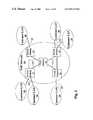
- FIG. 1is a block schematic diagram of a NSP network according to an embodiment of the invention.
- FIG. 2is a block schematic diagram of an access switch of the network of FIG. 1 ;
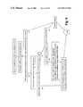
- FIG. 3is flow chart illustrating operation of an encapsulation/decapsulation device of the access switch of FIG. 1 on receipt of a data frame at a customer port of the access switch;
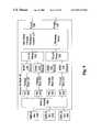
- FIG. 4is a flow chart illustrating operation of a multiplex switch of the access switch of FIG. 2 on receipt of an encapsulated data frame from the encapsulation/decapsulation device;
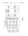
- FIG. 5is a flow chart illustrating operation of the multiplex switch of the access switch of FIG. 2 on receipt of an encapsulated data frame from another switch on a trunk;
- FIG. 6is a flow chart illustrating operation of the encapsulation/decapsulation device on receipt of an encapsulated data frame from the multiplex switch;
- FIG. 7is a block schematic diagram showing a first embodiment 42 of an access switch adapted to support connection of the NSP network to ISP routers;
- FIG. 8is a flow chart illustrating aspects of the operation of a VLAN demultiplexer of the access switch of FIG. 7 ;
- FIG. 9is a block schematic diagram showing a second embodiment 42 of an access switch adapted to support connection of the NSP network to ISP routers.
- FIG. 10is a block schematic diagram showing a third embodiment of an access switch 62 adapted to support connection of the NSP network to ISP routers.
- FIG. 1is a block schematic diagram of a NSP network 10 according to an embodiment of the invention.
- the NSP network 10comprises a plurality of routing devices in the form of access switches 12 interconnected via transmission facilities 14 .
- one or more core switches 16may be connected between some of the access switches 12 .
- the access switches 12are each connected to one or more customer LANs 20 via respective access links 22 .
- FIG. 2is a block schematic diagram of an access switch 12 of the network of FIG. 1 according to a first embodiment of the invention.
- the access switch 12comprises a plurality of address assigners in the form of Encapsulation/Decapsulation Devices (EDDs) 120 , each of which is connected to one or more customer ports 123 of the access switch 12 via a respective virtual customer access switch 124 .
- All customer ports 123 associated with a particular EDD 120 and its customer access switch 124are connected to the same customer LAN 20 via one or more access links 22 —i.e. no customer access switch 124 or EDD 120 has customer ports 123 connected to the customer LANs 20 of more than one customer.
- the physical customer ports 123map one-to-one onto respective virtual ports 122 .
- Each customer access switch 124uses IEEE 802.1 protocols to communicate with the customer LAN 20 to which it is connected via the customer port(s) 123 .
- the EDDs 120are also connected to trunks 126 of the access switch 12 via a router in the form of a virtual multiplex switch 127 which operates according to IEEE 802.1D/Q protocols adapted to handle a longer than standard data frame as will be explained below.
- Each EDD 120maintains a respective Destinations Address Association Table (DAAT) which maps Medium Access Control (MAC) addresses of elements of the customer LANs 20 in Destination Address (DA) fields onto corresponding customer port addresses in Decapsulation Egress Address (DEA) fields.
- DAATDestinations Address Association Table
- MACMedium Access Control
- DEADecapsulation Egress Address
- Each DAis mapped onto a single DEA, but each DEA may be mapped onto a plurality of DAs.
- Each customerhas a unique set of DEAs corresponding to the virtual ports 122 and the associated customer ports 123 connected to that customer's private networks. If distinct customers use the same DA, that DA will be mapped onto a different DEA in the distinct DAATs used for these customers.
- a typical customerwill have customer LANs 20 using IEEE 802.1 protocols at more than one site and will want to exchange data packets in the form of IEEE 802.3 data frames between elements of the LANs 20 at different sites.
- customersmay subscribe to a Carrier Virtual LAN (CVLAN) service provided by the NSP using the NSP network 10 .
- the CVLAN serviceprovides transparent LAN connectivity between customer LANs at different sites with full isolation between the virtual private LANs (or CVLANs) of many distinct customers.
- An IEEE 802.3 data framehas a header comprising a Destination Address (DA) identifying a LAN element for which the data frame is intended and a Source Address (SA) identifying the LAN element from which the data frame is sent.
- DADestination Address
- SASource Address
- the access switch 12receives the frame via a customer port 123 connected to the customer LAN 20 at the other site and routes the frame via the associated virtual port 122 and the customer access switch 124 to the EDD for that customer at that access switch 12 .
- FIG. 3is flow chart illustrating operation of the EDD 120 on receipt of the data frame via the customer port 122 .
- the EDD 120searches its DAAT for the DA of the received frame. If the DA is in the DAAT, the EDD 120 reads the DEA corresponding to the DA from the DAAT 129 . If the DEA corresponds to the customer port 123 on which the frame was received, the frame is intended for an element of the customer's LAN 20 on which the frame was sent. In this case, the EDD 120 discards the frame since no transmission of the frame across the NSP network 10 is required.
- the frameis intended for the customer's LAN 20 at another site.
- the frameis encapsulated by adding an additional header that includes the DEA and an Encapsulation Ingress Address (EIA) set equal to the address of the customer port 123 on which the frame was received.
- EIAEncapsulation Ingress Address
- the DEAis used to route the encapsulated frame through the NSP network 10 to a virtual port 122 and its associated customer port 123 .
- the customer port 123has an address corresponding to the DEA, and is connected to the customer LAN 20 on which the DA will be found.
- the EDD 120is unable to map the DA onto a corresponding DEA to rotate the frame across the NSP network 10 .
- the EDD 120encapsulates the frame with the DEA set to a CVLAN Broadcast Address (CBA) which enables the frame to be routed to all access switches 12 serving the CVLAN.
- CBACVLAN Broadcast Address
- the CBAcan be made specific to that customer so that the frame is routed only to virtual ports 122 and associated customer ports 123 connected to sites of that customer.
- the EDD 120sets the DEA equal to a multicast egress address.
- This multicast egress addressmay correspond to the CBA of the CVLAN if multiple multicast groups within the CVLAN are not supported, or may correspond to a multicast address that is particular to the multicast group within the CVLAN if multiple multicast groups with the CVLAN are supported.
- Such egress address assignmentsmay be arranged through suitable entries in the DAAT or by other means.
- the EDDdetermines whether that entry is missing from the DAAT by searching for the SA of the received frame in the DA fields of the DAAT. If the SA is found, the entry already exists. However, if the SA is not found, the EDD adds an entry to the DAAT, the entry having the SA of the received frame in the DA field and the address of the customer port 122 in the DEA field.
- the EDD 120may encapsulate the frame with an Encapsulating VLAN tag (EVTAG) field similar to the VLAN tag of a standard IEEE 802.3 frame.
- EVTAG fieldmay contain a 12 bit VLAN identifier and a 3 bit Quality of Service (QoS) indicator.
- the framemay also be encapsulated with a Header Checksum, a 32 bit value that will produce an all 1's value in a Cyclic Redundancy Check (CRC) register when a standard IEEE 802.3 checksum CRC procedure is applied to the encapsulation header including the Header Checksum.
- the all 1's valueis the normal starting value for the CRC register in the IEEE 802.3 checksum procedure.
- the presence of this value in the CRC register at the end of the Header Checksummeans that the IEEE 802.3 Checksum field, that was calculated and appended to the unencapsulated frame when the unencapsulated frame was created, can be used unchanged to protect the whole encapsulated frame during transmission through the NSP network 10 . Consequently, IEEE 802.1D bridging can be used to forward encapsulated frames, provided only that the multiplex switches 127 are adapted to handle frames longer than standard IEEE 802.3 frames while preserving and using the Checksum values calculated at creation of the unencapsulated frames.
- CRCCyclic Redundancy Check
- FIG. 4is a flow chart illustrating operation of the multiplex switch 127 on receipt of an encapsulated frame from the EDD 120 .
- the multiplex switch 127is similar to a IEEE 802.1D/Q switch adapted to handle the increased length of the encapsulated frame and to operate on the added header.
- the multiplex switch 127On receipt of an encapsulated frame, the multiplex switch 127 reads the DEA from the header of the encapsulated frame and determines whether the DEA is a CBA. If the DEA is not a CBA, the multiplex switch 127 finds trunk 126 corresponding to the DEA in a routing table and forwards the encapsulated frame to that trunk 126 . If the DEA is a CBA or a multicast egress address, the multiplex switch determines which trunks are registered for that CBA and forwards the encapsulated frame to all trunks 126 registered for that CBA. (The process of trunk registration is described in greater detail below.)
- Any core switches 16 in the NSP network 10operate essentially as described above for the multiplex switch 127 on receipt of an encapsulated frame at a trunk of the core switch 16 .
- FIG. 5is a flow chart illustrating operation of the multiplex switch 127 on receipt of an encapsulated data frame from another switch of the NSP network 10 on a trunk 126 of the multiplex switch 127 .
- the multiplex switch 127reads the DEA from the header of the encapsulated frame. If the DEA is not a CBA, the multiplex switch 127 finds the EDD 120 corresponding to the DEA in a routing table and forwards the encapsulated frame to that EDD 120 . If the DEA is a CBA, the multiplex switch 127 finds all EDDs 120 corresponding to the CBA and floods the encapsulated frame to all EDDs 120 corresponding to the CBA.
- FIG. 6is a flow chart illustrating operation of the EDD 120 on receipt of an encapsulated data frame from the multiplex switch 127 .
- the EDD 120reads the DEA from the encapsulated frame and compares the DEA to the addresses of the customer ports 122 connected to the EDD 120 via the customer access switch 124 . If the DEA matches the address of a customer port 123 connected to the EDD 120 , the EDD 120 decapsulates the frame by removing the header containing the DEA and the EIA, and routes the decapsulated frame to the customer port 123 via the customer access switch 124 and the virtual port 122 .
- the EDD 120determines whether the DEA is a CBA for the EDD 120 . If the DEA is a CBA for the EDD 120 , the EDD 120 decapsulates the frame by removing the header containing the DEA and the EIA, and routes the decapsulated frame to all customer ports 123 corresponding to the CBA.
- the frameis not forwarded to any customer port 123 .
- the EDD 120also assesses whether the received encapsulated frame contains information that can be used to augment the DAAT. In particular, the EDD 120 searches for the SA of the received encapsulated frame in the DA fields of the DAAT. If the SA is found, the entry already exists. However, if the SA is not found, the EDD adds an entry to the DAAT, the entry having the SA of the received frame in the DA field and the EIA of the encapsulated frame in the DEA field.
- a typical IEEE 802.3 frameis routed across the NSP network 10 from a first site of a customer LAN 20 to a second site of the customer LAN 20 as follows:
- the access switch 12 receiving the frame from the first site of the customer LAN 20is unable to determine the DEA from the DA of the received frame, the frame is flooded across the network to all sites of the customer LAN 20 as follows:
- IEEE 802.3 frames having a multicast address in the DA fieldare encapsulated with the CBA in the DEA field and are flooded across the NSP network 10 from the first access switch to all access switches 12 serving sites of the customer LAN 20 .
- the DEAs used for a particular customerare unique to that customer because of the technique used to fill the DAAT at each EDD 120 .
- Each EDD 120is assigned to a single customer and serves only virtual ports 122 and associated customer ports 123 which are assigned that customer.
- the DEA of that entrymust be the DEA of the customer port 122 which is uniquely assigned to that customer.
- an EDD 120When an EDD 120 receives an encapsulated frame from the multiplex switch 127 , it verifies that the frame has a DEA corresponding to a connected customer port 123 or a CBA corresponding to its assigned customer to ensure that the frame comes from within the CVLAN of its customer before adding any entry to its DAAT. Such an entry must include the EIA of the frame in the DEA field, and that EIA corresponds to a customer port 122 that is assigned to the same customer—otherwise the received frame would not have a DEA or CBA corresponding to that customer.
- each customerhas a CVLAN that is isolated from the CVLANs of other customers.
- the NSP network 10can provide a very large number of isolated CVLANs to serve a very large number of customers because the isolation between CVLANs is determined by unique sets of virtual ports and associated broadcast addresses rather than by a more limited number of CVLAN identifiers.
- the virtual ports 122 and associated customer ports 123 , the customer access switches 124 , the EDDs 120 and the DAATsare dedicated to specific customers.
- the multiplex switches 127 , core switches 16 and transmission facilities 14are shared among many customers for economies of scale.
- key elements of the customer access switches 124 , multiplex switches 127 and core switches 16can be provided using proven IEEE 802.1D/Q hardware and software with relatively minor modifications for further cost advantages.
- the extensive use of modified IEEE 802.1D/Q techniques in this embodiment of the NSP network 10also ensures that extensive industry experience in operating IEEE 802.1 networks can be applied readily to the operation of this network.
- IEEE 802.1Ddefines procedures for registering multicast groups at trunks such that frames carrying a particular multicast address in the DA field are forwarded only by trunks which have that multicast address registered for that trunk.
- the multicast group registrationsare propagated by the IEEE 802.1D GARP Multicast Registration Protocol (GMRP) to all trunks in the network needed to create a minimal subset of interconnections that interconnects all registrants to the group.
- GMRPGARP Multicast Registration Protocol
- Each EDD 120registers a corresponding CBA at its multiplex switch port so that encapsulated frames having a particular CBA in the DEA field will be transmitted over only those trunks needed to transmit the frame to the other EDDs 120 of the particular CVLAN corresponding to the CBA. This avoids wasteful transmission of frames to EDDs 120 that are not participating in the CVLAN.
- all frames having a multicast DAmay be assigned a selected CBA for a DEA, the CBA being selected according to the ingress port at which the frame was received. While this procedure restricts frames to the CVLANs for which they are intended, it does not enable customers to restrict multicast frames to distinct multicast groups within their CVLANs.
- Distinct multicast groups within CVLANscan be supported by defining a distinct multicast DEA for each such multicast group.
- the multicast DEAsmust be unique to the CVLAN to which the multicast group belongs, and the EDDs 120 must translate multicast DAs of unencapsulated frames entering the NSP network 10 into the appropriate multicast DEAs using the DAATs or some other means.
- the multicast DEAsshould be locally administered by the NSP.
- each multicast DEAcan ensure that each multicast DEA is unique to a particular CVLAN within the NSP network 10 is by requiring a multicast DEA format that combines a CVLAN identifier with a multicast group identifier.
- each multicast DEAcould comprise:
- the local administration bitcan be used to detect frames bearing multicast addresses that are not locally administered so that such frames can be discarded to ensure that isolation between distinct CVLANs is preserved.
- the multicast group identifiercan be the multicast DA or an identifier derived from the multicast DA. Because the multicast DEAs include a CVLAN identifier, the same multicast DAs can be used in distinct CVLANs without loss of isolation between distinct CVLANs.
- the CBA for a particular CVLANcould comprise:
- the IEEE 802.1D CARP Multicast Registration. Protocolreferenced above can be modified for NSP networks 10 supporting multicast groups within CVLANs to create a minimal subset of interconnections that interconnects all registrants to the multicast group.
- the GMRPis modified to ensure that GMRP messages related to multicast DEAs other than CBAs are transmitted and create trunk registrations only on trunks registered for the CBA of the CVLAN to which the multicast DEA belongs. Consequently, GMRP message activity for multicast DEAs other than CBAs are confined to the physical topology in which messages addressed by the CBA can propagate.
- GMRP messages required for the registration of CBAsare not so confined, but such messages are infrequent because new registrations for CBAS occur only when a new customer site is configured.
- a frame bearing a multicast DEA other than a CBAmay be transmitted on a trunk only if the trunk has received a GMRP group registration generated by a GMRP application from another switch.
- Thisis the fundamental multicast tree pruning rule of IEEE 802.1D “extended filtering” This technique achieves bandwidth savings by ensuring that multicast frames are transmitted on trunks only if a station that can be reached on that trunk has indicated an interest in receiving multicasts from that multicast group.
- EDDs 120 of the NSP network 10must translate IGMP join requests entering the NSP network 10 into GMRP join requests for forwarding into the NSP network 10 according to the modified GMRP procedures described above.
- each CVLANis defined by a distinct set of virtual ports 122 have a one-to-one mapping to a respective distinct set of customer ports 123 having physical addresses defining a distinct set of respective egress addresses.
- each CVLANwould require a separate physical port and transmission link for connection to each ISP router to which connection of the CVLAN is required.
- FIG. 7is a block schematic diagram showing a first embodiment 22 of an access switch adapted to support connection of the NSP network 10 to ISP routers 300 , 302 .
- the ISP routers 300 , 302are IEEE 802.1 routers that use VLAN tags to separate CVLANs.
- the access switch 22comprises a plurality of address assigners in the form of EDDs 120 and a router in the form of a virtual multiplex switch 127 as did the access switch 12 .
- the access switch 22further comprises a plurality of VLAN demultiplexers 222 connected between the multiplex switch 127 and groups of the EDDs 120 , each VLAN demultiplexer 222 being associated with a respective egress address or a respective distinct set of egress addresses.
- Each EDD 120is connected to a respective virtual port 122 .
- a respective VLAN translator 224is connected to each virtual port 122 , and each group of VLAN translators 224 is connected to a respective router demultiplexer 226 .
- the router demultiplexers 226are connected to external ISP routers 300 , 302 .
- the virtual multiplex switch 127On receipt of an encapsulated packet having an egress address corresponding to one of the external routers 300 , 302 via a trunk 126 , the virtual multiplex switch 127 routes the encapsulated packet to a VLAN demultiplexer 222 selected according to the egress address.
- the selected VLAN demultiplexer 222routes the encapsulated packet to an EDD 120 selected according to the ingress address of the encapsulated packet.
- This selection schemeensures that all encapsulated packets having a common egress address and an ingress address corresponding to a virtual port 122 in a particular set of the distinct sets of virtual ports 122 are routed to an EDD 120 associated with that egress address and that particular distinct set of virtual ports 122 .
- the VLAN demultiplexer 222uses the ingress address of the packet to determine which EDD 120 should process the packet since the ingress address does uniquely identify the CVLAN to which the packet is restricted. However, when the egress address is a broadcast or multicast egress address employing the format described above for broadcast and multicast egress addresses, the VLAN demultiplexer 222 may determine which EDD 120 to route the packet to, either from the egress address or from the ingress address.
- Each VLAN demultiplexer 222may maintain a table for associating ingress addresses with EDDs 120 and may employ that table to determine the routing of packets to EDDs 120 .
- the VLAN demultiplexers 222may use the ingress addresses and egress addresses of broadcast and multicast packets to populate the table.
- a VLAN demultiplexer 222may create a new entry having the ingress address in an ingress address field of the table and an EDD identifier determined from the broadcast or multicast egress address of the packet.
- FIG. 8is a flow chart illustrating operation of the VLAN demultiplexers 222 on receipt of a packet from the multiplex switch 127 in more detail.
- the selected EDD 120decapsulates the packet and forwards it via the respective virtual port 122 to the respective VLAN translator 224 .
- the VLAN translator 224applies a respective VLAN identifier to the packet.
- the VLAN identifiercorresponds to the distinct set of ports containing the ingress port, i.e. it is particular to the CVLAN which corresponds to that distinct set of ports
- the VLAN translator 224forwards the resulting packet to the router demultiplexer 226 .
- the VLAN translators 224may receive broadcast packets for VLANs to which are not supported by the ISP routers 300 , 302 .
- the VLAN translators 224discard such packets.
- the router demultiplexer 226routes the packet to an IEEE 802.1 external router 300 .
- the external router 300preserves isolation of CVLANs using VLAN identifiers according to the IEEE 802.1 standard.
- the router demultiplexer 226On receipt of a packet from one of the external routers 300 , the router demultiplexer 226 routes the packet to VLAN translator 224 selected according to a VLAN identifier of the received packet.
- the VLAN translator 224forwards the packet to its respective EDD 120 .
- the EDD 120encapsulates the packet with an ingress address corresponding to its respective virtual port 122 and an egress address corresponding to its destination address, and forwards the encapsulated packet to the VLAN demultiplexer 222 .
- the VLAN demultiplexer 222forwards the encapsulated packet to the virtual multiplex switch 127 for routing according to the egress address.
- the arrangement described aboveenables a particular CVLAN within the network 10 to be mapped onto one VLAN identifier in a first IEEE 802.1 VLAN identifier space supported by a first external router 300 or plurality of routers 300 .
- the same CVLAN within the network 10may be mapped onto another VLAN identifier in a second IEEE 802.1 VLAN identifier space supported by a second external router 302 or plurality of routers 302 , so assignment of VLAN identifiers in distinct external IEEE 802.1 VLAN networks need not be coordinated.
- the arrangement described aboveenables the same VLAN identifier indifferent IEEE 802.1 VLAN identifier spaces to be mapped onto different CVLANs in the network 10 . This is advantageous because, as noted above, each IEEE 802.1 VLAN identifier space is limited to 4095 distinct VLANS, whereas the network 10 can support many times that number of CVLANs.
- the virtual ports 122have the same properties as the virtual ports 122 of the embodiment of FIG. 2 .
- each CVLANhas a distinct set of virtual ports 122 , no virtual port 122 belonging to more that one of the distinct sets.
- each customercan choose his router-access VLAN identifiers arbitrarily. There is no requirement that VLAN identifier choice be coordinated between multiple customers.
- Each ISP router 300 , 302participates in only one VLAN identifier space.
- the access switch 22translates VLAN identifiers between this one VLAN identifier space and the many VLAN identifier spaces of the NSF network 10 .
- the NSP network 10has one VLAN identifier space for each distinct CVLAN.
- Each ISP router 300 , 302may either share a VLAN identifier space with one or more other routers belonging to the same ISP or have its own dedicated VLAN identifier space.
- the NSPmust establish an association between each customer VLAN requiring ISP router access and a unique VLAN in each ISP router VLAN identifier space This association requires a three-way agreement between the customer, the NSP and the ISP, as follows:
- FIG. 9is a block schematic diagram showing a second embodiment 42 of an access switch adapted to support connection of the network 10 to ISP routers 500 , 502 .
- the ISP routers 500 , 502are MPLS routers providing multiple virtual router capability.
- the access switch 42comprises a plurality of address assigners in the form of EDDs 120 and a router in the form of a virtual multiplex switch 127 as did the access switches 12 , 22 .
- the access switch 42further comprises a plurality of VLAN demultiplexers 222 connected between the multiplex switch 127 and groups of the EDDs 120 , each VLAN demultiplexer 222 being associated with a respective egress address as in the access switch 22 .
- Each EDD 120is connected to a respective virtual port 122 .
- a respective Multi-Protocol Label Switching (MPLS) converter 424is connected to each virtual port 122 , and the MPLS converters 424 are connected to a MPLS switch 426 .
- MPLSMulti-Protocol Label Switching
- the virtual multiplex switch 127On receipt of an encapsulated packet on a trunk 126 , the virtual multiplex switch 127 routes the encapsulated packet to a VLAN demultiplexer 222 selected according to the egress address.
- the selected VLAN demultiplexer 222routes the encapsulated packet to an EDD 120 selected according to the ingress address of the encapsulated packet.
- This selection schemeensures that all encapsulated packets having a common egress address and an ingress address corresponding to a virtual port 122 in a particular set of the distinct sets of virtual ports 122 are routed to an EDD 120 associated with that egress address and that particular distinct set of virtual ports 122 .
- the selected EDD 120decapsulates the packet and forwards it via the respective virtual port 122 to the respective MPLS converter 424 .
- the MPLS converter 424applies a respective MPLS label to the packet.
- the MPLS labelcorresponds to the distinct set of virtual ports 122 containing the ingress virtual port 122 , i.e. it is particular to the CVLAN which corresponds to that distinct set of virtual ports.
- the MPLS converter 424forwards the resulting packet to the MPLS switch 426 .
- the MPLS switch 426routes the packet to an external router 500 .
- the external router 500preserves isolation of CVLANs using the MPLS labels that are unique to CVLAN.
- the MPLS switch 426On receipt of a packet from one of the external routers 500 , the MPLS switch 426 routes the packet to a MPLS converter 424 selected according to a MPLS label of the received packet.
- the MPLS converter 424forward the packet to its respective EDD 120 via its respective virtual port 122 .
- the EDD 120encapsulates the packet with an ingress address corresponding to its respective virtual port 122 and an egress address corresponding to its destination address, and forwards the encapsulated packet to the VLAN demultiplexer 222 .
- the VLAN demultiplexer 222forwards the encapsulated packet to the virtual multiplex switch 127 for routing according to the egress address.
- the arrangement described aboveenables a particular CVLAN within the network 10 to be mapped onto one MPLS label in a first MPLS label space supported by a first external router 500 or plurality of routers 500 .
- the same CVLAN within the network 10may be mapped onto another MPLS label in a second MPLS label space supported by a second external router 502 or plurality of routers 502 .
- FIG. 10is a block schematic diagram showing a third embodiment of an access switch 62 adapted to support connection of the network 10 to ISP routers 700 .
- the access switch 62comprises a plurality of address assigners in the form of EDDs 120 and a router in the form of a virtual multiplex switch 127 as did the access switches 12 , 22 , 42 .
- the access switch 62further comprises a plurality of VLAN demultiplexers 222 connected between the multiplex switch 127 and groups of the EDDs 120 , each VLAN demultiplexer 222 being associated with a respective egress address as in the access switches 22 , 42 .
- Each EDD 120is connected to a respective virtual port 122 .
- a respective virtual private router 624is connected to each virtual port 122 , and each virtual private router 624 is connected to respective network address translator 626 .
- the virtual multiplex switch 127On receipt of an encapsulated packet on a trunk 126 , the virtual multiplex switch 127 routes the encapsulated packet to a VLAN demultiplexer 222 selected according to the egress address.
- the selected VLAN demultiplexer 222routes the encapsulated packet to an EDD 120 selected according to the ingress address of the encapsulated packet.
- This selection schemeensures that all encapsulated packets having a common egress address and an ingress address corresponding to a virtual post 122 in a particular set of the distinct sets of virtual ports 122 are routed to an EDD 120 associated with that egress address and that particular distinct set of virtual ports 122 .
- the selected EDD 120decapsulates the packet and forwards it via the respective virtual port 122 to the respective virtual private router 624 .
- the virtual private router 624discards any packets not having a destination IF address corresponding to the router 700 connected to the respective network address translator 626 , and forwards any packets having a destination address corresponding to the router 700 to the respective network address translator 626 .
- the network address translator 626translates the destination address from a private IP address in the customer's private IP address space to a corresponding public IP address in the public IP address space.
- the network address translator 626forwards the packet with the translated IP address to the router 700 .
- a network address translator 626On receipt of a packet from one of the external routers 700 , a network address translator 626 translates the destination address of the received packet from a public IP address to a corresponding private IP address in the private IP address space of the NSP network 10 .
- the network address translator 626forwards the packet with the translated IP address to its respective virtual private router 624 .
- the virtual private router 624applies a corresponding MAC destination address to the packet in the DA field and forwards the resulting packet to its respective EDD 120 via its respective virtual port 122 .
- the EDD 120encapsulates the packet with an ingress address corresponding to its respective virtual port 122 and an egress address corresponding to its destination address, and forwards the encapsulated packet to the VLAN demultiplexer 222 .
- the VLAN demultiplexer 222forwards the encapsulated packet to the virtual multiplex switch 127 for routing according to the egress address.
- one or more of the IP routerscould be integrated into the access switch 62 to provide an IP router appropriate for direct connection to the NSP network 10 .
- Some or all of the network address translators 626 of FIG. 10could be eliminated if the IP addresses corresponding to one or more of the virtual private networks in the NSP network are registered as public IP addresses.
- each distinct set of virtual ports 122 defining a virtual private networkmay include some virtual ports 122 which map one-to-one onto corresponding physical ports, such as the customer ports 123 of the FIG. 2 embodiment.
- the physical portsare each associated with a unique respective physical address.
- Other groups of virtual ports 122may be connected to a common physical port for each group.
- Each such virtual port 122is associated with a unique combination of the physical address of the common physical port and some other identifier that identifies the virtual private network with which the virtual port 122 is associated.
- the other identifiermay be one or more of an ingress address, a virtual private network identifier, a VLAN identifier, an MPLS label or any other identifier sufficient to unambiguously determine the virtual private network with which the virtual port 122 is associated.
Landscapes
- Engineering & Computer Science (AREA)
- Computer Networks & Wireless Communication (AREA)
- Signal Processing (AREA)
- Computer Security & Cryptography (AREA)
- Data Exchanges In Wide-Area Networks (AREA)
- Small-Scale Networks (AREA)
Abstract
Description
- 1. The IEEE 802.1 frame is routed by the
customer LAN 20 at the first site to afirst access switch 12 serving the first site based on the DA of the frame. - 2. The IEEE 802.3 frame is encapsulated at the
first access switch 12 by adding a header comprising a DEA specifying a port on asecond access switch 12 serving the second site of thecustomer LAN 20. - 3. The encapsulated frame is routed across the
NSP network 10 from thefirst access switch 12 to thesecond access switch 12 based on the DEA of the encapsulated frame. 4. The encapsulated frame is decapsulated by the second access switch32 and forwarded to the second site of the customer LAN where it is routed based on the DA of the decapsulated frame.
- 1. The IEEE 802.3 frame is routed by the
customer LAN 20 at the first site to afirst access switch 12 serving the first site based on the DA of the frame. - 2. The IEEE 802.3 frame is encapsulated at the
first access switch 12 by adding a header comprising a CBA in the DEA field. - 3. The encapsulated frame is flooded across the
NSP network 10 from thefirst access switch 12 to all access switches12 serving sites of thecustomer LAN 20 based on the CBA of the encapsulated frame. - 4. The encapsulated frame is decapsulated by the destination access switches12 and forwarded to the other sites of the customer LAN where it is routed based on the DA of the decapsulated frame.
- 1. a multicast bit (indicating whether the address is a unicast address or a multicast address),
- 2. a local administration bit (indicating whether the address is locally administered),
- 3. a CVLAN identifier (identifying the CVLAN to which the packet is to be restricted),
- 4. an IP multicast bit (indicating whether the multicast is an IP multicast), and
- 5. a multicast group identifier (identifying the multicast group within the CVLAN to which the packet is to be restricted).
- 1. a 1 for the multicast bit,
- 2. a 1 for the local administration bit,
- 3. the CVLAN identifier for the particular CVLAN′
- 4. a 0 for the IP multicast bit, and
- 5. a field of O's for the multicast group identifier.
- 1. The ISP needs to know, for each customer, which subnets are to be supported. The NSP decides which of his VLAN identifiers he will assign to each subnet.
- 2. Each customer needs to know the subnet mask and router IP address for each subnet and which of his VLAN identifiers he will assign to each subnet.
- 3. The NSP needs to know the pairing of VLANs created by the decisions taken by the ISP and the customer to support the subnet. The VLAN pairing created for each subnet must be configured in the VLAN translating
access switch 22 so that VLAN identifiers may be modified in packets passing between router access VLAN identifier spaces and customer VLAN identifier spaces.
Claims (56)
Priority Applications (7)
| Application Number | Priority Date | Filing Date | Title |
|---|---|---|---|
| US09/270,733US6937574B1 (en) | 1999-03-16 | 1999-03-16 | Virtual private networks and methods for their operation |
| CA002296646ACA2296646C (en) | 1999-03-16 | 2000-01-20 | Virtual private networks and methods for their operation |
| AU14808/00AAU1480800A (en) | 1999-03-16 | 2000-01-31 | Virtual private networks and methods for their operations |
| US09/513,244US6788681B1 (en) | 1999-03-16 | 2000-02-25 | Virtual private networks and methods for their operation |
| EP00302012AEP1045553B1 (en) | 1999-03-16 | 2000-03-13 | Virtual private networks and methods for their operation |
| DE60025437TDE60025437T2 (en) | 1999-03-16 | 2000-03-13 | Private virtual networks and methods of their operation |
| JP2000071518AJP4355422B2 (en) | 1999-03-16 | 2000-03-15 | Method and apparatus for routing packets |
Applications Claiming Priority (1)
| Application Number | Priority Date | Filing Date | Title |
|---|---|---|---|
| US09/270,733US6937574B1 (en) | 1999-03-16 | 1999-03-16 | Virtual private networks and methods for their operation |
Related Child Applications (1)
| Application Number | Title | Priority Date | Filing Date |
|---|---|---|---|
| US47504299AContinuation-In-Part | 1999-03-16 | 1999-12-30 |
Publications (1)
| Publication Number | Publication Date |
|---|---|
| US6937574B1true US6937574B1 (en) | 2005-08-30 |
Family
ID=23032570
Family Applications (1)
| Application Number | Title | Priority Date | Filing Date |
|---|---|---|---|
| US09/270,733Expired - LifetimeUS6937574B1 (en) | 1999-03-16 | 1999-03-16 | Virtual private networks and methods for their operation |
Country Status (6)
| Country | Link |
|---|---|
| US (1) | US6937574B1 (en) |
| EP (1) | EP1045553B1 (en) |
| JP (1) | JP4355422B2 (en) |
| AU (1) | AU1480800A (en) |
| CA (1) | CA2296646C (en) |
| DE (1) | DE60025437T2 (en) |
Cited By (75)
| Publication number | Priority date | Publication date | Assignee | Title |
|---|---|---|---|---|
| US20010047414A1 (en)* | 2000-05-29 | 2001-11-29 | Yoon Ki J. | Dedicated private network service method having backup and loads-balancing functions |
| US20020022483A1 (en)* | 2000-04-18 | 2002-02-21 | Wayport, Inc. | Distributed network communication system which allows multiple wireless service providers to share a common network infrastructure |
| US20020037010A1 (en)* | 2000-09-28 | 2002-03-28 | Nec Corporation | MPLS-VPN service network |
| US20020067725A1 (en)* | 2000-12-06 | 2002-06-06 | Naoki Oguchi | Virtual network construction method, system, and relaying apparatus |
| US20020133582A1 (en)* | 2000-12-21 | 2002-09-19 | Atsushi Shibata | Network management system |
| US20030053450A1 (en)* | 2001-09-18 | 2003-03-20 | Makoto Kubota | Layer 2-VPN relay system |
| US20030112809A1 (en)* | 2001-08-24 | 2003-06-19 | Bharali Anupam A. | Efficient method and system for automatic discovery and verification of optimal paths through a dynamic multi-point meshed overlay network |
| US20030126291A1 (en)* | 2001-12-28 | 2003-07-03 | Wang Ben B. | Method and message distributor for routing requests to a processing node |
| US20030147402A1 (en)* | 2002-02-05 | 2003-08-07 | Brahim Hamid Ould | Technique for implementing a multi-service packet and optical /TDM virtual private cross-connect |
| US20030210671A1 (en)* | 2002-05-08 | 2003-11-13 | Siemens Canada Limited | Local area network with wireless client freedom of movement |
| US20040028058A1 (en)* | 2002-08-07 | 2004-02-12 | Allied Telesis K.K. | Transmission system and method thereof |
| US20040047320A1 (en)* | 2002-09-09 | 2004-03-11 | Siemens Canada Limited | Wireless local area network with clients having extended freedom of movement |
| US20040066781A1 (en)* | 2002-10-07 | 2004-04-08 | Broadcom Corporation | Fast-path implementation for an uplink double tagging engine |
| US20040078469A1 (en)* | 2002-06-04 | 2004-04-22 | Prashanth Ishwar | Managing VLAN traffic in a multiport network node using customer-specific identifiers |
| US20040193677A1 (en)* | 2003-03-24 | 2004-09-30 | Shaul Dar | Network service architecture |
| US20050073994A1 (en)* | 2001-08-31 | 2005-04-07 | Mathias Franz | Arrangement for the provision of messages and dialogues in packet networks |
| US20050089028A1 (en)* | 2003-10-27 | 2005-04-28 | Marconi Communications, Inc. | Method and system for managing computer networks |
| US20050117534A1 (en)* | 1999-10-06 | 2005-06-02 | Jan Vancraeynest | Apparatus for handover in TDMA communications |
| US20050190793A1 (en)* | 2003-12-16 | 2005-09-01 | Alcatel | System comprising a terminal system, an access multiplexer and a network |
| US20060007917A1 (en)* | 2004-07-07 | 2006-01-12 | Masahiro Saito | Frame transfer method and edge switch |
| US20060040664A1 (en)* | 2004-07-13 | 2006-02-23 | Murray Richard J | Communications systems |
| US20060092868A1 (en)* | 2000-11-22 | 2006-05-04 | Meier Robert C | Point-controlled contention arbitration in multiple access wireless LANs |
| US7072964B1 (en)* | 1999-08-31 | 2006-07-04 | Science Applications International Corporation | System and method for interconnecting multiple virtual private networks |
| US20060155872A1 (en)* | 2002-08-21 | 2006-07-13 | Siemens Aktiengesellschaft | Efficient intra-domain routing in packet-switched networks |
| US20060221953A1 (en)* | 2005-04-01 | 2006-10-05 | Claude Basso | Method and apparatus for blind checksum and correction for network transmissions |
| US20060221989A1 (en)* | 2005-04-01 | 2006-10-05 | Claude Basso | Method and system for accommodating several ethernet ports and a wrap transmitted flow handled by a simplifed frame-by-frame upper structure |
| US20060221859A1 (en)* | 2005-03-31 | 2006-10-05 | Bijwaard Dennis Johannes A | Method and apparatus for managing a multicast tree |
| US20060221977A1 (en)* | 2005-04-01 | 2006-10-05 | International Business Machines Corporation | Method and apparatus for providing a network connection table |
| US20060221952A1 (en)* | 2005-04-01 | 2006-10-05 | Claude Basso | System and method for parsing, filtering, and computing the checksum in a host ethernet adapter (HEA) |
| US20060221961A1 (en)* | 2005-04-01 | 2006-10-05 | International Business Machines Corporation | Network communications for operating system partitions |
| US20060222002A1 (en)* | 2005-04-01 | 2006-10-05 | International Business Machines Corporation | Configurable ports for a host Ethernet adapter |
| US20060251120A1 (en)* | 2005-04-01 | 2006-11-09 | Arimilli Ravi K | Host ethernet adapter for networking offload in server environment |
| US20070115151A1 (en)* | 2000-07-25 | 2007-05-24 | Juniper Networks, Inc. | System and method for incremental and continuous data compression |
| US20070127473A1 (en)* | 2005-12-01 | 2007-06-07 | Andrew Kessler | Interdomain bi-directional protocol independent multicast |
| US20070147363A1 (en)* | 2005-12-23 | 2007-06-28 | Oswal Anand K | Network edge device configured for adding protocol service header identifying service encoding of IP packet payload |
| US20070217415A1 (en)* | 2006-03-16 | 2007-09-20 | Ijsbrand Wijnands | System and method for implementing multicast over a label-switched core network |
| US20070258446A1 (en)* | 2006-05-02 | 2007-11-08 | Cisco Technology, Inc., A California Corporation | Support of a large number of VLANs in a bridged network |
| US20080016191A1 (en)* | 2006-07-11 | 2008-01-17 | Dennis Bijwaard | Method and apparatus for supporting ip multicast |
| US20080019385A1 (en)* | 2005-12-30 | 2008-01-24 | Huawei Technologies Co., Inc. (Usa) | System and method of mapping between local and global service instance identifiers in provider networks |
| US20080205402A1 (en)* | 2007-02-26 | 2008-08-28 | Mcgee Michael Sean | Network resource teaming on a per virtual network basis |
| US20080240114A1 (en)* | 2005-11-22 | 2008-10-02 | Huawei Technologies Co., Ltd. | Data Frame Forwarding Method By Data Relay Entity And Data Relay Entity |
| US20080273539A1 (en)* | 2005-04-01 | 2008-11-06 | International Business Machines Corporation | System for performing a packet header lookup |
| US7450595B1 (en)* | 2001-05-01 | 2008-11-11 | At&T Corp. | Method and system for managing multiple networks over a set of ports |
| US20080317027A1 (en)* | 2005-04-01 | 2008-12-25 | International Business Machines Corporation | System for reducing latency in a host ethernet adapter (hea) |
| US20090006603A1 (en)* | 2005-12-13 | 2009-01-01 | International Business Machines Corporation | Methods for Operating Virtual Networks, Data Network System, Computer Program and Computer Program Product |
| US7586915B1 (en)* | 2003-10-23 | 2009-09-08 | Cisco Technology, Inc. | Technique for coupling entities via virtual ports |
| US7609689B1 (en)* | 2001-09-27 | 2009-10-27 | Cisco Technology, Inc. | System and method for mapping an index into an IPv6 address |
| US20090298521A1 (en)* | 2008-06-03 | 2009-12-03 | Data Connection Limited | System and method of delivery of media data |
| US20090323985A1 (en)* | 2008-06-30 | 2009-12-31 | Qualcomm Incorporated | System and method of controlling power consumption in response to volume control |
| US20100208732A1 (en)* | 2008-12-11 | 2010-08-19 | Skype Limited | Controlling Packet Transmission |
| US20100235526A1 (en)* | 2009-03-13 | 2010-09-16 | Novell, Inc. | System and method for reducing cloud ip address utilization using a distributor registry |
| USRE41986E1 (en)* | 1999-05-07 | 2010-12-07 | At&T Intellectual Property Ii, L.P. | Method and apparatus for load-sensitive routing of long-lived packet flows |
| US20110128868A1 (en)* | 2008-12-11 | 2011-06-02 | Skype Limited | Data Rate Control Mechanism |
| CN102307144A (en)* | 2011-08-19 | 2012-01-04 | 杭州华三通信技术有限公司 | Dynamic host configuration protocol (DHCP) message forwarding method for transparent interconnection of lots of links (TRILL) network and routing bridge |
| US20120063310A1 (en)* | 2010-09-10 | 2012-03-15 | Muhammad Sakhi Sarwar | Method and system for virtualized forwarding |
| US20140122675A1 (en)* | 2012-10-29 | 2014-05-01 | Oracle International Corporation | Network virtualization over infiniband |
| CN104601477A (en)* | 2013-10-31 | 2015-05-06 | 华为技术有限公司 | Access method of TRILL (Transparent Interconnect of Lots of Links) network and route bridge equipment |
| US20150124811A1 (en)* | 2009-03-03 | 2015-05-07 | Telefonaktiebolaget L M Ericsson (Publ) | Multicast interworking systems and methods |
| US20150263990A1 (en)* | 2012-10-24 | 2015-09-17 | Nec Corporation | Network device, control method, and program |
| US9264384B1 (en) | 2004-07-22 | 2016-02-16 | Oracle International Corporation | Resource virtualization mechanism including virtual host bus adapters |
| US9331963B2 (en) | 2010-09-24 | 2016-05-03 | Oracle International Corporation | Wireless host I/O using virtualized I/O controllers |
| US9467373B2 (en) | 2003-07-29 | 2016-10-11 | Marlow Technologies, Llc | Broadband access for virtual private networks |
| US9571394B1 (en)* | 2014-01-10 | 2017-02-14 | Juniper Networks, Inc. | Tunneled packet aggregation for virtual networks |
| US9584568B2 (en) | 2012-05-09 | 2017-02-28 | Nec Corporation | Signal processing apparatus and signal processing method thereof for implementing a broadcast or a multicast communication |
| US9591104B2 (en) | 1999-12-29 | 2017-03-07 | Implicit, Llc | Method and system for data demultiplexing |
| US20170192815A1 (en)* | 2012-04-04 | 2017-07-06 | Cisco Technology, Inc. | Location-aware virtual service provisioning in a hybrid cloud environment |
| US9813283B2 (en) | 2005-08-09 | 2017-11-07 | Oracle International Corporation | Efficient data transfer between servers and remote peripherals |
| US9973446B2 (en) | 2009-08-20 | 2018-05-15 | Oracle International Corporation | Remote shared server peripherals over an Ethernet network for resource virtualization |
| US10225105B2 (en) | 2015-07-08 | 2019-03-05 | Openvpn Technologies, Inc. | Network address translation |
| EP2582099B1 (en)* | 2010-06-09 | 2021-03-17 | Nec Corporation | Communication system, logic channel control device, communication method and program |
| CN112995177A (en)* | 2021-02-25 | 2021-06-18 | 中国电子科技集团公司第五十四研究所 | Unicast addressing conversion method suitable for space-based network |
| US11089382B2 (en)* | 2018-08-08 | 2021-08-10 | Realtek Semiconductor Corporation | Multimedia streaming and network apparatus and operation method of the same |
| US11494212B2 (en)* | 2018-09-27 | 2022-11-08 | Intel Corporation | Technologies for adaptive platform resource assignment |
| US20230079949A1 (en)* | 2020-05-13 | 2023-03-16 | Huawei Technologies Co., Ltd. | Protocol Packet Processing Method, Network Device, and Computer Storage Medium |
| US12169589B1 (en)* | 2023-09-13 | 2024-12-17 | Zecurity, Llc | Apparatus and methods relying on non-flashable circuitry for improving security for a system connected to a public or private network |
Families Citing this family (38)
| Publication number | Priority date | Publication date | Assignee | Title |
|---|---|---|---|---|
| CA2388938C (en)* | 2001-06-08 | 2010-05-04 | The Distributions Systems Research Institute | Terminal-to-terminal communication connection control system for ip full service |
| DE60108404T2 (en) | 2001-12-10 | 2005-12-22 | Alcatel | Apparatus and method for aligning the multiple data traffic in an Ethernet MAN |
| WO2003067821A1 (en) | 2002-02-08 | 2003-08-14 | Telefonaktiebolaget Lm Ericsson (Publ) | Method and system relating service providers to clients, in an access network, using dynamically allocated mac addresses |
| EP1351450B1 (en)* | 2002-03-15 | 2007-05-30 | Broadcom Corporation | Fastpath implementation for transparent local area network (LAN) services over multiprotocol label switching (MPLS) |
| US7515592B2 (en) | 2002-10-07 | 2009-04-07 | Broadcom Corporation | Fast-path implementation for transparent LAN services using double tagging |
| WO2004066563A1 (en)* | 2003-01-21 | 2004-08-05 | Fujitsu Limited | Carrier network of virtual network system, and communication node of the carrier network |
| US20040225725A1 (en) | 2003-02-19 | 2004-11-11 | Nec Corporation | Network system, learning bridge node, learning method and its program |
| US7006499B2 (en)* | 2003-04-28 | 2006-02-28 | Alcatel Ip Networks, Inc. | Source identifier for MAC address learning |
| WO2004114605A1 (en)* | 2003-06-20 | 2004-12-29 | Zte Corporation | A method for ethernet network service safety isolation |
| US7301949B2 (en) | 2003-07-15 | 2007-11-27 | Telefonaktiebolaget Lm Ericsson (Publ) | Arrangements for connection-oriented transport in a packet switched communications network |
| US7978716B2 (en) | 2003-11-24 | 2011-07-12 | Citrix Systems, Inc. | Systems and methods for providing a VPN solution |
| JP2007533172A (en) | 2003-11-11 | 2007-11-15 | サイトリックス ゲートウェイズ, インコーポレイテッド | Virtual private network with fake server |
| CN1558685B (en)* | 2004-01-19 | 2010-04-28 | 中兴通讯股份有限公司 | A method for implementing cross-office wide area business group based on SPC exchange |
| US10375023B2 (en) | 2004-02-20 | 2019-08-06 | Nokia Technologies Oy | System, method and computer program product for accessing at least one virtual private network |
| US8495305B2 (en) | 2004-06-30 | 2013-07-23 | Citrix Systems, Inc. | Method and device for performing caching of dynamically generated objects in a data communication network |
| US7757074B2 (en) | 2004-06-30 | 2010-07-13 | Citrix Application Networking, Llc | System and method for establishing a virtual private network |
| US8739274B2 (en) | 2004-06-30 | 2014-05-27 | Citrix Systems, Inc. | Method and device for performing integrated caching in a data communication network |
| US7609721B2 (en) | 2004-07-23 | 2009-10-27 | Citrix Systems, Inc. | Systems and methods for adjusting the maximum transmission unit for encrypted communications |
| US8363650B2 (en)* | 2004-07-23 | 2013-01-29 | Citrix Systems, Inc. | Method and systems for routing packets from a gateway to an endpoint |
| WO2006020823A1 (en) | 2004-08-13 | 2006-02-23 | Citrix Systems, Inc. | A method for maintaining transaction integrity across multiple remote access servers |
| US8549149B2 (en) | 2004-12-30 | 2013-10-01 | Citrix Systems, Inc. | Systems and methods for providing client-side accelerated access to remote applications via TCP multiplexing |
| US8954595B2 (en) | 2004-12-30 | 2015-02-10 | Citrix Systems, Inc. | Systems and methods for providing client-side accelerated access to remote applications via TCP buffering |
| US7810089B2 (en) | 2004-12-30 | 2010-10-05 | Citrix Systems, Inc. | Systems and methods for automatic installation and execution of a client-side acceleration program |
| US8706877B2 (en) | 2004-12-30 | 2014-04-22 | Citrix Systems, Inc. | Systems and methods for providing client-side dynamic redirection to bypass an intermediary |
| US8700695B2 (en) | 2004-12-30 | 2014-04-15 | Citrix Systems, Inc. | Systems and methods for providing client-side accelerated access to remote applications via TCP pooling |
| JP5183214B2 (en) | 2005-01-24 | 2013-04-17 | サイトリックス システムズ,インコーポレイテッド | System and method for performing caching of dynamically generated objects in a network |
| US8255456B2 (en) | 2005-12-30 | 2012-08-28 | Citrix Systems, Inc. | System and method for performing flash caching of dynamically generated objects in a data communication network |
| CA2624369A1 (en)* | 2005-10-14 | 2007-04-19 | Nortel Networks Limited | Gmpls control of ethernet |
| US8301839B2 (en) | 2005-12-30 | 2012-10-30 | Citrix Systems, Inc. | System and method for performing granular invalidation of cached dynamically generated objects in a data communication network |
| US7921184B2 (en) | 2005-12-30 | 2011-04-05 | Citrix Systems, Inc. | System and method for performing flash crowd caching of dynamically generated objects in a data communication network |
| CN101141378B (en)* | 2006-09-07 | 2011-08-10 | 华为技术有限公司 | Method of issuing path label between access equipment and data network edge equipment |
| CN100461734C (en)* | 2006-12-28 | 2009-02-11 | 杭州华三通信技术有限公司 | Communication equipment with LAN/WAN port switching function and implementation method |
| WO2011156256A1 (en)* | 2010-06-08 | 2011-12-15 | Brocade Communications Systems, Inc. | Methods and apparatuses for processing and/or forwarding packets |
| CN102655504A (en)* | 2011-12-16 | 2012-09-05 | 中兴通讯股份有限公司 | Method and device for carrying out N:1Vlan conversion by using virtual port |
| EP2951973B1 (en) | 2013-01-31 | 2020-05-27 | BAE Systems PLC | Data transfer |
| CN106911532B (en)* | 2017-02-07 | 2020-04-10 | 佛山易识科技有限公司 | Multi-virtual channel intelligent routing method based on virtual extensible local area network |
| KR20240121352A (en) | 2020-05-06 | 2024-08-08 | 프라임완 리미티드 | Virtual network device |
| US11811509B2 (en)* | 2021-01-29 | 2023-11-07 | Juniper Networks, Inc. | Upstream multicast hop (UMH) extensions for anycast deployments |
Citations (13)
| Publication number | Priority date | Publication date | Assignee | Title |
|---|---|---|---|---|
| US4627052A (en) | 1984-03-19 | 1986-12-02 | International Computers Limited | Interconnection of communications networks |
| WO1995001023A1 (en) | 1993-06-17 | 1995-01-05 | Ascom Timeplex Trading Ag | Hub for segmented virtual local area network |
| US5684800A (en)* | 1995-11-15 | 1997-11-04 | Cabletron Systems, Inc. | Method for establishing restricted broadcast groups in a switched network |
| WO1999000948A1 (en) | 1997-06-30 | 1999-01-07 | Sun Microsystems, Inc. | A system and method for a multi-layer network elememt |
| US5862338A (en)* | 1996-12-30 | 1999-01-19 | Compaq Computer Corporation | Polling system that determines the status of network ports and that stores values indicative thereof |
| US5978378A (en)* | 1997-09-11 | 1999-11-02 | 3Com Corporation | Method and apparatus for VLAN support |
| US6041057A (en)* | 1997-03-24 | 2000-03-21 | Xylan Corporation | Self-configuring ATM network |
| US6085238A (en)* | 1996-04-23 | 2000-07-04 | Matsushita Electric Works, Ltd. | Virtual LAN system |
| US6151324A (en)* | 1996-06-03 | 2000-11-21 | Cabletron Systems, Inc. | Aggregation of mac data flows through pre-established path between ingress and egress switch to reduce number of number connections |
| US6185214B1 (en)* | 1997-09-11 | 2001-02-06 | 3Com Corporation | Use of code vectors for frame forwarding in a bridge/router |
| US6205488B1 (en)* | 1998-11-13 | 2001-03-20 | Nortel Networks Limited | Internet protocol virtual private network realization using multi-protocol label switching tunnels |
| US6414958B1 (en)* | 1998-11-30 | 2002-07-02 | Electronic Data Systems Corporation | Four-port secure ethernet VLAN switch supporting SNMP and RMON |
| US6512766B2 (en)* | 1997-08-22 | 2003-01-28 | Cisco Systems, Inc. | Enhanced internet packet routing lookup |
- 1999
- 1999-03-16USUS09/270,733patent/US6937574B1/ennot_activeExpired - Lifetime
- 2000
- 2000-01-20CACA002296646Apatent/CA2296646C/ennot_activeExpired - Fee Related
- 2000-01-31AUAU14808/00Apatent/AU1480800A/ennot_activeAbandoned
- 2000-03-13EPEP00302012Apatent/EP1045553B1/ennot_activeExpired - Lifetime
- 2000-03-13DEDE60025437Tpatent/DE60025437T2/ennot_activeExpired - Lifetime
- 2000-03-15JPJP2000071518Apatent/JP4355422B2/ennot_activeExpired - Fee Related
Patent Citations (14)
| Publication number | Priority date | Publication date | Assignee | Title |
|---|---|---|---|---|
| US4627052A (en) | 1984-03-19 | 1986-12-02 | International Computers Limited | Interconnection of communications networks |
| WO1995001023A1 (en) | 1993-06-17 | 1995-01-05 | Ascom Timeplex Trading Ag | Hub for segmented virtual local area network |
| US5394402A (en)* | 1993-06-17 | 1995-02-28 | Ascom Timeplex Trading Ag | Hub for segmented virtual local area network with shared media access |
| US5684800A (en)* | 1995-11-15 | 1997-11-04 | Cabletron Systems, Inc. | Method for establishing restricted broadcast groups in a switched network |
| US6085238A (en)* | 1996-04-23 | 2000-07-04 | Matsushita Electric Works, Ltd. | Virtual LAN system |
| US6151324A (en)* | 1996-06-03 | 2000-11-21 | Cabletron Systems, Inc. | Aggregation of mac data flows through pre-established path between ingress and egress switch to reduce number of number connections |
| US5862338A (en)* | 1996-12-30 | 1999-01-19 | Compaq Computer Corporation | Polling system that determines the status of network ports and that stores values indicative thereof |
| US6041057A (en)* | 1997-03-24 | 2000-03-21 | Xylan Corporation | Self-configuring ATM network |
| WO1999000948A1 (en) | 1997-06-30 | 1999-01-07 | Sun Microsystems, Inc. | A system and method for a multi-layer network elememt |
| US6512766B2 (en)* | 1997-08-22 | 2003-01-28 | Cisco Systems, Inc. | Enhanced internet packet routing lookup |
| US5978378A (en)* | 1997-09-11 | 1999-11-02 | 3Com Corporation | Method and apparatus for VLAN support |
| US6185214B1 (en)* | 1997-09-11 | 2001-02-06 | 3Com Corporation | Use of code vectors for frame forwarding in a bridge/router |
| US6205488B1 (en)* | 1998-11-13 | 2001-03-20 | Nortel Networks Limited | Internet protocol virtual private network realization using multi-protocol label switching tunnels |
| US6414958B1 (en)* | 1998-11-30 | 2002-07-02 | Electronic Data Systems Corporation | Four-port secure ethernet VLAN switch supporting SNMP and RMON |
Non-Patent Citations (2)
| Title |
|---|
| Downey, T; "Overview of Tag Switching", Electronics Industries Forum of New England, 1997, Professional Program Proceedings Boston, MA, USA May 6-8, 1997, New York, NY, USA, IEEE, US, pp. 61-66, XP010234255, ISBN: 0-7803-3987-8. |
| Lee, Haeryong et al (Aug. 2000). End-to-End QoS Architecture for VPNs: MPLS VPN Deployment in a Backbone Network, Proceedings of the International Workshops on Parallel Processing, pp. 479-483.* |
Cited By (144)
| Publication number | Priority date | Publication date | Assignee | Title |
|---|---|---|---|---|
| USRE41986E1 (en)* | 1999-05-07 | 2010-12-07 | At&T Intellectual Property Ii, L.P. | Method and apparatus for load-sensitive routing of long-lived packet flows |
| US7072964B1 (en)* | 1999-08-31 | 2006-07-04 | Science Applications International Corporation | System and method for interconnecting multiple virtual private networks |
| US20060227786A1 (en)* | 1999-08-31 | 2006-10-12 | Science Applications International Corporation | System and Method for Interconnecting Multiple Virtual Private Networks |
| US20050117534A1 (en)* | 1999-10-06 | 2005-06-02 | Jan Vancraeynest | Apparatus for handover in TDMA communications |
| US9591104B2 (en) | 1999-12-29 | 2017-03-07 | Implicit, Llc | Method and system for data demultiplexing |
| US10027780B2 (en) | 1999-12-29 | 2018-07-17 | Implicit, Llc | Method and system for data demultiplexing |
| US10033839B2 (en) | 1999-12-29 | 2018-07-24 | Implicit, Llc | Method and system for data demultiplexing |
| US10225378B2 (en) | 1999-12-29 | 2019-03-05 | Implicit, Llc | Method and system for data demultiplexing |
| US7920518B2 (en) | 2000-04-18 | 2011-04-05 | Cisco Technology, Inc. | System and method for concurrently utilizing multiple system identifiers |
| US20100202428A1 (en)* | 2000-04-18 | 2010-08-12 | Cisco Technology, Inc. | System and Method for Concurrently Utilizing Multiple System Identifiers |
| US8036195B2 (en) | 2000-04-18 | 2011-10-11 | Cisco Technology, Inc. | System and method for concurrently utilizing multiple system identifiers |
| US7701912B2 (en)* | 2000-04-18 | 2010-04-20 | Cisco Technology, Inc. | System and method for concurrently utilizing multiple system identifiers |
| US20090164643A1 (en)* | 2000-04-18 | 2009-06-25 | Cisco Technology, Inc. | System and Method for Concurrently Utilizing Multiple System Identifiers |
| US20040214572A1 (en)* | 2000-04-18 | 2004-10-28 | Wayport, Inc. | System and method for concurrently utilizing multiple system identifiers |
| US20020022483A1 (en)* | 2000-04-18 | 2002-02-21 | Wayport, Inc. | Distributed network communication system which allows multiple wireless service providers to share a common network infrastructure |
| US7174378B2 (en)* | 2000-05-29 | 2007-02-06 | Nitgen Technologies, Inc. | Co-location service system equipped with global load balancing (GLB) function among dispersed IDCS |
| US20010047414A1 (en)* | 2000-05-29 | 2001-11-29 | Yoon Ki J. | Dedicated private network service method having backup and loads-balancing functions |
| US7430331B2 (en) | 2000-07-25 | 2008-09-30 | Juniper Networks, Inc. | System and method for incremental and continuous data compression |
| US7263238B2 (en) | 2000-07-25 | 2007-08-28 | Juniper Networks, Inc. | System and method for incremental and continuous data compression |
| US20090022413A1 (en)* | 2000-07-25 | 2009-01-22 | Juniper Networks, Inc. | System and method for incremental and continuous data compression |
| US7760954B2 (en) | 2000-07-25 | 2010-07-20 | Juniper Networks, Inc. | System and method for incremental and continuous data compression |
| US20080016246A1 (en)* | 2000-07-25 | 2008-01-17 | Juniper Networks, Inc. | System and method for incremental and continuous data compression |
| US20070115151A1 (en)* | 2000-07-25 | 2007-05-24 | Juniper Networks, Inc. | System and method for incremental and continuous data compression |
| US20020037010A1 (en)* | 2000-09-28 | 2002-03-28 | Nec Corporation | MPLS-VPN service network |
| US7272146B2 (en)* | 2000-09-28 | 2007-09-18 | Nec Corporation | MPLS-VPN service network |
| US20060092868A1 (en)* | 2000-11-22 | 2006-05-04 | Meier Robert C | Point-controlled contention arbitration in multiple access wireless LANs |
| US8159977B2 (en)* | 2000-11-22 | 2012-04-17 | Cisco Technology, Inc. | Point-controlled contention arbitration in multiple access wireless LANs |
| US7660324B2 (en)* | 2000-12-06 | 2010-02-09 | Fujitsu Limited | Virtual network construction method, system, and relaying apparatus |
| US20020067725A1 (en)* | 2000-12-06 | 2002-06-06 | Naoki Oguchi | Virtual network construction method, system, and relaying apparatus |
| US20020133582A1 (en)* | 2000-12-21 | 2002-09-19 | Atsushi Shibata | Network management system |
| US7315888B2 (en)* | 2000-12-21 | 2008-01-01 | Hitachi, Ltd. | Network management system |
| US8194685B2 (en) | 2001-05-01 | 2012-06-05 | At&T Intellectual Property Ii, L.P. | Method and system for managing multiple networks over a set of ports |
| US7450595B1 (en)* | 2001-05-01 | 2008-11-11 | At&T Corp. | Method and system for managing multiple networks over a set of ports |
| US20030112809A1 (en)* | 2001-08-24 | 2003-06-19 | Bharali Anupam A. | Efficient method and system for automatic discovery and verification of optimal paths through a dynamic multi-point meshed overlay network |
| US7230949B2 (en)* | 2001-08-24 | 2007-06-12 | Juniper Networks, Inc. | Efficient method and system for automatic discovery and verification of optimal paths through a dynamic multi-point meshed overlay network |
| US7769019B2 (en) | 2001-08-24 | 2010-08-03 | Juniper Networks, Inc. | Efficient discovery and verification of paths through a meshed overlay network |
| US8289982B2 (en) | 2001-08-24 | 2012-10-16 | Juniper Networks, Inc. | Efficient discovery and verification of paths through a meshed overlay network |
| US20070263553A1 (en)* | 2001-08-24 | 2007-11-15 | Juniper Networks, Inc. | Efficient discovery and verification of paths through a meshed overlay network |
| US20100238934A1 (en)* | 2001-08-24 | 2010-09-23 | Juniper Networks, Inc. | Efficient discovery and verification of paths through a meshed overlay network |
| US20050073994A1 (en)* | 2001-08-31 | 2005-04-07 | Mathias Franz | Arrangement for the provision of messages and dialogues in packet networks |
| US7336650B2 (en)* | 2001-08-31 | 2008-02-26 | Siemens Aktiengesellschaft | Arrangement for the provision of messages and dialogues in packet networks |
| US20030053450A1 (en)* | 2001-09-18 | 2003-03-20 | Makoto Kubota | Layer 2-VPN relay system |
| US7609689B1 (en)* | 2001-09-27 | 2009-10-27 | Cisco Technology, Inc. | System and method for mapping an index into an IPv6 address |
| US20030126291A1 (en)* | 2001-12-28 | 2003-07-03 | Wang Ben B. | Method and message distributor for routing requests to a processing node |
| US7653050B2 (en)* | 2002-02-05 | 2010-01-26 | Nortel Networks Limited | Technique for implementing a multi-service packet and optical/TDM virtual private cross-connect |
| US20030147402A1 (en)* | 2002-02-05 | 2003-08-07 | Brahim Hamid Ould | Technique for implementing a multi-service packet and optical /TDM virtual private cross-connect |
| US7532604B2 (en)* | 2002-05-08 | 2009-05-12 | Siemens Canada Limited | Local area network with wireless client freedom of movement |
| US20030210671A1 (en)* | 2002-05-08 | 2003-11-13 | Siemens Canada Limited | Local area network with wireless client freedom of movement |
| US7548541B2 (en)* | 2002-06-04 | 2009-06-16 | Alcatel-Lucent Usa Inc. | Managing VLAN traffic in a multiport network node using customer-specific identifiers |
| US20040078469A1 (en)* | 2002-06-04 | 2004-04-22 | Prashanth Ishwar | Managing VLAN traffic in a multiport network node using customer-specific identifiers |
| US20040028058A1 (en)* | 2002-08-07 | 2004-02-12 | Allied Telesis K.K. | Transmission system and method thereof |
| US7406076B2 (en)* | 2002-08-07 | 2008-07-29 | Allied Telesis K.K. | Transmission system and method thereof |
| US20060155872A1 (en)* | 2002-08-21 | 2006-07-13 | Siemens Aktiengesellschaft | Efficient intra-domain routing in packet-switched networks |
| US7647425B2 (en)* | 2002-08-21 | 2010-01-12 | Siemens Aktiengesellschaft | Efficient intra-domain routing in packet-switched networks |
| US20040047320A1 (en)* | 2002-09-09 | 2004-03-11 | Siemens Canada Limited | Wireless local area network with clients having extended freedom of movement |
| US7680086B2 (en) | 2002-09-09 | 2010-03-16 | Siemens Canada Limited | Wireless local area network with clients having extended freedom of movement |
| US20040066781A1 (en)* | 2002-10-07 | 2004-04-08 | Broadcom Corporation | Fast-path implementation for an uplink double tagging engine |
| US7539185B2 (en)* | 2002-10-07 | 2009-05-26 | Broadcom Corporation | Fast-path implementation for an uplink double tagging engine |
| US20040193677A1 (en)* | 2003-03-24 | 2004-09-30 | Shaul Dar | Network service architecture |
| US10313306B2 (en) | 2003-07-29 | 2019-06-04 | Marlow Technologies, Llc | Broadband access for virtual private networks |
| US11240206B2 (en) | 2003-07-29 | 2022-02-01 | Marlow Technologies, Llc | Broadband access for virtual private networks |
| US9467373B2 (en) | 2003-07-29 | 2016-10-11 | Marlow Technologies, Llc | Broadband access for virtual private networks |
| US7586915B1 (en)* | 2003-10-23 | 2009-09-08 | Cisco Technology, Inc. | Technique for coupling entities via virtual ports |
| US20050089028A1 (en)* | 2003-10-27 | 2005-04-28 | Marconi Communications, Inc. | Method and system for managing computer networks |
| US7613195B2 (en)* | 2003-10-27 | 2009-11-03 | Telefonaktiebolaget L M Ericsson (Publ) | Method and system for managing computer networks |
| US7457318B2 (en)* | 2003-12-16 | 2008-11-25 | Alcatel | System comprising a terminal system, an access multiplexer and a network |
| US20050190793A1 (en)* | 2003-12-16 | 2005-09-01 | Alcatel | System comprising a terminal system, an access multiplexer and a network |
| US20060007917A1 (en)* | 2004-07-07 | 2006-01-12 | Masahiro Saito | Frame transfer method and edge switch |
| US20060040664A1 (en)* | 2004-07-13 | 2006-02-23 | Murray Richard J | Communications systems |
| US7426384B2 (en)* | 2004-07-13 | 2008-09-16 | Vodafone Group Plc | Network communication system including a database of codes and corresponding telephone numbers |
| US9264384B1 (en) | 2004-07-22 | 2016-02-16 | Oracle International Corporation | Resource virtualization mechanism including virtual host bus adapters |
| US20060221859A1 (en)* | 2005-03-31 | 2006-10-05 | Bijwaard Dennis Johannes A | Method and apparatus for managing a multicast tree |
| US8102846B2 (en) | 2005-03-31 | 2012-01-24 | Alcatel Lucent | Method and apparatus for managing a multicast tree using a multicast tree manager and a content server |
| US20060221989A1 (en)* | 2005-04-01 | 2006-10-05 | Claude Basso | Method and system for accommodating several ethernet ports and a wrap transmitted flow handled by a simplifed frame-by-frame upper structure |
| US7586936B2 (en) | 2005-04-01 | 2009-09-08 | International Business Machines Corporation | Host Ethernet adapter for networking offload in server environment |
| US7577151B2 (en) | 2005-04-01 | 2009-08-18 | International Business Machines Corporation | Method and apparatus for providing a network connection table |
| US20090083611A1 (en)* | 2005-04-01 | 2009-03-26 | International Business Machines Corporation | Apparatus for blind checksum and correction for network transmissions |
| US7697536B2 (en)* | 2005-04-01 | 2010-04-13 | International Business Machines Corporation | Network communications for operating system partitions |
| US20060221953A1 (en)* | 2005-04-01 | 2006-10-05 | Claude Basso | Method and apparatus for blind checksum and correction for network transmissions |
| US7706409B2 (en) | 2005-04-01 | 2010-04-27 | International Business Machines Corporation | System and method for parsing, filtering, and computing the checksum in a host Ethernet adapter (HEA) |
| US20080317027A1 (en)* | 2005-04-01 | 2008-12-25 | International Business Machines Corporation | System for reducing latency in a host ethernet adapter (hea) |
| US20080273539A1 (en)* | 2005-04-01 | 2008-11-06 | International Business Machines Corporation | System for performing a packet header lookup |
| US20060251120A1 (en)* | 2005-04-01 | 2006-11-09 | Arimilli Ravi K | Host ethernet adapter for networking offload in server environment |
| US20060221977A1 (en)* | 2005-04-01 | 2006-10-05 | International Business Machines Corporation | Method and apparatus for providing a network connection table |
| US7782888B2 (en) | 2005-04-01 | 2010-08-24 | International Business Machines Corporation | Configurable ports for a host ethernet adapter |
| US20080089358A1 (en)* | 2005-04-01 | 2008-04-17 | International Business Machines Corporation | Configurable ports for a host ethernet adapter |
| US20060221952A1 (en)* | 2005-04-01 | 2006-10-05 | Claude Basso | System and method for parsing, filtering, and computing the checksum in a host ethernet adapter (HEA) |
| US8225188B2 (en) | 2005-04-01 | 2012-07-17 | International Business Machines Corporation | Apparatus for blind checksum and correction for network transmissions |
| US7881332B2 (en) | 2005-04-01 | 2011-02-01 | International Business Machines Corporation | Configurable ports for a host ethernet adapter |
| US7903687B2 (en) | 2005-04-01 | 2011-03-08 | International Business Machines Corporation | Method for scheduling, writing, and reading data inside the partitioned buffer of a switch, router or packet processing device |
| US20060221961A1 (en)* | 2005-04-01 | 2006-10-05 | International Business Machines Corporation | Network communications for operating system partitions |
| US20060222002A1 (en)* | 2005-04-01 | 2006-10-05 | International Business Machines Corporation | Configurable ports for a host Ethernet adapter |
| US9813283B2 (en) | 2005-08-09 | 2017-11-07 | Oracle International Corporation | Efficient data transfer between servers and remote peripherals |
| US20080240114A1 (en)* | 2005-11-22 | 2008-10-02 | Huawei Technologies Co., Ltd. | Data Frame Forwarding Method By Data Relay Entity And Data Relay Entity |
| US20070127473A1 (en)* | 2005-12-01 | 2007-06-07 | Andrew Kessler | Interdomain bi-directional protocol independent multicast |
| US7936702B2 (en)* | 2005-12-01 | 2011-05-03 | Cisco Technology, Inc. | Interdomain bi-directional protocol independent multicast |
| US7908350B2 (en)* | 2005-12-13 | 2011-03-15 | International Business Machines Corporation | Methods for operating virtual networks, data network system, computer program and computer program product |
| US20090006603A1 (en)* | 2005-12-13 | 2009-01-01 | International Business Machines Corporation | Methods for Operating Virtual Networks, Data Network System, Computer Program and Computer Program Product |
| US20070147363A1 (en)* | 2005-12-23 | 2007-06-28 | Oswal Anand K | Network edge device configured for adding protocol service header identifying service encoding of IP packet payload |
| US20080019385A1 (en)* | 2005-12-30 | 2008-01-24 | Huawei Technologies Co., Inc. (Usa) | System and method of mapping between local and global service instance identifiers in provider networks |
| US20070217415A1 (en)* | 2006-03-16 | 2007-09-20 | Ijsbrand Wijnands | System and method for implementing multicast over a label-switched core network |
| US8934486B2 (en)* | 2006-03-16 | 2015-01-13 | Cisco Technology, Inc. | System and method for implementing multicast over a label-switched core network |
| US8902908B2 (en)* | 2006-05-02 | 2014-12-02 | Cisco Technology, Inc. | Support of a large number of VLANs in a bridged network |
| US20070258446A1 (en)* | 2006-05-02 | 2007-11-08 | Cisco Technology, Inc., A California Corporation | Support of a large number of VLANs in a bridged network |
| US9680880B2 (en)* | 2006-07-11 | 2017-06-13 | Alcatel-Lucent Usa Inc. | Method and apparatus for supporting IP multicast |
| US20080016191A1 (en)* | 2006-07-11 | 2008-01-17 | Dennis Bijwaard | Method and apparatus for supporting ip multicast |
| US20080205402A1 (en)* | 2007-02-26 | 2008-08-28 | Mcgee Michael Sean | Network resource teaming on a per virtual network basis |
| US8121051B2 (en)* | 2007-02-26 | 2012-02-21 | Hewlett-Packard Development Company, L.P. | Network resource teaming on a per virtual network basis |
| US20090298521A1 (en)* | 2008-06-03 | 2009-12-03 | Data Connection Limited | System and method of delivery of media data |
| US8788624B2 (en)* | 2008-06-03 | 2014-07-22 | Metaswitch Networks Ltd. | System and method for controlling delivery of media data to target devices |
| US20090323985A1 (en)* | 2008-06-30 | 2009-12-31 | Qualcomm Incorporated | System and method of controlling power consumption in response to volume control |
| US20100208732A1 (en)* | 2008-12-11 | 2010-08-19 | Skype Limited | Controlling Packet Transmission |
| US8400925B2 (en)* | 2008-12-11 | 2013-03-19 | Skype | Data rate control mechanism |
| US20110128868A1 (en)* | 2008-12-11 | 2011-06-02 | Skype Limited | Data Rate Control Mechanism |
| US8315164B2 (en) | 2008-12-11 | 2012-11-20 | Skype | Controlling packet transmission |
| US9426093B2 (en)* | 2009-03-03 | 2016-08-23 | Telefonaktiebolaget Lm Ericsson (Publ) | Multicast interworking systems and methods |
| US20150124811A1 (en)* | 2009-03-03 | 2015-05-07 | Telefonaktiebolaget L M Ericsson (Publ) | Multicast interworking systems and methods |
| US9122533B2 (en)* | 2009-03-13 | 2015-09-01 | Novell, Inc. | System and method for reducing cloud IP address utilization using a distributor registry |
| US20100235526A1 (en)* | 2009-03-13 | 2010-09-16 | Novell, Inc. | System and method for reducing cloud ip address utilization using a distributor registry |
| US10880235B2 (en) | 2009-08-20 | 2020-12-29 | Oracle International Corporation | Remote shared server peripherals over an ethernet network for resource virtualization |
| US9973446B2 (en) | 2009-08-20 | 2018-05-15 | Oracle International Corporation | Remote shared server peripherals over an Ethernet network for resource virtualization |
| EP2582099B1 (en)* | 2010-06-09 | 2021-03-17 | Nec Corporation | Communication system, logic channel control device, communication method and program |
| US8885475B2 (en)* | 2010-09-10 | 2014-11-11 | Fujitsu Limited | Method and system for virtualized forwarding |
| US20120063310A1 (en)* | 2010-09-10 | 2012-03-15 | Muhammad Sakhi Sarwar | Method and system for virtualized forwarding |
| US9331963B2 (en) | 2010-09-24 | 2016-05-03 | Oracle International Corporation | Wireless host I/O using virtualized I/O controllers |
| CN102307144B (en)* | 2011-08-19 | 2014-06-11 | 杭州华三通信技术有限公司 | Dynamic host configuration protocol (DHCP) message forwarding method for transparent interconnection of lots of links (TRILL) network and routing bridge |
| CN102307144A (en)* | 2011-08-19 | 2012-01-04 | 杭州华三通信技术有限公司 | Dynamic host configuration protocol (DHCP) message forwarding method for transparent interconnection of lots of links (TRILL) network and routing bridge |
| US20170192815A1 (en)* | 2012-04-04 | 2017-07-06 | Cisco Technology, Inc. | Location-aware virtual service provisioning in a hybrid cloud environment |
| US9965317B2 (en)* | 2012-04-04 | 2018-05-08 | Cisco Technology, Inc. | Location-aware virtual service provisioning in a hybrid cloud environment |
| US9584568B2 (en) | 2012-05-09 | 2017-02-28 | Nec Corporation | Signal processing apparatus and signal processing method thereof for implementing a broadcast or a multicast communication |
| US20150263990A1 (en)* | 2012-10-24 | 2015-09-17 | Nec Corporation | Network device, control method, and program |
| US20140122675A1 (en)* | 2012-10-29 | 2014-05-01 | Oracle International Corporation | Network virtualization over infiniband |
| US9083550B2 (en)* | 2012-10-29 | 2015-07-14 | Oracle International Corporation | Network virtualization over infiniband |
| CN104601477B (en)* | 2013-10-31 | 2018-08-21 | 华为技术有限公司 | The cut-in method and route bridging equipment of TRILL network |
| CN104601477A (en)* | 2013-10-31 | 2015-05-06 | 华为技术有限公司 | Access method of TRILL (Transparent Interconnect of Lots of Links) network and route bridge equipment |
| US9571394B1 (en)* | 2014-01-10 | 2017-02-14 | Juniper Networks, Inc. | Tunneled packet aggregation for virtual networks |
| US9942148B1 (en) | 2014-01-10 | 2018-04-10 | Juniper Networks, Inc. | Tunneled packet aggregation for virtual networks |
| US9674088B1 (en) | 2014-01-10 | 2017-06-06 | Juniper Networks, Inc. | Receive packet steering for virtual networks |
| US10225105B2 (en) | 2015-07-08 | 2019-03-05 | Openvpn Technologies, Inc. | Network address translation |
| US11089382B2 (en)* | 2018-08-08 | 2021-08-10 | Realtek Semiconductor Corporation | Multimedia streaming and network apparatus and operation method of the same |
| US11494212B2 (en)* | 2018-09-27 | 2022-11-08 | Intel Corporation | Technologies for adaptive platform resource assignment |
| US20230079949A1 (en)* | 2020-05-13 | 2023-03-16 | Huawei Technologies Co., Ltd. | Protocol Packet Processing Method, Network Device, and Computer Storage Medium |
| CN112995177A (en)* | 2021-02-25 | 2021-06-18 | 中国电子科技集团公司第五十四研究所 | Unicast addressing conversion method suitable for space-based network |
| US12169589B1 (en)* | 2023-09-13 | 2024-12-17 | Zecurity, Llc | Apparatus and methods relying on non-flashable circuitry for improving security for a system connected to a public or private network |
Also Published As
| Publication number | Publication date |
|---|---|
| CA2296646A1 (en) | 2000-09-16 |
| EP1045553B1 (en) | 2006-01-11 |
| EP1045553A2 (en) | 2000-10-18 |
| CA2296646C (en) | 2008-08-05 |
| AU1480800A (en) | 2000-09-21 |
| JP4355422B2 (en) | 2009-11-04 |
| DE60025437T2 (en) | 2006-07-20 |
| DE60025437D1 (en) | 2006-04-06 |
| EP1045553A3 (en) | 2003-02-12 |
| JP2000286853A (en) | 2000-10-13 |
Similar Documents
| Publication | Publication Date | Title |
|---|---|---|
| US6937574B1 (en) | Virtual private networks and methods for their operation | |
| US11240206B2 (en) | Broadband access for virtual private networks | |
| US7221675B2 (en) | Address resolution method for a virtual private network, and customer edge device for implementing the method | |
| US7260097B2 (en) | Label control method and apparatus for virtual private LAN segment networks | |
| US6151324A (en) | Aggregation of mac data flows through pre-established path between ingress and egress switch to reduce number of number connections | |
| EP3499809B1 (en) | Point-to-multipoint functionality in a network with bridges | |
| US6788681B1 (en) | Virtual private networks and methods for their operation | |
| US7411916B2 (en) | Data forwarding method and apparatus | |
| ES2396312T3 (en) | Adaptations for connection-oriented transport in a switched packet communications network | |
| US9756682B2 (en) | Method and system for partitioning wireless local area network | |
| US7539185B2 (en) | Fast-path implementation for an uplink double tagging engine | |
| US7668166B1 (en) | Peer-model support for virtual private networks having potentially overlapping addresses | |
| US6639901B1 (en) | Apparatus for and method for supporting 802.1Q VLAN tagging with independent VLAN learning in LAN emulation networks | |
| US20040165600A1 (en) | Customer site bridged emulated LAN services via provider provisioned connections | |
| EP3694189A1 (en) | Virtual layer 2 and mechanism to make it scalable | |
| EP1075749A1 (en) | Establishing connectivity in networks | |
| WO2009124591A1 (en) | Setting up a virtual private network using virtual lan identifiers | |
| JP2005341583A (en) | Virtual private network, multi-service provisioning platform and method | |
| JP2005341591A (en) | Virtual private network, multi-service provisioning platform and method | |
| JP2002247089A (en) | Packet routing method and apparatus | |
| EP1318631B1 (en) | Address resolution method for a virtual private network, and customer edge device for implementing the method | |
| JP2004032006A (en) | Communications system | |
| CN100372321C (en) | A Method of Establishing Virtual Circuit | |
| Cisco | Layer 3 Protocols over ATM | |
| Cisco | Layer 3 Protocols over ATM |
Legal Events
| Date | Code | Title | Description |
|---|---|---|---|
| AS | Assignment | Owner name:NORTEL NETWORKS CORPORATION, CANADA Free format text:ASSIGNMENT OF ASSIGNORS INTEREST;ASSIGNORS:DELANEY, DAVID MACDONALD;COTTREAU, PETER MARTIN KENNETH;HURREN, ALAN JAMES;REEL/FRAME:010000/0886;SIGNING DATES FROM 19990519 TO 19990529 | |
| AS | Assignment | Owner name:NORTEL NETWORKS LIMITED, CANADA Free format text:CHANGE OF NAME;ASSIGNOR:NORTEL NETWORKS CORPORATION;REEL/FRAME:011195/0706 Effective date:20000830 Owner name:NORTEL NETWORKS LIMITED,CANADA Free format text:CHANGE OF NAME;ASSIGNOR:NORTEL NETWORKS CORPORATION;REEL/FRAME:011195/0706 Effective date:20000830 | |
| STCF | Information on status: patent grant | Free format text:PATENTED CASE | |
| FPAY | Fee payment | Year of fee payment:4 | |
| AS | Assignment | Owner name:ROCKSTAR BIDCO, LP, NEW YORK Free format text:ASSIGNMENT OF ASSIGNORS INTEREST;ASSIGNOR:NORTEL NETWORKS LIMITED;REEL/FRAME:027164/0356 Effective date:20110729 | |
| FPAY | Fee payment | Year of fee payment:8 | |
| AS | Assignment | Owner name:ROCKSTAR CONSORTIUM US LP, TEXAS Free format text:ASSIGNMENT OF ASSIGNORS INTEREST;ASSIGNOR:ROCKSTAR BIDCO, LP;REEL/FRAME:030094/0370 Effective date:20120509 | |
| AS | Assignment | Owner name:CONSTELLATION TECHNOLOGIES LLC, TEXAS Free format text:ASSIGNMENT OF ASSIGNORS INTEREST;ASSIGNOR:ROCKSTAR CONSORTIUM US LP;REEL/FRAME:032162/0524 Effective date:20131113 | |
| AS | Assignment | Owner name:RPX CLEARINGHOUSE LLC, CALIFORNIA Free format text:ASSIGNMENT OF ASSIGNORS INTEREST;ASSIGNORS:ROCKSTAR CONSORTIUM US LP;ROCKSTAR CONSORTIUM LLC;BOCKSTAR TECHNOLOGIES LLC;AND OTHERS;REEL/FRAME:034924/0779 Effective date:20150128 | |
| AS | Assignment | Owner name:JPMORGAN CHASE BANK, N.A., AS COLLATERAL AGENT, IL Free format text:SECURITY AGREEMENT;ASSIGNORS:RPX CORPORATION;RPX CLEARINGHOUSE LLC;REEL/FRAME:038041/0001 Effective date:20160226 | |
| FPAY | Fee payment | Year of fee payment:12 | |
| AS | Assignment | Owner name:RPX CLEARINGHOUSE LLC, CALIFORNIA Free format text:RELEASE (REEL 038041 / FRAME 0001);ASSIGNOR:JPMORGAN CHASE BANK, N.A.;REEL/FRAME:044970/0030 Effective date:20171222 Owner name:RPX CORPORATION, CALIFORNIA Free format text:RELEASE (REEL 038041 / FRAME 0001);ASSIGNOR:JPMORGAN CHASE BANK, N.A.;REEL/FRAME:044970/0030 Effective date:20171222 | |
| AS | Assignment | Owner name:JEFFERIES FINANCE LLC, NEW YORK Free format text:SECURITY INTEREST;ASSIGNOR:RPX CLEARINGHOUSE LLC;REEL/FRAME:046485/0644 Effective date:20180619 | |
| AS | Assignment | Owner name:RPX CLEARINGHOUSE LLC, CALIFORNIA Free format text:RELEASE BY SECURED PARTY;ASSIGNOR:JEFFERIES FINANCE LLC;REEL/FRAME:054305/0505 Effective date:20201023 |