US6937191B2 - Interlaced multiband antenna arrays - Google Patents
Interlaced multiband antenna arraysDownload PDFInfo
- Publication number
- US6937191B2 US6937191B2US10/135,019US13501902AUS6937191B2US 6937191 B2US6937191 B2US 6937191B2US 13501902 AUS13501902 AUS 13501902AUS 6937191 B2US6937191 B2US 6937191B2
- Authority
- US
- United States
- Prior art keywords
- multiband antenna
- antenna array
- elements
- array
- mono
- Prior art date
- Legal status (The legal status is an assumption and is not a legal conclusion. Google has not performed a legal analysis and makes no representation as to the accuracy of the status listed.)
- Expired - Lifetime, expires
Links
Images


Classifications
- H—ELECTRICITY
- H01—ELECTRIC ELEMENTS
- H01Q—ANTENNAS, i.e. RADIO AERIALS
- H01Q21/00—Antenna arrays or systems
- H01Q21/30—Combinations of separate antenna units operating in different wavebands and connected to a common feeder system
- H—ELECTRICITY
- H01—ELECTRIC ELEMENTS
- H01Q—ANTENNAS, i.e. RADIO AERIALS
- H01Q1/00—Details of, or arrangements associated with, antennas
- H01Q1/12—Supports; Mounting means
- H01Q1/22—Supports; Mounting means by structural association with other equipment or articles
- H01Q1/24—Supports; Mounting means by structural association with other equipment or articles with receiving set
- H01Q1/241—Supports; Mounting means by structural association with other equipment or articles with receiving set used in mobile communications, e.g. GSM
- H01Q1/246—Supports; Mounting means by structural association with other equipment or articles with receiving set used in mobile communications, e.g. GSM specially adapted for base stations
- H—ELECTRICITY
- H01—ELECTRIC ELEMENTS
- H01Q—ANTENNAS, i.e. RADIO AERIALS
- H01Q21/00—Antenna arrays or systems
- H01Q21/06—Arrays of individually energised antenna units similarly polarised and spaced apart
- H01Q21/061—Two dimensional planar arrays
- H—ELECTRICITY
- H01—ELECTRIC ELEMENTS
- H01Q—ANTENNAS, i.e. RADIO AERIALS
- H01Q21/00—Antenna arrays or systems
- H01Q21/06—Arrays of individually energised antenna units similarly polarised and spaced apart
- H01Q21/061—Two dimensional planar arrays
- H01Q21/062—Two dimensional planar arrays using dipole aerials
- H—ELECTRICITY
- H01—ELECTRIC ELEMENTS
- H01Q—ANTENNAS, i.e. RADIO AERIALS
- H01Q21/00—Antenna arrays or systems
- H01Q21/06—Arrays of individually energised antenna units similarly polarised and spaced apart
- H01Q21/08—Arrays of individually energised antenna units similarly polarised and spaced apart the units being spaced along or adjacent to a rectilinear path
- H—ELECTRICITY
- H01—ELECTRIC ELEMENTS
- H01Q—ANTENNAS, i.e. RADIO AERIALS
- H01Q21/00—Antenna arrays or systems
- H01Q21/28—Combinations of substantially independent non-interacting antenna units or systems
- H—ELECTRICITY
- H01—ELECTRIC ELEMENTS
- H01Q—ANTENNAS, i.e. RADIO AERIALS
- H01Q5/00—Arrangements for simultaneous operation of antennas on two or more different wavebands, e.g. dual-band or multi-band arrangements
- H01Q5/40—Imbricated or interleaved structures; Combined or electromagnetically coupled arrangements, e.g. comprising two or more non-connected fed radiating elements
- H01Q5/42—Imbricated or interleaved structures; Combined or electromagnetically coupled arrangements, e.g. comprising two or more non-connected fed radiating elements using two or more imbricated arrays
- H—ELECTRICITY
- H04—ELECTRIC COMMUNICATION TECHNIQUE
- H04W—WIRELESS COMMUNICATION NETWORKS
- H04W16/00—Network planning, e.g. coverage or traffic planning tools; Network deployment, e.g. resource partitioning or cells structures
- H04W16/24—Cell structures
Definitions
- the present inventionconsists of antenna arrays which can be operated simultaneously in various frequency bands thanks to the physical disposition of the elements that constitute it, as well as the multiband behaviour of some elements situated strategically in the array.
- the array configurationis described on a basis of the juxtaposition or interleaving of various conventional single-band arrays operating in the different bands of interest. In those positions where elements of different multiband arrays come together, use is made of a multiband antenna which covers the different working frequency bands.
- MIAMultiband Interleaved Array
- the present inventionfinds its application in the field of telecommunications and more specifically in radiocommunication systems.
- Antennasstarted to be developed at the end of the nineteenth century based on the fundamental laws of electromagnetism postulated by James Clerk Maxwell in 1864.
- the invention of the first antennahas to be attributed to Heinrich Hertz in 1886 who demonstrated the transmission through air of electromagnetic waves.
- the fundamental restrictions regarding the reduction in size of antennaswere shown with respect to wavelength and at the beginning of the sixties appeared the first frequency-independent antennas (E. C. Jordan, G. A. Deschamps, J. D. Dyson, P. E. Mayes, “Developments in Broadband Antennas,”IEEE Spectrum, vol.1, pp. 58-71, Apr. 1964; V. H.
- Antenna array theorygoes back to the works of Shelkunoff (S. A. Schellkunhoff, “A Mathematical Theory of Linear Arrays,” Bell System Technical Journal, 22,80), among other classic treatises on antenna theory.
- Said theoryestablishes the basic design rules for shaping the radiation properties of the array (principally its radiation pattern), though its application is restricted mainly to the case of mono-band arrays.
- the cause of said restrictionlies in the frequency behaviour of the array being highly dependent on the ratio between the distance between elements (antennas) of the array and the working wavelength.
- Said spacing between elementsis usually constant and preferably less than one wavelength in order to prevent the appearance of diffraction lobes. This implies that once the spacing between elements is fixed, the operating frequency (and the corresponding wavelength) is also fixed, it being particularly difficult that the same array work simultaneously at another higher frequency, given that in that case the magnitude of the wavelength is less than the spacing between elements.
- the log-periodic arrayssuppose one of the first examples of antenna arrays capable of covering a broad range of frequencies (V. H. Rumsey, Frequency - Independent Antennas . New York Academic, 1966; R. L. Carrel, “Analysis and design of the log-periodic dipole array,” Tech. Rep. 52, Univ. Illinois Antenna Lab., Contract AF33 (616)-6079, October 1961; P. E. Mayes, “Frequency Independent Antennas and Broad-Band Derivatives Thereof”, Proc. IEEE, vol.80, no.1, January 1992).
- Said arraysare based on distributing the elements that constitute it in such a manner that the spacing between adjacent elements and their length vary according to a geometric progression.
- said antennasare capable of maintaining a same radiation and impedance pattern over a broad range of frequencies, their application in practice is restricted to some concrete cases due to their limitations regarding gain and size.
- said antennasare not employed in cellular telephony base stations because they do not have sufficient gain (their gain is around 10 dBi when the usual requirement is for about 17 dBi for such application), they usually have linear polarisation whilst in said environment antennas are required with polarisation diversity, their pattern in the horizontal plane does not have the width necessary and their mechanical structure is too bulky.
- a multiband antennais understood to be an antenna formed by a set of elements coupled to each other electromagnetically which interact with each other in order to establish the radio-electric behaviour of the antenna, behaviour which with respect to radiation and impedance patterns is similar in multiple frequency bands (hence the name multiband antenna).
- Numerous examples of multiband antennasare described in the literature. In 1995 antennas of the fractal or multifractal type were introduced (the coining of the terms fractal and multifractal is attributable to B. B. Mandelbrot in his book The Fractal Geometry of Nature , W. H. Freeman and Co. 1983), antennas which by their geometry have a multifrequency behaviour and, in determined cases, a reduced size (C. Puente, R.
- the present inventiondescribes how multiband antennas can be combined in order to obtain an array that works simultaneously in several frequency bands.
- a Multiband Interleaved Arrayconsists of an array of antennas which has the particularity of being capable of working simultaneously in various frequency bands. This is achieved by means of using multiband antennas in strategic positions of the array. The disposition of the elements that constitute the MIA is obtained from the juxtaposition of conventional mono-band arrays, employing as many mono-band arrays as frequency bands that it is wished to incorporate in the Multiband Interleaved Array. In those positions in which one or various elements originating in the conventional mono-band arrays coincide, a single multiband antenna (element) shall be employed which covers simultaneously the different bands.
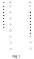
- FIG. 1shows the position of the elements of two classic mono-band arrays which work at frequencies f and f/2 respectively, and the disposition of elements in a multiband interleaved array, which has a dual frequency behaviour (at frequencies f and f/2), working in the same manner as classic arrays but with a smaller total number of elements.
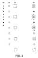
- FIG. 2shows another particular example of multiband interleaved array but with three frequencies in this case, and the respective three classic mono-band arrays which constitute it. It is a matter of extending the case of FIG. 1 to 3 frequencies f, f/2 and f/4.
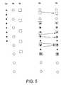
- FIG. 3shows another particular example of multiband interleaved array, in which the different working frequencies are not separated by the same scale factor. It is a matter of extending the case of FIGS. 1 and 2 to 3 frequencies f, f/2 and f/3.
- FIG. 4shows a further particular example of multiband interleaved array, in which the different working frequencies are not separated by the same scale factor. It is a matter of extending the case of FIG. 3 to 3 frequencies f, f/3 and f/4.
- FIG. 5shows a multiband interleaved array configuration which requires a repositioning of the elements to obtain frequencies that do not correspond to an integer factor of the highest frequency.
- the frequencies f, f/2 and f/2,33have been chosen.
- FIG. 6shows the extension of the design of an MIA to the two-dimensional or three-dimensional case, specifically, an extension of the example of FIG. 1 to two dimensions.
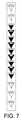
- FIG. 7shows one of the preferred of operating modes (AEM1). It is a matter of an MIA in which the multiband elements are multi-triangular elements.
- the arrayworks simultaneously at dual frequencies, for example in the GSM 900 and GSM 1800 bands.
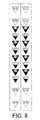
- FIG. 8shows another of the preferred operating modes (AEM2). It is a matter of an MIA in which the multiband elements are multilevel elements.
- the arrayworks simultaneously at dual frequencies, for example in the GSM 900 and GSM 1800 bands.
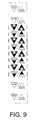
- FIG. 9shows another of the preferred operating modes (AEM3). It is a matter of an MIA in which the multiband elements are multilevel elements. The configuration is similar to that of FIG. 8 (AEM2 mode), the difference being that the new disposition permits the total width of the antenna to be reduced.
- FIG. 10shows another example of multiband antenna which can be employed in MIAs. It is a matter of a stacked patch antenna, which in this specific example works at two dual frequencies (for example, GSM 900 and GSM 1800).
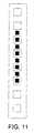
- FIG. 11shows the disposition of said patches in the MIA type array (AEM4 configuration). Observe that, in contrast to the previous cases, in this case multiband antennas are employed only in those positions where it is strictly necessary; in the remainder mono-band elements are employed the radiation pattern of which is sufficiently like that of the multiband element in the pertinent band.
- FIG. 12shows another configuration (AEM5), in which the elements have been rotated through 45° in order to facilitate the procurement of double polarisation at +45° or ⁇ 45°.
- a multiband interleaved arrayis constituted by the juxtaposition of various conventional mono-band arrays.
- the conventional antenna arraysusually have a mono-band behaviour (that is, they work within a relatively small frequency range, typically of the order of 10% about a centre frequency) and this is not only because the elements (antennas) that constitute it have a mono-band behaviour, but also because the physical spacing between elements conditions the working wavelength.
- the conventional mono-band arraysare designed with a spacing between elements of around a half-wavelength, spacing which may be increased in some configurations in order to enhance directivity, though it is usually kept below one wavelength to avoid the appearance of diffraction lobes.
- the multiband interleaved arraysbase their operation on the physical disposition of the antennas which constitute them and on the particular type of element that is employed in some strategic positions of the array.
- the positions of the elements in an MIAare determined from the positions of the elements in as many mono-band arrays as there are frequencies or frequency bands required.
- the design of the arrayis, in that sense, equal to that of the mono-band arrays insomuch as it is possible to choose the current weighting for each element, in order to shape the radiation pattern according to the needs of each application.
- the configuration of the MIAis obtained from the juxtaposition of the positions of the different mono-band arrays. Naturally, such juxtaposition proves difficult to implement in practice in those positions in which various antennas of the different arrays coincide; the solution proposed in this invention rests in the use of a multiband antenna (for example of the fractal, multi-triangular, multi-level, etc. type) which covers all the frequencies associated with its position.
- FIG. 1A basic and particular example of how to arrange the elements in an MIA is described in FIG. 1 .
- the positions of the elementsare chosen in such a manner that the spacing between elements is typically less than the working wavelength.
- the array ( 1 . 2 )would work at a frequency f/2 as the elements have a spacing double that of the previous case.
- the remaining not common elementscan be implemented either by means of the same multiband element employed in the common positions (and selecting the working frequency by means of the signal distribution network of the array), or by employing conventional mono-band elements.
- the array ( 1 . 3 )has a dual behaviour frequency-wise (at frequencies f and f/2), working in the same manner as the arrays ( 1 . 1 ) and ( 1 . 2 ) but with a smaller total number of elements (12 instead of 16).
- multiband antennasare already described in the state of the art.
- Antennas with fractal geometry, multi-triangular antennas, multi-level antennas even stacked patch antennasare some examples of antennas capable of working in like manner in multiple frequency bands.
- These, and other multiband elementscan be employed in the positions of the MIAs in which elements of various mono-band arrays come together.
- FIG. 2the configuration described is that of a tri-band MIA working at frequencies f, f/2 and f/4.
- the disposition of elements in the three classic mono-band arrays at the frequencies f, f/2 and f/4is illustrated in the figures ( 2 . 1 ), ( 2 . 2 ) and ( 2 . 3 ) by means of black circles, circumferences and squares respectively.
- the position of the elements of the MIAis determined from the configuration of the three mono-band arrays designed for each one of the three frequencies. The three arrays come together in the MIA that is shown in figure ( 2 . 4 ).
- FIGS. 3 , 4 and 5describe, by way of example and not restrictively, the design of other MIAs based on the same principle though at other frequencies.
- the frequencies employedare integer multiples of a fundamental frequency; in the case of FIG. 5 the ratio between frequencies is not restricted to any particular rule, though it supposes an example of array in which the frequencies the GSM 900, GSM 1800 and UMTS services can be combined.
- FIG. 3illustrates another particular example of multiband interleaved array, in which the different working frequencies are not separated by the same scale factor. It concerns the extension of the case of FIGS. 1 and 2 to 3 frequencies f, f/2 and f/3.
- the disposition of elements of the three classic mono-band arrays at the frequencies f, f/2 and f/3is shown in figures ( 3 . 1 ), ( 3 . 2 ) and ( 3 . 3 ) by means of black circles, circumferences and squares respectively.
- the column of figure ( 3 . 4 )shows the disposition of elements in the tri-band interleaved array.
- FIG. 4illustrates a new particular example of multiband interleaved array, in which the different working frequencies are not separated by the same scale factor. It concerns the extension of the case of FIG. 3 to 3 frequencies f, f/3 and f/4.
- the disposition of elements of the three classic mono-band arrays at the frequencies f, f/3 and f/4are shown in figures ( 4 . 1 ), ( 4 . 2 ) and ( 4 . 3 ) by means of black circles, circumferences and squares respectively.
- the column of figure ( 4 . 4 )shows the disposition of elements in the tri-band interleaved array.
- the three-frequency array of figure ( 4 . 4 )behaves in the same manner as the three arrays ( 4 . 1 ), ( 4 . 2 ) and ( 4 . 3 ) at their respective working frequencies, but employing only 15 elements instead of the 24 required in the total of the three mono-band arrays.
- the arrayscan work at 3 frequencies simultaneously.
- the disposition of elementsis such that the three frequencies do not always coincide in all the elements; nonetheless, by employing a tri-band antenna in those positions and selecting the working frequencies for example by means of a conventional frequency-selective network, it is possible to implement the MIA.
- the elementsbe repositioned, as in FIG. 5 .
- the frequencies f, f/2 and f/2,33have been chosen.
- the disposition of elements of the three classic mono-band arrays at the frequencies f, f/2 and f/2,33is represented in figures ( 5 . 1 ), ( 5 . 2 ) and ( 5 . 3 ) by means of black circles, circumferences and squares respectively.
- the column of figure ( 5 . 4 )shows what would be the disposition of elements in the tri-band interleaved array according to the same plan as in the previous examples.
- FIG. 6illustrates how the configuration MIAs is not limited to the linear (one-dimensional) case, but it also includes arrays in 2 and 3 dimensions (2D and 3D).
- the procedure for distributing the elements of the array in the 2D and 3D casesis the same, replacing also the different coincident elements with a single multiband antenna.
- the AEM1 configurationis based on the use of GSM 900 and GSM 1800 multi-triangular elements.
- the arrayis obtained by interleaving two conventional mono-band arrays with spacing between elements less than one wavelength ( ) in the pertinent band (typically a spacing is chosen less than 0.9 in order to minimise the appearance of the diffraction lobe in the end-fire direction).
- the original arrayscan have 8 or 10 elements, depending on the gain required by the operator.
- the juxtaposition of both arrays in a single MIAis achieved in this case by employing dual multi-triangular elements.
- Such elementsincorporate two excitation points (one for each band), which allows the working band to be selected according to their position in the array.
- FIG. 7The AEM1 configuration, represented in FIG. 7 , is based on the use of GSM 900 and GSM 1800 multi-triangular elements.
- the arrayis obtained by interleaving two conventional mono-band arrays with spacing between elements less than one wavelength ( ) in the pertinent band (typically
- the position of the elementsis shown, as well as their working frequencies.
- the elements shown in whiteindicate operation in the GSM 900 band; the elements shown in black indicate operation in the GSM 1800 band and the elements marked in black in the lower triangle and in white in their two upper triangles indicate simultaneous operation in both bands.
- the simultaneous operation in both bands via a single multiband element (the multi-triangular element) in such positions of the arrayis one of the main characteristic features of the MIA invention.
- the manner of feeding the elements of the AEM1 arrayis not characteristic of the invention of the MIAs and recourse may be had to any conventionally known system.
- the multi-triangular elementsare excited at two different points, it is possible to make use of an independent distribution network for each band.
- Another alternativeconsists in employing a broadband or dual band distribution network, by coupling a combiner/diplexer which interconnects the network and the two excitation points of the multi-triangular antenna.
- the antennamay therefore come with two input/output connectors (one for each band), or combined in a single connector by means of a combiner/diplexer network.
- This particular configuration of AEM2, shown in FIG. 8is based on a multilevel antenna which acts as a multiband element.
- the antennahas also double linear polarisation at +45° and ⁇ 45° with respect to the longitudinal axis of the array.
- the fact that the antenna has double polarisationsignifies an additional advantage for the cellular telephony operator, since in this manner he can implement a diversity system which minimises the effect of fading by multipath propagation.
- the multilevel element which is described in FIG. 8is more suitable than the multi-triangular element described previously since the element itself has a linear polarisation at +45° in GSM 900 and at ⁇ 45° in GSM 1800.
- the arrayis obtained by interleaving two conventional mono-band arrays with spacing between elements less than one wavelength ( ) in the pertinent band (typically a spacing less than 0.9 is chosen in order to minimise the appearance of the diffraction lobe in the end-fire direction).
- the original arrayscan have 8 or 10 elements depending on the gain required by the operator.
- the juxtaposition of both arrays in a single MIAis achieved in this case by employing in-band dual multilevel elements.
- Such elementsincorporate two points of excitation (one for each band), which permits the working band to be selected according to their position in the array. In FIG. 8 the position of the elements is shown, as well as their working frequencies.
- the elements shown in whiteindicate operation in the GSM 900 band; the elements shown in black indicate operation in the GSM 1800 band and the elements marked in black in their lower triangle and in white in the upper triangles indicate simultaneous operation in both bands. Precisely the simultaneous operation in both bands via a single multiband element (the multilevel element) in such positions of the array (those positions in which those of the original mono-band arrays coincide), is one of the main characteristic features of the MIA invention.
- the manner of feeding the elements of the array AEM2is not characteristic of the invention of the MIAs and recourse can be had to any conventionally known system.
- the multi-triangular elementsare excited at two different points, it is possible to make use of an independent distribution network for each band and polarisation.
- Another alternativeconsists in employing a broadband or dual band distribution network, by coupling a combiner/diplexer which interconnects the network and the two excitation points of the multilevel antenna.
- the antennamay then come with four input/output connectors (one for each band and polarisation), or else combined in only two connectors (one for each independent polarisation) by means of combiner/diplexer network in each polarisation.
- the AEM3 configurationis very similar to the AEM2 (the position of the multilevel elements and the type of element itself is the same as in the previous case), with the difference that the right-hand column is reversed with respect to that on the left.
- the total width of the antennabeing reduced with respect to the previous case (in this particular example the width is reduced by about 10%).
- oblique finsbe inserted between contiguous elements.
- lateral finsare also incorporated in all the elements which work in GSM 1800, fins which contribute to narrowing the radiation beam in the horizontal plane (plane at right angles to the longitudinal axis of the array).
- multiband interleaved arrayis that termed herein AEM4 and which is shown in schematic form in FIG. 11 .
- the multiband elementis a stacked square patch antenna (FIG. 10 ), though it is obvious for anyone familiar with the subject that patches of other shapes could be employed. Square- or circular-shaped types are preferred in the event that is wished to work with double polarisation. In the example of FIG. 10 the particular case is described of square patches.
- the lower patchis of appropriate size for its resonant frequency (associated typically with the patch fundamental mode) to coincide with the lower band (GSM 900 in this specific case); moreover, this patch acts in turn as ground plane of the upper patch.
- the latteris of a size such that its resonance is centered in the upper band (GSM 1800).
- the elements of the arrayare mounted on a metallic or metal-coated surface which acts as ground plane for all the elements of the array.
- the feeder systemis preferentially of the coaxial type, a cable being employed for the lower patch and band and another for the upper patch and band.
- excitation pointsare collated on the bisectors of the patches (for example, the approximate excitation points are marked by means of circles on the plan view of the antenna) if vertical or horizontal polarisation is desired, or on the diagonals if, on the other hand, linear polarisation inclined at 45° is desired.
- each of the patchesis excited additionally on the bisector or diagonal opposite (orthogonal) to the first.
- the feeding of the elements of the array AEM4is not characteristic of the invention of the MIAs and recourse can be had to any conventionally known system.
- the stacked patch antennais excited at two different points, it is possible to make use of an independent distribution network for each band and polarisation.
- Another alternativeconsists in employing a broadband or dual band distribution network, by coupling a combiner/diplexer which interconnects the network and the two excitation points of the multilevel antenna.
- the antennamay then come with four input/output connectors (one for each band and polarisation), or else combined in only two connectors (one for each independent polarisation) by means of a combiner/diplexer network in each polarisation.
- the AEM5 configurationadopts the same approach as the AEM4, though all the elements are rotated through 45° in the plane of the antenna. In this manner the radiation pattern is modified in the horizontal plane, in addition to rotating the polarization through 45°.
- the multiband element constituted by the stacked patchesis really only strictly necessary in those strategic positions in which elements originating in the conventional mono-band arrays coincide. In the remaining positions, it shall be possible to employ indistinctly multiband or mono-band elements that work at the frequency determined for its location, as long as its radiation pattern is sufficiently like that of the stacked patch antenna in order to avoid the appearance of diffraction lobes.
Landscapes
- Engineering & Computer Science (AREA)
- Computer Networks & Wireless Communication (AREA)
- Physics & Mathematics (AREA)
- Electromagnetism (AREA)
- Signal Processing (AREA)
- Variable-Direction Aerials And Aerial Arrays (AREA)
- Waveguide Aerials (AREA)
- Measurement And Recording Of Electrical Phenomena And Electrical Characteristics Of The Living Body (AREA)
Abstract
Description
Claims (19)
Priority Applications (8)
| Application Number | Priority Date | Filing Date | Title |
|---|---|---|---|
| US10/935,559US20050030247A1 (en) | 1999-10-26 | 2004-09-07 | Interlaced multiband antenna arrays |
| US10/988,261US7250918B2 (en) | 1999-10-26 | 2004-11-12 | Interlaced multiband antenna arrays |
| US11/803,782US7557768B2 (en) | 1999-10-26 | 2007-05-16 | Interlaced multiband antenna arrays |
| US12/476,308US7932870B2 (en) | 1999-10-26 | 2009-06-02 | Interlaced multiband antenna arrays |
| US13/044,831US8228256B2 (en) | 1999-10-26 | 2011-03-10 | Interlaced multiband antenna arrays |
| US13/530,249US8896493B2 (en) | 1999-10-26 | 2012-06-22 | Interlaced multiband antenna arrays |
| US14/529,715US9905940B2 (en) | 1999-10-26 | 2014-10-31 | Interlaced multiband antenna arrays |
| US15/875,831US20180145424A1 (en) | 1999-10-26 | 2018-01-19 | Interlaced Multiband Antenna Arrays |
Applications Claiming Priority (1)
| Application Number | Priority Date | Filing Date | Title |
|---|---|---|---|
| PCT/ES1999/000343WO2001031747A1 (en) | 1999-10-26 | 1999-10-26 | Interlaced multiband antenna arrays |
Related Parent Applications (1)
| Application Number | Title | Priority Date | Filing Date |
|---|---|---|---|
| PCT/ES1999/000343ContinuationWO2001031747A1 (en) | 1999-10-26 | 1999-10-26 | Interlaced multiband antenna arrays |
Related Child Applications (2)
| Application Number | Title | Priority Date | Filing Date |
|---|---|---|---|
| US10/935,559ContinuationUS20050030247A1 (en) | 1999-10-26 | 2004-09-07 | Interlaced multiband antenna arrays |
| US10/988,261ContinuationUS7250918B2 (en) | 1999-10-26 | 2004-11-12 | Interlaced multiband antenna arrays |
Publications (2)
| Publication Number | Publication Date |
|---|---|
| US20020171601A1 US20020171601A1 (en) | 2002-11-21 |
| US6937191B2true US6937191B2 (en) | 2005-08-30 |
Family
ID=8307385
Family Applications (9)
| Application Number | Title | Priority Date | Filing Date |
|---|---|---|---|
| US10/135,019Expired - LifetimeUS6937191B2 (en) | 1999-10-26 | 2002-04-23 | Interlaced multiband antenna arrays |
| US10/935,559AbandonedUS20050030247A1 (en) | 1999-10-26 | 2004-09-07 | Interlaced multiband antenna arrays |
| US10/988,261Expired - LifetimeUS7250918B2 (en) | 1999-10-26 | 2004-11-12 | Interlaced multiband antenna arrays |
| US11/803,782Expired - LifetimeUS7557768B2 (en) | 1999-10-26 | 2007-05-16 | Interlaced multiband antenna arrays |
| US12/476,308Expired - Fee RelatedUS7932870B2 (en) | 1999-10-26 | 2009-06-02 | Interlaced multiband antenna arrays |
| US13/044,831Expired - Fee RelatedUS8228256B2 (en) | 1999-10-26 | 2011-03-10 | Interlaced multiband antenna arrays |
| US13/530,249Expired - Fee RelatedUS8896493B2 (en) | 1999-10-26 | 2012-06-22 | Interlaced multiband antenna arrays |
| US14/529,715Expired - LifetimeUS9905940B2 (en) | 1999-10-26 | 2014-10-31 | Interlaced multiband antenna arrays |
| US15/875,831AbandonedUS20180145424A1 (en) | 1999-10-26 | 2018-01-19 | Interlaced Multiband Antenna Arrays |
Family Applications After (8)
| Application Number | Title | Priority Date | Filing Date |
|---|---|---|---|
| US10/935,559AbandonedUS20050030247A1 (en) | 1999-10-26 | 2004-09-07 | Interlaced multiband antenna arrays |
| US10/988,261Expired - LifetimeUS7250918B2 (en) | 1999-10-26 | 2004-11-12 | Interlaced multiband antenna arrays |
| US11/803,782Expired - LifetimeUS7557768B2 (en) | 1999-10-26 | 2007-05-16 | Interlaced multiband antenna arrays |
| US12/476,308Expired - Fee RelatedUS7932870B2 (en) | 1999-10-26 | 2009-06-02 | Interlaced multiband antenna arrays |
| US13/044,831Expired - Fee RelatedUS8228256B2 (en) | 1999-10-26 | 2011-03-10 | Interlaced multiband antenna arrays |
| US13/530,249Expired - Fee RelatedUS8896493B2 (en) | 1999-10-26 | 2012-06-22 | Interlaced multiband antenna arrays |
| US14/529,715Expired - LifetimeUS9905940B2 (en) | 1999-10-26 | 2014-10-31 | Interlaced multiband antenna arrays |
| US15/875,831AbandonedUS20180145424A1 (en) | 1999-10-26 | 2018-01-19 | Interlaced Multiband Antenna Arrays |
Country Status (12)
| Country | Link |
|---|---|
| US (9) | US6937191B2 (en) |
| EP (1) | EP1227545B1 (en) |
| JP (1) | JP2003513496A (en) |
| CN (1) | CN1196231C (en) |
| AT (1) | ATE248443T1 (en) |
| AU (1) | AU1046700A (en) |
| BR (1) | BR9917541A (en) |
| DE (2) | DE69910847D1 (en) |
| DK (1) | DK1227545T3 (en) |
| ES (1) | ES2205898T3 (en) |
| MX (1) | MXPA02004221A (en) |
| WO (1) | WO2001031747A1 (en) |
Cited By (25)
| Publication number | Priority date | Publication date | Assignee | Title |
|---|---|---|---|---|
| US20050146481A1 (en)* | 1999-10-26 | 2005-07-07 | Baliarda Carles P. | Interlaced multiband antenna arrays |
| US20070200718A1 (en)* | 2006-01-10 | 2007-08-30 | Guardian Industries Corp. | Rain sensor with selectively reconfigurable fractal based sensors/capacitors |
| US20080100510A1 (en)* | 2006-10-27 | 2008-05-01 | Bonthron Andrew J | Method and apparatus for microwave and millimeter-wave imaging |
| US7394432B2 (en) | 1999-09-20 | 2008-07-01 | Fractus, S.A. | Multilevel antenna |
| US20090027192A1 (en)* | 2007-07-25 | 2009-01-29 | Tomas Flores | Portable alarm apparatus for warning persons |
| US20090224995A1 (en)* | 2005-10-14 | 2009-09-10 | Carles Puente | Slim triple band antenna array for cellular base stations |
| EP2100783A2 (en) | 2008-03-14 | 2009-09-16 | Guardian Industries Corp. | Rain sensor embedded on printed circuit board |
| EP2100768A2 (en) | 2008-03-14 | 2009-09-16 | Guardian Industries Corp. | Time, space, and/or wavelength multiplexed capacitive light sensor, and related methods |
| EP2100722A2 (en) | 2008-03-14 | 2009-09-16 | Guardian Industries Corp. | Light sensor embedded on printed circuit board |
| US20100171675A1 (en)* | 2007-06-06 | 2010-07-08 | Carmen Borja | Dual-polarized radiating element, dual-band dual-polarized antenna assembly and dual-polarized antenna array |
| US7868843B2 (en) | 2004-08-31 | 2011-01-11 | Fractus, S.A. | Slim multi-band antenna array for cellular base stations |
| US20120280880A1 (en)* | 2011-05-05 | 2012-11-08 | Per-Anders Arvidsson | Antenna array arrangement and a multi band antenna |
| US20130002505A1 (en)* | 2011-06-30 | 2013-01-03 | Anthony Teillet | Forty-five degree dual broad band base station antenna |
| WO2014008173A1 (en) | 2012-07-06 | 2014-01-09 | Guardian Industries Corp. | Moisture sensor and/or defogger with bayesian improvements, and related methods |
| US20140091965A1 (en)* | 2012-09-28 | 2014-04-03 | Battelle Memorial Institute | Apparatus for synthetic imaging of an object |
| US9371032B2 (en) | 2006-01-10 | 2016-06-21 | Guardian Industries Corp. | Moisture sensor and/or defogger with Bayesian improvements, and related methods |
| USD780184S1 (en)* | 2013-03-13 | 2017-02-28 | Nagrastar Llc | Smart card interface |
| USD780763S1 (en)* | 2015-03-20 | 2017-03-07 | Nagrastar Llc | Smart card interface |
| USD792411S1 (en)* | 2013-03-13 | 2017-07-18 | Nagrastar Llc | Smart card interface |
| US10173579B2 (en) | 2006-01-10 | 2019-01-08 | Guardian Glass, LLC | Multi-mode moisture sensor and/or defogger, and related methods |
| USD840404S1 (en) | 2013-03-13 | 2019-02-12 | Nagrastar, Llc | Smart card interface |
| US20190074573A1 (en)* | 2017-09-01 | 2019-03-07 | Phihong Technology Co., Ltd. | Antenna Rotating Head with a Double Grooves Structure |
| US10439267B2 (en) | 2017-03-24 | 2019-10-08 | Samsung Electronics Co., Ltd. | Electronic device including antenna |
| USD864968S1 (en) | 2015-04-30 | 2019-10-29 | Echostar Technologies L.L.C. | Smart card interface |
| US11056773B2 (en)* | 2019-06-28 | 2021-07-06 | Commscope Technologies Llc | Twin-beam base station antennas having thinned arrays with triangular sub-arrays |
Families Citing this family (81)
| Publication number | Priority date | Publication date | Assignee | Title |
|---|---|---|---|---|
| JP4070462B2 (en) | 2000-01-19 | 2008-04-02 | フラクトゥス・ソシエダッド・アノニマ | Small space-filling antenna |
| US6552690B2 (en) | 2001-08-14 | 2003-04-22 | Guardian Industries Corp. | Vehicle windshield with fractal antenna(s) |
| US6956537B2 (en)* | 2001-09-12 | 2005-10-18 | Kathrein-Werke Kg | Co-located antenna array for passive beam forming |
| US9755314B2 (en) | 2001-10-16 | 2017-09-05 | Fractus S.A. | Loaded antenna |
| JP2005533446A (en) | 2002-07-15 | 2005-11-04 | フラクトゥス・ソシエダッド・アノニマ | Undersampled microstrip array using multi-level shaped elements and space-filled shaped elements |
| CN1669182A (en) | 2002-09-10 | 2005-09-14 | 弗拉克托斯股份有限公司 | Coupled Multiband Antennas |
| DE10256960B3 (en) | 2002-12-05 | 2004-07-29 | Kathrein-Werke Kg | Two-dimensional antenna array |
| US7050005B2 (en) | 2002-12-05 | 2006-05-23 | Kathrein-Werke Kg | Two-dimensional antenna array |
| DE10332619B4 (en)* | 2002-12-05 | 2005-07-14 | Kathrein-Werke Kg | Two-dimensional antenna array |
| WO2005076407A2 (en) | 2004-01-30 | 2005-08-18 | Fractus S.A. | Multi-band monopole antennas for mobile communications devices |
| WO2004057701A1 (en) | 2002-12-22 | 2004-07-08 | Fractus S.A. | Multi-band monopole antenna for a mobile communications device |
| FR2860344B1 (en)* | 2003-09-25 | 2005-12-23 | Commissariat Energie Atomique | BROADBAND ANTENNA NETWORK |
| US7064729B2 (en)* | 2003-10-01 | 2006-06-20 | Arc Wireless Solutions, Inc. | Omni-dualband antenna and system |
| US20080111759A1 (en)* | 2004-05-28 | 2008-05-15 | Telefonaktiebolaget Lm Ericksson (Publ) | Antenna Arrangement |
| US7333055B2 (en)* | 2005-03-24 | 2008-02-19 | Agilent Technologies, Inc. | System and method for microwave imaging using an interleaved pattern in a programmable reflector array |
| US20070008236A1 (en)* | 2005-07-06 | 2007-01-11 | Ems Technologies, Inc. | Compact dual-band antenna system |
| CN107425296B (en)* | 2005-07-22 | 2021-05-04 | 英特尔公司 | Antenna device with staggered antenna elements |
| SE529885C2 (en)* | 2006-05-22 | 2007-12-18 | Powerwave Technologies Sweden | Dual band antenna arrangement |
| US8738103B2 (en) | 2006-07-18 | 2014-05-27 | Fractus, S.A. | Multiple-body-configuration multimedia and smartphone multifunction wireless devices |
| DE102007060083A1 (en) | 2007-12-13 | 2009-06-18 | Kathrein-Werke Kg | Multiple gaps-multi bands-antenna-array has two groups provided by emitters or emitter modules, where emitters are formed for transmitting or receiving in common frequency band |
| EP2226890A1 (en)* | 2009-03-03 | 2010-09-08 | Hitachi Cable, Ltd. | Mobile communication base station antenna |
| EP2343777B1 (en)* | 2009-05-26 | 2015-10-07 | Huawei Technologies Co., Ltd. | Antenna device |
| EP2256860B1 (en)* | 2009-05-26 | 2018-12-19 | Alcatel Lucent | Antenna array |
| DE102010028265A1 (en)* | 2010-04-27 | 2011-10-27 | Robert Bosch Gmbh | Antenna device for transmitting and receiving electromagnetic waves |
| US8570237B2 (en) | 2011-02-01 | 2013-10-29 | Raytheon Company | Multi-band electronically scanned array antenna |
| US8674895B2 (en)* | 2011-05-03 | 2014-03-18 | Andrew Llc | Multiband antenna |
| CN102882574B (en)* | 2011-07-15 | 2014-12-31 | 华为技术有限公司 | Antenna system and signal transmitting equipment |
| US9407011B2 (en)* | 2012-02-22 | 2016-08-02 | The United States Of America As Represented By The Secretary Of The Army | Broadband electromagnetic band-gap (EBG) structure |
| CN102916262B (en) | 2011-08-04 | 2015-03-04 | 中国电信股份有限公司 | Multimode antenna and base station |
| US20130132013A1 (en)* | 2011-11-23 | 2013-05-23 | Ge Aviation Systems Llc | Method for diagnosing manufacturing variances |
| US20130132035A1 (en)* | 2011-11-23 | 2013-05-23 | Ge Aviation Systems Llc | Method for diagnosing a health of an apparatus |
| US20130132034A1 (en)* | 2011-11-23 | 2013-05-23 | Ge Aviation Systems Llc | Method for prognosing a health problem of an apparatus |
| US20130132033A1 (en)* | 2011-11-23 | 2013-05-23 | Ge Aviation Systems Llc | System and apparatus for radiation diagnosis |
| US20130154899A1 (en)* | 2011-12-19 | 2013-06-20 | William Lynn Lewis, III | Aperiodic distribution of aperture elements in a dual beam array |
| FR2985099B1 (en)* | 2011-12-23 | 2014-01-17 | Alcatel Lucent | CROSS-POLARIZED MULTIBAND PANEL ANTENNA |
| GB201122324D0 (en) | 2011-12-23 | 2012-02-01 | Univ Edinburgh | Antenna element & antenna device comprising such elements |
| US8847823B2 (en) | 2012-01-09 | 2014-09-30 | Lockheed Martin Corporation | Dimensionally tolerant multiband conformal antenna arrays |
| US10608348B2 (en) | 2012-03-31 | 2020-03-31 | SeeScan, Inc. | Dual antenna systems with variable polarization |
| US9755295B2 (en)* | 2012-05-01 | 2017-09-05 | Avago Technologies General Ip (Singapore) Pte. Ltd. | Antenna configured for use in a wireless transceiver |
| CN103022663A (en)* | 2012-12-05 | 2013-04-03 | 广州中海达卫星导航技术股份有限公司 | Small-sized double-frequency active navigation antenna device |
| KR101494956B1 (en)* | 2013-02-08 | 2015-02-23 | 주식회사 에이스테크놀로지 | Array antenna optimized for a base station communication system |
| EP2959710B1 (en)* | 2013-02-22 | 2019-03-20 | Quintel Cayman Limited | Multi-array antenna |
| US10490908B2 (en) | 2013-03-15 | 2019-11-26 | SeeScan, Inc. | Dual antenna systems with variable polarization |
| JP5965354B2 (en)* | 2013-05-27 | 2016-08-03 | 日本電信電話株式会社 | Antenna and base station apparatus |
| EP2889958B1 (en)* | 2013-12-30 | 2019-01-23 | Alcatel-Lucent Shanghai Bell Co., Ltd. | Multiband antenna |
| ES2848299T3 (en)* | 2014-01-31 | 2021-08-06 | Quintel Cayman Ltd Walkers Corporate Ltd | Antenna system with beamwidth control |
| US20170229785A1 (en)* | 2014-10-10 | 2017-08-10 | Commscope Technologies Llc | Stadium antenna |
| US9893435B2 (en)* | 2015-02-11 | 2018-02-13 | Kymeta Corporation | Combined antenna apertures allowing simultaneous multiple antenna functionality |
| JP6480751B2 (en) | 2015-02-18 | 2019-03-13 | パナソニック株式会社 | Array antenna device |
| US10333215B2 (en)* | 2015-05-14 | 2019-06-25 | Ntt Docomo, Inc. | Multi-band array antenna |
| CN106329151B (en)* | 2015-06-30 | 2019-10-22 | 华为技术有限公司 | A kind of antenna array and network equipment |
| US10418716B2 (en) | 2015-08-27 | 2019-09-17 | Commscope Technologies Llc | Lensed antennas for use in cellular and other communications systems |
| US10109917B2 (en) | 2015-09-30 | 2018-10-23 | Raytheon Company | Cupped antenna |
| US9882282B2 (en) | 2015-10-23 | 2018-01-30 | Apple Inc. | Wireless charging and communications systems with dual-frequency patch antennas |
| US9923284B1 (en)* | 2015-10-28 | 2018-03-20 | National Technology & Engineering Solutions Of Sandia, Llc | Extraordinary electromagnetic transmission by antenna arrays and frequency selective surfaces having compound unit cells with dissimilar elements |
| EP3364500A4 (en)* | 2015-11-23 | 2018-09-05 | Huawei Technologies Co., Ltd. | Antenna unit and antenna array |
| US11303026B2 (en) | 2015-12-09 | 2022-04-12 | Viasat, Inc. | Stacked self-diplexed dual-band patch antenna |
| CN107275808B (en)* | 2016-04-08 | 2021-05-25 | 康普技术有限责任公司 | Ultra-wideband radiators and associated antenna arrays |
| CN106207490B (en)* | 2016-08-18 | 2021-06-25 | 京信通信技术(广州)有限公司 | Multisystem common antenna |
| CN106410396A (en)* | 2016-10-26 | 2017-02-15 | 华南理工大学 | Compact multi-beam antenna array with high and low frequencies of filtering oscillators in interlacing arrangement |
| EP3996205B1 (en)* | 2017-01-24 | 2025-06-25 | Outdoor Wireless Networks LLC | Base station antennas including supplemental arrays |
| US11187795B2 (en)* | 2018-03-19 | 2021-11-30 | Panasonic Intellectual Property Management Co., Ltd. | Radar device |
| US10811787B1 (en)* | 2018-05-03 | 2020-10-20 | Rockwell Collins, Inc. | Systems and methods for wavelength scaled array layout optimization |
| US11682838B2 (en)* | 2018-06-29 | 2023-06-20 | Nokia Shanghai Bell Co., Ltd. | Multiband antenna structure |
| EP3794674A1 (en)* | 2018-06-29 | 2021-03-24 | Nokia Shanghai Bell Co., Ltd. | Multiband antenna structure |
| DE102019125973A1 (en)* | 2018-09-28 | 2020-04-02 | Panasonic Intellectual Property Management Co., Ltd. | Radar device |
| FI128609B (en) | 2018-10-12 | 2020-08-31 | Orbis Systems Oy | Arrangement and method for testing a 4.5g or a 5g base station |
| KR102577295B1 (en)* | 2018-10-23 | 2023-09-12 | 삼성전자주식회사 | Electronic device including antenna formed by overlapping antenna elements transceiving multiple bands of signal |
| EP3667818B1 (en) | 2018-12-12 | 2024-05-08 | Nokia Solutions and Networks Oy | A multi-band antenna and components of multi-band antenna |
| CN109444969A (en)* | 2018-12-29 | 2019-03-08 | 清华大学 | Rays safety detection apparatus and its control method |
| CN215497097U (en)* | 2019-02-01 | 2022-01-11 | 康普技术有限责任公司 | Multiband base station antenna with staggered array |
| CN111525235A (en) | 2019-02-02 | 2020-08-11 | 康普技术有限责任公司 | Multiband Base Station Antenna |
| CN110416721A (en)* | 2019-08-27 | 2019-11-05 | 武汉虹信通信技术有限责任公司 | Radiating element and array antenna |
| JP7362521B2 (en)* | 2020-03-10 | 2023-10-17 | 株式会社東芝 | Radio wave emission source visualization device and band expansion method |
| US11581664B2 (en) | 2020-08-07 | 2023-02-14 | Qualcomm Incorporated | Multiband antennas |
| US12327930B2 (en)* | 2020-09-29 | 2025-06-10 | T-Mobile Usa, Inc. | Multi-band millimeter wave (MMW) antenna arrays |
| WO2022155586A1 (en)* | 2021-01-18 | 2022-07-21 | Galtronics Usa, Inc. | Dual-polarized multi-band base station antenna arrays |
| US11843187B2 (en) | 2021-04-26 | 2023-12-12 | Amazon Technologies, Inc. | Antenna module grounding for phased array antennas |
| KR20230031033A (en)* | 2021-08-26 | 2023-03-07 | 삼성전자주식회사 | Antenna array including a plurality of antennas and arranging method thereof |
| WO2024015749A1 (en)* | 2022-07-11 | 2024-01-18 | Peter Chun Teck Song | Dual mode cloaking base station antenna system using frequency selective surfaces |
| US20240429610A1 (en)* | 2023-06-23 | 2024-12-26 | Qualcomm Incorporated | Patch antenna and dual-band interleaved array with passive element |
Citations (190)
| Publication number | Priority date | Publication date | Assignee | Title |
|---|---|---|---|---|
| US3521284A (en) | 1968-01-12 | 1970-07-21 | John Paul Shelton Jr | Antenna with pattern directivity control |
| US3599214A (en) | 1969-03-10 | 1971-08-10 | New Tronics Corp | Automobile windshield antenna |
| US3622890A (en) | 1968-01-31 | 1971-11-23 | Matsushita Electric Industrial Co Ltd | Folded integrated antenna and amplifier |
| US3683376A (en) | 1970-10-12 | 1972-08-08 | Joseph J O Pronovost | Radar antenna mount |
| US3818490A (en) | 1972-08-04 | 1974-06-18 | Westinghouse Electric Corp | Dual frequency array |
| US3967276A (en) | 1975-01-09 | 1976-06-29 | Beam Guidance Inc. | Antenna structures having reactance at free end |
| US3969730A (en) | 1975-02-12 | 1976-07-13 | The United States Of America As Represented By The Secretary Of Transportation | Cross slot omnidirectional antenna |
| US4024542A (en) | 1974-12-25 | 1977-05-17 | Matsushita Electric Industrial Co., Ltd. | Antenna mount for receiver cabinet |
| US4131893A (en) | 1977-04-01 | 1978-12-26 | Ball Corporation | Microstrip radiator with folded resonant cavity |
| US4141016A (en) | 1977-04-25 | 1979-02-20 | Antenna, Incorporated | AM-FM-CB Disguised antenna system |
| JPS55147806U (en) | 1979-04-07 | 1980-10-24 | ||
| US4471493A (en) | 1982-12-16 | 1984-09-11 | Gte Automatic Electric Inc. | Wireless telephone extension unit with self-contained dipole antenna |
| US4471358A (en) | 1963-04-01 | 1984-09-11 | Raytheon Company | Re-entry chaff dart |
| US4504834A (en) | 1982-12-22 | 1985-03-12 | Motorola, Inc. | Coaxial dipole antenna with extended effective aperture |
| DE3337941A1 (en) | 1983-10-19 | 1985-05-09 | Bayer Ag, 5090 Leverkusen | Passive radar reflectors |
| FR2543744B3 (en) | 1983-04-01 | 1985-08-09 | Icma Spa | ANTENNA FOR AUTO-RADIO |
| US4543581A (en) | 1981-07-10 | 1985-09-24 | Budapesti Radiotechnikai Gyar | Antenna arrangement for personal radio transceivers |
| US4571595A (en) | 1983-12-05 | 1986-02-18 | Motorola, Inc. | Dual band transceiver antenna |
| US4584709A (en) | 1983-07-06 | 1986-04-22 | Motorola, Inc. | Homotropic antenna system for portable radio |
| US4590614A (en) | 1983-01-28 | 1986-05-20 | Robert Bosch Gmbh | Dipole antenna for portable radio |
| US4623894A (en) | 1984-06-22 | 1986-11-18 | Hughes Aircraft Company | Interleaved waveguide and dipole dual band array antenna |
| US4673948A (en) | 1985-12-02 | 1987-06-16 | Gte Government Systems Corporation | Foreshortened dipole antenna with triangular radiators |
| US4730195A (en) | 1985-07-01 | 1988-03-08 | Motorola, Inc. | Shortened wideband decoupled sleeve dipole antenna |
| EP0096847B1 (en) | 1982-06-16 | 1989-02-08 | DIEHL GMBH & CO. | Chaff dispensing device |
| US4839660A (en) | 1983-09-23 | 1989-06-13 | Orion Industries, Inc. | Cellular mobile communication antenna |
| US4843468A (en) | 1986-07-14 | 1989-06-27 | British Broadcasting Corporation | Scanning techniques using hierarchical set of curves |
| US4847629A (en) | 1988-08-03 | 1989-07-11 | Alliance Research Corporation | Retractable cellular antenna |
| US4849766A (en) | 1986-07-04 | 1989-07-18 | Central Glass Company, Limited | Vehicle window glass antenna using transparent conductive film |
| US4857939A (en) | 1988-06-03 | 1989-08-15 | Alliance Research Corporation | Mobile communications antenna |
| GB2215136A (en) | 1988-02-10 | 1989-09-13 | Ronald Cecil Hutchins | Broadsword anti-radar foil |
| US4890114A (en) | 1987-04-30 | 1989-12-26 | Harada Kogyo Kabushiki Kaisha | Antenna for a portable radiotelephone |
| US4894663A (en) | 1987-11-16 | 1990-01-16 | Motorola, Inc. | Ultra thin radio housing with integral antenna |
| US4907011A (en) | 1987-12-14 | 1990-03-06 | Gte Government Systems Corporation | Foreshortened dipole antenna with triangular radiating elements and tapered coaxial feedline |
| US4912481A (en) | 1989-01-03 | 1990-03-27 | Westinghouse Electric Corp. | Compact multi-frequency antenna array |
| EP0297813A3 (en) | 1987-06-27 | 1990-06-20 | Nippon Sheet Glass Co., Ltd. | A vehicle receiving apparatus using a window antenna |
| US4975711A (en) | 1988-08-31 | 1990-12-04 | Samsung Electronic Co., Ltd. | Slot antenna device for portable radiophone |
| US5030963A (en) | 1988-08-22 | 1991-07-09 | Sony Corporation | Signal receiver |
| US5138328A (en) | 1991-08-22 | 1992-08-11 | Motorola, Inc. | Integral diversity antenna for a laptop computer |
| US5168472A (en) | 1991-11-13 | 1992-12-01 | The United States Of America As Represented By The Secretary Of The Navy | Dual-frequency receiving array using randomized element positions |
| US5172084A (en) | 1991-12-18 | 1992-12-15 | Space Systems/Loral, Inc. | Miniature planar filters based on dual mode resonators of circular symmetry |
| US5200756A (en) | 1991-05-03 | 1993-04-06 | Novatel Communications Ltd. | Three dimensional microstrip patch antenna |
| US5214434A (en) | 1992-05-15 | 1993-05-25 | Hsu Wan C | Mobile phone antenna with improved impedance-matching circuit |
| EP0543645A1 (en) | 1991-11-18 | 1993-05-26 | Motorola, Inc. | Embedded antenna for communication devices |
| US5218370A (en) | 1990-12-10 | 1993-06-08 | Blaese Herbert R | Knuckle swivel antenna for portable telephone |
| US5227808A (en) | 1991-05-31 | 1993-07-13 | The United States Of America As Represented By The Secretary Of The Air Force | Wide-band L-band corporate fed antenna for space based radars |
| US5227804A (en) | 1988-07-05 | 1993-07-13 | Nec Corporation | Antenna structure used in portable radio device |
| US5245350A (en) | 1991-07-13 | 1993-09-14 | Nokia Mobile Phones (U.K.) Limited | Retractable antenna assembly with retraction inactivation |
| US5248988A (en) | 1989-12-12 | 1993-09-28 | Nippon Antenna Co., Ltd. | Antenna used for a plurality of frequencies in common |
| US5255002A (en) | 1991-02-22 | 1993-10-19 | Pilkington Plc | Antenna for vehicle window |
| US5257032A (en) | 1991-01-24 | 1993-10-26 | Rdi Electronics, Inc. | Antenna system including spiral antenna and dipole or monopole antenna |
| EP0358090B1 (en) | 1988-09-01 | 1994-08-17 | Asahi Glass Company Ltd. | Window glass for an automobile |
| US5347291A (en) | 1991-12-05 | 1994-09-13 | Moore Richard L | Capacitive-type, electrically short, broadband antenna and coupling systems |
| US5355144A (en) | 1992-03-16 | 1994-10-11 | The Ohio State University | Transparent window antenna |
| US5355318A (en) | 1992-06-02 | 1994-10-11 | Alcatel Alsthom Compagnie Generale D'electricite | Method of manufacturing a fractal object by using steriolithography and a fractal object obtained by performing such a method |
| FR2704359A1 (en) | 1993-04-23 | 1994-10-28 | Hirschmann Richard Gmbh Co | Flat antenna. |
| US5373300A (en) | 1992-05-21 | 1994-12-13 | International Business Machines Corporation | Mobile data terminal with external antenna |
| US5402134A (en) | 1993-03-01 | 1995-03-28 | R. A. Miller Industries, Inc. | Flat plate antenna module |
| WO1995011530A1 (en) | 1992-04-08 | 1995-04-27 | Wipac Group Limited | Vehicle antenna |
| US5420599A (en) | 1993-05-06 | 1995-05-30 | At&T Global Information Solutions Company | Antenna apparatus |
| US5422651A (en) | 1993-10-13 | 1995-06-06 | Chang; Chin-Kang | Pivotal structure for cordless telephone antenna |
| US5451965A (en) | 1992-07-28 | 1995-09-19 | Mitsubishi Denki Kabushiki Kaisha | Flexible antenna for a personal communications device |
| US5451968A (en) | 1992-11-19 | 1995-09-19 | Solar Conversion Corp. | Capacitively coupled high frequency, broad-band antenna |
| US5453751A (en)* | 1991-04-24 | 1995-09-26 | Matsushita Electric Works, Ltd. | Wide-band, dual polarized planar antenna |
| US5471224A (en) | 1993-11-12 | 1995-11-28 | Space Systems/Loral Inc. | Frequency selective surface with repeating pattern of concentric closed conductor paths, and antenna having the surface |
| US5493702A (en) | 1993-04-05 | 1996-02-20 | Crowley; Robert J. | Antenna transmission coupling arrangement |
| US5495261A (en) | 1990-04-02 | 1996-02-27 | Information Station Specialists | Antenna ground system |
| US5534877A (en)* | 1989-12-14 | 1996-07-09 | Comsat | Orthogonally polarized dual-band printed circuit antenna employing radiating elements capacitively coupled to feedlines |
| US5537367A (en) | 1994-10-20 | 1996-07-16 | Lockwood; Geoffrey R. | Sparse array structures |
| WO1996027219A1 (en) | 1995-02-27 | 1996-09-06 | The Chinese University Of Hong Kong | Meandering inverted-f antenna |
| WO1996029755A1 (en) | 1995-03-17 | 1996-09-26 | Elden, Inc. | In-vehicle antenna |
| WO1996038881A1 (en) | 1995-06-02 | 1996-12-05 | Ericsson Inc. | Multiple band printed monopole antenna |
| USH1631H (en) | 1995-10-27 | 1997-02-04 | United States Of America | Method of fabricating radar chaff |
| WO1997006578A1 (en) | 1995-08-09 | 1997-02-20 | Fractal Antenna Systems, Inc. | Fractal antennas, resonators and loading elements |
| WO1997011507A1 (en) | 1995-09-22 | 1997-03-27 | Qualcomm Incorporated | Dual-band octafilar helix antenna |
| US5619205A (en) | 1985-09-25 | 1997-04-08 | The United States Of America As Represented By The Secretary Of The Army | Microarc chaff |
| WO1997032355A1 (en) | 1996-03-01 | 1997-09-04 | Toyota Jidosha Kabushiki Kaisha | Antenna device for vehicles |
| WO1997033338A1 (en) | 1996-03-05 | 1997-09-12 | Research In Motion Limited | Antenna for a radio telecommunications device |
| WO1997035360A1 (en) | 1996-03-22 | 1997-09-25 | Ball Aerospace & Technologies Corp. | Multi-frequency antenna |
| US5684672A (en) | 1996-02-20 | 1997-11-04 | International Business Machines Corporation | Laptop computer with an integrated multi-mode antenna |
| WO1997047054A1 (en) | 1996-06-05 | 1997-12-11 | Intercell Wireless Corporation | Dual resonance antenna for portable telephone |
| US5712640A (en) | 1994-11-28 | 1998-01-27 | Honda Giken Kogyo Kabushiki Kaisha | Radar module for radar system on motor vehicle |
| WO1998012771A1 (en) | 1996-09-18 | 1998-03-26 | Research In Motion Limited | Antenna system for an rf data communications device |
| US5767811A (en) | 1995-09-19 | 1998-06-16 | Murata Manufacturing Co. Ltd. | Chip antenna |
| JPH10209744A (en) | 1997-01-28 | 1998-08-07 | Matsushita Electric Works Ltd | Inverted f-type antenna |
| WO1998036469A1 (en) | 1997-02-18 | 1998-08-20 | Poong Jeong Industrial Co., Ltd. | Antenna device for automotive vehicle |
| US5798688A (en) | 1997-02-07 | 1998-08-25 | Donnelly Corporation | Interior vehicle mirror assembly having communication module |
| ES2112163B1 (en) | 1995-05-19 | 1998-11-16 | Univ Catalunya Politecnica | FRACTAL OR MULTIFRACTAL ANTENNAS. |
| US5841403A (en) | 1995-04-25 | 1998-11-24 | Norand Corporation | Antenna means for hand-held radio devices |
| WO1999003166A1 (en) | 1997-07-09 | 1999-01-21 | Allgon Ab | Antenna device for a hand-portable radio communication unit |
| WO1999003167A1 (en) | 1997-07-09 | 1999-01-21 | Allgon Ab | Hand-portable telephone with radiation absorbing device |
| US5870066A (en) | 1995-12-06 | 1999-02-09 | Murana Mfg. Co. Ltd. | Chip antenna having multiple resonance frequencies |
| US5872546A (en) | 1995-09-27 | 1999-02-16 | Ntt Mobile Communications Network Inc. | Broadband antenna using a semicircular radiator |
| US5898404A (en) | 1995-12-22 | 1999-04-27 | Industrial Technology Research Institute | Non-coplanar resonant element printed circuit board antenna |
| US5903240A (en) | 1996-02-13 | 1999-05-11 | Murata Mfg. Co. Ltd | Surface mounting antenna and communication apparatus using the same antenna |
| WO1999025042A1 (en) | 1997-11-06 | 1999-05-20 | Telefonaktiebolaget Lm Ericsson | A portable electronic communication device with multi-band antenna system |
| EP0871238A3 (en) | 1997-03-25 | 1999-05-26 | Nokia Mobile Phones Ltd. | Broadband antenna realized with shorted microstrips |
| WO1999027608A1 (en) | 1997-11-22 | 1999-06-03 | Nathan Cohen | Cylindrical conformable antenna on a planar substrate |
| US5926141A (en) | 1996-08-16 | 1999-07-20 | Fuba Automotive Gmbh | Windowpane antenna with transparent conductive layer |
| US5943020A (en) | 1996-03-13 | 1999-08-24 | Ascom Tech Ag | Flat three-dimensional antenna |
| EP0814536A3 (en) | 1996-06-20 | 1999-10-13 | Kabushiki Kaisha Yokowo | Antenna and radio apparatus using same |
| US5973651A (en) | 1996-09-20 | 1999-10-26 | Murata Manufacturing Co., Ltd. | Chip antenna and antenna device |
| WO1999056345A1 (en) | 1998-04-24 | 1999-11-04 | Intenna Technology Ab | Multiple band antenna device |
| US5986610A (en) | 1995-10-11 | 1999-11-16 | Miron; Douglas B. | Volume-loaded short dipole antenna |
| US5990838A (en) | 1996-06-12 | 1999-11-23 | 3Com Corporation | Dual orthogonal monopole antenna system |
| WO1999062139A1 (en) | 1998-05-27 | 1999-12-02 | Kathrein Werke Kg | Dual polarised multi-range antenna |
| US6002367A (en) | 1996-05-17 | 1999-12-14 | Allgon Ab | Planar antenna device |
| WO2000001028A1 (en) | 1998-06-26 | 2000-01-06 | Research In Motion Limited | Dual embedded antenna for an rf data communications device |
| WO2000003453A1 (en) | 1998-07-09 | 2000-01-20 | Telefonaktiebolaget Lm Ericsson (Publ) | Miniature printed spiral antenna for mobile terminals |
| US6028568A (en) | 1997-12-11 | 2000-02-22 | Murata Manufacturing Co., Ltd. | Chip-antenna |
| US6031499A (en) | 1998-05-22 | 2000-02-29 | Intel Corporation | Multi-purpose vehicle antenna |
| WO2000022695A1 (en) | 1998-10-12 | 2000-04-20 | Amphenol Socapex | Patch antenna |
| US6078294A (en) | 1996-03-01 | 2000-06-20 | Toyota Jidosha Kabushiki Kaisha | Antenna device for vehicles |
| WO2000036700A1 (en) | 1998-12-16 | 2000-06-22 | Telefonaktiebolaget Lm Ericsson (Publ) | Printed multi-band patch antenna |
| US6091365A (en)* | 1997-02-24 | 2000-07-18 | Telefonaktiebolaget Lm Ericsson | Antenna arrangements having radiating elements radiating at different frequencies |
| EP1018777A3 (en) | 1998-12-22 | 2000-07-19 | Nokia Mobile Phones Ltd. | Dual band antenna for a hand portable telephone and a corresponding hand portable telephone |
| US6097345A (en) | 1998-11-03 | 2000-08-01 | The Ohio State University | Dual band antenna for vehicles |
| US6104349A (en) | 1995-08-09 | 2000-08-15 | Cohen; Nathan | Tuning fractal antennas and fractal resonators |
| WO2000049680A1 (en) | 1999-02-16 | 2000-08-24 | Gentex Corporation | Rearview mirror with integrated microwave receiver |
| WO2000052787A1 (en) | 1999-03-02 | 2000-09-08 | Nederlandse Organisatie Voor Toegepast-Natuurwetenschappelijk Onderzoek Tno | Volumetric phased array antenna system |
| WO2000052784A1 (en) | 1999-03-01 | 2000-09-08 | Siemens Aktiengesellschaft | Integrable multiband antenna |
| US6127977A (en) | 1996-11-08 | 2000-10-03 | Cohen; Nathan | Microstrip patch antenna with fractal structure |
| US6131042A (en) | 1998-05-04 | 2000-10-10 | Lee; Chang | Combination cellular telephone radio receiver and recorder mechanism for vehicles |
| US6140969A (en) | 1996-10-16 | 2000-10-31 | Fuba Automotive Gmbh & Co. Kg | Radio antenna arrangement with a patch antenna |
| ES2142280B1 (en) | 1998-05-06 | 2000-11-16 | Univ Catalunya Politecnica | DUAL MULTITRIANGULAR ANTENNAS FOR CELL PHONE GSM AND DCS |
| US6160513A (en) | 1997-12-22 | 2000-12-12 | Nokia Mobile Phones Limited | Antenna |
| US6172618B1 (en) | 1998-12-07 | 2001-01-09 | Mitsubushi Denki Kabushiki Kaisha | ETC car-mounted equipment |
| WO2001003238A1 (en) | 1999-06-29 | 2001-01-11 | Siemens Aktiengesellschaft | Integrable dual-band antenna |
| WO2001008257A1 (en) | 1999-07-23 | 2001-02-01 | Avantego Ab | Antenna arrangement |
| WO2001013464A1 (en) | 1999-08-18 | 2001-02-22 | Ericsson, Inc. | A dual band bowtie/meander antenna |
| EP0932219A3 (en) | 1998-01-21 | 2001-03-07 | Filtronic LK Oy | Planar antenna |
| WO2001017064A1 (en) | 1999-08-27 | 2001-03-08 | Antennas America, Inc. | Compact planar inverted f antenna |
| WO2001022528A1 (en) | 1999-09-20 | 2001-03-29 | Fractus, S.A. | Multilevel antennae |
| US6211824B1 (en)* | 1999-05-06 | 2001-04-03 | Raytheon Company | Microstrip patch antenna |
| WO2001024314A1 (en) | 1999-09-30 | 2001-04-05 | Harada Industries (Europe) Limited | Dual-band microstrip antenna |
| WO2001026182A1 (en) | 1999-10-04 | 2001-04-12 | Smarteq Wireless Ab | Antenna means |
| US6218992B1 (en) | 2000-02-24 | 2001-04-17 | Ericsson Inc. | Compact, broadband inverted-F antennas with conductive elements and wireless communicators incorporating same |
| WO2001028035A1 (en) | 1999-10-12 | 2001-04-19 | Arc Wireless Solutions, Inc. | Compact dual narrow band microstrip antenna |
| WO2001031739A1 (en) | 1999-10-08 | 2001-05-03 | Antennas America, Inc. | Compact microstrip antenna for gps applications |
| WO2001033665A1 (en) | 1999-11-04 | 2001-05-10 | Rangestar Wireless, Inc. | Single or dual band parasitic antenna assembly |
| WO2001035491A1 (en) | 1999-11-12 | 2001-05-17 | France Telecom | Dual-frequency band printed antenna |
| US6236372B1 (en) | 1997-03-22 | 2001-05-22 | Fuba Automotive Gmbh | Antenna for radio and television reception in motor vehicles |
| WO2001037369A1 (en) | 1999-11-19 | 2001-05-25 | Allgon Ab | An antenna device and a communication device comprising such an antenna device |
| WO2001037370A1 (en) | 1999-11-17 | 2001-05-25 | Allgon Ab | An antenna device, a communication device comprising such an antenna device and a method of operating the communication device |
| WO2001041252A1 (en) | 1999-12-02 | 2001-06-07 | Siemens Aktiengesellschaft | Mobile communications terminal |
| EP1094545A3 (en) | 1999-10-20 | 2001-07-04 | Filtronic LK Oy | Internal antenna for an apparatus |
| WO2001048861A1 (en) | 1999-12-23 | 2001-07-05 | Allgon Ab | A method and a blank for use in the manufacturing of an antenna device |
| US6266023B1 (en) | 1999-06-24 | 2001-07-24 | Delphi Technologies, Inc. | Automotive radio frequency antenna system |
| WO2001054225A1 (en) | 2000-01-19 | 2001-07-26 | Fractus, S.A. | Space-filling miniature antennas |
| WO2001073890A1 (en) | 2000-03-28 | 2001-10-04 | Gentex Corporation | Microwave antenna for use in a vehicle |
| WO2001082410A1 (en) | 2000-04-19 | 2001-11-01 | Advanced Automotive Antennas, S.L. | Multilevel advanced antenna for motor vehicles |
| EP0688040B1 (en) | 1994-06-13 | 2001-12-05 | Nippon Telegraph And Telephone Corporation | Bidirectional printed antenna |
| US6329954B1 (en) | 2000-04-14 | 2001-12-11 | Receptec L.L.C. | Dual-antenna system for single-frequency band |
| US6329951B1 (en) | 2000-04-05 | 2001-12-11 | Research In Motion Limited | Electrically connected multi-feed antenna system |
| US20020000942A1 (en) | 1998-09-23 | 2002-01-03 | Bernard Duroux | Vehicle exterior mirror with antenna |
| US20020000940A1 (en) | 1998-06-24 | 2002-01-03 | Stefan Moren | An antenna device, a method for manufacturing an antenna device and a radio communication device including an antenna device |
| EP0997974B1 (en) | 1998-10-30 | 2002-01-09 | Filtronic LK Oy | Planar antenna with two resonating frequencies |
| US20020036594A1 (en) | 2000-01-10 | 2002-03-28 | Gyenes Charles M. | Frequency adjustable mobile antenna and method of making |
| US6367939B1 (en) | 2001-01-25 | 2002-04-09 | Gentex Corporation | Rearview mirror adapted for communication devices |
| EP1198027A1 (en) | 2000-10-12 | 2002-04-17 | The Furukawa Electric Co., Ltd. | Small antenna |
| WO2002035646A1 (en) | 2000-10-26 | 2002-05-02 | Advanced Automotive Antennas, S.L. | Integrated multiservice car antenna |
| US6407710B2 (en) | 2000-04-14 | 2002-06-18 | Tyco Electronics Logistics Ag | Compact dual frequency antenna with multiple polarization |
| US6417810B1 (en) | 1999-06-02 | 2002-07-09 | Daimlerchrysler Ag | Antenna arrangement in motor vehicles |
| US20020105468A1 (en) | 2000-05-15 | 2002-08-08 | Virginie Tessier | Antenna for vehicle |
| US6431712B1 (en) | 2001-07-27 | 2002-08-13 | Gentex Corporation | Automotive rearview mirror assembly including a helical antenna with a non-circular cross-section |
| US20020109633A1 (en) | 2001-02-14 | 2002-08-15 | Steven Ow | Low cost microstrip antenna |
| EP1237224A1 (en) | 2001-02-14 | 2002-09-04 | Siemens Aktiengesellschaft | Antenna and method for fabricating same |
| US20020126054A1 (en) | 2000-10-20 | 2002-09-12 | Peter Fuerst | Exterior mirror with antenna |
| US20020126055A1 (en) | 2001-01-10 | 2002-09-12 | Fuba Automotive Gmbh & Co. Kg | Diversity antenna on a dielectric surface in a motor vehicle body |
| US6452553B1 (en) | 1995-08-09 | 2002-09-17 | Fractal Antenna Systems, Inc. | Fractal antennas and fractal resonators |
| US6452549B1 (en) | 2000-05-02 | 2002-09-17 | Bae Systems Information And Electronic Systems Integration Inc | Stacked, multi-band look-through antenna |
| GB2330951B (en) | 1997-11-04 | 2002-09-18 | Nokia Mobile Phones Ltd | Antenna |
| US6476766B1 (en) | 1997-11-07 | 2002-11-05 | Nathan Cohen | Fractal antenna ground counterpoise, ground planes, and loading elements and microstrip patch antennas with fractal structure |
| WO2002091518A1 (en) | 2001-05-04 | 2002-11-14 | Harris Corporation | Spatially orthogonal signal distribution and support architecture for multi-beam phased array antenna |
| US20020175866A1 (en) | 2001-05-25 | 2002-11-28 | Gram Hans Erik | Antenna |
| WO2002096166A9 (en) | 2001-05-18 | 2003-01-30 | Corp For Nat Res Initiatives | Radio frequency microelectromechanical systems (mems) devices on low-temperature co-fired ceramic (ltcc) substrates |
| US6525691B2 (en)* | 2000-06-28 | 2003-02-25 | The Penn State Research Foundation | Miniaturized conformal wideband fractal antennas on high dielectric substrates and chiral layers |
| EP1083624A3 (en) | 1999-09-10 | 2003-04-02 | Filtronic LK Oy | Planar antenna structure |
| US6552690B2 (en) | 2001-08-14 | 2003-04-22 | Guardian Industries Corp. | Vehicle windshield with fractal antenna(s) |
| EP1079462A3 (en) | 1999-08-25 | 2003-05-02 | Filtronic LK Oy | Planar antenna structure |
| EP0929121B1 (en) | 1998-01-09 | 2003-07-23 | Nokia Corporation | Antenna for mobile communcations device |
| GB2355116B (en) | 1999-10-08 | 2003-10-08 | Nokia Mobile Phones Ltd | An antenna assembly and method of construction |
| EP1071161B1 (en) | 1999-07-19 | 2003-10-08 | Raytheon Company | Multiple stacked patch antenna |
| EP0969375A3 (en) | 1998-06-30 | 2003-11-12 | Sun Microsystems, Inc. | Method for visualizing locality within an address space |
| EP1267438A4 (en) | 2000-03-15 | 2004-03-31 | Matsushita Electric Industrial Co Ltd | MULTI-LAYER ELECTRONIC COMPONENT, MULTI-LAYER ANTENNA DUPLEXER, AND COMMUNICATION APPARATUS |
| EP1018779B1 (en) | 1999-01-05 | 2004-06-30 | Filtronic LK Oy | Planar dual-frequency antenna and radio apparatus employing a planar antenna |
| EP0986130B1 (en) | 1998-09-08 | 2004-08-04 | Siemens Aktiengesellschaft | Antenna for wireless communication terminal device |
| EP0942488B1 (en) | 1998-02-24 | 2004-09-15 | Murata Manufacturing Co., Ltd. | Antenna device and radio device comprising the same |
| EP1148581B1 (en) | 2000-04-17 | 2004-12-08 | Kosan I & T Co., Ltd. | Microstrip antenna |
| EP0892459B1 (en) | 1997-07-08 | 2004-12-15 | Nokia Corporation | Double resonance antenna structure for several frequency ranges |
| EP1096602B1 (en) | 1999-11-01 | 2005-02-09 | Filtronic LK Oy | Planar antenna |
Family Cites Families (71)
| Publication number | Priority date | Publication date | Assignee | Title |
|---|---|---|---|---|
| US940A (en)* | 1838-09-22 | Machine eor hulling rice | ||
| US126053A (en)* | 1872-04-23 | Improvement in paper-files | ||
| US105468A (en)* | 1870-07-19 | Alexis maraisj of st | ||
| US126054A (en)* | 1872-04-23 | Improvement in pedestals for street-railway cars | ||
| US175866A (en)* | 1876-04-11 | Improvement in fog-signals | ||
| US36594A (en)* | 1862-09-30 | Improvement in apparatus for piercing cloth for button-holes | ||
| US942A (en)* | 1838-09-22 | Improved gas-meter | ||
| US3482248A (en) | 1967-07-31 | 1969-12-02 | Us Army | Multifrequency common aperture manifold antenna |
| US3939730A (en)* | 1974-10-08 | 1976-02-24 | Dehaan Robert D | Housing for motorcycle drive chain |
| GB2006635A (en) | 1977-10-27 | 1979-05-10 | Knecht Filterwerke Gmbh | Air Filter for Engines |
| US4243990A (en)* | 1979-04-30 | 1981-01-06 | International Telephone And Telegraph Corporation | Integrated multiband array antenna |
| JPS55147806A (en) | 1979-05-07 | 1980-11-18 | Matsushita Electric Ind Co Ltd | Rod antenna |
| GB2112579A (en) | 1981-09-10 | 1983-07-20 | Nat Res Dev | Multiband dipoles and ground plane antennas |
| CA1244978A (en) | 1985-04-25 | 1988-11-15 | Francisco A. Middleton | Single line telephone communication system |
| US4675687A (en) | 1986-01-22 | 1987-06-23 | General Motors Corporation | AM-FM cellular telephone multiband antenna for motor vehicle |
| JPH057109Y2 (en) | 1986-08-13 | 1993-02-23 | ||
| FR2640431B1 (en)* | 1988-12-08 | 1991-05-10 | Alcatel Espace | MULTI-FREQUENCY RADIANT DEVICE |
| US5231407A (en) | 1989-04-18 | 1993-07-27 | Novatel Communications, Ltd. | Duplexing antenna for portable radio transceiver |
| US5001493A (en) | 1989-05-16 | 1991-03-19 | Hughes Aircraft Company | Multiband gridded focal plane array antenna |
| US5347287A (en)* | 1991-04-19 | 1994-09-13 | Hughes Missile Systems Company | Conformal phased array antenna |
| WO1992019021A1 (en) | 1991-04-22 | 1992-10-29 | The Commonwealth Of Australia | Implementation of multiple apertures through antenna interleaving and splitting |
| JP2653277B2 (en) | 1991-06-27 | 1997-09-17 | 三菱電機株式会社 | Portable wireless communication device |
| JP2751683B2 (en) | 1991-09-11 | 1998-05-18 | 三菱電機株式会社 | Multi-layer array antenna device |
| US5216370A (en)* | 1991-10-24 | 1993-06-01 | Corrpro Companies, Inc. | Method and system for measuring the polarized potential of a cathodically protected structures substantially IR drop free |
| JP3168219B2 (en) | 1991-10-31 | 2001-05-21 | 原田工業株式会社 | Ultra high frequency antenna for wireless telephone |
| US5307075A (en)* | 1991-12-12 | 1994-04-26 | Allen Telecom Group, Inc. | Directional microstrip antenna with stacked planar elements |
| JP2558571B2 (en) | 1992-03-23 | 1996-11-27 | 株式会社ヨコオ | Rod antenna |
| US5307078A (en)* | 1992-03-26 | 1994-04-26 | Harada Kogyo Kabushiki Kaisha | AM-FM-cellular mobile telephone tri-band antenna with double sleeves |
| JPH05347507A (en) | 1992-06-12 | 1993-12-27 | Junkosha Co Ltd | Antenna |
| JPH06204908A (en) | 1993-01-07 | 1994-07-22 | Nippon Motorola Ltd | Radio antenna |
| FR2706085B1 (en)* | 1993-06-03 | 1995-07-07 | Alcatel Espace | Multilayer radiating structure with variable directivity. |
| US6151310A (en) | 1994-03-24 | 2000-11-21 | Ericsson Inc. | Dividable transmit antenna array for a cellular base station and associated method |
| US5724666A (en) | 1994-03-24 | 1998-03-03 | Ericsson Inc. | Polarization diversity phased array cellular base station and associated methods |
| US5451966A (en) | 1994-09-23 | 1995-09-19 | The Antenna Company | Ultra-high frequency, slot coupled, low-cost antenna system |
| US5557291A (en) | 1995-05-25 | 1996-09-17 | Hughes Aircraft Company | Multiband, phased-array antenna with interleaved tapered-element and waveguide radiators |
| US7019695B2 (en) | 1997-11-07 | 2006-03-28 | Nathan Cohen | Fractal antenna ground counterpoise, ground planes, and loading elements and microstrip patch antennas with fractal structure |
| JP3243595B2 (en) | 1995-10-31 | 2002-01-07 | 株式会社トーキン | Multi-band antenna and multi-band portable radio using the same |
| US5726662A (en) | 1995-11-29 | 1998-03-10 | Northrop Grumman Corporation | Frequency compensated multi-beam antenna and method therefor |
| US6006075A (en) | 1996-06-18 | 1999-12-21 | Telefonaktiebolaget L M Ericsson (Publ) | Method and apparatus for transmitting communication signals using transmission space diversity and frequency diversity |
| DE19627015C2 (en) | 1996-07-04 | 2000-07-13 | Kathrein Werke Kg | Antenna field |
| DE19632282A1 (en) | 1996-08-09 | 1998-02-19 | Holzer Walter Prof Dr H C Ing | Process and device for controlling the brightness of fluorescent lamps |
| US5969689A (en) | 1997-01-13 | 1999-10-19 | Metawave Communications Corporation | Multi-sector pivotal antenna system and method |
| JP3063826B2 (en) | 1997-01-17 | 2000-07-12 | 日本電気株式会社 | Multi-frequency antenna |
| SE510995C2 (en)* | 1997-03-24 | 1999-07-19 | Ericsson Telefon Ab L M | Active broadcast / receive group antenna |
| DE69836530T2 (en) | 1997-06-02 | 2007-06-06 | Ntt Mobile Communications Network Inc. | ADAPTIVE GROUP ANTENNA |
| SE511064C2 (en) | 1997-12-12 | 1999-07-26 | Allgon Ab | dual band antenna |
| CA2225677A1 (en) | 1997-12-22 | 1999-06-22 | Philippe Lafleur | Multiple parasitic coupling to an outer antenna patch element from inner path elements |
| US6072439A (en)* | 1998-01-15 | 2000-06-06 | Andrew Corporation | Base station antenna for dual polarization |
| JP3233088B2 (en) | 1998-01-22 | 2001-11-26 | 松下電器産業株式会社 | Directivity control antenna device |
| WO1999059223A2 (en) | 1998-05-11 | 1999-11-18 | Csa Limited | Dual-band microstrip antenna array |
| SE512439C2 (en)* | 1998-06-26 | 2000-03-20 | Allgon Ab | Dual band antenna |
| US6154180A (en) | 1998-09-03 | 2000-11-28 | Padrick; David E. | Multiband antennas |
| US6054953A (en)* | 1998-12-10 | 2000-04-25 | Allgon Ab | Dual band antenna |
| US6239765B1 (en)* | 1999-02-27 | 2001-05-29 | Rangestar Wireless, Inc. | Asymmetric dipole antenna assembly |
| SE515092C2 (en) | 1999-03-15 | 2001-06-11 | Allgon Ab | Double band antenna device |
| US6175333B1 (en)* | 1999-06-24 | 2001-01-16 | Nortel Networks Corporation | Dual band antenna |
| DK1227545T3 (en)* | 1999-10-26 | 2003-10-27 | Fractus Sa | Interlaced multi-band antenna arrangements |
| US6307519B1 (en) | 1999-12-23 | 2001-10-23 | Hughes Electronics Corporation | Multiband antenna system using RF micro-electro-mechanical switches, method for transmitting multiband signals, and signal produced therefrom |
| US6211841B1 (en)* | 1999-12-28 | 2001-04-03 | Nortel Networks Limited | Multi-band cellular basestation antenna |
| DE10012809A1 (en)* | 2000-03-16 | 2001-09-27 | Kathrein Werke Kg | Dual polarized dipole array antenna has supply cable fed to supply point on one of two opposing parallel dipoles, connecting cable to supply point on opposing dipole |
| DE10064129B4 (en)* | 2000-12-21 | 2006-04-20 | Kathrein-Werke Kg | Antenna, in particular mobile radio antenna |
| MXPA03009485A (en) | 2001-04-16 | 2004-05-05 | Fractus Sa | Dual-band dual-polarized antenna array. |
| US6552687B1 (en)* | 2002-01-17 | 2003-04-22 | Harris Corporation | Enhanced bandwidth single layer current sheet antenna |
| US6795020B2 (en)* | 2002-01-24 | 2004-09-21 | Ball Aerospace And Technologies Corp. | Dual band coplanar microstrip interlaced array |
| FI113280B (en)* | 2002-04-03 | 2004-03-31 | Outokumpu Oy | Useful displacement and insulation device for electrolysis |
| DE10256960B3 (en)* | 2002-12-05 | 2004-07-29 | Kathrein-Werke Kg | Two-dimensional antenna array |
| WO2004055938A2 (en) | 2002-12-13 | 2004-07-01 | Andrew Corporation | Improvements relating to dipole antennas and coaxial to microstrip transitions |
| US7250916B2 (en)* | 2005-07-19 | 2007-07-31 | Novatel Inc. | Leaky wave antenna with radiating structure including fractal loops |
| JP5129816B2 (en) | 2006-07-31 | 2013-01-30 | ティー.エー.ジー. メディカル デヴァイシス−アグリカルチャー コーポラティヴ リミテッド | Arthroscopic bone grafting and medical devices useful for it |
| JP5267916B2 (en) | 2008-06-30 | 2013-08-21 | 株式会社リコー | Image forming apparatus and image density control method |
| US9320781B2 (en) | 2011-05-16 | 2016-04-26 | Vital Foods Limited | Dietary supplement for managing gut health |
- 1999
- 1999-10-26DKDK99953985Tpatent/DK1227545T3/enactive
- 1999-10-26MXMXPA02004221Apatent/MXPA02004221A/ennot_activeIP Right Cessation
- 1999-10-26BRBR9917541-0Apatent/BR9917541A/ennot_activeIP Right Cessation
- 1999-10-26JPJP2001533596Apatent/JP2003513496A/enactivePending
- 1999-10-26CNCNB998170224Apatent/CN1196231C/ennot_activeCeased
- 1999-10-26DEDE69910847Apatent/DE69910847D1/ennot_activeExpired - Lifetime
- 1999-10-26EPEP99953985Apatent/EP1227545B1/ennot_activeRevoked
- 1999-10-26DEDE69910847Tpatent/DE69910847T4/ennot_activeExpired - Lifetime
- 1999-10-26ESES99953985Tpatent/ES2205898T3/ennot_activeExpired - Lifetime
- 1999-10-26AUAU10467/00Apatent/AU1046700A/ennot_activeAbandoned
- 1999-10-26ATAT99953985Tpatent/ATE248443T1/ennot_activeIP Right Cessation
- 1999-10-26WOPCT/ES1999/000343patent/WO2001031747A1/enactiveApplication Filing
- 2002
- 2002-04-23USUS10/135,019patent/US6937191B2/ennot_activeExpired - Lifetime
- 2004
- 2004-09-07USUS10/935,559patent/US20050030247A1/ennot_activeAbandoned
- 2004-11-12USUS10/988,261patent/US7250918B2/ennot_activeExpired - Lifetime
- 2007
- 2007-05-16USUS11/803,782patent/US7557768B2/ennot_activeExpired - Lifetime
- 2009
- 2009-06-02USUS12/476,308patent/US7932870B2/ennot_activeExpired - Fee Related
- 2011
- 2011-03-10USUS13/044,831patent/US8228256B2/ennot_activeExpired - Fee Related
- 2012
- 2012-06-22USUS13/530,249patent/US8896493B2/ennot_activeExpired - Fee Related
- 2014
- 2014-10-31USUS14/529,715patent/US9905940B2/ennot_activeExpired - Lifetime
- 2018
- 2018-01-19USUS15/875,831patent/US20180145424A1/ennot_activeAbandoned
Patent Citations (202)
| Publication number | Priority date | Publication date | Assignee | Title |
|---|---|---|---|---|
| US4471358A (en) | 1963-04-01 | 1984-09-11 | Raytheon Company | Re-entry chaff dart |
| US3521284A (en) | 1968-01-12 | 1970-07-21 | John Paul Shelton Jr | Antenna with pattern directivity control |
| US3622890A (en) | 1968-01-31 | 1971-11-23 | Matsushita Electric Industrial Co Ltd | Folded integrated antenna and amplifier |
| US3599214A (en) | 1969-03-10 | 1971-08-10 | New Tronics Corp | Automobile windshield antenna |
| US3683376A (en) | 1970-10-12 | 1972-08-08 | Joseph J O Pronovost | Radar antenna mount |
| US3818490A (en) | 1972-08-04 | 1974-06-18 | Westinghouse Electric Corp | Dual frequency array |
| US4024542A (en) | 1974-12-25 | 1977-05-17 | Matsushita Electric Industrial Co., Ltd. | Antenna mount for receiver cabinet |
| US3967276A (en) | 1975-01-09 | 1976-06-29 | Beam Guidance Inc. | Antenna structures having reactance at free end |
| US3969730A (en) | 1975-02-12 | 1976-07-13 | The United States Of America As Represented By The Secretary Of Transportation | Cross slot omnidirectional antenna |
| US4131893A (en) | 1977-04-01 | 1978-12-26 | Ball Corporation | Microstrip radiator with folded resonant cavity |
| US4141016A (en) | 1977-04-25 | 1979-02-20 | Antenna, Incorporated | AM-FM-CB Disguised antenna system |
| JPS55147806U (en) | 1979-04-07 | 1980-10-24 | ||
| US4543581A (en) | 1981-07-10 | 1985-09-24 | Budapesti Radiotechnikai Gyar | Antenna arrangement for personal radio transceivers |
| EP0096847B1 (en) | 1982-06-16 | 1989-02-08 | DIEHL GMBH & CO. | Chaff dispensing device |
| US4471493A (en) | 1982-12-16 | 1984-09-11 | Gte Automatic Electric Inc. | Wireless telephone extension unit with self-contained dipole antenna |
| US4504834A (en) | 1982-12-22 | 1985-03-12 | Motorola, Inc. | Coaxial dipole antenna with extended effective aperture |
| US4590614A (en) | 1983-01-28 | 1986-05-20 | Robert Bosch Gmbh | Dipole antenna for portable radio |
| FR2543744B3 (en) | 1983-04-01 | 1985-08-09 | Icma Spa | ANTENNA FOR AUTO-RADIO |
| US4584709A (en) | 1983-07-06 | 1986-04-22 | Motorola, Inc. | Homotropic antenna system for portable radio |
| US4839660A (en) | 1983-09-23 | 1989-06-13 | Orion Industries, Inc. | Cellular mobile communication antenna |
| DE3337941A1 (en) | 1983-10-19 | 1985-05-09 | Bayer Ag, 5090 Leverkusen | Passive radar reflectors |
| US4571595A (en) | 1983-12-05 | 1986-02-18 | Motorola, Inc. | Dual band transceiver antenna |
| US4623894A (en) | 1984-06-22 | 1986-11-18 | Hughes Aircraft Company | Interleaved waveguide and dipole dual band array antenna |
| US4730195A (en) | 1985-07-01 | 1988-03-08 | Motorola, Inc. | Shortened wideband decoupled sleeve dipole antenna |
| US5619205A (en) | 1985-09-25 | 1997-04-08 | The United States Of America As Represented By The Secretary Of The Army | Microarc chaff |
| US4673948A (en) | 1985-12-02 | 1987-06-16 | Gte Government Systems Corporation | Foreshortened dipole antenna with triangular radiators |
| US4849766A (en) | 1986-07-04 | 1989-07-18 | Central Glass Company, Limited | Vehicle window glass antenna using transparent conductive film |
| US4843468A (en) | 1986-07-14 | 1989-06-27 | British Broadcasting Corporation | Scanning techniques using hierarchical set of curves |
| US4843468B1 (en) | 1986-07-14 | 1993-12-21 | British Broadcasting Corporation | Scanning techniques using hierarchial set of curves |
| US4890114A (en) | 1987-04-30 | 1989-12-26 | Harada Kogyo Kabushiki Kaisha | Antenna for a portable radiotelephone |
| EP0297813A3 (en) | 1987-06-27 | 1990-06-20 | Nippon Sheet Glass Co., Ltd. | A vehicle receiving apparatus using a window antenna |
| US4894663A (en) | 1987-11-16 | 1990-01-16 | Motorola, Inc. | Ultra thin radio housing with integral antenna |
| US4907011A (en) | 1987-12-14 | 1990-03-06 | Gte Government Systems Corporation | Foreshortened dipole antenna with triangular radiating elements and tapered coaxial feedline |
| GB2215136A (en) | 1988-02-10 | 1989-09-13 | Ronald Cecil Hutchins | Broadsword anti-radar foil |
| US4857939A (en) | 1988-06-03 | 1989-08-15 | Alliance Research Corporation | Mobile communications antenna |
| US5227804A (en) | 1988-07-05 | 1993-07-13 | Nec Corporation | Antenna structure used in portable radio device |
| US4847629A (en) | 1988-08-03 | 1989-07-11 | Alliance Research Corporation | Retractable cellular antenna |
| US5030963A (en) | 1988-08-22 | 1991-07-09 | Sony Corporation | Signal receiver |
| US4975711A (en) | 1988-08-31 | 1990-12-04 | Samsung Electronic Co., Ltd. | Slot antenna device for portable radiophone |
| EP0358090B1 (en) | 1988-09-01 | 1994-08-17 | Asahi Glass Company Ltd. | Window glass for an automobile |
| US4912481A (en) | 1989-01-03 | 1990-03-27 | Westinghouse Electric Corp. | Compact multi-frequency antenna array |
| US5248988A (en) | 1989-12-12 | 1993-09-28 | Nippon Antenna Co., Ltd. | Antenna used for a plurality of frequencies in common |
| US5534877A (en)* | 1989-12-14 | 1996-07-09 | Comsat | Orthogonally polarized dual-band printed circuit antenna employing radiating elements capacitively coupled to feedlines |
| US5495261A (en) | 1990-04-02 | 1996-02-27 | Information Station Specialists | Antenna ground system |
| US5218370A (en) | 1990-12-10 | 1993-06-08 | Blaese Herbert R | Knuckle swivel antenna for portable telephone |
| US5457469A (en) | 1991-01-24 | 1995-10-10 | Rdi Electronics, Incorporated | System including spiral antenna and dipole or monopole antenna |
| US5257032A (en) | 1991-01-24 | 1993-10-26 | Rdi Electronics, Inc. | Antenna system including spiral antenna and dipole or monopole antenna |
| US5255002A (en) | 1991-02-22 | 1993-10-19 | Pilkington Plc | Antenna for vehicle window |
| US5453751A (en)* | 1991-04-24 | 1995-09-26 | Matsushita Electric Works, Ltd. | Wide-band, dual polarized planar antenna |
| US5200756A (en) | 1991-05-03 | 1993-04-06 | Novatel Communications Ltd. | Three dimensional microstrip patch antenna |
| US5227808A (en) | 1991-05-31 | 1993-07-13 | The United States Of America As Represented By The Secretary Of The Air Force | Wide-band L-band corporate fed antenna for space based radars |
| US5245350A (en) | 1991-07-13 | 1993-09-14 | Nokia Mobile Phones (U.K.) Limited | Retractable antenna assembly with retraction inactivation |
| US5138328A (en) | 1991-08-22 | 1992-08-11 | Motorola, Inc. | Integral diversity antenna for a laptop computer |
| US5168472A (en) | 1991-11-13 | 1992-12-01 | The United States Of America As Represented By The Secretary Of The Navy | Dual-frequency receiving array using randomized element positions |
| EP0543645A1 (en) | 1991-11-18 | 1993-05-26 | Motorola, Inc. | Embedded antenna for communication devices |
| US5347291A (en) | 1991-12-05 | 1994-09-13 | Moore Richard L | Capacitive-type, electrically short, broadband antenna and coupling systems |
| US5172084A (en) | 1991-12-18 | 1992-12-15 | Space Systems/Loral, Inc. | Miniature planar filters based on dual mode resonators of circular symmetry |
| US5355144A (en) | 1992-03-16 | 1994-10-11 | The Ohio State University | Transparent window antenna |
| WO1995011530A1 (en) | 1992-04-08 | 1995-04-27 | Wipac Group Limited | Vehicle antenna |
| US5214434A (en) | 1992-05-15 | 1993-05-25 | Hsu Wan C | Mobile phone antenna with improved impedance-matching circuit |
| EP0571124B1 (en) | 1992-05-21 | 1998-07-22 | International Business Machines Corporation | Mobile data terminal |
| US5373300A (en) | 1992-05-21 | 1994-12-13 | International Business Machines Corporation | Mobile data terminal with external antenna |
| US5355318A (en) | 1992-06-02 | 1994-10-11 | Alcatel Alsthom Compagnie Generale D'electricite | Method of manufacturing a fractal object by using steriolithography and a fractal object obtained by performing such a method |
| US5451965A (en) | 1992-07-28 | 1995-09-19 | Mitsubishi Denki Kabushiki Kaisha | Flexible antenna for a personal communications device |
| US5451968A (en) | 1992-11-19 | 1995-09-19 | Solar Conversion Corp. | Capacitively coupled high frequency, broad-band antenna |
| US5402134A (en) | 1993-03-01 | 1995-03-28 | R. A. Miller Industries, Inc. | Flat plate antenna module |
| US5493702A (en) | 1993-04-05 | 1996-02-20 | Crowley; Robert J. | Antenna transmission coupling arrangement |
| FR2704359A1 (en) | 1993-04-23 | 1994-10-28 | Hirschmann Richard Gmbh Co | Flat antenna. |
| US5420599A (en) | 1993-05-06 | 1995-05-30 | At&T Global Information Solutions Company | Antenna apparatus |
| US5422651A (en) | 1993-10-13 | 1995-06-06 | Chang; Chin-Kang | Pivotal structure for cordless telephone antenna |
| US5471224A (en) | 1993-11-12 | 1995-11-28 | Space Systems/Loral Inc. | Frequency selective surface with repeating pattern of concentric closed conductor paths, and antenna having the surface |
| EP0688040B1 (en) | 1994-06-13 | 2001-12-05 | Nippon Telegraph And Telephone Corporation | Bidirectional printed antenna |
| US5537367A (en) | 1994-10-20 | 1996-07-16 | Lockwood; Geoffrey R. | Sparse array structures |
| US5712640A (en) | 1994-11-28 | 1998-01-27 | Honda Giken Kogyo Kabushiki Kaisha | Radar module for radar system on motor vehicle |
| WO1996027219A1 (en) | 1995-02-27 | 1996-09-06 | The Chinese University Of Hong Kong | Meandering inverted-f antenna |
| WO1996029755A1 (en) | 1995-03-17 | 1996-09-26 | Elden, Inc. | In-vehicle antenna |
| US5841403A (en) | 1995-04-25 | 1998-11-24 | Norand Corporation | Antenna means for hand-held radio devices |
| ES2112163B1 (en) | 1995-05-19 | 1998-11-16 | Univ Catalunya Politecnica | FRACTAL OR MULTIFRACTAL ANTENNAS. |
| WO1996038881A1 (en) | 1995-06-02 | 1996-12-05 | Ericsson Inc. | Multiple band printed monopole antenna |
| WO1997006578A1 (en) | 1995-08-09 | 1997-02-20 | Fractal Antenna Systems, Inc. | Fractal antennas, resonators and loading elements |
| US6452553B1 (en) | 1995-08-09 | 2002-09-17 | Fractal Antenna Systems, Inc. | Fractal antennas and fractal resonators |
| US6104349A (en) | 1995-08-09 | 2000-08-15 | Cohen; Nathan | Tuning fractal antennas and fractal resonators |
| US6140975A (en) | 1995-08-09 | 2000-10-31 | Cohen; Nathan | Fractal antenna ground counterpoise, ground planes, and loading elements |
| EP0765001B1 (en) | 1995-09-19 | 1999-03-24 | Murata Manufacturing Co., Ltd. | Chip antenna |
| US5767811A (en) | 1995-09-19 | 1998-06-16 | Murata Manufacturing Co. Ltd. | Chip antenna |
| WO1997011507A1 (en) | 1995-09-22 | 1997-03-27 | Qualcomm Incorporated | Dual-band octafilar helix antenna |
| US5872546A (en) | 1995-09-27 | 1999-02-16 | Ntt Mobile Communications Network Inc. | Broadband antenna using a semicircular radiator |
| US5986610A (en) | 1995-10-11 | 1999-11-16 | Miron; Douglas B. | Volume-loaded short dipole antenna |
| USH1631H (en) | 1995-10-27 | 1997-02-04 | United States Of America | Method of fabricating radar chaff |
| US5870066A (en) | 1995-12-06 | 1999-02-09 | Murana Mfg. Co. Ltd. | Chip antenna having multiple resonance frequencies |
| US5898404A (en) | 1995-12-22 | 1999-04-27 | Industrial Technology Research Institute | Non-coplanar resonant element printed circuit board antenna |
| US5903240A (en) | 1996-02-13 | 1999-05-11 | Murata Mfg. Co. Ltd | Surface mounting antenna and communication apparatus using the same antenna |
| US5684672A (en) | 1996-02-20 | 1997-11-04 | International Business Machines Corporation | Laptop computer with an integrated multi-mode antenna |
| WO1997032355A1 (en) | 1996-03-01 | 1997-09-04 | Toyota Jidosha Kabushiki Kaisha | Antenna device for vehicles |
| US6078294A (en) | 1996-03-01 | 2000-06-20 | Toyota Jidosha Kabushiki Kaisha | Antenna device for vehicles |
| WO1997033338A1 (en) | 1996-03-05 | 1997-09-12 | Research In Motion Limited | Antenna for a radio telecommunications device |
| US5821907A (en) | 1996-03-05 | 1998-10-13 | Research In Motion Limited | Antenna for a radio telecommunications device |
| US5943020A (en) | 1996-03-13 | 1999-08-24 | Ascom Tech Ag | Flat three-dimensional antenna |
| WO1997035360A1 (en) | 1996-03-22 | 1997-09-25 | Ball Aerospace & Technologies Corp. | Multi-frequency antenna |
| US6002367A (en) | 1996-05-17 | 1999-12-14 | Allgon Ab | Planar antenna device |
| WO1997047054A1 (en) | 1996-06-05 | 1997-12-11 | Intercell Wireless Corporation | Dual resonance antenna for portable telephone |
| US5990838A (en) | 1996-06-12 | 1999-11-23 | 3Com Corporation | Dual orthogonal monopole antenna system |
| EP0814536A3 (en) | 1996-06-20 | 1999-10-13 | Kabushiki Kaisha Yokowo | Antenna and radio apparatus using same |
| US5926141A (en) | 1996-08-16 | 1999-07-20 | Fuba Automotive Gmbh | Windowpane antenna with transparent conductive layer |
| US5966098A (en) | 1996-09-18 | 1999-10-12 | Research In Motion Limited | Antenna system for an RF data communications device |
| WO1998012771A1 (en) | 1996-09-18 | 1998-03-26 | Research In Motion Limited | Antenna system for an rf data communications device |
| US5973651A (en) | 1996-09-20 | 1999-10-26 | Murata Manufacturing Co., Ltd. | Chip antenna and antenna device |
| US6140969A (en) | 1996-10-16 | 2000-10-31 | Fuba Automotive Gmbh & Co. Kg | Radio antenna arrangement with a patch antenna |
| US6127977A (en) | 1996-11-08 | 2000-10-03 | Cohen; Nathan | Microstrip patch antenna with fractal structure |
| JPH10209744A (en) | 1997-01-28 | 1998-08-07 | Matsushita Electric Works Ltd | Inverted f-type antenna |
| US5798688A (en) | 1997-02-07 | 1998-08-25 | Donnelly Corporation | Interior vehicle mirror assembly having communication module |
| WO1998036469A1 (en) | 1997-02-18 | 1998-08-20 | Poong Jeong Industrial Co., Ltd. | Antenna device for automotive vehicle |
| US6091365A (en)* | 1997-02-24 | 2000-07-18 | Telefonaktiebolaget Lm Ericsson | Antenna arrangements having radiating elements radiating at different frequencies |
| US6236372B1 (en) | 1997-03-22 | 2001-05-22 | Fuba Automotive Gmbh | Antenna for radio and television reception in motor vehicles |
| EP0871238A3 (en) | 1997-03-25 | 1999-05-26 | Nokia Mobile Phones Ltd. | Broadband antenna realized with shorted microstrips |
| EP0892459B1 (en) | 1997-07-08 | 2004-12-15 | Nokia Corporation | Double resonance antenna structure for several frequency ranges |
| WO1999003166A1 (en) | 1997-07-09 | 1999-01-21 | Allgon Ab | Antenna device for a hand-portable radio communication unit |
| WO1999003167A1 (en) | 1997-07-09 | 1999-01-21 | Allgon Ab | Hand-portable telephone with radiation absorbing device |
| GB2330951B (en) | 1997-11-04 | 2002-09-18 | Nokia Mobile Phones Ltd | Antenna |
| WO1999025042A1 (en) | 1997-11-06 | 1999-05-20 | Telefonaktiebolaget Lm Ericsson | A portable electronic communication device with multi-band antenna system |
| US6307511B1 (en) | 1997-11-06 | 2001-10-23 | Telefonaktiebolaget Lm Ericsson | Portable electronic communication device with multi-band antenna system |
| US6476766B1 (en) | 1997-11-07 | 2002-11-05 | Nathan Cohen | Fractal antenna ground counterpoise, ground planes, and loading elements and microstrip patch antennas with fractal structure |
| WO1999027608A1 (en) | 1997-11-22 | 1999-06-03 | Nathan Cohen | Cylindrical conformable antenna on a planar substrate |
| US6445352B1 (en) | 1997-11-22 | 2002-09-03 | Fractal Antenna Systems, Inc. | Cylindrical conformable antenna on a planar substrate |
| US6028568A (en) | 1997-12-11 | 2000-02-22 | Murata Manufacturing Co., Ltd. | Chip-antenna |
| US6160513A (en) | 1997-12-22 | 2000-12-12 | Nokia Mobile Phones Limited | Antenna |
| EP0929121B1 (en) | 1998-01-09 | 2003-07-23 | Nokia Corporation | Antenna for mobile communcations device |
| EP0932219A3 (en) | 1998-01-21 | 2001-03-07 | Filtronic LK Oy | Planar antenna |
| EP0942488B1 (en) | 1998-02-24 | 2004-09-15 | Murata Manufacturing Co., Ltd. | Antenna device and radio device comprising the same |
| WO1999056345A1 (en) | 1998-04-24 | 1999-11-04 | Intenna Technology Ab | Multiple band antenna device |
| US6131042A (en) | 1998-05-04 | 2000-10-10 | Lee; Chang | Combination cellular telephone radio receiver and recorder mechanism for vehicles |
| ES2142280B1 (en) | 1998-05-06 | 2000-11-16 | Univ Catalunya Politecnica | DUAL MULTITRIANGULAR ANTENNAS FOR CELL PHONE GSM AND DCS |
| US6281846B1 (en) | 1998-05-06 | 2001-08-28 | Universitat Politecnica De Catalunya | Dual multitriangular antennas for GSM and DCS cellular telephony |
| US6031499A (en) | 1998-05-22 | 2000-02-29 | Intel Corporation | Multi-purpose vehicle antenna |
| WO1999062139A1 (en) | 1998-05-27 | 1999-12-02 | Kathrein Werke Kg | Dual polarised multi-range antenna |
| US20020000940A1 (en) | 1998-06-24 | 2002-01-03 | Stefan Moren | An antenna device, a method for manufacturing an antenna device and a radio communication device including an antenna device |
| US6031505A (en) | 1998-06-26 | 2000-02-29 | Research In Motion Limited | Dual embedded antenna for an RF data communications device |
| WO2000001028A1 (en) | 1998-06-26 | 2000-01-06 | Research In Motion Limited | Dual embedded antenna for an rf data communications device |
| EP0969375A3 (en) | 1998-06-30 | 2003-11-12 | Sun Microsystems, Inc. | Method for visualizing locality within an address space |
| WO2000003453A1 (en) | 1998-07-09 | 2000-01-20 | Telefonaktiebolaget Lm Ericsson (Publ) | Miniature printed spiral antenna for mobile terminals |
| EP0986130B1 (en) | 1998-09-08 | 2004-08-04 | Siemens Aktiengesellschaft | Antenna for wireless communication terminal device |
| US20020000942A1 (en) | 1998-09-23 | 2002-01-03 | Bernard Duroux | Vehicle exterior mirror with antenna |
| WO2000022695A1 (en) | 1998-10-12 | 2000-04-20 | Amphenol Socapex | Patch antenna |
| EP0997974B1 (en) | 1998-10-30 | 2002-01-09 | Filtronic LK Oy | Planar antenna with two resonating frequencies |
| US6097345A (en) | 1998-11-03 | 2000-08-01 | The Ohio State University | Dual band antenna for vehicles |
| US6172618B1 (en) | 1998-12-07 | 2001-01-09 | Mitsubushi Denki Kabushiki Kaisha | ETC car-mounted equipment |
| WO2000036700A1 (en) | 1998-12-16 | 2000-06-22 | Telefonaktiebolaget Lm Ericsson (Publ) | Printed multi-band patch antenna |
| EP1018777A3 (en) | 1998-12-22 | 2000-07-19 | Nokia Mobile Phones Ltd. | Dual band antenna for a hand portable telephone and a corresponding hand portable telephone |
| EP1018779B1 (en) | 1999-01-05 | 2004-06-30 | Filtronic LK Oy | Planar dual-frequency antenna and radio apparatus employing a planar antenna |
| WO2000049680A1 (en) | 1999-02-16 | 2000-08-24 | Gentex Corporation | Rearview mirror with integrated microwave receiver |
| WO2000052784A1 (en) | 1999-03-01 | 2000-09-08 | Siemens Aktiengesellschaft | Integrable multiband antenna |
| WO2000052787A1 (en) | 1999-03-02 | 2000-09-08 | Nederlandse Organisatie Voor Toegepast-Natuurwetenschappelijk Onderzoek Tno | Volumetric phased array antenna system |
| US6211824B1 (en)* | 1999-05-06 | 2001-04-03 | Raytheon Company | Microstrip patch antenna |
| US6417810B1 (en) | 1999-06-02 | 2002-07-09 | Daimlerchrysler Ag | Antenna arrangement in motor vehicles |
| US6266023B1 (en) | 1999-06-24 | 2001-07-24 | Delphi Technologies, Inc. | Automotive radio frequency antenna system |
| WO2001003238A1 (en) | 1999-06-29 | 2001-01-11 | Siemens Aktiengesellschaft | Integrable dual-band antenna |
| EP1071161B1 (en) | 1999-07-19 | 2003-10-08 | Raytheon Company | Multiple stacked patch antenna |
| WO2001008257A1 (en) | 1999-07-23 | 2001-02-01 | Avantego Ab | Antenna arrangement |
| WO2001013464A1 (en) | 1999-08-18 | 2001-02-22 | Ericsson, Inc. | A dual band bowtie/meander antenna |
| EP1079462A3 (en) | 1999-08-25 | 2003-05-02 | Filtronic LK Oy | Planar antenna structure |
| WO2001017064A1 (en) | 1999-08-27 | 2001-03-08 | Antennas America, Inc. | Compact planar inverted f antenna |
| EP1083624A3 (en) | 1999-09-10 | 2003-04-02 | Filtronic LK Oy | Planar antenna structure |
| WO2001022528A1 (en) | 1999-09-20 | 2001-03-29 | Fractus, S.A. | Multilevel antennae |
| WO2001024314A1 (en) | 1999-09-30 | 2001-04-05 | Harada Industries (Europe) Limited | Dual-band microstrip antenna |
| WO2001026182A1 (en) | 1999-10-04 | 2001-04-12 | Smarteq Wireless Ab | Antenna means |
| WO2001031739A1 (en) | 1999-10-08 | 2001-05-03 | Antennas America, Inc. | Compact microstrip antenna for gps applications |
| GB2355116B (en) | 1999-10-08 | 2003-10-08 | Nokia Mobile Phones Ltd | An antenna assembly and method of construction |
| WO2001028035A1 (en) | 1999-10-12 | 2001-04-19 | Arc Wireless Solutions, Inc. | Compact dual narrow band microstrip antenna |
| EP1094545A3 (en) | 1999-10-20 | 2001-07-04 | Filtronic LK Oy | Internal antenna for an apparatus |
| EP1096602B1 (en) | 1999-11-01 | 2005-02-09 | Filtronic LK Oy | Planar antenna |
| WO2001033665A1 (en) | 1999-11-04 | 2001-05-10 | Rangestar Wireless, Inc. | Single or dual band parasitic antenna assembly |
| WO2001035491A1 (en) | 1999-11-12 | 2001-05-17 | France Telecom | Dual-frequency band printed antenna |
| WO2001037370A1 (en) | 1999-11-17 | 2001-05-25 | Allgon Ab | An antenna device, a communication device comprising such an antenna device and a method of operating the communication device |
| WO2001037369A1 (en) | 1999-11-19 | 2001-05-25 | Allgon Ab | An antenna device and a communication device comprising such an antenna device |
| WO2001041252A1 (en) | 1999-12-02 | 2001-06-07 | Siemens Aktiengesellschaft | Mobile communications terminal |
| WO2001048861A1 (en) | 1999-12-23 | 2001-07-05 | Allgon Ab | A method and a blank for use in the manufacturing of an antenna device |
| US20020036594A1 (en) | 2000-01-10 | 2002-03-28 | Gyenes Charles M. | Frequency adjustable mobile antenna and method of making |
| WO2001054225A1 (en) | 2000-01-19 | 2001-07-26 | Fractus, S.A. | Space-filling miniature antennas |
| US6218992B1 (en) | 2000-02-24 | 2001-04-17 | Ericsson Inc. | Compact, broadband inverted-F antennas with conductive elements and wireless communicators incorporating same |
| EP1267438A4 (en) | 2000-03-15 | 2004-03-31 | Matsushita Electric Industrial Co Ltd | MULTI-LAYER ELECTRONIC COMPONENT, MULTI-LAYER ANTENNA DUPLEXER, AND COMMUNICATION APPARATUS |
| WO2001073890A1 (en) | 2000-03-28 | 2001-10-04 | Gentex Corporation | Microwave antenna for use in a vehicle |
| WO2001078192A3 (en) | 2000-04-05 | 2002-02-07 | Research In Motion Ltd | Multi-feed antenna sytem |
| US6329951B1 (en) | 2000-04-05 | 2001-12-11 | Research In Motion Limited | Electrically connected multi-feed antenna system |
| US6329954B1 (en) | 2000-04-14 | 2001-12-11 | Receptec L.L.C. | Dual-antenna system for single-frequency band |
| US6407710B2 (en) | 2000-04-14 | 2002-06-18 | Tyco Electronics Logistics Ag | Compact dual frequency antenna with multiple polarization |
| EP1148581B1 (en) | 2000-04-17 | 2004-12-08 | Kosan I & T Co., Ltd. | Microstrip antenna |
| WO2001082410A1 (en) | 2000-04-19 | 2001-11-01 | Advanced Automotive Antennas, S.L. | Multilevel advanced antenna for motor vehicles |
| US6452549B1 (en) | 2000-05-02 | 2002-09-17 | Bae Systems Information And Electronic Systems Integration Inc | Stacked, multi-band look-through antenna |
| US20020105468A1 (en) | 2000-05-15 | 2002-08-08 | Virginie Tessier | Antenna for vehicle |
| US6525691B2 (en)* | 2000-06-28 | 2003-02-25 | The Penn State Research Foundation | Miniaturized conformal wideband fractal antennas on high dielectric substrates and chiral layers |
| EP1198027A1 (en) | 2000-10-12 | 2002-04-17 | The Furukawa Electric Co., Ltd. | Small antenna |
| US20020126054A1 (en) | 2000-10-20 | 2002-09-12 | Peter Fuerst | Exterior mirror with antenna |
| WO2002035646A1 (en) | 2000-10-26 | 2002-05-02 | Advanced Automotive Antennas, S.L. | Integrated multiservice car antenna |
| US20020126055A1 (en) | 2001-01-10 | 2002-09-12 | Fuba Automotive Gmbh & Co. Kg | Diversity antenna on a dielectric surface in a motor vehicle body |
| US6367939B1 (en) | 2001-01-25 | 2002-04-09 | Gentex Corporation | Rearview mirror adapted for communication devices |
| US20020109633A1 (en) | 2001-02-14 | 2002-08-15 | Steven Ow | Low cost microstrip antenna |
| EP1237224A1 (en) | 2001-02-14 | 2002-09-04 | Siemens Aktiengesellschaft | Antenna and method for fabricating same |
| WO2002091518A1 (en) | 2001-05-04 | 2002-11-14 | Harris Corporation | Spatially orthogonal signal distribution and support architecture for multi-beam phased array antenna |
| WO2002096166A9 (en) | 2001-05-18 | 2003-01-30 | Corp For Nat Res Initiatives | Radio frequency microelectromechanical systems (mems) devices on low-temperature co-fired ceramic (ltcc) substrates |
| US20020175866A1 (en) | 2001-05-25 | 2002-11-28 | Gram Hans Erik | Antenna |
| US6431712B1 (en) | 2001-07-27 | 2002-08-13 | Gentex Corporation | Automotive rearview mirror assembly including a helical antenna with a non-circular cross-section |
| US6552690B2 (en) | 2001-08-14 | 2003-04-22 | Guardian Industries Corp. | Vehicle windshield with fractal antenna(s) |
Non-Patent Citations (19)
| Title |
|---|
| Ali, M. et al., "A Triple-Band Internal Antenna for Mobile Hand-held Terminals," IEEE, pps. 32-35 (1992). |
| Anguera, J. et al. "Miniature Wideband Stacked Microstrip Patch Antenna Based on the Sierpinski Fractal Geometry," IEEE Antennas and Propagation Society International Symposium, 2000 Digest. Aps., vol. 3 of 4, pp. 1700-1703 (Jul. 16, 2000). |
| Borja, C. et al., "High Directivity Fractal Boundary Microstrip Patch Antenna," Electronics Letters. IEE Stevenage, GB, vol. 36, No. 9, pp. 778-779 (Apr. 27, 2000). |
| Cohen, Nathan, "Fractal Antenna Applications in Wireless Telecommunications," Electronics Industries Forum of New England, 1997. Professional Program Proceedings Boston, MA US, May 6-8, 1997, New York, NY US, IEEE, US pp. 43-49 (May 6, 1997). |
| Gough, C.E. et al., "High Tc coplanar resonators for microwave applications and scientific studies," Physica C, NL,North-Holland Publishing, Amsterdam, vol. 282-287, No. 2001, pp. 395-398 (Aug. 1, 1997). |
| Hansen, R.C., "Fundamental Limitations in Antennas," Proceedings of the IEEE, vol. 69, No. 2, pp. 170-182 (Feb. 1981). |
| Hara Prasad, R.V., et al., "Microstrip Fractal Patch Antenna for Multi-Band Communication," Electronics Letters, IEE Stevenage, GB, vol. 36, No. 14, pp. 1179-1180 (Jul. 6, 2000). |
| Hohlfeld, Robert G. et al., "Self-Similarity and the Geometric Requirements for Frequency Independence in Antennae," Fractals, vol. 7, No. 1, pp. 79-84 (1999). |
| Jaggard, Dwight L., "Fractal Electrodynamics and Modeling," Directions in Electromagnetic Wave Modeling, pp. 435-446(1991). |
| Parker et al., "Microwaves, Antennas & Propagation," IEEE Proceedings H, pps. 19-22 (Feb. 1991). |
| Pribetich, P., et al., "Quasifractal Planar Microstrip Resonators for Microwave Circuits," Microwave and Optical Technology Letters, vol. 21, No. 6, pp. 433-436 (Jun. 20, 1999). |
| Puente Baliarda, Carles, et al., "The Koch Monopole: A Small Fractal Antenna," IEEE Transactions on Antennas and Propagation, New York, US, vol. 48, No. 11, pp. 1773-1781 (Nov. 1, 2000). |
| Puente, C., et al., "Multiband properties of a fractal tree antenna generated by electrochemical deposition," Electronics Letters, IEE Stevenage, GB, vol. 32, No. 25, pp. 2298-2299 (Dec. 5, 1996). |
| Puente, C., et al., "Small but long Koch fractal monopole," Electronics Letters, IEE Stevenage, GB, vol. 34, No. 1, pp. 9-10 (Jan. 8, 1998). |
| Radio Engineering Reference-Book by H. Meinke and F.V. Gundlah, vol. 1, Radio components. Circuits with lumped parameters. Transmission lines. Wave-guides. Resonators. Arrays. Radio waves propagation, States Energy Publishing House, Moscow, with English translation (1961) [4 pp.]. |
| Romeu, Jordi et al., "A Three Dimensional Hilbert Antenna," IEEE, pps. 550-553 (2002). |
| Samavati, Hirad, et al., "Fractal Capacitors," IEEE Journal of Solid-State Circuits, vol. 33, No. 12, pp. 2035-2041 (Dec. 1998). |
| V.A. Volgov, "Parts and Units of Radio Electronic Equipment (Design & Computation)," Energiya, Moscow, with English translation (1967) [4 pp.]. |
| Zhang, Dawei, et al., "Narrowband Lumped-Element Microstrip Filters Using Capacitively-Loaded Inductors," IEEE MTT-S Microwave Symposium Digest, pp. 379-382 (May 16, 1995). |
Cited By (66)
| Publication number | Priority date | Publication date | Assignee | Title |
|---|---|---|---|---|
| US8009111B2 (en) | 1999-09-20 | 2011-08-30 | Fractus, S.A. | Multilevel antennae |
| US9054421B2 (en) | 1999-09-20 | 2015-06-09 | Fractus, S.A. | Multilevel antennae |
| US9362617B2 (en) | 1999-09-20 | 2016-06-07 | Fractus, S.A. | Multilevel antennae |
| US9000985B2 (en) | 1999-09-20 | 2015-04-07 | Fractus, S.A. | Multilevel antennae |
| US8976069B2 (en) | 1999-09-20 | 2015-03-10 | Fractus, S.A. | Multilevel antennae |
| US7394432B2 (en) | 1999-09-20 | 2008-07-01 | Fractus, S.A. | Multilevel antenna |
| US8941541B2 (en) | 1999-09-20 | 2015-01-27 | Fractus, S.A. | Multilevel antennae |
| US9761934B2 (en) | 1999-09-20 | 2017-09-12 | Fractus, S.A. | Multilevel antennae |
| US7505007B2 (en) | 1999-09-20 | 2009-03-17 | Fractus, S.A. | Multi-level antennae |
| US10056682B2 (en) | 1999-09-20 | 2018-08-21 | Fractus, S.A. | Multilevel antennae |
| US9240632B2 (en) | 1999-09-20 | 2016-01-19 | Fractus, S.A. | Multilevel antennae |
| US8330659B2 (en) | 1999-09-20 | 2012-12-11 | Fractus, S.A. | Multilevel antennae |
| US8154463B2 (en) | 1999-09-20 | 2012-04-10 | Fractus, S.A. | Multilevel antennae |
| US8154462B2 (en) | 1999-09-20 | 2012-04-10 | Fractus, S.A. | Multilevel antennae |
| US7557768B2 (en)* | 1999-10-26 | 2009-07-07 | Fractus, S.A. | Interlaced multiband antenna arrays |
| US8896493B2 (en) | 1999-10-26 | 2014-11-25 | Fractus, S.A. | Interlaced multiband antenna arrays |
| US20050146481A1 (en)* | 1999-10-26 | 2005-07-07 | Baliarda Carles P. | Interlaced multiband antenna arrays |
| US7250918B2 (en)* | 1999-10-26 | 2007-07-31 | Fractus, S.A. | Interlaced multiband antenna arrays |
| US20080036676A1 (en)* | 1999-10-26 | 2008-02-14 | Carles Puente Baliarda | Interlaced multiband antenna arrays |
| US7932870B2 (en) | 1999-10-26 | 2011-04-26 | Fractus, S.A. | Interlaced multiband antenna arrays |
| US20090267863A1 (en)* | 1999-10-26 | 2009-10-29 | Carles Puente Baliarda | Interlaced multiband antenna arrays |
| US9905940B2 (en) | 1999-10-26 | 2018-02-27 | Fractus, S.A. | Interlaced multiband antenna arrays |
| US8228256B2 (en) | 1999-10-26 | 2012-07-24 | Fractus, S.A. | Interlaced multiband antenna arrays |
| US7868843B2 (en) | 2004-08-31 | 2011-01-11 | Fractus, S.A. | Slim multi-band antenna array for cellular base stations |
| US9450305B2 (en) | 2005-10-14 | 2016-09-20 | Fractus, S.A. | Slim triple band antenna array for cellular base stations |
| US20160352003A1 (en)* | 2005-10-14 | 2016-12-01 | Fractus, S.A. | Slim triple band antenna array for cellular base stations |
| US10211519B2 (en)* | 2005-10-14 | 2019-02-19 | Fractus, S.A. | Slim triple band antenna array for cellular base stations |
| US10910699B2 (en) | 2005-10-14 | 2021-02-02 | Commscope Technologies Llc | Slim triple band antenna array for cellular base stations |
| US8497814B2 (en) | 2005-10-14 | 2013-07-30 | Fractus, S.A. | Slim triple band antenna array for cellular base stations |
| US8754824B2 (en) | 2005-10-14 | 2014-06-17 | Fractus, S.A. | Slim triple band antenna array for cellular base stations |
| US20090224995A1 (en)* | 2005-10-14 | 2009-09-10 | Carles Puente | Slim triple band antenna array for cellular base stations |
| US10229364B2 (en) | 2006-01-10 | 2019-03-12 | Guardian Glass, LLC | Moisture sensor and/or defogger with bayesian improvements, and related methods |
| US11850824B2 (en) | 2006-01-10 | 2023-12-26 | Guardian Glass, LLC | Moisture sensor and/or defogger with bayesian improvements, and related methods |
| US10949767B2 (en) | 2006-01-10 | 2021-03-16 | Guardian Glass, LLC | Moisture sensor and/or defogger with Bayesian improvements, and related methods |
| US9371032B2 (en) | 2006-01-10 | 2016-06-21 | Guardian Industries Corp. | Moisture sensor and/or defogger with Bayesian improvements, and related methods |
| US10173579B2 (en) | 2006-01-10 | 2019-01-08 | Guardian Glass, LLC | Multi-mode moisture sensor and/or defogger, and related methods |
| US20070200718A1 (en)* | 2006-01-10 | 2007-08-30 | Guardian Industries Corp. | Rain sensor with selectively reconfigurable fractal based sensors/capacitors |
| US7551095B2 (en) | 2006-01-10 | 2009-06-23 | Guardian Industries Corp. | Rain sensor with selectively reconfigurable fractal based sensors/capacitors |
| US20080100510A1 (en)* | 2006-10-27 | 2008-05-01 | Bonthron Andrew J | Method and apparatus for microwave and millimeter-wave imaging |
| WO2008094381A1 (en) | 2007-01-31 | 2008-08-07 | Guardian Industries Corp. | Rain sensor with selectively reconfigurable fractal based sensors/capacitors |
| US20100171675A1 (en)* | 2007-06-06 | 2010-07-08 | Carmen Borja | Dual-polarized radiating element, dual-band dual-polarized antenna assembly and dual-polarized antenna array |
| US8354972B2 (en) | 2007-06-06 | 2013-01-15 | Fractus, S.A. | Dual-polarized radiating element, dual-band dual-polarized antenna assembly and dual-polarized antenna array |
| US20090027192A1 (en)* | 2007-07-25 | 2009-01-29 | Tomas Flores | Portable alarm apparatus for warning persons |
| US7782191B2 (en) | 2007-07-25 | 2010-08-24 | Tomas Flores | Portable alarm apparatus for warning persons |
| EP2100783A2 (en) | 2008-03-14 | 2009-09-16 | Guardian Industries Corp. | Rain sensor embedded on printed circuit board |
| EP2100722A2 (en) | 2008-03-14 | 2009-09-16 | Guardian Industries Corp. | Light sensor embedded on printed circuit board |
| EP2100768A2 (en) | 2008-03-14 | 2009-09-16 | Guardian Industries Corp. | Time, space, and/or wavelength multiplexed capacitive light sensor, and related methods |
| EP2664495A1 (en) | 2008-03-14 | 2013-11-20 | Guardian Industries Corp. | Time, space, and/or wavelength multiplexed capacitive light sensor, and related methods |
| US9030367B2 (en)* | 2011-05-05 | 2015-05-12 | Intel Corporation | Antenna array arrangement and a multi band antenna |
| US20120280880A1 (en)* | 2011-05-05 | 2012-11-08 | Per-Anders Arvidsson | Antenna array arrangement and a multi band antenna |
| US20130002505A1 (en)* | 2011-06-30 | 2013-01-03 | Anthony Teillet | Forty-five degree dual broad band base station antenna |
| US9293809B2 (en)* | 2011-06-30 | 2016-03-22 | Intel Corporation | Forty-five degree dual broad band base station antenna |
| WO2014008173A1 (en) | 2012-07-06 | 2014-01-09 | Guardian Industries Corp. | Moisture sensor and/or defogger with bayesian improvements, and related methods |
| US20140091965A1 (en)* | 2012-09-28 | 2014-04-03 | Battelle Memorial Institute | Apparatus for synthetic imaging of an object |
| US8937570B2 (en)* | 2012-09-28 | 2015-01-20 | Battelle Memorial Institute | Apparatus for synthetic imaging of an object |
| USD792410S1 (en)* | 2013-03-13 | 2017-07-18 | Nagrastar Llc | Smart card interface |
| USD840404S1 (en) | 2013-03-13 | 2019-02-12 | Nagrastar, Llc | Smart card interface |
| USD792411S1 (en)* | 2013-03-13 | 2017-07-18 | Nagrastar Llc | Smart card interface |
| USD780184S1 (en)* | 2013-03-13 | 2017-02-28 | Nagrastar Llc | Smart card interface |
| USD949864S1 (en)* | 2013-03-13 | 2022-04-26 | Nagrastar Llc | Smart card interface |
| USD780763S1 (en)* | 2015-03-20 | 2017-03-07 | Nagrastar Llc | Smart card interface |
| USD864968S1 (en) | 2015-04-30 | 2019-10-29 | Echostar Technologies L.L.C. | Smart card interface |
| US10439267B2 (en) | 2017-03-24 | 2019-10-08 | Samsung Electronics Co., Ltd. | Electronic device including antenna |
| US10553928B2 (en)* | 2017-09-01 | 2020-02-04 | Phihong Technology Co., Ltd. | Antenna rotating head with a double grooves structure |
| US20190074573A1 (en)* | 2017-09-01 | 2019-03-07 | Phihong Technology Co., Ltd. | Antenna Rotating Head with a Double Grooves Structure |
| US11056773B2 (en)* | 2019-06-28 | 2021-07-06 | Commscope Technologies Llc | Twin-beam base station antennas having thinned arrays with triangular sub-arrays |
Also Published As
| Publication number | Publication date |
|---|---|
| DE69910847T2 (en) | 2004-07-08 |
| AU1046700A (en) | 2001-05-08 |
| DE69910847D1 (en) | 2003-10-02 |
| WO2001031747A1 (en) | 2001-05-03 |
| CN1379922A (en) | 2002-11-13 |
| MXPA02004221A (en) | 2003-08-20 |
| US20090267863A1 (en) | 2009-10-29 |
| US20120262359A1 (en) | 2012-10-18 |
| US7557768B2 (en) | 2009-07-07 |
| US20150065151A1 (en) | 2015-03-05 |
| US20020171601A1 (en) | 2002-11-21 |
| ATE248443T1 (en) | 2003-09-15 |
| US7932870B2 (en) | 2011-04-26 |
| CN1196231C (en) | 2005-04-06 |
| BR9917541A (en) | 2002-08-13 |
| US20050030247A1 (en) | 2005-02-10 |
| US20110156986A1 (en) | 2011-06-30 |
| US20080036676A1 (en) | 2008-02-14 |
| US8228256B2 (en) | 2012-07-24 |
| US9905940B2 (en) | 2018-02-27 |
| DK1227545T3 (en) | 2003-10-27 |
| US20180145424A1 (en) | 2018-05-24 |
| EP1227545B1 (en) | 2003-08-27 |
| JP2003513496A (en) | 2003-04-08 |
| DE69910847T4 (en) | 2007-11-22 |
| US7250918B2 (en) | 2007-07-31 |
| ES2205898T3 (en) | 2004-05-01 |
| EP1227545A1 (en) | 2002-07-31 |
| US8896493B2 (en) | 2014-11-25 |
| US20050146481A1 (en) | 2005-07-07 |
Similar Documents
| Publication | Publication Date | Title |
|---|---|---|
| US6937191B2 (en) | Interlaced multiband antenna arrays | |
| US6937206B2 (en) | Dual-band dual-polarized antenna array | |
| US6211841B1 (en) | Multi-band cellular basestation antenna | |
| US7212163B2 (en) | Circular polarized array antenna | |
| US11283160B2 (en) | Base station antennas having arrays with frequency selective shared radiating elements | |
| US11108137B2 (en) | Compact omnidirectional antennas having stacked reflector structures | |
| WO2008148569A2 (en) | Dual-polarized radiating element, dual-band dual-polarized antenna assembly and dual-polarized antenna array | |
| CN101026267A (en) | Dual band phased array employing spatial second harmonics | |
| US20240162599A1 (en) | Base station antennas having f-style arrays that generate antenna beams having narrowed azimuth beamwidths | |
| US11581638B2 (en) | Dual-beam antenna array | |
| US20240195081A1 (en) | Cross-dipole radiating elements having helix-shaped dipole arms and base station antennas having such radiating elements | |
| US20240006777A1 (en) | Cross-dipole radiating elements having frequency selective surfaces and base station antennas having such radiating elements | |
| Yousaf et al. | Quad-element LTE hidden car roof antenna system | |
| EP1069646A2 (en) | Patch antenna | |
| RU2237325C2 (en) | Multiple frequency range array | |
| Tung et al. | A multiport antenna for indoor PCS smart receiver |
Legal Events
| Date | Code | Title | Description |
|---|---|---|---|
| AS | Assignment | Owner name:FRACTUS, S.A., SPAIN Free format text:ASSIGNMENT OF ASSIGNORS INTEREST;ASSIGNOR:BALIARDA, CARLES PUENTE;REEL/FRAME:013123/0533 Effective date:20020425 | |
| STCF | Information on status: patent grant | Free format text:PATENTED CASE | |
| CC | Certificate of correction | ||
| AS | Assignment | Owner name:FRACTUS, S.A., SPAIN Free format text:ASSIGNMENT OF ASSIGNORS INTEREST;ASSIGNORS:ROBERT, JORDI ROMEU;BORIS, SEBASTIAN BLANCH;REEL/FRAME:019658/0642 Effective date:20070718 | |
| FPAY | Fee payment | Year of fee payment:4 | |
| FPAY | Fee payment | Year of fee payment:8 | |
| FPAY | Fee payment | Year of fee payment:12 | |
| IPR | Aia trial proceeding filed before the patent and appeal board: inter partes review | Free format text:TRIAL NO: IPR2019-00945 Opponent name:KATHREIN USA, INC., KATHREIN HOLDING USA, INC., KA Effective date:20190409 Free format text:TRIAL NO: IPR2019-00944 Opponent name:KATHREIN USA, INC., KATHREIN HOLDING USA, INC., KA Effective date:20190409 | |
| AS | Assignment | Owner name:COMMSCOPE TECHNOLOGIES LLC, NORTH CAROLINA Free format text:ASSIGNMENT OF ASSIGNORS INTEREST;ASSIGNOR:FRACTUS, S.A.;REEL/FRAME:052595/0101 Effective date:20200326 |