US6936777B1 - Two-step switch - Google Patents
Two-step switchDownload PDFInfo
- Publication number
- US6936777B1 US6936777B1US10/942,853US94285304AUS6936777B1US 6936777 B1US6936777 B1US 6936777B1US 94285304 AUS94285304 AUS 94285304AUS 6936777 B1US6936777 B1US 6936777B1
- Authority
- US
- United States
- Prior art keywords
- contact
- step switch
- contact spring
- outer peripheral
- circuit board
- Prior art date
- Legal status (The legal status is an assumption and is not a legal conclusion. Google has not performed a legal analysis and makes no representation as to the accuracy of the status listed.)
- Expired - Fee Related
Links
- 230000002093peripheral effectEffects0.000claimsabstractdescription48
- 230000000881depressing effectEffects0.000claimsabstractdescription17
- 238000009413insulationMethods0.000claimsabstractdescription17
- 239000013039cover filmSubstances0.000claimsdescription15
- 125000006850spacer groupChemical group0.000claimsdescription13
- 239000000853adhesiveSubstances0.000description17
- 230000001070adhesive effectEffects0.000description17
- 230000000694effectsEffects0.000description5
- 230000000149penetrating effectEffects0.000description5
- 239000002390adhesive tapeSubstances0.000description3
- 239000000428dustSubstances0.000description3
- 238000004519manufacturing processMethods0.000description3
- 230000002265preventionEffects0.000description3
- 230000000994depressogenic effectEffects0.000description1
- 230000009977dual effectEffects0.000description1
- 239000000463materialSubstances0.000description1
- 230000004048modificationEffects0.000description1
- 238000012986modificationMethods0.000description1
- 238000009751slip formingMethods0.000description1
Images


Classifications
- H—ELECTRICITY
- H01—ELECTRIC ELEMENTS
- H01H—ELECTRIC SWITCHES; RELAYS; SELECTORS; EMERGENCY PROTECTIVE DEVICES
- H01H13/00—Switches having rectilinearly-movable operating part or parts adapted for pushing or pulling in one direction only, e.g. push-button switch
- H01H13/70—Switches having rectilinearly-movable operating part or parts adapted for pushing or pulling in one direction only, e.g. push-button switch having a plurality of operating members associated with different sets of contacts, e.g. keyboard
- H01H13/78—Switches having rectilinearly-movable operating part or parts adapted for pushing or pulling in one direction only, e.g. push-button switch having a plurality of operating members associated with different sets of contacts, e.g. keyboard characterised by the contacts or the contact sites
- H01H13/807—Switches having rectilinearly-movable operating part or parts adapted for pushing or pulling in one direction only, e.g. push-button switch having a plurality of operating members associated with different sets of contacts, e.g. keyboard characterised by the contacts or the contact sites characterised by the spatial arrangement of the contact sites, e.g. superimposed sites
- H—ELECTRICITY
- H01—ELECTRIC ELEMENTS
- H01H—ELECTRIC SWITCHES; RELAYS; SELECTORS; EMERGENCY PROTECTIVE DEVICES
- H01H13/00—Switches having rectilinearly-movable operating part or parts adapted for pushing or pulling in one direction only, e.g. push-button switch
- H01H13/02—Details
- H01H13/26—Snap-action arrangements depending upon deformation of elastic members
- H01H13/48—Snap-action arrangements depending upon deformation of elastic members using buckling of disc springs
- H—ELECTRICITY
- H01—ELECTRIC ELEMENTS
- H01H—ELECTRIC SWITCHES; RELAYS; SELECTORS; EMERGENCY PROTECTIVE DEVICES
- H01H13/00—Switches having rectilinearly-movable operating part or parts adapted for pushing or pulling in one direction only, e.g. push-button switch
- H01H13/50—Switches having rectilinearly-movable operating part or parts adapted for pushing or pulling in one direction only, e.g. push-button switch having a single operating member
- H01H13/64—Switches having rectilinearly-movable operating part or parts adapted for pushing or pulling in one direction only, e.g. push-button switch having a single operating member wherein the switch has more than two electrically distinguishable positions, e.g. multi-position push-button switches
- H—ELECTRICITY
- H01—ELECTRIC ELEMENTS
- H01H—ELECTRIC SWITCHES; RELAYS; SELECTORS; EMERGENCY PROTECTIVE DEVICES
- H01H13/00—Switches having rectilinearly-movable operating part or parts adapted for pushing or pulling in one direction only, e.g. push-button switch
- H01H13/02—Details
- H01H13/26—Snap-action arrangements depending upon deformation of elastic members
- H01H13/36—Snap-action arrangements depending upon deformation of elastic members using flexing of blade springs
- H01H13/44—Snap-action arrangements depending upon deformation of elastic members using flexing of blade springs having two or more snap-action motions in succession
- H—ELECTRICITY
- H01—ELECTRIC ELEMENTS
- H01H—ELECTRIC SWITCHES; RELAYS; SELECTORS; EMERGENCY PROTECTIVE DEVICES
- H01H2205/00—Movable contacts
- H01H2205/016—Separate bridge contact
- H01H2205/024—Means to facilitate positioning
- H01H2205/026—Adhesive sheet
- H—ELECTRICITY
- H01—ELECTRIC ELEMENTS
- H01H—ELECTRIC SWITCHES; RELAYS; SELECTORS; EMERGENCY PROTECTIVE DEVICES
- H01H2225/00—Switch site location
- H01H2225/002—Switch site location superimposed
- H—ELECTRICITY
- H01—ELECTRIC ELEMENTS
- H01H—ELECTRIC SWITCHES; RELAYS; SELECTORS; EMERGENCY PROTECTIVE DEVICES
- H01H2225/00—Switch site location
- H01H2225/018—Consecutive operations
- H—ELECTRICITY
- H01—ELECTRIC ELEMENTS
- H01H—ELECTRIC SWITCHES; RELAYS; SELECTORS; EMERGENCY PROTECTIVE DEVICES
- H01H2225/00—Switch site location
- H01H2225/028—Switch site location perpendicular to base of keyboard
Definitions
- the present inventionrelates to a two-step electric switch which actuates two switching circuits sequentially, by two-step depressing operation. More particularly, the present invention relates to the two-step electric switch which can be used for printed circuit board effectively because of improved switch contact springs.
- patent documents 1 and 2There are several disclosures regarding this type of two-step switch, for example, patent documents 1 and 2, as follows:
- Patent Document 1Official Gazette of Japanese Unexamined Patent Publication No. 2002-352664;
- Patent Document 2Official Gazette of Japanese Unexamined Patent Publication No. 2002-163952.
- FIG. 18shows a structure of a two-step switch according to the Patent Document 1.
- FIG. 18is a perspective view of a switch contact spring 201 , having a center disk 203 , a ring frame 205 positioned along the outer periphery center ring 203 , connecting chips 207 , 207 connecting the center disk 203 to the ring frame 205 , and supporting chips 209 , 209 provided on the outer periphery of the ring frame 205 .
- first movable contacton the outer periphery of the lower surface of the center disk 203 .
- second movable contacton the lower surface of the center of the center disk 203 .
- a regular contactis provided on the lower surface of the ring frame 205 .
- insulation housing(not shown) under the switch contact spring 201 , on which a common contact, a first selective contact and a second selective contact are provided in this order from the outer periphery of the switch contact spring 201 .
- the regular contact of the switch contact spring 201is regularly in contact with the common contact.
- the first movable contact of the switch contact spring 201becomes in contact with the first selective contact, whereby a first electric circuit is provided.
- the second movable contact of the switch contact spring 201becomes in contact with the second selective contact, whereby a second electric circuit is provided.
- the switch contact spring 201has a dual structure in radial direction, i.e. the structure in which the ring frame 205 is positioned along the outer periphery of the center disk 203 . Consequently, the size of switch would become larger in radial direction, and it is impossible to provide a small-size two-step switch.
- small-sizemeans, for example, various two-step switches incorporated in narrow spaces, such as for portable telephones, etc.
- the switch contact spring 201when the conventional switch is used for the printed circuit board, the switch contact spring 201 must be soldered, thus the switch should be made of any durable material against high temperature, which would increase the production cost.
- a two-step switchcomprising: a circuit board having first fixed contacts, a second fixed contact and a third fixed contact; a first contact spring, having outer peripheral contacts which are in regular contact with the first fixed contacts of the circuit board, and also having an inner contact which is positioned inside of the outer peripheral contacts and is reversed by depressing operation; and a second contact spring, stacked on the first contact spring via a first insulation sheet, having an outer peripheral contact which is in regular contact with the second fixed contact of the circuit board, and also having an inner contact which is positioned inside of the outer peripheral contact and is reversed by depressing operation, characterized in that: the inner contact of the first contact spring is reversed by a first depressing operation, and becomes in contact with the inner contact of the second contact spring, whereby a first electric circuit is actuated; and the inner contact of the second contact spring is reversed by a further second depressing operation, and becomes in contact with the third fixed contact of the circuit board,
- the two-step switch as claimed in claim 1further characterized in that: the first insulation sheet has an inner opening and outer openings, whereby the inner contact of the first contact spring becomes in contact with the inner contact of the second contact spring via the inner opening, and the outer peripheral contacts of the first contact spring are in contact with the first fixed contacts via the outer openings.
- the two-step switch as claimed in claim 1further characterized in that: the first contact spring is in a dome shape, of which both ends of outer peripheral parts opposing to each other serve as the outer peripheral contacts, and of which protruding part having the inner contact has been formed in a bridge shape with having openings formed on both sides, and the both ends of outer peripheral parts have been formed in bowing shapes toward the opposite side of the protruding part.
- the two-step switch as claimed in claim 3further characterized in that: the both ends of outer peripheral parts have projecting chips formed and projecting in radial direction and toward the opposite side of the protruding part, and the projecting chips serve as the outer peripheral contacts.
- the two-step switch as claimed in claim 1further characterized in that: the second contact spring is in a dome shape, of which outer peripheral part serves as the outer peripheral contact, and of which protruding part serves as the inner contact.
- the two-step switch as claimed in claim 1further comprising: a second insulation sheet between the second contact spring and the circuit board.
- the two-step switch as claimed in claim 6further characterized in that: the second insulation sheet has an inner opening and outer openings, whereby the outer peripheral contact of the second contact spring becomes in contact with the second fixed contact of the circuit board via the inner opening, and the outer peripheral contacts of the first contact spring are in contact with the first fixed contacts via the outer openings.
- the two-step switchas claimed in any one claim of claims 1 through 7 , further characterized in that: the first contact spring is covered by a cover film via a spacer.
- the two-step switchas claimed in any one claim of claims 1 through 8 , further characterized in that: the two-step switch is mounted on a circuit board of various electric and electronic instruments and apparatus.
- the two-step switchas claimed in any one claim of claims 1 through 8 , further characterized in that: the two-step switch is mounted on a circuit board of a portable telephone.
- the two-step switch according to the present inventionhas the circuit board, having the first fixed contacts, the second fixed contact and the third fixed contact, the first contact spring, having the outer peripheral contacts in regular contact with the first fixed contacts of the circuit board, and also having the inner contact positioned inside of the outer peripheral contacts and is reversed by depressing operation, and the second contact spring, stacked on the first contact spring via the first insulation sheet, having the outer peripheral contact in regular contact with the second fixed contact of the circuit board, and also having the inner contact positioned inside of the outer peripheral contact and is reversed by depressing operation. Since the first contact spring and the second contact spring are stacked, the size in radial direction may be reduced, whereby it is possible to incorporate in a narrow space.
- the thicknesshas been reduced, thus the size of the side surface should be minimized.
- the size in radial direction of the two-step switch according to the prior artis large, it is quite difficult to incorporate the conventional two-step switch in such a narrow space.
- the two-step switch of the present inventionbecause the size in radial direction is reduced, it is possible to be incorporated in such a narrow space easily.
- the first contact spring and the second contact springare provided separately. Thus, it is not necessary to provide, likewise the case of the prior art, two different loading characteristics by a single contact spring. Therefore, the complicated adjustment working is no more required.
- the first contact springmay be in a dome shape, of which both ends of outer peripheral parts, opposing to each other, serve as the outer peripheral contacts, and of which protruding part having the inner contact has been formed in a bridge shape with having the openings formed on the both sides, and the both ends of outer peripheral parts have been formed in bowing shapes toward the opposite side of the protruding part.
- the both ends of outer peripheral partsmay have the projecting chips formed and projecting in radial direction and toward the opposite side of the protruding part, and the projecting chips serve as the outer peripheral contacts.
- the above effectmay be further improved.
- the first contact springmay be covered by the cover film via the spacer.
- the cover filmmay serve as the dust prevention cover.
- the two-step switchmay be mounted on a circuit board of various electric and electronic instruments and apparatus, and on a circuit board of a portable telephone.
- the above effectmay be further improved.
- FIG. 1is an exploded perspective view showing a structure of a two-step switch according to a first embodiment of the present invention
- FIG. 2is a plan view of the two-step switch according to the first embodiment of the present invention, in which a cover film has been removed partially;
- FIG. 3is a plan vies of the two-step switch according to the first embodiment of the present invention, showing a position relation between fixed contacts of a circuit board and a first contact spring;
- FIG. 4is a sectional view as seen by the line IV—IV of FIG. 2 according to the first embodiment of the present invention
- FIG. 5is a sectional view as seen by the line V—V of FIG. 2 according to the first embodiment of the present invention
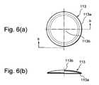
- FIG. 6has views showing the first embodiment of the present invention, in which, FIG. 6( a ) is a plan view of a second contact spring, and FIG. 6( b ) is a sectional view as seen by the lines b—b of FIG. 6( a );
- FIG. 7has views showing the first embodiment of the present invention, in which, FIG. 7( a ) is a plan view of the first contact spring, and FIG. 7( b ) is a sectional view as seen by the line b—b of FIG. 7( a );
- FIG. 8is a plan view of a circuit board for portable telephone according to the first embodiment of the present invention.
- FIG. 9is an exploded perspective view of the circuit board for portable telephone according to the first embodiment of the present invention.
- FIG. 10has views showing a second embodiment of the present invention, in which, FIG. 10( a ) is a plan view of a first contact spring, and FIG. 10( b ) is a sectional view as seen by the line b—b of FIG. 10( a );
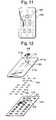
- FIG. 11is a plan view of a circuit board for portable telephone according to a third embodiment of the present invention.
- FIG. 12is an exploded perspective view of the circuit board for portable telephone according to the third embodiment of the present invention.
- FIG. 13is an exploded perspective view showing a structure of a two-step switch according to a fourth embodiment of the present invention.
- FIG. 14is a sectional view of the two-step switch according to the fourth embodiment of the present invention.
- FIG. 15is a sectional view as seen by the line XV—XV of FIG. 14 according to the fourth embodiment of the present invention.
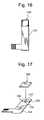
- FIG. 16is a plan view according to a fifth embodiment of the present invention, in which a two-step switch is attached to a circuit board;
- FIG. 17is an exploded perspective view according to the fifth embodiment of the present invention, in which the two-step switch is attached to the circuit board;
- FIG. 18is a perspective view showing a structure of a switch contact spring according to a prior art.
- FIG. 1is an exploded perspective view of a two-step switch 100 according to the first embodiment
- FIG. 2is a plan view of the two-step switch 100
- FIG. 3is a plan view of a printed circuit board
- FIG. 4is a sectional view as seen by the line IV—IV of FIG. 2
- FIG. 5is a sectional view as seen by the line V—V of FIG. 2 .
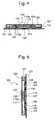
- a printed circuit board 101on which, first fixed contacts 103 , a second fixed contact 105 , and a third fixed contact 107 , are provided.
- the printed circuit board 101has penetrating holes 102 , 102 , at positions diametrically opposite to each other, into which fixing screws (not shown) are inserted respectively.
- the adhesive sheet 109serving as a second insulation sheet, positioned above the printed circuit board 101 .
- the adhesive sheet 109has an opening 111 .
- the opening 111comprises, a circular opening 111 a at the center thereof, and a pair of rectangular openings 111 b , 111 b continuously formed at the outer part of the circular opening 111 a .
- the adhesive sheet 109also has penetrating holes 112 , 112 , at positions diametrically opposite to each other, into which the fixing screws (not shown) are inserted respectively.
- the second contact spring 113there is a second contact spring 113 , at the position of the circular opening 111 a of the opening 111 of the adhesive sheet 109 .
- the second contact spring 113is in a dome shape, protruding in the upward direction of FIG. 1 .
- the second contact spring 113has an outer peripheral contact 113 a at the outer periphery, and also has an inner contact 113 b at the inner part.
- the outer peripheral contact 113 a of the second contact spring 113is in regular contact with the second contact 105 of the circuit board 101 .
- the adhesive sheet 115serving as a first insulation sheet, positioned above the second contact spring 113 .
- the adhesive sheet 115has a circular opening 117 at the center thereof.
- the adhesive sheet 115also has penetrating holes 120 , 120 , at positions diametrically opposite to each other, into which the fixing screws (not shown) are inserted respectively.
- first contact spring 121positioned above the adhesive sheet 115 .
- the first contact spring 121is substantially in a dome shape, protruding in the upward direction of FIG. 1 .
- the both ends at the outer periphery of the first contact spring 121 , facing opposite to each other,have been formed in bowing shapes, serving as outer peripheral contacts 123 , 123 .
- FIG. 1illustrates a first contact spring 121 , positioned above the adhesive sheet 115 .
- the first contact spring 121is substantially in a dome shape, protruding in the upward direction of FIG. 1 .
- the both ends at the outer periphery of the first contact spring 121facing opposite to each other, have been formed in bowing shapes, serving as outer peripheral contacts 123 , 123 .
- the outer peripheral contacts 123 , 123are in regular contact with the first fixed contacts 103 , 103 , via the openings 119 , 119 of the adhesive sheet 115 , and via the openings 111 b , 111 b of the adhesive sheet 109 .
- the inner contact 125is reversed by depressing operation, and becomes in contact with the inner contact 113 b of the second contact spring 113 , via the circular opening 117 of the adhesive sheet 115 .
- Thisis a first-stage motion, whereby a first electric circuit (not shown) is actuated.
- the second contact spring 113is then reversed, whereby the reverse side of the inner contact 113 b of the second contact spring 113 becomes in contact with the third fixed contact 107 of the circuit board 101 .
- a second electric circuit(not shown) is actuated.
- the inner contact 125is formed in a shape of bridge, and openings 126 , 126 are formed on the both sides of the inner contact 125 .
- the spacer 127there is a spacer 127 above the first contact spring 121 , and there is also a cover film 129 provided above the spacer 127 .
- the spacer 127has a circular opening 131 .
- the cover film 129serves as a dust prevention cover.
- the spacer 127also has penetrating holes 128 , 128 , at positions diametrically opposite to each other, into which the fixing screws (not shown) are inserted respectively.
- the cover film 129has penetrating holes 130 , 130 , into which the fixing screws (not shown) are inserted.
- FIG. 8is a plan view of a printed circuit board and adjacent structure for a portable telephone
- FIG. 9is an exploded perspective view of the printed circuit board and adjacent structure for the portable telephone.
- dome contacts 141are provided above the printed circuit board 101 .
- adhesive tape 109above the dome contacts 141 .
- the printed circuit board 101 and the adhesive tape 109respectively have bent parts 143 , 145 , so that these bent parts 143 , 145 are stacked and bent at right angle. These bent parts serve as a side surface part of a portable telephone (not shown). The two-step switch as discussed above is provided at these bent parts.
- the bent part 143has the first fixed contacts 103 , the second fixed contact 105 and the third fixed contact 107 , as explained in FIG. 1 . Further, the other bent part 145 of the adhesive tape 109 has the opening 111 .
- the first embodiment as discussed abovehas the following merits.
- the present inventiondoes not have a double structure of the first contact and the second contact in radial direction likewise the prior art, but has a structure in which the first contact spring 121 and the second contact spring 113 are stacked in perpendicular direction, whereby the size in radial direction will not be increased.
- the thicknesshas been reduced, thus the size of the side surface should be minimized.
- the size in radial direction of the two-step switch according to the prior artis large, it is quite difficult to incorporate the conventional two-step switch in such a narrow space.
- the two-step switch of the present inventionbecause the size in radial direction is reduced, it is possible to be incorporated in such a narrow space easily.
- the first contact spring 121 and the second contact spring 113are provided separately. Thus, it is not necessary to provide, likewise the case of the prior art, two different loading characteristics by a single contact spring. Therefore, the complicated adjustment working is no more required.
- the first contact spring 121has an improved shape, whereby the necessary stroke may be secured.
- the parts in which the outer peripheral contacts 123 , 123 are providedare formed in bowing shapes toward the lower side, and the inner contact 125 is protrusively formed in a bridge shape, thus it is possible to secure the height, i.e., the stroke. Consequently, the different levels are no more required on the fixed contacts of the printed circuit board, i.e., the first fixed contacts 103 , the second fixed contact 105 and the third fixed contact 107 , and it is possible to cope with the printed circuit board 101 in various shapes easily.
- cover film 129may serve as the dust prevention cover.
- the both ends of the first contact spring 121 according to the first embodimentare formed in bowing shapes toward the lower side, at which projecting chips are provided, respectively serving as the outer peripheral contacts 123 , 123 .
- the outer peripheral contacts 123 , 123project, not only in radial direction, but also toward the opposite side of the protruding part. Thus, it is further possible to secure the height, in particular the stroke.
- the two-step switchis positioned on the side surface of the portable telephone.
- the present inventionis not limited to that example.
- the two-step switchis positioned at the upper part of the front surface of a portable telephone. According to the third embodiment, it is also possible to obtain substantially the same effect as those of the first and second embodiments.
- a fourth embodiment of the present inventionwill now be described with reference to FIGS. 13 through 15 .
- the adhesive sheet 109 serving as the second insulation sheet in the first embodimenthas been removed, and only the adhesive sheet 151 serving as the first insulation sheet is provided.
- the shape of the adhesive sheet 151is substantially the same as that of the adhesive sheet 109 of the first embodiment.
- the adhesive sheet 151has a circular opening 153 , and a pair of rectangular openings 155 , 155 are formed at the outside of the circular opening 151 .
- FIG. 14 and FIG. 15respectively show the sectional views of the two-step switch having the above structure.
- the fourth embodimentit is also possible to obtain substantially the same effect as that of the first embodiment. Further, the number of parts regarding the second insulation sheet may be reduced, whereby the facile manufacturing and assembly work may be accomplished, and the production cost may be reduced.
- FIGS. 16 and 17A fifth embodiment of the present invention will now be described with reference to FIGS. 16 and 17 .
- the circuit board 131is provided with fixed contacts 133 , 135 , 137 , to which a two-step switch 100 is attached.
- the fifth embodimentit is also possible to obtain substantially the same effect as that of the first through fourth embodiments.
- the first through fifth embodimentshave been discussed with regard to the two-step switch mounted on the printed circuit of the portable telephone, as an example, but the present invention is not limited to the portable telephone.
- the present inventioncan be applied to various circuit boards, for example, the circuit boards for various electric instruments and apparatus, electronic instruments and apparatus (e.g. digital cameras).
- each elementis merely an example, and various shape and size may be utilized.
Landscapes
- Push-Button Switches (AREA)
Abstract
Description
Claims (20)
Applications Claiming Priority (6)
| Application Number | Priority Date | Filing Date | Title |
|---|---|---|---|
| JP2004070163 | 2004-03-12 | ||
| JP2004-070163 | 2004-03-12 | ||
| JP2004-129639 | 2004-04-26 | ||
| JP2004129639 | 2004-04-26 | ||
| JP2004236359AJP2005340154A (en) | 2004-03-12 | 2004-08-16 | Two-step operation switch |
| JP2004-236359 | 2004-08-16 |
Publications (2)
| Publication Number | Publication Date |
|---|---|
| US6936777B1true US6936777B1 (en) | 2005-08-30 |
| US20050199475A1 US20050199475A1 (en) | 2005-09-15 |
Family
ID=34864950
Family Applications (1)
| Application Number | Title | Priority Date | Filing Date |
|---|---|---|---|
| US10/942,853Expired - Fee RelatedUS6936777B1 (en) | 2004-03-12 | 2004-09-17 | Two-step switch |
Country Status (5)
| Country | Link |
|---|---|
| US (1) | US6936777B1 (en) |
| JP (1) | JP2005340154A (en) |
| KR (1) | KR20050091907A (en) |
| CN (1) | CN100342467C (en) |
| TW (1) | TWI240939B (en) |
Cited By (33)
| Publication number | Priority date | Publication date | Assignee | Title |
|---|---|---|---|---|
| US20050217895A1 (en)* | 2004-04-01 | 2005-10-06 | Arie Maharshak | Flexible printed circuits with many tiny holes |
| US20060113178A1 (en)* | 2004-11-30 | 2006-06-01 | Alps Electric Co., Ltd. | Multistep switch having capacitive type sensor |
| US20060185971A1 (en)* | 2003-09-09 | 2006-08-24 | Sylvain Rochon | Electrical switch device with lateral activation |
| US20060234522A1 (en)* | 2005-04-15 | 2006-10-19 | Innolux Display Corp. | Button module and electronic device using the same |
| US20070007119A1 (en)* | 2005-07-07 | 2007-01-11 | Sylvain Rochon | Miniaturized electric switch |
| US7217893B1 (en)* | 2006-10-13 | 2007-05-15 | Altek Corporation | Two-stage button structure |
| US20070184877A1 (en)* | 2006-02-06 | 2007-08-09 | Lg Electronic Inc. | Mobile terminal key input device and method |
| US20080035462A1 (en)* | 2006-08-10 | 2008-02-14 | Matsushita Electric Industrial Co., Ltd. | Push switch |
| US20090184850A1 (en)* | 2008-01-22 | 2009-07-23 | Verifone, Inc. | Secured keypad devices |
| US20090272640A1 (en)* | 2008-04-30 | 2009-11-05 | Coactive Technologies, Inc. | Electrical switch with detection and an assembly comprising such a detecting switch |
| US20100328113A1 (en)* | 2009-03-26 | 2010-12-30 | Hypercom Corporation | Keypad membrane security |
| US20110215938A1 (en)* | 2010-03-02 | 2011-09-08 | Verifone, Inc. | Point of sale terminal having enhanced security |
| US20110248860A1 (en)* | 2010-04-12 | 2011-10-13 | Amihay Avital | Secure data entry device |
| US20110278144A1 (en)* | 2008-09-30 | 2011-11-17 | Huf Hülsbeck & Fürst Gmbh & Co. Kg | Actuation Unit |
| US20120111712A1 (en)* | 2010-11-09 | 2012-05-10 | CoActive Technologies, LLC | Thin electrical switch |
| US20120193207A1 (en)* | 2009-09-29 | 2012-08-02 | Grg Banking Equipment Co., Ltd | Encryption keyboard |
| US20120241302A1 (en)* | 2011-03-23 | 2012-09-27 | Akira Ishigame | Push-on switch |
| US8405506B2 (en) | 2010-08-02 | 2013-03-26 | Verifone, Inc. | Secure data entry device |
| US8595514B2 (en) | 2008-01-22 | 2013-11-26 | Verifone, Inc. | Secure point of sale terminal |
| US8593824B2 (en) | 2010-10-27 | 2013-11-26 | Verifone, Inc. | Tamper secure circuitry especially for point of sale terminal |
| US8621235B2 (en) | 2011-01-06 | 2013-12-31 | Verifone, Inc. | Secure pin entry device |
| US20140054155A1 (en)* | 2012-08-22 | 2014-02-27 | Junpei KAGEYAMA | Long-stroke dome-shaped movable contact piece |
| US8884757B2 (en) | 2011-07-11 | 2014-11-11 | Verifone, Inc. | Anti-tampering protection assembly |
| US9213869B2 (en) | 2013-10-04 | 2015-12-15 | Verifone, Inc. | Magnetic stripe reading device |
| US9508502B2 (en) | 2012-07-18 | 2016-11-29 | Mec A/S | Push button switch having a curved deformable contact element |
| US9595174B2 (en) | 2015-04-21 | 2017-03-14 | Verifone, Inc. | Point of sale terminal having enhanced security |
| US9691066B2 (en) | 2012-07-03 | 2017-06-27 | Verifone, Inc. | Location-based payment system and method |
| US9711303B2 (en) | 2013-06-27 | 2017-07-18 | Blackberry Limited | Dome-shaped assembly and handheld electronic device including dome-shaped assembly |
| US20180358191A1 (en)* | 2017-06-13 | 2018-12-13 | Trent Zimmer | Multi-pole dome switch |
| US10544923B1 (en) | 2018-11-06 | 2020-01-28 | Verifone, Inc. | Devices and methods for optical-based tamper detection using variable light characteristics |
| US11397835B2 (en) | 2014-07-23 | 2022-07-26 | Verifone, Inc. | Data device including OFN functionality |
| US11487422B2 (en) | 2020-11-03 | 2022-11-01 | Trent Zimmer | Force sensing dome switch |
| US11495418B2 (en)* | 2019-11-20 | 2022-11-08 | Apem | Multipolar switch |
Families Citing this family (6)
| Publication number | Priority date | Publication date | Assignee | Title |
|---|---|---|---|---|
| JP4371987B2 (en)* | 2004-12-07 | 2009-11-25 | ホシデン株式会社 | Push-on switch |
| EP2007117B1 (en)* | 2006-04-11 | 2014-11-12 | NEC Corporation | Operating unit and information processing terminal equipped with it and their assembling methods |
| FR2906930B1 (en)* | 2006-10-06 | 2013-05-31 | Nicomatic Sa | METAL DOME CONTACT COMPONENT AND CARD COMPRISING THE SAME |
| US20080277251A1 (en)* | 2007-05-09 | 2008-11-13 | Snaptron, Inc. | Electrical switch apparatus and methods |
| US20100140065A1 (en)* | 2008-12-08 | 2010-06-10 | Hanbit Precision Co., Ltd. (Republic Of Korea) | Multi-step pressurized switch |
| CN115249596A (en)* | 2021-04-28 | 2022-10-28 | 致伸科技股份有限公司 | Dome switch push button |
Citations (11)
| Publication number | Priority date | Publication date | Assignee | Title |
|---|---|---|---|---|
| US4359614A (en)* | 1981-09-24 | 1982-11-16 | Illinois Tool Works Inc. | Miniature two-level pushbutton switch |
| US4659881A (en)* | 1986-01-27 | 1987-04-21 | Eastman Kodak Company | Multidome multistage switch assembly |
| US5313027A (en)* | 1992-03-16 | 1994-05-17 | Matsushita Electric Industrial Co., Ltd. | Push button switch assembly including single or plural sequentially closed switches |
| US5510584A (en)* | 1995-03-07 | 1996-04-23 | Itt Corporation | Sequentially operated snap action membrane switches |
| US5898147A (en)* | 1997-10-29 | 1999-04-27 | C & K Components, Inc. | Dual tact switch assembly |
| JP2002163952A (en) | 2000-11-24 | 2002-06-07 | Omron Corp | Two-stage action switch and its manufacturing method |
| JP2002352664A (en) | 2001-05-28 | 2002-12-06 | Smk Corp | Push switch |
| US6639159B2 (en)* | 2001-12-14 | 2003-10-28 | Nec Corporation | Key input circuit and portable terminal input device |
| US6747218B2 (en)* | 2002-09-20 | 2004-06-08 | Sherwood Services Ag | Electrosurgical haptic switch including snap dome and printed circuit stepped contact array |
| US6784382B2 (en)* | 2002-03-13 | 2004-08-31 | Matsushita Electric Industrial Co., Ltd. | Push-on switch |
| US6809272B2 (en)* | 2002-10-22 | 2004-10-26 | Smk Corporation | Double action push switch |
Family Cites Families (1)
| Publication number | Priority date | Publication date | Assignee | Title |
|---|---|---|---|---|
| JP2003007168A (en)* | 2001-06-21 | 2003-01-10 | Alps Electric Co Ltd | Push-button switch |
- 2004
- 2004-08-16JPJP2004236359Apatent/JP2005340154A/enactivePending
- 2004-09-17USUS10/942,853patent/US6936777B1/ennot_activeExpired - Fee Related
- 2004-09-24KRKR1020040077117Apatent/KR20050091907A/ennot_activeCeased
- 2004-12-31TWTW093141634Apatent/TWI240939B/ennot_activeIP Right Cessation
- 2005
- 2005-01-14CNCNB2005100021973Apatent/CN100342467C/ennot_activeExpired - Fee Related
Patent Citations (11)
| Publication number | Priority date | Publication date | Assignee | Title |
|---|---|---|---|---|
| US4359614A (en)* | 1981-09-24 | 1982-11-16 | Illinois Tool Works Inc. | Miniature two-level pushbutton switch |
| US4659881A (en)* | 1986-01-27 | 1987-04-21 | Eastman Kodak Company | Multidome multistage switch assembly |
| US5313027A (en)* | 1992-03-16 | 1994-05-17 | Matsushita Electric Industrial Co., Ltd. | Push button switch assembly including single or plural sequentially closed switches |
| US5510584A (en)* | 1995-03-07 | 1996-04-23 | Itt Corporation | Sequentially operated snap action membrane switches |
| US5898147A (en)* | 1997-10-29 | 1999-04-27 | C & K Components, Inc. | Dual tact switch assembly |
| JP2002163952A (en) | 2000-11-24 | 2002-06-07 | Omron Corp | Two-stage action switch and its manufacturing method |
| JP2002352664A (en) | 2001-05-28 | 2002-12-06 | Smk Corp | Push switch |
| US6639159B2 (en)* | 2001-12-14 | 2003-10-28 | Nec Corporation | Key input circuit and portable terminal input device |
| US6784382B2 (en)* | 2002-03-13 | 2004-08-31 | Matsushita Electric Industrial Co., Ltd. | Push-on switch |
| US6747218B2 (en)* | 2002-09-20 | 2004-06-08 | Sherwood Services Ag | Electrosurgical haptic switch including snap dome and printed circuit stepped contact array |
| US6809272B2 (en)* | 2002-10-22 | 2004-10-26 | Smk Corporation | Double action push switch |
Cited By (59)
| Publication number | Priority date | Publication date | Assignee | Title |
|---|---|---|---|---|
| US20060185971A1 (en)* | 2003-09-09 | 2006-08-24 | Sylvain Rochon | Electrical switch device with lateral activation |
| US7157650B2 (en)* | 2003-09-09 | 2007-01-02 | Itt Manufacturing Enterprises, Inc. | Electrical switch device with lateral activation |
| US20050217895A1 (en)* | 2004-04-01 | 2005-10-06 | Arie Maharshak | Flexible printed circuits with many tiny holes |
| US7291795B2 (en)* | 2004-04-01 | 2007-11-06 | Arie Maharshak | Flexible printed circuits with many tiny holes |
| US7166813B2 (en)* | 2004-11-30 | 2007-01-23 | Alps Electric Co., Ltd. | Multistep switch having capacitive type sensor |
| US20060113178A1 (en)* | 2004-11-30 | 2006-06-01 | Alps Electric Co., Ltd. | Multistep switch having capacitive type sensor |
| US20060234522A1 (en)* | 2005-04-15 | 2006-10-19 | Innolux Display Corp. | Button module and electronic device using the same |
| US7196280B2 (en)* | 2005-07-07 | 2007-03-27 | Itt Manufacturing Enterprises, Inc. | Miniaturized electric switch |
| US20070007119A1 (en)* | 2005-07-07 | 2007-01-11 | Sylvain Rochon | Miniaturized electric switch |
| US20070184877A1 (en)* | 2006-02-06 | 2007-08-09 | Lg Electronic Inc. | Mobile terminal key input device and method |
| US7737373B2 (en)* | 2006-02-06 | 2010-06-15 | Lg Electronics Inc. | Mobile terminal key input device and method |
| US20080035462A1 (en)* | 2006-08-10 | 2008-02-14 | Matsushita Electric Industrial Co., Ltd. | Push switch |
| US7429707B2 (en)* | 2006-08-10 | 2008-09-30 | Matsushita Electric Industrial Co., Ltd. | Push switch |
| US7217893B1 (en)* | 2006-10-13 | 2007-05-15 | Altek Corporation | Two-stage button structure |
| US9250709B2 (en) | 2008-01-22 | 2016-02-02 | Verifone, Inc. | Secure point of sale terminal |
| US9013336B2 (en) | 2008-01-22 | 2015-04-21 | Verifone, Inc. | Secured keypad devices |
| US9032222B2 (en) | 2008-01-22 | 2015-05-12 | Verifone, Inc. | Secure point of sale terminal |
| US9779270B2 (en) | 2008-01-22 | 2017-10-03 | Verifone, Inc. | Secured keypad devices |
| US20090184850A1 (en)* | 2008-01-22 | 2009-07-23 | Verifone, Inc. | Secured keypad devices |
| US9436293B2 (en) | 2008-01-22 | 2016-09-06 | Verifone, Inc. | Secured keypad devices |
| US8595514B2 (en) | 2008-01-22 | 2013-11-26 | Verifone, Inc. | Secure point of sale terminal |
| US20090272640A1 (en)* | 2008-04-30 | 2009-11-05 | Coactive Technologies, Inc. | Electrical switch with detection and an assembly comprising such a detecting switch |
| US20110278144A1 (en)* | 2008-09-30 | 2011-11-17 | Huf Hülsbeck & Fürst Gmbh & Co. Kg | Actuation Unit |
| US8809710B2 (en)* | 2008-09-30 | 2014-08-19 | Huf Hülsbeck & Fürst Gmbh & Co. Kg | Actuation unit |
| US8432300B2 (en) | 2009-03-26 | 2013-04-30 | Hypercom Corporation | Keypad membrane security |
| US20100328113A1 (en)* | 2009-03-26 | 2010-12-30 | Hypercom Corporation | Keypad membrane security |
| US20120193207A1 (en)* | 2009-09-29 | 2012-08-02 | Grg Banking Equipment Co., Ltd | Encryption keyboard |
| US8772653B2 (en)* | 2009-09-29 | 2014-07-08 | Grg Banking Equipment Co., Ltd. | Encryption keyboard |
| US8760292B2 (en) | 2010-03-02 | 2014-06-24 | Verifone, Inc. | Point of sale terminal having enhanced security |
| US8358218B2 (en) | 2010-03-02 | 2013-01-22 | Verifone, Inc. | Point of sale terminal having enhanced security |
| US9275528B2 (en) | 2010-03-02 | 2016-03-01 | Verifone, Inc. | Point of sale terminal having enhanced security |
| US8988233B2 (en) | 2010-03-02 | 2015-03-24 | Verifone, Inc. | Point of sale terminal having enhanced security |
| US20110215938A1 (en)* | 2010-03-02 | 2011-09-08 | Verifone, Inc. | Point of sale terminal having enhanced security |
| US8330606B2 (en)* | 2010-04-12 | 2012-12-11 | Verifone, Inc. | Secure data entry device |
| US20110248860A1 (en)* | 2010-04-12 | 2011-10-13 | Amihay Avital | Secure data entry device |
| US8710987B2 (en) | 2010-08-02 | 2014-04-29 | Verifone, Inc. | Secure data entry device |
| US8405506B2 (en) | 2010-08-02 | 2013-03-26 | Verifone, Inc. | Secure data entry device |
| US8593824B2 (en) | 2010-10-27 | 2013-11-26 | Verifone, Inc. | Tamper secure circuitry especially for point of sale terminal |
| US9012796B2 (en)* | 2010-11-09 | 2015-04-21 | CoActive Technologies, LLC | Thin electrical switch |
| US20120111712A1 (en)* | 2010-11-09 | 2012-05-10 | CoActive Technologies, LLC | Thin electrical switch |
| US8954750B2 (en) | 2011-01-06 | 2015-02-10 | Verifone, Inc. | Secure PIN entry device |
| US9792803B2 (en) | 2011-01-06 | 2017-10-17 | Verifone, Inc. | Secure PIN entry device |
| US8621235B2 (en) | 2011-01-06 | 2013-12-31 | Verifone, Inc. | Secure pin entry device |
| US8698028B2 (en)* | 2011-03-23 | 2014-04-15 | Panasonic Corporation | Push-on switch |
| US20120241302A1 (en)* | 2011-03-23 | 2012-09-27 | Akira Ishigame | Push-on switch |
| US8884757B2 (en) | 2011-07-11 | 2014-11-11 | Verifone, Inc. | Anti-tampering protection assembly |
| US9390601B2 (en) | 2011-07-11 | 2016-07-12 | Verifone, Inc. | Anti-tampering protection assembly |
| US9691066B2 (en) | 2012-07-03 | 2017-06-27 | Verifone, Inc. | Location-based payment system and method |
| US9508502B2 (en) | 2012-07-18 | 2016-11-29 | Mec A/S | Push button switch having a curved deformable contact element |
| US20140054155A1 (en)* | 2012-08-22 | 2014-02-27 | Junpei KAGEYAMA | Long-stroke dome-shaped movable contact piece |
| US9711303B2 (en) | 2013-06-27 | 2017-07-18 | Blackberry Limited | Dome-shaped assembly and handheld electronic device including dome-shaped assembly |
| US9213869B2 (en) | 2013-10-04 | 2015-12-15 | Verifone, Inc. | Magnetic stripe reading device |
| US11397835B2 (en) | 2014-07-23 | 2022-07-26 | Verifone, Inc. | Data device including OFN functionality |
| US9595174B2 (en) | 2015-04-21 | 2017-03-14 | Verifone, Inc. | Point of sale terminal having enhanced security |
| US20180358191A1 (en)* | 2017-06-13 | 2018-12-13 | Trent Zimmer | Multi-pole dome switch |
| US10460890B2 (en)* | 2017-06-13 | 2019-10-29 | Trent Zimmer | Multi-pole dome switch |
| US10544923B1 (en) | 2018-11-06 | 2020-01-28 | Verifone, Inc. | Devices and methods for optical-based tamper detection using variable light characteristics |
| US11495418B2 (en)* | 2019-11-20 | 2022-11-08 | Apem | Multipolar switch |
| US11487422B2 (en) | 2020-11-03 | 2022-11-01 | Trent Zimmer | Force sensing dome switch |
Also Published As
| Publication number | Publication date |
|---|---|
| CN1667769A (en) | 2005-09-14 |
| CN100342467C (en) | 2007-10-10 |
| TWI240939B (en) | 2005-10-01 |
| US20050199475A1 (en) | 2005-09-15 |
| TW200531104A (en) | 2005-09-16 |
| JP2005340154A (en) | 2005-12-08 |
| KR20050091907A (en) | 2005-09-15 |
Similar Documents
| Publication | Publication Date | Title |
|---|---|---|
| US6936777B1 (en) | Two-step switch | |
| US7635817B2 (en) | Combined switch | |
| KR100834633B1 (en) | Keypad combination structure of mobile terminal | |
| US6841744B1 (en) | Slide switch and manufacturing method of the same | |
| US7929319B2 (en) | Positioning structure for portable electronic device | |
| CN101925971A (en) | Key Switches and Electronics | |
| US20090308725A1 (en) | Push switch | |
| US8098494B2 (en) | Electronic device | |
| JP5111937B2 (en) | Portable electronic devices | |
| JP5177423B2 (en) | Switch and electronic device having the same | |
| US7057128B1 (en) | Push-on switch | |
| US6191372B1 (en) | Switch device capable of maintaining stable knob operability over long term | |
| US20060097035A1 (en) | Size effective keypad switching and backlighting scheme | |
| JP5555547B2 (en) | Key switch | |
| JP4652168B2 (en) | Portable electronic devices | |
| JP3720588B2 (en) | Mobile phone | |
| JP5147602B2 (en) | Electronics | |
| JP4545693B2 (en) | Portable electronic devices | |
| CN102595769A (en) | Portable electronic device and printed circuit board module | |
| JP2007184161A (en) | Switching device | |
| KR200263754Y1 (en) | Tact switch form pcb printed circuit board | |
| JP4252509B2 (en) | Keyboard device | |
| JP4436292B2 (en) | Electronics | |
| US7157657B2 (en) | Mobile electronic device and button assembly thereof | |
| JP2007073430A (en) | Key top structure |
Legal Events
| Date | Code | Title | Description |
|---|---|---|---|
| AS | Assignment | Owner name:FUJI ELECTRONICS INDUSTRIES CO., LTD., JAPAN Free format text:ASSIGNMENT OF ASSIGNORS INTEREST;ASSIGNOR:KAWAKUBO, NOBORU;REEL/FRAME:015807/0644 Effective date:20040816 | |
| FEPP | Fee payment procedure | Free format text:PAYOR NUMBER ASSIGNED (ORIGINAL EVENT CODE: ASPN); ENTITY STATUS OF PATENT OWNER: LARGE ENTITY | |
| FPAY | Fee payment | Year of fee payment:4 | |
| AS | Assignment | Owner name:FEI HOLDINGS KABUSHIKI KAISHA, JAPAN Free format text:MERGER;ASSIGNOR:FUJI ELECTRONICS INDUSTRIES CO., LTD.;REEL/FRAME:029048/0001 Effective date:20120401 | |
| AS | Assignment | Owner name:FEI HOLDINGS KABUSHIKI KAISHA, JAPAN Free format text:MERGER;ASSIGNOR:FUJI ELECTRONICS INDUSTRIES CO., LTD.;REEL/FRAME:029072/0970 Effective date:20120401 Owner name:FUJI ELECTRONICS INDUSTRIES KABUSHIKI KAISHA, JAPA Free format text:CHANGE OF NAME;ASSIGNOR:FEI HOLDINGS KABUSHIKI KAISHA;REEL/FRAME:029073/0789 Effective date:20120401 | |
| FPAY | Fee payment | Year of fee payment:8 | |
| REMI | Maintenance fee reminder mailed | ||
| LAPS | Lapse for failure to pay maintenance fees | Free format text:PATENT EXPIRED FOR FAILURE TO PAY MAINTENANCE FEES (ORIGINAL EVENT CODE: EXP.) | |
| STCH | Information on status: patent discontinuation | Free format text:PATENT EXPIRED DUE TO NONPAYMENT OF MAINTENANCE FEES UNDER 37 CFR 1.362 | |
| FP | Lapsed due to failure to pay maintenance fee | Effective date:20170830 |