US6936476B1 - Point of care diagnostic systems - Google Patents
Point of care diagnostic systemsDownload PDFInfo
- Publication number
- US6936476B1 US6936476B1US09/717,355US71735500AUS6936476B1US 6936476 B1US6936476 B1US 6936476B1US 71735500 AUS71735500 AUS 71735500AUS 6936476 B1US6936476 B1US 6936476B1
- Authority
- US
- United States
- Prior art keywords
- light
- reader
- sample
- fiberoptic
- test
- Prior art date
- Legal status (The legal status is an assumption and is not a legal conclusion. Google has not performed a legal analysis and makes no representation as to the accuracy of the status listed.)
- Expired - Lifetime, expires
Links
- 238000012360testing methodMethods0.000claimsabstractdescription251
- 238000000034methodMethods0.000claimsabstractdescription128
- 238000003745diagnosisMethods0.000claimsabstractdescription21
- 238000012502risk assessmentMethods0.000claimsabstractdescription13
- 238000013528artificial neural networkMethods0.000claimsdescription64
- 239000004020conductorSubstances0.000claimsdescription55
- 108010067306FibronectinsProteins0.000claimsdescription45
- 102000016359FibronectinsHuman genes0.000claimsdescription45
- 239000012491analyteSubstances0.000claimsdescription43
- 230000001605fetal effectEffects0.000claimsdescription42
- 238000004422calculation algorithmMethods0.000claimsdescription21
- 230000035935pregnancyEffects0.000claimsdescription17
- 238000005259measurementMethods0.000claimsdescription15
- 238000009826distributionMethods0.000claimsdescription12
- 238000007620mathematical functionMethods0.000claimsdescription9
- 230000002829reductive effectEffects0.000claimsdescription9
- 238000012417linear regressionMethods0.000claimsdescription8
- 238000012125lateral flow testMethods0.000claimsdescription7
- 201000003511ectopic pregnancyDiseases0.000claimsdescription5
- 210000002219extraembryonic membraneAnatomy0.000claimsdescription5
- 208000006399Premature Obstetric LaborDiseases0.000claimsdescription4
- 201000011461pre-eclampsiaDiseases0.000claimsdescription3
- 230000004044responseEffects0.000claimsdescription3
- 230000035558fertilityEffects0.000claimsdescription2
- 230000006698inductionEffects0.000claimsdescription2
- 230000036512infertilityEffects0.000claimsdescription2
- 208000000509infertilityDiseases0.000claimsdescription2
- 231100000535infertilityToxicity0.000claimsdescription2
- 238000003018immunoassayMethods0.000abstractdescription120
- 238000003556assayMethods0.000abstractdescription68
- 230000008569processEffects0.000abstractdescription27
- 238000002405diagnostic procedureMethods0.000abstractdescription13
- 239000000523sampleSubstances0.000description105
- 230000006870functionEffects0.000description46
- 238000001514detection methodMethods0.000description33
- 229920000126latexPolymers0.000description27
- 239000004816latexSubstances0.000description27
- 238000012545processingMethods0.000description27
- 239000000020NitrocelluloseSubstances0.000description24
- 229920001220nitrocellulosPolymers0.000description24
- 238000013096assay testMethods0.000description23
- 239000002245particleSubstances0.000description23
- 239000000835fiberSubstances0.000description22
- 239000000463materialSubstances0.000description21
- 208000037265diseases, disorders, signs and symptomsDiseases0.000description19
- 239000000427antigenSubstances0.000description18
- 108091007433antigensProteins0.000description18
- 102000036639antigensHuman genes0.000description18
- 239000000243solutionSubstances0.000description17
- 239000012528membraneSubstances0.000description15
- 238000012549trainingMethods0.000description15
- 210000004379membraneAnatomy0.000description14
- 239000007787solidSubstances0.000description14
- PCHJSUWPFVWCPO-UHFFFAOYSA-NgoldChemical compound[Au]PCHJSUWPFVWCPO-UHFFFAOYSA-N0.000description13
- 239000002250absorbentSubstances0.000description12
- 230000002745absorbentEffects0.000description12
- 229940127121immunoconjugateDrugs0.000description12
- 239000013307optical fiberSubstances0.000description12
- 230000027455bindingEffects0.000description11
- 230000000875corresponding effectEffects0.000description10
- 208000035475disorderDiseases0.000description10
- 235000018102proteinsNutrition0.000description10
- 102000004169proteins and genesHuman genes0.000description10
- 241000283707CapraSpecies0.000description9
- 238000004458analytical methodMethods0.000description9
- 238000010876biochemical testMethods0.000description9
- 201000010099diseaseDiseases0.000description9
- 239000012530fluidSubstances0.000description9
- 238000003780insertionMethods0.000description9
- 230000037431insertionEffects0.000description9
- 239000011159matrix materialSubstances0.000description9
- 230000001537neural effectEffects0.000description9
- 239000013610patient sampleSubstances0.000description9
- 229920003023plasticPolymers0.000description9
- 239000004033plasticSubstances0.000description9
- 108090000623proteins and genesProteins0.000description9
- 230000009467reductionEffects0.000description9
- -1but not limited toPolymers0.000description8
- 238000012546transferMethods0.000description8
- 238000010200validation analysisMethods0.000description8
- 229920002678cellulosePolymers0.000description7
- 239000003153chemical reaction reagentSubstances0.000description7
- 238000005286illuminationMethods0.000description7
- 239000007788liquidSubstances0.000description7
- 239000013642negative controlSubstances0.000description7
- 239000013641positive controlSubstances0.000description7
- LMDZBCPBFSXMTL-UHFFFAOYSA-N1-ethyl-3-(3-dimethylaminopropyl)carbodiimideChemical compoundCCN=C=NCCCN(C)CLMDZBCPBFSXMTL-UHFFFAOYSA-N0.000description6
- 239000001913celluloseSubstances0.000description6
- 238000007405data analysisMethods0.000description6
- 239000000975dyeSubstances0.000description6
- 230000007246mechanismEffects0.000description6
- 238000012123point-of-care testingMethods0.000description6
- 239000011324beadSubstances0.000description5
- 230000008859changeEffects0.000description5
- 239000000123paperSubstances0.000description5
- 239000011347resinSubstances0.000description5
- 229920005989resinPolymers0.000description5
- 210000002966serumAnatomy0.000description5
- 239000000126substanceSubstances0.000description5
- DHMQDGOQFOQNFH-UHFFFAOYSA-NGlycineChemical compoundNCC(O)=ODHMQDGOQFOQNFH-UHFFFAOYSA-N0.000description4
- 101001027128Homo sapiens FibronectinProteins0.000description4
- XUIMIQQOPSSXEZ-UHFFFAOYSA-NSiliconChemical compound[Si]XUIMIQQOPSSXEZ-UHFFFAOYSA-N0.000description4
- 230000002776aggregationEffects0.000description4
- 238000004220aggregationMethods0.000description4
- 239000012472biological sampleSubstances0.000description4
- 239000001045blue dyeSubstances0.000description4
- 238000004364calculation methodMethods0.000description4
- 238000004891communicationMethods0.000description4
- 230000001276controlling effectEffects0.000description4
- 229920001577copolymerPolymers0.000description4
- 230000002596correlated effectEffects0.000description4
- 238000010168coupling processMethods0.000description4
- 230000000694effectsEffects0.000description4
- 239000000499gelSubstances0.000description4
- 239000003365glass fiberSubstances0.000description4
- 239000010931goldSubstances0.000description4
- 229910052737goldInorganic materials0.000description4
- 238000004519manufacturing processMethods0.000description4
- 238000012986modificationMethods0.000description4
- 230000004048modificationEffects0.000description4
- 102000039446nucleic acidsHuman genes0.000description4
- 108020004707nucleic acidsProteins0.000description4
- 150000007523nucleic acidsChemical class0.000description4
- 238000005457optimizationMethods0.000description4
- YBYRMVIVWMBXKQ-UHFFFAOYSA-Nphenylmethanesulfonyl fluorideChemical compoundFS(=O)(=O)CC1=CC=CC=C1YBYRMVIVWMBXKQ-UHFFFAOYSA-N0.000description4
- 229920000036polyvinylpyrrolidonePolymers0.000description4
- 239000001267polyvinylpyrrolidoneSubstances0.000description4
- 235000013855polyvinylpyrrolidoneNutrition0.000description4
- 230000002441reversible effectEffects0.000description4
- 239000010703siliconSubstances0.000description4
- 229910052710siliconInorganic materials0.000description4
- 102000011022Chorionic GonadotropinHuman genes0.000description3
- 108010062540Chorionic GonadotropinProteins0.000description3
- 108090000790EnzymesProteins0.000description3
- 102000004190EnzymesHuman genes0.000description3
- 239000004793PolystyreneSubstances0.000description3
- 239000000872bufferSubstances0.000description3
- 150000001718carbodiimidesChemical class0.000description3
- 239000000919ceramicSubstances0.000description3
- 238000006243chemical reactionMethods0.000description3
- 230000021615conjugationEffects0.000description3
- 230000008878couplingEffects0.000description3
- 238000005859coupling reactionMethods0.000description3
- 238000013479data entryMethods0.000description3
- 238000013461designMethods0.000description3
- 238000010586diagramMethods0.000description3
- 230000005670electromagnetic radiationEffects0.000description3
- 238000011156evaluationMethods0.000description3
- 229940084986human chorionic gonadotropinDrugs0.000description3
- 239000002184metalSubstances0.000description3
- 229910052751metalInorganic materials0.000description3
- 239000000203mixtureSubstances0.000description3
- 230000009871nonspecific bindingEffects0.000description3
- 230000003287optical effectEffects0.000description3
- 229920002223polystyrenePolymers0.000description3
- 229920002451polyvinyl alcoholPolymers0.000description3
- 235000019422polyvinyl alcoholNutrition0.000description3
- 210000003296salivaAnatomy0.000description3
- 239000004094surface-active agentSubstances0.000description3
- 238000009827uniform distributionMethods0.000description3
- 229920002554vinyl polymerPolymers0.000description3
- MYRTYDVEIRVNKP-UHFFFAOYSA-N1,2-DivinylbenzeneChemical compoundC=CC1=CC=CC=C1C=CMYRTYDVEIRVNKP-UHFFFAOYSA-N0.000description2
- 241000894006BacteriaSpecies0.000description2
- 108090000695CytokinesProteins0.000description2
- 102000004127CytokinesHuman genes0.000description2
- 229920002307DextranPolymers0.000description2
- SXRSQZLOMIGNAQ-UHFFFAOYSA-NGlutaraldehydeChemical compoundO=CCCCC=OSXRSQZLOMIGNAQ-UHFFFAOYSA-N0.000description2
- 239000004471GlycineSubstances0.000description2
- 241000725303Human immunodeficiency virusSpecies0.000description2
- 239000004372Polyvinyl alcoholSubstances0.000description2
- VYPSYNLAJGMNEJ-UHFFFAOYSA-NSilicium dioxideChemical compoundO=[Si]=OVYPSYNLAJGMNEJ-UHFFFAOYSA-N0.000description2
- FAPWRFPIFSIZLT-UHFFFAOYSA-MSodium chlorideChemical compound[Na+].[Cl-]FAPWRFPIFSIZLT-UHFFFAOYSA-M0.000description2
- PPBRXRYQALVLMV-UHFFFAOYSA-NStyreneChemical compoundC=CC1=CC=CC=C1PPBRXRYQALVLMV-UHFFFAOYSA-N0.000description2
- 239000007983Tris bufferSubstances0.000description2
- 230000003044adaptive effectEffects0.000description2
- 210000004381amniotic fluidAnatomy0.000description2
- 230000003321amplificationEffects0.000description2
- 235000021120animal proteinNutrition0.000description2
- 230000005540biological transmissionEffects0.000description2
- 210000004369bloodAnatomy0.000description2
- 239000008280bloodSubstances0.000description2
- 230000036772blood pressureEffects0.000description2
- 125000003178carboxy groupChemical group[H]OC(*)=O0.000description2
- 230000001413cellular effectEffects0.000description2
- 238000007398colorimetric assayMethods0.000description2
- 150000001875compoundsChemical class0.000description2
- 210000002808connective tissueAnatomy0.000description2
- 239000007822coupling agentSubstances0.000description2
- CVSVTCORWBXHQV-UHFFFAOYSA-NcreatineChemical compoundNC(=[NH2+])N(C)CC([O-])=OCVSVTCORWBXHQV-UHFFFAOYSA-N0.000description2
- 230000007423decreaseEffects0.000description2
- 230000001419dependent effectEffects0.000description2
- 238000011161developmentMethods0.000description2
- 229940079593drugDrugs0.000description2
- 239000003814drugSubstances0.000description2
- 235000013399edible fruitsNutrition0.000description2
- 125000000524functional groupChemical group0.000description2
- 239000011521glassSubstances0.000description2
- 230000036046immunoreactionEffects0.000description2
- 239000003547immunosorbentSubstances0.000description2
- 230000006872improvementEffects0.000description2
- 238000002372labellingMethods0.000description2
- 239000004973liquid crystal related substanceSubstances0.000description2
- 230000008774maternal effectEffects0.000description2
- 150000002734metacrylic acid derivativesChemical class0.000description2
- 208000010125myocardial infarctionDiseases0.000description2
- 238000003199nucleic acid amplification methodMethods0.000description2
- 108010067933oncofetal fibronectinProteins0.000description2
- 230000036961partial effectEffects0.000description2
- 230000037361pathwayEffects0.000description2
- 230000008447perceptionEffects0.000description2
- 210000002826placentaAnatomy0.000description2
- 210000002381plasmaAnatomy0.000description2
- 229920002401polyacrylamidePolymers0.000description2
- 229920000642polymerPolymers0.000description2
- 239000011148porous materialSubstances0.000description2
- 238000011045prefiltrationMethods0.000description2
- 239000013074reference sampleSubstances0.000description2
- 230000000717retained effectEffects0.000description2
- 230000035945sensitivityEffects0.000description2
- 238000010206sensitivity analysisMethods0.000description2
- 238000001179sorption measurementMethods0.000description2
- 239000000758substrateSubstances0.000description2
- 239000012780transparent materialSubstances0.000description2
- LENZDBCJOHFCAS-UHFFFAOYSA-NtrisChemical compoundOCC(N)(CO)COLENZDBCJOHFCAS-UHFFFAOYSA-N0.000description2
- 210000004881tumor cellAnatomy0.000description2
- 210000002700urineAnatomy0.000description2
- SMZOUWXMTYCWNB-UHFFFAOYSA-N2-(2-methoxy-5-methylphenyl)ethanamineChemical compoundCOC1=CC=C(C)C=C1CCNSMZOUWXMTYCWNB-UHFFFAOYSA-N0.000description1
- NIXOWILDQLNWCW-UHFFFAOYSA-N2-Propenoic acidNatural productsOC(=O)C=CNIXOWILDQLNWCW-UHFFFAOYSA-N0.000description1
- HRPVXLWXLXDGHG-UHFFFAOYSA-NAcrylamideChemical compoundNC(=O)C=CHRPVXLWXLXDGHG-UHFFFAOYSA-N0.000description1
- 239000004925Acrylic resinSubstances0.000description1
- 229920000178Acrylic resinPolymers0.000description1
- 229920000936AgarosePolymers0.000description1
- 108010088751AlbuminsProteins0.000description1
- 102000009027AlbuminsHuman genes0.000description1
- 102100040214Apolipoprotein(a)Human genes0.000description1
- 108010012927Apoprotein(a)Proteins0.000description1
- 108010039627AprotininProteins0.000description1
- 206010003445AscitesDiseases0.000description1
- 241000283690Bos taurusSpecies0.000description1
- OKTJSMMVPCPJKN-UHFFFAOYSA-NCarbonChemical compound[C]OKTJSMMVPCPJKN-UHFFFAOYSA-N0.000description1
- 241000606161ChlamydiaSpecies0.000description1
- KRKNYBCHXYNGOX-UHFFFAOYSA-KCitrateChemical compound[O-]C(=O)CC(O)(CC([O-])=O)C([O-])=OKRKNYBCHXYNGOX-UHFFFAOYSA-K0.000description1
- 238000001712DNA sequencingMethods0.000description1
- 229920004934Dacron®Polymers0.000description1
- KCXVZYZYPLLWCC-UHFFFAOYSA-NEDTAChemical compoundOC(=O)CN(CC(O)=O)CCN(CC(O)=O)CC(O)=OKCXVZYZYPLLWCC-UHFFFAOYSA-N0.000description1
- 238000012286ELISA AssayMethods0.000description1
- 241000588724Escherichia coliSpecies0.000description1
- 206010016194False labourDiseases0.000description1
- 206010017533Fungal infectionDiseases0.000description1
- 108010010803GelatinProteins0.000description1
- 102000001554HemoglobinsHuman genes0.000description1
- 108010054147HemoglobinsProteins0.000description1
- 241000238631HexapodaSpecies0.000description1
- 241000282412HomoSpecies0.000description1
- 108060003951ImmunoglobulinProteins0.000description1
- 102000001706Immunoglobulin Fab FragmentsHuman genes0.000description1
- 108010054477Immunoglobulin Fab FragmentsProteins0.000description1
- 102000004375Insulin-like growth factor-binding protein 1Human genes0.000description1
- 108090000957Insulin-like growth factor-binding protein 1Proteins0.000description1
- 102000014150InterferonsHuman genes0.000description1
- 108010050904InterferonsProteins0.000description1
- 108090001005Interleukin-6Proteins0.000description1
- 108010063738InterleukinsProteins0.000description1
- 102000015696InterleukinsHuman genes0.000description1
- 102000001399KallikreinHuman genes0.000description1
- 108060005987KallikreinProteins0.000description1
- 108010033266Lipoprotein(a)Proteins0.000description1
- 102000057248Lipoprotein(a)Human genes0.000description1
- 108090001030LipoproteinsProteins0.000description1
- 102000004895LipoproteinsHuman genes0.000description1
- 102000008072LymphokinesHuman genes0.000description1
- 108010074338LymphokinesProteins0.000description1
- 241000124008MammaliaSpecies0.000description1
- 241000588653NeisseriaSpecies0.000description1
- 206010028980NeoplasmDiseases0.000description1
- 108091005461Nucleic proteinsProteins0.000description1
- 239000004677NylonSubstances0.000description1
- 229910019142PO4Inorganic materials0.000description1
- 208000030852Parasitic diseaseDiseases0.000description1
- 239000004952PolyamideSubstances0.000description1
- 239000004698PolyethyleneSubstances0.000description1
- 239000004743PolypropyleneSubstances0.000description1
- 208000005107Premature BirthDiseases0.000description1
- 208000034804Product quality issuesDiseases0.000description1
- 238000003559RNA-seq methodMethods0.000description1
- 229920000297RayonPolymers0.000description1
- 240000004808Saccharomyces cerevisiaeSpecies0.000description1
- 241000607142SalmonellaSpecies0.000description1
- 241000194017StreptococcusSpecies0.000description1
- 229930006000SucroseNatural products0.000description1
- CZMRCDWAGMRECN-UGDNZRGBSA-NSucroseChemical compoundO[C@H]1[C@H](O)[C@@H](CO)O[C@@]1(CO)O[C@@H]1[C@H](O)[C@@H](O)[C@H](O)[C@@H](CO)O1CZMRCDWAGMRECN-UGDNZRGBSA-N0.000description1
- 101710120037Toxin CcdBProteins0.000description1
- 150000003926acrylamidesChemical class0.000description1
- 150000001252acrylic acid derivativesChemical class0.000description1
- 150000001253acrylic acidsChemical class0.000description1
- 230000004913activationEffects0.000description1
- 239000000853adhesiveSubstances0.000description1
- 230000001070adhesive effectEffects0.000description1
- 230000004520agglutinationEffects0.000description1
- WYTGDNHDOZPMIW-RCBQFDQVSA-NalstonineNatural productsC1=CC2=C3C=CC=CC3=NC2=C2N1C[C@H]1[C@H](C)OC=C(C(=O)OC)[C@H]1C2WYTGDNHDOZPMIW-RCBQFDQVSA-N0.000description1
- 210000001691amnionAnatomy0.000description1
- 238000013459approachMethods0.000description1
- 229960004405aprotininDrugs0.000description1
- 239000007864aqueous solutionSubstances0.000description1
- 239000003125aqueous solventSubstances0.000description1
- 239000007900aqueous suspensionSubstances0.000description1
- 238000002820assay formatMethods0.000description1
- 230000003190augmentative effectEffects0.000description1
- 230000001580bacterial effectEffects0.000description1
- 238000004166bioassayMethods0.000description1
- 210000001124body fluidAnatomy0.000description1
- 239000007853buffer solutionSubstances0.000description1
- 229920005549butyl rubberPolymers0.000description1
- 201000011510cancerDiseases0.000description1
- 229910052799carbonInorganic materials0.000description1
- 239000005018caseinSubstances0.000description1
- BECPQYXYKAMYBN-UHFFFAOYSA-Ncasein, tech.Chemical compoundNCCCCC(C(O)=O)N=C(O)C(CC(O)=O)N=C(O)C(CCC(O)=N)N=C(O)C(CC(C)C)N=C(O)C(CCC(O)=O)N=C(O)C(CC(O)=O)N=C(O)C(CCC(O)=O)N=C(O)C(C(C)O)N=C(O)C(CCC(O)=N)N=C(O)C(CCC(O)=N)N=C(O)C(CCC(O)=N)N=C(O)C(CCC(O)=O)N=C(O)C(CCC(O)=O)N=C(O)C(COP(O)(O)=O)N=C(O)C(CCC(O)=N)N=C(O)C(N)CC1=CC=CC=C1BECPQYXYKAMYBN-UHFFFAOYSA-N0.000description1
- 235000021240caseinsNutrition0.000description1
- 229920002301cellulose acetatePolymers0.000description1
- 229920003086cellulose etherPolymers0.000description1
- 210000001175cerebrospinal fluidAnatomy0.000description1
- 239000003795chemical substances by applicationSubstances0.000description1
- 238000004587chromatography analysisMethods0.000description1
- 238000012875competitive assayMethods0.000description1
- 230000002860competitive effectEffects0.000description1
- 238000002967competitive immunoassayMethods0.000description1
- 230000006835compressionEffects0.000description1
- 238000007906compressionMethods0.000description1
- 238000005094computer simulationMethods0.000description1
- 238000011109contaminationMethods0.000description1
- 230000008602contractionEffects0.000description1
- 239000013068control sampleSubstances0.000description1
- 229960003624creatineDrugs0.000description1
- 239000006046creatineSubstances0.000description1
- 238000007418data miningMethods0.000description1
- 238000003066decision treeMethods0.000description1
- 239000003085diluting agentSubstances0.000description1
- 230000008034disappearanceEffects0.000description1
- MCPLVIGCWWTHFH-UHFFFAOYSA-Mdisodium;4-[4-[[4-(4-sulfoanilino)phenyl]-[4-(4-sulfonatophenyl)azaniumylidenecyclohexa-2,5-dien-1-ylidene]methyl]anilino]benzenesulfonateChemical compound[Na+].[Na+].C1=CC(S(=O)(=O)O)=CC=C1NC1=CC=C(C(=C2C=CC(C=C2)=[NH+]C=2C=CC(=CC=2)S([O-])(=O)=O)C=2C=CC(NC=3C=CC(=CC=3)S([O-])(=O)=O)=CC=2)C=C1MCPLVIGCWWTHFH-UHFFFAOYSA-M0.000description1
- 229940124645emergency medicineDrugs0.000description1
- 230000007613environmental effectEffects0.000description1
- 229940088598enzymeDrugs0.000description1
- 210000003743erythrocyteAnatomy0.000description1
- FJAZVHYPASAQKM-JBAURARKSA-Nestrone 3-O-(beta-D-glucuronide)Chemical compoundC([C@@H]1[C@@H](C2=CC=3)CC[C@]4([C@H]1CCC4=O)C)CC2=CC=3O[C@@H]1O[C@H](C(O)=O)[C@@H](O)[C@H](O)[C@H]1OFJAZVHYPASAQKM-JBAURARKSA-N0.000description1
- 150000002170ethersChemical class0.000description1
- 238000007421fluorometric assayMethods0.000description1
- 235000013305foodNutrition0.000description1
- 239000012634fragmentSubstances0.000description1
- 229920000159gelatinPolymers0.000description1
- 239000008273gelatinSubstances0.000description1
- 235000019322gelatineNutrition0.000description1
- 235000011852gelatine dessertsNutrition0.000description1
- 230000002068genetic effectEffects0.000description1
- 150000004676glycansChemical class0.000description1
- 229940088597hormoneDrugs0.000description1
- 239000005556hormoneSubstances0.000description1
- 230000002519immonomodulatory effectEffects0.000description1
- 102000018358immunoglobulinHuman genes0.000description1
- 229940072221immunoglobulinsDrugs0.000description1
- 230000010365information processingEffects0.000description1
- ZPNFWUPYTFPOJU-LPYSRVMUSA-NiniprolChemical compoundC([C@H]1C(=O)NCC(=O)NCC(=O)N[C@H]2CSSC[C@H]3C(=O)N[C@@H](CCCCN)C(=O)N[C@@H](C)C(=O)N[C@@H](CCCNC(N)=N)C(=O)N[C@H](C(N[C@H](C(=O)N[C@@H](CCCNC(N)=N)C(=O)N[C@@H](CC=4C=CC(O)=CC=4)C(=O)N[C@@H](CC=4C=CC=CC=4)C(=O)N[C@@H](CC=4C=CC(O)=CC=4)C(=O)N[C@@H](CC(N)=O)C(=O)N[C@@H](C)C(=O)N[C@@H](CCCCN)C(=O)N[C@@H](C)C(=O)NCC(=O)N[C@@H](CC(C)C)C(=O)N[C@@H](CSSC[C@H](NC(=O)[C@H](CC(O)=O)NC(=O)[C@H](CCC(O)=O)NC(=O)[C@H](C)NC(=O)[C@H](CO)NC(=O)[C@H](CCCCN)NC(=O)[C@H](CC=4C=CC=CC=4)NC(=O)[C@H](CC(N)=O)NC(=O)[C@H](CC(N)=O)NC(=O)[C@H](CCCNC(N)=N)NC(=O)[C@H](CCCCN)NC(=O)[C@H](C)NC(=O)[C@H](CCCNC(N)=N)NC2=O)C(=O)N[C@@H](CCSC)C(=O)N[C@@H](CCCNC(N)=N)C(=O)N[C@@H]([C@@H](C)O)C(=O)N[C@@H](CSSC[C@H](NC(=O)[C@H](CC=2C=CC=CC=2)NC(=O)[C@H](CC(O)=O)NC(=O)[C@H]2N(CCC2)C(=O)[C@@H](N)CCCNC(N)=N)C(=O)N[C@@H](CC(C)C)C(=O)N[C@@H](CCC(O)=O)C(=O)N2[C@@H](CCC2)C(=O)N2[C@@H](CCC2)C(=O)N[C@@H](CC=2C=CC(O)=CC=2)C(=O)N[C@@H]([C@@H](C)O)C(=O)NCC(=O)N2[C@@H](CCC2)C(=O)N3)C(=O)NCC(=O)NCC(=O)N[C@@H](C)C(O)=O)C(=O)N[C@@H](CCC(N)=O)C(=O)N[C@H](C(=O)N[C@@H](CC=2C=CC=CC=2)C(=O)N[C@H](C(=O)N1)C(C)C)[C@@H](C)O)[C@@H](C)CC)=O)[C@@H](C)CC)C1=CC=C(O)C=C1ZPNFWUPYTFPOJU-LPYSRVMUSA-N0.000description1
- 229910010272inorganic materialInorganic materials0.000description1
- 239000011147inorganic materialSubstances0.000description1
- 229920000592inorganic polymerPolymers0.000description1
- 230000010354integrationEffects0.000description1
- 229940079322interferonDrugs0.000description1
- 229940047122interleukinsDrugs0.000description1
- 208000037805labourDiseases0.000description1
- 150000002632lipidsChemical class0.000description1
- 239000002502liposomeSubstances0.000description1
- 238000010801machine learningMethods0.000description1
- 239000000696magnetic materialSubstances0.000description1
- 230000007257malfunctionEffects0.000description1
- 238000010339medical testMethods0.000description1
- 229910052752metalloidInorganic materials0.000description1
- 150000002738metalloidsChemical class0.000description1
- 150000002739metalsChemical class0.000description1
- 239000004005microsphereSubstances0.000description1
- 230000001617migratory effectEffects0.000description1
- 229940126619mouse monoclonal antibodyDrugs0.000description1
- 238000000491multivariate analysisMethods0.000description1
- 229920005615natural polymerPolymers0.000description1
- 210000002569neuronAnatomy0.000description1
- 230000036963noncompetitive effectEffects0.000description1
- 238000007826nucleic acid assayMethods0.000description1
- 229920001778nylonPolymers0.000description1
- 229920000620organic polymerPolymers0.000description1
- 239000003960organic solventSubstances0.000description1
- 239000000137peptide hydrolase inhibitorSubstances0.000description1
- NBIIXXVUZAFLBC-UHFFFAOYSA-KphosphateChemical compound[O-]P([O-])([O-])=ONBIIXXVUZAFLBC-UHFFFAOYSA-K0.000description1
- 239000010452phosphateSubstances0.000description1
- 230000035479physiological effects, processes and functionsEffects0.000description1
- 229920001308poly(aminoacid)Polymers0.000description1
- 229920002647polyamidePolymers0.000description1
- 229920000515polycarbonatePolymers0.000description1
- 239000004417polycarbonateSubstances0.000description1
- 229920000728polyesterPolymers0.000description1
- 229920000573polyethylenePolymers0.000description1
- 239000005020polyethylene terephthalateSubstances0.000description1
- 102000040430polynucleotideHuman genes0.000description1
- 108091033319polynucleotideProteins0.000description1
- 239000002157polynucleotideSubstances0.000description1
- 229920001155polypropylenePolymers0.000description1
- 229920001282polysaccharidePolymers0.000description1
- 239000005017polysaccharideSubstances0.000description1
- 238000001556precipitationMethods0.000description1
- 238000002360preparation methodMethods0.000description1
- 238000003825pressingMethods0.000description1
- 238000007639printingMethods0.000description1
- 102000004196processed proteins & peptidesHuman genes0.000description1
- 108090000765processed proteins & peptidesProteins0.000description1
- 239000002964rayonSubstances0.000description1
- 230000035484reaction timeEffects0.000description1
- 238000002310reflectometryMethods0.000description1
- 230000028327secretionEffects0.000description1
- 238000012163sequencing techniqueMethods0.000description1
- 239000000377silicon dioxideSubstances0.000description1
- 239000011780sodium chlorideSubstances0.000description1
- 239000008279solSubstances0.000description1
- 230000009870specific bindingEffects0.000description1
- 208000000995spontaneous abortionDiseases0.000description1
- 150000003431steroidsChemical class0.000description1
- 238000003860storageMethods0.000description1
- 239000005720sucroseSubstances0.000description1
- 230000004083survival effectEffects0.000description1
- 210000004243sweatAnatomy0.000description1
- 230000008961swellingEffects0.000description1
- 229920003051synthetic elastomerPolymers0.000description1
- 229920001059synthetic polymerPolymers0.000description1
- 239000005061synthetic rubberSubstances0.000description1
- 210000001138tearAnatomy0.000description1
- 230000001225therapeutic effectEffects0.000description1
- 238000002560therapeutic procedureMethods0.000description1
- 230000007704transitionEffects0.000description1
- 238000002834transmittanceMethods0.000description1
- 230000032258transportEffects0.000description1
- PIEPQKCYPFFYMG-UHFFFAOYSA-Ntris acetateChemical groupCC(O)=O.OCC(N)(CO)COPIEPQKCYPFFYMG-UHFFFAOYSA-N0.000description1
- 238000013024troubleshootingMethods0.000description1
- 238000002604ultrasonographyMethods0.000description1
- 125000000391vinyl groupChemical group[H]C([*])=C([H])[H]0.000description1
- 230000003612virological effectEffects0.000description1
- 238000001429visible spectrumMethods0.000description1
- 238000005406washingMethods0.000description1
Images


Classifications
- G—PHYSICS
- G01—MEASURING; TESTING
- G01N—INVESTIGATING OR ANALYSING MATERIALS BY DETERMINING THEIR CHEMICAL OR PHYSICAL PROPERTIES
- G01N21/00—Investigating or analysing materials by the use of optical means, i.e. using sub-millimetre waves, infrared, visible or ultraviolet light
- G01N21/17—Systems in which incident light is modified in accordance with the properties of the material investigated
- G01N21/47—Scattering, i.e. diffuse reflection
- G01N21/4738—Diffuse reflection, e.g. also for testing fluids, fibrous materials
- G01N21/474—Details of optical heads therefor, e.g. using optical fibres
- G—PHYSICS
- G01—MEASURING; TESTING
- G01N—INVESTIGATING OR ANALYSING MATERIALS BY DETERMINING THEIR CHEMICAL OR PHYSICAL PROPERTIES
- G01N21/00—Investigating or analysing materials by the use of optical means, i.e. using sub-millimetre waves, infrared, visible or ultraviolet light
- G01N21/84—Systems specially adapted for particular applications
- G01N21/8483—Investigating reagent band
- G—PHYSICS
- G01—MEASURING; TESTING
- G01N—INVESTIGATING OR ANALYSING MATERIALS BY DETERMINING THEIR CHEMICAL OR PHYSICAL PROPERTIES
- G01N33/00—Investigating or analysing materials by specific methods not covered by groups G01N1/00 - G01N31/00
- G01N33/48—Biological material, e.g. blood, urine; Haemocytometers
- G01N33/50—Chemical analysis of biological material, e.g. blood, urine; Testing involving biospecific ligand binding methods; Immunological testing
- G01N33/53—Immunoassay; Biospecific binding assay; Materials therefor
- G01N33/543—Immunoassay; Biospecific binding assay; Materials therefor with an insoluble carrier for immobilising immunochemicals
- G01N33/54366—Apparatus specially adapted for solid-phase testing
- G01N33/54386—Analytical elements
- G01N33/54387—Immunochromatographic test strips
- G01N33/54388—Immunochromatographic test strips based on lateral flow
- G—PHYSICS
- G01—MEASURING; TESTING
- G01N—INVESTIGATING OR ANALYSING MATERIALS BY DETERMINING THEIR CHEMICAL OR PHYSICAL PROPERTIES
- G01N33/00—Investigating or analysing materials by specific methods not covered by groups G01N1/00 - G01N31/00
- G01N33/48—Biological material, e.g. blood, urine; Haemocytometers
- G01N33/50—Chemical analysis of biological material, e.g. blood, urine; Testing involving biospecific ligand binding methods; Immunological testing
- G01N33/68—Chemical analysis of biological material, e.g. blood, urine; Testing involving biospecific ligand binding methods; Immunological testing involving proteins, peptides or amino acids
- G01N33/6887—Chemical analysis of biological material, e.g. blood, urine; Testing involving biospecific ligand binding methods; Immunological testing involving proteins, peptides or amino acids from muscle, cartilage or connective tissue
- G—PHYSICS
- G01—MEASURING; TESTING
- G01N—INVESTIGATING OR ANALYSING MATERIALS BY DETERMINING THEIR CHEMICAL OR PHYSICAL PROPERTIES
- G01N33/00—Investigating or analysing materials by specific methods not covered by groups G01N1/00 - G01N31/00
- G01N33/48—Biological material, e.g. blood, urine; Haemocytometers
- G01N33/50—Chemical analysis of biological material, e.g. blood, urine; Testing involving biospecific ligand binding methods; Immunological testing
- G01N33/68—Chemical analysis of biological material, e.g. blood, urine; Testing involving biospecific ligand binding methods; Immunological testing involving proteins, peptides or amino acids
- G01N33/689—Chemical analysis of biological material, e.g. blood, urine; Testing involving biospecific ligand binding methods; Immunological testing involving proteins, peptides or amino acids related to pregnancy or the gonads
- G—PHYSICS
- G16—INFORMATION AND COMMUNICATION TECHNOLOGY [ICT] SPECIALLY ADAPTED FOR SPECIFIC APPLICATION FIELDS
- G16H—HEALTHCARE INFORMATICS, i.e. INFORMATION AND COMMUNICATION TECHNOLOGY [ICT] SPECIALLY ADAPTED FOR THE HANDLING OR PROCESSING OF MEDICAL OR HEALTHCARE DATA
- G16H10/00—ICT specially adapted for the handling or processing of patient-related medical or healthcare data
- G16H10/40—ICT specially adapted for the handling or processing of patient-related medical or healthcare data for data related to laboratory analysis, e.g. patient specimen analysis
- G—PHYSICS
- G16—INFORMATION AND COMMUNICATION TECHNOLOGY [ICT] SPECIALLY ADAPTED FOR SPECIFIC APPLICATION FIELDS
- G16H—HEALTHCARE INFORMATICS, i.e. INFORMATION AND COMMUNICATION TECHNOLOGY [ICT] SPECIALLY ADAPTED FOR THE HANDLING OR PROCESSING OF MEDICAL OR HEALTHCARE DATA
- G16H15/00—ICT specially adapted for medical reports, e.g. generation or transmission thereof
- G—PHYSICS
- G16—INFORMATION AND COMMUNICATION TECHNOLOGY [ICT] SPECIALLY ADAPTED FOR SPECIFIC APPLICATION FIELDS
- G16H—HEALTHCARE INFORMATICS, i.e. INFORMATION AND COMMUNICATION TECHNOLOGY [ICT] SPECIALLY ADAPTED FOR THE HANDLING OR PROCESSING OF MEDICAL OR HEALTHCARE DATA
- G16H30/00—ICT specially adapted for the handling or processing of medical images
- G16H30/40—ICT specially adapted for the handling or processing of medical images for processing medical images, e.g. editing
- G—PHYSICS
- G16—INFORMATION AND COMMUNICATION TECHNOLOGY [ICT] SPECIALLY ADAPTED FOR SPECIFIC APPLICATION FIELDS
- G16H—HEALTHCARE INFORMATICS, i.e. INFORMATION AND COMMUNICATION TECHNOLOGY [ICT] SPECIALLY ADAPTED FOR THE HANDLING OR PROCESSING OF MEDICAL OR HEALTHCARE DATA
- G16H50/00—ICT specially adapted for medical diagnosis, medical simulation or medical data mining; ICT specially adapted for detecting, monitoring or modelling epidemics or pandemics
- G16H50/20—ICT specially adapted for medical diagnosis, medical simulation or medical data mining; ICT specially adapted for detecting, monitoring or modelling epidemics or pandemics for computer-aided diagnosis, e.g. based on medical expert systems
- G—PHYSICS
- G01—MEASURING; TESTING
- G01N—INVESTIGATING OR ANALYSING MATERIALS BY DETERMINING THEIR CHEMICAL OR PHYSICAL PROPERTIES
- G01N2333/00—Assays involving biological materials from specific organisms or of a specific nature
- G01N2333/435—Assays involving biological materials from specific organisms or of a specific nature from animals; from humans
- G01N2333/78—Connective tissue peptides, e.g. collagen, elastin, laminin, fibronectin, vitronectin, cold insoluble globulin [CIG]
- G—PHYSICS
- G01—MEASURING; TESTING
- G01N—INVESTIGATING OR ANALYSING MATERIALS BY DETERMINING THEIR CHEMICAL OR PHYSICAL PROPERTIES
- G01N2800/00—Detection or diagnosis of diseases
- G01N2800/36—Gynecology or obstetrics
- G01N2800/368—Pregnancy complicated by disease or abnormalities of pregnancy, e.g. preeclampsia, preterm labour
- G—PHYSICS
- G16—INFORMATION AND COMMUNICATION TECHNOLOGY [ICT] SPECIALLY ADAPTED FOR SPECIFIC APPLICATION FIELDS
- G16H—HEALTHCARE INFORMATICS, i.e. INFORMATION AND COMMUNICATION TECHNOLOGY [ICT] SPECIALLY ADAPTED FOR THE HANDLING OR PROCESSING OF MEDICAL OR HEALTHCARE DATA
- G16H10/00—ICT specially adapted for the handling or processing of patient-related medical or healthcare data
- G16H10/60—ICT specially adapted for the handling or processing of patient-related medical or healthcare data for patient-specific data, e.g. for electronic patient records
- Y—GENERAL TAGGING OF NEW TECHNOLOGICAL DEVELOPMENTS; GENERAL TAGGING OF CROSS-SECTIONAL TECHNOLOGIES SPANNING OVER SEVERAL SECTIONS OF THE IPC; TECHNICAL SUBJECTS COVERED BY FORMER USPC CROSS-REFERENCE ART COLLECTIONS [XRACs] AND DIGESTS
- Y02—TECHNOLOGIES OR APPLICATIONS FOR MITIGATION OR ADAPTATION AGAINST CLIMATE CHANGE
- Y02A—TECHNOLOGIES FOR ADAPTATION TO CLIMATE CHANGE
- Y02A90/00—Technologies having an indirect contribution to adaptation to climate change
- Y02A90/10—Information and communication technologies [ICT] supporting adaptation to climate change, e.g. for weather forecasting or climate simulation
- Y—GENERAL TAGGING OF NEW TECHNOLOGICAL DEVELOPMENTS; GENERAL TAGGING OF CROSS-SECTIONAL TECHNOLOGIES SPANNING OVER SEVERAL SECTIONS OF THE IPC; TECHNICAL SUBJECTS COVERED BY FORMER USPC CROSS-REFERENCE ART COLLECTIONS [XRACs] AND DIGESTS
- Y10—TECHNICAL SUBJECTS COVERED BY FORMER USPC
- Y10S—TECHNICAL SUBJECTS COVERED BY FORMER USPC CROSS-REFERENCE ART COLLECTIONS [XRACs] AND DIGESTS
- Y10S436/00—Chemistry: analytical and immunological testing
- Y10S436/811—Test for named disease, body condition or organ function
- Y10S436/814—Pregnancy
Definitions
- the present inventionrelates to systems and methods that aid in providing a medical diagnosis or risk assessment for a patient using biochemical and historic patient data, including data from point of care diagnostic tests or assays, and processing the information to give an indication of a medical condition or risk.
- resultsare generally detected visually by human eye.
- resultsare generally detected visually by human eye.
- human perception and judgment involvedthere is significant variance among those interpreting such test results as to whether a color change or other measurable signal has occurred and the degree of such occurrence.
- subjectivity involved in interpreting whether immunoassay results are positive or negativeThis is particularly pronounced where the result is close to a threshold value.
- the varianceis further enhanced when attempts are made to quantitate such assay test results. Accurate results may be critical for certain diagnostic assays.
- fFNfetal fibronectin
- Systems and methods for medical diagnosis or risk assessment for a patientare provided. These systems and methods are designed to be employed at the point of care, such as in emergency rooms, operating rooms, hospital laboratories and other clinical laboratories, doctor's offices, in the field, or in any situation in which a rapid and accurate result is desired.
- the systems and methodsprocess patient data, particularly data from point of care diagnostic tests or assays, including immunoassays, chemical assays, nucleic acid assays, colorimetric assays, fluorometric assays, chemiluminescent and bioluminescent assays, electrocardiograms, X-rays and other such tests, and provide an indication of a medical condition or risk or absence thereof.
- the systemsinclude an instrument for reading or evaluating the test data and software for converting the data into diagnostic or risk assessment information.
- the systemsinclude a test device, such as a test strip, optionally encased in a housing, for analyzing patient samples and obtaining patient data.
- the deviceincludes a symbology, such as a bar code, which is used to associate identifying information, such as intensity value, standard curves, patient information, reagent information and other such information, with the test device.
- the reader in the systemis optionally adapted to read the symbology.
- the systemsoptionally include a decision-support system or systems, such as a neural network, for evaluating the digitized data, and also for subsequent assessment of the data, such as by integration with other patient information, including documents and information in medical records.
- a decision-support system or systemssuch as a neural network
- All software and instrument componentsare preferably included in a single package.
- the softwarecan be contained in a remote computer so that the test data obtained at a point of care can be sent electronically to a processing center for evaluation.
- the systemsoperate on site at the point of care, such as in a doctor's office, or remote therefrom.
- the patient informationincludes data from physical and biochemical tests, such as immunoassays, and from other procedures.
- the testis performed on a patient at the point of care and generates data that can be digitized, such as by an electronic reflectance or transmission reader, which generates a data signal.
- the signalis processed using software employing data reduction and curve fitting algorithms, or a decision support system, such as a trained neural network, or combinations thereof, for converting the signal into data, which is used to aid in diagnosis of a medical condition or determination of a risk of disease.
- a second decision support systemsuch as a neural net, for refinement or enhancement of the assessment.
- systems and methods for detecting and measuring levels of a target analyte in a patient sample, analyzing the resulting data, and providing a diagnosis or risk assessmentinclude an assay device in combination with a reader, particularly a computer-assisted reader, preferably a reflectance reader, and data processing software employing data reduction and curve fitting algorithms, optionally in combination with a trained neural network for accurately determining the presence or concentration of analyte in a biological sample.
- the methodsinclude the steps of performing an assay on a patient sample, reading the data using a reflectance reader and processing the reflectance data using data processing software employing data reduction algorithms.
- the assayis an immunoassay.
- Preferred softwareincludes curve fitting algorithms, optionally in combination with a trained neural network, to determine the presence or amount of analyte in a given sample.
- the data obtained from the readerthen can be further processed by the medical diagnosis system to provide a risk assessment or diagnosis of a medical condition as output.
- the outputcan be used as input into a subsequent decision support system, such as a neural network, that is trained to evaluate such data.
- the assay deviceis a lateral flow test strip, preferably, though not necessarily, encased in a housing, designed to be read by the reader, and the assay is a sandwich immunoassay.
- a patient sampleis contacted with an antibody for a selected target analyte indicative of a disease, disorder or risk thereof.
- the antibodyis preferably labeled by conjugation to a physically detectable label and, upon contacting with the sample containing the target analyte, forms a complex.
- the antibody-analyte complexis then contacted with a second antibody for the antigen, which is immobilized on a solid support.
- the second antibodycaptures the antibody-analyte complex to form an antibody-analyte-antibody sandwich complex, and the resulting complex, which is immobilized on the solid support, is detectable by virtue of the label.
- the test stripis then inserted into a reader, where the signal from the label in the complex is measured.
- the test stripcould be inserted into the reader prior to addition of the sample.
- the housingmay include a symbology, such as a bar code, which is also read by the reader and contains data related to the assay device and/or test run.
- the signal obtainedis processed using data processing software employing data reduction and curve fitting algorithms, optionally in combination with a trained neural network, to give either a positive or negative result, or a quantitative determination of the concentration of analyte in the sample, which is correlated with a result indicative of a risk or presence of a disease or disorder.
- This resultcan optionally be input into a decision support system, and processed to provide an enhanced assessment of the risk of a medical condition as output.
- the entire proceduremay be automated and/or computer-controlled.
- the reflectance readeris adapted to read a symbology on the test device.
- the symbologyis preferably a bar code, which can be read in the same manner that the test strip in the device can be read.
- the reader headscans across a bar code in a stepwise fashion.
- the data collected from the bar codeis transformed into integrated peak information and analyzed as alphanumeric characters, which are related to information related to the particular device and/or test run or other information, including patient information.
- Code 39(a trademark of Interface Mechanism, Inc., Lynnwood, Wash.; see, e.g., U.S. Pat. No. 4,379,224, U.S. Pat. No. 4,438,327, U.S. Pat. No. 4,511,259 or Code 128 bar codes (see, e.g., U.S. Pat. No. 5,227,893) are used.
- the analyte to be detectedis fetal fibronectin (fFN) and the result obtained is a positive or negative indication of pregnancy or the risk of certain pregnancy-related conditions or fertility and infertility-related conditions, including ectopic pregnancy, preterm labor, pre-eclampsia, imminent delivery, term induction and fetal membrane rupture.
- fFNfetal fibronectin
- this testprovides the same clinically relevant information as a fFN ELISA (an enzyme linked immunosorbent sandwich assay (ELISA)) test heretofore available in significantly less time and at the point of care.
- a fFN immunoassayan enzyme linked immunosorbent sandwich assay (ELISA)
- the fFN immunoassayallows the user to test a cervicovaginal swab sample in about 20 minutes.
- additional informationsuch as a more accurate risk assessment or diagnosis, can be obtained.
- the system hereinprovides a means to detect and to quantitate concentrations of fFN throughout pregnancy and to assess the risk and detect conditions associated therewith. Because of the sensitivity of the combination of the reader and devices provided herein, fFN may be monitored throughout pregnancy, including times when it is not detected by less sensitive systems.
- the reflectance reader and test strip deviceare also provided herein. Also provided herein are the neural nets for assessing the data.
- a method for classifying an imageincludes the steps of reducing the image to a set of derived parameters from which the image can be reconstructed within a predetermined degree of tolerance; inputting the derived parameters into a classification neural network; and determining the classification of the image based on the output of the classification neural network.
- the method of reducing the image to a set of derived parametersis achieved by defining a mathematical function that contains a plurality of parameters representative of the image; and optimizing the parameters of the function using a methodology that minimizes the error between the image and a reconstruction of the image using the function.
- the method of reducing the image to a set of derived parametersis achieved by inputting the image into a trained neural network, where the inputs to the network represent the image; the hidden layer of the network is such that the number of hidden elements is smaller than the number of inputs to the network, and the outputs of the network represent reconstruction of the image; and setting the derived parameters to the output values of the trained neural network.
- the method of reducing the image to a set of derived parametersis achieved by defining a neural network in which the inputs to the network are the coordinates of a point in the image, the hidden layer contains a plurality of elements, and the output of the network represents the reconstruction of the associated point in the image; training the neural network so that the error between the network output and the image are minimized for all points in the image and setting the derived parameters to the weights of the hidden layer of the trained neural network.
- the neural networks and computer systems used in the methodsare also provided.
- FIG. 1Ais a top view of an assay test strip, such as an immunoassay test strip;
- FIG. 1Bis a side view of the assay test strip of FIG. 1A ;
- FIG. 2Ais a perspective view of an assay device, including the assay test strip of FIG. 1 A and FIG. 1 B and housing assembly and showing a bar code, which can optionally be affixed to the housing;
- FIG. 2Bis a perspective view of an alternative embodiment of an assay device, including the assay test strip of FIG. 1 A and FIG. 1 B and housing assembly and showing a bar code, which can optionally be affixed to the housing;
- FIG. 3is a perspective view of the assay device of FIG. 2B showing the individual components of the device;
- FIG. 4is a top view of an exemplary housing assembly for the assay test strip of FIGS. 1A and 1B ;
- FIG. 5is a side assembly view of the housing assembly of FIG. 4 ;
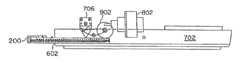
- FIG. 6is a top view of an embodiment of an assay reader and an assay device, inserted therein, in accordance with an exemplary embodiment of the reader;
- FIG. 7is a perspective view of portion of the assay device of FIG. 2A shown inserted into a cassette slot of a lower housing and extending to a reader head assembly within an exemplary embodiment of an assay reader;
- FIG. 8is a top view of the lower housing of the assay reader of FIG. 7 with the assay device inserted therein and a stepper motor shown positioned relative to the assay device as is when the assay device is fully inserted into the cassette slot of the reader;
- FIG. 9is a side view of the lower housing of the reader device of FIG. 7 with the assay device of FIG. 2A fully inserted with the stepper motor shown positioned relative to the fully inserted assay device, with a reader head shown positioned in a lowered position over a test opening of the assay device, and with a carriage wheel shown engaged by the assay device so as to lower the reader head into its lowered position therein;
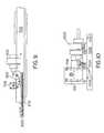
- FIG. 10is a side view of a reader head assembly such as is found in the reader device of FIG. 6 ;
- FIG. 11is a side view of a reader head of the reader head assembly of FIG. 10 ;
- FIG. 12is a reverse angle side view of the reader head assembly of FIG. 10 ;
- FIG. 13is a reverse angle side view of the reader head of FIG. 11 ;
- FIG. 14is a side view of the reader head assembly of FIG. 10 , having been actuated so as to pivot the reader head assembly into a raised position suitable for insertion and removal of the assay device into and from the reader head assembly within the assay reader;
- FIG. 15is an end view of the reader head of FIG. 11 ;
- FIG. 16is an end view of the reader head assembly of FIG. 10 ;
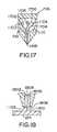
- FIG. 17is a cut-away view of the reader head assembly of FIG. 11 with first and second light emitting diodes, a photodetector, corresponding fiberoptic bundles and an aperture at a lower end thereof depicted;
- FIG. 18is a partial closeup cross-sectional view of a reader head tip of the reader head of FIG. 17 showing the aperture and ends of fiberoptic fibers of the fiberoptic bundles of FIG. 17 ;
- FIG. 19is a closeup bottom view of the aperture of the reader head of FIGS. 17 and 18 illustrating a sigmoidal pattern for positioning individual fiberoptic fibers (fiberoptic conductors);
- FIG. 20is a closeup end view of the corresponding fiberoptic bundle at the first light emitting diode of FIG. 17 from which the fiberoptic bundle conducts light from the first light emitting diode;
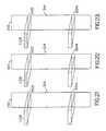
- FIG. 21is a schematic diagram illustrating a process by which an assay test strip is analyzed so as to determine an amount of background light at a control region of the assay test strip;
- FIG. 22is a schematic diagram illustrating a process by which an assay test strip is analyzed so as to determine an amount of reflection resulting from a first illumination of a control portion of the assay test strip;
- FIG. 23is a schematic view diagram illustrating a process by which an assay test strip is analyzed so as to determine an amount of reflection resulting from a second illumination of a control portion of the assay test strip;
- FIG. 24is a side view of an exemplary embodiment of the reader that is adapted for reading a bar code.
- FIG. 25is an example of a bar code in accordance with an exemplary embodiment of the assay device.
- point of care testingrefers to real time diagnostic testing that can be done in a rapid time frame so that the resulting test is performed faster than comparable tests that do not employ this system.
- the exemplified fFN immunoassayis performed in less time than the fFN ELISA assay (i.e., less than about 3 to 4 hours, preferably less than 1 hour, more preferably less than half an hour).
- itcan be performed rapidly and on site, such as in a doctor's office, at a bedside, in a stat laboratory, emergency room or other such locales, particularly where rapid and accurate results are required. The patient can be present, but such presence is not required.
- Point of careincludes, but is not limited to: emergency rooms, operating rooms, hospital laboratories and other clinical laboratories, doctor's offices, in the field, or in any situation in which a rapid and accurate result is desired.
- an anti-fFN antibodyis an antibody that binds selectively with fFN. Such antibodies are known to those of skill in the art and also may be readily isolated.
- a test striprefers to any means on which patient test data or other data is generated, recorded or displayed in a manner that forms an image or from which an image can be generated.
- Such stripsinclude, but are not limited to, immunochromatographic test strips, such as lateral flow devices, X-ray films, such as X-rays and films produced from sequencing gels, EKG printouts, MRI results and other such means that generate or from which an image as defined herein can be generated.
- the stripis preferably adapted for scanning or reading by a reader, preferably the reader provided herein. Although referred to as a “strip”, it can be of any shape or geometry, including rectangular, three dimensional, circular, and so forth.
- a sigmoidal pattern(also referred to herein as sigmoidal-like; see, e.g., FIG. 19 ) with reference to the fiberoptics refers to the S-shaped or snake-like pattern of illumination selected for maximizing illumination across the lines on the test strip.
- the patternis not strictly a sigmoidal shape, but refers to a pattern such as that depicted in FIG. 19 , which pattern provides a means for adding more area to any reading. Any other pattern that achieved this result is encompassed within this expression.
- fetal restricted antigensrefers to antigens that are present in pregnant women uniquely, or in substantially elevated amounts compared to non-pregnant women in maternal serum, plasma, urine, saliva, sweat, tears and other bodily fluids.
- fetal fibronectinis a fetal restricted antigen found in placenta, amniotic fluid and fetal connective tissue. It differs structurally from adult fibronectins. Fetal fibronectin is not present in significant quantities in maternal plasma or serum. Fetal fibronectin may be captured with a general binding antibody, such as an anti-fibronectin antibody, or an anti-fetal restricted antigen antibody, such as anti-fetal fibronectin antibody.
- an immunoassayis defined as any method using a preferential binding of an antigen with a second material, a binding partner, usually an antibody or another substance having an antigen binding site, which binds preferentially with an epitope of the fetal restricted antigen.
- Preferential bindingrefers to binding between binding partners that is selective and generally specific, and demonstrates less than 10%, preferably less than 5%, cross-reactive nonspecific binding.
- the immunoassay methods provided hereininclude any known to those of skill in the art, including, but not limited to, sandwich, competition, agglutination or precipitation, for example.
- a solid supportrefers to the material to which the antibody is linked.
- the support materialsinclude any material that can act as a support for attachment of the molecules of interest. Such materials are known to those of skill in this art.
- These materialsinclude, but are not limited to, organic or inorganic polymers, natural and synthetic polymers, including, but not limited to, agarose, cellulose, nitrocellulose, cellulose acetate, other cellulose derivatives, dextran, dextran-derivatives and dextran co-polymers, other polysaccharides, glass, silica gels, gelatin, polyvinyl pyrrolidone, rayon, nylon, polyethylene, polypropylene, polybutlyene, polycarbonate, polyesters, polyamides, vinyl polymers, polyvinylalcohols, polystyrene and polystyrene copolymers, polystyrene cross-linked with divinylbenzene or the like, acrylic resins, acrylates and acrylic acids, acrylamides, polyacrylamides, polyacrylamide blends, co-polymers of vinyl and acrylamide, methacrylates, methacrylate derivatives and co-polymers, other polymers and co-polymers with various functional
- a readerrefers to an instrument for detecting and/or quantitating data, such as on test strips.
- the datamay be visible to the naked eye but does not need to be visible.
- a reflectance readerrefers to an instrument adapted to read a test strip using reflected light, including fluorescence, or electromagnetic radiation of any wavelength. Reflectance can be detected using a photodetector or other detector, such as charge coupled diodes (CCD).
- CCDcharge coupled diodes
- a preferred reflectance readerwhich is provided and described herein, includes a cassette slot adapted to receive a test-strip, light-emitting diodes, optical fibers, a sensing head, including means for positioning the sensing head along the test strip, a control circuit to read the photodetector output and control the on and off operation of the light-emitting diodes, a memory circuit for storing raw and/or processed data, and a photodetector, such as a silicon photodiode detector.
- a sensing headrefers to the assembly which is adapted to read a test strip using reflected light or other electromagnetic radiation.
- the sensing head in the readerrefers to the part of the sensing head assembly that randomizes the optical bundles and arranges the fibers in the plane normal to the test strip.
- colorrefers to the relative energy distribution of electromagnetic radiation within the visible spectrum. Color can be assessed visually or by using equipment, such as a photosensitive detector.
- a color changerefers to a change in intensity or hue of color or may be the appearance of color where no color existed or the disappearance of color.
- a decision-support systemalso referred to as a “data mining system” or a “knowledge discovery in data system” is any system, typically a computer-based system, that can be trained on data to classify the input data and then subsequently used with new input data to make decisions based on the training data.
- data mining systemor a “knowledge discovery in data system”
- knowledge discovery in data systemis any system, typically a computer-based system, that can be trained on data to classify the input data and then subsequently used with new input data to make decisions based on the training data.
- These systemsinclude, but are not limited, expert systems, fuzzy logic, non-linear regression analysis, multivariate analysis, decision tree classifiers, Bayesian belief networks and, as exemplified herein, neural networks.
- an adaptive machine learning processrefers to any system whereby data are used to generate a predictive solution. Such processes include those effected by expert systems, neural networks, and fuzzy logic.
- an expert systemis a computer-based problem solving and decision-support system based on knowledge of its task and logical rules or procedures for using the knowledge.
- the knowledge and the logicare entered into the computer from the experience of human specialists in the area of expertise.
- a neural networkis a parallel computational model comprised of densely interconnected adaptive processing elements.
- the processing elementsare configured into an input layer, an output layer and at least one hidden layer.
- Suitable neural networksare known to those of skill in this art (see, e.g., U.S. Pat. Nos.
- a processing elementwhich may also be known as a perception or an artificial neuron, is a computational unit which maps input data from a plurality of inputs into a single binary output in accordance with a transfer function.
- Each processing elementhas an input weight corresponding to each input which is multiplied with the signal received at that input to produce a weighted input value.
- the processing elementsums the weighted inputs values of each of the inputs to generate a weighted sum which is then compared to the threshold defined by the transfer function.
- a transfer functionalso known as a threshold function or an activation function, is a mathematical function which creates a curve defining two distinct categories. Transfer functions may be linear, but, as used in neural networks, are more typically non-linear, including quadratic, polynomial, or sigmoid functions.
- an imageis a multi-dimensional array of data points, where each data point is represented by a number, or a set of numbers, and where there is a relationship between adjacent points in each of the dimensions.
- the index values in each dimensiontypically represent a linear relationship, like position or time, but are not limited to these types of relationships.
- a single digitized scan line from a TV framewould be considered a two dimensional image.
- an imagerefers to a one-dimensional set of pixels, which encode the intensity of the color on the test strip.
- classifying an imagerefers to associating an object or state with the image. Images of fruit might be classified as to the type of fruit shown in the image. In the case of the preferred embodiment, classifying the test strip image refers to associating the positive or negative state with the image.
- reconstructing an imagerefers to producing an image from a mathematical function.
- an imageis represented by a mathematical function, there may be errors in the representation due to any number of factors.
- backpropagationis a training method for neural networks for correcting errors between the target output and the actual output.
- the error signalis fed back through the processing layer of the neural network, causing changes in the weights of the processing elements to bring the actual output closer to the target output.
- diagnosisrefers to a predictive process in which the presence, absence, severity or course of treatment of a disease, disorder or other medical condition is assessed.
- diagnosiswill also include predictive processes for determining the outcome resulting from a treatment.
- riskrefers to a predictive process in which the probability of a particular outcome is assessed.
- a patient or subjectincludes any mammals for whom diagnosis is contemplated. Humans are the preferred subjects.
- biochemical test datarefers to data from any analytical methods, which include, but are not limited: immunoassays, bioassays, including nucleic acid and protein based assays, chromatography, data from monitors, and imagers; measurements and also includes data related to vital signs and body function, such as pulse rate, temperature, blood pressure, data generated by, for example, EKG, ECG and EEG, biorhythm monitors and other such information.
- the analysiscan assess for example, chemical analytes, serum markers, antibodies, protein, nucleic acids and other such material obtained from the patient through a sample.
- Immunoassaysare exemplified herein, but such exemplification is not intended to limit the intended scope of the disclosure, which is applicable to any test strip and test data read by an instrument, particularly a reflectance reader.
- patient historical datarefers to data obtained from a patient, such as by questionnaire format, but typically does not include biochemical test data as used herein, except to the extent such data is historical.
- a desired solutionis one that generates a number or result whereby a diagnosis of a disorder can be generated.
- a runis defined as a group of tests that include a at least one of a positive reference, positive control, negative control and any number of clinical samples within a 24 hr. period.
- symbologyrefers to a code, such as a bar code, that is engraved or imprinted on the test device.
- the symbologyis any code known or designed by the user.
- the symbolsare associated with information stored in a remote computer or memory or other such device or means.
- each test devicecan be uniquely identified with an encoded symbology. It is contemplated herein that identifying and other information can be encoded in the bar code, which can be read by the reader when the test strip is read. Alternatively, the bar code or other symbology may be read by any of reading devices known to those of skill in the art.
- a bar codeis a symbology, typically a field of alternating dark bars and reflective spaces of varying widths, that is affixed onto or associated with an item and provides identifying information about the item.
- Bar codescan be placed on a reflective background, and the contrast between the dark bars and reflective spaces, or the reflectivity ratio, allows an optical sensor in a reader to discern the transitions between the bars and spaces in the symbol.
- Bar codesare electro-optically scanned, typically using a laser or LED, and generate a signal that is transmitted to an associated computer whose memory has digitally stored therein identifying information associated with the item. The item is thereby automatically identified by its bar code and can be tracked, or additional information can be added to the stored information associated with the encoded item.
- bar code formatsare available and are used for different purposes.
- Preferred hereinare one-dimensional codes, such as the well known Code 39 and Code 128, although two-dimensional codes (see, e.g., U.S. Pat. Nos. 5,243,655 and 5,304,786, are also suitable for use herein.
- the 39 bar codewas developed in 1974 to provide a fully alphanumeric bar code for data entry systems. This bar code is especially effective in applications that use alphanumeric data for item identification.
- the structure of 39permits it to be printed by a wide variety of techniques, including offset, letterpress, fully-formed impact printers, dot matrix printers, and on-impact printing devices.
- Code 39is the most widely used alphanumeric bar code. It has been accepted as a standard code by many companies and industries. Specification ANSI Draft MH10.X-1981, entitled, “Specifications for Bar Code Symbols on Transport Packages & Unit Loads,” describes three different bar code symbologies. Code 39 is called 3-of-9 code in the ANSI specification. Moreover, the Depae MIL-STD-1189, dated Jan. 4, 1982, defines 39 (called 3 of 9 code) as the standard symbology for marking unit packs, outer containers, and selected documents.
- Code 39includes 9 bits, at least three of which are always 1.
- Code 39can be used to encode a set of 43 characters, including upper case alphabetic and numeric (0-9) characters, as well as seven special characters ( ⁇ , ⁇ , , *, $, /, + and %).
- the beginning and end charactersare always an asterisk (*).
- the codeuses narrow and wide bars along with narrow and wide spaces, and the encoding for a single character is made up of a pattern of bars and spaces.
- the code structureis three wide elements out of a total of nine elements, where an element is the area occupied by a bar or space). The nine elements include five bars and four spaces.
- Code 1208every character is constructed of eleven bars and spaces, and all 128 ASCII characters, i.e., numeric characters, upper and lower case characters, punctuation and control codes are encoded. There are three different character sets to select from: one set encodes all upper case characters and all ASCII control characters; another encodes all upper and lower case characters; and the third encodes all numeric characters. Through the use of special characters, it is possible to switch between character sets within a single code symbol.
- Code 128uses four different bar and space widths. Each data character encoded in a Code 128 symbol is made up of 11 black or white modules. Three bars and three spaces are formed out of the 11 modules. There are 106 different three bar/three space combinations. Bars and spaces can vary between one and four modules wide.
- the stop characteris made up of 13 modules.
- the symbolincludes a quiet zone (10 ⁇ -dimensions), a start character, the encoded data, a check character, the stop character and a trailing quiet zone (10 ⁇ -dimensions) (see, e.g., U.S. Pat. No. 5,262,625).
- the systemsare designed for use on site at the point of care, where patients are examined and tested, and for operation remote from the site.
- the systemsare designed to accept input in the form of patient data, including, but not limited to biochemical test data, physical test data, historical data and other such data, and to process and output information, preferably data relating to a medical diagnosis or a disease risk indicator.
- patient datamay be contained within the system, such as medical records or history, or may be input as a signal or image from a medical test or procedure, for example, immunoassay test data, blood pressure reading, ultrasound, X-ray or MRI, or introduced in any other form.
- Specific test datacan be digitized, processed and input into the medical diagnosis expert system, where it may be integrated with other patient information.
- the output from the systemis a disease risk index or medical diagnosis.
- the systemincludes a reader, such as a reflectance or transmission reader, preferably a reflectance reader, for reading patient data, a test device designed to be read in the reader, and software for analysis of the data.
- a readersuch as a reflectance or transmission reader, preferably a reflectance reader
- the readeris the reflectance reader provided herein.
- a test strip device in a plastic housing designed for use with the reader, optionally including a symbology, such as an alphanumeric character bar code or other machine-readable code, and software designed for analysis of the data generated from the test stripare also provided.
- any assayis intended for use in the systems and methods herein.
- Such assaysinclude, but are not limited to: nucleic acid detection, including using amplification and non-amplification protocols, and any assay that relies on colorimetric or spectrometric detection, including fluorometric, luminescent detection, such as creatine, hemoglobin, lipids, ionic assays, and blood chemistry.
- Any test that produces a signal, or from which a signal can be generated, that can be detected by a detector, such as a photodetector or a gamma counter,is intended for use as part of the systems provided herein. Any wavelength is intended to be included.
- Immunoassaysincluding competitive and non-competitive immunoassays, are among those preferred for determination of the presence or amount of analyte in a patient sample, and are exemplified herein. It is understood that immunoassays are provided for exemplification and that the methods and systems provided herein have broad applicability to patient test data and other test data.
- Immunoassaysmay be homogeneous, i.e. performed in a single phase, or heterogeneous, where antigen or antibody is linked to an insoluble solid support upon which the assay is performed. Sandwich or competitive assays may be performed. The reaction steps may be performed simultaneously or sequentially. Threshold assays may be performed, where a predetermined amount of analyte is removed from the sample using a capture reagent before the assay is performed, and only analyte levels of above the specified concentration are detected. Assay formats include, but are not limited to, for example, assays performed in test tubes, wells or on immunochromatographic test strips, as well as dipstick, lateral flow or migratory format immunoassays.
- Any known immunoassay procedureparticularly those that can be adapted for use in combination with lateral flow devices as described herein, can be used in the systems and methods provided herein.
- test stripsAny device which is compatible for use with a reader, preferably a reflectance reader, for determining the assay result is contemplated for use herein. Any such test strips that can be adapted for use in combination with a reader are contemplated for use in the systems provided herein.
- test strip devicesas are known to those of skill in the art (see, e.g., U.S. Pat. Nos. 5,658,801, 5,656,502, 5,591,645, 5,500,375, 5,252,459, 5,132,097 and many other examples) may be used in systems as described herein, particularly in combination with the reader provided herein.
- test devicesare intended for use with biological samples, such as saliva, blood, serum, cerebral spinal fluid, and cervicovaginal samples, for example.
- biological samplessuch as saliva, blood, serum, cerebral spinal fluid, and cervicovaginal samples
- Other biological samplessuch as food samples, which are tested for contamination, such as by bacteria or insects, are also contemplated.
- Target analytesinclude, but are not limited to: nucleic acids, proteins, peptides, such as human immunodeficiency virus (HIV) antigens, antigens indicative of bacteria, such as Salmonella and E.
- HIVhuman immunodeficiency virus
- colicoli, yeast or parasitic infections, apolipoprotein(a) and lipoprotein(a), environmental antigens, human chorionic gonadotropin (hCG), E-3-G, interleukins and other cytokines and immunomodulatory proteins, such as IL-6 and interferon, small nuclear ribonuclear particles (snRNP) antigens, fFN and other indicators, such as IGF binding protein-1, of pregnancy related disorders.
- hCGhuman chorionic gonadotropin
- E-3-Ginterleukins and other cytokines and immunomodulatory proteins, such as IL-6 and interferon
- IL-6 and interferoninterleukins and other cytokines and immunomodulatory proteins
- snRNPsmall nuclear ribonuclear particles
- fFNsmall nuclear ribonuclear particles
- a preferred embodimentis an immunoassay test strip that includes a membrane system that defines a liquid flow pathway.
- An exemplary immunoassay test strip provided hereinis shown in FIGS. 1A and 1B .
- the test stripis described in detail in EXAMPLE 1. This test strip is provided for purposes of exemplification of the methods and systems provided herein and is not intended to limit the application to immunoassay test strip devices.
- lateral flow test immunoassay devicesare among those preferred herein.
- a membrane systemforms a single fluid flow pathway along the test strip.
- the membrane systemincludes components that act as a solid support for immunoreactions.
- porous or bibulous or absorbent materialsmay be placed on a strip such that they partially overlap, or a single material can be used, in order to conduct liquid along the strip.
- the membrane materialsmay be supported on a backing, such as a plastic backing.
- the test stripincludes a glass fiber pad, a nitrocellulose strip and an absorbent cellulose paper strip supported on a plastic backing.
- Antibodies that react with the target analyte and/or a detectable label systemare immobilized on the solid support.
- the antibodiesmay be bound to the test strip by adsorption, ionic binding, van der Waals adsorption, electrostatic binding, or by covalent binding, by using a coupling agent, such as glutaraldehyde.
- the antibodiesmay be applied to the conjugate pad and nitrocellulose strip using standard dispensing methods, such as a syringe pump, air brush, ceramic piston pump or drop-on-demand dispenser.
- a volumetric ceramic piston pump dispenseris used to stripe antibodies that bind the analyte of interest, including a labeled antibody conjugate, onto a glass fiber conjugate pad and a nitrocellulose strip.
- the test stripmay or may not be otherwise treated, for example, with sugar to facilitate mobility along the test strip or with water-soluble non-immune animal proteins, such as albumins, including bovine (BSA), other animal proteins, water-soluble polyamino acids, or casein to block non-specific binding sites.
- water-soluble non-immune animal proteinssuch as albumins, including bovine (BSA), other animal proteins, water-soluble polyamino acids, or casein to block non-specific binding sites.
- the test stripoptionally may be contained within a housing for insertion into the reflectance reader.
- the housingmay be made of plastic or other inert material that does not interfere with the assay procedure.
- An exemplary assay device, including a test strip and housing assemblyis shown in FIGS. 2A-5 .
- the test strip housingincludes a symbology, such as a bar code that can be associated with data related to the assay device, patient data and/or test run.
- a symbologysuch as a bar code that can be associated with data related to the assay device, patient data and/or test run.
- information associated with the devicesuch as lot number, expiration date, analyte and intensity value, or information related to the test run, such as date, reflectance value or other such information, can be encoded and associated, such as in a database with a bar code imprinted on the device. Any bar code system that provides the appropriate line thickness and spacing can be used. Code 39 and Code 128 are among the preferred bar code systems.
- Code 39is used.
- An example bar codeis shown in FIG. 25 .
- the bar codeis made up of 11 alphanumerics, including 2 alphabetic and 9 numeric characters.
- the first and last charactersare asterisks (*), as is standard in the Code 39 system.
- the lot numberis stored as 1 alpha and 4 numeric codes so that product complaints or questions can be traced to a particular lot number.
- the first characterrepresents the month of production
- the secondis a digit representing the year of production
- the last threeare an index value indicating the lot number.
- the lot number “A8001”represents the first device in a lot produced in January, 1998.
- next two charactersrepresent the identity of the analyte as 2 numerics (00-99). This permits the use of up to 100 different analytes with the system.
- the reflectance intensity value(00-99) is stored as the next two numeric characters (“01”).
- the intensity valuesets the reference threshold for which controls and patient samples can be compared. This eliminates the need to run liquid reference samples on a daily basis.
- FIGS. 2A , 2 B, and 3depict assay devices that optionally include bar codes, 216 and 316 , respectively.
- the cassette expiration dateis stored as 1 alpha and 1 numeric code to prevent the use of expired devices. In the example given, an expiration code of “A9” represents an expiration date of January, 1999.
- any antibodyincluding polyclonal or monoclonal antibodies, or any fragment thereof, such as the Fab fragment, that binds the analyte of interest, is contemplated for use herein.
- Monoclonal and/or polyclonal antibodiesmay be used.
- a mouse monoclonal anti-fetal fibronectin antibodymay be used in a labeled antibody-conjugate for detecting fetal fibronectin
- a polyclonal goat anti-mouse antibodymay also be used to bind fetal fibronectin to form a sandwich complex.
- An antibody that binds to the labeled antibody conjugate that is not complexed with fetal fibronectinmay be immobilized on the test strip and used as a control antibody.
- a polyclonal goat anti-mouse IgG antibodymay be used.
- An antibody conjugate containing a detectable labelmay be used to bind the analyte of interest.
- the detectable label used in the antibody conjugatemay be any physical or chemical label capable of being detected on a solid support using a reader, preferably a reflectance reader, and capable of being used to distinguish the reagents to be detected from other compounds and materials in the assay.
- Suitable antibody labelsare well known to those of skill in the art.
- the labelsinclude, but are not limited to enzyme-substrate combinations that produce color upon reaction, colored particles, such as latex particles, colloidal metal or metal or carbon sol labels, fluorescent labels, and liposome or polymer sacs, which are detected due to aggregation of the label.
- a preferred labelis a colored latex particle.
- colloidal goldis used in the labeled antibody conjugate.
- the labelmay be derivatized for linking antibodies, such as by attaching functional groups, such as carboxyl groups to the surface of a particle to permit covalent attachment of antibodies.
- Antibodiesmay be conjugated to the label using well known coupling methods. Coupling agents such as glutaraldehyde or carbodiimide may be used.
- the labelsmay be bonded or coupled to the antibodies by chemical or physical bonding.
- a carbodiimide coupling reagent, 1-ethyl-3-(3-dimethylaminopropyl)carbodiimide (EDAC)is used to link antibodies to latex particles.
- any analyte that can be detected in any assay, particularly colorimetric assays, including immunoassays, and that can be associated with a disorderis contemplated for use as a target herein.
- Suitable analytesare any which can be used, along with a specific binding partner, such as an antibody, or a competitor, such as an analog, in an assay.
- Analytesmay include, but are not limited to proteins, haptens, immunoglobulins, enzymes, hormones (e.g., hCG, LH, E-3-G estrone-3-glucuronide and P-3-G (progestrone-3-glucuronide)), polynucleotides, steroids, lipoproteins, drugs, bacterial or viral antigens, such as Streptococcus, Neisseria and Chlamydia, lymphokines, cytokines, and the like.
- hormonese.g., hCG, LH, E-3-G estrone-3-glucuronide and P-3-G (progestrone-3-glucuronide)
- polynucleotidese.g., steroids, lipoproteins, drugs, bacterial or viral antigens, such as Streptococcus, Neisseria and Chlamydia, lymphokines, cytokines, and the like.
- suitable analytesare described
- fetal fibronectinin cervicovaginal samples, the systems and methods provided herein are not limited to the detection and measurement of fetal fibronectin, but apply to any biochemical test, particularly those for which test strips can be developed or for which test strips are known.
- the systemis used for diagnosing or predicting conditions such as pregnancy, including ectopic pregnancy, pre-eclampsia, preterm labor or imminent delivery and fetal membrane rupture.
- Fetal fibronectinis a fetal restricted antigen found in placenta, amniotic fluid and fetal connective tissue. Since fetal fibronectin is strictly associated with pregnancy, determination of the presence of fetal fibronectin in a cervicovaginal sample is a highly reliable early indication of pregnancy. Also, the absence of a fetal restricted antigen in a cervicovaginal sample during the first 20 weeks of pregnancy is an indicator of ectopic pregnancy.
- Ectopic pregnancieswhich are a major cause of morality for women, are not readily distinguished from normal pregnancies using standard pregnancy determination methods and tests. Determination of impending preterm births is critical for increasing neonatal survival of preterm infants.
- the presence of fetal fibronectin (fFN) in cervicovaginal secretion samples in patients after week 12 of pregnancyis associated with a risk of impending delivery, including spontaneous abortions (12-20 weeks), preterm delivery (20-37 weeks), term (37-40 weeks) and post-date delivery (after 40 weeks), in pregnant women.
- fetal fibronectin in a cervicovaginal sampleprovides a method for determining increased risk of labor and fetal membrane rupture after week 20 of pregnancy.
- Detection of rupture of the amniotic membraneis important in distinguishing true and false labor, and when the rupture is small and the volume of amniotic liquid escaping is small, the rupture is often undetected.
- the methods and systems hereinprovide a means to reliably assess the risk for any of these conditions.
- An immunoassay procedure for detecting fetal fibronectinis described in EXAMPLE 2.
- An antibody that will bind the analyte of interestis conjugated to a detectable label.
- a mouse monoclonal anti-fFN antibody(see, U.S. Pat. No. 5,281,522), conjugated to latex particles containing a blue dye may be used.
- a goat polyclonal antibody to human fibronectinis conjugated to a colloidal gold label.
- an antibody that binds the labeled antibody conjugate that is not complexed with fetal fibronectinis used as a control antibody.
- the labeled conjugateincludes a monoclonal anti-fetal fibronectin antibody
- a polyclonal goat anti-mouse IgG antibodyis used.
- the antibodiesmay be raised and purified using methods known to those of skill in the art or obtained from publicly available sources.
- monoclonal antibody FDC-6deposited at the American Type Culture Collection as accession number ATCC HB 9018; see U.S. Pat. No. 4,894,326; see, also, Matsuura et al. (1985) Proc. Natl. Acad. Sci. U.S.A. 82:6517-6521; see, also, U.S. Pat. Nos.
- a patient sampleis obtained.
- the samplemay include fluid and particulate solids, and, thus, can be filtered prior to application to the assay test strip.
- the samplemay be removed from the patient using a swab having a fibrous tip, an aspirator, suction or lavage device, syringe, or any other known method of removing a bodily sample, including passive methods for collecting urine or saliva.
- the samplemay be extracted into a buffer solution, and optionally heated, for example, at 37° C. and filtered.
- the sampleis obtained from in the vicinity of the posterior fornix, the ectocervix or external cervical os using a swab having a dacron or other fibrous tip.
- a volume of the test sampleis then delivered to the test strip ( FIGS. 1A and 1B ) using any known means for transporting a biological sample, for example, a standard plastic pipet.
- a biological samplefor example, a standard plastic pipet.
- Any analyte in the samplebinds to the labeled antibody, and the resulting complex migrates along the test strip.
- the samplemay be pre-mixed with the labeled conjugate prior to applying the mixture to the test strip.
- the immobilized antibody thereinbinds the complex to form a sandwich complex, thereby forming a colored stripe.
- Any unbound latex-conjugated antibodycontinues to migrate into a control zone where it is captured by a second immobilized antibody or other agent capable of binding the conjugate, and thereby forms a second colored stripe due to the aggregation of the dye-containing latex beads. This indicates that the assay run has been completed.
- the results of the assayare assessed using the reader and software provided herein.
- the rapid test hereinprovides, at the very least, the same clinically relevant information as a fFN ELISA (an enzyme linked immunosorbent sandwich assay (ELISA) see, e.g., U.S. Pat. No. 5,281,522) test heretofore available, but in significantly less time and at the point of care.
- a fFN ELISAan enzyme linked immunosorbent sandwich assay (ELISA) see, e.g., U.S. Pat. No. 5,281,522
- This rapid fFN immunoassayallows the user to test a cervicovaginal swab sample in about 20 minutes.
- images and digitize imagessuch as symbologies, particularly bar codes or the lines and stripes produced on chromatographic immunoassay devices or on gels or photographic images thereof, such as the lines on DNA and RNA sequencing gels, X-rays, electrocardiograms, and other such data, is intended for use herein.
- a sampleis applied to a diagnostic immunoassay test strip, and colored or dark bands are produced.
- the intensity of the color reflected by the colored label in the test region (or detection zone) of the test stripis, for concentration ranges of interest, directly proportional or otherwise correlated with an amount of analyte present in the sample being tested.
- the color intensity producedis read, in accordance with the present embodiment, using a reader device, for example, a reflectance reader, adapted to read the test strip.
- the intensity of the color reflected by the colored label in the test region (or detection zone) of the test stripis directly proportional to the amount of analyte present in the sample being tested. In other words, a darker colored line in the test region indicates a greater amount of analyte, whereas a lighter colored line in the test region indicates a smaller amount of analyte.
- the color intensity producedi.e., the darkness or lightness of the colored line, is read using a reader device, for example, a reflectance reader, adapted to read the test strip.
- a reflectance measurement obtained by the reader deviceis, in accordance with the present embodiment, correlated to the presence and/or quantity of analyte present in the sample as described hereinbelow.
- the readertakes a plurality of readings along the strip and obtains data that are used to generate results that are an indication of the presence and/or quantity of analyte present in the sample as described hereinbelow.
- the systemalso correlates such data with the presence of a disorder, condition or risk thereof.
- the readermay be adapted to read a symbology, such as a bar code, which is present on the test strip or housing and encodes information relating to the test strip device and/or test result and/or patient and/or reagent or other desired information.
- a symbologysuch as a bar code
- the associated informationis stored in a remote computer database, but can be manually stored.
- the symbologycan be imprinted when the device is used and the information encoded therein.
- an exemplary embodiment of the reader device 600is shown with an immunoassay device 200 , as shown in FIG. 2A , inserted into a cassette slot 602 therein.
- the cassette slot 602is adapted to receive the immunoassay device 200
- a reader head assembly(not shown) supported within the reader device 600 is adapted to read the immunoassay test strip, and optionally a symbology, exemplified as a bar code, on the immunoassay device.
- Such readingis performed by scanning a reader head (not shown) across the device, including a test window 214 in the immunoassay device 200 and a symbology, such as the exemplified bar code 216 , if present, and in the process directing light onto the bar code and/or a test portion and a control portion of the immunoassay test strip. An amount of such light reflected back from the bar code and/or the test portion and control portion of the immunoassay test strip is measured as the reader head scans across the device.
- a data entry keypad 604including ten digit keys (also labeled with letters of the alphabet, such as is commonly the case on telephone keypads), a delete key, a space key, an escape key, a print key, enter key, and up, down, left and right arrow keys, additional characters such as, or . or /, and any other desired by the user.
- the data entry keypad 604can be used by an operator of the reader device 600 to input identification information, to enter control test parameters, to initiate and terminate testing, and the like.
- a processing unithoused within the reader device 600 is responsive to the keypad and performs data analysis functions, as described hereinbelow, in accordance with modifications made to a processor in the processing unit by an appropriate software subsystem.
- the liquid crystal display screen 606receives output data from the processing unit and displays it to an operator of the reader device 600 , including displaying results of tests, error messages, instructions, troubleshooting information, and the like.
- FIG. 7a perspective view of a lower housing 702 of one embodiment of an immunoassay reader device 600 of FIG. 6 is shown with a reader head assembly 704 located therein and the immunoassay device 200 inserted into the cassette slot 602 at a front edge of the lower housing 702 .
- the cassette slot 602 located at the front edge of the lower housing 702provides an aperture through which the immunoassay device 200 is inserted into and guided into the reader device 600 in order measure light reflected from an immunoassay test strip.
- the readeris adapted to additionally read a symbology, such as a bar code, imprinted, engraved on or otherwise affixed to the test strip or device.
- a reader head 706 on the reader head assembly 704is positioned directly above the device 200 , such that the longitudinal (or major) axes of optical fibers within the reader head 706 are normal to a surface of the device, including the test strip and optionally a symbology that is imprinted, engraved or other wise affixed on the device.
- the reader head 706may be fixed, at least rotationally, and the immunoassay device 200 may be moved into position after insertion into the cassette slot 602 , such that the longitudinal (or major) axes of optical fibers within the reader head 706 are normal to a surface of the device to be read by the reader.
- FIG. 8a top view is shown of the lower housing 702 , the immunoassay device 200 , the cassette slot 602 , and a stepper motor 802 .
- the immunoassay device 200is positioned in alignment with the stepper motor 802 , which is part of the reader head assembly.
- the stepper motoris used to scan the reader head 706 across the symbology, such as the exemplified bar code 216 and/or test window 214 of the immunoassay device 200 .
- FIG. 9Shown are the lower housing 702 , the immunoassay device 200 , the stepper motor 802 , an actuator wheel 902 , the reader head 706 , and linkages for moving the reader head 706 parallel to a major axis of the immunoassay device 200 in order to scan the reader head 706 across the symbology (bar code) 216 and/or test window 214 of the immunoassay device 200 .
- the reader headis brought within a uniform distance of about 0.010 inches from the test strip.
- the actuator wheel 902 and an actuator spring(not shown) work together to bring the reader head 706 down to within about 0.010 inches of the immunoassay test strip within the housing 202 of the immunoassay device 200 .
- the reader head 706is pivoted along with a portion of the reader head assembly.
- the reader head 706Prior to being brought into position within 0.010 inches of the immunoassay test strip, while the immunoassay device 200 is being inserted into or removed from the immunoassay reader device 600 , the reader head 706 assumes a retracted position, i.e., raised position, so that the immunoassay device 200 can be inserted into or removed from the immunoassay reader device 600 without crashing the reader head 706 into the immunoassay device 200 .
- the immunoassay device 200When the immunoassay device 200 is inserted into the cassette slot 602 , it contacts the actuator wheel 902 and causes a carriage assembly of the reader head assembly to be brought down from the retracted position so that the reader head 706 is within 0.010 inches of the immunoassay test strip.
- Insertion of the immunoassay device 200causes the actuator wheel to pop-up by applying pressure to the actuator spring, bringing the carriage assembly down from the retracted position.
- the immunoassay device 200is pushed into the cassette slot 602 until it meets a stop. Once inserted, the immunoassay device 200 , the actuator wheel 902 , and the actuator spring remain fixed in position, while the reader head 706 is stepped across the test window 214 of the immunoassay device 200 by the stepper motor 802 . In other words, only the reader head 706 moves during the scanning of the immunoassay test strip.
- the immunoassay device 200is pushed into the cassette slot 602 until it meets the stop. Once inserted the immunoassay device 200 may be rotated up to within 0.010 inches of the reader head 706 by gently lifting the immunoassay device 200 . By gently lifting the immunoassay device 200 , a base of the reader head assembly is pivoted up toward the carriage assembly and the reader head 706 , positioning the immunoassay test strip within 0.010 inches of the reader head 706 . The reader head 706 is then stepped across the test window 214 of the immunoassay test strip by the stepper motor 802 . In other words, in accordance with this alternative, only the reader head 706 moves during the scanning of the immunoassay test strip, and, the reader head 706 moves only during the scanning of the immunoassay test strip.
- the reader head 706Prior to insertion of the immunoassay device 200 into the cassette slot 602 , and prior to scanning, the reader head 706 is positioned at a point that would place it approximately half way across (in the middle of) the test window 214 of the immunoassay device 200 .
- the reader head 706After insertion of the device 200 into the reader 600 , when an operator depresses a scan key on the key pad (see FIG. 6 ), the reader head 706 is moved from this position toward the stepper motor 802 until a microswitch is activated. Once the microswitch is activated, the reader head 706 is said to be in a “home” position from which scanning of the test strip commences. Once scanning commences, the reader head 706 advances from the home position across the test window 214 .
- the reader head 706scans in a direction moving away from the stepper motor toward the cassette slot 602 or to the left as depicted in FIG. 9 .
- Total travel of the reader head 706 during scanning of the immunoassay test stripis 0.452 inches, which is achieved in 0.002 inch steps, which are 226 in number.
- One set of readingsis taken per step, with each set of readings including a dark reading, a first light reading and a second light reading.
- the reader head assembly 1000is shown. Shown are the actuator spring 1002 , the actuator 1004 , the base 1006 , the stepper motor 802 , the actuator wheel 902 , a rotor arm 1008 , and the reader head 706 . Also shown is a pivot point 1010 on which the carriage assembly 1012 , including the reader head 706 , stepper motor 802 , actuator wheel 902 , actuator spring 1002 , and rotor arm 1008 pivot to assume a raised position for insertion and removal of the immunoassay device 200 from the reader device 600 and to assume a lowered position for scanning the reader head 706 across the test window 214 of the immunoassay device 200 .
- FIG. 11shown is a side view of the reader head 706 of the reader head assembly of FIG. 10 . Shown is a first light emitting diode (LED) 1102 , a second light emitting diode (LED) 1104 , a photodetector 1106 , a reader head aperture 1108 , and mounting holes 1110 .
- LEDlight emitting diode
- LEDsecond light emitting diode
- FIG. 12a reverse angle side view is shown of the reader head assembly 1000 of FIG. 10 . Shown are the stepper motor 802 , the base 1006 , mounting holes 1202 , and a mounting bracket 1204 on which the reader head 706 is mounted.
- FIG. 13a reverse angle side view of the reader head 706 of FIG. 11 is shown. Seen are the mounting holes 1110 , and the reader head aperture 1108 .
- FIG. 14shown is a side view of the reader head assembly 1000 of FIG. 10 having assumed a retracted position. Shown are the actuator spring 1002 , the actuator arm 1004 , the stepper motor 802 , the reader head 706 , the reader head supporting bracket 1204 , the pivot 1010 on which such elements rotate, and a base 1006 relative to which such elements rotate.
- the actuator arm 1004 , the actuator spring 1002 , the stepper motor 802 , the reader head 706 , the reader head mounting bracket 1204 , and mechanisms used for supporting and scanning the reader head 706are designed so that the test strip 100 in the device 200 is positioned within 0.010 inches of the aperture 1108 of the reader head. Any design suitable to effect such can be employed with the present embodiment.
- the actuator arm 1004 , the actuator spring 1002 , the stepper motor 802 , the reader head 706 , the reader head mounting bracket 1204 , and the mechanisms used for supporting and scanning the reader head 706are shown rotated on the pivot 1010 such as would be the case, in accordance with the variation shown, when the immunoassay device 200 has been removed from the reader device 600 and/or as the immunoassay device 200 is being inserted into or removed from the reader device 600 .
- FIG. 15a side view is shown of the reader head 706 of FIG. 11 . Shown are the aperture 1108 and the first light emitting diode 1102 .
- FIG. 16an end view is shown of the reader head assembly 1000 of FIG. 10 . Shown is the stepper motor 802 , the base 1006 , and the actuator arm 1004 .
- the readeris adapted to read a symbology, such as a bar code.
- a symbologysuch as a bar code.
- FIG. 24An exemplary embodiment of a reader so-adapted is shown in FIG. 24 .
- the reader head 2406Prior to insertion of the device 300 (as shown in FIG. 2B ) into the cassette slot 602 , and prior to scanning, the reader head 2406 is positioned at a point that would place it approximately 0.125 inches from the forward edge of the device as it is inserted into the reader.
- the deviceincludes guide ridges 318 on either side of the bar code along the outer edges of the upper surface of the device.
- the reader head 2406is moved by the shaft 2408 of the stepper motor 2414 and scans in a direction moving away from the stepper motor toward the cassette slot 2412 .
- the guide ridges 2412contact the reader head assembly and act to compress the spring stage 2404 by 3° in order maintain the reader head 2406 at a distance of 0.010 inches above the bar code 2410 as the bar code 2410 is read.
- the reader head assembly 2406moves off the guide ridges 2412 , the spring stage 2404 returns to a level position (0°), and the reader head 2406 is repositioned at a distance of 0.010 inches in order to read the test strip.
- the readeris moved in steps of approximately between 0.002-0.008 inches at a scan resolution of approximately 125-500 steps per inch, preferably about 250 steps per inch.
- One set of readingsis taken per step, with each set of readings including a dark reading, a first light reading and a second light reading.
- a suitable mechanismis preferably employed to effect such positioning.
- FIG. 17shown is a side view partially in cross-section of an exemplary embodiment of the reader head. Shown are a first light emitting diode 1102 , a second light emitting diode 1104 and a photodetector 1106 . Also shown is an aperture 1108 and the mounting holes 1110 . Shown coupled between each of the LED's 1102 , 1104 and the aperture 1108 are first and second fiberoptic bundles 1702 , 1704 . Similarly, a third fiberoptic bundle 1706 is shown coupled between the aperture 1108 and the photodetector 1106 .
- the first and second fiberoptic bundles 1702 , 1704conduct light from the first and second LED's 1102 , 1104 , respectively, to the aperture 1108 .
- the third fiberoptic bundle 1706conducts light from the aperture 1108 to the photodetector 1106 .
- the photodetectorIn response to such light, the photodetector generates a reflection signal, e.g., a voltage indicative of an amount of reflected light.
- the electrical signalcan be then processed and converted to a digital signal by using any method commonly known to those of skill in the art.
- FIG. 18shown is a closeup partial cross-sectional view of the aperture 1108 of FIG. 17 . Also shown are individual fiberoptic fibers 1802 , 1804 , 1806 of the fiberoptic bundles 1702 , 1704 , 1706 of FIG. 17 , positioned within the aperture 1108 so as to transmit light 1108 from the aperture 1108 onto the symbology (exemplified bar code) and/or test strip 100 and to receive reflected light 1808 from the bar code and/or test strip 100 entering the aperture 1108 . (The transmitted and reflected light 1808 is represented with an arrow.) As can be seen, a gap 1810 between the aperture 1808 and the bar code and/or test strip 100 is present. The gap 1810 preferably has a width of approximately 0.010 inches, which is maintained as the reader head 706 is scanned across the bar code and/or test window 214 of the test strip 100 .
- FIG. 19a bottom view is shown of individual fiberoptic fiber ends 1902 , 1904 , 1906 positioned in the aperture 1108 of the reader head 706 of FIG. 10 so as to maximize the distribution of light emitted from individual fiberoptic fibers (fiberoptic conductors), and furthermore to maximize the uniformity of light received into individual fiberoptic conductors.
- Individual fiberoptic conductor ends 1902 of the first fiberoptic bundle 1702are individual fiberoptic conductor ends 1902 of the first fiberoptic bundle 1702 .
- These individual fiberoptic conductor ends 1902carry light emitted from the first light emitting diode from the first fiberoptic bundle through the aperture 1108 of the reader head 706 .
- fiberoptic conductor ends 1904 of the second fiberoptic bundle 1704are fiberoptic conductor ends 1904 of the second fiberoptic bundle 1704 . These individual fiberoptic conductor ends carry light emitted from the second light emitting diode to the aperture 1108 of the reader head 706 . Without cross-hatching are shown individual fiberoptic conductor ends 1906 of the third fiberoptic bundle 1706 . The third fiberoptic bundle 1706 carries light entering the aperture 1108 to the photodetector.
- the fiberoptic conductor ends 1902 , 1904 , 1906By employing the particularly advantageous arrangement of the fiberoptic conductor ends 1902 , 1904 , 1906 at the aperture 1108 , uniform distribution emissions and light reception is achieved. Such arrangement is said to be a “sigmoidal” (S-like or serpentine) arrangement or a “sigmoidal” distribution. It is an important feature of the present embodiment that the fiberoptic fibers in each of the three groups are arranged along with fiberoptic fibers from the remaining groups in a sigmoidal-like (or “S”-like) pattern with three columns of thirteen fiberoptic fibers each. An arrangement that achieves this feature is intended herein.
- 39 fiberoptic conductorsare positioned within the aperture 1108 .
- a clamp assemblymade up of a “U”-shaped channel, and an “I”-shaped clamp positioned at the open side of the “U” is employed.
- the fiberoptic conductors, portions of which protrude from the aperture 1108are placed between the “U”-shaped channel and the “I”-shaped clamp, and a compressive force is applied thereto by the “I”-shaped clamp, holding the protruding portions of the fiberoptic conductors firmly in position.
- a resinis then poured into the reader head 706 so as to become interposed between and around the fiberoptic conductors at the aperture 1108 .
- the clamp assemblyis removed, and the protruding portions of the fiberoptic conductors are trimmed back flush with the aperture 1108 , so as to define a planar surface of fiberoptic conductor ends 1902 , 1904 , 1906 at the aperture 1108 .
- This planar surfaceis held parallel to a plane at an upper surface of the immunoassay test strip 100 during scanning of the immunoassay test strip.
- the associated fiberoptic conductorshave longitudinal axes that are substantially parallel to one another and normal to the plane defined by the fiberoptic conductor ends 1902 , 1904 , 1906 .
- very efficient transfer of light to and from the fiberoptic conductor ends 1902 , 1904 , 1906is achieved.
- the individual fiberoptic conductorsare tested by projecting light individually through the fiberoptic conductors toward the fiberoptic conductor ends 1902 , 1904 , 1906 , to locate the fiberoptic conductor end associated with the particular fiberoptic conductor being tested. This determination is made by observing which of the fiberoptic conductor ends 1902 , 1904 , 1906 “lights up” when light is transmitted down the particular fiberoptic conductor.
- the fiberoptic conductorsare assigned to one of the first, second, and third fiberoptic bundles, so as to achieve, for example, the sigmoidal distribution of fiberoptic conductor ends 1902 , 1904 , 1906 illustrated in FIG. 19 .
- FIG. 20a cross-sectional view of a first fiberoptic bundle 1702 is shown with individual fiberoptic elements 2002 selected to effect the sigmoidal distribution of FIG. 19 .
- 13 individual fiberoptic elementsare present in the fiberoptic bundle 1702 , which is the same number of fiberoptic conductor ends 1902 , 1904 , 1906 depicted in FIG. 19 for each of the three fiberoptic bundles 1702 , 1704 , 1706 .
- the fiberoptic bundle 1702 shown in FIG. 17carries the light from the first light emitting diode to the aperture 1108 of the reader head 706 .
- Cross-sectional views of the second and third fiberoptic bundlesare similar to that shown in FIG. 20 .
- FIGS. 21 , 22 and 23three schematic views are shown illustrating a process for reading test results from immunoassay test strip 100 with the control region 2102 and the detection region 2104 depicted thereon.
- blue latex particlesare detected in the test region and the control region on a nitrocellulose support.
- the aperture 1108 of the reader head 706in a dark reading mode (FIG. 21 ), a first light reading mode ( FIG. 22 ) and a second light reading mode (FIG. 23 ).
- the reader head assemblyincludes the first light-emitting diode (which in the present example is a blue LED), the second LED (which in the present example is an amber LED), a silicon photodiode detector, and fiberoptic fibers arranged with fiberoptic conductor ends 1902 , 1904 , 1906 in the sigmoidal distribution in the aperture 1108 (e.g., 0.002 inches wide), which is located at the bottom (or tip) of the reader head 706 at a point nearest the immunoassay test strip, when the immunoassay device is inserted into the immunoassay reader device.
- the selection of LEDswill be dependent upon the signal produced in the test; all detectable electromagnetic wavelengths, preferably visible light, are contemplated herein. Fluorescence and other such labeling means are also contemplated herein.
- the blue LED and the amber LEDemit light of specified wavelengths ( ⁇ 1 and ⁇ 2 , respectively). It should be understood that any suitable wavelengths may be selected. Such selection is dependent on the particular assay with which the immunoassay reader device is being employed. The wavelengths selected are selected so as to allow removal of effects of the background of the immunoassay test strip or symbology, e.g., bar code, from the reflectance readings, and to optimize a reading of a reduction in reflectance associated with accumulated label at the reaction regions of the immunoassay test strip.
- the first light emitting diode (LED 1 )i.e., the blue LED
- the same wavelengthscan be used to read a symbology, such as a bar code, associated with the assay device.
- the first fiberoptic bundle 1702transmits blue light to the aperture 1108 in the reader head 706 where it is emitted at an orientation normal to a plane at the upper surface of the symbology (exemplified bar code) or test strip.
- the second fiberoptic bundle 1704transmits the amber light to the aperture in the reader head 706 where it is emitted at an orientation normal to the plane at the upper surface of the bar code or test strip.
- individual fiberoptic conductor ends 1902 , 1904 of the first and second fiberoptic bundles 1702 , 1704 , along with individual fiberoptic conductor ends 1906 from the third fiberoptic bundle 1706are arranged in three groups of thirteen optical fibers each: the first group from the first fiberoptic bundle 1702 , which transmits light emitted by the blue LED to the aperture 1108 ; the second group from the second fiberoptic bundle 1704 , which transmits light emitted by the amber LED to the aperture 1108 ; and the third group, which transmits reflected light received at the aperture 1108 through the third fiberoptic bundle 1706 to the photodetector.
- the thirty-nine fiberseach include respective fiberoptic conductor ends 1902 , 1904 , 1906 arranged in the sigmoidal distribution (or pattern) (see FIG. 19 ) at the aperture 1108 such that the fiberoptic conductor ends 1902 , 1904 , 1906 are co-planar at the aperture and in the plane parallel to the plane at the upper surface of the bar code or test strip, when the reader head 706 is positioned to take measurements from the bar code or test strip 100 .
- each fiberoptic fiber(or conductor) has a longitudinal axis that is normal to the plane at the upper surface of the bar code or test strip. As a result, light emitted from the fiberoptic conductor ends 1902 and 1904 is directed in a direction substantially normal to this surface plane.
- the fiberoptic fibers in each of the three groupsare arranged along with fiberoptic fibers from the remaining groups in a sigmoidal (or “S”-like) pattern with three columns of thirteen fibers each.
- the reader head 706is positioned directly over the bar code or test opening of the assay device such that the longitudinal axes of the optical fibers at their ends 1902 , 1904 , 1906 at the aperture, are normal to a plane at the surface of the immunoassay test strip and the ends 1902 , 1904 , 1906 of the fibers at a distance of about 0.010 inches.
- Light from the first LED and the second LEDis transmitted by the fibers onto the bar code or assay test strip at an angle normal to the upper surface of the immunoassay device, and light is reflected normally back from the strip to the ends 1902 , 1904 , 1906 . This reflected light is transmitted by the fibers of the third fiberoptic bundle to the photodetector.
- the reader head 706takes three separate reflectance readings ( FIGS. 21 , 22 and 23 , respectively) from each position at which it reads of the immunoassay test strip. Such measurements are made by reading an output of the photodetector (which is a voltage) while controlling the first and second LED's.
- the first readingis used to determine an amount of ambient (or background) light leaking into the immunoassay device (e.g., light leaking through the cassette slot entrance, or light reflected/transmitted into the reader through the housing of the immunoassay device, which may be, for example, white plastic).
- the first readingis a “dark” reading taken with the blue LED and the amber LED both turned off.
- This dark reading(which is a voltage at the photodetector) is digitized in a conventional manner using an analog to digital converter, and may be subtracted by the processing unit from other “light” readings made in response to blue LED illumination and amber LED illumination so as to correct for this light leakage.
- the second readingused to determine levels of light reflections associated with the background of the bar code or the assay test strip itself, is taken with the blue LED pulsed on and the amber LED turned off.
- the third reading, used to detect the bar code or the presence of the label on the assay test stripis taken with the amber LED pulsed on and the blue LED turned off.
- a control circuit(including the processing unit, which includes a processor, such as a microprocessor) receives the digitized output of the photodetector for all three readings, controls the on and off operation of the blue LED and the amber LED, controls when photodetection readings are taken, and controls the position of the reader head 706 by controlling the stepper motor.
- a memory circuitstores raw and/or processed data (i.e., readings from the photodetector). The data may also be displayed to the operator via the LCD display of the immunoassay reader device 600 .
- the reader head 706After being positioned above the housing, the reader head 706 is moved (scanned) across the bar code and/or test strip by the stepper motor under the control of the control circuit to allow the reader head 706 to scan the exposed surface of the bar code and/or assay test strip (including the detection and control zones through the test window 214 in the immunoassay device).
- the distance between reader head 706 and the bar code or assay test strip 100is approximately 0.010′′.
- the reader head 706is slidably connected to a rail (e.g., guide rods), and is coupled to a worm or screw gear driven by the stepper motor.
- a raile.g., guide rods
- the stepper motordrives the reader head 706 along the rail in small steps.
- the control circuittakes the three readings described above (“dark”, blue LED illuminated, amber LED illuminated).
- the control circuitmoves the reader head 706 such that the fiberoptic conductor ends 1902 , 1904 , 1906 pass directly above and normal to the exposed surface of the bar code and/or test strip in a sequence of small steps.
- a sequence of “dark”, blue LED and amber LED readingsare taken and recorded.
- the raw data read from the photodetectoris then processed by the control circuit to discern the symbology, such as a bar code pattern, in order to provide information regarding the assay device and/or test run and/or reagents, and/or patient and/or other desired information to read the test strip to determine the presence or concentration of analyte in the sample.
- symbologysuch as a bar code pattern
- the detection and control latex stripesare each about 0.020′′ wide, and since each step of the sensing head is about 0.002′′ long, there will be about 10 steps within each stripe, i.e., within the test region and the control region.
- there will be 10 sets of three readingsi.e., dark, blue LED and amber LED
- 10 sets of three readingsi.e., dark, blue LED and amber LED
- the remainder of the reading setswill not be made over either the test region or the control region.
- the reader head 706when the assay device is inserted into the cassette slot of the reader device 600 , the reader head 706 is positioned over the bar code or test strip, and the control circuit then moves the head to an initial (or home) position.
- the control circuitmoves (scans) the head across the exposed surface of the bar code or test strip, including the test region and the control region of the strip, in small increments.
- the control circuittakes the first reading ( FIG. 21 ) of the photodetector output with the blue LED and the amber LED, both off, takes the second reading ( FIG. 22 ) with the blue LED pulsed on and the amber LED off, and takes the third reading ( FIG. 23 ) with the blue LED off and the amber LED pulsed on.
- the control circuitthen steps the reader head 706 by controlling the stepper motor and repeats the three readings at its new location. For the test strip, this process is repeated for each of 226 steps (0.452′′ at 0.002′′/step) until the surface of the assay test strip is read.
- the length of the bar codeis typically approximately 1 inch in length, and a step size of approximately 0.002-0.008 inch is used; thus between approximately 125-500 steps are performed.
- the raw reflectance dataare then analyzed by the control circuit in accordance with appropriate software control to identify the symbology, such a bar code or determine the presence or concentration of the analyte in the sample.
- the readeris used to read a bar code associated with the test device
- the data collected from the bar codeare transformed into integrated peak information and analyzed as alphanumeric characters to provide information about the assay device and/or test run.
- the readeris used to detect an analyte
- the data collected from the test stripare compared to a threshold or reference reflectance value to determine the presence or concentration of the analyte.
- the outputcan be displayed via an operator interface, or can be output to another computer or apparatus.
- the systems hereininclude software for data analysis.
- Data analysisincludes any algorithms or methodology for obtaining diagnostically relevant information from the raw data. Simple algorithms as well as decision-support systems, particularly neural networks are contemplated herein.
- the data analysis methodologyincludes, some or all of the following steps: (1) optionally correcting the reflectance readings to correct for light leakage; (2) reducing the raw reflectance data by using a ratiometric formula; (3) generating an image of the test data by plotting the reduced data; (4) expressing this image as a polynomial mathematical function, for example, by using a combination of a flat or parabolic image to represent the baseline and two gaussian curves to represent the peaks; (5) using a curve-fitting algorithm to generate parameters to define the image; (6) optimizing the reconstruction of the image and producing a fitted image; (7) comparing the scanned image and fitted image by solving the linear regression through the curves; (8) validating the parameters obtained from the curve-fitting and the peak heights obtained; and (9) classifying the validated result as positive or negative by comparing peak heights of a clinical sample to reference samples.
- the methodmay further include: (10) using the test result with other patient information in a decision-support system to generate a medical diagnosis or risk assessment.
- the parameters used to define the image, as in (5) above, and to classify the sample, as in (9) above,can be generated using trained neural networks.
- the raw reflectance data obtained from the instrumentare stored as an array of points containing a number of rows (n) corresponding to the number of points at which readings were taken along the test strip, and a number of columns (m) corresponding to the reflectance readings taken at each point, including background or dark readings and readings at different wavelengths.
- the reflectance readingsare processed by first subtracting the dark reading taken at the corresponding step to correct for light leakage, which typically is negligible.
- the algorithmis based upon the ratio of readings at the different wavelengths and calculates a reduced data set (1 ⁇ n), which is used to generate a curve from the original reflectance data.
- a new column of reduced datais generated by using the ratiometric formula.
- the size of the matrixis 4 ⁇ 226, where 4 is the number of columns of data collected and 226 is the number of steps, or readings, taken along the test strip.
- the first columncontains information about the location on the test strip from which the data is obtained; the second column is the reflectance in the absence of illumination by the instrument (dark reading); the third column is the reflectance when the test strip is illuminated at the first wavelength (e.g. 430 nm); and the fourth column is the reflectance when the test strip is illuminated at the second wavelength (e.g. 595 nm).
- the information in the second columnis usually zero, unless a light breach has occurred with the instrument.
- the reflectance values in the third and fourth columnare preferably in the 3,000-24,000 range.
- the matrix sizewould be between 4 ⁇ 125 and 4 ⁇ 500.
- the algorithmcalculates a reflectance ratio for each step, generating a fifth column of data.
- the information contained in the first, third and fourth columnscan be converted into an image by plotting the first column (x-value) against the fifth column (y-value).
- the original data arrayhas been converted to a 2-dimensional image, or an array of the size 1 ⁇ 226.
- the reflectance ratiois then plotted as an function of each step. In reading an assay test strip, as described above, the result is a two-peak graph with the peaks occurring at the two stripes, corresponding to the detection and control zones.
- the reflectance datamay then be further processed to obtain an accurate determination of analyte concentration in the patient sample.
- a graphis produced that corresponds to the reflectance pattern of the bar code. Pattern matching is then performed using any of a number of methods commonly known to those of skill in the art in order to identify the bar code and associate it with the particular assay run.
- the image created by a plot of the data obtained from reading an assay test strip, as described above,has three basis components: a baseline or background that is either flat or parabolic; a peak corresponding to the detection zone that is gaussian; and another peak corresponding to a control zone that is also gaussian.
- f ( y )Area*[exp ⁇ (x ⁇ )(x ⁇ )/2 ⁇ * ⁇ ]/( ⁇ ( 2 ⁇ ) 1 ⁇ 2 )
- a second plotcan be generated from the three component curves, using 9 variables. This process is accomplished using a curve-fit algorithm. Any such algorithm known in the art may be used. Alternatively, the 9 parameters may be obtained using neural networks, as described below. From the parameters generated from the curve-fit function, a showfit function is used to generate an image from the fitted data. For example, in the preferred embodiment, a showfit function is used to generate a 1 ⁇ 226 matrix representing the fitted curve defined by the 9 parameters.
- the peak height of the curve in the detection zoneis determined by subtracting the parabolic baseline from the maximum peak height. The peak height is then compared to that of a previously run sample of known analyte concentration. If the peak height of the clinical sample is greater that the peak height of the reference sample, then the test result is positive. If not, a negative test result is returned. The peak height of the curve representing the control zone may also be checked to determine if it meets a required minimum height, in order to test that the system is functioning.
- peak areasmay be calculated and compared to give a determination of analyte concentration in the sample.
- the graphmay be mathematically analyzed, with a sigmoidal calculation across the background and a gaussian calculation to integrate the area beneath each of the two peaks.
- the analyte concentrationis then determined based upon the ratio of the integrated area beneath each of the two peaks.
- Parameters for a mathematical function designed to reproduce or approximate the scanned imageare effective at determining the concentration of the compound being tested and thereby providing a means to classify the sample being tested.
- Examination of the data, for example, from the fFN test provided hereindemonstrates that a scanned image can be constructed from three basic elements. There is a background density, referred to herein as the baseline density. Superimposed on the baseline are the two peaks. The first peak is referred to as the control peak and the second is the test peak. Since the shape of these peaks is very similar to a normal curve, it was assumed that the peaks have a gaussian shape.
- One characteristic of the “normal curve” that can be exploitedis that the area under the curve is always 1.0. By modifying the formula, the height of a peak can be determined from a single function parameter.
- Peak DensityHeight*EXP( ⁇ Z*Z )
- the basic method of this optimizationuses an iterative approach to optimize the function parameters based on a defined cost function.
- the cost functionis defined as the sum of the squares of the differences between the original image and the reconstructed image for every pixel in the scanned image.
- the downhill simplex methoduses a simplex to accomplish this optimization.
- a simplexis a geometrical figure in N dimensions containing N+1 points. For the image density function defined above, N has the value 9. In two dimensions, for example, a simplex will contain 3 points, with lines connecting each pair of points. This simplex is called a triangle. As the dimension increases, the complexity of the simplex also increases. In three dimensions a simplex is a tetrahedron. This implies that if there are N parameters to be optimized, then N+1 solutions must be maintained. This translates to N 2 +N storage locations that are required to run the algorithm.
- the optimization problem with 2 parametersis as follows.
- the simplex, a triangle,is formed from three points or three different sets of values for the parameters. These three points (call them solutions A, B and C), which are generated in the following way.
- solutions A, B and Cwhich are generated in the following way.
- each parameteris perturbed by a small amount (typically 0.01).
- solution Bis generated.
- solution Cis generated.
- the three solutionsmust be evaluated to determine the error function value for each.
- solution Ahas the highest error function value.
- the simplex algorithmattempts to make an improvement by picking a new point (solution, or set of parameters), that lowers the error function value. This basic operation is called a reflection.
- the new error function value for the normal reflectionis better than the best current solution, then an expansion reflection is attempted.
- the line from Ais extended by the Step Up Factor (typically 1.50) through the average point. This operation makes the simplex larger.
- the point that gave the best error function valueis retained as the new A point.
- the new error function value for the normal reflectionis still the worst solution, then a contraction reflection is attempted.
- the line from Ais extended by the Step Down Factor (typically 0.75) through the average point. This operation makes the simplex smaller. If this solution is better than the original error function value for point A, the reflection point is retained as point A. If no improvement is made in the A solution, then the entire simplex is contracted by moving each point toward the point with the best error function value by the fraction specified by the Shrink Factor (typically 0.95). These reflection operations continue until the difference between the best and worst solutions falls below the Restart Tolerance (typically 1.0E-9).
- a neural networkcan be used as an alternative to a polynomial mathematical function for the purpose of generating parameters that can be used to reconstruct an image.
- the basic architecture of the neural networkcontains at least three processing layers. During the training process, a sequence of example images are presented to the network for training. Training continues so that the error between each image and its reconstruction is minimized across the set of images used for training. The image, or a subsection of the image, is presented to the input layer of the network.
- the middle layer, or hidden layer, of the networkcontains a number of processing elements that is much smaller than the number of inputs in the input layer.
- the output layercontains the same number of processing elements as the input layer. The output layer of the network will represent the reconstructed image that is presented to the input layer.
- An alternative architecturecontains an odd number of hidden layers, with the middle hidden layer containing a much smaller number of processing elements than the input and output layers.
- each processing elementis connected to each of the processing element outputs of the previous layer.
- the processing element used in the networktypically generates a weighted sum of the inputs to processing element, with a transfer function applied to the weighted sum to generate the output of the processing element.
- the transfer functionis any such function normally used in a neural network, including the sigmoid function, or the hyperbolic tangent function.
- the neural networkcan be trained using any standard neural network training rule, including the back propagation learning rule.
- a training imageis presented to the inputs of the neural network.
- the same imageis also be presented to the outputs of the network as the desired, or target, output of the network.
- the error between the outputs of the neural network and the desired outputs of the networkdecreases.
- the neural network middle hidden layerIn order for the error to decrease, the neural network middle hidden layer generates a greatly reduced representation of the input image that contains enough information to reconstruct the image. This reduced representation therefore also contains the information needed to classify the image.
- a new imageis presented to the inputs of the neural network.
- the outputs of the middle hidden layerare then be used as the inputs to the classification means for further processing.
- a second alternative method for reducing an image to useful parametersis to substitute the neural network directly in place of the polynomial mathematical function.
- the inputs of the neural networkare the coordinates of the pixel in the image being examined.
- the desired output of the networkare the density value of the associated pixel.
- the architecture of this neural networkis substantially smaller then the architecture described in the first alternative method.
- the weights of the neural networkbecome the parameters to be used by the classifier.
- the types of processing elements used in this architectureinclude the radial basis function type, and provisions might be made to allow a mix of processing element types in the hidden layer of the neural network.
- the architectureis developed to provide the smallest possible number of weights while still being capable of reconstructing the image.
- the neural networkis trained only on the image under consideration. Thus, each time a sample is tested, the network would be retrained. The weights of the trained network are used as inputs to the classification means.
- the parameters generated from the image reconstruction process along with several parameters easily calculated from the scanned imageare used to classify the sample.
- the image parameters from several reference scanswere used.
- the process of classificationincorporates two steps. The first is a validation step to determine if the sample under consideration should be rejected or classified. The validated result is then classified as positive or negative as described above.
- Validation protocolsare used to confirm that all components of a system operate properly, and that the data received from the system are meaningful. Moreover, in systems where raw data from instruments are manipulated by software, the proper functioning of that software should also be validated.
- Validation of data analysis softwarecan be performed in any number of ways. Typically, a known sample (e.g., reference, positive control, negative control) can be tested in the system to validate that the expected result is obtained. Alternatively, known raw data can be stored in memory and acted upon by the data analysis software to validate that the expected result is obtained. Such validation protocols ensure that the software is operating properly before a clinical sample of interest is evaluated by that system.
- a known samplee.g., reference, positive control, negative control
- known raw datacan be stored in memory and acted upon by the data analysis software to validate that the expected result is obtained.
- Validation of test systemscan also be performed during the evaluation of a clinical sample being tested by that system.
- These types of validation protocolscan evaluate components of the system, either individually or together. When the criteria set by validation protocols are not achieved, an invalid result is obtained, and the user will be made aware of the system malfunction. Such processes ensure that only accurate test results are presented to the user.
- dataare validated by several methods.
- the dataare checked for completeness by checking that the size of the matrix is m ⁇ n, where m is the number of columns of data collected (e.g., location on dipstick, dark reading, reflectance at ⁇ 1 and reflectance at ⁇ 2 ) and n is the number of steps, or readings, taken along the test strip.
- the matrixmust be of an exact size of 4 ⁇ 226.
- the maximum peak heightsmust meet certain minimum values or the test data are invalid. For example, if the sample in question is a fFN positive reference (i.e., about 50 ng/ml of fFN) in the fFN point of care test (POCT), then the maximum control peak height must be between 0.200 and 1.500 units (inclusive) and the maximum test peak height must be between 0.020 and 0.310 units (inclusive) or the result is invalid.
- fFN positive referencei.e., about 50 ng/ml of fFN
- POCTpoint of care test
- the maximum test peak height of the positive controli.e, a control sample that always yields a positive result, typically about 70 to 80 ng/ml for the fFN POCT
- the maximum test peak height of the positive referencemust be greater than the maximum test peak height of the positive reference, or the result is invalid.
- the maximum test peak height of the negative controlmust be less than the maximum test peak height of the positive reference, or the result is invalid.
- a runis only valid when the results of the fFN positive reference, positive control and negative control are all valid.
- the maximum control test peak heightmust be greater than about 0.20 units, or the result for that sample is invalid. Note, however, that the run may remain valid.
- the slopeFor comparison of the fitted image and the scanned image by solving the linear regression, the slope must be between 0.99 and 1.10, or the result is invalid. If the sample is a positive reference, positive control or negative control, then the run is invalid. If the sample is a clinical sample, then the run remains valid. The value of r 2 must be greater than 0.78, or the result is invalid. If the sample is a positive reference, positive control or negative control, then the run is invalid. If the sample is a clinical sample, the run remains valid.
- the test resultis positive. If the maximum peak height of the clinical sample is less than the maximum peak height of a negative reference, the result is negative.
- the validated resultis then classified as positive or negative as follows:
- the areas under the curvescan be compared. The same data are obtained, if the area under the curve from a clinical sample is compared to the area under the curve of the 50 ng/ml reference sample.
- the initial training runsused the parameters generated from the image reconstruction process along with several parameters easily calculated from the scanned image.
- one or more networksare trained to estimate the classification of the sample. If more than one network is used, the outputs of each network are averaged together to give a consensus result.
- the nine variablesmay optionally be fed through a previously trained neural network to obtain a test result.
- the netsmay be trained with data for which ELISA test results are known.
- variables other than the nine described abovemay be used to train the neural net. The nets can be used not only to return positive or negative results, but also to determine if the assay itself is valid for any particular run.
- the reduction of data for input to neural networkscan be accomplished by a neural network itself.
- An example of such a netis a net with an hourglass architecture with an input, output and three hidden layers, wherein the input and output layers contain n nodes, with the first and third hidden layers containing less than n nodes, and the second hidden layer containing five nodes. If trained so that the output layer exactly matches the input layer, such nets would reduce the original dataset of n elements down to five elements, and also retain the ability to reconstruct the original dataset of n elements from these five elements.
- the output from the data analysis stepprovides an assessment of the raw biochemical test data that is measured by the reader or other instrument. Such data may then be considered as is, but they can be further entered into a decision-support system, particularly a neural network, that has been trained to evaluate the particular data and disease.
- a decision-support systemparticularly a neural network, that has been trained to evaluate the particular data and disease.
- 08/798,306and corresponds to U.S. application Ser. No. 08/912,133 describe neural nets and methods for developing neural networks for diagnosis of disorders. The accuracy of biochemical test data is improved when used in these neural nets. Such neural nets, are thus contemplated for inclusion in the systems herein.
- patient data or informationtypically patient history or clinical data
- decision-support systemsare trained on the patient data.
- Patient dataare augmented by biochemical test data or results to refine performance.
- the resulting decision-support systemsare employed to evaluate specific observation values and test data to guide the development of biochemical or other diagnostic tests, to assess a course of treatment, to identify new diagnostic tests and disease markers, to identify useful therapies, and to provide the decision-support functionality for the test.
- Methods for identification of important input variables for a medical diagnostic testfor use in training the decision-support systems to guide the development of the tests, for improving the sensitivity and specificity of such tests, and for selecting diagnostic tests that improve overall diagnosis of, or potential for, a disease state and that permit the effectiveness of a selected therapeutic protocol to be assessed are also provided.
- the methods for identificationcan be applied in any field in which statistics are used to determine outcomes.
- a method for evaluating the effectiveness of any given diagnostic testis also provided.
- neural networks or other decision-support systemswill be included in the systems provided herein as a means of improving performance of the biochemical test data.
- the test strip 100includes a membrane system including three components: a porous or bibulous member 102 ; a conjugate pad 108 ; and an absorbent pad 110 .
- the membrane systemmay be mounted on a substrate or backing 112 , with the conjugate pad 108 and the absorbent pad 110 slightly overlapping the porous or bibulous member 102 , which is interposed thereinbetween.
- the conjugate pad 108overlaps the porous or bibulous member 102 so that a fluid sample placed onto the conjugate pad 108 is communicated from the conjugate pad 108 to the porous or bibulous member 102 .
- the absorbent pad 110overlaps with the porous or bibulous member 102 so that fluid samples introduced into the porous or bibulous member 102 from the conjugate pad 108 can then be transmitted to the absorbent pad 110 .
- the conjugate pad 108 , the absorbent pad 110 and the porous or bibulous member 102are all in fluid communication with one another, making any fluid sample placed on the conjugate pad 108 able to propagate through the conjugate pad 108 to the porous or bibulous member 102 and then to the absorbent pad 110 .
- the porous or bibulous memberis capable of transporting a liquid sample along the test strip and serves as the solid support upon which the immunoreactions occur.
- Antibodies which react with the target analyte and/or labelare immobilized on the solid support.
- Possible solid supportsinclude paper and cellulose derivatives, such as cellulose esters and ethers, natural and synthetic polymeric materials, such as vinyl polymers and partially hydrolyzed derivatives, polycondensates, copolymers and inorganic materials.
- a preferred solid supportis a nitrocellulose membrane.
- the porous or bibulous membercontains two distinct zones, a detection zone 104 and a control zone 106 , at which two different antibodies are immobilized.
- the detection zonecontains an immobilized capture antibody that binds the analyte of interest, whereas the control zone contains an immobilized antibody or other component, such as an antigen, that binds labeled antibody conjugate (discussed below) which has not bound the analyte.
- the membrane systemalso includes a conjugate pad 108 , which serves as a sample application component, and which includes an antibody to the analyte, which is conjugated to a detectable label.
- the conjugate padis in fluid communication with the porous or bibulous member 102 .
- the labeled antibody conjugateis diffusively bound to the conjugate pad and becomes mobile upon application of the liquid sample and moves along the test strip.
- the conjugate padis made of a porous material, such as glass fiber.
- the conjugate padmay also act as a pre-filter for the sample.
- the membrane systemmay also include an absorbent pad 110 , which is also in fluid communication with the porous or bibulous member, and which serves to draw liquid continuously through the device.
- the absorbent stripmay be made of a material such as cellulose paper or other material known to those of skill in the art.
- the housing 202generally surrounds the test strip 100 ( FIGS. 1A and 1B ) and includes an opening through which test sample is applied 204 , as well as an aperture above the detection and control zones 206 that permits measurement of the amount of label by the reader, which is correlated with the amount of analyte in the test sample.
- the housing 202includes at its upper surface 208 a fattened end 210 , used for gripping the housing 202 , an application window 204 (or sample window) through which a sample is applied to a conjugate pad 108 of an immunoassay test strip within the housing 202 .
- the housing 202also includes a test window 214 through which the test result of the immunoassay is viewed.
- no window materialis mounted within the test window 214 (or the sample window 212 ).
- an optical path from outside the housing 202 through the test window 214 to the immunoassay test stripis unobscured by even a transparent material.
- Other alternative embodimentsmay include an optically transparent material (transparent at wavelengths emitted by light emitted from devices described herein), however, such is not preferred. Also, as shown in FIG. 2 A and FIG.
- the housingmay include a symbology, exemplified as a bar code 216 or 316 that can be read by the reader or a separate reading device and associated with identifying information pertaining to the particular device and/or test run or other information.
- a symbologyexemplified as a bar code 216 or 316 that can be read by the reader or a separate reading device and associated with identifying information pertaining to the particular device and/or test run or other information.
- FIG. 2 BAn alternative embodiment of the test device is shown in FIG. 2 B.
- the components of deviceare shown in FIG. 3 and include the upper and lower members 302 and 320 of the housing and the test strip 100 .
- the sample application port 306Also shown are the sample application port 306 , test window 308 , and the optionally included bar code 316 .
- FIG. 4a top view is shown of the immunoassay test strip housing 202 of FIG. 2 A. Shown are the sample window 212 , and the test window 214 , and the enlarged gripping portion 210 . Also shown are structures 402 for holding the immunoassay test assembly within the housing 202 and structures 404 for securing upper and lower halves of the housing 202 to one another.
- FIG. 5a side cross-sectional assembly view is shown of the housing 202 for the immunoassay test strip 100 . Shown are the sample window 212 , the test window 214 , and the structures 402 for holding the immunoassay test strip assembly in place within the housing 202 . As can be seen, an upper half 502 of the housing 202 is mated with a lower half 504 of the housing 202 . The immunoassay test strip is sandwiched between the upper and lower halves 502 and 504 of the housing 202 and is secured in place by the structures 402 of the upper half 502 . The immunoassay test strip is positioned so as to be viewable through the test window 214 when the immunoassay test strip assembly is secured within the housing and the conjugate pad is positioned to be contactable through the sample window 212 .
- the immunoassay test stripincludes a membrane system supported on a plastic backing.
- the membrane systemis formed from three partially overlapping materials: a conjugate pad made of Whatman glass fiber (FO75-O7S, 2.4 cm length) treated with polyvinyl alcohol (PVA), a nitrocellulose strip supplied by Sartorius (8 ⁇ m, 3.3 cm length) and an absorbent pad made of Whatman C7218 (1.65 cm length) cellulose paper. These three materials are in fluid communication with each other.
- the conjugate pad and nitrocelluloseoverlap by 1 mm, and the nitrocellulose and absorbent pad overlap by 4 mm.
- the membrane materialsare hand-laminated and attached to a membrane card, which is cut using an Azco guillotine compression cutter, using G&L adhesive membrane.
- the conjugate padcontains a mouse monoclonal anti-fFN antibody (FDC-6 or A137) conjugated to latex particles containing a blue dye.
- the conjugate padacts as a pre-filter for the sample in that mucous from the sample is left behind in the conjugate pad after performing the assay.
- the latex particleswhich are polymerized from styrene and acrylic acid, may be any suitable latex particles (such as are available from Bangs Laboratories).
- the particlesare polymerized in an aqueous solution with a surfactant added.
- the particlesare internally labeled with blue dye by swelling the particles in organic solvent and adding the dye.
- the particlesare then placed in an aqueous solvent, which shrinks the particles and traps the dye.
- the dyeis an organic soluble blue dye. Carboxyl groups are covalently attached to the surface of the bead for coupling to the antibody.
- the particlesare supplied as a 2.5-10% aqueous suspension containing surfactant as Bangs Uniform Microsphere Stock D0004031CB and have a mean diameter of 0.40 ⁇ m, with a standard deviation of 0.4 ⁇ m, and a surface area of 1.405e+13 ⁇ m 2 /g.
- Antibodiesare conjugated to the latex particles in a one-step covalent conjugation process using EDAC, a carbodiimide coupling reagent.
- the conjugateis characterized as 1% solids; 50 ⁇ g/mg beads total bound protein (Bead BCA); and >80% covalent bound protein (Tris-SDS+Bead BCA).
- the antibody conjugated to the latex particlesis mouse monoclonal antibody specific for fetal fibronectin.
- the antibody(FDC-6 or A137 monoclonal) is raised against whole molecule onco-fetal fibronectin from a tumor cell line.
- the antibodyis produced as ascites at a contract manufacturer and is purified by Protein G and dialyzed into PBS buffer.
- the nitrocellulose stripcontains two distinct zones, a detection zone and a control zone, at which two different antibodies are immobilized.
- the detection zonecontains immobilized anti-fibronectin polyclonal antibody as a capture antibody, whereas the control zone contains immobilized goat anti-mouse polyclonal antibody.
- the anti-fibronectin polyclonal antibodyis produced in goats.
- the antiserais obtained from a commercial source and is purified by use of a fibronectin column which is made by attaching purified fibronectin (antigen) to a resin. The antisera is passed through a column containing the resin. After washing unbound material, the antibody is eluted via low pH glycine. The purified antibody is then dialyzed.
- the goat anti-mouse IgG antibody (GAMGG) immobilized in the control zoneis obtained from Biosource.
- the antibodyis purified by passing the serum through a mouse IgG column, which binds the antibody, and then eluting off the antibody using glycine.
- the antibodiesare applied to the conjugate pad and nitrocellulose strip using an IVEK Linear Striper, which is a volumetric ceramic piston pump dispenser.
- the anti-fibronectin polyclonal capture antibodyis applied in a 1 ⁇ Spotting Buffer P/N 00387, which contains citrate, phosphate and NaCl, at an antibody concentration of 1 mg/ml and a striping rate of 1 ⁇ l/sec.
- the position of the test lineis 37-40 mm from the bottom of the strip.
- the control antibodyis applied in a 1 ⁇ Spotting Buffer P/N 00387 at a concentration of 0.5 mg/ml and a striping rate of 1 ⁇ l/sec.
- the position of the control lineis 43-46 mm from the bottom of the strip.
- the dimensions of the antibody stripesare approximately 7.5 mm (wide) ⁇ 0.5-1.0 mm (high).
- the nitrocellulose stripis not otherwise treated after application of the capture and control antibodies to block non-specific binding sites.
- the detection and control stripesare applied to the strip and then dried for 60 minutes at RT, after which the conjugate is striped onto the strip.
- the conjugateis mixed in a diluent containing 20% sucrose, 0.2% BSA, 0.5% TW20 and 100 mm Tris. After application of the conjugate, the strip is then dried for 30 min. at 37° C.
- the test stripis contained within a housing, which includes a lower member and an upper member with openings that include a circular aperture above the area of the conjugate pad, through which test sample is applied, and a rectilinear aperture above the detection and control zones.
- the circular application apertureis in contact with the test strip.
- the latex conjugateis placed slightly downstream from the sample application opening.
- the upper and lower membersare mated together to sandwich the test strip.
- the test stripis confined non-removably in the housing, and the device is not intended to be re-usable.
- the upper memberis configured for use with a reader that measures the amount of label that is indicative of the amount of fetal fibronectin in the test sample.
- colloidal goldis used for labeling the antibody.
- the test strip configurationis similar to that described in EXAMPLE 1A for the latex particle embodiment, with the following modifications.
- a goat polyclonal antibody to human adult and fetal fibronectinis present in the conjugate pad
- immobilized mouse monoclonal anti-fetal fibronectin antibody(specific to the III CS region of fetal fibronectin) is present in the detection zone of the nitrocellulose test strip and immobilized human adult fibronectin is present in the control zone.
- the anti-fibronectin antibodiesare labeled with colloidal gold by passively adsorbing anti-fibronectin antibodies onto colloidal gold.
- This preparationis then treated with a solution containing protein and polyvinyl pyrrolidone (PVP) to coat the colloidal gold particles.
- PVPpolyvinyl pyrrolidone
- the sampleis extracted from a swab into antiprotease transfer buffer (0.05 M Tris buffer, pH 7.4, 1% BSA, 5 mM EDTA, 1 mM phenylmethylsulfonyl fluoride (PMSF), and 500 Kallikrein Units/ml of Aprotinin), heated for 15 min. at 37° C. and filtered through a large pore (25 ⁇ ) plunger filter. A volume of 200 ⁇ l of test sample is then delivered to the conjugate pad at the application zone using a standard plastic pipet. Any fFN in the sample will bind to the labeled monoclonal antibody and the resulting complex migrates into the nitrocellulose strip.
- antiprotease transfer buffer0.05 M Tris buffer, pH 7.4, 1% BSA, 5 mM EDTA, 1 mM phenylmethylsulfonyl fluoride (PMSF), and 500 Kallikrein Units/ml of Aprotinin
- the immobilized anti-FN antibodybinds the complex, thereby forming a colored stripe due to the aggregation of the dye-containing latex beads.
- Any unbound latex-conjugated anti-fFN antibodycontinues to migrate into the control zone where it is captured by the immobilized goat anti-mouse antibody and thereby forms a colored stripe due to the aggregation of the dye-containing latex beads.
- the reaction timeis 20 minutes.
- test strip assay procedureis similar to that described in EXAMPLE 2A for the latex particle embodiment, with the following modifications.
- the buffer used to extract the sampleis Tris-acetate and a protein matrix (4% PSA and 4% PVP).
- Fetal fibronectin and adult human fibronectin in the samplebind with the labeled anti-fibronectin antibody conjugate on the conjugate pad.
- the labeled fetal fibronectin-anti-fibronectin complex and adult human fibronectin-anti-fibronectin complexes, and unbound labeled anti-fibronectin conjugatemigrate into the nitrocellulose strip, where they encounter the detection region, including immobilized anti-fetal fibronectin monoclonal antibody.
- the immobilized anti-fetal fibronectin capture antibodybinds with the fetal fibronectin-anti-fibronectin complex, whereby a gold label forms a colored stripe due to the concentration of the gold label.
- the amount of gold label bound to the test regioncorrelates with the amount of fetal fibronectin in the sample.
- the unbound labeled anti-fibronectin antibody conjugate and adult human fibronectin-anti-fibronectin complexthen pass to the control region of the immunoassay test strip, which includes immobilized adult human fibronectin.
- any unbound antibody conjugatebinds to the immobilized adult human fibronectin, where the gold label forms a second colored stripe.
- the presence of a colored stripeindicates that the assay results are valid, whereas the absence of this stripe indicates that the results are not valid, i.e., that the sample did not reach the control region, and thus a good reading at the test region cannot be assumed.
- Any adult human fibronectin-anti-fibronectin complexes formeddo not bind with the detection or control zones.
- the test stripis read using the reflectance reader exemplified herein.
- This reader(described above) is adapted to read an immunochromatographic test strip supported within the housing.
- the reflectance readerincludes a cassette slot for receiving the test-strip housing, and a sensing head assembly for reading the test strip supported within the test-strip housing using reflected light.
- the sensing head assemblyincludes a first light-emitting diode (LED 1 ), a second LED (LED 2 ), a silicon photodiode detector, and 39 optical fibers randomly arranged in a narrow slit (e.g., 0.020′′ wide) located at the bottom of the sensing head assembly.
- the optical fibersare arranged in three groups of 13 optical fibers each: the first group transmits light emitted by LED 1 to the slit; the second group transmits light emitted by LED 2 to the slit; and the third group transmits reflected light received at the slit to the photodetector.
- the 39 fiberseach include an end randomly arranged within a plane located at the slit such that the ends are co-planar, with the plane being normal to the test strip when the sensing head assembly is positioned (as described below) to take reflectance readings.
- the optical fibers in each of the three groupsare randomly arranged within the plane with respect to the fibers of the other two groups.
- the slit widthis selected to be as narrow as permitted, with the practical minimum being driven by the availability of small diameter optical fibers.
- the maximum slit widthshould not be larger than about 90% of the width of the colored stripe, otherwise the background of the strip, in addition to the colored stripe, will be read and less color will be detected, unless the slit, or aperture, is positioned directly above the colored stripe.
- a spring mechanismrotates the sensing head directly over the second aperture of the housing such that the plane defined by the optical fibers is normal to the surface of the nitrocellulose strip at a distance of about 0.010′′.
- Light from LED 1 and LED 2can be transmitted by the fibers onto the nitrocellulose strip at a normal angle, and light reflected normally from the strip can be transmitted by the fibers to the photodetector.
- the sensing headtakes three separate reflectance readings of each portion of the nitrocellulose strip by reading the output of the photosensor while controlling LED 1 and LED 2 .
- the first readingused to determine the amount of ambient light leaking into the reader (e.g., light leaking through the slot entrance, or light reflected into the reader through the white plastic of the housing), is a dark reading taken with LED 1 and LED 2 both turned off. The dark reading count is subtracted from the other two readings to correct for light leakage.
- the second readingused to determine background reflections associated with the nitrocellulose, is taken with LED 1 pulsed on and LED 2 turned off.
- the third readingused to detect the presence of the latex label on the test strip, is taken with LED 2 pulsed on and LED 1 turned off.
- a control circuitreads the photodetector output and controls the on and off operation of LED 1 and LED 2 .
- a memory circuitstores the raw and/or processed data. The data may also be displayed to the operator via an appropriate interface (e.g., an alphanumeric character matrix).
- the sensing headAfter being positioned above the housing by the spring mechanism, the sensing head can be moved slidably across the test strip to allow the head to scan the entire exposed surface of the nitrocellulose strip (including the detection and control zones). In the preferred embodiment, this distance is approximately 0.452′′.
- the headis slidably connected to a rail (e.g., guide rods), and is coupled to a worm or screw gear driven by a stepper motor. Under the control of the control circuit, the stepper motor drives the head along the rail in small steps (e.g., 0.002′′/step). At each step, the control circuit takes three readings as described above.
- control circuitmoves the head such that the optical fibers pass directly above and normal to the exposed surface of the nitrocellulose strip in a sequence of small steps, and takes a sequence of dark, LED 1 and LED 2 readings at each step.
- the control circuitthen processes the data read from the photodetector at each sequence of three readings to determine the presence or concentration of fFN.
- the control circuitprocesses the LED 1 and LED 2 readings by first subtracting the “dark reading” taken at the corresponding step to correct for light leakage.
- the corrected LED 1 and LED 2 readingsare then input into a ratiometric algorithm to determine the concentration of fFN.
- the algorithmis based upon the ratio of readings at the detection and control zones. If a sample includes a high concentration of fFN, latex readings at the detection zone will be relatively high and the readings at the control zone will be low. If the sample includes a low concentration of fFN, however, latex readings at the detection zone will be relatively low and readings at the control zone will be high.
- the algorithmcalculates a reflectance ratio for each step which equals (amber count ⁇ dark count)/(blue count ⁇ dark count).
- the reflectance ratiois graphed as a function of the steps, the result will be a two-peak graph with the peaks occurring at the two stripes.
- the graphis mathematically analyzed, with a sigmoidal calculation across the background and a gaussian calculation to integrate the area beneath each of the two peaks.
- the fFN concentrationis then determined based upon the ratio of the integrated area beneath each of the two peaks.
- the sensing headrotates down over the exposed nitrocellulose strip, and the control circuit then moves the head to an initial position.
- the control circuitmoves the head across the exposed surface of the nitrocellulose strip, including the detection and control zones, in small increments of 0.002′′ each.
- the control circuittakes a first reading of the photodetector output with LED 1 and LED 2 both off, takes a second reading with LED 1 pulsed on and LED 2 off, and takes a third reading with LED 1 off and LED 2 pulsed on.
- the control circuitthen steps the sensing head and repeats the three readings. This process is repeated for each of 226 steps (0.452′′ at 0.002′′/step) until the entire surface is read.
- the control circuitmay then analyze the raw data to determine the presence or concentration of fFN.
- the output valuescan be displayed via an operator interface, or can be outputted to another computer or apparatus.
Landscapes
- Health & Medical Sciences (AREA)
- Life Sciences & Earth Sciences (AREA)
- Engineering & Computer Science (AREA)
- Immunology (AREA)
- Biomedical Technology (AREA)
- General Health & Medical Sciences (AREA)
- Chemical & Material Sciences (AREA)
- Molecular Biology (AREA)
- Pathology (AREA)
- Hematology (AREA)
- Urology & Nephrology (AREA)
- General Physics & Mathematics (AREA)
- Public Health (AREA)
- Physics & Mathematics (AREA)
- Analytical Chemistry (AREA)
- Biochemistry (AREA)
- Medical Informatics (AREA)
- Epidemiology (AREA)
- Primary Health Care (AREA)
- Cell Biology (AREA)
- Medicinal Chemistry (AREA)
- Biotechnology (AREA)
- Food Science & Technology (AREA)
- Microbiology (AREA)
- Proteomics, Peptides & Aminoacids (AREA)
- Pregnancy & Childbirth (AREA)
- Radiology & Medical Imaging (AREA)
- Gynecology & Obstetrics (AREA)
- Nuclear Medicine, Radiotherapy & Molecular Imaging (AREA)
- Reproductive Health (AREA)
- Data Mining & Analysis (AREA)
- Databases & Information Systems (AREA)
- Investigating Or Analysing Materials By Optical Means (AREA)
- Investigating Or Analysing Biological Materials (AREA)
- Measurement And Recording Of Electrical Phenomena And Electrical Characteristics Of The Living Body (AREA)
- Apparatus For Radiation Diagnosis (AREA)
- Ultra Sonic Daignosis Equipment (AREA)
Abstract
Description
f(y)=[(Rλ1/Rmax/λ1*Rmax/λ2/Rλ2)].
f(y)=[(R430nm/Rmax/430nm*Rmax/595nm/R595nm)]−1.
f(y)=Ax2+Bx+C.
f(y)=Area*[exp−(x−μ)(x−μ)/2σ*σ]/(σ(2π)½)
where
- Area=area contained within the gaussian;
- μ=x-value of center position; and
- σ=width.
Peak Density=Height*EXP(−Z*Z)
where
- Z=(Z−Pos)*S,
- X=Pixel Number,
- Pos=Pixel number of center of peak,
- S=Spread or width of the peak, and
- Height=Height of the peak.
This function contains three parameters, Height, S and Pos. When the three parameters are set correctly, this function will closely match one of the peaks in the test strip image. With two peaks in the image, this function can also be used to estimate the second peak. With two peaks, there are six parameters so far that must be optimized. The goal of the optimization will be to change the above parameters in such a way as to reconstruct the image as closely as possible.
Base Density=X*X*Curve+X*Slope+Offset.
Thus, the image can be accurately reconstructed by combining these three function in the following summation,
Image Density=Base Density+Control Peak Density+Test Peak Density.
This results in a total of nine parameters that must be optimized for an accurate reconstruction of the image.
- a) for a valid result and valid run, if maximum peak height of clinical sample is greater than or equal to maximum peak height of fFN positive reference, the result is positive.
- b) for a valid result and valid run, if maximum peak height of clinical sample is less than maximum peak height of fFN negative reference, the result is negative.
Area=sqrt(π)*Height/S,
where
- S is spread or width of the peak. A sigma variable, related to the normal distribution can also be calculated from the parameters by:
Sigma=1/(sqrt(2)*S).
In addition, the image parameters from a Calibrator scan (fFN positive reference) were also used. The following is a list of the variables that are available for use by the neural network. - 1. Sample Baseline Square Term
- 2. Sample Baseline Linear Term
- 3. Sample Baseline Offset
- 4. Sample Control Peak Position
- 5. Sample Control Peak Sigma
- 6. Sample Control Peak Area
- 7. Sample Test Peak Position
- 8. Sample Test Peak Sigma
- 9. Sample Test Peak Area
- 10. Sample Test Peak Height
- 11. Sample Control Peak Height
- 12. Sample Baseline estimated value between the peaks
- 13. Sample Ratio of Test Area to Control Area
- 14. Sample Ratio of Test Height to Control Height
- 15. Calibrator Baseline Square Term
- 16. Calibrator Baseline Linear Term
- 17. Calibrator Baseline Offset
- 18. Calibrator Control Peak Position
- 19. Calibrator Control Peak Sigma
- 20. Calibrator Control Peak Area
- 21. Calibrator Test Peak Position
- 22. Calibrator Test Peak Sigma
- 23. Calibrator Test Peak Area
- 24. Calibrator Test Peak Height
- 25. Calibrator Control Peak Height
- 26. Calibrator Baseline estimated value between the peaks
- 27. Calibrator Ratio of Test Area to Control Area
- 28. Calibrator Ratio of Test Height to Control Height
Four predictor variables were also added. In these variables the calibrator strip value is compared to the sample strip value and a+1 or −1 is used depending on the comparison. The additional variables are: - Test Area Predictor
- Area Ratio Predictor
- Test Height Predictor
- Height Ratio Predictor.
The desired, or target output of the neural network was a classification of the concentration of the sample. If the sample concentration was greater than or equal to 50 ng/ml the desired output was set to 1.0. The desired output was set to 0 otherwise. A sensitivity analysis of the associated training runs was used to indicate which variables were important to the prediction task. The ThinksPro software product from Logical Designs Consulting was used to train the networks and perform the sensitivity analysis. Alternatively, a variable selection process based on genetic algorithms or some other method could be used to select the best subset of variables from this list (see, e.g., copending U.S. application Ser. Nos. 08/798,306 and 08/912,133, which describe a suitable variable selection process).
- S is spread or width of the peak. A sigma variable, related to the normal distribution can also be calculated from the parameters by:
Claims (19)
Priority Applications (1)
| Application Number | Priority Date | Filing Date | Title |
|---|---|---|---|
| US09/717,355US6936476B1 (en) | 1998-02-03 | 2000-11-20 | Point of care diagnostic systems |
Applications Claiming Priority (3)
| Application Number | Priority Date | Filing Date | Title |
|---|---|---|---|
| US09/017,901US6267722B1 (en) | 1998-02-03 | 1998-02-03 | Point of care diagnostic systems |
| US09/063,497US6394952B1 (en) | 1998-02-03 | 1998-04-20 | Point of care diagnostic systems |
| US09/717,355US6936476B1 (en) | 1998-02-03 | 2000-11-20 | Point of care diagnostic systems |
Related Parent Applications (1)
| Application Number | Title | Priority Date | Filing Date |
|---|---|---|---|
| US09/063,497DivisionUS6394952B1 (en) | 1998-02-03 | 1998-04-20 | Point of care diagnostic systems |
Publications (1)
| Publication Number | Publication Date |
|---|---|
| US6936476B1true US6936476B1 (en) | 2005-08-30 |
Family
ID=26690482
Family Applications (6)
| Application Number | Title | Priority Date | Filing Date |
|---|---|---|---|
| US09/063,497Expired - LifetimeUS6394952B1 (en) | 1998-02-03 | 1998-04-20 | Point of care diagnostic systems |
| US09/717,355Expired - LifetimeUS6936476B1 (en) | 1998-02-03 | 2000-11-20 | Point of care diagnostic systems |
| US09/717,478Expired - LifetimeUS6867051B1 (en) | 1998-02-03 | 2000-11-20 | Point of care diagnostic systems |
| US10/877,122Expired - Fee RelatedUS7270970B2 (en) | 1998-02-03 | 2004-06-25 | Point of care diagnostic systems |
| US11/219,216AbandonedUS20060014302A1 (en) | 1998-02-03 | 2005-09-02 | Point of care diagnostic systems |
| US11/218,807AbandonedUS20060008923A1 (en) | 1998-02-03 | 2005-09-02 | Point of care diagnostic systems |
Family Applications Before (1)
| Application Number | Title | Priority Date | Filing Date |
|---|---|---|---|
| US09/063,497Expired - LifetimeUS6394952B1 (en) | 1998-02-03 | 1998-04-20 | Point of care diagnostic systems |
Family Applications After (4)
| Application Number | Title | Priority Date | Filing Date |
|---|---|---|---|
| US09/717,478Expired - LifetimeUS6867051B1 (en) | 1998-02-03 | 2000-11-20 | Point of care diagnostic systems |
| US10/877,122Expired - Fee RelatedUS7270970B2 (en) | 1998-02-03 | 2004-06-25 | Point of care diagnostic systems |
| US11/219,216AbandonedUS20060014302A1 (en) | 1998-02-03 | 2005-09-02 | Point of care diagnostic systems |
| US11/218,807AbandonedUS20060008923A1 (en) | 1998-02-03 | 2005-09-02 | Point of care diagnostic systems |
Country Status (9)
| Country | Link |
|---|---|
| US (6) | US6394952B1 (en) |
| EP (2) | EP1051687B1 (en) |
| JP (1) | JP3515520B2 (en) |
| AT (1) | ATE241825T1 (en) |
| AU (1) | AU2655999A (en) |
| CA (1) | CA2319731C (en) |
| DE (1) | DE69908302T2 (en) |
| ES (1) | ES2201672T3 (en) |
| WO (1) | WO1999039298A1 (en) |
Cited By (50)
| Publication number | Priority date | Publication date | Assignee | Title |
|---|---|---|---|---|
| US20030220777A1 (en)* | 2002-03-06 | 2003-11-27 | Kitchen Scott G. | Method and system for determining genotype from phenotype |
| US20040193582A1 (en)* | 2001-07-30 | 2004-09-30 | Smyth Barry Joseph | Data processing system and method |
| US20050095697A1 (en)* | 2003-11-04 | 2005-05-05 | Bachur Nicholas R.Jr. | Apparatus and method for using optical mouse engine to determine speed, direction, position of scanned device and to obtain quantitative or qualitative data from same |
| US20060004681A1 (en)* | 2004-04-29 | 2006-01-05 | Michel Howard E | Artificial neuron with phase-encoded logic |
| US20060094127A1 (en)* | 2003-05-22 | 2006-05-04 | Wen-Chao Tseng | Method of automatically detecting a test result of a probe zone of a test strip |
| US20060241908A1 (en)* | 2005-03-30 | 2006-10-26 | Microsoft Corporation | Diagnostic report improvement utilizing unobtrusive workflow logging |
| US20070083131A1 (en)* | 2005-09-30 | 2007-04-12 | Rosedale Medical, Inc. | Catalysts for body fluid sample extraction |
| FR2894674A1 (en)* | 2005-12-14 | 2007-06-15 | Diagnostica Stago Soc Par Acti | BOX FOR ASSAYING A BIOLOGICAL SAMPLE BY IMMUNOCHROMATOGRAPHY |
| US20070179815A1 (en)* | 2006-01-20 | 2007-08-02 | Heartscreen America, Inc. | Medical screening system and method |
| US20070196862A1 (en)* | 2003-01-02 | 2007-08-23 | Kuo-Jeng Wang | Method for detecting a response of each probe zone on a test strip |
| US7270970B2 (en) | 1998-02-03 | 2007-09-18 | Adeza Biomedical Corporation | Point of care diagnostic systems |
| USD560812S1 (en)* | 2006-03-01 | 2008-01-29 | Home Access Health Corporation | Specimen collection device |
| USD560811S1 (en)* | 2006-03-01 | 2008-01-29 | Home Access Health Corporation | Portion of a specimen collection device |
| US20080149720A1 (en)* | 2006-12-20 | 2008-06-26 | Ncr Corporation | Barcode environment enhancement |
| WO2005055805A3 (en)* | 2003-12-02 | 2009-04-02 | Shraga Rottem | An artificial intelligence and device for diagnosis, screening, prevention and treatment of materno-fetal conditions |
| US20090119130A1 (en)* | 2007-11-05 | 2009-05-07 | Zebadiah Kimmel | Method and apparatus for interpreting data |
| US20090132443A1 (en)* | 2007-11-16 | 2009-05-21 | Odilo Mueller | Methods and Devices for Analyzing Lipoproteins |
| US7584166B2 (en)* | 2005-10-25 | 2009-09-01 | Caterpillar Inc. | Expert knowledge combination process based medical risk stratifying method and system |
| US20100045789A1 (en)* | 2008-08-22 | 2010-02-25 | Fleming James E | Apparatus, method and article to perform assays using assay strips |
| US7767447B2 (en) | 2007-06-21 | 2010-08-03 | Gen-Probe Incorporated | Instruments and methods for exposing a receptacle to multiple thermal zones |
| US20100315644A1 (en)* | 2009-04-07 | 2010-12-16 | Nexus Dx, Inc. | Hand-held scanner systems and methods for reading point of care test results |
| US20110029322A1 (en)* | 2007-04-11 | 2011-02-03 | Dr. Walid Hindo | Health care system |
| US20110293153A1 (en)* | 2008-11-14 | 2011-12-01 | Optricon Gmbh | Appliance and method for evaluation and assessment of a test strip |
| US8231832B2 (en) | 2003-03-24 | 2012-07-31 | Intuity Medical, Inc. | Analyte concentration detection devices and methods |
| US8486717B2 (en) | 2011-01-18 | 2013-07-16 | Symbolics, Llc | Lateral flow assays using two dimensional features |
| WO2014043247A1 (en) | 2012-09-12 | 2014-03-20 | Force Diagnostics, Inc | Rapid tests for insurance underwriting |
| US8801631B2 (en) | 2005-09-30 | 2014-08-12 | Intuity Medical, Inc. | Devices and methods for facilitating fluid transport |
| US8919605B2 (en) | 2009-11-30 | 2014-12-30 | Intuity Medical, Inc. | Calibration material delivery devices and methods |
| US8969097B2 (en) | 2005-06-13 | 2015-03-03 | Intuity Medical, Inc. | Analyte detection devices and methods with hematocrit-volume correction and feedback control |
| US9207181B2 (en) | 2012-03-01 | 2015-12-08 | Quidel Corporation | System and apparatus for point-of-care diagnostics |
| US9414813B2 (en) | 2009-02-16 | 2016-08-16 | Express Diagnostics Int'l, Inc. | Device for assaying analytes in bodily fluids |
| WO2016164365A1 (en) | 2015-04-06 | 2016-10-13 | Bludiagnostics, Inc. | A test device for detecting an analyte in a saliva sample and method of use |
| US9599615B2 (en) | 2013-03-13 | 2017-03-21 | Symbolics, Llc | Lateral flow assays using two dimensional test and control signal readout patterns |
| US9636051B2 (en) | 2008-06-06 | 2017-05-02 | Intuity Medical, Inc. | Detection meter and mode of operation |
| US9782114B2 (en) | 2011-08-03 | 2017-10-10 | Intuity Medical, Inc. | Devices and methods for body fluid sampling and analysis |
| US9797903B2 (en) | 2012-10-24 | 2017-10-24 | Winthrop-University Hospital | Non-invasive biomarker to identify subject at risk of preterm delivery |
| US9805165B2 (en) | 2009-01-13 | 2017-10-31 | Fio Corporation | Handheld diagnostic test device and method for use with an electronic device and a test cartridge in a rapid diagnostic test |
| US9833183B2 (en) | 2008-05-30 | 2017-12-05 | Intuity Medical, Inc. | Body fluid sampling device—sampling site interface |
| US9874556B2 (en) | 2012-07-18 | 2018-01-23 | Symbolics, Llc | Lateral flow assays using two dimensional features |
| WO2018039047A1 (en) | 2016-08-23 | 2018-03-01 | Qoolabs, Inc. | Lateral flow assay for assessing recombinant protein expression or reporter gene expression |
| US9989466B2 (en) | 2013-12-06 | 2018-06-05 | Quidel Corporation | Method for reducing analyzer variability using a normalization target |
| US10330667B2 (en) | 2010-06-25 | 2019-06-25 | Intuity Medical, Inc. | Analyte monitoring methods and systems |
| US10383556B2 (en) | 2008-06-06 | 2019-08-20 | Intuity Medical, Inc. | Medical diagnostic devices and methods |
| US10576475B2 (en) | 2016-09-15 | 2020-03-03 | Genprime, Inc. | Diagnostic assay strip cassette |
| US10670596B2 (en) | 2013-02-26 | 2020-06-02 | Astute Medical, Inc. | Lateral flow assay with test strip retainer |
| US10729386B2 (en) | 2013-06-21 | 2020-08-04 | Intuity Medical, Inc. | Analyte monitoring system with audible feedback |
| US10772550B2 (en) | 2002-02-08 | 2020-09-15 | Intuity Medical, Inc. | Autonomous, ambulatory analyte monitor or drug delivery device |
| US11061020B2 (en) | 2012-03-01 | 2021-07-13 | Quidel Corporation | Interactive test device and apparatus with timing mechanism |
| US11112403B2 (en) | 2019-12-04 | 2021-09-07 | Progenity, Inc. | Assessment of preeclampsia using assays for free and dissociated placental growth factor |
| US11333672B2 (en) | 2017-09-13 | 2022-05-17 | Progenity, Inc. | Preeclampsia biomarkers and related systems and methods |
Families Citing this family (293)
| Publication number | Priority date | Publication date | Assignee | Title |
|---|---|---|---|---|
| US6678669B2 (en)* | 1996-02-09 | 2004-01-13 | Adeza Biomedical Corporation | Method for selecting medical and biochemical diagnostic tests using neural network-related applications |
| GB9610967D0 (en) | 1996-05-24 | 1996-07-31 | Cambridge Antibody Tech | Specific binding members,materials and methods |
| US7494816B2 (en) | 1997-12-22 | 2009-02-24 | Roche Diagnostic Operations, Inc. | System and method for determining a temperature during analyte measurement |
| US7390667B2 (en) | 1997-12-22 | 2008-06-24 | Roche Diagnostics Operations, Inc. | System and method for analyte measurement using AC phase angle measurements |
| US8071384B2 (en) | 1997-12-22 | 2011-12-06 | Roche Diagnostics Operations, Inc. | Control and calibration solutions and methods for their use |
| US7407811B2 (en) | 1997-12-22 | 2008-08-05 | Roche Diagnostics Operations, Inc. | System and method for analyte measurement using AC excitation |
| US9066695B2 (en) | 1998-04-30 | 2015-06-30 | Abbott Diabetes Care Inc. | Analyte monitoring device and methods of use |
| US8480580B2 (en) | 1998-04-30 | 2013-07-09 | Abbott Diabetes Care Inc. | Analyte monitoring device and methods of use |
| US8465425B2 (en) | 1998-04-30 | 2013-06-18 | Abbott Diabetes Care Inc. | Analyte monitoring device and methods of use |
| US6175752B1 (en)* | 1998-04-30 | 2001-01-16 | Therasense, Inc. | Analyte monitoring device and methods of use |
| US8688188B2 (en) | 1998-04-30 | 2014-04-01 | Abbott Diabetes Care Inc. | Analyte monitoring device and methods of use |
| US8346337B2 (en) | 1998-04-30 | 2013-01-01 | Abbott Diabetes Care Inc. | Analyte monitoring device and methods of use |
| US8974386B2 (en) | 1998-04-30 | 2015-03-10 | Abbott Diabetes Care Inc. | Analyte monitoring device and methods of use |
| US6949816B2 (en) | 2003-04-21 | 2005-09-27 | Motorola, Inc. | Semiconductor component having first surface area for electrically coupling to a semiconductor chip and second surface area for electrically coupling to a substrate, and method of manufacturing same |
| US20030045681A1 (en)* | 1998-05-11 | 2003-03-06 | Anthony J. Zelano | Specific binding molecules for scintigraphy, conjugates containing them and therapeutic method for treatment of angiogenesis |
| US20030176663A1 (en)* | 1998-05-11 | 2003-09-18 | Eidgenossische Technische Hochscule | Specific binding molecules for scintigraphy |
| DE19842046A1 (en)* | 1998-09-14 | 2000-03-16 | Siemens Ag | Medical analysis data generation system |
| CA2396573A1 (en)* | 2000-01-06 | 2001-07-12 | Igotpain.Com, Inc. | System and method of decision making |
| US20020004246A1 (en)* | 2000-02-07 | 2002-01-10 | Daniels Robert H. | Immunochromatographic methods for detecting an analyte in a sample which employ semiconductor nanocrystals as detectable labels |
| US6540689B1 (en)* | 2000-02-22 | 2003-04-01 | Ntc Technology, Inc. | Methods for accurately, substantially noninvasively determining pulmonary capillary blood flow, cardiac output, and mixed venous carbon dioxide content |
| US20020132370A1 (en)* | 2000-02-23 | 2002-09-19 | Lassen Michael Rud | Detection of a blood coagulation activity marker in a body fluid sample |
| AU2001242432B2 (en)* | 2000-02-24 | 2007-11-08 | Eidgenossische Technische Hochschule Zurich | Antibody specific for the ed-b domain of fibronectin, conjugates comprising said antibody, and their use for the detection and treatment of angiogenesis |
| DE10023159A1 (en)* | 2000-05-12 | 2001-12-06 | Pe Diagnostik Gmbh | Procedure for collecting and evaluating the data when admitting an operating room patient |
| YU17503A (en)* | 2000-09-07 | 2006-05-25 | Schering Aktiengesellschaft | Receptor in the edb fibronectin domain |
| JP4797233B2 (en)* | 2000-09-25 | 2011-10-19 | パナソニック株式会社 | Compact sample concentration measuring device |
| CN1287140C (en)* | 2000-09-25 | 2006-11-29 | 松下电器产业株式会社 | Chromatographic analysis quantitative measurement device |
| IL149865A0 (en)* | 2000-12-14 | 2002-11-10 | Yissum Res Dev Co | A device for composting organic material and a process for composting said organic material |
| US6560471B1 (en) | 2001-01-02 | 2003-05-06 | Therasense, Inc. | Analyte monitoring device and methods of use |
| EP1297783B1 (en)* | 2001-09-10 | 2005-01-19 | Microlife Intellectual Property GmbH | A blood pressure monitor and a method for determining a risk rate for a disease |
| US6869405B2 (en)* | 2001-03-30 | 2005-03-22 | Becton, Dickinson And Company | Blunt cannula and filter assembly and method of use with point-of-care testing cartridge |
| US6770487B2 (en)* | 2001-05-01 | 2004-08-03 | Ischemia Technologies, Inc. | Bar code readable diagnostic strip test |
| US6814844B2 (en) | 2001-08-29 | 2004-11-09 | Roche Diagnostics Corporation | Biosensor with code pattern |
| USD467665S1 (en) | 2001-09-28 | 2002-12-24 | Orasure Technologies, Inc. | Test device |
| USD631553S1 (en) | 2001-09-28 | 2011-01-25 | Orasure Technologies, Inc. | Test device |
| US7312071B2 (en)* | 2001-12-06 | 2007-12-25 | Arbor Vita Corporation | Effective monitoring system for anthrax smallpox, or other pathogens |
| US20030114763A1 (en)* | 2001-12-13 | 2003-06-19 | Reddy Shankara B. | Fusion of computerized medical data |
| US8367013B2 (en)* | 2001-12-24 | 2013-02-05 | Kimberly-Clark Worldwide, Inc. | Reading device, method, and system for conducting lateral flow assays |
| US7365849B2 (en)* | 2001-12-27 | 2008-04-29 | Taiwan Unison Biotechnology, Inc. | Portable, scanning and analyzing apparatus |
| US20030161762A1 (en)* | 2002-02-08 | 2003-08-28 | Michael Caron | Instrument for determining concentration of multiple analytes in a fluid sample |
| US20030175991A1 (en)* | 2002-03-18 | 2003-09-18 | Ho Winston Z. | Optically-assisted high precision pregnancy progress monitoring |
| US7490049B2 (en) | 2002-03-29 | 2009-02-10 | Medco Health Solutions, Inc. | Patient oriented point of care system and method |
| US7840421B2 (en) | 2002-07-31 | 2010-11-23 | Otto Carl Gerntholtz | Infectious disease surveillance system |
| US7803322B2 (en)* | 2002-08-14 | 2010-09-28 | Detekt Biomedical, L.L.C. | Universal optical imaging and processing system |
| US7136788B2 (en)* | 2002-10-15 | 2006-11-14 | The Boeing Company | Optimized parametric modeling system and method |
| AU2003291739A1 (en)* | 2002-11-19 | 2004-06-15 | Jin Po Lee | Method and system for analyzing test devices |
| US6845912B2 (en)* | 2002-12-12 | 2005-01-25 | Thomas Whittier Scannell | Bar code for measuring distance and position |
| ATE553378T1 (en) | 2003-02-06 | 2012-04-15 | Hologic Inc | SCREENING AND TREATMENT PROCEDURES TO PREVENT PREMATURE BIRTH |
| US8003765B2 (en)* | 2003-04-09 | 2011-08-23 | Stony Brook Anaesthesiology, University Faculty Practice Corporation | Methods, antibodies and kits for detecting cerebrospinal fluid in a sample |
| US20040203079A1 (en)* | 2003-04-09 | 2004-10-14 | Research Foundation Of The State University Of New York | Methods and kits for detecting cerebrospinal fluid in a sample |
| US20070003992A1 (en)* | 2003-04-09 | 2007-01-04 | Pentyala Srinivas N | Methods and kits for detecting cerebrospinal fluid in a sample |
| JP2007525858A (en) | 2003-04-15 | 2007-09-06 | センサーズ・フォー・メデセン・アンド・サイエンス・インコーポレーテッド | Printed circuit device with integrated antenna and implantable sensor processing device with printed integrated circuit board antenna |
| US7074194B2 (en)* | 2003-05-19 | 2006-07-11 | Ischemia Technologies, Inc. | Apparatus and method for risk stratification of patients with chest pain of suspected cardiac origin |
| DK1646862T3 (en) | 2003-06-03 | 2018-07-23 | Siemens Healthcare Diagnostics Inc | Automatic identification of reagent test strips using reflection values |
| US7118713B2 (en)* | 2003-06-03 | 2006-10-10 | Bayer Healthcare Llc | Tray assembly for optical inspection apparatus |
| US8058077B2 (en) | 2003-06-20 | 2011-11-15 | Roche Diagnostics Operations, Inc. | Method for coding information on a biosensor test strip |
| US7645373B2 (en) | 2003-06-20 | 2010-01-12 | Roche Diagnostic Operations, Inc. | System and method for coding information on a biosensor test strip |
| US7597793B2 (en) | 2003-06-20 | 2009-10-06 | Roche Operations Ltd. | System and method for analyte measurement employing maximum dosing time delay |
| US7452457B2 (en) | 2003-06-20 | 2008-11-18 | Roche Diagnostics Operations, Inc. | System and method for analyte measurement using dose sufficiency electrodes |
| US7488601B2 (en) | 2003-06-20 | 2009-02-10 | Roche Diagnostic Operations, Inc. | System and method for determining an abused sensor during analyte measurement |
| US8206565B2 (en) | 2003-06-20 | 2012-06-26 | Roche Diagnostics Operation, Inc. | System and method for coding information on a biosensor test strip |
| US8148164B2 (en) | 2003-06-20 | 2012-04-03 | Roche Diagnostics Operations, Inc. | System and method for determining the concentration of an analyte in a sample fluid |
| US7718439B2 (en) | 2003-06-20 | 2010-05-18 | Roche Diagnostics Operations, Inc. | System and method for coding information on a biosensor test strip |
| US7645421B2 (en) | 2003-06-20 | 2010-01-12 | Roche Diagnostics Operations, Inc. | System and method for coding information on a biosensor test strip |
| US7604721B2 (en) | 2003-06-20 | 2009-10-20 | Roche Diagnostics Operations, Inc. | System and method for coding information on a biosensor test strip |
| TWI225153B (en)* | 2003-09-17 | 2004-12-11 | Asn Technology Corp | A method and a machine for measuring on rapid immunochromatographic test paper |
| JP2007507716A (en)* | 2003-10-03 | 2007-03-29 | バイエル・ヘルスケア・エルエルシー | Correction of reflectance measurement accuracy |
| JP4150323B2 (en)* | 2003-10-29 | 2008-09-17 | 浜松ホトニクス株式会社 | Immunochromatographic test strip reader, cartridge used therefor, and immunochromatographic test strip inspection system |
| EP2264191A1 (en) | 2003-11-21 | 2010-12-22 | ANP Technologies, Inc. | Asymmetrically branched polymer conjugates and microarray assays |
| US7254566B2 (en)* | 2003-12-22 | 2007-08-07 | Merkle Van D | System and method for medical diagnosis |
| DE102004004626A1 (en)* | 2004-01-29 | 2005-08-25 | Siemens Ag | Apparatus and method for receiving a high energy image |
| EP1713926B1 (en) | 2004-02-06 | 2012-08-01 | Bayer HealthCare, LLC | Oxidizable species as an internal reference for biosensors and method of use |
| US8101431B2 (en) | 2004-02-27 | 2012-01-24 | Board Of Regents, The University Of Texas System | Integration of fluids and reagents into self-contained cartridges containing sensor elements and reagent delivery systems |
| US20050227370A1 (en)* | 2004-03-08 | 2005-10-13 | Ramel Urs A | Body fluid analyte meter & cartridge system for performing combined general chemical and specific binding assays |
| US20070185679A1 (en)* | 2004-04-01 | 2007-08-09 | Petruno Patrick T | Indicating status of a diagnostic test system |
| US8128871B2 (en)* | 2005-04-22 | 2012-03-06 | Alverix, Inc. | Lateral flow assay systems and methods |
| US20070143035A1 (en)* | 2005-12-19 | 2007-06-21 | Petruno Patrick T | Diagnostic test reader with disabling unit |
| US20050221504A1 (en)* | 2004-04-01 | 2005-10-06 | Petruno Patrick T | Optoelectronic rapid diagnostic test system |
| US7521259B2 (en)* | 2004-04-01 | 2009-04-21 | Alverix, Inc. | Assay test strips with multiple labels and reading same |
| US20050234354A1 (en)* | 2004-04-15 | 2005-10-20 | Rowlandson G I | System and method for assessing a patient's risk of sudden cardiac death |
| US7162294B2 (en) | 2004-04-15 | 2007-01-09 | Ge Medical Systems Information Technologies, Inc. | System and method for correlating sleep apnea and sudden cardiac death |
| US7415304B2 (en)* | 2004-04-15 | 2008-08-19 | Ge Medical Systems Information Technologies, Inc. | System and method for correlating implant and non-implant data |
| US7272435B2 (en)* | 2004-04-15 | 2007-09-18 | Ge Medical Information Technologies, Inc. | System and method for sudden cardiac death prediction |
| US7556723B2 (en) | 2004-06-18 | 2009-07-07 | Roche Diagnostics Operations, Inc. | Electrode design for biosensor |
| US7569126B2 (en) | 2004-06-18 | 2009-08-04 | Roche Diagnostics Operations, Inc. | System and method for quality assurance of a biosensor test strip |
| US7763454B2 (en)* | 2004-07-09 | 2010-07-27 | Church & Dwight Co., Inc. | Electronic analyte assaying device |
| CA2575675A1 (en)* | 2004-07-30 | 2006-03-09 | Adeza Biomedical Corporation | Oncofetal fibronectin as a marker for disease and other conditions and methods for detection of oncofetal fibronectin |
| AU2012244213B2 (en)* | 2004-07-30 | 2015-02-05 | Adeza Biomedical Corporation | Oncofetal fibronectin as a marker for disease and other conditions and methods for detection of oncofetal fibronectin |
| CA2583406A1 (en)* | 2004-09-20 | 2007-01-04 | Boston Microfluidics | Microfluidic device for detecting soluble molecules |
| CA110574S (en) | 2004-10-06 | 2006-10-12 | Inverness Medical Switzerland | Integral assay device and reader |
| CA110575S (en)* | 2004-10-06 | 2006-10-12 | Inverness Medical Switzerland | Integral assay device and reader |
| US20060094028A1 (en)* | 2004-11-04 | 2006-05-04 | Welch Allyn, Inc. | Rapid diagnostic assay |
| US7925445B2 (en)* | 2004-12-03 | 2011-04-12 | Alverix, Inc. | Read-write assay system |
| US20060128034A1 (en)* | 2004-12-10 | 2006-06-15 | Petruno Patrick T | Diagnostic test using gated measurement of fluorescence from quantum dots |
| US20060167721A1 (en)* | 2004-12-30 | 2006-07-27 | Betty Bernard | Methods for patient care using acuity templates |
| AU2006204886B2 (en) | 2005-01-13 | 2011-08-04 | Welch Allyn, Inc. | Vital signs monitor |
| WO2006098804A2 (en)* | 2005-03-11 | 2006-09-21 | Chembio Diagnostic Systems, Inc. | Dual path immunoassay device |
| US7189522B2 (en) | 2005-03-11 | 2007-03-13 | Chembio Diagnostic Systems, Inc. | Dual path immunoassay device |
| JP5047794B2 (en)* | 2005-04-20 | 2012-10-10 | アークレイ株式会社 | Analysis device, photometric mechanism cleaning method and cleaning tool in the analysis device |
| US10041941B2 (en)* | 2005-04-22 | 2018-08-07 | Alverix, Inc. | Assay test strips with multiple labels and reading same |
| JP4755441B2 (en)* | 2005-04-25 | 2011-08-24 | 株式会社日立製作所 | Design support method and system |
| EP2208998A3 (en) | 2005-05-02 | 2011-03-16 | ANP Technologies, Inc. | Polymer conjugate enhanced bioassays |
| US7847946B2 (en) | 2005-05-18 | 2010-12-07 | Siemens Healthcare Diagnostics Inc. | Verification apparatus and methods for optical inspection machine |
| AU2006309284B2 (en) | 2005-05-31 | 2012-08-02 | Board Of Regents, The University Of Texas System | Methods and compositions related to determination and use of white blood cell counts |
| AU2006261953B2 (en)* | 2005-06-24 | 2012-02-23 | Board Of Regents, The University Of Texas System | Systems and methods including self-contained cartridges with detection systems and fluid delivery systems |
| US7785865B2 (en)* | 2005-06-28 | 2010-08-31 | Zbx Corporation | Membrane array and analytical device |
| US8101415B2 (en) | 2005-07-05 | 2012-01-24 | Bayer Healthcare Llc | Calibration system for use with lateral flow assay test strips |
| JP5385607B2 (en) | 2005-07-20 | 2014-01-08 | バイエル・ヘルスケア・エルエルシー | Gated current measuring instrument |
| KR101577176B1 (en) | 2005-09-30 | 2015-12-14 | 바이엘 헬스케어 엘엘씨 | Gated voltammetry analyte determination |
| US20070081920A1 (en)* | 2005-10-12 | 2007-04-12 | Murphy R S | Semi-disposable optoelectronic rapid diagnostic test system |
| KR100724597B1 (en) | 2005-11-04 | 2007-06-04 | 한국생명공학연구원 | Immune strip reader for diagnosing liver disease |
| US20070129970A1 (en)* | 2005-12-07 | 2007-06-07 | Sultan Haider | Method and apparatus for location and presentation of information in an electronic patient record that is relevant to a user, in particular to a physician for supporting a decision |
| CA2634130C (en) | 2005-12-21 | 2021-08-03 | Meso Scale Technologies, Llc | Assay apparatuses, methods and reagents |
| CN105115949B (en)* | 2005-12-21 | 2018-06-22 | 梅索斯卡莱科技公司 | Analytical equipment, method and reagent |
| US20070202561A1 (en)* | 2006-02-10 | 2007-08-30 | Becton Dickinson And Company | Electronic Detection Immunoassays that Utilize a Binder Support Medium |
| EP1826705A1 (en)* | 2006-02-25 | 2007-08-29 | F.Hoffmann-La Roche Ag | Analytical consumables and arrangement for reading information |
| US8789756B2 (en)* | 2006-02-25 | 2014-07-29 | Roche Diagnostics Operations, Inc. | Test element coding apparatuses, systems and methods |
| US9119577B2 (en)* | 2006-03-01 | 2015-09-01 | Home Access Health Corporation | Specimen collection device |
| US8920343B2 (en) | 2006-03-23 | 2014-12-30 | Michael Edward Sabatino | Apparatus for acquiring and processing of physiological auditory signals |
| EP2010922B1 (en)* | 2006-04-03 | 2012-06-27 | Oratel Diagnostics, LLC | Methods for endometriosis screening |
| US20080176253A1 (en)* | 2006-05-10 | 2008-07-24 | The Board Of Regents Of The University Of Texas System | Detecting human or animal immunoglobin-e |
| WO2007146378A2 (en)* | 2006-06-13 | 2007-12-21 | Jack Tawfik | Diagnostic apparatus |
| US7547557B2 (en)* | 2006-06-13 | 2009-06-16 | Quantum Design, Inc. | Directed-flow assay device |
| WO2008054611A2 (en)* | 2006-10-04 | 2008-05-08 | President And Fellows Of Harvard College | Engineered conductive polymer films to mediate biochemical interactions |
| US20090061507A1 (en)* | 2006-10-23 | 2009-03-05 | Ho Winston Z | Fluorescence-based lateral flow device with improved sensitivity |
| WO2008057781A2 (en)* | 2006-10-27 | 2008-05-15 | Montecito Bio-Sciences, Ltd. | Portable apparatus for improved sample analysis |
| WO2008057479A2 (en)* | 2006-11-07 | 2008-05-15 | Bayer Healthcare Llc | Method of making an auto-calibrating test sensor |
| CA2580589C (en) | 2006-12-19 | 2016-08-09 | Fio Corporation | Microfluidic detection system |
| WO2008086137A1 (en)* | 2007-01-08 | 2008-07-17 | 3M Innovative Properties Company | Device for the qualification of cooking oils, and methods |
| JP4966051B2 (en)* | 2007-02-27 | 2012-07-04 | 株式会社東芝 | Ultrasound diagnosis support system, ultrasound diagnosis apparatus, and ultrasound diagnosis support program |
| KR20080080841A (en)* | 2007-03-02 | 2008-09-05 | 주식회사 아이센스 | Electrochemical biosensor |
| KR100874158B1 (en)* | 2007-03-14 | 2008-12-15 | 주식회사 아이센스 | Electrochemical Biosensors and Measuring Instruments |
| WO2008115882A1 (en)* | 2007-03-16 | 2008-09-25 | Beckman Coulter, Inc. | Block verification of medical tests |
| US8360321B2 (en) | 2007-04-02 | 2013-01-29 | Fio Corporation | System and method of deconvolving multiplexed fluorescence spectral signals generated by quantum dot optical coding technology |
| WO2008144490A1 (en)* | 2007-05-16 | 2008-11-27 | Massachusetts Instutute Of Technology | Systems and methods for model-based estimation of cardiac ejection fraction, cardiac contractility, and ventricular end-diastolic volume |
| US8282564B2 (en) | 2007-05-16 | 2012-10-09 | Massachusetts Institute Of Technology | Systems and methods for model-based estimation of cardiac output and total peripheral resistance |
| WO2008144525A1 (en) | 2007-05-16 | 2008-11-27 | Massachusetts Institute Of Technology | System and method for prediction and detection of circulatory shock |
| GB2450351B (en) | 2007-06-20 | 2012-01-18 | Cozart Bioscience Ltd | Monitoring an Immunoassay |
| CA2692259C (en) | 2007-06-22 | 2012-07-31 | Fio Corporation | Systems and methods for manufacturing quantum dot-doped polymer microbeads |
| EP2174115B1 (en) | 2007-07-09 | 2013-08-28 | Fio Corporation | Systems and methods for enhancing fluorescent detection of target molecules in a test sample |
| US8199370B2 (en)* | 2007-08-29 | 2012-06-12 | Scientific Games International, Inc. | Enhanced scanner design |
| EP2209549A4 (en) | 2007-10-12 | 2014-03-05 | Fio Corp | Flow focusing method and system for forming concentrated volumes of microbeads, and microbeads formed further thereto |
| ES2614988T3 (en)* | 2007-10-23 | 2017-06-02 | Skannex As | Immunoassay Analysis Method |
| US10663464B2 (en)* | 2007-11-05 | 2020-05-26 | Gal Markel | CEACAM1 based point-of-care cancer diagnostic |
| WO2009076302A1 (en) | 2007-12-10 | 2009-06-18 | Bayer Healthcare Llc | Control markers for auto-detection of control solution and methods of use |
| US20090155921A1 (en)* | 2007-12-12 | 2009-06-18 | Arbor Vita Corporation | Method and apparatus for reading test strips |
| US8253725B2 (en)* | 2007-12-28 | 2012-08-28 | St. Jude Medical, Atrial Fibrillation Division, Inc. | Method and system for generating surface models of geometric structures |
| WO2009111254A2 (en)* | 2008-02-29 | 2009-09-11 | Biomedomics, Inc. | A rapid and sensitive method for quantitative determination of the level of heparin-pf4 complex induced immunoglobulin antibodies |
| EP2260299A4 (en)* | 2008-03-04 | 2011-12-14 | 3M Innovative Properties Co | Monitoring of frying oil quality using combined optical interrogation methods and devices |
| JP2011513750A (en)* | 2008-03-04 | 2011-04-28 | スリーエム イノベイティブ プロパティズ カンパニー | Method and device for monitoring the quality of frying oil |
| US8796184B2 (en) | 2008-03-28 | 2014-08-05 | Sentilus, Inc. | Detection assay devices and methods of making and using the same |
| US20100063947A1 (en)* | 2008-05-16 | 2010-03-11 | Burnside Elizabeth S | System and Method for Dynamically Adaptable Learning Medical Diagnosis System |
| WO2009145250A1 (en)* | 2008-05-29 | 2009-12-03 | アークレイ株式会社 | Immunoassay analyzer and immunoassay method |
| EP2321810A4 (en) | 2008-06-25 | 2014-09-17 | Fio Corp | Bio-threat alert system |
| US20100012490A1 (en)* | 2008-07-15 | 2010-01-21 | Tien-Tsai Hsu | Test strip with optical identification patterns and test instrument using the same |
| US20110117673A1 (en)* | 2008-07-16 | 2011-05-19 | Johnson Brandon T | Methods and systems to collect and prepare samples, to implement, initiate and perform assays, and to control and manage fluid flow |
| US8021873B2 (en) | 2008-07-16 | 2011-09-20 | Boston Microfluidics | Portable, point-of-care, user-initiated fluidic assay methods and systems |
| US20100022916A1 (en) | 2008-07-24 | 2010-01-28 | Javanbakhsh Esfandiari | Method and Apparatus for Collecting and Preparing Biological Samples for Testing |
| CN102164531A (en)* | 2008-08-05 | 2011-08-24 | 美艾利尔瑞士股份有限公司 | A universal testing platform for medical diagnostics and an apparatus for reading testing platforms |
| CA2730000A1 (en)* | 2008-08-06 | 2010-02-11 | F. Hoffmann La-Roche Ag | Medical system comprising a compact barcode reader for consumable items |
| BRPI0917839A2 (en) | 2008-08-29 | 2015-11-24 | Fio Corp | single-use portable diagnostic test device, and associated system and method for testing environmental and biological test samples |
| US8046175B2 (en)* | 2008-10-13 | 2011-10-25 | Actherm Inc | Analytical strip reading apparatus and the analyical strip used therein |
| WO2010048277A2 (en) | 2008-10-21 | 2010-04-29 | Bayer Healthcare Llc | Optical auto-calibration method |
| CN101790686B (en)* | 2008-11-20 | 2013-10-16 | 爱科来株式会社 | Test apparatus and optical measuring devices |
| EP2375241A1 (en)* | 2008-12-05 | 2011-10-12 | Actherm Inc. | A testing piece reader provided with a removable firmware |
| US20110318755A1 (en)* | 2008-12-15 | 2011-12-29 | Piasio Roger N | Universal Testing Platform for Medical Diagnostics |
| GB0902493D0 (en)* | 2009-02-13 | 2009-04-01 | Oxtox Ltd | Assay method |
| AU2010236424B2 (en)* | 2009-04-15 | 2016-03-10 | Relia Biotechnologies (Shenzhen) Ltd. | Diagnostic devices and related methods |
| ES2536112T3 (en) | 2009-05-20 | 2015-05-20 | Relia Diagnostic Systems, Inc. | Systems and methods to determine the percentage of glycohemoglobin |
| KR101027036B1 (en)* | 2009-05-28 | 2011-04-11 | 주식회사 인포피아 | Signal amplification method in lateral flow analysis by reduction of gold ions and lateral flow analysis device using the same |
| WO2011050110A1 (en)* | 2009-10-20 | 2011-04-28 | Boston Microfluidics | Methods and systems to collect and prepare samples, to implement, initiate and perform assays, and to control and manage fluid flow |
| CN101769925A (en)* | 2009-12-22 | 2010-07-07 | 王继华 | Method and system for intelligently identifying and reading immunity-chromatography test strip and application thereof |
| EP2388588B1 (en)* | 2010-05-18 | 2013-10-30 | Justus-Liebig-Universität Gießen | Method and quick test for determining the fertility of sperms |
| WO2012012500A1 (en)* | 2010-07-20 | 2012-01-26 | Nurx Pharmaceuticals, Inc. | Optical reader systems and lateral flow assays |
| CA2805486C (en)* | 2010-07-20 | 2018-03-06 | Becton, Dickinson And Company | Method for linking point of care rapid diagnostic testing results to laboratory-based methods |
| US20130158482A1 (en) | 2010-07-26 | 2013-06-20 | Seventh Sense Biosystems, Inc. | Rapid delivery and/or receiving of fluids |
| ES2550668T3 (en)* | 2010-08-13 | 2015-11-11 | Seventh Sense Biosystems, Inc. | Clinical and / or consumer techniques and devices |
| WO2012021801A2 (en) | 2010-08-13 | 2012-02-16 | Seventh Sense Biosystems, Inc. | Systems and techniques for monitoring subjects |
| CA2808651C (en) | 2010-08-20 | 2018-08-14 | Oratel Diagnostics, Llc | Estrous cycle monitoring by color response |
| ITMI20101730A1 (en)* | 2010-09-23 | 2012-03-24 | Fond Italiana Fegato Onlus | "POINT OF CARE" TYPE SYSTEM OF MEASURING TOTAL BILIRUBIN IN PLASMA, PARTICULARLY OF BABIES |
| JP6012052B2 (en) | 2010-10-01 | 2016-10-25 | ホロジック, インコーポレイテッドHologic, Inc. | Immunoassay test strips for use in diagnostic systems |
| ES2567412T3 (en)* | 2010-10-11 | 2016-04-22 | Bioanalytical Systems, Inc | Devices, systems and methods for collecting body fluids |
| CA2815951A1 (en) | 2010-11-03 | 2012-05-10 | Reametrix Inc. | Measurement system for fluorescent detection, and method therefor |
| WO2012064802A1 (en) | 2010-11-09 | 2012-05-18 | Seventh Sense Biosystems, Inc. | Systems and interfaces for blood sampling |
| US8603835B2 (en) | 2011-02-10 | 2013-12-10 | Chembio Diagnostic Systems, Inc. | Reduced step dual path immunoassay device and method |
| US8605271B2 (en)* | 2011-03-25 | 2013-12-10 | Rudolph Research Analytical Inc. | Critical-angle refractometery |
| CN103874461B (en) | 2011-04-29 | 2017-05-10 | 第七感生物系统有限公司 | Devices for collecting and/or manipulating blood spots or other bodily fluids |
| US8660968B2 (en)* | 2011-05-25 | 2014-02-25 | Azure Vault Ltd. | Remote chemical assay classification |
| US8841130B2 (en) | 2011-07-11 | 2014-09-23 | Oratel Diagnostics, Llc | Methods and kit for endometriosis diagnosis |
| US9535448B2 (en) | 2011-11-16 | 2017-01-03 | Jean-Pierre Key | Chromatic mainframe |
| CN103142222B (en)* | 2011-12-07 | 2015-02-25 | 北京倍肯恒业科技发展有限责任公司 | Digitized cardiovascular and cerebrovascular disease early diagnosis system |
| WO2013096822A2 (en) | 2011-12-23 | 2013-06-27 | Abbott Point Of Care Inc | Integrated test device for optical and electrochemical assays |
| CN104081210B (en)* | 2011-12-23 | 2018-11-30 | 雅培医护站股份有限公司 | Optical detecting device with the actuating of pneumatic type sample |
| US10139405B2 (en) | 2012-01-24 | 2018-11-27 | Cd Diagnostics, Inc. | System for detecting infection in synovial fluid |
| CN104411406B (en) | 2012-03-16 | 2017-05-31 | 统计诊断与创新有限公司 | Test box with integrated transfer module |
| CN105388277B (en)* | 2012-05-08 | 2017-11-10 | 艾博生物医药(杭州)有限公司 | A kind of test strips read suitable for electronic reading out device |
| US9310300B2 (en)* | 2012-08-03 | 2016-04-12 | Ingeneron Incorporated | Compact portable apparatus for optical assay |
| US20160282343A1 (en)* | 2012-08-15 | 2016-09-29 | Immunolab LLC | Quantitative lateral flow assay strips for quantitative analysis of an analyte, kits containing such strips and methods of manufacture and use of same |
| DE102013001699A1 (en)* | 2013-02-01 | 2014-08-07 | Euroimmun Medizinische Labordiagnostika Ag | Method and device for diagnosing a nasopharyngeal carcinoma |
| GB201302346D0 (en)* | 2013-02-11 | 2013-03-27 | Epistem Ltd | Sample preparation paper cartridge |
| DE102013101888B4 (en)* | 2013-02-26 | 2015-05-28 | opTricon Entwicklungsgesellschaft für Optische Technologien mbH | Device for optical analysis of a test strip |
| WO2014165536A1 (en) | 2013-04-01 | 2014-10-09 | Becton, Dickinson And Company | Methods and kits for the diagnosis of influenza |
| EP3036531B1 (en)* | 2013-08-20 | 2023-06-07 | Chembio Diagnostics GmbH | Device for digitally reading rapid tests |
| WO2015059686A1 (en)* | 2013-10-22 | 2015-04-30 | Ilex Medical Ltd. | Kit and method for collecting body fluid for medical diagnosis |
| CN103675268A (en)* | 2013-11-14 | 2014-03-26 | 成都领御生物技术有限公司 | Test strip card |
| CN103575920B (en)* | 2013-11-14 | 2014-12-17 | 宋筱亮 | A fully automatic reproductive tract infection detection system |
| WO2015113047A2 (en)* | 2014-01-27 | 2015-07-30 | Brevitest Technologies, Llc | Discontinuous fluidic systems for point-of-care analyte measurement |
| KR102749064B1 (en) | 2014-03-07 | 2024-12-31 | 더 리전트 오브 더 유니버시티 오브 캘리포니아 | Devices for integrating analyte extraction, concentration and detection |
| US10330666B2 (en)* | 2014-03-07 | 2019-06-25 | Ascensia Diabetes Care Holdings Ag | Biosensor calibration coding systems and methods |
| ES2748688T3 (en) | 2014-04-02 | 2020-03-17 | Chembio Diagnostic Systems Inc | Immunoassay using conjugate capture |
| WO2015187323A1 (en)* | 2014-06-04 | 2015-12-10 | Gyrus Acmi, Inc. D.B.A. Olympus Surgical Technologies America | Illumination balancing and solid state narrow band imaging utilizing fiber bundle design and assembly techniques in endoscopes |
| EP3151966B1 (en)* | 2014-06-09 | 2019-09-11 | 3M Innovative Properties Company | Assay devices and method of detecting a target analyte |
| US20160116466A1 (en) | 2014-10-27 | 2016-04-28 | Chembio Diagnostic Systems, Inc. | Rapid Screening Assay for Qualitative Detection of Multiple Febrile Illnesses |
| US10324089B2 (en) | 2014-12-11 | 2019-06-18 | Critical Care Diagnostics, Inc. | Test apparatus and methods for ST2 cardiac biomarker |
| US10079073B2 (en) | 2014-12-11 | 2018-09-18 | Critical Care Diagnostics, Inc. | Test apparatus and methods for ST2 cardiac biomarker |
| RU2702645C2 (en)* | 2014-12-11 | 2019-10-09 | Критикал Кэа Дайэгностикс, Инк. | Test apparatus and methods for cardiac biological marker st2 |
| DE102014226381A1 (en)* | 2014-12-18 | 2016-06-23 | Robert Bosch Gmbh | Holding device, system and method for optically reading a test strip |
| US10033912B2 (en)* | 2015-06-24 | 2018-07-24 | Hunan Ehome Health Technology Company Limited | Cassette attachment device for detecting intensity of test strip cassette |
| CA2994416A1 (en) | 2015-08-04 | 2017-02-09 | Cd Diagnostics, Inc. | Methods for detecting adverse local tissue reaction (altr) necrosis |
| EP3345001A4 (en) | 2015-09-04 | 2019-07-17 | The Regents of the University of California | METHODS AND DEVICES FOR COLLECTION, EXTRACTION, CONCENTRATION, AND DETECTION OF ANALYTES FOR CLINICAL APPLICATIONS |
| EP3153230A1 (en)* | 2015-10-08 | 2017-04-12 | The Provost, Fellows, Foundation Scholars, & the other members of Board, of the College of Holy and Undiv. Trinity of Queen Elizabeth near Dublin | A method for the production of poly(methyl methacrylate) (pmma) membranes and uses thereof |
| AU2015350919B8 (en)* | 2015-11-27 | 2018-02-01 | Komatsu Ltd. | Mining machine control system, mining machine, mining machine management system, and mining machine management method. |
| DE102016202428B4 (en)* | 2016-02-17 | 2018-06-21 | Axagarius Gmbh & Co. Kg | Measuring system for colorimetric assays |
| US20200200735A9 (en) | 2016-02-22 | 2020-06-25 | Ursure, Inc. | System and method for detecting therapeutic agents to monitor adherence to a treatment regimen |
| EP3422004B1 (en)* | 2016-02-24 | 2020-09-09 | Sekisui Medical Co., Ltd. | Method for detecting carcinoembryonic fibronectin using immunochromatography |
| JP6168580B1 (en)* | 2016-02-24 | 2017-07-26 | 積水メディカル株式会社 | Detection method of oncofetal fibronectin using immunochromatography |
| CA3239242A1 (en)* | 2016-04-29 | 2017-11-02 | Baebies, Inc. | Point-of-birth system and instrument, biochemical cartridge, and methods for newborn screening |
| US9857372B1 (en) | 2016-10-17 | 2018-01-02 | Reliant Immune Diagnostics, LLC | Arbovirus indicative birth defect risk test |
| US11802868B2 (en) | 2016-10-17 | 2023-10-31 | Reliant Immune Diagnostics, Inc. | System and method for variable function mobile application for providing medical test results |
| US11693002B2 (en) | 2016-10-17 | 2023-07-04 | Reliant Immune Diagnostics, Inc. | System and method for variable function mobile application for providing medical test results using visual indicia to determine medical test function type |
| US10902951B2 (en) | 2016-10-17 | 2021-01-26 | Reliant Immune Diagnostics, Inc. | System and method for machine learning application for providing medical test results using visual indicia |
| US11579145B2 (en) | 2016-10-17 | 2023-02-14 | Reliant Immune Diagnostics, Inc. | System and method for image analysis of medical test results |
| US11651866B2 (en) | 2016-10-17 | 2023-05-16 | Reliant Immune Diagnostics, Inc. | System and method for real-time insurance quote in response to a self-diagnostic test |
| US12009078B2 (en) | 2016-10-17 | 2024-06-11 | Reliant Immune Diagnostics, Inc. | System and method for medical escalation and intervention that is a direct result of a remote diagnostic test |
| US11107585B2 (en) | 2016-10-17 | 2021-08-31 | Reliant Immune Diagnostics, Inc | System and method for a digital consumer medical wallet and storehouse |
| WO2018075556A1 (en)* | 2016-10-17 | 2018-04-26 | Reliant Immune Diagnostics, LLC | System and method for collection and dissemination of biologic sample test results data |
| US10121103B2 (en)* | 2016-12-09 | 2018-11-06 | Cisco Technologies, Inc. | Scalable deep learning video analytics |
| US11164680B2 (en) | 2016-12-14 | 2021-11-02 | Reliant Immune Diagnostics, Inc. | System and method for initiating telemedicine conference using self-diagnostic test |
| US11599908B2 (en) | 2016-12-14 | 2023-03-07 | Reliant Immune Diagnostics, Inc. | System and method for advertising in response to diagnostic test |
| US11170877B2 (en) | 2016-12-14 | 2021-11-09 | Reliant Immune Diagnostics, LLC | System and method for correlating retail testing product to medical diagnostic code |
| US11125746B2 (en) | 2016-12-14 | 2021-09-21 | Reliant Immune Diagnostics, Inc. | Two-sided flow-through immunoassay |
| US10331924B2 (en) | 2016-12-14 | 2019-06-25 | Reliant Immune Diagnostics, Inc. | System and method for audiovisual response to retail diagnostic product |
| US10527555B2 (en) | 2016-12-14 | 2020-01-07 | Reliant Immune Disgnostics, Inc. | System and method for visual trigger to perform diagnostic test |
| US11295859B2 (en) | 2016-12-14 | 2022-04-05 | Reliant Immune Diagnostics, Inc. | System and method for handing diagnostic test results to telemedicine provider |
| US11915810B2 (en) | 2016-12-14 | 2024-02-27 | Reliant Immune Diagnostics, Inc. | System and method for transmitting prescription to pharmacy using self-diagnostic test and telemedicine |
| US10631031B2 (en) | 2016-12-14 | 2020-04-21 | Reliant Immune Diagnostics, Inc. | System and method for television network in response to input |
| US11594337B2 (en) | 2016-12-14 | 2023-02-28 | Reliant Immune Diagnostics, Inc. | System and method for advertising in response to diagnostic test results |
| CA3053301A1 (en)* | 2017-02-16 | 2018-08-23 | Essenlix Corporation | Assay with textured surface |
| MX2019010854A (en)* | 2017-03-13 | 2019-10-30 | Zoetis Services Llc | SIDE FLOW TEST SYSTEM. |
| US11209427B2 (en) | 2017-03-27 | 2021-12-28 | The Regents Of The University Of California | Semi-quantitative lateral-flow immunoassay for the detection of CSF leaks |
| JP7273721B2 (en) | 2017-05-19 | 2023-05-15 | フィリップ・モーリス・プロダクツ・ソシエテ・アノニム | A diagnostic test to distinguish smoking status of a subject |
| EP3635400A4 (en)* | 2017-05-31 | 2021-02-24 | The Regents of The University of California | Single-step atps enhanced lfa diagnostic design |
| WO2019060275A1 (en) | 2017-09-21 | 2019-03-28 | Becton, Dickinson And Company | Demarcation template for hazardous contaminant testing |
| JP7303799B2 (en)* | 2017-09-21 | 2023-07-05 | ベクトン・ディキンソン・アンド・カンパニー | Reactive Fractionation Template for Hazardous Contaminant Testing |
| CN209400540U (en) | 2017-09-21 | 2019-09-17 | 贝克顿·迪金森公司 | Dangerous contamination detection system and collection device |
| CN117405433A (en) | 2017-09-21 | 2024-01-16 | 贝克顿·迪金森公司 | Dangerous pollutant collecting kit and rapid test |
| US11391748B2 (en) | 2017-09-21 | 2022-07-19 | Becton, Dickinson And Company | High dynamic range assays in hazardous contaminant testing |
| US11041185B2 (en) | 2017-11-10 | 2021-06-22 | Reliant Immune Diagnostics, Inc. | Modular parallel/serial dual microfluidic chip |
| US11527324B2 (en) | 2017-11-10 | 2022-12-13 | Reliant Immune Diagnostics, Inc. | Artificial intelligence response system based on testing with parallel/serial dual microfluidic chip |
| US11124821B2 (en) | 2017-11-10 | 2021-09-21 | Reliant Immune Diagnostics, Inc. | Microfluidic testing system with cell capture/analysis regions for processing in a parallel and serial manner |
| US11437142B2 (en) | 2017-11-10 | 2022-09-06 | Reliant Immune Diagnostics, Inc. | Biofluidic triggering system and method |
| US11200986B2 (en) | 2017-11-10 | 2021-12-14 | Reliant Immune Diagnostics, Inc. | Database and machine learning in response to parallel serial dual microfluidic chip |
| US10930381B2 (en) | 2017-11-10 | 2021-02-23 | Reliant Immune Diagnostics, Inc. | Microfluidic testing system for mobile veterinary applications |
| US10930380B2 (en) | 2017-11-10 | 2021-02-23 | Reliant Immune Diagnostics, Inc. | Communication loop and record loop system for parallel/serial dual microfluidic chip |
| NL2020386B1 (en)* | 2018-02-06 | 2019-08-14 | Labonovum B V | Device for collecting a sample of blood. |
| US12089930B2 (en) | 2018-03-05 | 2024-09-17 | Marquette University | Method and apparatus for non-invasive hemoglobin level prediction |
| CN110514648B (en)* | 2018-05-21 | 2024-10-18 | 科美博阳诊断技术(上海)有限公司 | Chemiluminescent analysis POCT detection device and application thereof |
| US11232872B2 (en) | 2018-06-06 | 2022-01-25 | Reliant Immune Diagnostics, Inc. | Code trigger telemedicine session |
| US10636527B2 (en) | 2018-06-06 | 2020-04-28 | Reliant Immune Diagnostics, Inc. | System and method for quantifying, ensuring, and triggering the prescriptive authority for a telemedicine session |
| US11125749B2 (en) | 2018-06-06 | 2021-09-21 | Reliant Immune Diagnostics, Inc. | System and method for remote colorimetry and ratiometric comparison and quantification in analysis of medical test results |
| US11112406B2 (en) | 2018-06-15 | 2021-09-07 | Reliant Immune Diagnostics, Inc. | System and method for digital remote primary, secondary, and tertiary color calibration via smart device in analysis of medical test results |
| US10605741B2 (en) | 2018-06-28 | 2020-03-31 | International Business Machines Corporation | Accurate colorimetric based test strip reader system |
| CN109259965A (en)* | 2018-09-29 | 2019-01-25 | 重庆大学 | Adaptive medical POCT system and detection method |
| PL3667301T3 (en) | 2018-12-10 | 2022-02-28 | F. Hoffmann-La Roche Ag | Method and system for determining concentration of an analyte in a sample of a bodily fluid, and method and system for generating a software-implemented module |
| CN113383222A (en) | 2019-01-28 | 2021-09-10 | 贝克顿·迪金森公司 | Hazardous contaminant collection device with integrated swab and testing device |
| KR102241251B1 (en)* | 2019-07-26 | 2021-04-16 | 주식회사 수젠텍 | Multiplexing blot assay automation system |
| US11733170B2 (en) | 2019-08-07 | 2023-08-22 | International Business Machines Corporation | Optical sensor system for quantitative colorimetric liquid analysis |
| FR3100890B1 (en) | 2019-09-17 | 2024-02-16 | Innopsys | Method and portable reader for analyzing biological fluid samples |
| US12372516B2 (en) | 2019-11-19 | 2025-07-29 | Ivd Vision, Llc | Methods and compositions for lateral flow analyte assays |
| ES3036240T3 (en) | 2019-11-25 | 2025-09-17 | Hoffmann La Roche | Method of determining a concentration of an analyte in a bodily fluid |
| KR102537207B1 (en)* | 2019-12-30 | 2023-05-25 | 포항공과대학교 산학협력단 | Method for processing image based on machine learning and apparatus therefof |
| WO2021209576A1 (en)* | 2020-04-16 | 2021-10-21 | Senova Gesellschaft für Biowissenschaft und Technik mbH | Lateral flow assay |
| US12055479B2 (en)* | 2020-08-28 | 2024-08-06 | Mireya C. Aronowitz | Tricorder reflectometer for lateral flow immunological tests |
| USD939105S1 (en) | 2020-09-02 | 2021-12-21 | Cellex, Inc. | Testing cassette |
| US20230324422A1 (en)* | 2020-09-03 | 2023-10-12 | Siemens Healthcare Diagnostics Inc. | Diagnostic analyzer having a dual-purpose imager |
| WO2022049437A1 (en)* | 2020-09-04 | 2022-03-10 | 3M Innovative Properties Company | Chromatographic reader devices for biodetection |
| US11011278B1 (en) | 2020-09-21 | 2021-05-18 | Biolytical Laboratories Inc. | Methods and rapid test kits facilitating epidemiological surveillance |
| US20240212857A1 (en)* | 2021-04-21 | 2024-06-27 | Cedars-Sinai Medical Center | Deep neural networks for predicting post-operative outcomes |
| CN113486900B (en)* | 2021-05-28 | 2024-06-07 | 杭州微策生物技术股份有限公司 | Embedded real-time image acquisition and processing system for POCT |
| US20240410910A1 (en)* | 2021-07-22 | 2024-12-12 | Assaya Llc | Machine testing quality verification |
| KR20230034053A (en)* | 2021-09-02 | 2023-03-09 | 광운대학교 산학협력단 | Method and apparatus for predicting result based on deep learning |
| EP4476531A1 (en)* | 2022-02-11 | 2024-12-18 | F. Hoffmann-La Roche AG | Methods and devices for performing an analytical measurement |
| CN115078713B (en)* | 2022-05-16 | 2023-07-18 | 远大医药(中国)有限公司 | Kit, trusted detection result acquisition method and anti-counterfeiting test paper |
| CN117571979B (en)* | 2024-01-15 | 2024-03-19 | 佳木斯大学 | Premature rupture detection kit for fetal membranes for obstetrics and gynecology department |
Citations (207)
| Publication number | Priority date | Publication date | Assignee | Title |
|---|---|---|---|---|
| US3600099A (en) | 1970-04-07 | 1971-08-17 | Schoeffel Instrument Corp | Thin layer chromatographic apparatus for comparing a sample and a reference |
| US3734630A (en) | 1971-09-09 | 1973-05-22 | Logetronics Inc | Copy density reading and exposure control system |
| US3762817A (en) | 1972-02-23 | 1973-10-02 | Minnesota Mining & Mfg | Spectral densitometer |
| US3905767A (en) | 1974-01-30 | 1975-09-16 | Miles Lab | Process for qualitative analysis or quantitation of antigens or antibodies |
| US3924948A (en) | 1973-12-17 | 1975-12-09 | Kontes Glass Co | Densitometer for use in quantitative thin layer chromatographic analysis |
| US4160008A (en) | 1978-01-26 | 1979-07-03 | Miles Laboratories, Inc. | Multilayered test device for determining the presence of a liquid sample component, and method of use |
| US4160646A (en) | 1977-01-20 | 1979-07-10 | Kabushiki Kaisha Kyoto Daiichi Kagaku | Method of analyzing liquid samples and system for continuously automatically analyzing same |
| US4197088A (en) | 1977-09-23 | 1980-04-08 | Akro-Medic Engineering, Inc. | Method for qualitative and quantitative determination of immunological reactions |
| US4225575A (en) | 1978-05-15 | 1980-09-30 | Ventrex Laboratories, Inc. | Method and apparatus for performing in vitro clinical diagnostic tests using a solid phase assay system |
| US4264560A (en) | 1979-12-26 | 1981-04-28 | Samuel Natelson | Clinical analytical system |
| US4267261A (en) | 1971-07-15 | 1981-05-12 | Energy Conversion Devices, Inc. | Method for full format imaging |
| US4268173A (en) | 1977-12-22 | 1981-05-19 | Direct Power Limited | Reflectometers |
| US4366241A (en) | 1980-08-07 | 1982-12-28 | Syva Company | Concentrating zone method in heterogeneous immunoassays |
| US4372682A (en) | 1980-03-22 | 1983-02-08 | Clinicon Mannheim Gmbh | Medical test strip holding device |
| US4373932A (en) | 1980-01-11 | 1983-02-15 | Akzona Incorporated | Application of water-dispersible hydrophobic dyes or pigments as labels in immunoassays |
| US4379224A (en) | 1981-05-26 | 1983-04-05 | Honeywell Inc. | Apparatus for interpreting Code 39 bar code data |
| US4400353A (en) | 1977-09-23 | 1983-08-23 | Akro-Medic Engineering, Inc. | Electro-optical system for use in evaluating immunological reactions |
| US4436826A (en) | 1981-10-21 | 1984-03-13 | Wang Associates | Tagged immunoassay |
| US4438327A (en) | 1982-04-21 | 1984-03-20 | Burr-Brown Research Corporation | Bar code reading system and method |
| US4511259A (en) | 1982-05-28 | 1985-04-16 | Kabushiki Kaisha Daini Seikosha | Bar code input electronic timepiece |
| US4523853A (en) | 1981-09-30 | 1985-06-18 | Boehringer Mannheim Gmbh | Medical test reaction area reflected light photometric device |
| US4537861A (en) | 1983-02-03 | 1985-08-27 | Elings Virgil B | Apparatus and method for homogeneous immunoassay |
| US4552458A (en) | 1983-10-11 | 1985-11-12 | Eastman Kodak Company | Compact reflectometer |
| US4552839A (en) | 1983-08-01 | 1985-11-12 | Syntex (U.S.A.) Inc. | Determination of analytes in particle-containing medium |
| US4637985A (en) | 1982-09-27 | 1987-01-20 | Internationale Octrooi Maatschappij "Octropa" B.V. | Assay processes and materials therefor |
| US4647544A (en) | 1984-06-25 | 1987-03-03 | Nicoli David F | Immunoassay using optical interference detection |
| US4659229A (en) | 1984-10-10 | 1987-04-21 | Miles Laboratories, Inc. | Readhead with reduced height sensitivity |
| US4666309A (en) | 1982-07-14 | 1987-05-19 | Compur-Electronic Gmbh | Head for measuring reflectance |
| US4676653A (en) | 1984-03-02 | 1987-06-30 | Boehringer Mannheim Gmbh | Apparatus for determining the diffuse reflectivity of a sample surface of small dimensions |
| US4689202A (en) | 1984-09-11 | 1987-08-25 | Miles Laboratories, Inc. | Reagent test strip reading instrument |
| US4695554A (en) | 1984-02-14 | 1987-09-22 | Becton Dickinson And Company | Sac or liposome containing dye (sulforhodamine) for immunoassay |
| US4703017A (en) | 1984-02-14 | 1987-10-27 | Becton Dickinson And Company | Solid phase assay with visual readout |
| US4716123A (en) | 1981-01-14 | 1987-12-29 | Covalent Technology Corporation | Solid phase biological diagnostic assay via visual observation as enhanced by Mie scattering |
| US4738823A (en) | 1985-08-30 | 1988-04-19 | Miles Laboratories, Inc. | Test strip with adjustable sample absorption capacity |
| US4742011A (en) | 1984-03-15 | 1988-05-03 | Unilever Patent Holdings B.V. | Devices for carrying out chemical and clinical tests, and their use |
| US4748042A (en) | 1987-03-31 | 1988-05-31 | V-Tech, Inc. | Method and apparatus for imprinting membranes with patterns of antibody |
| US4782511A (en) | 1986-07-11 | 1988-11-01 | Murex Corporation | Interactive medical laboratory specimen apparatus system |
| WO1988008534A1 (en) | 1987-04-27 | 1988-11-03 | Unilever Plc | Immunoassays and devices therefor |
| US4803048A (en) | 1987-04-02 | 1989-02-07 | Nason Frederic L | Laboratory kit |
| USD299860S (en) | 1986-09-02 | 1989-02-14 | Pacific Biotech, Inc. | Reaction unit for use in analyzing biological fluids |
| USD300463S (en) | 1986-06-30 | 1989-03-28 | Murex Corporation | Diagnostic tester for biological fluids |
| US4818677A (en) | 1987-12-03 | 1989-04-04 | Monoclonal Antibodies, Inc. | Membrane assay using focused sample application |
| US4820489A (en) | 1982-12-23 | 1989-04-11 | Boehringer Mannheim Gmbh | Test strips and a process for the production thereof |
| US4826659A (en) | 1986-09-03 | 1989-05-02 | Fuji Film Co., Ltd. | Apparatus for feed-in and ejection of chemical analysis slide |
| US4838697A (en) | 1986-08-05 | 1989-06-13 | Fritz Kurandt | Apparatus for rapid colorimetry on different samples |
| US4855240A (en) | 1987-05-13 | 1989-08-08 | Becton Dickinson And Company | Solid phase assay employing capillary flow |
| US4857457A (en) | 1986-07-24 | 1989-08-15 | Shamsuddin Abulkalam M | Screening test for large intestinal cancer |
| US4861711A (en) | 1984-12-15 | 1989-08-29 | Behringwerke Aktiengesellschaft | Sheet-like diagnostic device |
| US4868767A (en) | 1987-07-30 | 1989-09-19 | Cerex Corporation | Reflectance gradient densitometer |
| US4867946A (en) | 1986-09-10 | 1989-09-19 | Hoechst Aktiengesellschaft | Device for evaluating test strips |
| US4874691A (en) | 1987-10-16 | 1989-10-17 | Quadra Logic Technologies Inc. | Membrane-supported immunoassays |
| US4894326A (en) | 1986-04-09 | 1990-01-16 | Fred Hutchinson Cancer Research Center | Monoclonal antibody defining oncofetal structure of fibronectin |
| US4902629A (en) | 1987-10-06 | 1990-02-20 | Personal Diagnostics, Inc. | Apparatus and processes for facilitating reaction between analyte and test reagent system |
| US4907857A (en) | 1988-07-25 | 1990-03-13 | Abbott Laboratories | Optical fiber distribution system for an optical fiber sensor |
| US4916056A (en) | 1986-02-18 | 1990-04-10 | Abbott Laboratories | Solid-phase analytical device and method for using same |
| US4918025A (en) | 1987-03-03 | 1990-04-17 | Pb Diagnostic Systems, Inc. | Self contained immunoassay element |
| US4919889A (en) | 1988-09-15 | 1990-04-24 | Aspen Diagnostics Corporation | Sample collection and transport fluid composition |
| US4920046A (en) | 1987-02-20 | 1990-04-24 | Becton, Dickinson And Company | Process, test device, and test kit for a rapid assay having a visible readout |
| US4935346A (en) | 1986-08-13 | 1990-06-19 | Lifescan, Inc. | Minimum procedure system for the determination of analytes |
| US4934817A (en) | 1987-12-09 | 1990-06-19 | Lre Relais+Elektronik Gmbh | Device with detachable test strip holder for optically evaluating a test strip |
| US4943522A (en) | 1987-06-01 | 1990-07-24 | Quidel | Lateral flow, non-bibulous membrane assay protocols |
| US4945250A (en) | 1989-07-12 | 1990-07-31 | Pb Diagnostic Systems, Inc. | Optical read head for immunoassay instrument |
| EP0387630A2 (en) | 1989-03-13 | 1990-09-19 | Miles Inc. | A compact semi-programmable device for reading reagent test strips and method relating thereto |
| US4960691A (en) | 1986-09-29 | 1990-10-02 | Abbott Laboratories | Chromatographic test strip for determining ligands or receptors |
| US4962154A (en) | 1988-07-14 | 1990-10-09 | The Dow Chemical Company | Latex-antigen-antibody complexes for immunoassay |
| US4963324A (en)* | 1987-09-01 | 1990-10-16 | Dragerwerk Aktiengesellschaft | Colorimetric dosimeter |
| US4981786A (en) | 1987-09-04 | 1991-01-01 | Syntex (U.S.A.) Inc. | Multiple port assay device |
| US5006474A (en) | 1987-12-16 | 1991-04-09 | Disease Detection International Inc. | Bi-directional lateral chromatographic test device |
| US5008080A (en) | 1985-10-04 | 1991-04-16 | Abbott Laboratories | Solid-phase analytical device and method for using same |
| US5036479A (en) | 1989-04-20 | 1991-07-30 | Trw Inc. | Modular automated avionics test system |
| US5047206A (en) | 1987-03-11 | 1991-09-10 | Wayne State University | Reagent test strip |
| US5055261A (en) | 1984-09-11 | 1991-10-08 | Miles Inc. | Reagent test strip reading instrument |
| US5059394A (en) | 1986-08-13 | 1991-10-22 | Lifescan, Inc. | Analytical device for the automated determination of analytes in fluids |
| US5073484A (en) | 1982-03-09 | 1991-12-17 | Bio-Metric Systems, Inc. | Quantitative analysis apparatus and method |
| US5073342A (en) | 1989-01-05 | 1991-12-17 | Eastman Kodak Company | Reciprocating transfer mechanism |
| US5075215A (en) | 1984-06-11 | 1991-12-24 | Dreyer William J | Use of daylight fluorescent pigments for tagging biological molecules |
| US5079171A (en) | 1988-09-15 | 1992-01-07 | Adeza Biomedical Corporation | Determining pregnancy induced hypertension and eclampsia by immunoassay of cellular fibronectin |
| US5087556A (en) | 1989-05-17 | 1992-02-11 | Actimed Laboratories, Inc. | Method for quantitative analysis of body fluid constituents |
| US5094955A (en) | 1988-03-15 | 1992-03-10 | Akzo N.V. | Device and method for detecting microorganisms |
| US5096830A (en) | 1987-11-17 | 1992-03-17 | Adeza Biomedical Corporation | Preterm labor and membrane rupture test |
| US5100805A (en) | 1989-01-26 | 1992-03-31 | Seradyn, Inc. | Quantitative immunoassay system and method for agglutination assays |
| US5104811A (en) | 1986-12-19 | 1992-04-14 | Boehringer Mannheim Gmbh | Test carrier and method for the analytical determination of components of body fluids |
| EP0303110B1 (en) | 1987-08-14 | 1992-04-29 | Boehringer Mannheim Italia S.P.A. | Immunodiagnostic device and method |
| US5118183A (en) | 1989-02-10 | 1992-06-02 | X-Rite, Incorporated | Automated strip reader densitometer |
| US5120662A (en) | 1989-05-09 | 1992-06-09 | Abbott Laboratories | Multilayer solid phase immunoassay support and method of use |
| US5120643A (en) | 1987-07-13 | 1992-06-09 | Abbott Laboratories | Process for immunochromatography with colloidal particles |
| WO1992010585A1 (en)* | 1990-12-14 | 1992-06-25 | Adeza Biomedical Corporation | Reagents and kits for determination of fetal restricted antigens |
| US5130936A (en) | 1990-09-14 | 1992-07-14 | Arinc Research Corporation | Method and apparatus for diagnostic testing including a neural network for determining testing sufficiency |
| US5132097A (en)* | 1987-02-11 | 1992-07-21 | G.D. Research | Apparatus for analysis of specific binding complexes |
| US5132206A (en) | 1984-06-11 | 1992-07-21 | Dreyer William J | Fluorescent pigments for tagging biological molecules |
| USD328135S (en) | 1990-01-12 | 1992-07-21 | Pacific Biotech, Inc. | Reaction unit for use in analyzing biological fluids |
| US5135160A (en) | 1990-08-17 | 1992-08-04 | Opticon, Inc. | Portable bar code reader utilizing pulsed LED array |
| CA1305921C (en) | 1987-01-30 | 1992-08-04 | Eric K. Gustafson | Diffraction immunoassay and reagents |
| US5141850A (en) | 1990-02-07 | 1992-08-25 | Hygeia Sciences, Inc. | Porous strip form assay device method |
| EP0500506A1 (en) | 1991-02-21 | 1992-08-26 | SEAC S.r.l. | Immunoassay apparatus |
| US5143694A (en) | 1989-12-05 | 1992-09-01 | Boehringer Mannheim Gmbh | Test strip evaluating instrument for multiple test strips |
| US5147606A (en) | 1990-08-06 | 1992-09-15 | Miles Inc. | Self-metering fluid analysis device |
| US5147609A (en) | 1989-05-19 | 1992-09-15 | Pb Diagnostic Systems, Inc. | Assay element |
| US5157733A (en) | 1990-06-08 | 1992-10-20 | Fuji Photo Film Co., Ltd. | Radiation image processing apparatus, determination apparatus, and radiation image read-out apparatus |
| US5160486A (en) | 1988-12-19 | 1992-11-03 | Boehringer Mannheim Gmbh | Test carrier utilizing reaction of two bioaffine binding partners |
| US5173261A (en) | 1990-04-14 | 1992-12-22 | Boehringer Mannheim Gmbh | Test carrier for the analysis of fluids |
| US5179288A (en) | 1991-09-30 | 1993-01-12 | Ortho Pharmaceutical Corporation | Apparatus and method for measuring a bodily constituent |
| US5182216A (en) | 1987-01-22 | 1993-01-26 | Unilever Patent Holdings B.V. | Assays and devices therefor |
| US5185270A (en) | 1987-11-17 | 1993-02-09 | Adeza Biomedical Corporation | Fetal fibronectin pregnancy test |
| US5185127A (en) | 1989-09-21 | 1993-02-09 | Becton, Dickinson And Company | Test device including flow control means |
| US5192856A (en) | 1990-11-19 | 1993-03-09 | An Con Genetics, Inc. | Auto focusing bar code reader |
| US5198369A (en) | 1990-04-25 | 1993-03-30 | Canon Kabushiki Kaisha | Sample measuring method using agglomeration reaction of microcarriers |
| US5202268A (en) | 1988-12-30 | 1993-04-13 | Environmental Diagnostics, Inc. | Multi-layered test card for the determination of substances in liquids |
| US5223440A (en) | 1987-11-17 | 1993-06-29 | Adeza Biomedical Corporation | Ex vivo product of conception test to determine abortion |
| US5223219A (en) | 1992-04-10 | 1993-06-29 | Biotrack, Inc. | Analytical cartridge and system for detecting analytes in liquid samples |
| US5227893A (en) | 1990-10-31 | 1993-07-13 | International Business Machines Corporation | Pseudo-bar code control of image transmission |
| US5236846A (en) | 1988-11-18 | 1993-08-17 | Adeza Biomedical Corporation | Ectopic pregnancy test |
| US5243655A (en) | 1990-01-05 | 1993-09-07 | Symbol Technologies Inc. | System for encoding and decoding data in machine readable graphic form |
| US5246858A (en) | 1991-02-27 | 1993-09-21 | Boehringer Mannheim Corporation | Apparatus and method for analyzing a body fluid |
| US5249259A (en) | 1990-01-23 | 1993-09-28 | Massachusetts Institute Of Technology | Genetic algorithm technique for designing neural networks |
| US5252459A (en) | 1988-09-23 | 1993-10-12 | Abbott Laboratories | Indicator reagents, diagnostic assays and test kits employing organic polymer latex particles |
| US5251626A (en) | 1990-07-03 | 1993-10-12 | Telectronics Pacing Systems, Inc. | Apparatus and method for the detection and treatment of arrhythmias using a neural network |
| US5262625A (en) | 1991-11-15 | 1993-11-16 | Ncr Corporation | Multiple bar code decoding system and method |
| USD341663S (en) | 1992-03-06 | 1993-11-23 | Hygeia Sciences, Inc. | Immunoassay test cartridge |
| US5266497A (en) | 1990-08-31 | 1993-11-30 | Japan Synthetic Rubber Co., Ltd. | Immunochromatographic assay with improved colored latex |
| USD342575S (en) | 1991-09-26 | 1993-12-21 | Fujirebio Kabushiki Kaisha | Receptacle for blood sample analyzing |
| US5275785A (en) | 1987-10-30 | 1994-01-04 | Unilever Patent Holdings B.V. | Test device for detecting an analyte in a liquid sample |
| US5288648A (en) | 1989-12-01 | 1994-02-22 | Sangstat Medical Corporation | Multiwell stat test |
| US5299284A (en) | 1990-04-09 | 1994-03-29 | Arizona Board Of Regents, Acting On Behalf Of Arizona State University | Pattern classification using linear programming |
| US5301681A (en) | 1991-09-27 | 1994-04-12 | Deban Abdou F | Device for detecting cancerous and precancerous conditions in a breast |
| US5304786A (en) | 1990-01-05 | 1994-04-19 | Symbol Technologies, Inc. | High density two-dimensional bar code symbol |
| US5306622A (en) | 1987-05-29 | 1994-04-26 | Boehringer Mannheim Gmbh | Heterogeneous immunoassay process |
| US5316727A (en) | 1989-09-08 | 1994-05-31 | Terumo Kabushiki Kaisha | Measuring apparatus |
| US5321492A (en) | 1992-08-07 | 1994-06-14 | Miles Inc. | Dual function readhead for a reflectance instrument |
| US5331550A (en) | 1991-03-05 | 1994-07-19 | E. I. Du Pont De Nemours And Company | Application of neural networks as an aid in medical diagnosis and general anomaly detection |
| US5354692A (en) | 1992-09-08 | 1994-10-11 | Pacific Biotech, Inc. | Analyte detection device including a hydrophobic barrier for improved fluid flow |
| WO1994025933A1 (en) | 1993-04-30 | 1994-11-10 | Pavilion Technologies, Inc. | Method and apparatus for determining the sensitivity of inputs to a neural network on output parameters |
| US5392403A (en) | 1991-04-29 | 1995-02-21 | Siemens Aktiengesellschaft | Circuit arrangement employing a microprocessor module for data conversion in a data transmission between a personal computer and communication equipment |
| US5408535A (en) | 1993-09-07 | 1995-04-18 | Miles Inc. | Video test strip reader and method for evaluating test strips |
| US5415994A (en) | 1993-08-02 | 1995-05-16 | Quidel Corporation | Lateral flow medical diagnostic assay device with sample extraction means |
| WO1994027490A3 (en) | 1993-05-26 | 1995-05-18 | Base Ten Systems Inc | System and method for assessing medical risk |
| US5424035A (en) | 1993-03-31 | 1995-06-13 | Boehringer Mannheim Gmbh | Test strip analysis system |
| USD361842S (en) | 1994-05-23 | 1995-08-29 | Carter Wallace, Inc. | Immunoassay test cartridge |
| US5455890A (en) | 1993-09-30 | 1995-10-03 | Motorola, Inc. | Method for structuring an expert system utilizing one or more neural networks |
| US5457313A (en) | 1994-02-01 | 1995-10-10 | The United States Of America As Represented By The United States Department Of Energy. | Fiber optic detector and method for using same for detecting chemical species |
| US5463548A (en) | 1990-08-28 | 1995-10-31 | Arch Development Corporation | Method and system for differential diagnosis based on clinical and radiological information using artificial neural networks |
| US5468619A (en) | 1991-11-04 | 1995-11-21 | Adeza Biomedical Corporation | Screening method for identifying women at increased risk for imminent delivery |
| US5467778A (en) | 1992-08-21 | 1995-11-21 | Unilever Patent Holdings B.V. | Monitoring method |
| US5473537A (en) | 1993-07-30 | 1995-12-05 | Psychresources Development Company | Method for evaluating and reviewing a patient's condition |
| US5481481A (en) | 1992-11-23 | 1996-01-02 | Architectural Engergy Corporation | Automated diagnostic system having temporally coordinated wireless sensors |
| US5496702A (en) | 1994-09-01 | 1996-03-05 | Johnson & Johnson Clinical Diagnostics, Inc. | Immunoassay elements having stable leuco dye coatings |
| US5500375A (en) | 1993-04-13 | 1996-03-19 | Serex, Inc. | Integrated packaging-holder device for immunochromatographic assays in flow-through or dipstick formats |
| WO1996012187A1 (en) | 1994-10-13 | 1996-04-25 | Horus Therapeutics, Inc. | Computer assisted methods for diagnosing diseases |
| WO1996013707A2 (en)* | 1994-10-20 | 1996-05-09 | James Connolly | Apparatus and method for determining substances contained in a body fluid |
| USD369868S (en) | 1995-01-31 | 1996-05-14 | Carter-Wallace, Inc. | Immunoassay test cartridge |
| US5516702A (en) | 1991-11-06 | 1996-05-14 | Adeza Biomedical Corporation | Screening method for identifying women at increased risk for imminent delivery |
| US5526120A (en) | 1994-09-08 | 1996-06-11 | Lifescan, Inc. | Test strip with an asymmetrical end insuring correct insertion for measuring |
| US5537590A (en) | 1993-08-05 | 1996-07-16 | Amado; Armando | Apparatus for applying analysis rules to data sets in a relational database to generate a database of diagnostic records linked to the data sets |
| US5544308A (en) | 1994-08-02 | 1996-08-06 | Giordano Automation Corp. | Method for automating the development and execution of diagnostic reasoning software in products and processes |
| USD375799S (en) | 1994-12-12 | 1996-11-19 | Leiva William A | Transparent assay tester for biological fluids with a fresnel lens |
| US5578306A (en) | 1992-06-12 | 1996-11-26 | The Trustees Of The University Of Pennsylvania | Method for preventing embryo implantation |
| US5580794A (en) | 1993-08-24 | 1996-12-03 | Metrika Laboratories, Inc. | Disposable electronic assay device |
| US5585278A (en) | 1994-10-27 | 1996-12-17 | Bayer Corporation | Method for coupling antibody to novel latex substrate and its use in immunoassay |
| US5590665A (en) | 1991-12-27 | 1997-01-07 | Toa Medical Electronics Company, Ltd. | Method of diagnosing cerebral infarction |
| US5591645A (en) | 1987-03-27 | 1997-01-07 | Becton, Dickinson & Co. | Solid phase chromatographic immunoassay |
| US5598007A (en) | 1994-03-21 | 1997-01-28 | Intermec Corporation | Symbology reader with fixed focus spotter beam |
| WO1997005553A1 (en) | 1995-07-25 | 1997-02-13 | Horus Therapeutics, Inc. | Computer assisted methods for diagnosing diseases |
| WO1997009678A1 (en) | 1995-09-01 | 1997-03-13 | The Memorial Hospital | A system for diagnosing biological organs using a neural network that recognizes random input error |
| US5621204A (en) | 1995-05-30 | 1997-04-15 | Opticon Inc | Low power bar code reader |
| EP0528988B1 (en) | 1990-05-17 | 1997-04-16 | Adeza Biomedical Corporation | Highly reflective biogratings and method |
| US5622871A (en) | 1987-04-27 | 1997-04-22 | Unilever Patent Holdings B.V. | Capillary immunoassay and device therefor comprising mobilizable particulate labelled reagents |
| US5623939A (en) | 1994-05-19 | 1997-04-29 | Board Of Regents, University Of Texas System | Method and apparatus for analyzing uterine electrical activity from surface measurements for obstetrical diagnosis |
| US5627907A (en) | 1994-12-01 | 1997-05-06 | University Of Pittsburgh | Computerized detection of masses and microcalcifications in digital mammograms |
| WO1997017891A1 (en) | 1995-11-15 | 1997-05-22 | Medimap, Inc. | Selective differentiating diagnostic process based on broad data bases |
| USD379663S (en) | 1994-09-23 | 1997-06-03 | Unipath Limited | Testing instrument |
| USD379662S (en) | 1994-09-23 | 1997-06-03 | Unipath Limited | Combined testing instrument and cap |
| USD380554S (en) | 1994-12-12 | 1997-07-01 | Medix Biotech, Inc. | Transparent assay tester for biological fluids with a magnification lens |
| US5648274A (en) | 1991-05-29 | 1997-07-15 | Smithkline Diagnostics, Inc. | Competitive immunoassay device |
| CA1339117C (en) | 1988-07-07 | 1997-07-29 | Aspen Diagnostics Corporation | Dna probe diffraction assay and reagents |
| US5654803A (en) | 1996-05-09 | 1997-08-05 | Bayer Corporation | Apparatus and method for determination of non-hemolyzed levels of occult blood in urine |
| US5656506A (en) | 1990-07-13 | 1997-08-12 | Canon Kabushiki Kaisha | Dry detection reagent containing acrylamide/styrene copolymer particles immobilizing an immunologically active substance |
| US5656502A (en) | 1995-06-07 | 1997-08-12 | Diagnostic Chemicals Limited | Test strip holder and method of use |
| US5658801A (en) | 1994-05-03 | 1997-08-19 | Spectral Diagnostics Inc. | Medical test kit |
| US5658802A (en) | 1995-09-07 | 1997-08-19 | Microfab Technologies, Inc. | Method and apparatus for making miniaturized diagnostic arrays |
| US5661563A (en) | 1996-05-09 | 1997-08-26 | Bayer Corporation | Reflectance spectroscope with read head for minimizing singly-reflected light rays |
| USD383549S (en) | 1996-04-01 | 1997-09-09 | Warner-Lambert Company | Pregnancy tester |
| USD383550S (en) | 1996-02-09 | 1997-09-09 | Lifescan, Inc. | Reagent test strip |
| US5665310A (en) | 1994-07-19 | 1997-09-09 | Boehringer Mannheim Gmbh | Device with spacer for the reflectometric evaluation of test elements |
| US5668017A (en) | 1995-02-10 | 1997-09-16 | Path | Radial absorption device |
| USD384164S (en) | 1995-04-06 | 1997-09-23 | Medix Biotech, Inc. | Transparent assay tester for biological fluids |
| WO1997037222A1 (en) | 1996-03-29 | 1997-10-09 | University Of British Columbia | Quantitative immunochromatographic assays |
| US5681529A (en) | 1994-08-25 | 1997-10-28 | Nihon Medi-Physics Co., Ltd. | Biological fluid analyzing device |
| US5686315A (en) | 1991-06-14 | 1997-11-11 | Quidel Corporation | Assay device for one step detection of analyte |
| US5690103A (en) | 1996-06-20 | 1997-11-25 | Groth; Torgny Lars | Detection/exclusion of acute myocardial infarction using neural network analysis of measurements of biochemical markers |
| US5701181A (en) | 1995-05-12 | 1997-12-23 | Bayer Corporation | Fiber optic diffuse light reflectance sensor utilized in the detection of occult blood |
| US5715182A (en) | 1993-08-19 | 1998-02-03 | Hitachi, Ltd. | Device for the classification and examination of particles in fluid |
| USD390667S (en) | 1997-04-08 | 1998-02-10 | Carter-Wallace, Inc. | Diagnostic detection device |
| US5723868A (en) | 1995-05-15 | 1998-03-03 | Welch Allyn, Inc. | Illuminating assembly for use with bar code readers |
| US5741462A (en) | 1995-04-25 | 1998-04-21 | Irori | Remotely programmable matrices with memories |
| WO1997029447A3 (en) | 1996-02-09 | 1998-05-07 | Adeza Biomedical Corp | Method for selecting medical and biochemical diagnostic tests using neural network-related applications |
| US5751629A (en) | 1995-04-25 | 1998-05-12 | Irori | Remotely programmable matrices with memories |
| US5817461A (en) | 1996-01-03 | 1998-10-06 | Hamilton Civic Hospitals Research Development Inc. | Methods and compositions for diagnosis of hyperhomocysteinemia |
| US5837546A (en) | 1993-08-24 | 1998-11-17 | Metrika, Inc. | Electronic assay device and method |
| US5874214A (en) | 1995-04-25 | 1999-02-23 | Irori | Remotely programmable matrices with memories |
| US5878746A (en) | 1993-08-25 | 1999-03-09 | Lemelson; Jerome H. | Computerized medical diagnostic system |
| US5925562A (en) | 1995-04-25 | 1999-07-20 | Irori | Remotely programmable matrices with memories |
| US5961923A (en) | 1995-04-25 | 1999-10-05 | Irori | Matrices with memories and uses thereof |
| US6017496A (en) | 1995-06-07 | 2000-01-25 | Irori | Matrices with memories and uses thereof |
| US6025129A (en) | 1995-04-25 | 2000-02-15 | Irori | Remotely programmable matrices with memories and uses thereof |
| US6100026A (en) | 1995-04-25 | 2000-08-08 | Irori | Matrices with memories and uses thereof |
| USD432244S (en) | 1998-04-20 | 2000-10-17 | Adeza Biomedical Corporation | Device for encasing an assay test strip |
| USD434153S (en) | 1998-04-20 | 2000-11-21 | Adeza Biomedical Corporation | Point of care analyte detector system |
Family Cites Families (29)
| Publication number | Priority date | Publication date | Assignee | Title |
|---|---|---|---|---|
| US4276261A (en)* | 1979-07-16 | 1981-06-30 | The Goodyear Tire & Rubber Company | Polymerization apparatus and process |
| US4379225A (en)* | 1980-07-03 | 1983-04-05 | Kontes Glass Company | Fiberoptic head with fiber bundles having different numerical apertures |
| US4795036A (en) | 1987-06-15 | 1989-01-03 | Williams Patent Crusher And Pulverizer Company | Rotary disc screen conveyor apparatus |
| CA1337394C (en) | 1987-11-17 | 1995-10-24 | Nelson N. H. Teng | Vaginal sample test and reagents |
| US4928254A (en)* | 1988-04-28 | 1990-05-22 | Knudsen Arne K | Laser flash thermal conductivity apparatus and method |
| NZ232801A (en) | 1989-03-07 | 1992-01-29 | Adeza Biomedical Corp | Diagnostic test for endometriosis |
| AU7674591A (en) | 1990-04-12 | 1991-11-11 | Adeza Biomedical Corporation | Pregnancy induced hypertension and eclampsia immunoassay and reagents |
| DE4041905A1 (en)* | 1990-12-27 | 1992-07-02 | Boehringer Mannheim Gmbh | TEST CARRIER ANALYSIS SYSTEM |
| FI86777C (en) | 1990-12-31 | 1992-10-12 | Medix Biochemica Ab Oy | FOERFARANDE FOER DIAGNOSTICERING AV BRISTNINGEN AV FOSTERHINNORNA SAMT REAGENSFOERPACKNING FOER ANVAENDNING DAERVID |
| US5198340A (en) | 1991-01-17 | 1993-03-30 | Genentech, Inc. | Assay for free igf-i, igf-ii, and gh levels in body fluids |
| US5177565A (en)* | 1991-02-11 | 1993-01-05 | United Medical Manufacturing Company | Reflectance measurement apparatus with noise reduction circuitry |
| JP3222135B2 (en) | 1991-11-04 | 2001-10-22 | アデザ バイオメディカル コーポレイション | Screening method to identify women at increased risk of preterm labor |
| PL167791B1 (en) | 1992-02-25 | 1995-11-30 | Marek Klimek | Apparatus for determining an optimum delivery time for pregnant women |
| WO1993024838A1 (en) | 1992-05-29 | 1993-12-09 | Adeza Biomedical Corporation | Screening method for identifying women at increased risk for preterm delivery |
| WO1993024836A1 (en) | 1992-05-29 | 1993-12-09 | Adeza Biomedical Corporation | Screening method for identifying women at increased risk for preterm delivery |
| FI94181C (en) | 1992-06-29 | 1995-07-25 | Medix Biochemica Ab Oy | Method of diagnosing birth time and reagent packaging for use therewith |
| DE4224621C2 (en) | 1992-07-25 | 1994-05-05 | Boehringer Mannheim Gmbh | Method for analyzing a component of a medical sample using an automatic analysis device |
| JPH06274660A (en) | 1993-03-18 | 1994-09-30 | Hitachi Ltd | Recognizing or diagnosing method |
| US5597700A (en) | 1994-04-28 | 1997-01-28 | California Research, Llc | Method for detecting free insulin-like growth-factor-binding protein 1 and a test device for detecting the ruptures of fetal membranes using the above method |
| WO1996026273A1 (en) | 1995-02-23 | 1996-08-29 | Adeza Biomedical Corporation | Polypeptides derived from urinastatin having calcium channel blocking activity and their use to delay premature delivery |
| US6678669B2 (en) | 1996-02-09 | 2004-01-13 | Adeza Biomedical Corporation | Method for selecting medical and biochemical diagnostic tests using neural network-related applications |
| US5877486A (en)* | 1996-10-11 | 1999-03-02 | Intermec Ip Corp. | Method and apparatus for enhancing resolution of reflectance signals produced from machine-readable symbols |
| US5945341A (en)* | 1996-10-21 | 1999-08-31 | Bayer Corporation | System for the optical identification of coding on a diagnostic test strip |
| US5877863A (en)* | 1997-03-20 | 1999-03-02 | Bayer Corporation | Readhead for a photometric diagnostic instrument |
| US5985675A (en)* | 1997-12-31 | 1999-11-16 | Charm Sciences, Inc. | Test device for detection of an analyte |
| AU1449699A (en)* | 1997-10-31 | 1999-05-24 | Technical Chemicals & Products, Inc. | Reflectometer |
| US6267722B1 (en) | 1998-02-03 | 2001-07-31 | Adeza Biomedical Corporation | Point of care diagnostic systems |
| US6394952B1 (en) | 1998-02-03 | 2002-05-28 | Adeza Biomedical Corporation | Point of care diagnostic systems |
| ATE553378T1 (en) | 2003-02-06 | 2012-04-15 | Hologic Inc | SCREENING AND TREATMENT PROCEDURES TO PREVENT PREMATURE BIRTH |
- 1998
- 1998-04-20USUS09/063,497patent/US6394952B1/ennot_activeExpired - Lifetime
- 1999
- 1999-02-03CACA002319731Apatent/CA2319731C/ennot_activeExpired - Lifetime
- 1999-02-03ESES99906714Tpatent/ES2201672T3/ennot_activeExpired - Lifetime
- 1999-02-03JPJP2000529682Apatent/JP3515520B2/ennot_activeExpired - Fee Related
- 1999-02-03EPEP99906714Apatent/EP1051687B1/ennot_activeExpired - Lifetime
- 1999-02-03AUAU26559/99Apatent/AU2655999A/ennot_activeAbandoned
- 1999-02-03WOPCT/US1999/002282patent/WO1999039298A1/enactiveIP Right Grant
- 1999-02-03EPEP02079688Apatent/EP1293926A3/ennot_activeWithdrawn
- 1999-02-03ATAT99906714Tpatent/ATE241825T1/enactive
- 1999-02-03DEDE69908302Tpatent/DE69908302T2/ennot_activeExpired - Lifetime
- 2000
- 2000-11-20USUS09/717,355patent/US6936476B1/ennot_activeExpired - Lifetime
- 2000-11-20USUS09/717,478patent/US6867051B1/ennot_activeExpired - Lifetime
- 2004
- 2004-06-25USUS10/877,122patent/US7270970B2/ennot_activeExpired - Fee Related
- 2005
- 2005-09-02USUS11/219,216patent/US20060014302A1/ennot_activeAbandoned
- 2005-09-02USUS11/218,807patent/US20060008923A1/ennot_activeAbandoned
Patent Citations (226)
| Publication number | Priority date | Publication date | Assignee | Title |
|---|---|---|---|---|
| US3600099A (en) | 1970-04-07 | 1971-08-17 | Schoeffel Instrument Corp | Thin layer chromatographic apparatus for comparing a sample and a reference |
| US4267261A (en) | 1971-07-15 | 1981-05-12 | Energy Conversion Devices, Inc. | Method for full format imaging |
| US3734630A (en) | 1971-09-09 | 1973-05-22 | Logetronics Inc | Copy density reading and exposure control system |
| US3762817A (en) | 1972-02-23 | 1973-10-02 | Minnesota Mining & Mfg | Spectral densitometer |
| US3924948A (en) | 1973-12-17 | 1975-12-09 | Kontes Glass Co | Densitometer for use in quantitative thin layer chromatographic analysis |
| US3905767A (en) | 1974-01-30 | 1975-09-16 | Miles Lab | Process for qualitative analysis or quantitation of antigens or antibodies |
| US4160646A (en) | 1977-01-20 | 1979-07-10 | Kabushiki Kaisha Kyoto Daiichi Kagaku | Method of analyzing liquid samples and system for continuously automatically analyzing same |
| US4197088A (en) | 1977-09-23 | 1980-04-08 | Akro-Medic Engineering, Inc. | Method for qualitative and quantitative determination of immunological reactions |
| US4400353A (en) | 1977-09-23 | 1983-08-23 | Akro-Medic Engineering, Inc. | Electro-optical system for use in evaluating immunological reactions |
| US4268173A (en) | 1977-12-22 | 1981-05-19 | Direct Power Limited | Reflectometers |
| US4160008A (en) | 1978-01-26 | 1979-07-03 | Miles Laboratories, Inc. | Multilayered test device for determining the presence of a liquid sample component, and method of use |
| US4225575A (en) | 1978-05-15 | 1980-09-30 | Ventrex Laboratories, Inc. | Method and apparatus for performing in vitro clinical diagnostic tests using a solid phase assay system |
| US4264560A (en) | 1979-12-26 | 1981-04-28 | Samuel Natelson | Clinical analytical system |
| US4373932A (en) | 1980-01-11 | 1983-02-15 | Akzona Incorporated | Application of water-dispersible hydrophobic dyes or pigments as labels in immunoassays |
| US4372682A (en) | 1980-03-22 | 1983-02-08 | Clinicon Mannheim Gmbh | Medical test strip holding device |
| US4366241B1 (en) | 1980-08-07 | 1988-10-18 | ||
| US4366241A (en) | 1980-08-07 | 1982-12-28 | Syva Company | Concentrating zone method in heterogeneous immunoassays |
| US4716123A (en) | 1981-01-14 | 1987-12-29 | Covalent Technology Corporation | Solid phase biological diagnostic assay via visual observation as enhanced by Mie scattering |
| US4379224A (en) | 1981-05-26 | 1983-04-05 | Honeywell Inc. | Apparatus for interpreting Code 39 bar code data |
| US4523853A (en) | 1981-09-30 | 1985-06-18 | Boehringer Mannheim Gmbh | Medical test reaction area reflected light photometric device |
| US4436826A (en) | 1981-10-21 | 1984-03-13 | Wang Associates | Tagged immunoassay |
| US5654162A (en) | 1982-03-09 | 1997-08-05 | Bio-Metric Systems, Inc. | Chemical analysis apparatus and method |
| US5073484A (en) | 1982-03-09 | 1991-12-17 | Bio-Metric Systems, Inc. | Quantitative analysis apparatus and method |
| US4438327A (en) | 1982-04-21 | 1984-03-20 | Burr-Brown Research Corporation | Bar code reading system and method |
| US4511259A (en) | 1982-05-28 | 1985-04-16 | Kabushiki Kaisha Daini Seikosha | Bar code input electronic timepiece |
| US4666309A (en) | 1982-07-14 | 1987-05-19 | Compur-Electronic Gmbh | Head for measuring reflectance |
| US4637985A (en) | 1982-09-27 | 1987-01-20 | Internationale Octrooi Maatschappij "Octropa" B.V. | Assay processes and materials therefor |
| US4820489A (en) | 1982-12-23 | 1989-04-11 | Boehringer Mannheim Gmbh | Test strips and a process for the production thereof |
| US4537861A (en) | 1983-02-03 | 1985-08-27 | Elings Virgil B | Apparatus and method for homogeneous immunoassay |
| US4552839A (en) | 1983-08-01 | 1985-11-12 | Syntex (U.S.A.) Inc. | Determination of analytes in particle-containing medium |
| US4552458A (en) | 1983-10-11 | 1985-11-12 | Eastman Kodak Company | Compact reflectometer |
| US4703017A (en) | 1984-02-14 | 1987-10-27 | Becton Dickinson And Company | Solid phase assay with visual readout |
| US4695554A (en) | 1984-02-14 | 1987-09-22 | Becton Dickinson And Company | Sac or liposome containing dye (sulforhodamine) for immunoassay |
| US4703017C1 (en) | 1984-02-14 | 2001-12-04 | Becton Dickinson Co | Solid phase assay with visual readout |
| US4676653A (en) | 1984-03-02 | 1987-06-30 | Boehringer Mannheim Gmbh | Apparatus for determining the diffuse reflectivity of a sample surface of small dimensions |
| US4742011A (en) | 1984-03-15 | 1988-05-03 | Unilever Patent Holdings B.V. | Devices for carrying out chemical and clinical tests, and their use |
| US4980298A (en) | 1984-03-15 | 1990-12-25 | Unilever Patent Holdings B.V. | Devices for carrying out chemical and clinical tests, and their use |
| US5132206A (en) | 1984-06-11 | 1992-07-21 | Dreyer William J | Fluorescent pigments for tagging biological molecules |
| US5075215A (en) | 1984-06-11 | 1991-12-24 | Dreyer William J | Use of daylight fluorescent pigments for tagging biological molecules |
| US4647544A (en) | 1984-06-25 | 1987-03-03 | Nicoli David F | Immunoassay using optical interference detection |
| US5055261A (en) | 1984-09-11 | 1991-10-08 | Miles Inc. | Reagent test strip reading instrument |
| US4820491A (en) | 1984-09-11 | 1989-04-11 | Miles, Inc. | Reagent test strip reading instrument |
| US4689202A (en) | 1984-09-11 | 1987-08-25 | Miles Laboratories, Inc. | Reagent test strip reading instrument |
| US4659229A (en) | 1984-10-10 | 1987-04-21 | Miles Laboratories, Inc. | Readhead with reduced height sensitivity |
| US4861711A (en) | 1984-12-15 | 1989-08-29 | Behringwerke Aktiengesellschaft | Sheet-like diagnostic device |
| US4738823A (en) | 1985-08-30 | 1988-04-19 | Miles Laboratories, Inc. | Test strip with adjustable sample absorption capacity |
| US5149622A (en) | 1985-10-04 | 1992-09-22 | Abbott Laboratories | Solid phase analytical device and method for using same |
| US5008080A (en) | 1985-10-04 | 1991-04-16 | Abbott Laboratories | Solid-phase analytical device and method for using same |
| US4916056A (en) | 1986-02-18 | 1990-04-10 | Abbott Laboratories | Solid-phase analytical device and method for using same |
| US4894326A (en) | 1986-04-09 | 1990-01-16 | Fred Hutchinson Cancer Research Center | Monoclonal antibody defining oncofetal structure of fibronectin |
| USD300463S (en) | 1986-06-30 | 1989-03-28 | Murex Corporation | Diagnostic tester for biological fluids |
| US4782511A (en) | 1986-07-11 | 1988-11-01 | Murex Corporation | Interactive medical laboratory specimen apparatus system |
| US4857457A (en) | 1986-07-24 | 1989-08-15 | Shamsuddin Abulkalam M | Screening test for large intestinal cancer |
| US4838697A (en) | 1986-08-05 | 1989-06-13 | Fritz Kurandt | Apparatus for rapid colorimetry on different samples |
| US5059394A (en) | 1986-08-13 | 1991-10-22 | Lifescan, Inc. | Analytical device for the automated determination of analytes in fluids |
| US5179005A (en) | 1986-08-13 | 1993-01-12 | Lifescan, Inc. | Minimum procedure system for the determination of analytes |
| US5563042A (en) | 1986-08-13 | 1996-10-08 | Lifescan, Inc. | Whole blood glucose test strip |
| US5304468A (en) | 1986-08-13 | 1994-04-19 | Lifescan, Inc. | Reagent test strip and apparatus for determination of blood glucose |
| US4935346A (en) | 1986-08-13 | 1990-06-19 | Lifescan, Inc. | Minimum procedure system for the determination of analytes |
| USD299860S (en) | 1986-09-02 | 1989-02-14 | Pacific Biotech, Inc. | Reaction unit for use in analyzing biological fluids |
| US4826659A (en) | 1986-09-03 | 1989-05-02 | Fuji Film Co., Ltd. | Apparatus for feed-in and ejection of chemical analysis slide |
| US4867946A (en) | 1986-09-10 | 1989-09-19 | Hoechst Aktiengesellschaft | Device for evaluating test strips |
| US4960691A (en) | 1986-09-29 | 1990-10-02 | Abbott Laboratories | Chromatographic test strip for determining ligands or receptors |
| US5104811A (en) | 1986-12-19 | 1992-04-14 | Boehringer Mannheim Gmbh | Test carrier and method for the analytical determination of components of body fluids |
| US5182216A (en) | 1987-01-22 | 1993-01-26 | Unilever Patent Holdings B.V. | Assays and devices therefor |
| CA1305921C (en) | 1987-01-30 | 1992-08-04 | Eric K. Gustafson | Diffraction immunoassay and reagents |
| US5132097A (en)* | 1987-02-11 | 1992-07-21 | G.D. Research | Apparatus for analysis of specific binding complexes |
| US4920046A (en) | 1987-02-20 | 1990-04-24 | Becton, Dickinson And Company | Process, test device, and test kit for a rapid assay having a visible readout |
| US4918025A (en) | 1987-03-03 | 1990-04-17 | Pb Diagnostic Systems, Inc. | Self contained immunoassay element |
| US5047206A (en) | 1987-03-11 | 1991-09-10 | Wayne State University | Reagent test strip |
| US5591645A (en) | 1987-03-27 | 1997-01-07 | Becton, Dickinson & Co. | Solid phase chromatographic immunoassay |
| US4748042A (en) | 1987-03-31 | 1988-05-31 | V-Tech, Inc. | Method and apparatus for imprinting membranes with patterns of antibody |
| US4803048A (en) | 1987-04-02 | 1989-02-07 | Nason Frederic L | Laboratory kit |
| US5602040A (en) | 1987-04-27 | 1997-02-11 | Unilever Patent Holdings B.V. | Assays |
| US5622871A (en) | 1987-04-27 | 1997-04-22 | Unilever Patent Holdings B.V. | Capillary immunoassay and device therefor comprising mobilizable particulate labelled reagents |
| US5656503A (en) | 1987-04-27 | 1997-08-12 | Unilever Patent Holdings B.V. | Test device for detecting analytes in biological samples |
| WO1988008534A1 (en) | 1987-04-27 | 1988-11-03 | Unilever Plc | Immunoassays and devices therefor |
| US4855240A (en) | 1987-05-13 | 1989-08-08 | Becton Dickinson And Company | Solid phase assay employing capillary flow |
| US5306622A (en) | 1987-05-29 | 1994-04-26 | Boehringer Mannheim Gmbh | Heterogeneous immunoassay process |
| US4943522A (en) | 1987-06-01 | 1990-07-24 | Quidel | Lateral flow, non-bibulous membrane assay protocols |
| US5120643A (en) | 1987-07-13 | 1992-06-09 | Abbott Laboratories | Process for immunochromatography with colloidal particles |
| US4868767A (en) | 1987-07-30 | 1989-09-19 | Cerex Corporation | Reflectance gradient densitometer |
| EP0303110B1 (en) | 1987-08-14 | 1992-04-29 | Boehringer Mannheim Italia S.P.A. | Immunodiagnostic device and method |
| US4963324A (en)* | 1987-09-01 | 1990-10-16 | Dragerwerk Aktiengesellschaft | Colorimetric dosimeter |
| US4981786A (en) | 1987-09-04 | 1991-01-01 | Syntex (U.S.A.) Inc. | Multiple port assay device |
| US4902629A (en) | 1987-10-06 | 1990-02-20 | Personal Diagnostics, Inc. | Apparatus and processes for facilitating reaction between analyte and test reagent system |
| US4874691A (en) | 1987-10-16 | 1989-10-17 | Quadra Logic Technologies Inc. | Membrane-supported immunoassays |
| US5275785A (en) | 1987-10-30 | 1994-01-04 | Unilever Patent Holdings B.V. | Test device for detecting an analyte in a liquid sample |
| US5096830A (en) | 1987-11-17 | 1992-03-17 | Adeza Biomedical Corporation | Preterm labor and membrane rupture test |
| US5223440A (en) | 1987-11-17 | 1993-06-29 | Adeza Biomedical Corporation | Ex vivo product of conception test to determine abortion |
| US5185270A (en) | 1987-11-17 | 1993-02-09 | Adeza Biomedical Corporation | Fetal fibronectin pregnancy test |
| US4818677A (en) | 1987-12-03 | 1989-04-04 | Monoclonal Antibodies, Inc. | Membrane assay using focused sample application |
| US4934817A (en) | 1987-12-09 | 1990-06-19 | Lre Relais+Elektronik Gmbh | Device with detachable test strip holder for optically evaluating a test strip |
| US5006474A (en) | 1987-12-16 | 1991-04-09 | Disease Detection International Inc. | Bi-directional lateral chromatographic test device |
| US5094955A (en) | 1988-03-15 | 1992-03-10 | Akzo N.V. | Device and method for detecting microorganisms |
| CA1339117C (en) | 1988-07-07 | 1997-07-29 | Aspen Diagnostics Corporation | Dna probe diffraction assay and reagents |
| US4962154A (en) | 1988-07-14 | 1990-10-09 | The Dow Chemical Company | Latex-antigen-antibody complexes for immunoassay |
| US4907857A (en) | 1988-07-25 | 1990-03-13 | Abbott Laboratories | Optical fiber distribution system for an optical fiber sensor |
| US4919889A (en) | 1988-09-15 | 1990-04-24 | Aspen Diagnostics Corporation | Sample collection and transport fluid composition |
| EP0359274B1 (en) | 1988-09-15 | 1995-11-15 | Adeza Biomedical Corporation | Pregnancy induced hypertension and eclampsia immunossay and reagents |
| US5281522A (en) | 1988-09-15 | 1994-01-25 | Adeza Biomedical Corporation | Reagents and kits for determination of fetal fibronectin in a vaginal sample |
| US5079171A (en) | 1988-09-15 | 1992-01-07 | Adeza Biomedical Corporation | Determining pregnancy induced hypertension and eclampsia by immunoassay of cellular fibronectin |
| US5252459A (en) | 1988-09-23 | 1993-10-12 | Abbott Laboratories | Indicator reagents, diagnostic assays and test kits employing organic polymer latex particles |
| US5236846A (en) | 1988-11-18 | 1993-08-17 | Adeza Biomedical Corporation | Ectopic pregnancy test |
| US5160486A (en) | 1988-12-19 | 1992-11-03 | Boehringer Mannheim Gmbh | Test carrier utilizing reaction of two bioaffine binding partners |
| US5202268A (en) | 1988-12-30 | 1993-04-13 | Environmental Diagnostics, Inc. | Multi-layered test card for the determination of substances in liquids |
| US5073342A (en) | 1989-01-05 | 1991-12-17 | Eastman Kodak Company | Reciprocating transfer mechanism |
| US5100805A (en) | 1989-01-26 | 1992-03-31 | Seradyn, Inc. | Quantitative immunoassay system and method for agglutination assays |
| US5118183A (en) | 1989-02-10 | 1992-06-02 | X-Rite, Incorporated | Automated strip reader densitometer |
| EP0387630A2 (en) | 1989-03-13 | 1990-09-19 | Miles Inc. | A compact semi-programmable device for reading reagent test strips and method relating thereto |
| US5036479A (en) | 1989-04-20 | 1991-07-30 | Trw Inc. | Modular automated avionics test system |
| US5120662A (en) | 1989-05-09 | 1992-06-09 | Abbott Laboratories | Multilayer solid phase immunoassay support and method of use |
| US5087556A (en) | 1989-05-17 | 1992-02-11 | Actimed Laboratories, Inc. | Method for quantitative analysis of body fluid constituents |
| US5147609A (en) | 1989-05-19 | 1992-09-15 | Pb Diagnostic Systems, Inc. | Assay element |
| US4945250A (en) | 1989-07-12 | 1990-07-31 | Pb Diagnostic Systems, Inc. | Optical read head for immunoassay instrument |
| US5316727A (en) | 1989-09-08 | 1994-05-31 | Terumo Kabushiki Kaisha | Measuring apparatus |
| US5185127A (en) | 1989-09-21 | 1993-02-09 | Becton, Dickinson And Company | Test device including flow control means |
| US5288648A (en) | 1989-12-01 | 1994-02-22 | Sangstat Medical Corporation | Multiwell stat test |
| US5143694A (en) | 1989-12-05 | 1992-09-01 | Boehringer Mannheim Gmbh | Test strip evaluating instrument for multiple test strips |
| US5304786A (en) | 1990-01-05 | 1994-04-19 | Symbol Technologies, Inc. | High density two-dimensional bar code symbol |
| US5243655A (en) | 1990-01-05 | 1993-09-07 | Symbol Technologies Inc. | System for encoding and decoding data in machine readable graphic form |
| USD328135S (en) | 1990-01-12 | 1992-07-21 | Pacific Biotech, Inc. | Reaction unit for use in analyzing biological fluids |
| US5249259A (en) | 1990-01-23 | 1993-09-28 | Massachusetts Institute Of Technology | Genetic algorithm technique for designing neural networks |
| US5141850A (en) | 1990-02-07 | 1992-08-25 | Hygeia Sciences, Inc. | Porous strip form assay device method |
| US5299284A (en) | 1990-04-09 | 1994-03-29 | Arizona Board Of Regents, Acting On Behalf Of Arizona State University | Pattern classification using linear programming |
| US5173261A (en) | 1990-04-14 | 1992-12-22 | Boehringer Mannheim Gmbh | Test carrier for the analysis of fluids |
| US5198369A (en) | 1990-04-25 | 1993-03-30 | Canon Kabushiki Kaisha | Sample measuring method using agglomeration reaction of microcarriers |
| EP0528988B1 (en) | 1990-05-17 | 1997-04-16 | Adeza Biomedical Corporation | Highly reflective biogratings and method |
| US5157733A (en) | 1990-06-08 | 1992-10-20 | Fuji Photo Film Co., Ltd. | Radiation image processing apparatus, determination apparatus, and radiation image read-out apparatus |
| US5251626A (en) | 1990-07-03 | 1993-10-12 | Telectronics Pacing Systems, Inc. | Apparatus and method for the detection and treatment of arrhythmias using a neural network |
| US5656506A (en) | 1990-07-13 | 1997-08-12 | Canon Kabushiki Kaisha | Dry detection reagent containing acrylamide/styrene copolymer particles immobilizing an immunologically active substance |
| US5147606A (en) | 1990-08-06 | 1992-09-15 | Miles Inc. | Self-metering fluid analysis device |
| US5135160A (en) | 1990-08-17 | 1992-08-04 | Opticon, Inc. | Portable bar code reader utilizing pulsed LED array |
| US5622171A (en) | 1990-08-28 | 1997-04-22 | Arch Development Corporation | Method and system for differential diagnosis based on clinical and radiological information using artificial neural networks |
| US5463548A (en) | 1990-08-28 | 1995-10-31 | Arch Development Corporation | Method and system for differential diagnosis based on clinical and radiological information using artificial neural networks |
| US5266497A (en) | 1990-08-31 | 1993-11-30 | Japan Synthetic Rubber Co., Ltd. | Immunochromatographic assay with improved colored latex |
| US5130936A (en) | 1990-09-14 | 1992-07-14 | Arinc Research Corporation | Method and apparatus for diagnostic testing including a neural network for determining testing sufficiency |
| US5227893A (en) | 1990-10-31 | 1993-07-13 | International Business Machines Corporation | Pseudo-bar code control of image transmission |
| US5192856A (en) | 1990-11-19 | 1993-03-09 | An Con Genetics, Inc. | Auto focusing bar code reader |
| WO1992010585A1 (en)* | 1990-12-14 | 1992-06-25 | Adeza Biomedical Corporation | Reagents and kits for determination of fetal restricted antigens |
| EP0500506A1 (en) | 1991-02-21 | 1992-08-26 | SEAC S.r.l. | Immunoassay apparatus |
| US5246858A (en) | 1991-02-27 | 1993-09-21 | Boehringer Mannheim Corporation | Apparatus and method for analyzing a body fluid |
| US5331550A (en) | 1991-03-05 | 1994-07-19 | E. I. Du Pont De Nemours And Company | Application of neural networks as an aid in medical diagnosis and general anomaly detection |
| US5392403A (en) | 1991-04-29 | 1995-02-21 | Siemens Aktiengesellschaft | Circuit arrangement employing a microprocessor module for data conversion in a data transmission between a personal computer and communication equipment |
| US5648274A (en) | 1991-05-29 | 1997-07-15 | Smithkline Diagnostics, Inc. | Competitive immunoassay device |
| US5686315A (en) | 1991-06-14 | 1997-11-11 | Quidel Corporation | Assay device for one step detection of analyte |
| USD342575S (en) | 1991-09-26 | 1993-12-21 | Fujirebio Kabushiki Kaisha | Receptacle for blood sample analyzing |
| US5301681A (en) | 1991-09-27 | 1994-04-12 | Deban Abdou F | Device for detecting cancerous and precancerous conditions in a breast |
| US5179288A (en) | 1991-09-30 | 1993-01-12 | Ortho Pharmaceutical Corporation | Apparatus and method for measuring a bodily constituent |
| US5468619A (en) | 1991-11-04 | 1995-11-21 | Adeza Biomedical Corporation | Screening method for identifying women at increased risk for imminent delivery |
| US5516702A (en) | 1991-11-06 | 1996-05-14 | Adeza Biomedical Corporation | Screening method for identifying women at increased risk for imminent delivery |
| US5262625A (en) | 1991-11-15 | 1993-11-16 | Ncr Corporation | Multiple bar code decoding system and method |
| US5590665A (en) | 1991-12-27 | 1997-01-07 | Toa Medical Electronics Company, Ltd. | Method of diagnosing cerebral infarction |
| USD341663S (en) | 1992-03-06 | 1993-11-23 | Hygeia Sciences, Inc. | Immunoassay test cartridge |
| US5223219A (en) | 1992-04-10 | 1993-06-29 | Biotrack, Inc. | Analytical cartridge and system for detecting analytes in liquid samples |
| US5578306A (en) | 1992-06-12 | 1996-11-26 | The Trustees Of The University Of Pennsylvania | Method for preventing embryo implantation |
| US5321492A (en) | 1992-08-07 | 1994-06-14 | Miles Inc. | Dual function readhead for a reflectance instrument |
| US5467778A (en) | 1992-08-21 | 1995-11-21 | Unilever Patent Holdings B.V. | Monitoring method |
| US5354692A (en) | 1992-09-08 | 1994-10-11 | Pacific Biotech, Inc. | Analyte detection device including a hydrophobic barrier for improved fluid flow |
| US5481481A (en) | 1992-11-23 | 1996-01-02 | Architectural Engergy Corporation | Automated diagnostic system having temporally coordinated wireless sensors |
| EP0610805A3 (en) | 1993-02-11 | 1995-06-07 | Du Pont | Application of neural networks as an aid in medical diagnosis and general anomaly detection. |
| US5424035A (en) | 1993-03-31 | 1995-06-13 | Boehringer Mannheim Gmbh | Test strip analysis system |
| US5500375A (en) | 1993-04-13 | 1996-03-19 | Serex, Inc. | Integrated packaging-holder device for immunochromatographic assays in flow-through or dipstick formats |
| WO1994025933A1 (en) | 1993-04-30 | 1994-11-10 | Pavilion Technologies, Inc. | Method and apparatus for determining the sensitivity of inputs to a neural network on output parameters |
| WO1994027490A3 (en) | 1993-05-26 | 1995-05-18 | Base Ten Systems Inc | System and method for assessing medical risk |
| US5594637A (en) | 1993-05-26 | 1997-01-14 | Base Ten Systems, Inc. | System and method for assessing medical risk |
| US5473537A (en) | 1993-07-30 | 1995-12-05 | Psychresources Development Company | Method for evaluating and reviewing a patient's condition |
| US5415994A (en) | 1993-08-02 | 1995-05-16 | Quidel Corporation | Lateral flow medical diagnostic assay device with sample extraction means |
| US5537590A (en) | 1993-08-05 | 1996-07-16 | Amado; Armando | Apparatus for applying analysis rules to data sets in a relational database to generate a database of diagnostic records linked to the data sets |
| US5715182A (en) | 1993-08-19 | 1998-02-03 | Hitachi, Ltd. | Device for the classification and examination of particles in fluid |
| EP0644414B1 (en) | 1993-08-19 | 2001-11-21 | Hitachi, Ltd. | Classification and examination device of particles in fluid |
| US5580794A (en) | 1993-08-24 | 1996-12-03 | Metrika Laboratories, Inc. | Disposable electronic assay device |
| US5837546A (en) | 1993-08-24 | 1998-11-17 | Metrika, Inc. | Electronic assay device and method |
| US5878746A (en) | 1993-08-25 | 1999-03-09 | Lemelson; Jerome H. | Computerized medical diagnostic system |
| US5408535A (en) | 1993-09-07 | 1995-04-18 | Miles Inc. | Video test strip reader and method for evaluating test strips |
| US5455890A (en) | 1993-09-30 | 1995-10-03 | Motorola, Inc. | Method for structuring an expert system utilizing one or more neural networks |
| US5457313A (en) | 1994-02-01 | 1995-10-10 | The United States Of America As Represented By The United States Department Of Energy. | Fiber optic detector and method for using same for detecting chemical species |
| US5598007A (en) | 1994-03-21 | 1997-01-28 | Intermec Corporation | Symbology reader with fixed focus spotter beam |
| US5658801A (en) | 1994-05-03 | 1997-08-19 | Spectral Diagnostics Inc. | Medical test kit |
| US5623939A (en) | 1994-05-19 | 1997-04-29 | Board Of Regents, University Of Texas System | Method and apparatus for analyzing uterine electrical activity from surface measurements for obstetrical diagnosis |
| USD361842S (en) | 1994-05-23 | 1995-08-29 | Carter Wallace, Inc. | Immunoassay test cartridge |
| US5665310A (en) | 1994-07-19 | 1997-09-09 | Boehringer Mannheim Gmbh | Device with spacer for the reflectometric evaluation of test elements |
| US5544308A (en) | 1994-08-02 | 1996-08-06 | Giordano Automation Corp. | Method for automating the development and execution of diagnostic reasoning software in products and processes |
| US5681529A (en) | 1994-08-25 | 1997-10-28 | Nihon Medi-Physics Co., Ltd. | Biological fluid analyzing device |
| US5496702A (en) | 1994-09-01 | 1996-03-05 | Johnson & Johnson Clinical Diagnostics, Inc. | Immunoassay elements having stable leuco dye coatings |
| US5526120A (en) | 1994-09-08 | 1996-06-11 | Lifescan, Inc. | Test strip with an asymmetrical end insuring correct insertion for measuring |
| USD379663S (en) | 1994-09-23 | 1997-06-03 | Unipath Limited | Testing instrument |
| USD379662S (en) | 1994-09-23 | 1997-06-03 | Unipath Limited | Combined testing instrument and cap |
| WO1996012187A1 (en) | 1994-10-13 | 1996-04-25 | Horus Therapeutics, Inc. | Computer assisted methods for diagnosing diseases |
| WO1996013707A2 (en)* | 1994-10-20 | 1996-05-09 | James Connolly | Apparatus and method for determining substances contained in a body fluid |
| US5597532A (en) | 1994-10-20 | 1997-01-28 | Connolly; James | Apparatus for determining substances contained in a body fluid |
| US5585278A (en) | 1994-10-27 | 1996-12-17 | Bayer Corporation | Method for coupling antibody to novel latex substrate and its use in immunoassay |
| US5627907A (en) | 1994-12-01 | 1997-05-06 | University Of Pittsburgh | Computerized detection of masses and microcalcifications in digital mammograms |
| USD380554S (en) | 1994-12-12 | 1997-07-01 | Medix Biotech, Inc. | Transparent assay tester for biological fluids with a magnification lens |
| USD375799S (en) | 1994-12-12 | 1996-11-19 | Leiva William A | Transparent assay tester for biological fluids with a fresnel lens |
| USD369868S (en) | 1995-01-31 | 1996-05-14 | Carter-Wallace, Inc. | Immunoassay test cartridge |
| US5668017A (en) | 1995-02-10 | 1997-09-16 | Path | Radial absorption device |
| USD384164S (en) | 1995-04-06 | 1997-09-23 | Medix Biotech, Inc. | Transparent assay tester for biological fluids |
| US5751629A (en) | 1995-04-25 | 1998-05-12 | Irori | Remotely programmable matrices with memories |
| US5741462A (en) | 1995-04-25 | 1998-04-21 | Irori | Remotely programmable matrices with memories |
| US6100026A (en) | 1995-04-25 | 2000-08-08 | Irori | Matrices with memories and uses thereof |
| US5874214A (en) | 1995-04-25 | 1999-02-23 | Irori | Remotely programmable matrices with memories |
| US5925562A (en) | 1995-04-25 | 1999-07-20 | Irori | Remotely programmable matrices with memories |
| US6025129A (en) | 1995-04-25 | 2000-02-15 | Irori | Remotely programmable matrices with memories and uses thereof |
| US5961923A (en) | 1995-04-25 | 1999-10-05 | Irori | Matrices with memories and uses thereof |
| US5701181A (en) | 1995-05-12 | 1997-12-23 | Bayer Corporation | Fiber optic diffuse light reflectance sensor utilized in the detection of occult blood |
| US5723868A (en) | 1995-05-15 | 1998-03-03 | Welch Allyn, Inc. | Illuminating assembly for use with bar code readers |
| US5621204A (en) | 1995-05-30 | 1997-04-15 | Opticon Inc | Low power bar code reader |
| US6017496A (en) | 1995-06-07 | 2000-01-25 | Irori | Matrices with memories and uses thereof |
| US5656502A (en) | 1995-06-07 | 1997-08-12 | Diagnostic Chemicals Limited | Test strip holder and method of use |
| WO1997005553A1 (en) | 1995-07-25 | 1997-02-13 | Horus Therapeutics, Inc. | Computer assisted methods for diagnosing diseases |
| WO1997009678A1 (en) | 1995-09-01 | 1997-03-13 | The Memorial Hospital | A system for diagnosing biological organs using a neural network that recognizes random input error |
| US5658802A (en) | 1995-09-07 | 1997-08-19 | Microfab Technologies, Inc. | Method and apparatus for making miniaturized diagnostic arrays |
| US5687716A (en) | 1995-11-15 | 1997-11-18 | Kaufmann; Peter | Selective differentiating diagnostic process based on broad data bases |
| WO1997017891A1 (en) | 1995-11-15 | 1997-05-22 | Medimap, Inc. | Selective differentiating diagnostic process based on broad data bases |
| US5817461A (en) | 1996-01-03 | 1998-10-06 | Hamilton Civic Hospitals Research Development Inc. | Methods and compositions for diagnosis of hyperhomocysteinemia |
| WO1997029447A3 (en) | 1996-02-09 | 1998-05-07 | Adeza Biomedical Corp | Method for selecting medical and biochemical diagnostic tests using neural network-related applications |
| USD383550S (en) | 1996-02-09 | 1997-09-09 | Lifescan, Inc. | Reagent test strip |
| WO1997037222A1 (en) | 1996-03-29 | 1997-10-09 | University Of British Columbia | Quantitative immunochromatographic assays |
| USD383549S (en) | 1996-04-01 | 1997-09-09 | Warner-Lambert Company | Pregnancy tester |
| US5654803A (en) | 1996-05-09 | 1997-08-05 | Bayer Corporation | Apparatus and method for determination of non-hemolyzed levels of occult blood in urine |
| US5661563A (en) | 1996-05-09 | 1997-08-26 | Bayer Corporation | Reflectance spectroscope with read head for minimizing singly-reflected light rays |
| US5690103A (en) | 1996-06-20 | 1997-11-25 | Groth; Torgny Lars | Detection/exclusion of acute myocardial infarction using neural network analysis of measurements of biochemical markers |
| USD390667S (en) | 1997-04-08 | 1998-02-10 | Carter-Wallace, Inc. | Diagnostic detection device |
| USD432244S (en) | 1998-04-20 | 2000-10-17 | Adeza Biomedical Corporation | Device for encasing an assay test strip |
| USD434153S (en) | 1998-04-20 | 2000-11-21 | Adeza Biomedical Corporation | Point of care analyte detector system |
Non-Patent Citations (75)
| Title |
|---|
| "Artificial Intelligance Systems In Routine Clinical Use", (available on http://www.gretmar.com/allist/list.html on Nov. 21, 1996). |
| "BarCode 1; Code 128 Specification Page", (available on http://www.adams1.com/pub/russadam/128code.html on Apr. 14, 1998). |
| "Code 39 Symbology", (available on http://www.abetech.com/abetech/ab.../3d40bf6c892a1f6a8625645100586c88 on Apr. 14, 1998). |
| "Neural Information Pearls of Wisdom", (available on http://www.smi.stanford.edu/people/. . . hyslology/Neuro-Pearls.html#ANN-app on Nov. 21, 1996). |
| Al-Jumah et al., Artificial neural network based multiple fault diagnosis in digital circuits, Prceedings of the 1998 IEEE International Symposium on Circuits and Systems 2:304-307 (1998). |
| Alvager, T., et al., "The Use of Artificial Neural Networks in Biomedical Technologies: An Introduction", Biomed. Instr. Tech., 315-322 (1994). |
| ANSI MH10.8M-1993, American National Standard for Materials Handling- Unti Loads and Transport Packages- Bar Code Symbols. American National Standards Institute, 1994. |
| ATCC Accession No.: HB-9018; FHCR-1-2813/FDC-6 B lymphocyte; hybridoma. |
| Baxt, W. G., "A Neural Network Trained to Identify the Presence of Myoceridal Infarction Bases Some Decisions on Clinical Associations that Differ from Accepted Clinical Teaching", Med. Decis. Making , 14:217-222 (1994). |
| Baxt, W.G. and White, H., "Bootstrapping Confidence Intervals for Clinical Input Variable Effects in a Network Trained to Identify the Presence of Acute Myocardial Infarction", Neur. Comp., 7:624-638 (1995). |
| Baxt, W.G., "Analysis of the Clinical Variables Driving Decision in an Artificial Neural Network Trained to Identify the Presence of Myocardial Infarction", Ann. Emerg. Med., 21 (12):1439-1444 (1982). |
| Baxt, W.G., "Application of Artificial Neural Networks to Clinical Medicine", The Lancet, 346:1135-1138 (1995). |
| Baxt, W.G., "Complexity, Chaos and Human Physiology: The Justification for Non-linear Neural Computational Analysis", Cancer Lett., 77:85-93 (1994). |
| Baxt, W.G., "Improving the Accuracy of an Artificial Neural Network Using Multiple Differently Trained Networks", Neur. Comp., 4:772-780 (1992). |
| Baxt, W.G., "Use of an Artificial Neural Network for Data Analysis in Clinical Decision-Making: The Diagnosis of Acute Coronary Occlusion", Neur. Comp., 2:480-489 (1990). |
| Baxt, W.G., "Use of an Artificial Neural Network for the Diagnosis of Myocardial Infarction", Ann. Int. Med., 115:843-848 (1991). |
| Bekaac, M.S. et al., "An Artificial Intelligent Diagnostic System with Neural Networks to Determine Genetical Disorders and Fetal Health by Using Maternal Serum Markers", Eur. Jour. Ob. Gyn. Reprod. Bio., 59:131-136 (1995). |
| Benediktsson, J.A. et al., "Parallel Consensuel Neural Networks with Optimally Weighted Output", Proc. World Cong. Neur. Networks, 3:129-137 (1994). |
| BioComp Systems, Inc., "Systems that Learn, Adapt and Evolve", (available on http://www.bio-comp.com/products.htm on Nov. 21, 1996). |
| Blinowaka, A. et al., "Diagnostics-A Bayasian Decision-Aid System-Applied to Hypertension Diagnosis", IEEE Transact. Biomed. Eng., 40(3):230-235 (1993). |
| Brickley, M.R. and Shephard, J.P., "Performance of a Neural Network Trained to Make Third-molar Treatment-planning Decisions", Med. Decis. Making., 16:153-160 (1996). |
| Brownell, Neural networks for sensor management and diagnostics, Proceedings of the IEEE Aerospace and Electronics Conference 3:923-929 (1992). |
| Certified English Translation of JP 4130247 (Item No. D). |
| Certified English Translation of JP 9119894 (Item No. J). |
| Creasy, R.K. and Resnik, R., "Maternal-Fetal Medicine: Principles and Practice", Ch. 36, Sect. 18, p. 657, Harcourt, Broce, Jovanovich, Inc., 1989. |
| Database Derwent WPI #009580780, citing European patent 557831 A, Instrument for determining optimum delivery time of foetus. |
| Davis, R. et al., "Production Rules as a Representation for a Knowledge-Based Consultation Program", Artif. Intel., 8:15-45 (1977). |
| Diller, W., "Horus' Computer-Enhanced Diagnostics", IN VIVO: Business and Medicine Report, pp. 3-10 (1997). |
| Fahlman, S.E. and Lebiere, C., "The Cascade-Correlation Learning Architecture", Adv. Neur. Informat. Proc. Syst., 2:524-532 (1989). |
| Fahlman, S.E., "Faster-Learning Variations on Book-Propagation: An Empirical Study", Proc. 1988 Connectionist Models Summer School, Pittsburgh, pp. 38-51 (1988). |
| Geoghegan, W.D. and Ackerman, G.A., "Adsorption of Horseradish Peroxidase, Ovomucoid and Anti-Immunoglobulin to Colloidal Gold for the Indirect Detection of Concenevalin A, Wheat Germ Agglutinin and Goat And-Human Immunoglobulin G on Cell Surfaces at the Electron Microscopic Level: A New Method, Theory and Application", Jour. Hist. Cytochem., 25(11):1167-1200 (1977). |
| Kahn, C.E. et al., "Mammonet; Mammography Decision Support System", (available at http://www.mcw.edu/midas/mammo.html on Nov. 21, 1996). |
| Keller, P.E., "Artificial Neural Networks in Medicine", Handout/Technology brief, Pacific Northwest Laboratory. |
| Kim, J. et al., "Ensemble Competitive Learning Neural Networks with Reduced Input Dimension", Int. J. Neur. Syst., 6(2):133-142 (1995). |
| Kol, S. et al., "Interpretation of Nonstress Tests by an Artificial Neural Network", Am. J. Obstet. Gynecol., 172(5):1372-1379 (1995). |
| LaPuerta, P. et al., "Use of Neural Networks in Predicting the Risk of Coronary Artary Disease", Comp. Biomed. Res., 28:38-52 (1995). |
| Lockwood, C. et al., "Fetal Fibronectin in Cervical and Vaginal Secretions as a Predictor of Preterm Delivery", The New England Journal of Medicine 325(10):699-74 (1991). |
| Maclin, P.S. et al., "Using Neural Networks to Diagnose Cancer", J. Med. Syst., 15(1):11-19 (1991). |
| Marko et al., Automotive diagnostics using trainable classifiers: statisitcal testing and paradigm selection, IJCNN International Joint Conference on Neural Networks 1:33-38 (1990). |
| Matsuura, H. and Hakomori, S., "The Oncofetal Domain of Fibronectin Defined by Monoclonal Antibody FDC-6: Its Presence in Fibronectins from Fetal and Tumor Tissues and Its Absence In Those from Normal Adult Tissues and Plasma", Proc. Natl. Acad. Sci. USA, 82:6517-6521 (1985). |
| Michel et al., Prognosis with neural networks using statistically based feature sets, Computer-Based Medical Systems, Proceedings of Fifth Annual IEEE Symposium pp. 695-702 (1992). |
| Mobley, B.A. et al., "Artificial Neural Network Predictions of Lengths of Stay on a Post-Coronary Care Unit", Heart Lung, 24(3):251-256 (1995). |
| Modal, I. et al., "Clinical Decisions for Psychiatric Inpatients and their Evaluation by a Trained Neural Network", Math. Inform. Med., 32(5):396-399 (1993). |
| Monata, C. et al., "Automated Diagnosis and Disease Characterization using Neural Network Analysis", IEEE Intl. Conf. Systs., Man, Cybernetics, USA, 1:123-128 (1992). |
| Nageotte et al., "Fetal fibronectin in patients at increased risk for premature birth," Am J Obstet Gynecol 170(1):20-5 (1994). |
| Nejad, A.F. and Gedeon, T.D., "Significance Measures and Data Dependency in Classification Methods", IEEE Intl. Conf. Neur. Network Proceedings, Australia, 4:1816-1822 (1995). |
| Ota, H. and Maki, M., "Evaluation of Autoantibody and CA125 in the Diagnosis of Endometriosis of Adenomyosis", Med. Sci. Res., 18:308-310 (1990). |
| Ouyang et al., Using a neural network to diagnose anterior wall myocardial infarction, International Conference on Neural Networks 1:56-61 (1997). |
| Pattichis, C.S. et al., "Neural Network Models in EMG Diagnosis", IEEE Trans. Biomed. Engin., 42:486-495 (1995). |
| Penny, W. and Frost, D., "Neural Networks in Clinical Medicine", Med. Decis. Making, 16:386-398 (1996). |
| Pollak, V. and Boulton, A.A., "An Experimental High-Performance-Photodensitometer for Quantitative Chromatography", J. Chromat., 116:335-347 (1975). |
| Press Release: Adeza Biomedical and Abbott Laboratories announce agreement to market test for preterm labor, Sep. 2, 1999, http://www/adeza/com/news.htm. |
| Press Release: Adeza Biomedical and Biotrin International announce agreement to distribute test for preterm labor, Nov. 18, 1999, http://www/adeza/com/news.htm. |
| Press, W.H. et al., eds.; "Numerical Recipes in C", Cambridge University Press, Second Edition, 1992. |
| Rogers, S.K. et al., "Artificial Neural Networks for Early Detection and Diagnosis of Cancer", 77:79-83 (1994). |
| Senyei et al., "Fetal Cells in the Maternal Circulation", Obstetrics and Gynecology Clinics of North America, 20(3):583-98 (1993). |
| Senyel, A.E. and E.R. Wassmen, Fatal Cells in the Maternal Circulation 20(3):583-99 (1993). |
| Sheppard et al., A neural network for evaluating diagnostic evidence, Aerospace and Electronics Conference, NAECON, Proceedings of the IEEE 1991 National 2:717-723 (1991). |
| Siganos, D., "Neural Networks in Medicine", (available at http://scorch.doc.ic.ac.uk/~nd/suprise_96/journal/vol2/ds 12/article2.html on Nov. 21, 1996). |
| Siganos, D., "Neural Networks in Medicine", (available at http://scorch.doc.ic.ac.uk/˜nd/suprise_96/journal/vol2/ds 12/article2.html on Nov. 21, 1996). |
| Snow, P.B. et al., "Artificial Neural Networks in the Diagnosis and Prognosis of Prostate Cancer: A Pilot Study", J. Urol., 152:1923-26 (1994). |
| Solms, F. et al., "A Neural Network Diagnosis Tool for the Chronic Fatigue Syndrome", International Conference on Neural Networks, Paper No. 108 (1996). |
| Stamey, T.A., "ProstAsure(TM): An Information Resource", (available at http://www.labcorp.com/prost3.htm on Nov. 21, 1996). |
| Stamey, T.A., "ProstAsure™: An Information Resource", (available at http://www.labcorp.com/prost3.htm on Nov. 21, 1996). |
| Stephenson, J., "RAMP: A Quantitative Immunoassay Platform Takes Shape", IVD Tech., pp. 51-56 (1996). |
| Tsay et al., "Optical Biosensor assay (OBA)," Clinical Chemistry 37(9):1502-1505 (1991). |
| Turner, D.D. and Gerrett, B.A., "Coronary Artery Disease Diagnosis", Technology handout, (available on http://www.emsl.gov:2080/docs/cle/techbrief/CAD.techbrief.html on Nov. 21, 1996). |
| Utans, J. and Moody, J., "Selecting Neural Network Architectures via the Prediction Risk: Application to Corporate Bond Rating Prediction", Proceedings of the First International Conference on Artificial Intelligence Applications on Wall Street, Washington, D.C., IEEE Computer Society Press, pp. 35-41 (1991). |
| Utans, J. et al., "Input Variable Selection for Neural Networks: Application to Predicting the U.S. Business Cycle", IEEE , pp. 118-122 (1995). |
| van Dyne et al., "Using inductive machine learning, expert systems and case based reasoning to predict preterm delivery in pregnant women", Database and Expert Systems Applications, 5th Int'l Conf., DEXA 1994 Proceedings, Athens, Greece, Sep. 7-9, 1994, pp. 690-702. |
| Van Dyne et al., "Using machine learning and expert systems to predict preterm delivery in pregnant women", Proceedings of the Tenth Conference on Artificial Intelligence for Applications, San Antonia, TX, Mar. 1-4, 1994, pp. 344-350. |
| Weinstein, J.N. et al., "Neural Networks in the Biomedical Sciences: A Survey of 386 Publications Since the Beginning of 1991", pp. 121-126. |
| Widman, L.E., "Expert Systems in Medicine", (available on http://amplatz.uokhsc.edu/acc95-expert-systems.html on Nov. 21, 1996). |
| Wilding, P. et al., "Application of Backpropagation Neural Networks to Diagnosis of Breast and Ovarian Cancer", Cancer Lett., 77:145-153 (1994). |
| Young, G.P., "Diagnosis of Acute Cardiac Ischemia", (available on http://www.library.ucs...1/Originals/young.html on Nov. 21, 1996). |
Cited By (120)
| Publication number | Priority date | Publication date | Assignee | Title |
|---|---|---|---|---|
| US7270970B2 (en) | 1998-02-03 | 2007-09-18 | Adeza Biomedical Corporation | Point of care diagnostic systems |
| US7188101B2 (en)* | 2001-07-30 | 2007-03-06 | University College Dublin | System and method for retreiving database items with increased diversity |
| US20040193582A1 (en)* | 2001-07-30 | 2004-09-30 | Smyth Barry Joseph | Data processing system and method |
| US10772550B2 (en) | 2002-02-08 | 2020-09-15 | Intuity Medical, Inc. | Autonomous, ambulatory analyte monitor or drug delivery device |
| US20030220777A1 (en)* | 2002-03-06 | 2003-11-27 | Kitchen Scott G. | Method and system for determining genotype from phenotype |
| US7324928B2 (en)* | 2002-03-06 | 2008-01-29 | Kitchen Scott G | Method and system for determining phenotype from genotype |
| US7822245B2 (en)* | 2003-01-02 | 2010-10-26 | Kuo-Jeng Wang | Method for detecting a response of each probe zone on a test strip |
| US20070196862A1 (en)* | 2003-01-02 | 2007-08-23 | Kuo-Jeng Wang | Method for detecting a response of each probe zone on a test strip |
| US9095292B2 (en) | 2003-03-24 | 2015-08-04 | Intuity Medical, Inc. | Analyte concentration detection devices and methods |
| US8231832B2 (en) | 2003-03-24 | 2012-07-31 | Intuity Medical, Inc. | Analyte concentration detection devices and methods |
| US20060094127A1 (en)* | 2003-05-22 | 2006-05-04 | Wen-Chao Tseng | Method of automatically detecting a test result of a probe zone of a test strip |
| US7344081B2 (en)* | 2003-05-22 | 2008-03-18 | Transpacific Ip, Ltd. | Method of automatically detecting a test result of a probe zone of a test strip |
| US7444005B2 (en)* | 2003-11-04 | 2008-10-28 | Becton, Dickinson And Company | Apparatus and method for using optical mouse engine to determine speed, direction, position of scanned device and to obtain quantitative or qualitative data from same |
| US20050095697A1 (en)* | 2003-11-04 | 2005-05-05 | Bachur Nicholas R.Jr. | Apparatus and method for using optical mouse engine to determine speed, direction, position of scanned device and to obtain quantitative or qualitative data from same |
| WO2005055805A3 (en)* | 2003-12-02 | 2009-04-02 | Shraga Rottem | An artificial intelligence and device for diagnosis, screening, prevention and treatment of materno-fetal conditions |
| US7401058B2 (en)* | 2004-04-29 | 2008-07-15 | University Of Massachusetts | Artificial neuron with phase-encoded logic |
| US20060004681A1 (en)* | 2004-04-29 | 2006-01-05 | Michel Howard E | Artificial neuron with phase-encoded logic |
| US7653611B2 (en)* | 2005-03-30 | 2010-01-26 | Microsoft Corporation | Diagnostic report improvement utilizing unobtrusive workflow logging |
| US20060241908A1 (en)* | 2005-03-30 | 2006-10-26 | Microsoft Corporation | Diagnostic report improvement utilizing unobtrusive workflow logging |
| US11419532B2 (en) | 2005-06-13 | 2022-08-23 | Intuity Medical, Inc. | Analyte detection devices and methods with hematocrit/volume correction and feedback control |
| US8969097B2 (en) | 2005-06-13 | 2015-03-03 | Intuity Medical, Inc. | Analyte detection devices and methods with hematocrit-volume correction and feedback control |
| US10226208B2 (en) | 2005-06-13 | 2019-03-12 | Intuity Medical, Inc. | Analyte detection devices and methods with hematocrit/volume correction and feedback control |
| US9366636B2 (en) | 2005-06-13 | 2016-06-14 | Intuity Medical, Inc. | Analyte detection devices and methods with hematocrit/volume correction and feedback control |
| US8360993B2 (en) | 2005-09-30 | 2013-01-29 | Intuity Medical, Inc. | Method for body fluid sample extraction |
| US20080064987A1 (en)* | 2005-09-30 | 2008-03-13 | Intuity Medical, Inc. | Catalysts for body fluid sample extraction |
| US20070083131A1 (en)* | 2005-09-30 | 2007-04-12 | Rosedale Medical, Inc. | Catalysts for body fluid sample extraction |
| US10433780B2 (en) | 2005-09-30 | 2019-10-08 | Intuity Medical, Inc. | Devices and methods for facilitating fluid transport |
| WO2007041244A3 (en)* | 2005-09-30 | 2007-06-28 | Rosedale Medical Inc | Multi-site body fluid sampling and analysis cartridge |
| US9839384B2 (en) | 2005-09-30 | 2017-12-12 | Intuity Medical, Inc. | Body fluid sampling arrangements |
| US10842427B2 (en) | 2005-09-30 | 2020-11-24 | Intuity Medical, Inc. | Body fluid sampling arrangements |
| US10441205B2 (en) | 2005-09-30 | 2019-10-15 | Intuity Medical, Inc. | Multi-site body fluid sampling and analysis cartridge |
| US11986298B2 (en) | 2005-09-30 | 2024-05-21 | Intuity Medical, Inc. | Devices and methods for facilitating fluid transport |
| US8382681B2 (en) | 2005-09-30 | 2013-02-26 | Intuity Medical, Inc. | Fully integrated wearable or handheld monitor |
| US8012104B2 (en) | 2005-09-30 | 2011-09-06 | Intuity Medical, Inc. | Catalysts for body fluid sample extraction |
| US8012103B2 (en) | 2005-09-30 | 2011-09-06 | Intuity Medical, Inc. | Catalysts for body fluid sample extraction |
| US9380974B2 (en) | 2005-09-30 | 2016-07-05 | Intuity Medical, Inc. | Multi-site body fluid sampling and analysis cartridge |
| US8795201B2 (en) | 2005-09-30 | 2014-08-05 | Intuity Medical, Inc. | Catalysts for body fluid sample extraction |
| US8801631B2 (en) | 2005-09-30 | 2014-08-12 | Intuity Medical, Inc. | Devices and methods for facilitating fluid transport |
| US9060723B2 (en) | 2005-09-30 | 2015-06-23 | Intuity Medical, Inc. | Body fluid sampling arrangements |
| US8360994B2 (en) | 2005-09-30 | 2013-01-29 | Intuity Medical, Inc. | Arrangement for body fluid sample extraction |
| US7584166B2 (en)* | 2005-10-25 | 2009-09-01 | Caterpillar Inc. | Expert knowledge combination process based medical risk stratifying method and system |
| WO2007068811A1 (en)* | 2005-12-14 | 2007-06-21 | Diagnostica Stago | Housing for assaying a biological sample by immunochromatography |
| FR2894674A1 (en)* | 2005-12-14 | 2007-06-15 | Diagnostica Stago Soc Par Acti | BOX FOR ASSAYING A BIOLOGICAL SAMPLE BY IMMUNOCHROMATOGRAPHY |
| US20070179815A1 (en)* | 2006-01-20 | 2007-08-02 | Heartscreen America, Inc. | Medical screening system and method |
| USD560811S1 (en)* | 2006-03-01 | 2008-01-29 | Home Access Health Corporation | Portion of a specimen collection device |
| USD560812S1 (en)* | 2006-03-01 | 2008-01-29 | Home Access Health Corporation | Specimen collection device |
| US20080149720A1 (en)* | 2006-12-20 | 2008-06-26 | Ncr Corporation | Barcode environment enhancement |
| US20110029322A1 (en)* | 2007-04-11 | 2011-02-03 | Dr. Walid Hindo | Health care system |
| US8735055B2 (en) | 2007-06-21 | 2014-05-27 | Gen-Probe Incorporated | Methods of concentrating an analyte |
| US10744469B2 (en) | 2007-06-21 | 2020-08-18 | Gen-Probe Incorporated | Multi-chambered receptacles |
| US8765367B2 (en) | 2007-06-21 | 2014-07-01 | Gen-Probe Incorporated | Methods and instruments for processing a sample in a multi-chambered receptacle |
| US8784745B2 (en) | 2007-06-21 | 2014-07-22 | Gen-Probe Incorporated | Methods for manipulating liquid substances in multi-chambered receptacles |
| US11235295B2 (en) | 2007-06-21 | 2022-02-01 | Gen-Probe Incorporated | System and method of using multi-chambered receptacles |
| US8491178B2 (en) | 2007-06-21 | 2013-07-23 | Gen-Probe Incorporated | Instruments and methods for mixing the contents of a detection chamber |
| US8828654B2 (en) | 2007-06-21 | 2014-09-09 | Gen-Probe Incorporated | Methods for manipulating liquid substances in multi-chambered receptacles |
| US9744506B2 (en) | 2007-06-21 | 2017-08-29 | Gen-Probe Incorporated | Instruments for mixing the contents of a detection chamber |
| US10688458B2 (en) | 2007-06-21 | 2020-06-23 | Gen-Probe Incorporated | System and method of using multi-chambered receptacles |
| US11235294B2 (en) | 2007-06-21 | 2022-02-01 | Gen-Probe Incorporated | System and method of using multi-chambered receptacles |
| US8480976B2 (en) | 2007-06-21 | 2013-07-09 | Gen-Probe Incorporated | Instruments and methods for mixing the contents of a detection chamber |
| US7767447B2 (en) | 2007-06-21 | 2010-08-03 | Gen-Probe Incorporated | Instruments and methods for exposing a receptacle to multiple thermal zones |
| US8048375B2 (en) | 2007-06-21 | 2011-11-01 | Gen-Probe Incorporated | Gravity-assisted mixing methods |
| US7780336B2 (en) | 2007-06-21 | 2010-08-24 | Gen-Probe Incorporated | Instruments and methods for mixing the contents of a detection chamber |
| US8052929B2 (en) | 2007-06-21 | 2011-11-08 | Gen-Probe Incorporated | Gravity-assisted mixing methods |
| US20090119130A1 (en)* | 2007-11-05 | 2009-05-07 | Zebadiah Kimmel | Method and apparatus for interpreting data |
| US20090132443A1 (en)* | 2007-11-16 | 2009-05-21 | Odilo Mueller | Methods and Devices for Analyzing Lipoproteins |
| US9833183B2 (en) | 2008-05-30 | 2017-12-05 | Intuity Medical, Inc. | Body fluid sampling device—sampling site interface |
| US11045125B2 (en) | 2008-05-30 | 2021-06-29 | Intuity Medical, Inc. | Body fluid sampling device-sampling site interface |
| US11986293B2 (en) | 2008-06-06 | 2024-05-21 | Intuity Medical, Inc. | Medical diagnostic devices and methods |
| US9636051B2 (en) | 2008-06-06 | 2017-05-02 | Intuity Medical, Inc. | Detection meter and mode of operation |
| US10383556B2 (en) | 2008-06-06 | 2019-08-20 | Intuity Medical, Inc. | Medical diagnostic devices and methods |
| US11553860B2 (en) | 2008-06-06 | 2023-01-17 | Intuity Medical, Inc. | Medical diagnostic devices and methods |
| US11399744B2 (en) | 2008-06-06 | 2022-08-02 | Intuity Medical, Inc. | Detection meter and mode of operation |
| US8446463B2 (en) | 2008-08-22 | 2013-05-21 | Genprime, Inc. | Apparatus, method and article to perform assays using assay strips |
| US20100045789A1 (en)* | 2008-08-22 | 2010-02-25 | Fleming James E | Apparatus, method and article to perform assays using assay strips |
| US8698881B2 (en) | 2008-08-22 | 2014-04-15 | Genprime, Inc | Apparatus, method and article to perform assays using assay strips |
| US20110293153A1 (en)* | 2008-11-14 | 2011-12-01 | Optricon Gmbh | Appliance and method for evaluation and assessment of a test strip |
| US8848988B2 (en)* | 2008-11-14 | 2014-09-30 | Optricon Gmbh | Appliance and method for evaluation and assessment of a test strip |
| US11385219B2 (en) | 2009-01-13 | 2022-07-12 | Fio Corporation | Handheld diagnostic test device and method for use with an electronic device and a test cartridge in a rapid diagnostic test |
| US9805165B2 (en) | 2009-01-13 | 2017-10-31 | Fio Corporation | Handheld diagnostic test device and method for use with an electronic device and a test cartridge in a rapid diagnostic test |
| US9414813B2 (en) | 2009-02-16 | 2016-08-16 | Express Diagnostics Int'l, Inc. | Device for assaying analytes in bodily fluids |
| US9462998B2 (en) | 2009-02-16 | 2016-10-11 | Express Diagnostics Int'l, Inc. | Device for assaying analytes in bodily fluids |
| US10076314B2 (en) | 2009-02-16 | 2018-09-18 | Express Diagnostics Int'l, Inc. | Device for assaying analytes in bodily fluids |
| US9222875B2 (en) | 2009-04-07 | 2015-12-29 | Nexus Dx, Inc. | Hand-held scanner systems and methods for reading point of care test results |
| US20100315644A1 (en)* | 2009-04-07 | 2010-12-16 | Nexus Dx, Inc. | Hand-held scanner systems and methods for reading point of care test results |
| US8638441B2 (en)* | 2009-04-07 | 2014-01-28 | Nexus Dx, Inc. | Hand-held scanner systems and methods for reading point of care test results |
| US11933789B2 (en) | 2009-11-30 | 2024-03-19 | Intuity Medical, Inc. | Calibration material delivery devices and methods |
| US9897610B2 (en) | 2009-11-30 | 2018-02-20 | Intuity Medical, Inc. | Calibration material delivery devices and methods |
| US8919605B2 (en) | 2009-11-30 | 2014-12-30 | Intuity Medical, Inc. | Calibration material delivery devices and methods |
| US11002743B2 (en) | 2009-11-30 | 2021-05-11 | Intuity Medical, Inc. | Calibration material delivery devices and methods |
| US10330667B2 (en) | 2010-06-25 | 2019-06-25 | Intuity Medical, Inc. | Analyte monitoring methods and systems |
| US9874576B2 (en) | 2011-01-18 | 2018-01-23 | Symbolics, Llc | Lateral flow assays using two dimensional features |
| US8486717B2 (en) | 2011-01-18 | 2013-07-16 | Symbolics, Llc | Lateral flow assays using two dimensional features |
| US11016090B2 (en) | 2011-01-18 | 2021-05-25 | Symbolics, Llc | Lateral flow assays using two dimensional features |
| US9851366B2 (en) | 2011-01-18 | 2017-12-26 | Symbolics, Llc | Lateral flow assays using two dimensional features |
| US11382544B2 (en) | 2011-08-03 | 2022-07-12 | Intuity Medical, Inc. | Devices and methods for body fluid sampling and analysis |
| US11672452B2 (en) | 2011-08-03 | 2023-06-13 | Intuity Medical, Inc. | Devices and methods for body fluid sampling and analysis |
| US9782114B2 (en) | 2011-08-03 | 2017-10-10 | Intuity Medical, Inc. | Devices and methods for body fluid sampling and analysis |
| US11051734B2 (en) | 2011-08-03 | 2021-07-06 | Intuity Medical, Inc. | Devices and methods for body fluid sampling and analysis |
| US11061020B2 (en) | 2012-03-01 | 2021-07-13 | Quidel Corporation | Interactive test device and apparatus with timing mechanism |
| US10281462B2 (en) | 2012-03-01 | 2019-05-07 | Quidel Corporation | System and apparatus for point-of-care diagnostics |
| US9207181B2 (en) | 2012-03-01 | 2015-12-08 | Quidel Corporation | System and apparatus for point-of-care diagnostics |
| US11131666B2 (en) | 2012-03-01 | 2021-09-28 | Quidel Corporation | System and apparatus for point-of-care diagnostics |
| US9874556B2 (en) | 2012-07-18 | 2018-01-23 | Symbolics, Llc | Lateral flow assays using two dimensional features |
| WO2014043247A1 (en) | 2012-09-12 | 2014-03-20 | Force Diagnostics, Inc | Rapid tests for insurance underwriting |
| EP3382391A1 (en) | 2012-10-24 | 2018-10-03 | NYU Winthrop Hospital | Non-invasive biomarker to identify subjects at risk of preterm delivery |
| US9797903B2 (en) | 2012-10-24 | 2017-10-24 | Winthrop-University Hospital | Non-invasive biomarker to identify subject at risk of preterm delivery |
| US10408838B2 (en) | 2012-10-24 | 2019-09-10 | Nyu Winthrop Hospital | Non-invasive biomarker to identify subject at risk of preterm delivery |
| US10670596B2 (en) | 2013-02-26 | 2020-06-02 | Astute Medical, Inc. | Lateral flow assay with test strip retainer |
| US9599615B2 (en) | 2013-03-13 | 2017-03-21 | Symbolics, Llc | Lateral flow assays using two dimensional test and control signal readout patterns |
| US10729386B2 (en) | 2013-06-21 | 2020-08-04 | Intuity Medical, Inc. | Analyte monitoring system with audible feedback |
| US10495574B2 (en) | 2013-12-06 | 2019-12-03 | Quidel Corporation | Method for reducing analyzer variability using a normalization target |
| US10845300B2 (en) | 2013-12-06 | 2020-11-24 | Quidel Corporation | Method for reducing analyzer variability using a normalization target |
| US11953428B2 (en) | 2013-12-06 | 2024-04-09 | Quidel Corporation | Method for reducing analyzer variability using a normalization target |
| US9989466B2 (en) | 2013-12-06 | 2018-06-05 | Quidel Corporation | Method for reducing analyzer variability using a normalization target |
| WO2016164365A1 (en) | 2015-04-06 | 2016-10-13 | Bludiagnostics, Inc. | A test device for detecting an analyte in a saliva sample and method of use |
| WO2018039047A1 (en) | 2016-08-23 | 2018-03-01 | Qoolabs, Inc. | Lateral flow assay for assessing recombinant protein expression or reporter gene expression |
| US10576475B2 (en) | 2016-09-15 | 2020-03-03 | Genprime, Inc. | Diagnostic assay strip cassette |
| US11333672B2 (en) | 2017-09-13 | 2022-05-17 | Progenity, Inc. | Preeclampsia biomarkers and related systems and methods |
| US11112403B2 (en) | 2019-12-04 | 2021-09-07 | Progenity, Inc. | Assessment of preeclampsia using assays for free and dissociated placental growth factor |
| US11327071B2 (en) | 2019-12-04 | 2022-05-10 | Progenity, Inc. | Assessment of preeclampsia using assays for free and dissociated placental growth factor |
Also Published As
| Publication number | Publication date |
|---|---|
| EP1293926A2 (en) | 2003-03-19 |
| HK1029849A1 (en) | 2001-04-12 |
| WO1999039298A1 (en) | 1999-08-05 |
| CA2319731C (en) | 2006-04-11 |
| ATE241825T1 (en) | 2003-06-15 |
| EP1051687B1 (en) | 2003-05-28 |
| US6394952B1 (en) | 2002-05-28 |
| US7270970B2 (en) | 2007-09-18 |
| DE69908302T2 (en) | 2004-02-19 |
| ES2201672T3 (en) | 2004-03-16 |
| JP3515520B2 (en) | 2004-04-05 |
| AU2655999A (en) | 1999-08-16 |
| EP1051687A1 (en) | 2000-11-15 |
| WO1999039298A9 (en) | 1999-10-21 |
| CA2319731A1 (en) | 1999-08-05 |
| US20060014302A1 (en) | 2006-01-19 |
| US6867051B1 (en) | 2005-03-15 |
| JP2002502045A (en) | 2002-01-22 |
| US20060008923A1 (en) | 2006-01-12 |
| EP1293926A3 (en) | 2004-08-11 |
| DE69908302D1 (en) | 2003-07-03 |
| US20040241752A1 (en) | 2004-12-02 |
Similar Documents
| Publication | Publication Date | Title |
|---|---|---|
| US6936476B1 (en) | Point of care diagnostic systems | |
| US6267722B1 (en) | Point of care diagnostic systems | |
| US11468991B2 (en) | System and method for machine learning application for providing medical test results using visual indicia | |
| US10835122B2 (en) | System and method for image processing of medical test results using generalized curve field transform | |
| US10928390B2 (en) | Medical apparatus for testing for medical conditions including zika and pregnancy | |
| US20210396750A1 (en) | System and method for digital remote primary, secondary, and tertiary color calibration via smart device in analysis of medical test results | |
| US8647888B2 (en) | Immunoassay test strip for use in a diagnostic system | |
| US11867635B2 (en) | System and method for visual trigger to perform diagnostic test | |
| US9857373B1 (en) | Pregnancy test to assess disease risk | |
| US20220051763A1 (en) | System and method for correlating retail testing product to medical diagnostic code | |
| US11915810B2 (en) | System and method for transmitting prescription to pharmacy using self-diagnostic test and telemedicine | |
| US20180107790A1 (en) | System and method for variable function mobile application for providing medical test results | |
| US11579145B2 (en) | System and method for image analysis of medical test results | |
| HK1051915A (en) | Start control method in a computer system | |
| HK1029849B (en) | Point of care diagnostic systems | |
| WO2018089315A1 (en) | System and method for image analysis of medical test results | |
| JP7524064B2 (en) | Methods and systems for biomarker analysis |
Legal Events
| Date | Code | Title | Description |
|---|---|---|---|
| AS | Assignment | Owner name:ADEZA BIOMEDICAL CORPORATION, CALIFORNIA Free format text:ASSIGNMENT OF ASSIGNORS INTEREST;ASSIGNORS:ANDERSON, EMORY V.;LAPOINTE, JEROME;MARTINEZ, RICARDO;AND OTHERS;REEL/FRAME:011475/0307;SIGNING DATES FROM 19980513 TO 19980609 | |
| STCF | Information on status: patent grant | Free format text:PATENTED CASE | |
| AS | Assignment | Owner name:CYTYC CORPORATION, MASSACHUSETTS Free format text:MERGER;ASSIGNOR:ADEZA BIOMEDICAL CORPORATION;REEL/FRAME:019984/0150 Effective date:20070402 | |
| AS | Assignment | Owner name:GOLDMAN SACHS CREDIT PARTNERS L.P., CALIFORNIA Free format text:PATENT SECURITY AGREEMENT;ASSIGNOR:CYTYC CORPORATION;REEL/FRAME:020018/0529 Effective date:20071022 Owner name:GOLDMAN SACHS CREDIT PARTNERS L.P.,CALIFORNIA Free format text:PATENT SECURITY AGREEMENT;ASSIGNOR:CYTYC CORPORATION;REEL/FRAME:020018/0529 Effective date:20071022 | |
| CC | Certificate of correction | ||
| AS | Assignment | Owner name:GOLDMAN SACHS CREDIT PARTNERS L.P., AS COLLATERAL Free format text:PATENT SECURITY AGREEMENT;ASSIGNOR:CYTYC CORPORATION;REEL/FRAME:021301/0879 Effective date:20080717 | |
| CC | Certificate of correction | ||
| FPAY | Fee payment | Year of fee payment:4 | |
| FEPP | Fee payment procedure | Free format text:PAT HOLDER NO LONGER CLAIMS SMALL ENTITY STATUS, ENTITY STATUS SET TO UNDISCOUNTED (ORIGINAL EVENT CODE: STOL); ENTITY STATUS OF PATENT OWNER: LARGE ENTITY Free format text:PAYER NUMBER DE-ASSIGNED (ORIGINAL EVENT CODE: RMPN); ENTITY STATUS OF PATENT OWNER: LARGE ENTITY | |
| AS | Assignment | Owner name:CYTYC SURGICAL PRODUCTS III, INC., MASSACHUSETTS Free format text:TERMINATION OF PATENT SECURITY AGREEMENTS AND RELEASE OF SECURITY INTERESTS;ASSIGNOR:GOLDMAN SACHS CREDIT PARTNERS, L.P., AS COLLATERAL AGENT;REEL/FRAME:024944/0315 Effective date:20100819 Owner name:DIRECT RADIOGRAPHY CORP., DELAWARE Free format text:TERMINATION OF PATENT SECURITY AGREEMENTS AND RELEASE OF SECURITY INTERESTS;ASSIGNOR:GOLDMAN SACHS CREDIT PARTNERS, L.P., AS COLLATERAL AGENT;REEL/FRAME:024944/0315 Effective date:20100819 Owner name:HOLOGIC, INC., MASSACHUSETTS Free format text:TERMINATION OF PATENT SECURITY AGREEMENTS AND RELEASE OF SECURITY INTERESTS;ASSIGNOR:GOLDMAN SACHS CREDIT PARTNERS, L.P., AS COLLATERAL AGENT;REEL/FRAME:024944/0315 Effective date:20100819 Owner name:CYTYC CORPORATION, MASSACHUSETTS Free format text:TERMINATION OF PATENT SECURITY AGREEMENTS AND RELEASE OF SECURITY INTERESTS;ASSIGNOR:GOLDMAN SACHS CREDIT PARTNERS, L.P., AS COLLATERAL AGENT;REEL/FRAME:024944/0315 Effective date:20100819 Owner name:SUROS SURGICAL SYSTEMS, INC., INDIANA Free format text:TERMINATION OF PATENT SECURITY AGREEMENTS AND RELEASE OF SECURITY INTERESTS;ASSIGNOR:GOLDMAN SACHS CREDIT PARTNERS, L.P., AS COLLATERAL AGENT;REEL/FRAME:024944/0315 Effective date:20100819 Owner name:BIOLUCENT, LLC, CALIFORNIA Free format text:TERMINATION OF PATENT SECURITY AGREEMENTS AND RELEASE OF SECURITY INTERESTS;ASSIGNOR:GOLDMAN SACHS CREDIT PARTNERS, L.P., AS COLLATERAL AGENT;REEL/FRAME:024944/0315 Effective date:20100819 Owner name:R2 TECHNOLOGY, INC., CALIFORNIA Free format text:TERMINATION OF PATENT SECURITY AGREEMENTS AND RELEASE OF SECURITY INTERESTS;ASSIGNOR:GOLDMAN SACHS CREDIT PARTNERS, L.P., AS COLLATERAL AGENT;REEL/FRAME:024944/0315 Effective date:20100819 Owner name:CYTYC SURGICAL PRODUCTS LIMITED PARTNERSHIP, MASSA Free format text:TERMINATION OF PATENT SECURITY AGREEMENTS AND RELEASE OF SECURITY INTERESTS;ASSIGNOR:GOLDMAN SACHS CREDIT PARTNERS, L.P., AS COLLATERAL AGENT;REEL/FRAME:024944/0315 Effective date:20100819 Owner name:CYTYC SURGICAL PRODUCTS II LIMITED PARTNERSHIP, MA Free format text:TERMINATION OF PATENT SECURITY AGREEMENTS AND RELEASE OF SECURITY INTERESTS;ASSIGNOR:GOLDMAN SACHS CREDIT PARTNERS, L.P., AS COLLATERAL AGENT;REEL/FRAME:024944/0315 Effective date:20100819 Owner name:THIRD WAVE TECHNOLOGIES, INC., WISCONSIN Free format text:TERMINATION OF PATENT SECURITY AGREEMENTS AND RELEASE OF SECURITY INTERESTS;ASSIGNOR:GOLDMAN SACHS CREDIT PARTNERS, L.P., AS COLLATERAL AGENT;REEL/FRAME:024944/0315 Effective date:20100819 Owner name:CYTYC PRENATAL PRODUCTS CORP., MASSACHUSETTS Free format text:TERMINATION OF PATENT SECURITY AGREEMENTS AND RELEASE OF SECURITY INTERESTS;ASSIGNOR:GOLDMAN SACHS CREDIT PARTNERS, L.P., AS COLLATERAL AGENT;REEL/FRAME:024944/0315 Effective date:20100819 | |
| AS | Assignment | Owner name:GOLDMAN SACHS BANK USA, NEW YORK Free format text:SECURITY AGREEMENT;ASSIGNORS:HOLOGIC, INC.;BIOLUCENT, LLC;CYTYC CORPORATION;AND OTHERS;REEL/FRAME:028810/0745 Effective date:20120801 | |
| FPAY | Fee payment | Year of fee payment:8 | |
| AS | Assignment | Owner name:CYTYC SURGICAL PRODUCTS, LIMITED PARTNERSHIP, MASSACHUSETTS Free format text:SECURITY INTEREST RELEASE REEL/FRAME 028810/0745;ASSIGNOR:GOLDMAN SACHS BANK USA, AS COLLATERAL AGENT;REEL/FRAME:035820/0239 Effective date:20150529 Owner name:HOLOGIC, INC., MASSACHUSETTS Free format text:SECURITY INTEREST RELEASE REEL/FRAME 028810/0745;ASSIGNOR:GOLDMAN SACHS BANK USA, AS COLLATERAL AGENT;REEL/FRAME:035820/0239 Effective date:20150529 Owner name:CYTYC SURGICAL PRODUCTS, LIMITED PARTNERSHIP, MASS Free format text:SECURITY INTEREST RELEASE REEL/FRAME 028810/0745;ASSIGNOR:GOLDMAN SACHS BANK USA, AS COLLATERAL AGENT;REEL/FRAME:035820/0239 Effective date:20150529 Owner name:GEN-PROBE INCORPORATED, MASSACHUSETTS Free format text:SECURITY INTEREST RELEASE REEL/FRAME 028810/0745;ASSIGNOR:GOLDMAN SACHS BANK USA, AS COLLATERAL AGENT;REEL/FRAME:035820/0239 Effective date:20150529 Owner name:CYTYC CORPORATION, MASSACHUSETTS Free format text:SECURITY INTEREST RELEASE REEL/FRAME 028810/0745;ASSIGNOR:GOLDMAN SACHS BANK USA, AS COLLATERAL AGENT;REEL/FRAME:035820/0239 Effective date:20150529 Owner name:SUROS SURGICAL SYSTEMS, INC., MASSACHUSETTS Free format text:SECURITY INTEREST RELEASE REEL/FRAME 028810/0745;ASSIGNOR:GOLDMAN SACHS BANK USA, AS COLLATERAL AGENT;REEL/FRAME:035820/0239 Effective date:20150529 Owner name:BIOLUCENT, LLC, MASSACHUSETTS Free format text:SECURITY INTEREST RELEASE REEL/FRAME 028810/0745;ASSIGNOR:GOLDMAN SACHS BANK USA, AS COLLATERAL AGENT;REEL/FRAME:035820/0239 Effective date:20150529 Owner name:THIRD WAVE TECHNOLOGIES, INC., MASSACHUSETTS Free format text:SECURITY INTEREST RELEASE REEL/FRAME 028810/0745;ASSIGNOR:GOLDMAN SACHS BANK USA, AS COLLATERAL AGENT;REEL/FRAME:035820/0239 Effective date:20150529 | |
| AS | Assignment | Owner name:BANK OF AMERICA, N.A., AS COLLATERAL AGENT, NORTH CAROLINA Free format text:SECURITY AGREEMENT;ASSIGNORS:HOLOGIC, INC.;BIOLUCENT, LLC;CYTYC CORPORATION;AND OTHERS;REEL/FRAME:036307/0199 Effective date:20150529 Owner name:BANK OF AMERICA, N.A., AS COLLATERAL AGENT, NORTH Free format text:SECURITY AGREEMENT;ASSIGNORS:HOLOGIC, INC.;BIOLUCENT, LLC;CYTYC CORPORATION;AND OTHERS;REEL/FRAME:036307/0199 Effective date:20150529 | |
| FPAY | Fee payment | Year of fee payment:12 | |
| AS | Assignment | Owner name:CYTYC SURGICAL PRODUCTS, LIMITED PARTNERSHIP, MASSACHUSETTS Free format text:CORRECTIVE ASSIGNMENT TO CORRECT THE INCORRECT PATENT NO. 8081301 PREVIOUSLY RECORDED AT REEL: 035820 FRAME: 0239. ASSIGNOR(S) HEREBY CONFIRMS THE SECURITY INTEREST RELEASE;ASSIGNOR:GOLDMAN SACHS BANK USA, AS COLLATERAL AGENT;REEL/FRAME:044727/0529 Effective date:20150529 Owner name:GOLDMAN SACHS BANK USA, NEW YORK Free format text:CORRECTIVE ASSIGNMENT TO CORRECT THE INCORRECT PATENT NO. 8081301 PREVIOUSLY RECORDED AT REEL: 028810 FRAME: 0745. ASSIGNOR(S) HEREBY CONFIRMS THE SECURITY AGREEMENT;ASSIGNORS:HOLOGIC, INC.;BIOLUCENT, LLC;CYTYC CORPORATION;AND OTHERS;REEL/FRAME:044432/0565 Effective date:20120801 Owner name:THIRD WAVE TECHNOLOGIES, INC., MASSACHUSETTS Free format text:CORRECTIVE ASSIGNMENT TO CORRECT THE INCORRECT PATENT NO. 8081301 PREVIOUSLY RECORDED AT REEL: 035820 FRAME: 0239. ASSIGNOR(S) HEREBY CONFIRMS THE SECURITY INTEREST RELEASE;ASSIGNOR:GOLDMAN SACHS BANK USA, AS COLLATERAL AGENT;REEL/FRAME:044727/0529 Effective date:20150529 Owner name:GEN-PROBE INCORPORATED, MASSACHUSETTS Free format text:CORRECTIVE ASSIGNMENT TO CORRECT THE INCORRECT PATENT NO. 8081301 PREVIOUSLY RECORDED AT REEL: 035820 FRAME: 0239. ASSIGNOR(S) HEREBY CONFIRMS THE SECURITY INTEREST RELEASE;ASSIGNOR:GOLDMAN SACHS BANK USA, AS COLLATERAL AGENT;REEL/FRAME:044727/0529 Effective date:20150529 Owner name:CYTYC SURGICAL PRODUCTS, LIMITED PARTNERSHIP, MASS Free format text:CORRECTIVE ASSIGNMENT TO CORRECT THE INCORRECT PATENT NO. 8081301 PREVIOUSLY RECORDED AT REEL: 035820 FRAME: 0239. ASSIGNOR(S) HEREBY CONFIRMS THE SECURITY INTEREST RELEASE;ASSIGNOR:GOLDMAN SACHS BANK USA, AS COLLATERAL AGENT;REEL/FRAME:044727/0529 Effective date:20150529 Owner name:SUROS SURGICAL SYSTEMS, INC., MASSACHUSETTS Free format text:CORRECTIVE ASSIGNMENT TO CORRECT THE INCORRECT PATENT NO. 8081301 PREVIOUSLY RECORDED AT REEL: 035820 FRAME: 0239. ASSIGNOR(S) HEREBY CONFIRMS THE SECURITY INTEREST RELEASE;ASSIGNOR:GOLDMAN SACHS BANK USA, AS COLLATERAL AGENT;REEL/FRAME:044727/0529 Effective date:20150529 Owner name:CYTYC CORPORATION, MASSACHUSETTS Free format text:CORRECTIVE ASSIGNMENT TO CORRECT THE INCORRECT PATENT NO. 8081301 PREVIOUSLY RECORDED AT REEL: 035820 FRAME: 0239. ASSIGNOR(S) HEREBY CONFIRMS THE SECURITY INTEREST RELEASE;ASSIGNOR:GOLDMAN SACHS BANK USA, AS COLLATERAL AGENT;REEL/FRAME:044727/0529 Effective date:20150529 Owner name:HOLOGIC, INC., MASSACHUSETTS Free format text:CORRECTIVE ASSIGNMENT TO CORRECT THE INCORRECT PATENT NO. 8081301 PREVIOUSLY RECORDED AT REEL: 035820 FRAME: 0239. ASSIGNOR(S) HEREBY CONFIRMS THE SECURITY INTEREST RELEASE;ASSIGNOR:GOLDMAN SACHS BANK USA, AS COLLATERAL AGENT;REEL/FRAME:044727/0529 Effective date:20150529 Owner name:BIOLUCENT, LLC, MASSACHUSETTS Free format text:CORRECTIVE ASSIGNMENT TO CORRECT THE INCORRECT PATENT NO. 8081301 PREVIOUSLY RECORDED AT REEL: 035820 FRAME: 0239. ASSIGNOR(S) HEREBY CONFIRMS THE SECURITY INTEREST RELEASE;ASSIGNOR:GOLDMAN SACHS BANK USA, AS COLLATERAL AGENT;REEL/FRAME:044727/0529 Effective date:20150529 |