US6936434B2 - Vapor phase decontamination process biological indicator evaluator resistomer (BIER) vessel - Google Patents
Vapor phase decontamination process biological indicator evaluator resistomer (BIER) vesselDownload PDFInfo
- Publication number
- US6936434B2 US6936434B2US10/124,384US12438402AUS6936434B2US 6936434 B2US6936434 B2US 6936434B2US 12438402 AUS12438402 AUS 12438402AUS 6936434 B2US6936434 B2US 6936434B2
- Authority
- US
- United States
- Prior art keywords
- chamber
- sample holder
- component
- vapor
- tube
- Prior art date
- Legal status (The legal status is an assumption and is not a legal conclusion. Google has not performed a legal analysis and makes no representation as to the accuracy of the status listed.)
- Expired - Lifetime
Links
- 239000000090biomarkerSubstances0.000titleclaimsabstractdescription44
- 238000005202decontaminationMethods0.000titledescription3
- 239000012808vapor phaseSubstances0.000titledescription2
- MHAJPDPJQMAIIY-UHFFFAOYSA-NHydrogen peroxideChemical compoundOOMHAJPDPJQMAIIY-UHFFFAOYSA-N0.000claimsabstractdescription131
- 238000000034methodMethods0.000claimsabstractdescription35
- 230000008569processEffects0.000claimsabstractdescription20
- 238000011156evaluationMethods0.000claimsabstractdescription11
- 239000000523sampleSubstances0.000claimsdescription73
- XLYOFNOQVPJJNP-UHFFFAOYSA-NwaterChemical compoundOXLYOFNOQVPJJNP-UHFFFAOYSA-N0.000claimsdescription32
- 239000007789gasSubstances0.000claimsdescription16
- 230000000845anti-microbial effectEffects0.000claimsdescription15
- 239000012530fluidSubstances0.000claimsdescription15
- 238000012360testing methodMethods0.000claimsdescription12
- 239000006200vaporizerSubstances0.000claimsdescription10
- 230000000694effectsEffects0.000claimsdescription9
- KFSLWBXXFJQRDL-UHFFFAOYSA-NPeracetic acidChemical compoundCC(=O)OOKFSLWBXXFJQRDL-UHFFFAOYSA-N0.000claimsdescription8
- 239000004599antimicrobialSubstances0.000claimsdescription6
- 230000001276controlling effectEffects0.000claimsdescription6
- 239000000463materialSubstances0.000claimsdescription6
- 238000001816coolingMethods0.000claimsdescription5
- 230000007613environmental effectEffects0.000claimsdescription5
- 238000010438heat treatmentMethods0.000claimsdescription5
- 238000012544monitoring processMethods0.000claimsdescription5
- 238000002156mixingMethods0.000claimsdescription4
- -1peroxy compoundChemical class0.000claimsdescription4
- 230000002829reductive effectEffects0.000claimsdescription3
- 238000004891communicationMethods0.000claimsdescription2
- 238000005086pumpingMethods0.000claimsdescription2
- 230000001105regulatory effectEffects0.000claimsdescription2
- 238000007789sealingMethods0.000claims1
- 238000004659sterilization and disinfectionMethods0.000abstractdescription20
- 230000001954sterilising effectEffects0.000abstractdescription18
- 230000004071biological effectEffects0.000abstractdescription2
- 230000004044responseEffects0.000abstractdescription2
- 239000003795chemical substances by applicationSubstances0.000description8
- 239000000126substanceSubstances0.000description8
- 239000007788liquidSubstances0.000description7
- 239000012159carrier gasSubstances0.000description6
- 244000005700microbiomeSpecies0.000description6
- IAYPIBMASNFSPL-UHFFFAOYSA-NEthylene oxideChemical compoundC1CO1IAYPIBMASNFSPL-UHFFFAOYSA-N0.000description5
- 238000003780insertionMethods0.000description5
- 230000037431insertionEffects0.000description5
- 239000000203mixtureSubstances0.000description5
- 230000008901benefitEffects0.000description4
- 230000003197catalytic effectEffects0.000description3
- 230000008859changeEffects0.000description3
- 230000004075alterationEffects0.000description2
- QVGXLLKOCUKJST-UHFFFAOYSA-Natomic oxygenChemical compound[O]QVGXLLKOCUKJST-UHFFFAOYSA-N0.000description2
- 230000015556catabolic processEffects0.000description2
- 238000009833condensationMethods0.000description2
- 230000005494condensationEffects0.000description2
- 238000000354decomposition reactionMethods0.000description2
- 238000006731degradation reactionMethods0.000description2
- 238000005516engineering processMethods0.000description2
- QOSATHPSBFQAML-UHFFFAOYSA-Nhydrogen peroxide;hydrateChemical compoundO.OOQOSATHPSBFQAML-UHFFFAOYSA-N0.000description2
- 238000002347injectionMethods0.000description2
- 239000007924injectionSubstances0.000description2
- 230000000813microbial effectEffects0.000description2
- 238000012986modificationMethods0.000description2
- 230000004048modificationEffects0.000description2
- 239000001301oxygenSubstances0.000description2
- 229910052760oxygenInorganic materials0.000description2
- 230000003094perturbing effectEffects0.000description2
- 238000012545processingMethods0.000description2
- 230000009257reactivityEffects0.000description2
- 239000000243solutionSubstances0.000description2
- 210000004215sporeAnatomy0.000description2
- 206010000210abortionDiseases0.000description1
- 238000004164analytical calibrationMethods0.000description1
- 210000004666bacterial sporeAnatomy0.000description1
- 230000015572biosynthetic processEffects0.000description1
- 239000006227byproductSubstances0.000description1
- 238000006243chemical reactionMethods0.000description1
- 238000010276constructionMethods0.000description1
- 238000007796conventional methodMethods0.000description1
- 230000003588decontaminative effectEffects0.000description1
- 230000003247decreasing effectEffects0.000description1
- 230000007547defectEffects0.000description1
- 239000000645desinfectantSubstances0.000description1
- 238000001514detection methodMethods0.000description1
- 238000007865dilutingMethods0.000description1
- 238000011010flushing procedureMethods0.000description1
- 239000001963growth mediumSubstances0.000description1
- 230000002401inhibitory effectEffects0.000description1
- 238000009413insulationMethods0.000description1
- 238000011835investigationMethods0.000description1
- 230000000670limiting effectEffects0.000description1
- 238000012423maintenanceMethods0.000description1
- ORQBXQOJMQIAOY-UHFFFAOYSA-NnobeliumChemical compound[No]ORQBXQOJMQIAOY-UHFFFAOYSA-N0.000description1
- 239000007800oxidant agentSubstances0.000description1
- 238000004806packaging method and processMethods0.000description1
- 150000002978peroxidesChemical class0.000description1
- 125000000864peroxy groupChemical groupO(O*)*0.000description1
- 238000011165process developmentMethods0.000description1
- 239000000047productSubstances0.000description1
- 230000005855radiationEffects0.000description1
- 230000008439repair processEffects0.000description1
- 230000000717retained effectEffects0.000description1
- 238000011012sanitizationMethods0.000description1
- 229910001220stainless steelInorganic materials0.000description1
- 239000010935stainless steelSubstances0.000description1
- 230000002459sustained effectEffects0.000description1
- 238000009834vaporizationMethods0.000description1
- 230000008016vaporizationEffects0.000description1
- 230000035899viabilityEffects0.000description1
Images


Classifications
- A—HUMAN NECESSITIES
- A61—MEDICAL OR VETERINARY SCIENCE; HYGIENE
- A61L—METHODS OR APPARATUS FOR STERILISING MATERIALS OR OBJECTS IN GENERAL; DISINFECTION, STERILISATION OR DEODORISATION OF AIR; CHEMICAL ASPECTS OF BANDAGES, DRESSINGS, ABSORBENT PADS OR SURGICAL ARTICLES; MATERIALS FOR BANDAGES, DRESSINGS, ABSORBENT PADS OR SURGICAL ARTICLES
- A61L2/00—Methods or apparatus for disinfecting or sterilising materials or objects other than foodstuffs or contact lenses; Accessories therefor
- A61L2/16—Methods or apparatus for disinfecting or sterilising materials or objects other than foodstuffs or contact lenses; Accessories therefor using chemical substances
- A61L2/20—Gaseous substances, e.g. vapours
- A61L2/208—Hydrogen peroxide
- A—HUMAN NECESSITIES
- A61—MEDICAL OR VETERINARY SCIENCE; HYGIENE
- A61L—METHODS OR APPARATUS FOR STERILISING MATERIALS OR OBJECTS IN GENERAL; DISINFECTION, STERILISATION OR DEODORISATION OF AIR; CHEMICAL ASPECTS OF BANDAGES, DRESSINGS, ABSORBENT PADS OR SURGICAL ARTICLES; MATERIALS FOR BANDAGES, DRESSINGS, ABSORBENT PADS OR SURGICAL ARTICLES
- A61L2/00—Methods or apparatus for disinfecting or sterilising materials or objects other than foodstuffs or contact lenses; Accessories therefor
- A61L2/26—Accessories or devices or components used for biocidal treatment
- A61L2/28—Devices for testing the effectiveness or completeness of sterilisation, e.g. indicators which change colour
- C—CHEMISTRY; METALLURGY
- C12—BIOCHEMISTRY; BEER; SPIRITS; WINE; VINEGAR; MICROBIOLOGY; ENZYMOLOGY; MUTATION OR GENETIC ENGINEERING
- C12Q—MEASURING OR TESTING PROCESSES INVOLVING ENZYMES, NUCLEIC ACIDS OR MICROORGANISMS; COMPOSITIONS OR TEST PAPERS THEREFOR; PROCESSES OF PREPARING SUCH COMPOSITIONS; CONDITION-RESPONSIVE CONTROL IN MICROBIOLOGICAL OR ENZYMOLOGICAL PROCESSES
- C12Q1/00—Measuring or testing processes involving enzymes, nucleic acids or microorganisms; Compositions therefor; Processes of preparing such compositions
- C12Q1/02—Measuring or testing processes involving enzymes, nucleic acids or microorganisms; Compositions therefor; Processes of preparing such compositions involving viable microorganisms
- C12Q1/22—Testing for sterility conditions
- A—HUMAN NECESSITIES
- A61—MEDICAL OR VETERINARY SCIENCE; HYGIENE
- A61L—METHODS OR APPARATUS FOR STERILISING MATERIALS OR OBJECTS IN GENERAL; DISINFECTION, STERILISATION OR DEODORISATION OF AIR; CHEMICAL ASPECTS OF BANDAGES, DRESSINGS, ABSORBENT PADS OR SURGICAL ARTICLES; MATERIALS FOR BANDAGES, DRESSINGS, ABSORBENT PADS OR SURGICAL ARTICLES
- A61L2202/00—Aspects relating to methods or apparatus for disinfecting or sterilising materials or objects
- A61L2202/10—Apparatus features
- A61L2202/12—Apparatus for isolating biocidal substances from the environment
- A61L2202/122—Chambers for sterilisation
- A—HUMAN NECESSITIES
- A61—MEDICAL OR VETERINARY SCIENCE; HYGIENE
- A61L—METHODS OR APPARATUS FOR STERILISING MATERIALS OR OBJECTS IN GENERAL; DISINFECTION, STERILISATION OR DEODORISATION OF AIR; CHEMICAL ASPECTS OF BANDAGES, DRESSINGS, ABSORBENT PADS OR SURGICAL ARTICLES; MATERIALS FOR BANDAGES, DRESSINGS, ABSORBENT PADS OR SURGICAL ARTICLES
- A61L2202/00—Aspects relating to methods or apparatus for disinfecting or sterilising materials or objects
- A61L2202/20—Targets to be treated
- A61L2202/24—Medical instruments, e.g. endoscopes, catheters, sharps
- Y—GENERAL TAGGING OF NEW TECHNOLOGICAL DEVELOPMENTS; GENERAL TAGGING OF CROSS-SECTIONAL TECHNOLOGIES SPANNING OVER SEVERAL SECTIONS OF THE IPC; TECHNICAL SUBJECTS COVERED BY FORMER USPC CROSS-REFERENCE ART COLLECTIONS [XRACs] AND DIGESTS
- Y10—TECHNICAL SUBJECTS COVERED BY FORMER USPC
- Y10S—TECHNICAL SUBJECTS COVERED BY FORMER USPC CROSS-REFERENCE ART COLLECTIONS [XRACs] AND DIGESTS
- Y10S435/00—Chemistry: molecular biology and microbiology
- Y10S435/807—Gas detection apparatus
Definitions
- the present inventionrelates to the sterilization arts. It finds particular application in conjunction with biological indicator evaluator resistomer (BIER) vessels for evaluating biological indicators used for determining the effectiveness of vaporized hydrogen peroxide (VHP) sterilization processes and will be described with particular reference thereto. It should be appreciated, however, that the invention is also applicable to use with other sterilants, including ethylene oxide, steam, other oxidants in the vapor phase, such as peracetic acid, and the like.
- BIERbiological indicator evaluator resistomer
- Sterilization and disinfectionare important tools for destroying harmful organisms which may otherwise contaminate medical, dental, surgical, pharmaceutical, food processing, and other equipment.
- Vaporized hydrogen peroxideis a particularly useful agent for this purpose. Because it is effective at low temperatures (below 80° C.), thermal degradation of materials susceptible to heat, such as medical and dental instruments, plastic, containers, and plastic contact lenses, is avoided. In addition, decomposition of the vapor results in the formation of water and oxygen, which are environmentally and biologically safe by-products.
- BIER vesselsare widely used for the purpose of evaluating the performance characteristics of biological indicators of the type used in the medical industry for ensuring adequate sterilization of equipment.
- Biological indicatorstypically employ a calibrated population of microbial spores which are subjected to the decontamination process. Remaining spore viability following the process is indicative of a processing defect.
- BIER vesselsdiffer from conventional sterilizers in that they allow a high level of control and monitoring of the process conditions within the vessel. Such vessels commonly employ a small (about 10-30 liters), temperature-controlled chamber. Ideally, during evaluation of a biological indicator, the indicator is exposed within the BIER vessel under equilibrium conditions with respect to the sterilant in terms of pressure, temperature, relative humidity and sterilant concentration for a selected time period. BIER vessels are designed to both generate and end the equilibrium (or square wave) conditions “instantaneously,” by rapid introduction of the sterilant to the vessel at the required temperature and pressure and subsequent evacuation on completion of the exposure to the sterilant. Instantaneous exposure to, and subsequent evacuation or flushing of the sterilant from the chamber eliminates residual kill of the test microorganisms and provides an accurate assessment of the biological indicator relative to the particular agent being evaluated.
- Vaporized hydrogen peroxideis a unique sterilant, requiring low vapor pressure for effective sterilization. High pressures cause condensation of the gas, reducing its effectiveness as a sterilant and disinfectant. High temperatures tend to cause decomposition of the gas at both atmospheric and vacuum pressures.
- hydrogen peroxide gasis highly reactive, decomposing upon contact with a wide variety of inorganic and organic substances. A single injection of hydrogen peroxide, or intermittent pulses, are generally ineffective as the gas does not remain intact for prolonged periods due to its reactivity. The rate of degradation is difficult to predict since it varies due to a number of factors, including temperature, absorbency of the load, and the like. Conventional methods of achieving equilibrium conditions are therefore unsuited for use with vaporized hydrogen peroxide.
- conventional systems for evaluating biological indicatorsemploy a flexible walled chamber, or isolator, which does not allow for optimal temperature control, thorough mixing of the agent throughout the chamber, or sub-atmospheric pressure control.
- the release of the sterilant into a closed chamberaffects the pressure within the chamber. The effect is most pronounced when the system is operating under a high vacuum. Under such conditions, small fluctuations in the weight of sterilant released have a relatively large influence on the chamber pressure. Where diluting gases are present in the chamber, changes in pressure tend to affect the antimicrobial activity of the sterilant by altering the mean free path of the gas molecules, resulting in changes in the frequency with which the sterilant molecules come into contact with the surfaces of the material being exposed to the sterilant.
- the present inventionprovides a new and improved BIER vessel and method of operation which overcome the above referenced problems, with respect to vaporized hydrogen peroxide, and others.
- a system for evaluating biological indicatorsincludes a chamber and an access port for selectively introducing biological indicators into the chamber and for subsequently removing the biological indicators from the chamber.
- a generatoris provided for generating a multi-component sterilant vapor.
- a circulating systemsupplies the multi-component sterilant vapor to the chamber.
- a source of a first component of the multi-component sterilant vaporis fluidly connected with the vaporizer.
- a source of a second component of the multi-component sterilant vaporis fluidly connected with the vaporizer.
- a system for evaluating biological indicatorsincludes a chamber.
- An access portis provided for selectively introducing biological indicators into the chamber and for subsequently removing the biological indicators from the chamber.
- the access portincludes a tube having a cross section shaped to receive a sample holder therethrough and an opening in fluid communication with the chamber at one end thereof.
- a valveselectively closes the opening.
- a generatorgenerates a multi-component sterilant vapor.
- a circulating systemsupplies the multi-component sterilant vapor to the chamber.
- a method of evaluating a biological indicatorincludes generating a multi-component vapor from a first component and a second component.
- the multi-component vaporis passed through a test chamber until steady state conditions are achieved.
- the biological indicator to be evaluatedis introduced into the chamber.
- the steady state conditionsare maintained for a selected period, including adjusting a ratio of the first component to the second component in the multi-component vapor and introducing the adjusted multi-component vapor to the test chamber.
- the biological indicatoris removed from the test chamber after a preselected time period and the effects upon the indicator are assessed.
- an evaluation systemin accordance with another aspect of the present invention, includes a vessel which defines an interior chamber.
- a source of an antimicrobial fluidsupplies the antimicrobial fluid to the chamber.
- a tubeis fluidly connected with the chamber. The tube extends from the vessel for receiving a sample holder therein.
- the sample holdercarries a sample to be evaluated and is movable within the tube between a first position, in which the sample is positioned outside the chamber and a second position, in which the sample is positioned inside the chamber to be exposed to the antimicrobial fluid.
- a means for applying suction to the chamberis provided.
- a meansis associated with at least one of the tube and the sample holder for resisting movement of the sample holder into the chamber under the influence of a reduced pressure applied by the suction means.
- a method of evaluating an effect of an antimicrobial process upon an indicator for the processincludes supplying an antimicrobial fluid to the chamber, positioning the indicator on a sample holder, inserting the sample holder into a first end of a tube which is fluidly connected with a chamber at a second end, and opening a valve which seals the chamber from the second end of the tube.
- the methodfurther includes pushing the sample holder through the tube until the indicator is positioned within the chamber and exposing the indicator to the antimicrobial fluid in the chamber.
- the sample holderis withdrawn from the chamber and the indicator evaluated to determine the effect of the antimicrobial process upon the indicator.
- One advantage of the present inventionis that a reproducible vaporized hydrogen peroxide environment is created for evaluation of biological indicators.
- Another advantage of the present inventionis that a homogeneous distribution of the sterilant within the chamber is achieved.
- Another advantage of the present inventionis that the agent is flowed through the chamber, thereby exposing the biological indicator to a continuous stream of fresh sterilant.
- the inventionmay take form in various components and arrangements of components, and in various steps and arrangements of steps.
- the drawingsare only for purposes of illustrating a preferred embodiment and are not to be construed as limiting the invention.
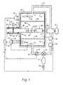
- FIG. 1is a cross section of a BIER vessel in accordance with the present invention
- FIG. 2is a schematic drawing showing a preferred door and tube in accordance with the present invention.
- FIG. 3is a schematic view of one embodiment of the sterilant supply system of FIG. 1 ;
- FIG. 4is a side sectional view of one embodiment of the sample holder and access port of FIG. 1 .
- a biological indicator evaluator resistomer (BIER) vesselis shown.
- the BIER vesselis suited to the evaluation of the effects of vapor and gaseous sterilants on biological indicators, for D-value determination of biological indicators, and study of chemical indicators, chemical kinetics, material compatibility, process development, sensor or instrument calibration, packaging, and other material device evaluations.
- Bio indicatorstypically contain a known population of a selected microorganism, such as a bacterial spore, which is known to be at least as resistant to a vapor sterilization process as the microorganisms that the sterilization process is expected to kill or deactivate. After the sterilization process, the microorganism is cultured in a growth medium for a sufficient period for any remaining viable microorganisms to grow. The growing microorganisms are detected by physical examination or by other known techniques. Chemical indicators contain a chemical (or chemicals) which exhibits a detectable change, such as a chemical or physical change, on exposure to the sterilization process. For example, the chemical may react with the sterilant to produce a color change.
- a chemicalor chemicals
- the vesselincludes a chamber wall 10 which defines an interior chamber 12 .
- a vapor entry port 14 and a vapor exit port 16are defined in the chamber wall 10 .
- a generator 20supplies the chamber 12 with a sterilant vapor, preferably a vaporized peroxy compound, such as hydrogen peroxide, peracetic acid vapor, or a mixture thereof, entrained in a carrier gas, such as air.
- a circulating systemincludes a vapor inlet line 24 , which carries the vapor from the generator 20 to the entry port 14 .
- the hydrogen peroxidepasses through the chamber 12 and leaves the chamber through the exit port 16 .
- a return line 26returns the hydrogen peroxide to the generator.
- the vapor leaving the chamber 12is directed through a destroyer, such as a catalytic converter 32 which converts the vapor to non-harmful products, such as water and oxygen. Vaporized hydrogen peroxide is flowed through the chamber 12 until selected sterilization conditions are reached in terms of temperature, pressure and hydrogen peroxide concentration.
- the generator 20is preferably one which generates a controllable stream of vaporized hydrogen peroxide.
- a particularly preferred generatoris one which vaporizes droplets of liquid hydrogen peroxide on a heated plate and entrains the vapor in a stream of carrier gas, such as air. The gas is then transported with the vapor to the chamber 12 .
- the liquid hydrogen peroxideis optionally supplied from a single source 34 as a mixture of hydrogen peroxide in water for example, a 5-95% by weight hydrogen peroxide solution, more preferably, 30-35% hydrogen peroxide.
- the liquid componentsare entirely converted to vapor, so the resulting vapor has the same concentration of hydrogen peroxide as the liquid from which it is generated.
- the components of the vaporare separately contained so that the composition of the vapor is adjustable by varying the rate of supply of each component to the vaporizer 20 .
- a sourcesuch as a reservoir 40 of concentrated hydrogen peroxide and a source 42 of water (or more dilute hydrogen peroxide), which may be a reservoir, as shown in FIG. 3 , or a water supply line, are connected with the vaporizer 20 by supply lines 44 and 46 , respectively.
- the two sources 40 , 42are separate so that the hydrogen peroxide solution and water can be supplied to the generator at separately variable rates.
- the concentration of hydrogen peroxide in the multi-component vaporis adjustable by increasing the rate at which the concentrated hydrogen peroxide solution is supplied to the vaporizer, or by lowering the rate at which the water (or dilute hydrogen peroxide solution) is supplied, or by both increasing rate at which the concentrated hydrogen peroxide solution is supplied and lowering the rate at which the water/dilute solution is supplied. In this way, there is the opportunity to increase the concentration of hydrogen peroxide in the chamber 12 without simultaneously increasing the water vapor concentration.
- the hydrogen peroxide in the reservoir 40typically contains water, but the water concentration of the hydrogen peroxide solution is preferably at or below the minimum desired concentration of water in the chamber 12 , so that different selected hydrogen peroxide concentrations are achieved by mixing fluid from both reservoirs 40 , 42 in selected ratios. Additionally, since hydrogen peroxide decomposes in the chamber, generating water vapor, the ratio of the two components in the feed is preferably varied, as appropriate, throughout a single sterilization test to maintain the hydrogen peroxide concentration and water vapor (humidity) levels in the chamber independently at desired levels. Thus, the hydrogen peroxide concentration of the liquid entering the vaporizer towards the end of a sterilization test is preferably slightly higher than the selected hydrogen peroxide concentration in the chamber.
- removing the spent vapor from the chambermay not be necessary, other than to accommodate pressure changes due to the additional vapor entering through the inlet (or may take place at a lower rate than in a single source system). This is because the relative concentration of the vapor can be adjusted or maintained at a selected level primarily by adjusting the ratio of the two components in the feed. Thus, the overall consumption of hydrogen peroxide liquid is generally lower when separate sources 40 , 42 of hydrogen peroxide and water are employed.
- the vaporized mixture of water and hydrogen peroxideis mixed with a carrier gas, such as air, which is supplied to the vaporizer through a line 48 (FIG. 3 ).
- a filter 50such as a HEPA filter, preferably filters the air.
- the airmay also be passed through a drier 52 , to remove moisture, and through a heater 54 , to raise the temperature of the carrier gas, prior to mixing the carrier gas with the hydrogen peroxide vapor.
- first and second pumps 58 , 60pump the hydrogen peroxide solution and water from the reservoirs 40 and 42 , respectively.
- a single pump(not shown) pumps the solution from the reservoir 34 to the generator 20 .
- Separately adjustable regulator valves 62 , 64regulate the fluid flow rate through the lines 44 , 46 .
- regulation of the flow ratesis adjusted by adjusting the pumping rate of the pumps 58 , 60 .
- a single pump 66replaces pumps 58 , 60 .
- the chamber wall 10is preferably constructed from a material which exhibits low reactivity towards hydrogen peroxide, such as passivated stainless steel.
- the chamber wall 10is of rigid construction to allow for exposures requiring sub-atmospheric pressures or elevated pressures, and for maintaining the internal pressure. Fluctuations in pressure are not uncommon in conventional BIER vessels due to changes in ambient conditions and the flexibility of the chamber walls. Decreasing the flexibility in the walls 10 improves the reproducibility of the test conditions.
- a particularly preferred chamber 12is one with a volume of about 0.7 cubic meters or less. Significantly smaller volumes are not required where the gaseous hydrogen peroxide generator 20 is one which can control the concentration and flow accurately.
- a thermal jacket 68such as a water jacket or a resistance heater, surrounds substantially all of the chamber 12 .
- the jacket 68serves to maintain a selected temperature within the chamber.
- a heater 70connected to the thermal jacket 68 , heats the jacket.
- the chamber 12is insulated to reduce heat loss from the chamber.
- the thermal jacket 68optionally includes a cooling device, such as a cold water jacket.
- additional insulation of unjacketed areas, such as doorsfurther serves to maintain the internal temperature of the chamber 12 .
- an opening 74 in the chamber wall 10is sealed by a door 76 .
- the dooris heated to assist in maintaining a uniform temperature within the chamber.
- the door 76opens to allow access to the chamber for repairs and maintenance, and optionally to introduce biological indicators and larger items through the opening 74 into the chamber 12 . More preferably, the biological indicators are introduced to the chamber through a small opening 80 formed in the door 76 , or elsewhere in the chamber wall 10 .
- an access port 82permits rapid insertion of items to be tested into the chamber without unduly perturbing the chamber conditions.
- the access portpreferably includes a hollow tube 84 , which extends outwardly from the door 76 around the opening 80 .
- the tube 84defines an interior passageway 85 , which is shaped to receive a sample holder or D-tube 86 . As shown in FIG. 2 , both the tube 84 and the sample holder 86 have D-shaped cross sections to ensure proper orientation of the sample holder when inserted through the tube into the chamber, although other configurations are also contemplated.
- the sample holder 86has a number of slots 88 or other receptacles for holding items A, such as biological indicators, to be exposed to the chamber conditions. Or, as shown in FIG. 4 , items may be supported on a rod 89 in a single slot 88 .
- the access port 82is constructed to minimize the flow of gas or vapor into or out from the chamber 12 while the biological indicators are being admitted to the chamber to avoid perturbing the equilibrium conditions.
- the biological indicatorsare thus exposed relatively instantaneously to the preselected equilibrium sterilization conditions.
- two seals 90 , 92are mounted within the tube 84 (FIG. 1 ).
- the seals 90 , 92may be in the shape of generally annular rings, formed, for example, from rubber, which form a seal between the sample holder 86 and the tube 84 .
- the sealsmay be in the shape of flap valves, or the like.
- the sealsmay be mounted on the sample holder 84 , for example, in annular grooves on the exterior.
- the tube interior passageway 85is closed by a valve 96 .
- the sample holder 86is long enough that a rearward end 98 of the sample holder remains in the port 82 when a forward end 100 of the holder is fully inserted into the chamber 12 .
- at least one of the seals 90 , 92contacts the exterior surface of the rearward end of the holder and thereby inhibits leakage of fluid into or out of the chamber 12 .
- the seal(s)contact the forward end 100 of the sample holder and inhibit leakage.
- both the forward and rear ends 98 , 100are closed, the slot or slots 88 forming an intermediate portion of the sample holder 86 between the two ends.
- a heating element 102such as a heating tape, or other suitable heating element, surrounds the tube 86 , at least in the region where the samples are placed (See FIG. 4 ).
- the sample holder 86may be left in this position for a sufficient time to allow the indicators A, or other samples in the sample holder, to warm up, preferably to reach the chamber temperature. This inhibits or prevents condensation on the samples which could otherwise occur if cold samples are inserted into the chamber 12 .
- a stop in the form of a projection 103optionally extends from the wall 10 to position the forward end 100 away from the wall.
- the stopmay be in the form of a flange 103 ′ which extends radially from the rearward end 98 of the sample holder. The flange 103 engages the tube 84 and limits the inward movement of the sample holder.
- the indicatorsare removed from the chamber 12 , by reversing the insertion process, and evaluated for remaining biological activity, or otherwise examined to determine the effects of the sterilization process or other factors related to the indicators or process under investigation.
- a fan, or fans 104mixes the gases within the chamber, thereby improving the uniformity of the mixture and increasing the rate of flow of sterilant over the biological indicators.
- Perforated upper and lower plates 106 and 108respectively, disposed within the chamber, serve to induce a laminar flow of gas through the chamber, thereby more closely resembling the flow of vaporized hydrogen peroxide through certain conventional sterilization chambers.
- the fans 104 and plates 106 and 108are positioned so that the vaporized hydrogen peroxide entering the chamber 12 is first mixed by the fans and then passes through the first plate 106 before flowing over the biological indicators A. The vaporized hydrogen peroxide then passes over the lower plate 108 before leaving the chamber 10 . Without the perforated plates 106 and 108 , turbulent flow sterilizers are simulated.
- the flow of vaporized hydrogen peroxide from the generator 20is further controlled by a flow control device 110 , such as a pump, vacuum source or blower, damper, or other regulator, which serves to regulate the flow of vaporized hydrogen peroxide into or out from the chamber 12 .
- a flow control device 110such as a pump, vacuum source or blower, damper, or other regulator, which serves to regulate the flow of vaporized hydrogen peroxide into or out from the chamber 12 .
- the flow control device 110is located in the inlet line 24 or the return line 26 .
- FIG. 4an embodiment of the tube 84 and sample holder 86 suited to use in a vacuum chamber 12 is shown.
- the suction on the sample holder 86tends to draw the sample holder back along the tube 84 and into the chamber after the sample holder has been withdrawn.
- a tube engagement system 120is provided.
- the system 120preferably includes one or more indents, such as annular grooves 122 (three are shown in FIG. 4 ), formed in either an interior surface 123 of the tube wall or on the sample holder 86 .
- the indents 122receive biased elements 124 , such as spring-biased ball bearings, carried by the other of the interior surface of the tube wall 123 or on the sample holder 86 .
- biased elements 124such as spring-biased ball bearings, carried by the other of the interior surface of the tube wall 123 or on the sample holder 86 .
- the ball bearings 124are retained in sockets 126 , and are carried by the sockets as the sample holder moves in or out of the chamber 12 .
- the ball bearings 124are biased outwardly from their sockets 126 and on reaching an adjacent groove 122 , enter the groove.
- the sample holder 86is thereby locked to the tube 84 inhibiting further movement of the sample holder 86 along the tube 84 .
- the griping force provided by the engagement of the ball bearings in the groovemay be overcome, if needed, by pulling on the sample holder with the hand.
- probes 160such as temperature, pressure and humidity probes, are disposed within the chamber 12 .
- the probes 160serve to measure the chamber environment.
- the probesare connected to a monitor 162 which monitors the changes in environmental conditions.
- the monitor 162signals a controller 164 which controls the environmental conditions within the chamber 12 by controlling the heater 70 for regulating the temperature of the thermal jacket 68 and also the operation of the flow control 110 , the vaporized hydrogen peroxide generator 20 , the pumps 58 , 60 , and the valves 62 , 64 .
- a sensor 166is also positioned within the chamber to detect hydrogen peroxide concentration directly and/or detect the concentration of other components of the vapor from which the hydrogen peroxide concentration can be established indirectly.
- the sensoris preferably a radiation sensor, such as an infrared sensor.
- the sensoruses near infrared (NIR) detection at two specific wavelengths, one corresponding to a predominantly hydrogen peroxide peak, the other to a water peak. There is some overlap between the peroxide and water peaks. By manipulating the data, the contribution of water is subtracted out and the hydrogen peroxide concentration determined.
- NIRnear infrared
- a vacuum source 170such as a pump evacuates the chamber 12 before, during, or after the sterilization process.
- a three-way valve 172 in line 26is connected to the vacuum pump 170 .
- the valve 172By switching the valve 172 between a first position, in which chamber gases passing through line 26 are returned to the generator 20 , to a second position in which the chamber gases are directed to the pump 170 , the chamber 12 is evacuated.
- a catalytic converter 174 and drier 176decompose the peroxy vapor and dry and heat the air before it is reintroduced into the generator 10 .
- the systemis used without recirculation of hydrogen peroxide or carrier gas.
- the air and hydrogen peroxideflows through the chamber in a single pass then is vented from the chamber via the catalytic converter 32 . This provides for better control of the system.
- the controller 164may take the form of a personal computer with a monitor 180 which displays the set parameters and other relevant information, such as the actual values of the parameters on a screen.
- the computermay be hooked up to a printer 182 , which provides a printout of the cycle conditions at the end of a cycle.
- the operatorinterfaces with the controller via a user interface, such as a keyboard 183 , keypad 184 , touch screen 186 , or the like.
- the controllerfeeds prompts to a display on the touch screen 186 and the operator enters the desired cycle parameters on the touch screen in response to the prompts.
- the controller 164then controls the cycle in accordance with the selected parameters.
- the controlleroptionally signals an alarm and/or aborts the cycle in the event that the parameters cannot be achieved, or example, if there is a leak in the system or one of the reservoirs 40 , 42 becomes empty.
- controller 164 and user interface 183 , 184 , 186may be integrally packaged with the chamber 12 and have dedicated software for ease of operator use.
- the touch screenmay be mounted, for example, to the door 76 or wall 10 of the chamber for ease of access.
- the controller 164has a number of options, including increasing the hydrogen peroxide concentration in the chamber by increasing the vaporization rate or by increasing the proportion of hydrogen peroxide in the liquid flowing to the vaporizer by adjusting the valve 62 and/or valve 64 . Having two separate reservoirs, one for hydrogen peroxide and one for water, allows for more careful control of chamber conditions. The hydrogen peroxide concentration of the chamber can thus be adjusted up or down independently of the water vapor concentration (humidity). For example, if the controller 164 adds hydrogen peroxide to the chamber, this will displace some of the air and water in the chamber (i.e., by reducing the concentration of the water), and also increase the pressure within the chamber.
- the controllerautomatically compensates for these changes by allowing gas to leave the chamber to maintain the desired set point pressure and by adding additional water to maintain the set point water concentration.
- the controllerrapidly stabilizes the chamber parameters, such as temperature, pressure, humidity, and hydrogen peroxide concentration, at the set points and maintains the steady state during an exposure cycle.
- the chamber 12is preferably brought to the desired exposure conditions prior to insertion of the biological indicators or other items to be exposed.
- the indicatorsequilibrate rapidly to the exposure conditions.
- the process of withdrawalquickly stops the sterilization process by rapidly removing the indicators from the sterilizer.
Landscapes
- Health & Medical Sciences (AREA)
- Chemical & Material Sciences (AREA)
- Life Sciences & Earth Sciences (AREA)
- Epidemiology (AREA)
- Organic Chemistry (AREA)
- General Health & Medical Sciences (AREA)
- Public Health (AREA)
- Engineering & Computer Science (AREA)
- Animal Behavior & Ethology (AREA)
- Zoology (AREA)
- Wood Science & Technology (AREA)
- Proteomics, Peptides & Aminoacids (AREA)
- Veterinary Medicine (AREA)
- Molecular Biology (AREA)
- Biochemistry (AREA)
- Microbiology (AREA)
- Physics & Mathematics (AREA)
- Biotechnology (AREA)
- Biophysics (AREA)
- Analytical Chemistry (AREA)
- Immunology (AREA)
- Bioinformatics & Cheminformatics (AREA)
- General Engineering & Computer Science (AREA)
- Genetics & Genomics (AREA)
- Chemical Kinetics & Catalysis (AREA)
- General Chemical & Material Sciences (AREA)
- Apparatus For Disinfection Or Sterilisation (AREA)
Abstract
Description
This application claims the priority of U.S. Provisional Application Ser. No. 60/284,426, filed Apr. 17, 2001.
The present invention relates to the sterilization arts. It finds particular application in conjunction with biological indicator evaluator resistomer (BIER) vessels for evaluating biological indicators used for determining the effectiveness of vaporized hydrogen peroxide (VHP) sterilization processes and will be described with particular reference thereto. It should be appreciated, however, that the invention is also applicable to use with other sterilants, including ethylene oxide, steam, other oxidants in the vapor phase, such as peracetic acid, and the like.
Sterilization and disinfection are important tools for destroying harmful organisms which may otherwise contaminate medical, dental, surgical, pharmaceutical, food processing, and other equipment. Vaporized hydrogen peroxide is a particularly useful agent for this purpose. Because it is effective at low temperatures (below 80° C.), thermal degradation of materials susceptible to heat, such as medical and dental instruments, plastic, containers, and plastic contact lenses, is avoided. In addition, decomposition of the vapor results in the formation of water and oxygen, which are environmentally and biologically safe by-products.
BIER vessels are widely used for the purpose of evaluating the performance characteristics of biological indicators of the type used in the medical industry for ensuring adequate sterilization of equipment. Biological indicators typically employ a calibrated population of microbial spores which are subjected to the decontamination process. Remaining spore viability following the process is indicative of a processing defect.
BIER vessels differ from conventional sterilizers in that they allow a high level of control and monitoring of the process conditions within the vessel. Such vessels commonly employ a small (about 10-30 liters), temperature-controlled chamber. Ideally, during evaluation of a biological indicator, the indicator is exposed within the BIER vessel under equilibrium conditions with respect to the sterilant in terms of pressure, temperature, relative humidity and sterilant concentration for a selected time period. BIER vessels are designed to both generate and end the equilibrium (or square wave) conditions “instantaneously,” by rapid introduction of the sterilant to the vessel at the required temperature and pressure and subsequent evacuation on completion of the exposure to the sterilant. Instantaneous exposure to, and subsequent evacuation or flushing of the sterilant from the chamber eliminates residual kill of the test microorganisms and provides an accurate assessment of the biological indicator relative to the particular agent being evaluated.
Current BIER vessel technology is adapted specifically for one of two agents: steam or ethylene oxide gas. For both of these agents, steady state conditions are readily achieved, virtually instantaneously. In the case of steam, steady state conditions are achieved in minimal time, for a relatively small chamber, by rapid introduction of the steam under pressure into the chamber. The environment is sustained by intermittent pulsing of steam into the chamber as necessary to maintain a selected temperature and pressure. In the case of ethylene oxide, uniform chamber conditions are achieved by a single injection of a specified volume of gas. As with a steam BIER vessel, the introduction of the agent to a small chamber and the time in which steady state conditions are achieved can be considered instantaneous for ethylene oxide.
The technology developed for use with steam and ethylene oxide agents is unsuited to use with vaporized hydrogen peroxide. Vaporized hydrogen peroxide is a unique sterilant, requiring low vapor pressure for effective sterilization. High pressures cause condensation of the gas, reducing its effectiveness as a sterilant and disinfectant. High temperatures tend to cause decomposition of the gas at both atmospheric and vacuum pressures. In addition, hydrogen peroxide gas is highly reactive, decomposing upon contact with a wide variety of inorganic and organic substances. A single injection of hydrogen peroxide, or intermittent pulses, are generally ineffective as the gas does not remain intact for prolonged periods due to its reactivity. The rate of degradation is difficult to predict since it varies due to a number of factors, including temperature, absorbency of the load, and the like. Conventional methods of achieving equilibrium conditions are therefore unsuited for use with vaporized hydrogen peroxide.
Further, conventional systems for evaluating biological indicators employ a flexible walled chamber, or isolator, which does not allow for optimal temperature control, thorough mixing of the agent throughout the chamber, or sub-atmospheric pressure control.
The release of the sterilant into a closed chamber affects the pressure within the chamber. The effect is most pronounced when the system is operating under a high vacuum. Under such conditions, small fluctuations in the weight of sterilant released have a relatively large influence on the chamber pressure. Where diluting gases are present in the chamber, changes in pressure tend to affect the antimicrobial activity of the sterilant by altering the mean free path of the gas molecules, resulting in changes in the frequency with which the sterilant molecules come into contact with the surfaces of the material being exposed to the sterilant.
The present invention provides a new and improved BIER vessel and method of operation which overcome the above referenced problems, with respect to vaporized hydrogen peroxide, and others.
In accordance with one aspect of the present invention, a system for evaluating biological indicators is provided. The system includes a chamber and an access port for selectively introducing biological indicators into the chamber and for subsequently removing the biological indicators from the chamber. A generator is provided for generating a multi-component sterilant vapor. A circulating system supplies the multi-component sterilant vapor to the chamber. A source of a first component of the multi-component sterilant vapor is fluidly connected with the vaporizer. A source of a second component of the multi-component sterilant vapor is fluidly connected with the vaporizer.
In accordance with another aspect of the present invention, a system for evaluating biological indicators is provided. The system includes a chamber. An access port is provided for selectively introducing biological indicators into the chamber and for subsequently removing the biological indicators from the chamber. The access port includes a tube having a cross section shaped to receive a sample holder therethrough and an opening in fluid communication with the chamber at one end thereof. A valve selectively closes the opening. A generator generates a multi-component sterilant vapor. A circulating system supplies the multi-component sterilant vapor to the chamber.
In accordance with another aspect of the present invention, a method of evaluating a biological indicator is provided. The method includes generating a multi-component vapor from a first component and a second component. The multi-component vapor is passed through a test chamber until steady state conditions are achieved. The biological indicator to be evaluated is introduced into the chamber. The steady state conditions are maintained for a selected period, including adjusting a ratio of the first component to the second component in the multi-component vapor and introducing the adjusted multi-component vapor to the test chamber. The biological indicator is removed from the test chamber after a preselected time period and the effects upon the indicator are assessed.
In accordance with another aspect of the present invention, an evaluation system is provided. The system includes a vessel which defines an interior chamber. A source of an antimicrobial fluid supplies the antimicrobial fluid to the chamber. A tube is fluidly connected with the chamber. The tube extends from the vessel for receiving a sample holder therein. The sample holder carries a sample to be evaluated and is movable within the tube between a first position, in which the sample is positioned outside the chamber and a second position, in which the sample is positioned inside the chamber to be exposed to the antimicrobial fluid. A means for applying suction to the chamber is provided. A means is associated with at least one of the tube and the sample holder for resisting movement of the sample holder into the chamber under the influence of a reduced pressure applied by the suction means.
In accordance with another aspect of the present invention, a method of evaluating an effect of an antimicrobial process upon an indicator for the process is provided. The method includes supplying an antimicrobial fluid to the chamber, positioning the indicator on a sample holder, inserting the sample holder into a first end of a tube which is fluidly connected with a chamber at a second end, and opening a valve which seals the chamber from the second end of the tube. The method further includes pushing the sample holder through the tube until the indicator is positioned within the chamber and exposing the indicator to the antimicrobial fluid in the chamber. The sample holder is withdrawn from the chamber and the indicator evaluated to determine the effect of the antimicrobial process upon the indicator.
One advantage of the present invention is that a reproducible vaporized hydrogen peroxide environment is created for evaluation of biological indicators.
Another advantage of the present invention is that a homogeneous distribution of the sterilant within the chamber is achieved.
Another advantage of the present invention is that the agent is flowed through the chamber, thereby exposing the biological indicator to a continuous stream of fresh sterilant.
Still further advantages of the present invention will become apparent to those of ordinary skill in the art upon reading and understanding the following detailed description of the preferred embodiments.
The invention may take form in various components and arrangements of components, and in various steps and arrangements of steps. The drawings are only for purposes of illustrating a preferred embodiment and are not to be construed as limiting the invention.
With reference toFIGS. 1 and 2 , a biological indicator evaluator resistomer (BIER) vessel is shown. The BIER vessel is suited to the evaluation of the effects of vapor and gaseous sterilants on biological indicators, for D-value determination of biological indicators, and study of chemical indicators, chemical kinetics, material compatibility, process development, sensor or instrument calibration, packaging, and other material device evaluations.
Biological indicators typically contain a known population of a selected microorganism, such as a bacterial spore, which is known to be at least as resistant to a vapor sterilization process as the microorganisms that the sterilization process is expected to kill or deactivate. After the sterilization process, the microorganism is cultured in a growth medium for a sufficient period for any remaining viable microorganisms to grow. The growing microorganisms are detected by physical examination or by other known techniques. Chemical indicators contain a chemical (or chemicals) which exhibits a detectable change, such as a chemical or physical change, on exposure to the sterilization process. For example, the chemical may react with the sterilant to produce a color change.
The vessel includes achamber wall 10 which defines aninterior chamber 12. Avapor entry port 14 and avapor exit port 16 are defined in thechamber wall 10. Agenerator 20 supplies thechamber 12 with a sterilant vapor, preferably a vaporized peroxy compound, such as hydrogen peroxide, peracetic acid vapor, or a mixture thereof, entrained in a carrier gas, such as air.
While the system will be described with particular reference to vapor hydrogen peroxide as the sterilant, it will be appreciated that other vaporous and gaseous sterilants are contemplated. Moreover, while reference is made to sterilants and sterilization, it will be appreciated that the system is also useful for assessing other levels of microbial decontamination, including disinfection and sanitization.
A circulating system includes avapor inlet line 24, which carries the vapor from thegenerator 20 to theentry port 14. The hydrogen peroxide passes through thechamber 12 and leaves the chamber through theexit port 16. Optionally, areturn line 26 returns the hydrogen peroxide to the generator. Alternatively, the vapor leaving thechamber 12 is directed through a destroyer, such as acatalytic converter 32 which converts the vapor to non-harmful products, such as water and oxygen. Vaporized hydrogen peroxide is flowed through thechamber 12 until selected sterilization conditions are reached in terms of temperature, pressure and hydrogen peroxide concentration.
Thegenerator 20 is preferably one which generates a controllable stream of vaporized hydrogen peroxide. A particularly preferred generator is one which vaporizes droplets of liquid hydrogen peroxide on a heated plate and entrains the vapor in a stream of carrier gas, such as air. The gas is then transported with the vapor to thechamber 12.
The liquid hydrogen peroxide is optionally supplied from asingle source 34 as a mixture of hydrogen peroxide in water for example, a 5-95% by weight hydrogen peroxide solution, more preferably, 30-35% hydrogen peroxide. The liquid components are entirely converted to vapor, so the resulting vapor has the same concentration of hydrogen peroxide as the liquid from which it is generated.
With reference toFIG. 3 , in an alternative embodiment, the components of the vapor are separately contained so that the composition of the vapor is adjustable by varying the rate of supply of each component to thevaporizer 20. A source, such as areservoir 40 of concentrated hydrogen peroxide and asource 42 of water (or more dilute hydrogen peroxide), which may be a reservoir, as shown inFIG. 3 , or a water supply line, are connected with thevaporizer 20 bysupply lines sources chamber 12 without simultaneously increasing the water vapor concentration.
It will be appreciated that the hydrogen peroxide in thereservoir 40 typically contains water, but the water concentration of the hydrogen peroxide solution is preferably at or below the minimum desired concentration of water in thechamber 12, so that different selected hydrogen peroxide concentrations are achieved by mixing fluid from bothreservoirs
When a two source system is used, as shown inFIG. 3 , removing the spent vapor from the chamber may not be necessary, other than to accommodate pressure changes due to the additional vapor entering through the inlet (or may take place at a lower rate than in a single source system). This is because the relative concentration of the vapor can be adjusted or maintained at a selected level primarily by adjusting the ratio of the two components in the feed. Thus, the overall consumption of hydrogen peroxide liquid is generally lower whenseparate sources
In contrast, if asingle source 34 of hydrogen peroxide/water is used, as shown inFIG. 1 , the water vapor concentration tends to increase with time, due to the conversion of hydrogen peroxide to water. To compensate for this, it is preferable to remove the spent vapor from the chamber at a relatively rapid rate and replenish it with fresh vapor at the desired hydrogen peroxide concentration.
The vaporized mixture of water and hydrogen peroxide is mixed with a carrier gas, such as air, which is supplied to the vaporizer through a line48 (FIG.3). Afilter 50, such as a HEPA filter, preferably filters the air. The air may also be passed through a drier52, to remove moisture, and through aheater 54, to raise the temperature of the carrier gas, prior to mixing the carrier gas with the hydrogen peroxide vapor.
In the embodiment ofFIG. 3 , first andsecond pumps reservoirs FIG. 1 , a single pump (not shown) pumps the solution from thereservoir 34 to thegenerator 20. Separatelyadjustable regulator valves lines pumps FIG. 2 , asingle pump 66 replacespumps
Thechamber wall 10 is preferably constructed from a material which exhibits low reactivity towards hydrogen peroxide, such as passivated stainless steel. Preferably, thechamber wall 10 is of rigid construction to allow for exposures requiring sub-atmospheric pressures or elevated pressures, and for maintaining the internal pressure. Fluctuations in pressure are not uncommon in conventional BIER vessels due to changes in ambient conditions and the flexibility of the chamber walls. Decreasing the flexibility in thewalls 10 improves the reproducibility of the test conditions. A particularly preferredchamber 12 is one with a volume of about 0.7 cubic meters or less. Significantly smaller volumes are not required where the gaseoushydrogen peroxide generator 20 is one which can control the concentration and flow accurately.
With reference once more toFIG. 1 , athermal jacket 68, such as a water jacket or a resistance heater, surrounds substantially all of thechamber 12. Thejacket 68 serves to maintain a selected temperature within the chamber. Aheater 70, connected to thethermal jacket 68, heats the jacket. Alternatively, or additionally, thechamber 12 is insulated to reduce heat loss from the chamber. Where sub-ambient exposure temperatures are required, thethermal jacket 68 optionally includes a cooling device, such as a cold water jacket. In a particularly preferred embodiment, additional insulation of unjacketed areas, such as doors, further serves to maintain the internal temperature of thechamber 12.
With continued reference toFIG. 1 , anopening 74 in thechamber wall 10 is sealed by adoor 76. Optionally the door is heated to assist in maintaining a uniform temperature within the chamber. Thedoor 76 opens to allow access to the chamber for repairs and maintenance, and optionally to introduce biological indicators and larger items through theopening 74 into thechamber 12. More preferably, the biological indicators are introduced to the chamber through asmall opening 80 formed in thedoor 76, or elsewhere in thechamber wall 10. As shown inFIGS. 1 and 2 , anaccess port 82 permits rapid insertion of items to be tested into the chamber without unduly perturbing the chamber conditions. The access port preferably includes ahollow tube 84, which extends outwardly from thedoor 76 around theopening 80. Thetube 84 defines aninterior passageway 85, which is shaped to receive a sample holder or D-tube 86. As shown inFIG. 2 , both thetube 84 and thesample holder 86 have D-shaped cross sections to ensure proper orientation of the sample holder when inserted through the tube into the chamber, although other configurations are also contemplated.
Thesample holder 86 has a number ofslots 88 or other receptacles for holding items A, such as biological indicators, to be exposed to the chamber conditions. Or, as shown inFIG. 4 , items may be supported on arod 89 in asingle slot 88.
Preferably, theaccess port 82 is constructed to minimize the flow of gas or vapor into or out from thechamber 12 while the biological indicators are being admitted to the chamber to avoid perturbing the equilibrium conditions. The biological indicators are thus exposed relatively instantaneously to the preselected equilibrium sterilization conditions. In this respect, twoseals seals sample holder 86 and thetube 84. Or, the seals may be in the shape of flap valves, or the like. Alternatively, the seals may be mounted on thesample holder 84, for example, in annular grooves on the exterior.
When not in use, the tubeinterior passageway 85 is closed by avalve 96. As shown inFIG. 1 , thesample holder 86 is long enough that arearward end 98 of the sample holder remains in theport 82 when aforward end 100 of the holder is fully inserted into thechamber 12. In this position, at least one of theseals chamber 12. Prior to insertion, the seal(s) contact theforward end 100 of the sample holder and inhibit leakage. As can be seen fromFIG. 1 , both the forward andrear ends slots 88 forming an intermediate portion of thesample holder 86 between the two ends.
To insert thesample holder 86 into the chamber, the operator pushes the sample holder into the tube until theforward end 100 reaches thevalve 96. At this time, theexterior seal 90 is in engagement with theforward end 100 of the sample holder. Preferably, aheating element 102, such as a heating tape, or other suitable heating element, surrounds thetube 86, at least in the region where the samples are placed (See FIG.4). Thesample holder 86 may be left in this position for a sufficient time to allow the indicators A, or other samples in the sample holder, to warm up, preferably to reach the chamber temperature. This inhibits or prevents condensation on the samples which could otherwise occur if cold samples are inserted into thechamber 12.
The operator then opens thevalve 96 and quickly pushes thesample holder 86 as far as it will go into the chamber. This movement correctly and reproducibly positions the biological indicators in the chamber. The space between the sample holder and thetube 84 is closed by at least one of theseals FIG. 1 , a stop in the form of aprojection 103 optionally extends from thewall 10 to position theforward end 100 away from the wall. Alternatively, or additionally the stop may be in the form of aflange 103′ which extends radially from therearward end 98 of the sample holder. Theflange 103 engages thetube 84 and limits the inward movement of the sample holder.
After a selected exposure period, the indicators are removed from thechamber 12, by reversing the insertion process, and evaluated for remaining biological activity, or otherwise examined to determine the effects of the sterilization process or other factors related to the indicators or process under investigation.
In the illustrated embodiment, a fan, orfans 104, preferably disposed within thechamber 12, mixes the gases within the chamber, thereby improving the uniformity of the mixture and increasing the rate of flow of sterilant over the biological indicators. Perforated upper andlower plates fans 104 andplates chamber 12 is first mixed by the fans and then passes through thefirst plate 106 before flowing over the biological indicators A. The vaporized hydrogen peroxide then passes over thelower plate 108 before leaving thechamber 10. Without theperforated plates
Optionally, the flow of vaporized hydrogen peroxide from thegenerator 20 is further controlled by aflow control device 110, such as a pump, vacuum source or blower, damper, or other regulator, which serves to regulate the flow of vaporized hydrogen peroxide into or out from thechamber 12. Preferably, theflow control device 110 is located in theinlet line 24 or thereturn line 26.
With particular reference toFIG. 4 , an embodiment of thetube 84 andsample holder 86 suited to use in avacuum chamber 12 is shown. When thechamber 12 is subjected to a vacuum, the suction on thesample holder 86 tends to draw the sample holder back along thetube 84 and into the chamber after the sample holder has been withdrawn. To ensure that the exposed sample holder is not accidentally drawn back into thechamber 12 by the vacuum, atube engagement system 120 is provided. Thesystem 120 preferably includes one or more indents, such as annular grooves122 (three are shown in FIG.4), formed in either aninterior surface 123 of the tube wall or on thesample holder 86. Theindents 122 receivebiased elements 124, such as spring-biased ball bearings, carried by the other of the interior surface of thetube wall 123 or on thesample holder 86. As shown inFIG. 4 , theball bearings 124 are retained insockets 126, and are carried by the sockets as the sample holder moves in or out of thechamber 12. When thesample holder 86 is drawn back toward thechamber 12 by vacuum pressure, theball bearings 124 are biased outwardly from theirsockets 126 and on reaching anadjacent groove 122, enter the groove. Thesample holder 86 is thereby locked to thetube 84 inhibiting further movement of thesample holder 86 along thetube 84. The griping force provided by the engagement of the ball bearings in the groove may be overcome, if needed, by pulling on the sample holder with the hand.
With reference once more toFIG. 1 , probes160, such as temperature, pressure and humidity probes, are disposed within thechamber 12. Theprobes 160 serve to measure the chamber environment. The probes are connected to amonitor 162 which monitors the changes in environmental conditions. Preferably, themonitor 162 signals acontroller 164 which controls the environmental conditions within thechamber 12 by controlling theheater 70 for regulating the temperature of thethermal jacket 68 and also the operation of theflow control 110, the vaporizedhydrogen peroxide generator 20, thepumps valves
Asensor 166 is also positioned within the chamber to detect hydrogen peroxide concentration directly and/or detect the concentration of other components of the vapor from which the hydrogen peroxide concentration can be established indirectly. The sensor is preferably a radiation sensor, such as an infrared sensor. In one embodiment, the sensor uses near infrared (NIR) detection at two specific wavelengths, one corresponding to a predominantly hydrogen peroxide peak, the other to a water peak. There is some overlap between the peroxide and water peaks. By manipulating the data, the contribution of water is subtracted out and the hydrogen peroxide concentration determined.
Optionally, avacuum source 170, such as a pump, evacuates thechamber 12 before, during, or after the sterilization process. Optionally, a three-way valve 172 inline 26 is connected to thevacuum pump 170. By switching thevalve 172 between a first position, in which chamber gases passing throughline 26 are returned to thegenerator 20, to a second position in which the chamber gases are directed to thepump 170, thechamber 12 is evacuated. Optionally, acatalytic converter 174 and drier176 decompose the peroxy vapor and dry and heat the air before it is reintroduced into thegenerator 10.
More preferably, the system is used without recirculation of hydrogen peroxide or carrier gas. The air and hydrogen peroxide flows through the chamber in a single pass then is vented from the chamber via thecatalytic converter 32. This provides for better control of the system.
With reference toFIG. 2 , thecontroller 164 may take the form of a personal computer with amonitor 180 which displays the set parameters and other relevant information, such as the actual values of the parameters on a screen. The computer may be hooked up to aprinter 182, which provides a printout of the cycle conditions at the end of a cycle. The operator interfaces with the controller via a user interface, such as akeyboard 183,keypad 184,touch screen 186, or the like. In a preferred embodiment, the controller feeds prompts to a display on thetouch screen 186 and the operator enters the desired cycle parameters on the touch screen in response to the prompts. Thecontroller 164 then controls the cycle in accordance with the selected parameters. The controller optionally signals an alarm and/or aborts the cycle in the event that the parameters cannot be achieved, or example, if there is a leak in the system or one of thereservoirs
As will be appreciated, thecontroller 164 anduser interface chamber 12 and have dedicated software for ease of operator use. The touch screen may be mounted, for example, to thedoor 76 orwall 10 of the chamber for ease of access.
If the hydrogen peroxide concentration is lower than a target level, thecontroller 164 has a number of options, including increasing the hydrogen peroxide concentration in the chamber by increasing the vaporization rate or by increasing the proportion of hydrogen peroxide in the liquid flowing to the vaporizer by adjusting thevalve 62 and/orvalve 64. Having two separate reservoirs, one for hydrogen peroxide and one for water, allows for more careful control of chamber conditions. The hydrogen peroxide concentration of the chamber can thus be adjusted up or down independently of the water vapor concentration (humidity). For example, if thecontroller 164 adds hydrogen peroxide to the chamber, this will displace some of the air and water in the chamber (i.e., by reducing the concentration of the water), and also increase the pressure within the chamber. The controller automatically compensates for these changes by allowing gas to leave the chamber to maintain the desired set point pressure and by adding additional water to maintain the set point water concentration. By using suitably tuned control algorithms, the controller rapidly stabilizes the chamber parameters, such as temperature, pressure, humidity, and hydrogen peroxide concentration, at the set points and maintains the steady state during an exposure cycle.
Thechamber 12 is preferably brought to the desired exposure conditions prior to insertion of the biological indicators or other items to be exposed. Thus, the indicators equilibrate rapidly to the exposure conditions. Similarly, on withdrawal of the indicators from the chamber, the process of withdrawal quickly stops the sterilization process by rapidly removing the indicators from the sterilizer.
The invention has been described with reference to the preferred embodiment. Obviously, modifications and alterations will occur to others upon reading and understanding the preceding detailed description. It is intended that the invention be construed as including all such modifications and alterations insofar as they come within the scope of the appended claims or the equivalents thereof.
Claims (28)
1. A system for evaluating biological indicators comprising:
a) a chamber;
b) an access port for selectively introducing biological indicators into the chamber and for subsequently removing the biological indicators from the chamber;
c) a generator for generating a multi-component sterilant vapor;
d) a circulating system for supplying the multi-component sterilant vapor to the chamber;
e) a source of a first component of the multi-component sterilant vapor fluidly connected with the vaporizer; and
f) a source of a second component of the multi-component sterilant vapor, separate from the first source, fluidly connected with the vaporizer.
2. The system ofclaim 1 , wherein the multi-component sterilant vapor comprises a vaporized peroxy compound and water vapor.
3. The system ofclaim 2 , wherein the peroxy compound includes at least one of hydrogen peroxide and peracetic acid.
4. The system ofclaim 1 , further including:
at least one regulator which regulates the flow of one of the first and second components to the generator.
5. The system ofclaim 1 , wherein the chamber is constructed of a material that is rigid under vacuum and pressure and further including a pump for at least one of drawing the chamber to sub-atmospheric pressure and pumping the chamber to above-atmospheric pressure.
6. The system ofclaim 1 , further including a heater for selectively heating or a cooling system for cooling walls of the chamber.
7. The system ofclaim 1 , further including a fan for mixing gases within the chamber.
8. The system ofclaim 1 , further including a sample holder for supporting items within the chamber.
9. The system ofclaim 8 , wherein the access port includes a tube configured for receiving the sample holder.
10. The system ofclaim 9 , wherein the access port further includes a valve for selectively closing the tube to seal the chamber.
11. The system ofclaim 9 , wherein the access port includes at least one seal, the seal engaging a first portion of the sample holder when a second portion of the sample holder is positioned within the chamber.
12. The system ofclaim 1 , wherein the circulating system circulates the multi-component sterilant vapor through the chamber and includes a device for controlling a flow rate of the multi-component sterilant vapor through the chamber.
13. The system ofclaim 1 , further including probes for measuring environmental conditions within the chamber.
14. The system ofclaim 1 , further including a controller for monitoring environmental conditions within the chamber, the controller controlling at least one of:
a heater for heating the chamber,
a cooling system for cooling the chamber,
a fan for circulating the multi-component sterilant vapor through the chamber,
a pump for adjusting pressure within the chamber,
a regulator for regulating component flow into the chamber, and
the generator.
15. A system for evaluating biological indicators comprising:
a) a chamber;
b) an access port for selectively introducing biological indicators into the chamber and for subsequently removing the biological indicators from the chamber, the access port including:
a tube having a cross section shaped to receive a sample holder therethrough and an opening in fluid communication with the chamber at one end thereof, and
a valve which selectively closes the opening;
c) a generator for generating a multi-component sterilant vapor;
d) a circulating system for supplying the multi-component sterilant vapor to the chamber.
16. The system ofclaim 15 , further including:
at least one seal mounted within the tube which contacts the sample holder to seal the access port during an exposure cycle.
17. A method of evaluating a biological indicator comprising:
generating a multi-component vapor from a first component and a second component;
passing the multi-component vapor through a test chamber until steady state conditions are achieved;
introducing the biological indicator to be evaluated into the chamber;
maintaining the steady state conditions for a selected period, including adjusting a ratio of the first component to the second component in the multi-component vapor and introducing the adjusted multi-component vapor to the test chamber;
removing the biological indicator from the test chamber after a preselected time period;
assessing the effects upon the indicator.
18. The method ofclaim 17 , wherein the multi-component vapor includes at least one of hydrogen peroxide and peracetic acid vapor.
19. The method ofclaim 17 , further including monitoring and controlling temperature within the chamber.
20. The method ofclaim 17 , further including monitoring and controlling the pressure within the chamber.
21. The method ofclaim 17 , further including monitoring environmental conditions in the test chamber and controlling at least one of:
flow of the multi-component vapor;
temperature in the chamber;
pressure in the test chamber.
22. The method ofclaim 17 , further including positioning the biological indicator in a sample holder, the step of introducing the indicator including:
inserting the sample holder through an access port, and, during the step of maintaining the steady state conditions:
sealing a gap between an exterior portion of the sample holder and the access port.
23. An evaluation system:
a vessel which defines an interior chamber;
a source of an antimicrobial fluid which supplies the antimicrobial fluid to the chamber;
a tube, fluidly connected with the chamber, which extends from the vessel for receiving a sample holder therein, the sample holder carrying a sample to be evaluated and being movable within the tube between a first position, in which the sample is positioned outside the chamber and a second position, in which the sample is positioned inside the chamber to be exposed to the antimicrobial fluid;
means for applying suction to the chamber;
means associated with at least one of the tube and the sample holder, for resisting movement of the sample holder into the chamber under the influence of a reduced pressure applied by the suction means.
24. The evaluation system ofclaim 23 , wherein the resisting means include:
a groove in one of the tube and the sample holder; and
a biased element associated with the other of the tube and the sample holder, the biased element entering the groove as the sample holder is drawn into the chamber by the reduced pressure, resisting further movement of the sample holder into the chamber.
25. The evaluation system ofclaim 23 , wherein the biased element includes a plurality of spring biased ball bearings.
26. The evaluation system ofclaim 23 , wherein the groove includes a plurality of spaced, generally annular grooves.
27. The evaluation system ofclaim 23 , further including a valve which selectively seals the chamber from the tube.
28. A method of evaluating an effect of an antimicrobial process upon an indicator for the process, the method including:
a) supplying an antimicrobial fluid to the chamber;
b) positioning the indicator on a sample holder;
c) inserting the sample holder into a first end of a tube which is fluidly connected with a chamber at a second end;
d) opening a valve which seals the chamber from the second end of the tube;
e) pushing the sample holder through the tube until the indicator is positioned within the chamber;
f) exposing the indicator to the antimicrobial fluid in the chamber;
g) withdrawing the sample holder from the chamber; and
h) evaluating the indicator to determine the effect of the antimicrobial process upon the indicator.
Priority Applications (1)
| Application Number | Priority Date | Filing Date | Title |
|---|---|---|---|
| US10/124,384US6936434B2 (en) | 2001-04-17 | 2002-04-17 | Vapor phase decontamination process biological indicator evaluator resistomer (BIER) vessel |
Applications Claiming Priority (2)
| Application Number | Priority Date | Filing Date | Title |
|---|---|---|---|
| US28442601P | 2001-04-17 | 2001-04-17 | |
| US10/124,384US6936434B2 (en) | 2001-04-17 | 2002-04-17 | Vapor phase decontamination process biological indicator evaluator resistomer (BIER) vessel |
Publications (2)
| Publication Number | Publication Date |
|---|---|
| US20020160440A1 US20020160440A1 (en) | 2002-10-31 |
| US6936434B2true US6936434B2 (en) | 2005-08-30 |
Family
ID=26822518
Family Applications (1)
| Application Number | Title | Priority Date | Filing Date |
|---|---|---|---|
| US10/124,384Expired - LifetimeUS6936434B2 (en) | 2001-04-17 | 2002-04-17 | Vapor phase decontamination process biological indicator evaluator resistomer (BIER) vessel |
Country Status (1)
| Country | Link |
|---|---|
| US (1) | US6936434B2 (en) |
Cited By (17)
| Publication number | Priority date | Publication date | Assignee | Title |
|---|---|---|---|---|
| US20050276721A1 (en)* | 2004-05-25 | 2005-12-15 | Steris Inc. | Method and apparatus for controlling the concentration of a sterilant chemical in a fluid |
| US20070253859A1 (en)* | 2006-05-01 | 2007-11-01 | Steris Inc. | Hydrogen peroxide vaporizer |
| US20070258915A1 (en)* | 2006-05-02 | 2007-11-08 | Andrew Kielbania | Anti-Microbial Composition and Method for Making and Using Same |
| US20070271814A1 (en)* | 2004-08-18 | 2007-11-29 | Bae Sun C | Apparatus For Automatically Drying And Method For Controlling The Same |
| US20080279720A1 (en)* | 2007-03-06 | 2008-11-13 | Meilander Timothy W | Decontamination unit with collapsible decontamination enclosure and decontamination process |
| US20090074881A1 (en)* | 2006-05-02 | 2009-03-19 | Bioneutral Laboratories Corporation Usa | Antimicrobial cidality formulations with residual efficacy, uses thereof, and the preparation thereof |
| US20090114252A1 (en)* | 2007-11-02 | 2009-05-07 | Steris Inc. | Method and apparatus for drying objects in a washer |
| DE102009039547A1 (en) | 2009-09-01 | 2011-03-03 | Khs Gmbh | Evaluating disinfection and/or sterilization process through the determination of resistance of microbiological materials, by arranging indicator objects or samples in the form of carrier substrate on an object carrier of a testing device |
| US20130094992A1 (en)* | 2011-10-06 | 2013-04-18 | Canon Marketing Japan Kabushiki Kaisha | Sterilization apparatus and sterilization method |
| US8865065B2 (en)* | 2013-01-09 | 2014-10-21 | Global Ozone Innovations, Llc | Ozone sanitizing system |
| US8975067B2 (en) | 2010-12-22 | 2015-03-10 | 3M Innovative Properties Company | Self-contained sterilization indicators including a neutralizer for residual oxidizing sterilant |
| US20150099262A1 (en)* | 2013-10-03 | 2015-04-09 | Becton, Dickinson And Company | Flow cytometer biosafety hood and systems including the same |
| US10443083B2 (en) | 2016-03-02 | 2019-10-15 | Asp Global Manufacturing Gmbh | Apparatus and method for analyzing biological indicators |
| US10561753B2 (en) | 2016-03-02 | 2020-02-18 | Asp Global Manufacturing Gmbh | Method of sterilizing medical devices, analyzing biological indicators, and linking medical device sterilization equipment |
| US10596287B2 (en) | 2016-03-02 | 2020-03-24 | Asp Global Manufacturing Gmbh | Apparatus and method to link medical device sterilization equipment |
| US10668180B2 (en) | 2016-03-02 | 2020-06-02 | Asp Global Manufacturing Gmbh | Apparatus and method for sterilizing medical devices |
| US10864291B2 (en) | 2017-12-26 | 2020-12-15 | Asp Global Manufacturing Gmbh | Process and apparatus for cleaning, disinfection, sterilization, or combinations thereof |
Families Citing this family (13)
| Publication number | Priority date | Publication date | Assignee | Title |
|---|---|---|---|---|
| US6936434B2 (en)* | 2001-04-17 | 2005-08-30 | Steris Inc. | Vapor phase decontamination process biological indicator evaluator resistomer (BIER) vessel |
| DE20118185U1 (en)* | 2001-11-09 | 2003-03-20 | Leybold Vakuum GmbH, 50968 Köln | vacuum pump |
| AU2004320230A1 (en)* | 2003-06-05 | 2006-02-02 | Gregory L. Noss | Sterilization system and method |
| US7357896B2 (en)* | 2003-06-30 | 2008-04-15 | Ethicon, Inc. | Resistometer |
| US7544325B2 (en)* | 2003-11-25 | 2009-06-09 | American Sterilizer Company | BIER vessel high-speed biological indicator shuttling system |
| ITMI20050506A1 (en)* | 2005-03-24 | 2006-09-25 | Fedegari Autoclavi | METHOD FOR THE CHARACTERIZATION OF BIOLOGICAL INDICATORS IN THE PROCESSES OF STERILIZATION AND EQUIPMENT FOR ITS IMPLEMENTATION |
| CN2851928Y (en)* | 2005-12-05 | 2006-12-27 | 丁祺恒 | Air purification and filtration system |
| US7926368B2 (en)* | 2006-11-01 | 2011-04-19 | Zefon International, Inc. | Humidity-controlled gas-borne matter collection device |
| US11951223B2 (en) | 2018-06-29 | 2024-04-09 | Asp Global Manufacturing Gmbh | Method and apparatus for cleaning, disinfection, sterilization, or combinations thereof |
| WO2020068031A1 (en)* | 2018-09-24 | 2020-04-02 | Oh Pharmaceutical Co., Ltd. | Infusion system |
| US12076458B2 (en)* | 2020-05-13 | 2024-09-03 | American Sterilizer Company | Disinfection process sampling device |
| US20220001059A1 (en)* | 2020-07-02 | 2022-01-06 | Koninklijke Philips N.V. | Decontamination of respiratory equipment |
| TWI883274B (en)* | 2020-10-02 | 2025-05-11 | 日商新田股份有限公司 | Decontamination device and decontamination method |
Citations (22)
| Publication number | Priority date | Publication date | Assignee | Title |
|---|---|---|---|---|
| US4158040A (en) | 1978-03-20 | 1979-06-12 | American Sterilizer Company | Rapid sterilization evaluator and test apparatus |
| US4169123A (en) | 1975-12-11 | 1979-09-25 | Moore-Perk Corporation | Hydrogen peroxide vapor sterilization method |
| US4744951A (en) | 1983-11-07 | 1988-05-17 | American Sterilizer Company | Vaporization method to enhance sterilant penetration |
| US4909999A (en) | 1987-07-06 | 1990-03-20 | American Sterilizer Company | Flow-through vapor phase sterilization system |
| US4952370A (en) | 1988-05-06 | 1990-08-28 | American Sterilizer Company | Hydrogen peroxide sterilization method |
| US4956145A (en) | 1987-12-30 | 1990-09-11 | American Sterilizer Company | Optimum hydrogen peroxide vapor sterilization method |
| US5152968A (en)* | 1990-12-17 | 1992-10-06 | Elopak Systems A.G. | Single pass vapor generation container sterilization system |
| US5445792A (en) | 1992-03-13 | 1995-08-29 | American Sterilizer Company | Optimum hydrogen peroxide vapor sterlization method |
| US5482684A (en) | 1994-05-03 | 1996-01-09 | Abtox, Inc. | Vessel useful for monitoring plasma sterilizing processes |
| US5498526A (en) | 1993-08-25 | 1996-03-12 | Abtox, Inc. | Bacillus circulans based biological indicator for gaseous sterilants |
| US5759848A (en) | 1996-05-14 | 1998-06-02 | Fujiyakuhin Co., Ltd. | Biological indicator |
| US5788925A (en) | 1996-02-16 | 1998-08-04 | Steris Corporation | Method for real time monitoring and control of load sterilization and parametric release |
| US5801010A (en) | 1997-03-17 | 1998-09-01 | Surigot, Inc. | Self-contained biological indicator for non traditional sterilization methods |
| US5834313A (en)* | 1997-09-19 | 1998-11-10 | Johnson & Johnson Medical, Inc. | Container monitoring system |
| US5869000A (en)* | 1997-06-20 | 1999-02-09 | Johnson & Johnson Medical, Inc. | Partial vapor removal through exhaust port |
| US5872359A (en) | 1995-07-27 | 1999-02-16 | American Sterilizer Company | Real-time monitor and control system and method for hydrogen peroxide vapor decontamination |
| US5876664A (en) | 1996-06-14 | 1999-03-02 | American Sterilizer Company | Continuous-operation, closed loop decontamination system and method |
| US5906794A (en) | 1995-06-15 | 1999-05-25 | American Sterilizer Company | Continuous-operation, closed loop decontamination system and method |
| US6036918A (en)* | 1993-03-17 | 2000-03-14 | Enviro Medical Systems, Inc. | Vapor sterilization |
| US6077480A (en)* | 1997-06-19 | 2000-06-20 | Steris Corporation | Multiple flashpoint vaporization system |
| US20020160440A1 (en)* | 2001-04-17 | 2002-10-31 | Mcdonnell Gerald E. | Vapor phase decontamination process biological indicator evaluator resistomer (BIER) vessel |
| US20030086820A1 (en)* | 2001-10-05 | 2003-05-08 | Steris Inc. | Decontamination of surfaces contaminated with prion-infected material with gaseous oxidixing agents |
- 2002
- 2002-04-17USUS10/124,384patent/US6936434B2/ennot_activeExpired - Lifetime
Patent Citations (22)
| Publication number | Priority date | Publication date | Assignee | Title |
|---|---|---|---|---|
| US4169123A (en) | 1975-12-11 | 1979-09-25 | Moore-Perk Corporation | Hydrogen peroxide vapor sterilization method |
| US4158040A (en) | 1978-03-20 | 1979-06-12 | American Sterilizer Company | Rapid sterilization evaluator and test apparatus |
| US4744951A (en) | 1983-11-07 | 1988-05-17 | American Sterilizer Company | Vaporization method to enhance sterilant penetration |
| US4909999A (en) | 1987-07-06 | 1990-03-20 | American Sterilizer Company | Flow-through vapor phase sterilization system |
| US4956145A (en) | 1987-12-30 | 1990-09-11 | American Sterilizer Company | Optimum hydrogen peroxide vapor sterilization method |
| US4952370A (en) | 1988-05-06 | 1990-08-28 | American Sterilizer Company | Hydrogen peroxide sterilization method |
| US5152968A (en)* | 1990-12-17 | 1992-10-06 | Elopak Systems A.G. | Single pass vapor generation container sterilization system |
| US5445792A (en) | 1992-03-13 | 1995-08-29 | American Sterilizer Company | Optimum hydrogen peroxide vapor sterlization method |
| US6036918A (en)* | 1993-03-17 | 2000-03-14 | Enviro Medical Systems, Inc. | Vapor sterilization |
| US5498526A (en) | 1993-08-25 | 1996-03-12 | Abtox, Inc. | Bacillus circulans based biological indicator for gaseous sterilants |
| US5482684A (en) | 1994-05-03 | 1996-01-09 | Abtox, Inc. | Vessel useful for monitoring plasma sterilizing processes |
| US5906794A (en) | 1995-06-15 | 1999-05-25 | American Sterilizer Company | Continuous-operation, closed loop decontamination system and method |
| US5872359A (en) | 1995-07-27 | 1999-02-16 | American Sterilizer Company | Real-time monitor and control system and method for hydrogen peroxide vapor decontamination |
| US5788925A (en) | 1996-02-16 | 1998-08-04 | Steris Corporation | Method for real time monitoring and control of load sterilization and parametric release |
| US5759848A (en) | 1996-05-14 | 1998-06-02 | Fujiyakuhin Co., Ltd. | Biological indicator |
| US5876664A (en) | 1996-06-14 | 1999-03-02 | American Sterilizer Company | Continuous-operation, closed loop decontamination system and method |
| US5801010A (en) | 1997-03-17 | 1998-09-01 | Surigot, Inc. | Self-contained biological indicator for non traditional sterilization methods |
| US6077480A (en)* | 1997-06-19 | 2000-06-20 | Steris Corporation | Multiple flashpoint vaporization system |
| US5869000A (en)* | 1997-06-20 | 1999-02-09 | Johnson & Johnson Medical, Inc. | Partial vapor removal through exhaust port |
| US5834313A (en)* | 1997-09-19 | 1998-11-10 | Johnson & Johnson Medical, Inc. | Container monitoring system |
| US20020160440A1 (en)* | 2001-04-17 | 2002-10-31 | Mcdonnell Gerald E. | Vapor phase decontamination process biological indicator evaluator resistomer (BIER) vessel |
| US20030086820A1 (en)* | 2001-10-05 | 2003-05-08 | Steris Inc. | Decontamination of surfaces contaminated with prion-infected material with gaseous oxidixing agents |
Cited By (42)
| Publication number | Priority date | Publication date | Assignee | Title |
|---|---|---|---|---|
| US20080063574A1 (en)* | 2004-05-25 | 2008-03-13 | Steris Corporation | Apparatus for controlling the concentration of a sterilant chemical in a fluid |
| US7611667B2 (en)* | 2004-05-25 | 2009-11-03 | Steris Corporation | Apparatus for controlling the concentration of a sterilant chemical in a fluid |
| US20050276721A1 (en)* | 2004-05-25 | 2005-12-15 | Steris Inc. | Method and apparatus for controlling the concentration of a sterilant chemical in a fluid |
| US7900374B2 (en)* | 2004-08-18 | 2011-03-08 | Lg Electronics Inc. | Apparatus for automatically drying and method for controlling the same |
| US20070271814A1 (en)* | 2004-08-18 | 2007-11-29 | Bae Sun C | Apparatus For Automatically Drying And Method For Controlling The Same |
| US8349272B2 (en) | 2006-05-01 | 2013-01-08 | American Sterilizer Company | Hydrogen peroxide vaporizer |
| WO2007130852A3 (en)* | 2006-05-01 | 2008-06-05 | American Sterilizer Co | Hydrogen peroxide vaporizer |
| US8071021B2 (en) | 2006-05-01 | 2011-12-06 | American Sterilizer Company | Hydrogen peroxide vaporizer |
| CN101522225B (en)* | 2006-05-01 | 2012-11-07 | 美国消毒公司 | Hydrogen peroxide vaporizer |
| US20070253859A1 (en)* | 2006-05-01 | 2007-11-01 | Steris Inc. | Hydrogen peroxide vaporizer |
| US20090074881A1 (en)* | 2006-05-02 | 2009-03-19 | Bioneutral Laboratories Corporation Usa | Antimicrobial cidality formulations with residual efficacy, uses thereof, and the preparation thereof |
| US20070258915A1 (en)* | 2006-05-02 | 2007-11-08 | Andrew Kielbania | Anti-Microbial Composition and Method for Making and Using Same |
| US9034390B2 (en) | 2006-05-02 | 2015-05-19 | Bioneutral Laboratories Corporation | Anti-microbial composition and method for making and using same |
| US20080279722A1 (en)* | 2007-03-06 | 2008-11-13 | Bacik Michael A | Transportable decontamination unit and decontamination process |
| US20080279721A1 (en)* | 2007-03-06 | 2008-11-13 | Weiss Richard A | Decontamination unit and process |
| US8182743B1 (en) | 2007-03-06 | 2012-05-22 | Steris Inc. | Transportable decontamination unit and decontamination process |
| US7993601B2 (en) | 2007-03-06 | 2011-08-09 | Steris Inc. | Decontamination unit and process |
| US20080279720A1 (en)* | 2007-03-06 | 2008-11-13 | Meilander Timothy W | Decontamination unit with collapsible decontamination enclosure and decontamination process |
| US8128888B2 (en) | 2007-03-06 | 2012-03-06 | Steris Inc. | Transportable decontamination unit and decontamination process |
| US8153078B2 (en) | 2007-03-06 | 2012-04-10 | Steris Inc. | Transportable decontamination unit and decontamination process |
| US8163236B1 (en) | 2007-03-06 | 2012-04-24 | Steris Inc. | Transportable decontamination unit and decontamination process |
| US8216523B2 (en) | 2007-03-06 | 2012-07-10 | Steris Inc. | Decontamination unit with collapsible decontamination enclosure and decontamination process |
| US20090114252A1 (en)* | 2007-11-02 | 2009-05-07 | Steris Inc. | Method and apparatus for drying objects in a washer |
| US7841104B2 (en)* | 2007-11-02 | 2010-11-30 | Steris Inc. | Method and apparatus for drying objects in a washer |
| US20110005098A1 (en)* | 2007-11-02 | 2011-01-13 | Steris Inc. | Method for drying objects in a washer |
| US8176651B2 (en) | 2007-11-02 | 2012-05-15 | Steris Inc. | Method for drying objects in a washer |
| DE102009039547A1 (en) | 2009-09-01 | 2011-03-03 | Khs Gmbh | Evaluating disinfection and/or sterilization process through the determination of resistance of microbiological materials, by arranging indicator objects or samples in the form of carrier substrate on an object carrier of a testing device |
| US8975067B2 (en) | 2010-12-22 | 2015-03-10 | 3M Innovative Properties Company | Self-contained sterilization indicators including a neutralizer for residual oxidizing sterilant |
| US20130094992A1 (en)* | 2011-10-06 | 2013-04-18 | Canon Marketing Japan Kabushiki Kaisha | Sterilization apparatus and sterilization method |
| US8894926B2 (en)* | 2011-10-06 | 2014-11-25 | Canon Marketing Japan Kabushiki Kaisha | Sterilization apparatus and sterilization method |
| US8865065B2 (en)* | 2013-01-09 | 2014-10-21 | Global Ozone Innovations, Llc | Ozone sanitizing system |
| US9327040B2 (en) | 2013-01-09 | 2016-05-03 | Global Ozone Innovations, Llc | Ozone sanitizing system |
| US20150099262A1 (en)* | 2013-10-03 | 2015-04-09 | Becton, Dickinson And Company | Flow cytometer biosafety hood and systems including the same |
| US9446159B2 (en)* | 2013-10-03 | 2016-09-20 | Becton, Dickinson And Company | Flow cytometer biosafety hood and systems including the same |
| US10443083B2 (en) | 2016-03-02 | 2019-10-15 | Asp Global Manufacturing Gmbh | Apparatus and method for analyzing biological indicators |
| US10561753B2 (en) | 2016-03-02 | 2020-02-18 | Asp Global Manufacturing Gmbh | Method of sterilizing medical devices, analyzing biological indicators, and linking medical device sterilization equipment |
| US10596287B2 (en) | 2016-03-02 | 2020-03-24 | Asp Global Manufacturing Gmbh | Apparatus and method to link medical device sterilization equipment |
| US10668180B2 (en) | 2016-03-02 | 2020-06-02 | Asp Global Manufacturing Gmbh | Apparatus and method for sterilizing medical devices |
| US11390901B2 (en) | 2016-03-02 | 2022-07-19 | Asp Global Manufacturing Gmbh | Apparatus and method for analyzing biological indicators |
| US11660365B2 (en) | 2016-03-02 | 2023-05-30 | Asp Global Manufacturing Gmbh | Apparatus and method for sterilizing medical devices |
| US11766495B2 (en) | 2016-03-02 | 2023-09-26 | Asp Global Manufacturing Gmbh | Method of sterilizing medical devices, analyzing biological indicators, and linking medical device sterilization equipment |
| US10864291B2 (en) | 2017-12-26 | 2020-12-15 | Asp Global Manufacturing Gmbh | Process and apparatus for cleaning, disinfection, sterilization, or combinations thereof |
Also Published As
| Publication number | Publication date |
|---|---|
| US20020160440A1 (en) | 2002-10-31 |
Similar Documents
| Publication | Publication Date | Title |
|---|---|---|
| US6936434B2 (en) | Vapor phase decontamination process biological indicator evaluator resistomer (BIER) vessel | |
| EP0841955B1 (en) | Real-time monitor and control system and method for hydrogen peroxide vapor decontamination | |
| JP2722228B2 (en) | Method for removing contamination of living cells or the surface in the vicinity thereof using gas-phase hydrogen peroxide | |
| US11648327B2 (en) | Apparatus and method for sterilizing endoscope | |
| JP3877069B2 (en) | Method and apparatus for calibration of a device for monitoring sterilant concentration in a system | |
| EP1112751A1 (en) | Monitoring of sterilant apparatus and method for monitoring sterilant | |
| EP2000529B1 (en) | Culture apparatus | |
| CN105658246B (en) | Sterilization methods and equipment and their adaptive controls | |
| EP1226834B1 (en) | Formaldehyde gas sterilizer | |
| US7449145B2 (en) | Method for determining lumen penetration of a vapor phase sterilant | |
| US20110085938A1 (en) | Device and method for gas sterilization | |
| US6189368B1 (en) | Method and apparatus for detection of concentration of hydrogen peroxide vapor | |
| US20030012689A1 (en) | Apparatus for testing sterilization methods and materials | |
| CN101227931A (en) | Detection of sterilisation vapour condensation point | |
| US20230398251A1 (en) | Apparatus And Method For Sterilizing Endoscope | |
| JP3681538B2 (en) | Sterilization method, sterilization apparatus and sterility test apparatus | |
| Czarneski et al. | Isolator decontamination using chlorine dioxide gas | |
| JP2005021686A (en) | Sterilization/disinfection test system and control method for sterilization/disinfection treatment | |
| CN115814136A (en) | Indicator resistance instrument and method for monitoring ethylene oxide sterilization | |
| US20050112026A1 (en) | BIER vessel high-speed biological indicator shuttling system | |
| JP2002355278A (en) | Closed space atmosphere keeper | |
| US20230364286A1 (en) | Sterilization method | |
| JP4344702B2 (en) | Incubator | |
| Watling | Isolation technology: hydrogen peroxide decontamination |
Legal Events
| Date | Code | Title | Description |
|---|---|---|---|
| AS | Assignment | Owner name:STERIS INC., CALIFORNIA Free format text:ASSIGNMENT OF ASSIGNORS INTEREST;ASSIGNORS:MCDONNELL, GERALD E.;MCVEY, IAIN F.;GEANOUS, MICHAEL;REEL/FRAME:012995/0409 Effective date:20020426 | |
| STCF | Information on status: patent grant | Free format text:PATENTED CASE | |
| AS | Assignment | Owner name:AMERICAN STERILIZER COMPANY, OHIO Free format text:ASSIGNMENT OF ASSIGNORS INTEREST;ASSIGNOR:STERIS INC.;REEL/FRAME:020234/0745 Effective date:20071127 Owner name:AMERICAN STERILIZER COMPANY,OHIO Free format text:ASSIGNMENT OF ASSIGNORS INTEREST;ASSIGNOR:STERIS INC.;REEL/FRAME:020234/0745 Effective date:20071127 | |
| FPAY | Fee payment | Year of fee payment:4 | |
| FPAY | Fee payment | Year of fee payment:8 | |
| FPAY | Fee payment | Year of fee payment:12 |