US6936030B1 - Injector systems incorporating a base unit attached to a surface - Google Patents
Injector systems incorporating a base unit attached to a surfaceDownload PDFInfo
- Publication number
- US6936030B1 US6936030B1US10/006,586US658601AUS6936030B1US 6936030 B1US6936030 B1US 6936030B1US 658601 AUS658601 AUS 658601AUS 6936030 B1US6936030 B1US 6936030B1
- Authority
- US
- United States
- Prior art keywords
- injector system
- connecting member
- base unit
- injection head
- head unit
- Prior art date
- Legal status (The legal status is an assumption and is not a legal conclusion. Google has not performed a legal analysis and makes no representation as to the accuracy of the status listed.)
- Expired - Lifetime, expires
Links
- 238000002347injectionMethods0.000claimsabstractdescription44
- 239000007924injectionSubstances0.000claimsabstractdescription44
- 238000000034methodMethods0.000claimsabstractdescription25
- 239000012530fluidSubstances0.000claimsabstractdescription10
- 230000007246mechanismEffects0.000claimsdescription4
- 239000000853adhesiveSubstances0.000claimsdescription2
- 230000001070adhesive effectEffects0.000claimsdescription2
- 230000003213activating effectEffects0.000claims1
- 238000002595magnetic resonance imagingMethods0.000description10
- 238000004891communicationMethods0.000description6
- 229940039231contrast mediaDrugs0.000description5
- 239000002872contrast mediaSubstances0.000description5
- 238000003384imaging methodMethods0.000description5
- 238000002955isolationMethods0.000description3
- 239000000463materialSubstances0.000description3
- RYGMFSIKBFXOCR-UHFFFAOYSA-NCopperChemical compound[Cu]RYGMFSIKBFXOCR-UHFFFAOYSA-N0.000description2
- 230000008901benefitEffects0.000description2
- 239000011248coating agentSubstances0.000description2
- 238000000576coating methodMethods0.000description2
- 229910052802copperInorganic materials0.000description2
- 239000010949copperSubstances0.000description2
- 230000001419dependent effectEffects0.000description2
- 230000005670electromagnetic radiationEffects0.000description2
- 238000002604ultrasonographyMethods0.000description2
- 229910001369BrassInorganic materials0.000description1
- 238000005481NMR spectroscopyMethods0.000description1
- 238000002583angiographyMethods0.000description1
- 230000004888barrier functionEffects0.000description1
- 238000005452bendingMethods0.000description1
- 239000010951brassSubstances0.000description1
- 230000008859changeEffects0.000description1
- 238000002591computed tomographyMethods0.000description1
- 239000004020conductorSubstances0.000description1
- 238000013479data entryMethods0.000description1
- 238000002405diagnostic procedureMethods0.000description1
- 239000011521glassSubstances0.000description1
- PCHJSUWPFVWCPO-UHFFFAOYSA-NgoldChemical compound[Au]PCHJSUWPFVWCPO-UHFFFAOYSA-N0.000description1
- 239000010931goldSubstances0.000description1
- 229910052737goldInorganic materials0.000description1
- 230000002452interceptive effectEffects0.000description1
- 238000010999medical injectionMethods0.000description1
- 239000002184metalSubstances0.000description1
- 229910052751metalInorganic materials0.000description1
- 230000004048modificationEffects0.000description1
- 238000012986modificationMethods0.000description1
- 238000012545processingMethods0.000description1
- 238000000926separation methodMethods0.000description1
- 238000002560therapeutic procedureMethods0.000description1
Images


Classifications
- A—HUMAN NECESSITIES
- A61—MEDICAL OR VETERINARY SCIENCE; HYGIENE
- A61M—DEVICES FOR INTRODUCING MEDIA INTO, OR ONTO, THE BODY; DEVICES FOR TRANSDUCING BODY MEDIA OR FOR TAKING MEDIA FROM THE BODY; DEVICES FOR PRODUCING OR ENDING SLEEP OR STUPOR
- A61M5/00—Devices for bringing media into the body in a subcutaneous, intra-vascular or intramuscular way; Accessories therefor, e.g. filling or cleaning devices, arm-rests
- A61M5/14—Infusion devices, e.g. infusing by gravity; Blood infusion; Accessories therefor
- A61M5/1413—Modular systems comprising interconnecting elements
- A—HUMAN NECESSITIES
- A61—MEDICAL OR VETERINARY SCIENCE; HYGIENE
- A61M—DEVICES FOR INTRODUCING MEDIA INTO, OR ONTO, THE BODY; DEVICES FOR TRANSDUCING BODY MEDIA OR FOR TAKING MEDIA FROM THE BODY; DEVICES FOR PRODUCING OR ENDING SLEEP OR STUPOR
- A61M5/00—Devices for bringing media into the body in a subcutaneous, intra-vascular or intramuscular way; Accessories therefor, e.g. filling or cleaning devices, arm-rests
- A61M5/14—Infusion devices, e.g. infusing by gravity; Blood infusion; Accessories therefor
- A61M5/142—Pressure infusion, e.g. using pumps
- A61M5/145—Pressure infusion, e.g. using pumps using pressurised reservoirs, e.g. pressurised by means of pistons
- A61M5/1452—Pressure infusion, e.g. using pumps using pressurised reservoirs, e.g. pressurised by means of pistons pressurised by means of pistons
- A61M5/14546—Front-loading type injectors
- A—HUMAN NECESSITIES
- A61—MEDICAL OR VETERINARY SCIENCE; HYGIENE
- A61M—DEVICES FOR INTRODUCING MEDIA INTO, OR ONTO, THE BODY; DEVICES FOR TRANSDUCING BODY MEDIA OR FOR TAKING MEDIA FROM THE BODY; DEVICES FOR PRODUCING OR ENDING SLEEP OR STUPOR
- A61M5/00—Devices for bringing media into the body in a subcutaneous, intra-vascular or intramuscular way; Accessories therefor, e.g. filling or cleaning devices, arm-rests
- A61M5/007—Devices for bringing media into the body in a subcutaneous, intra-vascular or intramuscular way; Accessories therefor, e.g. filling or cleaning devices, arm-rests for contrast media
- Y—GENERAL TAGGING OF NEW TECHNOLOGICAL DEVELOPMENTS; GENERAL TAGGING OF CROSS-SECTIONAL TECHNOLOGIES SPANNING OVER SEVERAL SECTIONS OF THE IPC; TECHNICAL SUBJECTS COVERED BY FORMER USPC CROSS-REFERENCE ART COLLECTIONS [XRACs] AND DIGESTS
- Y10—TECHNICAL SUBJECTS COVERED BY FORMER USPC
- Y10S—TECHNICAL SUBJECTS COVERED BY FORMER USPC CROSS-REFERENCE ART COLLECTIONS [XRACs] AND DIGESTS
- Y10S128/00—Surgery
- Y10S128/01—Motorized syringe
- Y—GENERAL TAGGING OF NEW TECHNOLOGICAL DEVELOPMENTS; GENERAL TAGGING OF CROSS-SECTIONAL TECHNOLOGIES SPANNING OVER SEVERAL SECTIONS OF THE IPC; TECHNICAL SUBJECTS COVERED BY FORMER USPC CROSS-REFERENCE ART COLLECTIONS [XRACs] AND DIGESTS
- Y10—TECHNICAL SUBJECTS COVERED BY FORMER USPC
- Y10S—TECHNICAL SUBJECTS COVERED BY FORMER USPC CROSS-REFERENCE ART COLLECTIONS [XRACs] AND DIGESTS
- Y10S128/00—Surgery
- Y10S128/12—Pressure infusion
Definitions
- the present inventionrelates to powered injector systems and methods and, more particularly, to powered injector systems and methods that facilitate positioning of the powered injectors in medical injection procedures.
- a physician or other personinjects a patient with a fluid.
- a number of injector-actuated syringes and powered injectors for pressurized injection of fluids such as contrast mediahave been developed for use in procedures such as angiography, computed tomography, ultrasound and NMR/MRI.
- these powered injectorsare designed to deliver a preset amount of contrast media at a preset flow rate.
- the injection head of the powered injectoris placed relatively close to the patient without obstructing the movement of the medical personnel in the room.
- MRImagnetic resonance imaging
- Conventional MRI systemstypically include some form of electromagnetic isolation shield or barrier.
- a room enclosed by copper sheeting or conductive mesh materialisolates or shields the imaging system from undesirable sources of electromagnetic radiation, including the electromagnetic noise inherent in the atmosphere.
- theses shielded roomsare limited in size.
- mobile MRI systemshave recently been developed that are housed in even smaller, mobile units.
- the present inventionprovides an injector system for use in delivering a fluid to a patient in a medical procedure.
- the injector systemincludes an injection head unit including at least one pressurizing member.
- a connecting memberis attached to the injection head unit.
- the injector systemfurther includes a base unit having a base member that is attachable to a surface and a support member to which the connecting member is attachable.
- the pressurizing memberis in communicative connection with a remote power source via at least one non-rigid drive connection.
- the connecting memberis removably attachable to the support member.
- the connecting memberis rotatable within the support member.
- the support membercan, for example, include at least one bushing member within which the connecting member can rotate.
- the connecting membercan, for example, be generally cylindrical and include a passage therethrough, through which the non-rigid drive connection is connected to the pressurizing member.
- the base unitpreferably includes a passage or portal through which the non-rigid connection connects to the remote power source.
- the present inventionalso provides a method for delivering fluid to a patient in a medical procedure.
- the methodincludes attaching a base unit to a surface, and attaching an injection head unit to the base unit via a connecting member that cooperates with the base unit.
- the methodfurther includes attaching a pressurizing member in the injection head unit to a power source remote from the injection head and the base unit via at least one non-rigid drive connection.
- the present inventionfurther provides a method of adapting an injector system for use in confined spaces.
- the injector systemincludes an injection head unit, and a connecting member attached to the head unit at a first end of the connector and attached to a floor stand at a second end of the connecting member.
- the methodincludes providing a base unit adapted to be attachable to a surface, and removing the connecting member from attachment with the floor stand so that the second end of the connecting member is attachable to the base unit.
- the injector systemfurther includes a power source connected to at least one drive member in the injection head unit via at least one non-rigid drive connection.
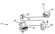
- FIGS. 1A and 1Billustrate an embodiment of a currently available injector system used in MRI procedures.
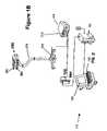
- FIG. 2illustrates a perspective view of one embodiment of an injector system of the present invention.
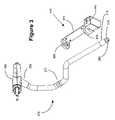
- FIG. 3illustrates a perspective view of the injection head unit and base unit of FIG. 2 in an disconnected state.
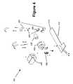
- FIG. 4illustrates a perspective view of the base unit of FIGS. 2 and 3 in a disassembled state.
- injectors systems and methods of the present inventionare not limited, however, to use in MRI procedures.
- injectors used in CT, ultrasound and angiographic imaging procedurescan be used with and incorporated into the present invention.
- FIGS. 1A and 1Billustrate a Spectris® injector system for use in a magnetic resonance imaging environment, which is currently available from Medrad, Inc. of Indianola, Pa., the Assignee of the present application.
- One embodiment of the injector system of FIGS. 1A and 1Bis described in U.S. Pat. No. 5,494,036, assigned to the Assignee of the present invention, the disclosure of which is incorporated herein by reference.
- the systemincludes an external system controller 100 that preferably includes a processing unit 110 (for example, a digital microcomputer), a battery charger 120 and an operator interface 125 (including, for example a data entry unit 125 ′ and a display 125 ′′).
- System controller 100is located outside of a shielded area such as an imaging room 150 that is shielded from electromagnetic interference by, for example, a shield 160 .
- Electromagnetic isolationcan, for example, be achieved by completely enclosing the room with copper sheet material or some other suitable, conductive layer such as wire mesh.
- Shielded imaging room 150preferably includes a patient viewing window 170 in shield 160 to allow an observer and/or operator to view the room without breaching electromagnetic shield 160 .
- Window 170can, for example, be formed by sandwiching a wire mesh material (not shown) between sheets of glass or by coating the window with a thin coating of conductive material such as gold (not shown) to maintain the continuity of electromagnetic shield 160 .
- the systemalso includes a contrast media injection control unit 200 located within shielded imaging room 150 .
- Injection control unit 200is preferably powered by a rechargeable battery 210 .
- Injection control unit 200preferably includes control circuitry which controls electric motors 220 and 220 ′, which are preferably located within injection control unit 200 .
- Injection control unit 200is preferably contained within an electromagnetic shield 230 to reduce or eliminate any undesired electromagnetic radiation generated by electric motors 220 and 220 ′ from interfering with the magnetic field used to generate the magnetic resonance image.
- Injection control unit 200can be separated (for example, by ten to fifteen feet) from injection head unit 250 , which is typically placed near the patient. As illustrated in FIG. 1B , injection head unit 250 is mounted on a mobile base unit 270 via a connecting member 275 .
- Injection head unit 250is preferably located in close proximity to the patient to decrease the distance that the contrast media fluid must travel from the contrast media from syringes 260 and 260 ′ (or other fluid chambers) connected to injection head unit 250 .
- Injection head unit 250further includes drive members 262 and 262 ′ such as pistons that act to pressurize the contents of syringes 260 and 260 ′, respectively, for injection into the patient.
- Drive members 262 and 262 ′are preferably connected to electric motors 220 and 220 ′, respectively, in injection control unit 200 by a non-rigid connection such as by flexible mechanical drive shafts 264 and 264 ′, respectively.
- Drive shafts 264 and 264 ′are preferably made from a nonferrous metal such as hard brass.
- injector control unit 200can be in communication with a communication unit 320 .
- control system 100can be in communication with a communication unit 330 .
- Communication units 320 , 330can, for example, communicate across viewing window 170 using light energy as disclosed in U.S. Pat. No. 5,494,036.
- FIGS. 2 through 4illustrate an embodiment of the present invention in which connecting member 275 cooperates with a stationary base unit 400 to enable positioning of injection head unit 250 in the vicinity of a patient in, for example, MRI rooms of little space, without substantially obstructing the mobility of medical personnel.
- base unit 400includes an attachment member or plate 410 that is attachable to, for example, a wall, a ceiling, a post or another surface (either generally flat or contoured) of a room via, for example, screws, adhesive or other attachment means or members. Screws or other attachment members can, for example, pass through holes 415 (see FIG. 4 ) in attachment plate 410 . Preferably, holes 415 are hidden from view/access when base unit 400 is fully assembled to reduce the likelihood that the attachment members will become loosened or detached and to enhance the appearance of base unit 400 .
- Base unit 400further preferably includes a support mechanism for removably retaining connecting member 275 therein.
- connecting member 275includes a number of connected sections of hollow tubing that are preferably attached (for example, via at least one coupler 277 ) so that they can be rotated relative to each other to provide mobility to injection head unit 250 .
- connecting member 275is preferably rotatably attached to in injection head unit 250 via, for example, a collar 252 .
- Connecting member 275is preferably releasably attachable to base unit 400 via, for example, at least one bushing 420 so that connecting member 275 is rotatable within base unit 400 . As illustrated in FIG.
- bushing 420includes two sections that are rotatably housed in a housing 424 .
- Bushing 420preferably includes an adapter mechanism to enable bushing 420 to accept and retain connecting members 275 of differing size and/or shape without introducing excessive play into the system.
- bushing 420can include biasing members or pads 426 (for example, spring-loaded abutment members or elastomeric pads) that act to securely grasp connecting member 275 .
- the compressibility of such members or pads 426enables use of connecting members 275 having, for example, variations in the diameter thereof without introducing play into the system.
- Housing 424attaches to attachment plate 410 via attachment members as known in the art (for example, screws) and can cover one or more of base plate attachment holes 415 when base 400 is assembled as described above.
- base unit 400also includes a second bushing unit or bushing housing 430 that includes a bushing (not shown) similar to bushing 420 .
- the bushing of bushing unit 430cooperates with a distal end of connecting member 275 to rotatably attach connecting member 275 to base unit 400 .
- Bushing unit 430can, for example, include a retainer as known in the art (for example, an adapter nut) that rotatably and removably attaches connecting member 275 to base unit 400 during use thereof via, for example, a threaded end 278 on connecting member 275 .
- bushing unit 430includes an adapter 432 having a tapered inner bore that matches a tapered portion 279 of connecting member 275 .
- the outer surface of adapter 432is generally cylindrical and rotatably seats within bushing unit 430 .
- Base unit 400further preferably includes a passage or portal 440 to allow a power source to pass therethrough and subsequently through connecting member 275 (via, for example, passage 280 therein) to provide power to drive members 262 and 262 ′ as discussed above.
- the power sourcecan, for example, be flexible mechanical drive shafts 264 and 264 as discussed above.
- base unit 400preferably includes at least one guide 450 that prevents excessive bending of the flexible mechanical drive shaft(s) in the area(s) in which such shafts change direction. In one embodiment, for example, a guide with a minimum radius of approximately three inches was used.
- other power sourcessuch as hydraulic or pneumatic lines can be used as a source of power.
- the injection head unit and connecting member of the existing injector systemare preferably directly usable with base unit 400 of the present invention with little or no modification thereof.
- bushing 420 , the bushing of bushing unit 430 and adapter 432are preferably sized and generally adapted to accommodate the connecting member of the existing injector system.
- the retaining member (not shown) of base unit 400is also adapted to accept the connecting member of the exiting injector system.
- injector systemshaving a power source that is not remotely connected to a drive mechanism via a non-rigid connection can also be used with the present invention.
- injector systemsare the EnVision CTTM and Medrad Vistron CT® injectors provided by Medrad, Inc., the Assignee of the present application.
Landscapes
- Health & Medical Sciences (AREA)
- Vascular Medicine (AREA)
- Engineering & Computer Science (AREA)
- Anesthesiology (AREA)
- Biomedical Technology (AREA)
- Heart & Thoracic Surgery (AREA)
- Hematology (AREA)
- Life Sciences & Earth Sciences (AREA)
- Animal Behavior & Ethology (AREA)
- General Health & Medical Sciences (AREA)
- Public Health (AREA)
- Veterinary Medicine (AREA)
- Infusion, Injection, And Reservoir Apparatuses (AREA)
Abstract
Description
This application claims the benefit of U.S. Provisional Application Ser. No. 60/247,356, entitled POWERED INJECTOR SYSTEMS, filed on Nov. 8, 2000, the disclosure of which is incorporated herein by reference.
The present invention relates to powered injector systems and methods and, more particularly, to powered injector systems and methods that facilitate positioning of the powered injectors in medical injection procedures.
In many medical diagnostic and therapeutic procedures, a physician or other person injects a patient with a fluid. In recent years, a number of injector-actuated syringes and powered injectors for pressurized injection of fluids such as contrast media have been developed for use in procedures such as angiography, computed tomography, ultrasound and NMR/MRI. In general, these powered injectors are designed to deliver a preset amount of contrast media at a preset flow rate.
In many situations in which a powered injector is used, space is limited and there are difficulties in properly placing the powered injector for optimal fluid delivery to the patient as well as for optimal movement of medical personnel working around the powered injector. Ideally, the injection head of the powered injector is placed relatively close to the patient without obstructing the movement of the medical personnel in the room.
The problem of injector positioning is typically heightened in a magnetic resonance imaging (MRI) environment. In general, MRI systems require isolation from external sources of electromagnetic noise to optimize image quality. Conventional MRI systems, therefore, typically include some form of electromagnetic isolation shield or barrier. Most often, a room enclosed by copper sheeting or conductive mesh material isolates or shields the imaging system from undesirable sources of electromagnetic radiation, including the electromagnetic noise inherent in the atmosphere. Typically, theses shielded rooms are limited in size. Moreover, mobile MRI systems have recently been developed that are housed in even smaller, mobile units.
It is very desirable to develop injectors, injector systems and methods to facilitate injection proceedings.
In one aspect, the present invention provides an injector system for use in delivering a fluid to a patient in a medical procedure. The injector system includes an injection head unit including at least one pressurizing member. A connecting member is attached to the injection head unit. The injector system further includes a base unit having a base member that is attachable to a surface and a support member to which the connecting member is attachable. In a dependent aspect, the pressurizing member is in communicative connection with a remote power source via at least one non-rigid drive connection.
Preferably, the connecting member is removably attachable to the support member. In one embodiment, the connecting member is rotatable within the support member. The support member can, for example, include at least one bushing member within which the connecting member can rotate. The connecting member can, for example, be generally cylindrical and include a passage therethrough, through which the non-rigid drive connection is connected to the pressurizing member. The base unit preferably includes a passage or portal through which the non-rigid connection connects to the remote power source.
The present invention also provides a method for delivering fluid to a patient in a medical procedure. The method includes attaching a base unit to a surface, and attaching an injection head unit to the base unit via a connecting member that cooperates with the base unit. The method further includes attaching a pressurizing member in the injection head unit to a power source remote from the injection head and the base unit via at least one non-rigid drive connection.
The present invention further provides a method of adapting an injector system for use in confined spaces. The injector system includes an injection head unit, and a connecting member attached to the head unit at a first end of the connector and attached to a floor stand at a second end of the connecting member. The method includes providing a base unit adapted to be attachable to a surface, and removing the connecting member from attachment with the floor stand so that the second end of the connecting member is attachable to the base unit. In a dependent aspect, the injector system further includes a power source connected to at least one drive member in the injection head unit via at least one non-rigid drive connection.
Numerous other objects and advantages of the present invention will be apparent from the following drawings and detailed description of the invention and its preferred embodiments.
One embodiment of the present invention is described below for use in an MRI environment. The injectors systems and methods of the present invention are not limited, however, to use in MRI procedures. For example, injectors used in CT, ultrasound and angiographic imaging procedures can be used with and incorporated into the present invention.
Shieldedimaging room 150 preferably includes apatient viewing window 170 inshield 160 to allow an observer and/or operator to view the room without breachingelectromagnetic shield 160.Window 170 can, for example, be formed by sandwiching a wire mesh material (not shown) between sheets of glass or by coating the window with a thin coating of conductive material such as gold (not shown) to maintain the continuity ofelectromagnetic shield 160.
The system also includes a contrast mediainjection control unit 200 located within shieldedimaging room 150.Injection control unit 200 is preferably powered by arechargeable battery 210.Injection control unit 200 preferably includes control circuitry which controlselectric motors injection control unit 200.Injection control unit 200 is preferably contained within anelectromagnetic shield 230 to reduce or eliminate any undesired electromagnetic radiation generated byelectric motors
Separation of the electric motors from theinjection head 250, as well as the additional electromagnetic shielding, results in improved system performance and improved overall image quality.Injection control unit 200 can be separated (for example, by ten to fifteen feet) frominjection head unit 250, which is typically placed near the patient. As illustrated inFIG. 1B ,injection head unit 250 is mounted on amobile base unit 270 via a connectingmember 275.
For control ofinjection head unit 250 bysystem controller 100, communication must be maintained betweensystem controller 100 andinjection control unit 200. For example,injector control unit 200 can be in communication with acommunication unit 320. Likewise,control system 100 can be in communication with acommunication unit 330.Communication units viewing window 170 using light energy as disclosed in U.S. Pat. No. 5,494,036.
Althoughmobile base unit 270 provides substantial mobility toinjection head unit 250 and enables placement thereof in the vicinity of the patient in many settings, lack of space in other settings can limit the mobility of bothmobile base unit 270 and the medical personnel working aroundmobile base unit 270.FIGS. 2 through 4 illustrate an embodiment of the present invention in which connectingmember 275 cooperates with astationary base unit 400 to enable positioning ofinjection head unit 250 in the vicinity of a patient in, for example, MRI rooms of little space, without substantially obstructing the mobility of medical personnel. In one aspect,base unit 400 includes an attachment member orplate 410 that is attachable to, for example, a wall, a ceiling, a post or another surface (either generally flat or contoured) of a room via, for example, screws, adhesive or other attachment means or members. Screws or other attachment members can, for example, pass through holes415 (seeFIG. 4 ) inattachment plate 410. Preferably, holes415 are hidden from view/access whenbase unit 400 is fully assembled to reduce the likelihood that the attachment members will become loosened or detached and to enhance the appearance ofbase unit 400.
In the embodiment ofFIGS. 2 through 4 ,base unit 400 also includes a second bushing unit orbushing housing 430 that includes a bushing (not shown) similar tobushing 420. The bushing ofbushing unit 430 cooperates with a distal end of connectingmember 275 to rotatably attach connectingmember 275 tobase unit 400.Bushing unit 430 can, for example, include a retainer as known in the art (for example, an adapter nut) that rotatably and removably attaches connectingmember 275 tobase unit 400 during use thereof via, for example, a threadedend 278 on connectingmember 275. In the embodiment ofFIG. 4 ,bushing unit 430 includes anadapter 432 having a tapered inner bore that matches a taperedportion 279 of connectingmember 275. The outer surface ofadapter 432 is generally cylindrical and rotatably seats withinbushing unit 430.
Current injector systems in which the injection head unit is connected to a remote power source via a non-rigid connection (such as the Spectris® injector system described above) are easily retrofitted to practice the present invention. For example, the injection head unit and connecting member of the existing injector system (for example, the Spectris® injector system) are preferably directly usable withbase unit 400 of the present invention with little or no modification thereof. In that regard,bushing 420, the bushing ofbushing unit 430 andadapter 432 are preferably sized and generally adapted to accommodate the connecting member of the existing injector system. Likewise, the retaining member (not shown) ofbase unit 400 is also adapted to accept the connecting member of the exiting injector system. Nevertheless, it is specifically contemplated that conventional injector systems having a power source that is not remotely connected to a drive mechanism via a non-rigid connection can also be used with the present invention. Examples of such injector systems are the EnVision CT™ and Medrad Vistron CT® injectors provided by Medrad, Inc., the Assignee of the present application.
Although the present invention has been described in detail in connection with the above embodiments and/or examples, it is to be understood that such detail is solely for that purpose and that variations can be made by those skilled in the art without departing from the invention. The scope of the invention is indicated by the following claims rather than by the foregoing description. All changes and variations which come within the meaning and range of equivalency of the claims are to be embraced within their scope.
Claims (20)
1. An injector system comprising:
an injection head unit comprising at least one pressurizing member;
a stationary base unit adapted to be attached to a surface other than a surface of the injector system; and
a connecting member connected to the injection head unit and the stationary base unit.
2. The injector system ofclaim 1 wherein the connecting member is removably connected to the stationary base unit.
3. The injector system ofclaim 1 wherein the connecting member is movably connected to the stationary base unit.
4. The injector system ofclaim 3 wherein the connecting member is rotatably connected to the stationary base unit.
5. The injector system ofclaim 4 wherein the base unit comprises a bushing member and the connecting member is rotatably connected to the base unit via cooperation with the bushing member, the bushing member comprising an adapter to accept different connecting members.
6. The injector system ofclaim 1 wherein the pressurizing member is connected to a remote power source via at least one non-rigid drive connection and the connecting member is generally cylindrical and defines a passage therethrough, the non-rigid drive connection being connected to the pressurizing member via the passage in the connecting member.
7. The injector system ofclaim 6 wherein the base unit defines a portal through which the non-rigid connection passes to connect to the remote power source.
8. The injector system ofclaim 1 wherein the connecting member is movably connected to the injection head unit.
9. The injector system ofclaim 1 wherein the connecting member comprises two or more connected sections.
10. The injector system ofclaim 9 wherein the two or more connected sections are adapted to be rotated relative to each other.
11. The injector system ofclaim 9 , further comprising a coupler for attaching the two or more connected sections to each other.
12. The injector system ofclaim 1 wherein the connecting member is rotatably connected to the injection head unit and the stationary base unit.
13. The injector system ofclaim 1 wherein the surface is a wall, a ceiling or a post.
14. The injector system ofclaim 1 wherein the stationary base unit is attached to the surface by means of fasteners or adhesives.
15. The injector system ofclaim 1 wherein the at least one pressurizing member comprises a drive mechanism.
16. A method for delivering fluid to a patient in a medical procedure, the method comprising:
attaching a base unit to a surface other than a surface of the injector system;
attaching an injection head unit to the base unit via a connecting member that cooperates with the base unit; and
activating a pressurizing member in the injection head unit to deliver fluid to the patient.
17. The method ofclaim 16 wherein the pressurizing member in the injection head unit is connected to a power source by means of a non-rigid drive connection.
18. A method of adapting an injector system for use in confined spaces, the injector system comprising an injection head unit, and a connecting member attached to the head unit at a first end of the connector and attached to a mobile floor stand at a second end of the connecting member, the method comprising:
attaching a base unit to a surface other than a surface of the injector system;
removing the connecting member from attachment with the mobile floor stand; and
removably connecting the second end of the connecting member to the base unit.
19. The method ofclaim 18 wherein the injector system further comprises a power source connected to at least one drive member in the injection head unit via at least one non-rigid drive connection.
20. The method ofclaim 18 , further comprising:
removing the second end of the connecting member from the base unit; and
reattaching the second end of the connecting member to the mobile floor stand.
Priority Applications (1)
| Application Number | Priority Date | Filing Date | Title |
|---|---|---|---|
| US10/006,586US6936030B1 (en) | 2000-11-08 | 2001-11-05 | Injector systems incorporating a base unit attached to a surface |
Applications Claiming Priority (2)
| Application Number | Priority Date | Filing Date | Title |
|---|---|---|---|
| US24735600P | 2000-11-08 | 2000-11-08 | |
| US10/006,586US6936030B1 (en) | 2000-11-08 | 2001-11-05 | Injector systems incorporating a base unit attached to a surface |
Publications (1)
| Publication Number | Publication Date |
|---|---|
| US6936030B1true US6936030B1 (en) | 2005-08-30 |
Family
ID=34863697
Family Applications (1)
| Application Number | Title | Priority Date | Filing Date |
|---|---|---|---|
| US10/006,586Expired - LifetimeUS6936030B1 (en) | 2000-11-08 | 2001-11-05 | Injector systems incorporating a base unit attached to a surface |
Country Status (1)
| Country | Link |
|---|---|
| US (1) | US6936030B1 (en) |
Cited By (27)
| Publication number | Priority date | Publication date | Assignee | Title |
|---|---|---|---|---|
| WO2007095534A1 (en)* | 2006-02-14 | 2007-08-23 | Acist Medical Systems, Inc. | Medical imaging system having an integrated injection device |
| US7434686B2 (en)* | 2004-12-10 | 2008-10-14 | Michael Prindle | Auto-injector storage and dispensing system |
| US8423125B2 (en) | 2004-11-09 | 2013-04-16 | Spectrum Dynamics Llc | Radioimaging |
| US8445851B2 (en) | 2004-11-09 | 2013-05-21 | Spectrum Dynamics Llc | Radioimaging |
| US8489176B1 (en) | 2000-08-21 | 2013-07-16 | Spectrum Dynamics Llc | Radioactive emission detector equipped with a position tracking system and utilization thereof with medical systems and in medical procedures |
| US8492725B2 (en) | 2009-07-29 | 2013-07-23 | Biosensors International Group Ltd. | Method and system of optimized volumetric imaging |
| US8521253B2 (en) | 2007-10-29 | 2013-08-27 | Spectrum Dynamics Llc | Prostate imaging |
| US8565860B2 (en) | 2000-08-21 | 2013-10-22 | Biosensors International Group, Ltd. | Radioactive emission detector equipped with a position tracking system |
| US8571881B2 (en) | 2004-11-09 | 2013-10-29 | Spectrum Dynamics, Llc | Radiopharmaceutical dispensing, administration, and imaging |
| US8606349B2 (en) | 2004-11-09 | 2013-12-10 | Biosensors International Group, Ltd. | Radioimaging using low dose isotope |
| US8610075B2 (en) | 2006-11-13 | 2013-12-17 | Biosensors International Group Ltd. | Radioimaging applications of and novel formulations of teboroxime |
| US8615405B2 (en) | 2004-11-09 | 2013-12-24 | Biosensors International Group, Ltd. | Imaging system customization using data from radiopharmaceutical-associated data carrier |
| US8620046B2 (en) | 2000-08-21 | 2013-12-31 | Biosensors International Group, Ltd. | Radioactive-emission-measurement optimization to specific body structures |
| US8644910B2 (en) | 2005-07-19 | 2014-02-04 | Biosensors International Group, Ltd. | Imaging protocols |
| US8676292B2 (en) | 2004-01-13 | 2014-03-18 | Biosensors International Group, Ltd. | Multi-dimensional image reconstruction |
| US8837793B2 (en) | 2005-07-19 | 2014-09-16 | Biosensors International Group, Ltd. | Reconstruction stabilizer and active vision |
| US8894974B2 (en) | 2006-05-11 | 2014-11-25 | Spectrum Dynamics Llc | Radiopharmaceuticals for diagnosis and therapy |
| US8909325B2 (en) | 2000-08-21 | 2014-12-09 | Biosensors International Group, Ltd. | Radioactive emission detector equipped with a position tracking system and utilization thereof with medical systems and in medical procedures |
| US9040016B2 (en) | 2004-01-13 | 2015-05-26 | Biosensors International Group, Ltd. | Diagnostic kit and methods for radioimaging myocardial perfusion |
| US9275451B2 (en) | 2006-12-20 | 2016-03-01 | Biosensors International Group, Ltd. | Method, a system, and an apparatus for using and processing multidimensional data |
| US9316743B2 (en) | 2004-11-09 | 2016-04-19 | Biosensors International Group, Ltd. | System and method for radioactive emission measurement |
| US9470801B2 (en) | 2004-01-13 | 2016-10-18 | Spectrum Dynamics Llc | Gating with anatomically varying durations |
| US9943274B2 (en) | 2004-11-09 | 2018-04-17 | Spectrum Dynamics Medical Limited | Radioimaging using low dose isotope |
| US20180296121A1 (en)* | 2015-10-14 | 2018-10-18 | Qfix Systems, Llc | Mri compatible patient trolley |
| USD888226S1 (en) | 2019-02-15 | 2020-06-23 | Bayer Healthcare Llc | Fluid injector |
| US10964075B2 (en) | 2004-01-13 | 2021-03-30 | Spectrum Dynamics Llc | Gating with anatomically varying durations |
| US20210298969A1 (en)* | 2015-10-14 | 2021-09-30 | Qfix Systems, Llc | Mri compatible patient trolley |
Citations (5)
| Publication number | Priority date | Publication date | Assignee | Title |
|---|---|---|---|---|
| US5176343A (en)* | 1990-12-27 | 1993-01-05 | Pacesetter Infusion, Ltd. | Electrical adapter plug clip |
| US5494036A (en)* | 1993-11-26 | 1996-02-27 | Medrad, Inc. | Patient infusion system for use with MRI |
| US5588166A (en)* | 1995-01-04 | 1996-12-31 | Burnett; John | Medical attachment device |
| US5829723A (en)* | 1995-06-28 | 1998-11-03 | Medex, Inc. | Medical device mounting structure |
| US5925022A (en)* | 1996-11-22 | 1999-07-20 | Liebel-Flarsheim Company | Medical fluid injector |
- 2001
- 2001-11-05USUS10/006,586patent/US6936030B1/ennot_activeExpired - Lifetime
Patent Citations (5)
| Publication number | Priority date | Publication date | Assignee | Title |
|---|---|---|---|---|
| US5176343A (en)* | 1990-12-27 | 1993-01-05 | Pacesetter Infusion, Ltd. | Electrical adapter plug clip |
| US5494036A (en)* | 1993-11-26 | 1996-02-27 | Medrad, Inc. | Patient infusion system for use with MRI |
| US5588166A (en)* | 1995-01-04 | 1996-12-31 | Burnett; John | Medical attachment device |
| US5829723A (en)* | 1995-06-28 | 1998-11-03 | Medex, Inc. | Medical device mounting structure |
| US5925022A (en)* | 1996-11-22 | 1999-07-20 | Liebel-Flarsheim Company | Medical fluid injector |
Cited By (40)
| Publication number | Priority date | Publication date | Assignee | Title |
|---|---|---|---|---|
| US8620046B2 (en) | 2000-08-21 | 2013-12-31 | Biosensors International Group, Ltd. | Radioactive-emission-measurement optimization to specific body structures |
| US9370333B2 (en) | 2000-08-21 | 2016-06-21 | Biosensors International Group, Ltd. | Radioactive-emission-measurement optimization to specific body structures |
| US8489176B1 (en) | 2000-08-21 | 2013-07-16 | Spectrum Dynamics Llc | Radioactive emission detector equipped with a position tracking system and utilization thereof with medical systems and in medical procedures |
| US8909325B2 (en) | 2000-08-21 | 2014-12-09 | Biosensors International Group, Ltd. | Radioactive emission detector equipped with a position tracking system and utilization thereof with medical systems and in medical procedures |
| US8565860B2 (en) | 2000-08-21 | 2013-10-22 | Biosensors International Group, Ltd. | Radioactive emission detector equipped with a position tracking system |
| US10964075B2 (en) | 2004-01-13 | 2021-03-30 | Spectrum Dynamics Llc | Gating with anatomically varying durations |
| US9470801B2 (en) | 2004-01-13 | 2016-10-18 | Spectrum Dynamics Llc | Gating with anatomically varying durations |
| US9040016B2 (en) | 2004-01-13 | 2015-05-26 | Biosensors International Group, Ltd. | Diagnostic kit and methods for radioimaging myocardial perfusion |
| US8676292B2 (en) | 2004-01-13 | 2014-03-18 | Biosensors International Group, Ltd. | Multi-dimensional image reconstruction |
| US9943278B2 (en) | 2004-06-01 | 2018-04-17 | Spectrum Dynamics Medical Limited | Radioactive-emission-measurement optimization to specific body structures |
| US8571881B2 (en) | 2004-11-09 | 2013-10-29 | Spectrum Dynamics, Llc | Radiopharmaceutical dispensing, administration, and imaging |
| US10136865B2 (en) | 2004-11-09 | 2018-11-27 | Spectrum Dynamics Medical Limited | Radioimaging using low dose isotope |
| US8606349B2 (en) | 2004-11-09 | 2013-12-10 | Biosensors International Group, Ltd. | Radioimaging using low dose isotope |
| US8423125B2 (en) | 2004-11-09 | 2013-04-16 | Spectrum Dynamics Llc | Radioimaging |
| US8615405B2 (en) | 2004-11-09 | 2013-12-24 | Biosensors International Group, Ltd. | Imaging system customization using data from radiopharmaceutical-associated data carrier |
| US8620679B2 (en) | 2004-11-09 | 2013-12-31 | Biosensors International Group, Ltd. | Radiopharmaceutical dispensing, administration, and imaging |
| US9316743B2 (en) | 2004-11-09 | 2016-04-19 | Biosensors International Group, Ltd. | System and method for radioactive emission measurement |
| US8586932B2 (en) | 2004-11-09 | 2013-11-19 | Spectrum Dynamics Llc | System and method for radioactive emission measurement |
| US8445851B2 (en) | 2004-11-09 | 2013-05-21 | Spectrum Dynamics Llc | Radioimaging |
| US9943274B2 (en) | 2004-11-09 | 2018-04-17 | Spectrum Dynamics Medical Limited | Radioimaging using low dose isotope |
| US8748826B2 (en) | 2004-11-17 | 2014-06-10 | Biosensor International Group, Ltd. | Radioimaging methods using teboroxime and thallium |
| US7434686B2 (en)* | 2004-12-10 | 2008-10-14 | Michael Prindle | Auto-injector storage and dispensing system |
| US8837793B2 (en) | 2005-07-19 | 2014-09-16 | Biosensors International Group, Ltd. | Reconstruction stabilizer and active vision |
| US8644910B2 (en) | 2005-07-19 | 2014-02-04 | Biosensors International Group, Ltd. | Imaging protocols |
| US20090177079A1 (en)* | 2006-02-14 | 2009-07-09 | Ralf Jauster | Medical imaging system having an integrated injection device |
| WO2007095534A1 (en)* | 2006-02-14 | 2007-08-23 | Acist Medical Systems, Inc. | Medical imaging system having an integrated injection device |
| JP2009526623A (en)* | 2006-02-14 | 2009-07-23 | アシスト・メディカル・システムズ・インコーポレーテッド | Medical imaging system with integrated injection device |
| US8894974B2 (en) | 2006-05-11 | 2014-11-25 | Spectrum Dynamics Llc | Radiopharmaceuticals for diagnosis and therapy |
| US8610075B2 (en) | 2006-11-13 | 2013-12-17 | Biosensors International Group Ltd. | Radioimaging applications of and novel formulations of teboroxime |
| US9275451B2 (en) | 2006-12-20 | 2016-03-01 | Biosensors International Group, Ltd. | Method, a system, and an apparatus for using and processing multidimensional data |
| US8521253B2 (en) | 2007-10-29 | 2013-08-27 | Spectrum Dynamics Llc | Prostate imaging |
| US8492725B2 (en) | 2009-07-29 | 2013-07-23 | Biosensors International Group Ltd. | Method and system of optimized volumetric imaging |
| US8748827B2 (en) | 2009-07-29 | 2014-06-10 | Biosensors International Group, Ltd. | Method and system of optimized volumetric imaging |
| US20180296121A1 (en)* | 2015-10-14 | 2018-10-18 | Qfix Systems, Llc | Mri compatible patient trolley |
| US11039758B2 (en)* | 2015-10-14 | 2021-06-22 | Qfix Systems, Llc | MRI compatible patient trolley |
| US20210298969A1 (en)* | 2015-10-14 | 2021-09-30 | Qfix Systems, Llc | Mri compatible patient trolley |
| US11206996B2 (en) | 2015-10-14 | 2021-12-28 | Qfix Systems, Llc | Patient trolley and patient transfer device |
| US11504022B2 (en) | 2015-10-14 | 2022-11-22 | Qfix Systems, Llc | MRI compatible patient trolley |
| US11737934B2 (en)* | 2015-10-14 | 2023-08-29 | Qfix Systems, Llc | MRI compatible patient trolley |
| USD888226S1 (en) | 2019-02-15 | 2020-06-23 | Bayer Healthcare Llc | Fluid injector |
Similar Documents
| Publication | Publication Date | Title |
|---|---|---|
| US6936030B1 (en) | Injector systems incorporating a base unit attached to a surface | |
| US8262642B2 (en) | IV fluid infusion assembly | |
| EP0655220B2 (en) | Magnetic resonance imaging system | |
| US8399871B2 (en) | Protected control console apparatuses | |
| US20150231325A1 (en) | Power injector with movable joint-integrated signal transmission connector | |
| EP2753283B1 (en) | Patient support and transport system | |
| US7267661B2 (en) | Non-magnetic medical infusion device | |
| JP2008188446A (en) | Remotely powered injector | |
| US7875039B2 (en) | Support assembly for a tracking assembly and mounted transrectal ultrasound probe | |
| US8555578B2 (en) | Shielded movable door element of a multimodality medical suite | |
| JP2003534859A (en) | Communication system used for magnetic resonance imaging system | |
| US8898830B2 (en) | Patient support and transport system of a multimodality medical suite | |
| US20070276250A1 (en) | Medical device mounting system | |
| CN111790016A (en) | Injection device system for angiography | |
| CA2581276C (en) | Hydraulic injection system and injection method | |
| JP5208770B2 (en) | Medical imaging system with integrated injection device | |
| Levivier et al. | PoleStar N-10 low-field compact intraoperative magnetic resonance imaging system with mobile radiofrequency shielding | |
| JP2011512901A (en) | Multiple syringe auto-injector using a single drive ram | |
| WO2015035109A1 (en) | Patient support and transport system in a multimodality medical suite | |
| CN111790017A (en) | Nuclear magnetic high-pressure injection system for controlling different injection procedures | |
| US10342916B2 (en) | Single-head power injector with contrast media leakage management |
Legal Events
| Date | Code | Title | Description |
|---|---|---|---|
| AS | Assignment | Owner name:MEDRAD, INC., PENNSYLVANIA Free format text:ASSIGNMENT OF ASSIGNORS INTEREST;ASSIGNORS:PAVLIK, P. ERIC;RAMSEY, EDWARD J.;REEL/FRAME:012704/0629;SIGNING DATES FROM 20020307 TO 20020308 | |
| STCF | Information on status: patent grant | Free format text:PATENTED CASE | |
| FPAY | Fee payment | Year of fee payment:4 | |
| REMI | Maintenance fee reminder mailed | ||
| FPAY | Fee payment | Year of fee payment:8 | |
| SULP | Surcharge for late payment | Year of fee payment:7 | |
| AS | Assignment | Owner name:BAYER MEDICAL CARE INC., PENNSYLVANIA Free format text:CHANGE OF NAME;ASSIGNOR:MEDRAD, INC.;REEL/FRAME:032250/0165 Effective date:20131107 | |
| AS | Assignment | Owner name:BAYER HEALTHCARE LLC, NEW JERSEY Free format text:ASSIGNMENT OF ASSIGNORS INTEREST;ASSIGNOR:BAYER MEDICAL CARE, INC.;REEL/FRAME:036965/0244 Effective date:20151019 | |
| FPAY | Fee payment | Year of fee payment:12 |